

Page 1

Installation Instructions
Mold Pressure Module
(catalog number 1746-MPM)
Before you begin
Use this document as a guide to installing and powering-up your Mold
Pressure Module. We assume that you are already familiar with the SLC
™
500
family of Small Logic Controllers and associated I/O modules.
Tools that you need
•
1/4” slotted (#2) or phillips screwdriver
•
needle-nose pliers
Handling the module
Take these precautions to guard against ESD damage:
!
!
ATTENTION:
module. Follow these guidelines:
• touch a grounded object to discharge potential static
• wear an approved grounding wriststrap
• do not touch circuit components inside the module
• if available, use a static-safe work station
• when not in use, store the module in its anti-static bag.
ATTENTION:
backplane power is on. An electrical arc may occur that can
cause an explosion in a hazardous environment and/or cause
damage to the module or degrade its performance.
Electrostatic discharge can damage the
Do not insert or remove this module while
Publication 1746-5.13 July 1998
Page 2
2 Mold Pressure Module
Recommendation for using associated software
We recommend the following software to use this module effectively:
•
To display molding parameters processed by the module,
your personal
opuer us e euppe n soare
ro ! enolo"es# $n% ra&erse y# ’$
on using the software, refer to DARTWin Software Installation and Use
manual.
•
To program the SLC processor to interface the module with molding
machine operation, your PC should be equipped with programming
software RSLogix 500™ from Rockwell Software. For instructions on
using the software, refer to the documentation that accompanied it.
. For instructions
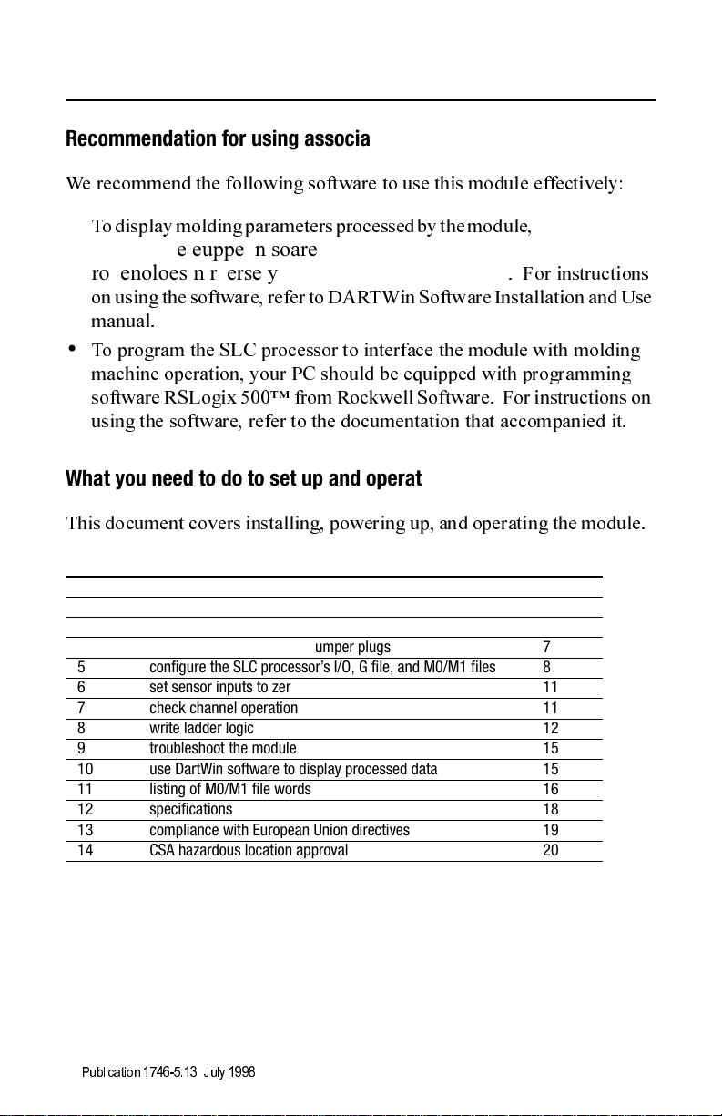
What you need to do to set up and operate the module
This document covers installing, powering up, and operating the module.
Section Description Page
1 what the module does 3
2 wire module I/O 4
3 module I/O 5
4 configure the module with jumper plugs 7
5 configure the SLC processor’s I/O, G file, and M0/M1 files 8
6 set sensor inputs to zero 11
7 check channel operation 11
8 write ladder logic 12
9 troubleshoot the module 15
10 use DartWin software to display processed data 15
11 listing of M0/M1 file words 16
12 specifications 18
13 compliance with European Union directives 19
14 CSA hazardous location approval 20
Publication 1746-5.13 July 1998
Page 3

Mold Pressure Module 3
1. What the module does
The module processes and extracts cyclic injection molding data for
display on your PC, and responds to alarms that you set to monitor
critical molding parameters.
When used with the Pro-Set 200 Injection Molding Control System,
the module helps you:
•
achieve a quicker setup time to obtain optimum part quality
•
maintain that quality over the production run
The module and associated DARTWin software help you to set up the
injection molding machine for optimum performance. Then you set
alarm limits on critical parameters to detect deviations while making
parts. You can also set a critical mold pressure to transfer the injection
process each machine cycle.
The module is designed for use with the SLC 5/03 (or later) processor.
You program it to interface with the injection molding machine. The
module has two independent channels to accept analog pressure inputs
from sensors or from the SLC processor across the backplane. It
returns alarm signals and processed molding parameters to the SLC
processor for your application programming and to your PC for
graphic display. We show the module in a typical Pro-Set 200 system.
Power
Supply
PanelView 550
Operator Interface
SLC 500 Processor System with
I/O and special-purpose modul es
SLC
5/04P
Fast Analog
I/O Modules
I/O for Injector,
Clamp, & Ejectors
Empty
Barrel Temp
Slot
Modules
4-wire sensor
(mold pressure)
Personal Computer with
DARTWin Software
1746-
MPM
P
T
Digital I/O
Modules
P
2-wire sensor
T
(hydraulic pressure)
Publication 1746-5.13 July 1998
Page 4
4 Mold Pressure Module
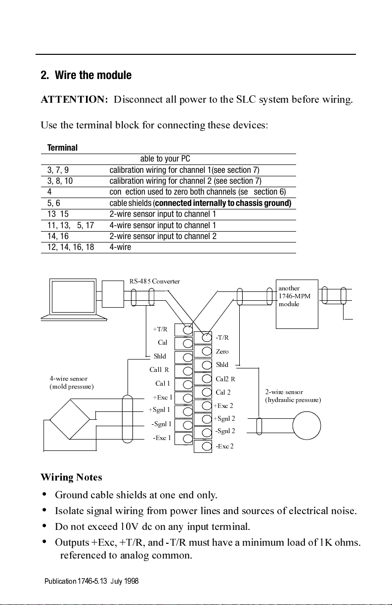
2. Wire the module
ATTENTION:
Disconnect all power to the SLC system before wiring.
Use the terminal block for connecting these devices:
Terminal # Device
1, 2 RS-485 cable to your PC
3, 7, 9 calibration wiring for channel 1(see section 7)
3, 8, 10 calibration wiring for channel 2 (see section 7)
4 connection used to zero both channels (see section 6)
5, 6 cable shield s (connected internally to chassis ground)
13, 15 2-wire sensor input to channel 1
11, 13, 15, 17 4-wire sensor input to channel 1
14, 16 2-wire sensor input to channel 2
12, 14, 16, 18 4-wire sensor input to channel 2
RS-485 Converter
+T/R
1
2
-T/R
4
Zero
Shld
6
8
Cal2 R
10
Cal 2
12
+Exc 2
14
+Sgnl 2
-Sgnl 2
16
18
-Exc 2
2-wire sensor
(hydraulic pressure)
4-wire sensor
(mold pressure)
Cal
Shld
Cal1 R
Cal 1
+Exc 1
+Sgnl 1
-Sgnl 1
-Exc 1
3
5
7
9
11
13
15
17
another
1746-MPM
module
Wiring Notes
•
Ground cable shields at one end only.
•
Isolate signal wiring from power lines and sources of electrical noise.
•
Do not exceed 10V dc on any input terminal.
•
Outputs +Exc, +T/R, and -T/R must have a minimum load of 1K ohms.
referenced to analog common.
Publication 1746-5.13 July 19 98
Page 5

Mold Pressure Module 5
3. Module I/O
Inputs
The module has two independent channels that you configure to process
signals from machine sensors (default) or from the SLC output image table
across the backplane. Types of machine sensors include::
level: range application:
low 2mV/V sensitivity mold pressure
4-20mA general purpose
-100 to +100mV bi-directional
high 0-10V hydraulic pressure
Outputs (Summary Data)
The module processes a frame of summary data for each molding cycle,
and alternately makes available the previous frame for display. It does this
for channels 1 and 2. Your ladder logic can read summary data from the
module’s M0/M1 files. You can observe summary data displayed on a PC
equipped with DARTWin software. The PC must be linked to the module
with DARTNet
network from RJG Te chnolo gi es , Inc.
A list of summary data follows. For a complete list with word addresses,
see the M0/M1 File Listing in section 11.
Summary Data Displayed on Your PC and Read by SLC in M0/M1 Files
injection cycle time
peak injection pressure
minimum cycle pressure
time to peak pressure
trigger time (off to on to off) for T1 (injection forward - fill, pack, and hold)
trigger time (off to on to off) for T2 (fill)
trigger time (off to on to off) for T3 (screw backup)
trigger time (off to on to off) for T4 (mold closed)
integral to peak pressure in units of PSIxSec
integral of trigger 1 (injection forward) in units of PSIxSec
integral of trigger 2 (fill) in units of PSIsec
integral of trigger 3 (screw backup) in units of PSIxSec
integral of trigger 4 (mold closed) in units of PSIxSec
integral of injection cycle in units of PSIxSec
Publication 1746-5.13 July 1998
Page 6
6 Mold Pressure Module
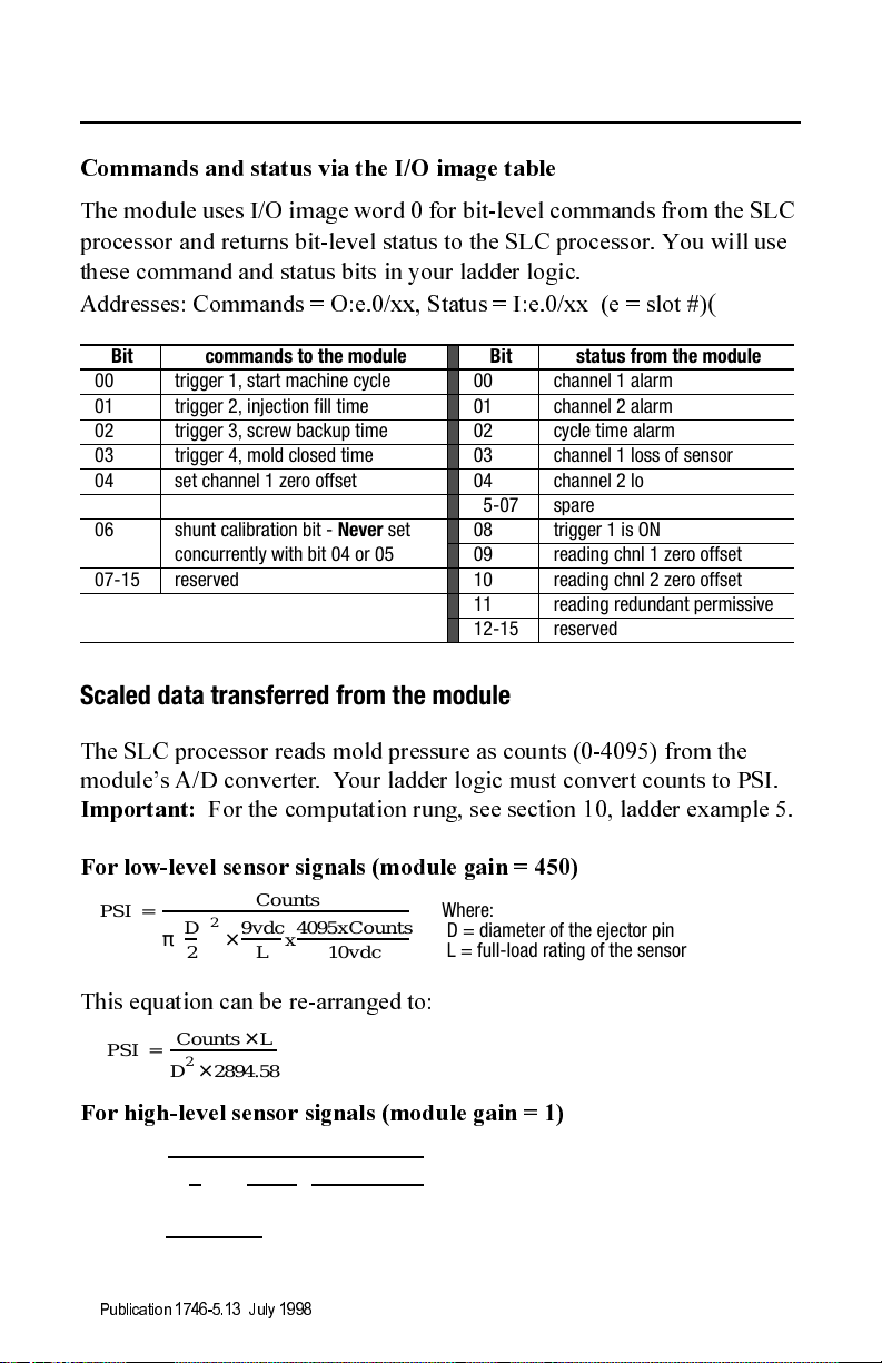
Commands and status via the I/O image table
The module uses I/O image word 0 for bit-level commands from the SLC
processor and returns bit-level status to the SLC processor. You will use
these command and status bits in your ladder logic.
Addresses: Comm ands = O:e.0/xx, Status = I: e.0/ xx (e = slot #)
Bit commands to the module Bit status from the module
00 trigger 1, start machine cycle 00 channel 1 alarm
01 trigger 2, injection fill time 01 channel 2 alarm
02 trigger 3, screw backup time 02 cycle time alarm
03 trigger 4, mold closed time 03 channel 1 loss of sensor
04 set channel 1 zero offset 04 channel 2 loss of sensor
05 set channel 2 zero offset 05-07 spare
06 shunt calibration bit - Never set
concurrently with bit 04 or 05
07-15 reserved 10 reading chnl 2 zero offset
08 trigger 1 is ON
09 reading chnl 1 zero offset
11 reading redundant permissive
12-15 reserved
(
Scaled data transferred from the module
The SLC processor reads mold pressure as counts (0-4095) from the
module’s A/D converter. Your ladder logic must convert counts to PSI.
Important:
For low-level sensor signals (module gain = 450)
PSI
For the computation rung, see section 10, ladder example 5.
2
× x
Counts
9vdc
------------
L
4095xCounts
----------------------------------
10vdc
Where:
D = diameter of the ejector pin
L = full-load rating of the sensor
--------------------------------------------------------------------------
=
D
--- -
π
2
This equation can be re-arranged to:
Counts L×
------------------------------- -
PSI
=
2
2894.58×
D
For high-level sensor signals (module gain = 1)
2
× x
3612.2×
Counts
10vdc
---------------
L
4095xCounts
----------------------------------
10vdc
Important:
For a sensor with 20mA full-load output,
use this same computation.
-----------------------------------------------------------------------------
PSI
=
D
--- -
π
2
Counts L×
-----------------------------
=
PSI
Publication 1746-5.13 July 19 98
2
D
Page 7
Mold Pressure Module 7
Pressure values transferred from the SLC data table to the module must be
integer numbers in units of PSI. If using the Pro-Set 200 Injection Control
System , the ladder logic provides pressur e val ues in the corre ct format.
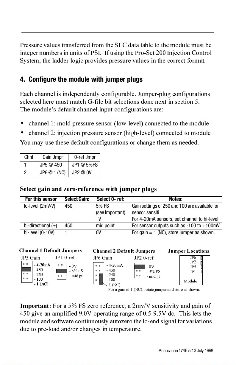
4. Configure the module with jumper plugs
Each channel is independently configurable. Jumper-plug configurations
selected here must match G-file bit selections done next in section 5.
The module’s default channel input configurations are:
•
channel 1: mold pressure sensor (low-level) connected to the module
•
channel 2: injection pressure sensor (high-level) connected to module
You may use these default configurations or change them as needed.
Chnl Gain Jmpr 0-ref Jmpr
1 JP5 @ 450 JP1 @ 5%FS
2 JP6 @ 1 (NC) JP2 @ 0V
Select gain and zero-reference with jumper plugs
For this sensor Select Gain: Select 0- ref: Notes:
lo-level (2mV/V) 450 5% FS
(see Important)
lo-level (4-20mA) 1 0V For 4-20mA sensors, set channel to hi-level.
bi-directional (±) 450 mid point For sensor outputs such as -100 to +100mV
hi-level (0-10V) 1 0V For gain = 1 (NC), store jumper as shown.
Gain settings of 250 and 100 are available for
sensor sensitivities of 6 and 9 mV/V.
Channel 1 Default Jumpers
JP5 Gain JP6 Gain
* *
- 4-20mA
- 4-20mA
- 4-20mA
- 4-20mA
- 4-20mA
- 450
- 450
- 450
- 450
- 450
* *
- 250
- 250
- 250
- 250
- 250
* *
- 100
- 100
- 100
- 100
- 100
- 1 (NC)
- 1 (NC)
- 1 (NC)
- 1 (NC)
- 1 (NC)
Important:
JP1 0-ref
* *
- 0V
- 5% FS
- mid pt
* *
For a 5% FS zero reference, a 2mv/V sensitivity and gain of
Channel 2 Default Jumpers
* *
* *
* *
* *
JP2 0-ref
- 4-20mA
- 450
- 250
- 100
- 1 (NC)
For a gain of 1 (NC), rotate jumper and store as shown.
* *
* *
- 0V
- 5% FS
- mid pt
Jumper Locations
JP6
JP2
JP5
JP1
Module
450 give an amplified 9.0V operating range of 0.5-9.5V dc. This lets the
module and software continuously autozero the lo-end signal for variations
due to pre-load and/or changes in temperature.
Publication 1746-5.13 July 1998
Page 8

8 Mold Pressure Module
Select the calibration resistor with jumper plugs
Select the module’s internal calibration resistor or external resistor located
in the sensor or separately wired to the module’s terminal block.
Channel 1 Jumper
JP3 Cal Res JP4 Cal Res
* *
Internal 200K
default position
* *
Channel 2 Jumper
* *
External
* *
* *
* *
Jumper Locations
Module
JP3 JP4
5. Configure the SLC Processor (including I/O, M0/M1, and G file)
This procedure is based on RSLogix500 programming software, version
2.0 or later. For other software, the procedure may vary.
Configure the SLC processor, I/O, size of M0/M1 files, and G file offline
to match your system lay o ut.
1.
With the File pull-down window, open the ladder file associated wit h
this project, or create a project (ladder file) for it.
2.
If you have not already done so, selec t the Contr ol le r Prope rt ie s icon
and launch it. Then select/enter the type of SLC proce s so r.
3.
Select the I/O Configuration icon and launch it. Then select/enter :
A.
Slot number in the I/O chassis for this module
If using this module in a Pro-Set 200 Injection Control System ,
assign this module to slot 7.
B.
Module ID (12935), entered under “Other” in the I/O Module window.
Important:
When you enter the module ID, the processor automatically
reserves the required number of I/O image table words. The location of
those words in the I/O image table is determined by the module’s slot
location in the I/O chassis. Slot location is a required addressing unit.
For example, I:e.6 locates the 6th word in the block of input image table
words assigned to the module in slot e that you entered in A, above.
C.
If you have not already done so, enter the size of I/O chassis and the type
of power supply.
Publication 1746-5.13 July 19 98
Page 9

Mold Pressure Module 9
4.
Select the Adv Configuration icon and launch it. Then select/enter:
A.
Length of M0/M1 files at 106 words, each (listed in section 11).
B.
Length of G file at 94 words.
5.
Select and launch the Enter G Data icon.
A.
Change the display radix to hex. You get this display:
0 4040000
5 00000
10 00000
: :::::
90 00000
B.
Select word one (as shown) and enter the bit-selected data word that
corresponds to the module’s configuration in your application. You
determine the equivalent hex value of this word in next section
G-file Configuration (Initial Hardware Configuration)
.
The module requires software-configured selections in G file word 1.
Bit Purpose Selection
00-02 reserved n/a
03 Chnl 1 source of data 0 = sensor, 1 = SLC output image table
04 Chnl 2 source of data 0 = sensor, 1 = SLC output image table
05-08 reserved n/a
09 Trigger Operation 0 = triggers, 1 = no triggers
10 channel 1 & 2 alarms turned off by T4 0 = no, 1 = yes
11 Channel 1 & 2 alarms go OFF when T4
(mold closed) trigger does the following:
12 Channel 1 sensor level 0 = high, 1 = low (must match jumpers)
13 Channel 2 sensor level 0 = high, 1 = low (must match jumpers)
14 Alarm operation 0 = alarms, 1 = no alarms
15 module reset 1 = set (required)
You may set bits by entering an equivalent bit-set word in hex
0 = goes ON (at mold close),
1 = goes OFF (at mold open)
%
For example, from tables that follow, a hex value of F200 represents:
Senser level = high for both channels, and alarms = off
(bits 15-12 = 1 1 1 1 = F)
Triggers and T4 = off (bits 11-08 = 0 0 1 0 = 2)
Data source = from sensors for both channels (bits 07-00 = 0)
F200
Publication 1746-5.13 July 1998
Page 10

10 Mold Pressure Module
Select the he x-equivalent value from the following table
Bits 07-00
07-05 04 03 02-00 Chnl 1 Data Source Chnl 2 Data Source Hex
0 0 0 0 sensor sensor xx00
0 1 SLC output image tbl sensor xx08
1 0 sensor SLC output image tbl xx10
1 1 SLC output image tbl SLC output image tbl xx18
Bits 11-08
11 10 09 08 Triggers T4 turns alarms OFF? Alarms OFF when T4 Hex
0 0 0 0 ON NO n/a x0xx
0 0 1 0 OFF NO n/a x2xx
0 1 0 0 ON YES Goes ON at mold close x4xx
0 1 1 0 OFF YES Goes OFF at mold open x6xx
1 0 0 0 ON NO n/a x8xx
1 0 1 0 OFF NO n/a xAxx
1 1 0 0 ON YES Goes ON at mold close xCxx
1 1 1 0 OFF YES Goes OFF at mold open xExx
Bits 15-12
15 14 13 12 Chnl 1 sensor level Chnl 2 sensor level Alarms Hex
1 0 0 0 low low ON 8xxx
1 0 0 1 high low ON 9xxx
1 0 1 0 low high ON Axxx
1 0 1 1 high high ON Bxxx
1 1 0 0 low low OFF Cxxx
1 1 0 1 high low OFF Dxxx
1 1 1 0 low high OFF Exxx
1 1 1 1 high high OFF Fxxx
(
Important:
Before operating the module for the first time, you must
download the G file to the module. Do this by downloading your ladder
file, even if it contains no rungs. The SLC processor must be in Program
mode for a download.
Publication 1746-5.13 July 19 98
Page 11

Mold Pressure Module 11
6. Set sensor inputs to zero
If using a sensor input, zero the channel to cancel any pre-load or offset
voltage in the sensor. For mold pressure, zero the channel every machine
cycle. The method to zero the channel depends on the type of sensor.
For this type of sensor: Zero it: with: With this method:
hydraulic pressure (lo-level),
or injection pressure (hi-level)
mold pressure (lo-level) ladder logic
both types (channels 1, 2) Each method works independently. While “zero” is ON, module
a jumper, manually momentarily short “zero” terminal (4) to
“shield” terminal (5 or 6) after wiring,
once at setup.
each machine cycle, toggle bit 04 (chnl 1)
(channel selectable)
or bit 05 (chnl 2) in output image word 0
(Rising-edge enabled, may remain ON for
the cycle, typically triggered on the mold-
closed bit (trigger 4).)
autozero feature of
DARTWin software
(channel selectable)
enabled on DARTWin’s Mold Setup screen
Software stores first value and subtracts it
from subsequent values any machine cycle.
returns status bit 09 (chnl 1) or 10 (chnl 2) in input image word 0.
7. Check channel operation
With DartWin software on your PC, use the calibration resistor to check
channel operation. The sensor must be connected. (See Cal R in Section 4.)
1.
Apply the calibration resistor.
If
configured:
for internal
cal resistor
for external
cal resistor
with
resistor
in module
(200K)
connect to module terminal block:
a) short “Cal” (terminal 3) to “Shld”
(terminal 5 for channel 1 or 6 for channel 2)
in sensor b) cal resistor between “Cal R” and “Cal”
(between terminals 7 & 9 for channel 1,
or terminals 8 & 10 for channel 2)
separate
from
sensor
c) make two connections:
•resistor between “Cal R” and “+Sgnl”
(between terminals 7 & 13 for channel 1,
or terminals 8 & 14 for channel 2)
• jumper wire between “Cal” and “+Exc”
(between terminals 9 & 11 for channel 1,
or terminals 10 & 12 for channel 2)
Publication 1746-5.13 July 1998
+T/R
Cal
Shld
Cal1 R
Cal 1
+Exc 1
+Sgnl 1
-Sgnl 1
-Exc 1
01
a
b
17
c
Page 12
12 Mold Pressure Module
2.
Observe the di splaye d pressure value.
With DARTWin softwa re running on your PC, obse rve t he displa yed peak
pressure. It should be proportional to the bridge imbalance.
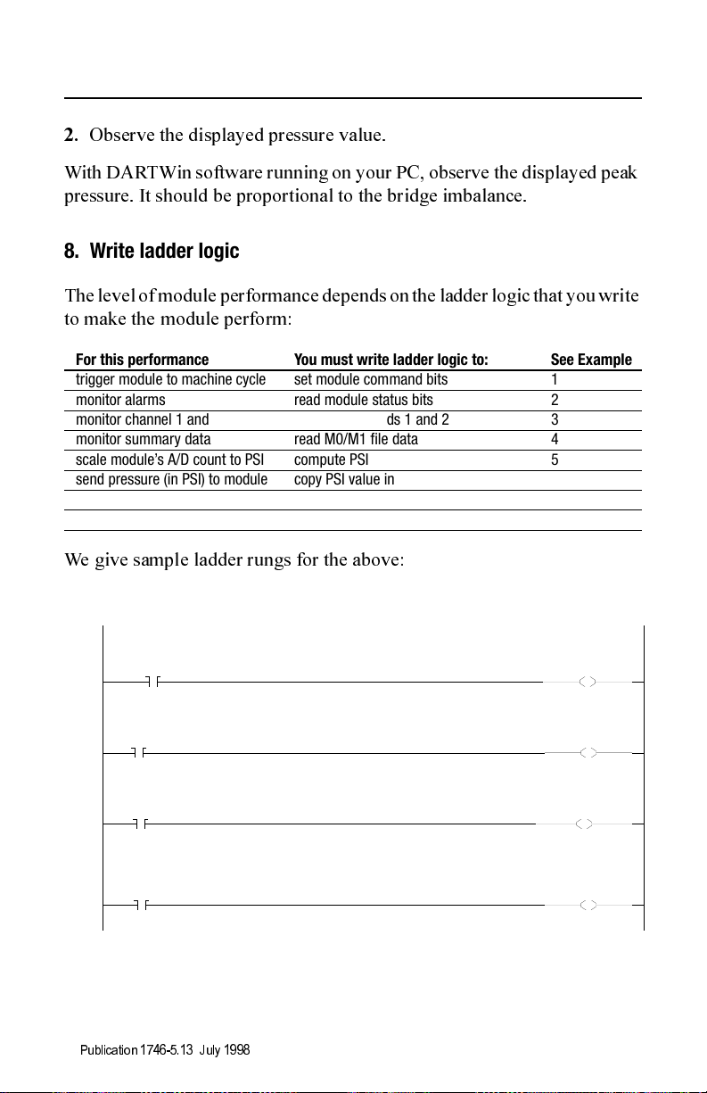
8. Write ladder logic
The level of module performance depends on the ladder logic that you write
to make the module perform:
For this performance You must write ladder logic to: See Example
trigger module to machine cycle set module command bits 1
monitor alarms read module status bits 2
monitor channel 1 and 2 data read status words 1 and 2 3
monitor summary data read M0/M1 file data 4
scale module’s A/D count to PSI compute PSI 5
send pressure (in PSI) to module copy PSI value into output image table 6
save M0/M1 config data copy M0/M1 files into selected N files 7
restore M0/M1 config data copy N files into M0/M1 files 8
We give sample ladder rungs for the above:
Example 1
Injection
Forward
(In For Inject,
Pack and Hold)
0000
0001
0002
0003
B9:16
Injection
Profile
Active
B106:1
15
Initiate
Plasticat ion
B3:4
9
Initiate
Clamp
Close
(Auto)
B3:7
1
4
Publication 1746-5.13 July 19 98
41317
MPM: Trigger 1 is
ON (start machine
cycle)
O:8
0
MPM: Trigger 2 is
ON (inject fill)
O:8
1
MPM: Trigger 3 is
ON (plasticate time)
O:8
2
MPM: Trigger 4 is
ON (cure time)
O:8
3
Page 13

Example 2
Mold Pressure Module 13
0000
Example 3
Read Channel 1 Sample Data
0000
Read Channel 1 Sample Data
0001
Channel 1 Alarm
I:8
0
OTHER
Channel 2 Alarm
I:8
1
OTHER
Cycle Time Alarm
I:8
2
OTHER
Ch. 1 Sensor Loss
I:8
3
OTHER
Ch. 2 Sensor Loss
I:8
4
OTHER
Jump to Alarm
Handler
JSR
JSR
Jump To Subroutine
SBR File Number U:100
41318
Move
Source I:8.1
0<
Dest N7:0
0<
Move
Source I:8.2
0<
Dest N7:1
0<
41319
MOV
MOV
MOV
MOV
Example 4
Read Frame 1 Status
0000
If Frame 1 summary data is new, copy to integer file
0001
0002
0003
N7:0
8
Read Frame 2 Status
If Frame 2 summary data is new, copy to integer file
N7:0
8
COP
COP
Copy File
Source #M0:8.49
Dest #N7:0
Length 1
COP
COP
Copy File
Source #M0:8.54
Dest #N7:1
Length 28
COP
COP
Copy File
Source #M0:8.76
Dest #N7:0
Length 1
COP
COP
Copy File
Source #M0:8.81
Dest #N7:1
41320
Length 28
Publication 1746-5.13 July 1998
Page 14
14 Mold Pressure Module
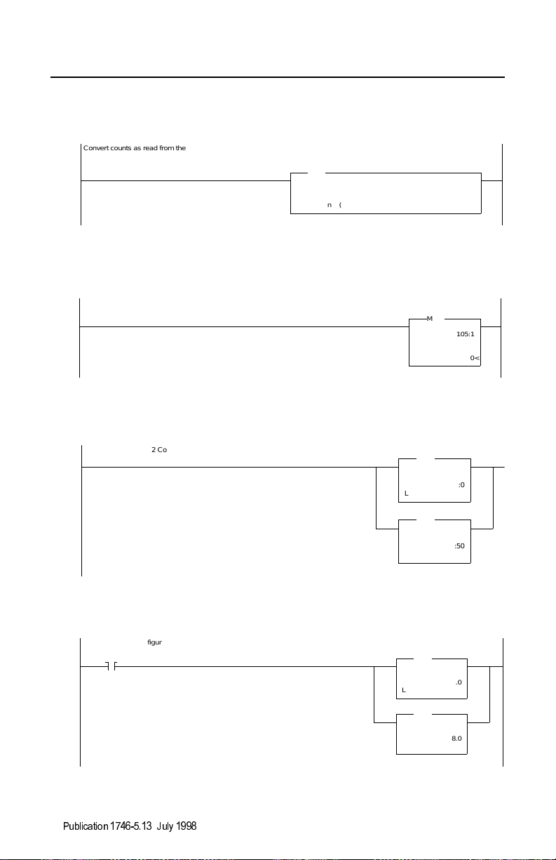
E
5
xample
Convert counts as read from the module to PSI, where
F8:0 = Full load sensor range, in pounds
F8:1 = Ejector pin diameter, in inches
0000
CPT
CPT
Compute
Dest F8:2
0.0<
Expression ( I:8.1 * F8:0 ) | ( ( F8:1 * F8:1 ) * 2894.58 )
41321
Example 6
0000
Example 7
Save Channel 1 and 2 Configuration
0000
Example 8
Restore module configuration on first program scan
First Pass
0000
S2:1
15
41322
41323
Write Hydraulic
Pressure to MPM
MOV
MOV
Move
Source N105:1
0<
Dest O:8.2
0<
COP
COP
Copy File
Source #M0:8.0
Dest #N7:0
Length 49
COP
COP
Copy File
Source #M1:8.0
Dest #N7:50
Length 49
COP
COP
Copy File
Source #N7:1
Dest #M0:8.0
Length 49
COP
COP
Copy File
Source #N7:50
Dest #M1:8.0
Length 49
41324
Publication 1746-5.13 July 19 98
Page 15

Mold Pressure Module 15
9. Troubleshooting with LEDs
LEDs indicate operating conditions detected by the module:
INPUT
FAULT
TRIGGER 1
TxDATA
RxDATA
Status: Indicates:
loss of a sensor signal, or
on
on running a machine cycle
flicker transmitting on DartNet
flicker receiving on DartNet
lo-level sensor is out of range
10. Use DARTWin software to display processed data
Refer to the DARTwin Software Instruction and Use Manual.
This concludes the procedures to set up and operate the 1746-MPM module.
In the next section, we present the M0/M1 file listing .
Publication 1746-5.13 July 1998
Page 16

16 Mold Pressure Module
11. Listing of M0/M1 file words
You load M0/M1 file data into the module from your PC equipped with
DARTwin software. M0 and M1 files contain:
•
module configuration data, loaded by DARTWin software (words 0-48)
•
summary data processed by the module (words 49-106)
Summary data (in units of A/D counts x 1/100 sec.) is stored in t wo frames:
frame 1 = words 49-75
frame 2 = words 76-106
Important:
Address (e = module slot number) Description
Module Config Data
Channel 1 (M0) Channel 2 (M1)
M0:e.0, 2, 4, 6 M1:e.0, 2, 4, 6 Dead time, trigger ON (for triggers 1, 2, 3, 4)
M0:e.1, 3, 5, 7 M1:e.1, 3, 5, 7 Dead time, trigger OFF (for triggers 1, 2, 3, 4)
M0:e.8 M1:e.8 Alarm control word (enable/disable)
M0:e.9 M1:e.9 Alarm level, cycle time low
M0:e.10 M1:e.10 Alarm level, cycle time high
M0:e.11 M1:e.11 Alarm level, peak high
M0:e.12 M1:e.12 Alarm level, peak low
M0:e.13 M1:e.13 Alarm level, peak time high
M0:e.14 M1:e.14 Alarm level, peak time low
M0:e.15, 17, 19, 21 M1:e.15, 17, 19, 21 Alarm level, trigger time low (triggers 1, 2, 3, 4)
M0:e.16, 18, 20, 22 M1:e.16, 18, 20, 22 Alarm level, trigger time high (triggers 1, 2, 3, 4)
M0:e.23 M1:e.23 Alarm level, minimum in frame, low
M0:e.24 M1:e.24 Alarm level, minimum in frame, high
M0:e.25, 26 M1:e.25, 26 Alarm level, peak integral low
M0:e.27, 28 M1:e.27, 28 Alarm level, peak integral high
M0:e.29, 30 M1:e.29, 30 Alarm level, trigger 1 integral low
M0:e.31, 32 M1:e.31, 32 Alarm level, trigger 1 integral high
M0:e.33, 34 M1:e.33, 34 Alarm level, trigger 2 integral low
M0:e.35, 36 M1:e.35, 36 Alarm level, trigger 2 integral high
M0:e.37, 38 M1:e.37, 38 Alarm level, trigger 3 integral low
M0:e.39, 40 M1:e.39, 40 Alarm level, trigger 3 integral high
M0:e.41, 42 M1:e.41, 42 Alarm level, trigger 4 integral low
M0:e.43, 44 M1:e.43, 44 Alarm level, trigger 4 integral high
M0:e.45, 46 M1:e.45, 46 Alarm level, frame integral low
M0:e.47, 48 M1:e.47, 48 Alarm level, frame integral high
See summary data notes on page 18.
Publication 1746-5.13 July 19 98
Page 17

Mold Pressure Module 17
Frame 1 summary data
M0:e.49 M1:e.49 Read bit 8 for new frame data
M0:e.50 M1:e.50 Pointer to frame data
M0:e.51 M1:e.51 Number of summary-data samples (incl 1st & last)
M0:e.52, 53 M1:e.52, 53 Start time of frame (30 bits)
M0:e.54, 55 M1:e.54, 55 Integral to peak (30 bits)
M0:e.56, 57 M1:e.56, 57 Integral over trigger 1 (30 bits)
M0:e.58, 59 M1:e.58, 59 Integral over trigger 2 (30 bits)
M0:e.60, 61 M1:e.60, 61 Integral over trigger 3 (30 bits)
M0:e.62, 63 M1:e.62, 63 Integral over trigger 4 (30 bits)
M0:e.64, 65 M1:e.64, 65 Integral over frame (30 bits)
M0:e.66, 67 M1:e.66, 67 Alarm bits (30 bits)
M0:e.68 M1:e.68 Frame length in 1/100 second (15 bits)
M0:e.69 M1:e.69 Peak in frame (15 bits)
M0:e.70 M1:e.70 Time to peak in frame (in 1/100 second)15 bits)
M0:e.71 M1:e.71 Trigger 1 ON time
M0:e.72 M1:e.72 Trigger 2 ON time
M0:e.73 M1:e.73 Trigger 3 ON time
M0:e.74 M1:e.74 Trigger 4 ON time
M0:e.75 M1:e.75 Min value in fram e (12 bits) or first sample (autozero)
Frame 2 summary data
M0:e.76 M1:e.76 Read bit 8 for new frame data
M0:e.77 M1:e.77 Pointer to frame data
M0:e.78 M1:e.78 Number of summary-data samples (incl 1st & last)
M0:e.79, 80 M1:e.79, 80 Start time of frame (30 bits)
M0:e.81, 82 M1:e.81, 82 Integral to peak (30 bits)
M0:e.83, 84 M1:e.83, 84 Integral over trigger 1 (30 bits)
M0:e.85, 86 M1:e.85, 86 Integral over trigger 2 (30 bits)
M0:e.87, 88 M1:e.87, 88 Integral over trigger 3 (30 bits)
M0:e.89, 90 M1:e.89, 90 Integral over trigger 4 (30 bits)
M0:e.91, 92 M1:e.91, 92 Integral over frame (30 bits)
M0:e.93, 94 M1:e.93, 94 Alarm bits (30 bits)
M0:e.95 M1:e.95 Frame length in 1/100 second (15 bits)
M0:e.96 M1:e.96 Peak in frame (15 bits)
M0:e.97 M1:e.97 Time to peak in frame (in 1/100 second)15 bits)
M0:e.98 M1:e.98 Trigger 1 ON time
M0:e.99 M1:e.99 Trigger 2 ON time
M0:e.100 M1:e.100 Trigger 3 ON time
M0:e.101 M1:e.101 Trigger 4 ON time
M0:e.102 M1:e.102 Min value in frame (12 bits ) or first sample (autozero)
M0:e.103 M1:e.103 Alarm limit time in 1/100 second
M0:e.104 M1:e.104 Alarm limit counts in 1/100 second
M0:e.105 M1:e.105 Cycle counter
M0:e.106 M1:e.106 Rejects counter
Publication 1746-5.13 July 1998
Page 18
18 Mold Pressure Module
Summary data notes
Single-word
summary values are stored with bytes reversed. You must use
the Swap instruction to convert them to integ er format.
Double-word
summary values are stored as integer pairs, with the low-
word value stored in the lower address of the pair, high-word value in upper.
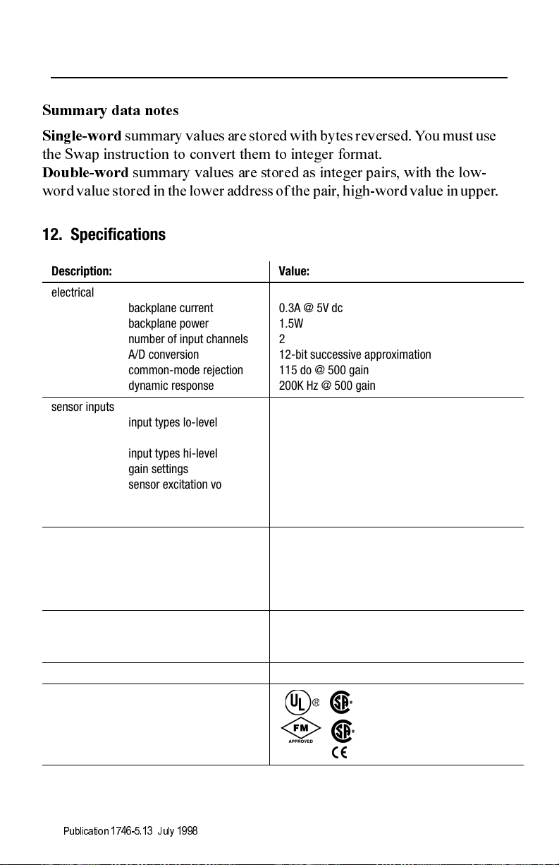
12. Specifications
Description: Value:
electrical
backplane current
backplane power
number of input channels
A/D conversion
common-mode rejection
dynamic response
sensor inputs
input types lo-level
input types hi-level
gain settings
sensor excitation voltage
sensor excitation current
isolation from backplane
mechanical
module ID
number of LED indicators
cable for channels
cable for DartNets
temperature
operating
storage
relative humidity 5% to 95% noncondensing
agency certification
(when product or packaging is marked)
1
0.3A @ 5V dc
1.5W
2
12-bit successive approximation
115 do @ 500 gain
200K Hz @ 500 gain
2, 6, and 9 mV/V strain gage
4-20mA self-powered
0-10V dc
1, 100, 250, 450
10.000V dc ±0.002V dc
35mA per channel
1500V rms
12935
4 (alarm condition and module status)
Belden 8102
Belden 9462
0° to 60° C (32 to 140° F)
-40° to 85° C (-40 to 185° F)
Class I Division 2 Hazardous
marked for all applicable directives
1. CSA certification - Class I Division 2, Group A, B, C, D or nonhazardous locations
FM approved - Class I, Division 2, Group A, B, C, D or nonhazardous locations
Publication 1746-5.13 July 19 98
Page 19

Mold Pressure Module 19
13. Compliance with European Union Directive
If this product has the CE mark it is approved for installation within the
European Community or EEA regions. It has been designed and tested to
meet the following directives.
EMC Directive
This product is tested to meet Council Directive 89/336/EC
Electromagnetic Compatibility (EMC) and the following standards, in
whole or in part, documented in a technical construction file:
• EN 50081-2
EMC - Generic Emission Standard, Part 2 - Industrial Environment
• EN 50082-2
EMC - Generic Immunity Standard, Part 2 - Industrial Environment
This product is intended for use in an industrial environment.
Low Voltage Directive
This product is tested to meet Council Directive73/23/EEC Low Voltage,
by applying the safety requirements of EN 61131-2 Programmable
Controllers, Part 2 - Equipment Requirements and Tests. For specific
information required by EN 61131-2, see the appropriate sections in this
publication, as well as the Industrial Automation Wiring and Grounding
Guidelines for Noise Immunity, publication 1770-4.1.
This equipment is classified as open equipment and must be mounted in
an enclosure during operation to provide safety protection
.
Publication 1746-5.13 July 1998
Page 20

20 Mold Pressure Module
14. CSA Hazardous Location Approval
CSA certifies products for general use as well as for use in hazardous
locations.
below, and not by statements in any user documentation.
CSA certification is indicated by the product label
as shown
Example of the CSA certification product label:
To comply with CSA certification for use in
CL I, DIV 2
GP A,B,C,D
TEMP
hazardous locations, the following information
becomes a part of the product literature for this
CSA-certified industrial control product.
•
This equipment is suitable for use in Class I, Division 2, Groups A, B,
C, D, or non-hazardous locations only.
•
The products having the appropriate CSA markings (that is, Class I,
Division 2, Groups A, B, C, D) are certified for use in other equipment
where the suitability of combination (that is, application or use) is
determined by the CSA or the loca l inspection o ffice having jurisdiction.
Important:
Due to the modular nature of a pr ogr am mabl e control system,
the product with the highest temperature rating determines the
overall temperature code rating of a programmable control
system in a Class I, Divisi on 2, location. The temperature code
rating is marked on the product label as shown.
Temperature code rating
:
CL I, DIV 2
GP A,B,C,D
TEMP
Look for temperature
code rating here.
Publication 1746-5.13 July 19 98
Page 21

Mold Pressure Module 21
The following warnings apply to products having CSA certification for use
in hazardous locations.
ATTENTION:
!
CSA logo is a registered trademark of the Canadian Standards Association.
• Substitution of components may impair suitability for
Class I, Divisio n 2
• Do not replace components unless power has been
switched off or the area is known to be non-hazardous.
• Do not disconnect equipment unle ss power has been
switched off or the area is known to be non-hazardous.
• Do not disconnect connectors unless power has been
switched off or the area is known to be non-hazardous.
Secure any user-supplied connectors that mate to external
circuits on this equipm e nt by using screws, sliding latches,
threaded connectors, or other means such that any
connection can wit hst and a 15 Newton (3.4 lb.) separa t i ng
force applied for a minimum of one minute.
• Batteries must only be changed in an area known to be non-
hazardous.
Explosion hazard:
Publication 1746-5.13 July 1998
Page 22

22 Mold Pressure Module
Approbation d’utilisation dans des emplacements dangereux par CSA
La CSA certifie les produits d'utilisation generale aussi bien que ceux qui
s'utilisent dans des emplacements dangereux. La certification CSA en
vigueur est indiquee par l'etiquette du produit et non par des affirmations
dans la documentation a l'usage des utilisateurs.
Exemple d'etiquette de certification d'un produit par
la CSA:
CL I, DIV 2
GP A,B,C,D
TEMP
Pour satisfaire a la certification de la CSA dans des
endroits dangereux, les informations suivantes font
partie integrante de la documentation ce produit
industriel de controle certifie par la CSA.
•
Cet equipement convient a l'utilisation dans des emplacements de Classe
1, Division 2, Groupes A, B, C, D, ou ne convient qu'a l'utilisation dans
des endroits non dangereux.
•
Les produits portant le marquage approprie de la CSA (c'est a dire,
Classe 1, Division 2, Groupes A, B, C, D) sont certifies a l'utilisation
pour d'autres equipements ou la convenance de combinaison
(application ou utilisation) est determinee par la CSA ou le bureau local
d'inspection qualifie.
Important:
Par suite de la nature modulaire du systeme de controle
programmable, le produit ayant le taux le plus eleve de
temperature determine le taux d'ensemble du code de
temperature du systeme de controle d'un programmable dans
un emplacement de Classe 1, Division 2. Le taux du code de
temperature est indique sur l'etiquette du produit.
Taux du code de temperature:
Publication 1746-5.13 July 19 98
CL I, DIV 2
GP A,B,C,D
TEMP
Look for temperature
code rating here.
Page 23

Mold Pressure Module 23
Les avertissements suivants s'appliquent aux produits ayant la certification
CSA pour leur utilisation dans des emplacements dangereux.
ATTENTION:
!
Le sigle CSA est la marque deposee de l'Association des Standards pour le Canada.
• La substitution de composants peut rendre ce materiel
inacceptable pour lesemplac em ents de Classe I, Div. 2.
• Couper le courant ou s'assurer quel'em plac eme nt est
designe non danger e ux avant de rempla cer lescomposants.
• Avant de debrancher l'equipement, couper le courant ou
s'assurer que l'emplacement est designe non dangereux.
• Avant de debranche r les connecte urs, couper le courant ou
s'assurer que l'emplacement est reconnu non dangereux.
Attacher tous co nnec teurs fournis par l'utilisate ur et re li es
aux cir cui ts externes de cet appareil a l 'aide de vis, loquets
coulissants, connect eurs fil etes ou autres moy ens
permettant aux connexions de resister a une force de
separation de 15 newtons (3,4 lb. - 1,5 kg) appliquee
pendant au moins une minute.
• Afin d'eviter tout risque d'explosio n, s'ass ure r que
l'emplacement est designe non dangereux avant de changer
la batterie.
Risque d'explosion:
Publication 1746-5.13 July 1998
Page 24

Mold Pressure Module 24
SLC500™ is a trademark of Rockwell Automation
DARTW in™ is a trademark of RJG Technologies
Publication 1746-5.13 July 1998 PN 955132-89
Copyright 1998 Rockwell International Corp. Printed in USA.
 Loading...