

Page 1

Quick Start
Thermocouple/mV Isolated Input Module
Cat. No. 1746-INT4
Contents
Use this document as a guide to install and wire the 1746-INT4 m odule. If you need
more detailed information, refer to the Thermocouple/mV Isolated Input Module
User Manual, publication 1746-6.16.
For this info rmation See page
Important User Information 2
Prevent Electrostatic Discharge 3
How to Get the Related User Manual 4
Unpack the Module 4
Review Power Requirements 4
Install the Module and Connect the Thermocouples 5
Configure the Software 12
Set Up Channel 0 13
Program the Transfer of the Configuration Word 14
Write Ladder Logic to Process Input Data 15
Apply Power and Download Your Program 15
Troublshoot the Module 16
Channel Configuration Worksheet 19
For this reference information See page
Specifications 18
Publication 1746-QS002 B-EN-P - July 2002
Page 2

2 Thermocouple/mV Isolated Input Module
WARNING
!
ATTENTION
!
IMPORTANT
Important User Information
Because of the variety of uses for the products described in this publication, those
responsible for the application and use of these products must satisfy themselves that all
necessary steps have been taken to assure that each application and use meets all
performance and safety requirements, including any applicable laws, regulations, codes
and standards.
In no event will R ockwell Automation be responsible or lia ble for indirect or
consequential damage resulting from the use or application of these products.
Any illustratio ns, charts, samp le programs, a nd la yout example s shown in this
publication are intended solely for purposes of example. Since there are many variables
and requirements associated with any particular installation, Rockwell Automation does
not assume responsibility or liability (to include intellectual property liability) for actual
use based upon the examples shown in this publication.
TM
Allen-Bradley
and Maintenance of Solid-State Control (available from your loca l Ro ckwel l Aut omati on
office), describes some important differences between solid-state equipment and
electromechanical devices that should be taken into consideration when applying
products such as those described in thi s pu blication.
Reproduction of the contents of this copyrighted publication, in whole or part, without
written permission of Rockwell Automation, is prohibited.
Throughout this publication, notes may be used to make you aware of safety
considerations. The following annotations and their accompanying statements help you
to identify a potential hazard, avoid a potential hazard, and recognize the consequences
of a potential hazard:
publication SGI-1.1, Safety Guidelines for the Application, Installation
IMPORTANT
Publication 1746-QS002B-EN-P - July 2002
Identifies information about practices or circumstances that can
cause an explosion in a hazardous environment, which may
lead to personal injury or death, property damage, or
economic loss.
Identifies information about practices or circumstances that can
lead to personal injury or death, property damage, or
economic loss.
Identifies information that is critical for successful application
and understanding of the product.
Page 3

Thermocouple/mV Isolated Input Module 3
ATTENTION
!
ATTENTION
!
Environment and Enclosure
This equipm ent is intended for use in a Pollution Degree 2
industrial environment, in overvoltage Category II applications (as
defined in IEC p ublica tion 6 0664- 1), at altit udes u p to 2000 me ters
without derating.
This equipmen t i s co nsidered Group 1, Cl a ss A in dustrial
equipment according to IEC/CISPR Publication 11. Without
appropriate precautions, there may be potential difficulties
ensuring electromagnetic compatibility in other environments due
to conducted as well as radiated disturbance.
This equipment is supplied as "open type" equipment. It must be
mounted within an enclosure that is suitably designed for those
specific environmental conditions that will be present and
appropriately designed to prevent personal injury resulting from
accessibility to live parts. The interior of the enclosure must be
accessible only by the use of a tool . S ubsequent sect i ons of this
publication may contain additional information regarding specific
enclosure type rat ings that are required to comply with certain
product safety certifications.
See NEMA Standards p ublication 250 and IEC publication 60529,
as applicable, for explanations of the degrees of protection
provided by different types of enclosure. Also, see the appropriate
sections in this publication, as well as the Allen-Bradley
publication 1770-4.1 ("Industrial Au t oma t ion Wiring and
Grounding Guidelines"), for additional installation requirements
pertaining to this equipment.
Prevent Electrostatic Discharge
This equipment is sensitive to electrostatic discharge which can
cause internal damage and affect normal operation. Follow these
guidelines wh en you handle this equipment :
• touch a grounded object to discharge potential static
• wear an approved grounding wrist strap
• do not touch connectors or pins on component boards
• do not touch circuit components inside the equipment
• if available, use a static-safe workstation
• when not in use, store the equipment in appropriate
static-safe packaging
Publication 1746-QS002 B-EN-P - July 2002
Page 4

4 Thermocouple/mV Isolated Input Module
TIP
How to Get the Related User Manual
The following table describes the related user manual that is available for this
module. To order a copy or to view or download an online version, visit The
Automation Bookstore at: www.theautomationbookstore.com
For more detailed informa tion about: See this document: Publication number:
Installation, configuration, programming,
diagnostics and troubleshooting
Thermocouple.mV Isolated Input
Module User Manual
1746-6.16
Unpack the Module
Unpack the module making sure that the contents include:
• module (catalog number 1746-INT4)
• factory-installed removable terminal block with CJC sensors attached
(catalog number 1746-RT32)
• this Quick Start document (publication number 1746-QS002B-EN-P)
If the contents are incomplete, contact your local Rockwell Automation
representative for assistance.
Review Power Requi rements
Review the power requirements of the modules drawing power from the chassis
power supply.
1. The fixed 2-slot chassis supports 2 1746-INT4 modules. If combining an
INT4 module with a different type of module, refer to Considerations for a
Fixed Controller in Chapter 3 of the user manual.
2. For a modular system, compute the total load on the system power supply
using the procedure described in the SLC Installation and Operation Manual
for Modular Controllers (publication number 1747-UM011) or the SLC 500
Family System Overview (publication 1747-SO001).
For more detailed information on these procedures, refer to
Chapter 3 (Installation and Wiring) and Appendix A
(Module Specifications) of the user manual, publication
1746-6.16.
Publication 1746-QS002B-EN-P - July 2002
Page 5
Thermocouple/mV Isolated Input Module 5
WARNING
!
WARNING
!
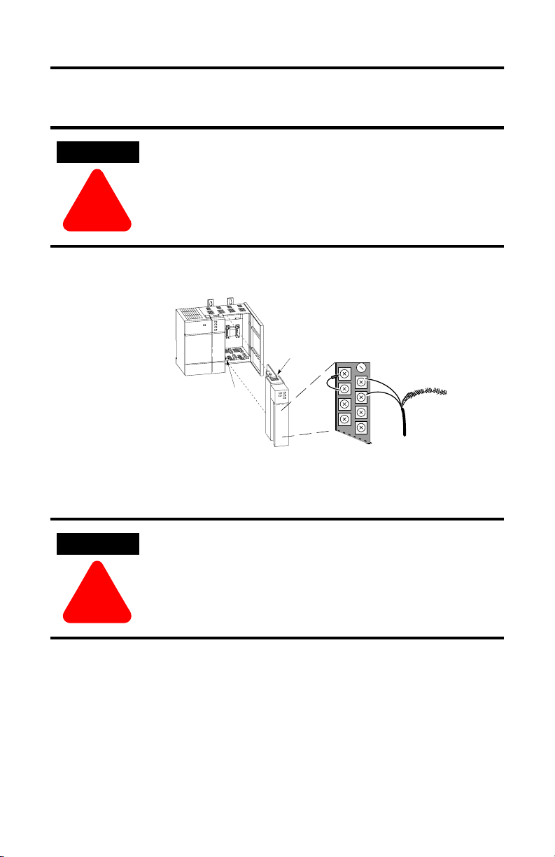
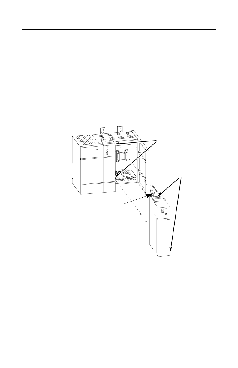
Install the Module and Connect the Thermocouples
If you insert or remove the module while backplane power is
on, an electrical arc can occur. This could cause an explosion
in hazardous location installations. Be sure that power is
removed or the area is nonhazardous before proceeding.
Insert/remove the module into/from the I/O chassis
(slot 1 in this example procedure).
Important:
Thermocouple inputs are highly
susceptible to electrical noise.
To minimize interference:
Place processor and I/O chassis
in an industrial enclosure.
± Keep signal wires as far from
power and load lines as possible.
Use shielded, twisted-pair
thermocouple extension wire.
Ground each shield only at one end.
Use correct thermocouple polarity.
Keep all unshielded leads short.
Connect the terminal block GND
(#18) to nearest I/O chassis mtg.
bolt with 12 gauge stranded wire.
card
guide
module release,
top and bottom
Connect thermocouple wires to channels 0-3.
We show an example for channel 0. Make sure
both cold junction compensation (CJC) devices
are securely attached with correct polarity.
Important:
Ground all thermocouple shields
to earth ground at I/O chassis
with 3/8º braid wire. See User
CHL 0+
Manual, figure 3.2.
CHL
0±
CHL 1+
1±
CHL
Thermocouple Wire
CJC
Device
Terminal Block
+
±
A
To install your module into the chassis:
1. Turn off the chassis power supply.
If you insert or remove the module while backplane power is
on, an electrical arc can occur. This could cause an explosion
in hazardous location installations. Be sure that power is
removed or the area is nonhazardous before proceeding.
Publication 1746-QS002 B-EN-P - July 2002
Page 6
6 Thermocouple/mV Isolated Input Module
2. Align the circuit board of the thermocouple module with the card guides
located at the top and bottom of the chassis.
3. Slide the module into the chassis until both top and bottom retaining clips
are secured. Apply firm even pressure on the module to attach it to its
backplane connector. Never force the module into the slot.
4. Cover unused slots with the card slot filler, catalog number 1746–N2.
5. To remove, press the releases at the top and bottom of the module, and slide
the module out of the chassis slot.
card guides
top and bottom
releases
retaining clips
Publication 1746-QS002B-EN-P - July 2002
Page 7

Thermocouple/mV Isolated Input Module 7
WARNING
!
Remove/Install the Removable Term inal Block
The module ships with an attached an 18-p osition removable termi nal block (RTB).
When you install the module, it is not necessary to remove the RTB. If you ever
need to remove it, follow this procedure:
1. Alternately loosen the two retaining screws to avoid cracking the RTB.
CJC sensors
RTB
2. Grasp the RTB at the top and bottom and pull outward and down. When
removing the RTB, be careful not to damage the CJC sensors.
3. Use the write–on label to identify the slot, chassis and module type.
SLOT
MODULE
To install the RTB:
1. Remove power from the SLC 500 chassis.
When you connect or disconnect the Removable Terminal
Block (RTB) with field side power applied, an electrical arc
can occur. This could cause an explosion in hazardous
location installations. Be sure that power is removed or the
area is nonhazardous before proceeding.
RACK
retaining screws
Publication 1746-QS002 B-EN-P - July 2002
Page 8

8 Thermocouple/mV Isolated Input Module
ATTENTION
!
2. Make certain the color of the RTB mathces the color band on the module.
Inserting a wired RTB on an incorrect module can damage the
module’s circuitry when power is restored.
3. View the write–on label to identify the slot, chassis and module type.
SLOT
MODULE
4. Align the RTB retaining screws with the mating connector on the module. Be
careful not to damage the CJC sensors.
CJC sensors
5. Press the RTB firmly onto the connector contacts.
6. Alternately tighten the two retaining screws to avoid cracking the RTB.
Tighten to a maximum 6-8 inch-pounds.
RACK
retaining screws
RTB
Publication 1746-QS002B-EN-P - July 2002
Page 9

Thermocouple/mV Isolated Input Module 9
ATTENTION
!
Wire the RTB
Use the following illustration to wire the RTB:
CJC A+
CJC Assembly
CJC Assembly
Retaining Screw
CJC A-
Do NOT use these
connections
CJC B+
CJC B-
Cold Junction Compensation (CJC)
Do not remove or loosen the cold junction compensating
thermistors located on the terminal block. Both thermistors
are critical to ensure accurate thermocouple input
readings at each channel. The module will not operate in the
thermocouple mode if a thermistor is removed
Retaining Screw
Channel 0+
Channel 0Channel 1+
Channel 1-
Channel 2+
Channel 2Channel 3+
Channel 3-
spare part catalog number:
n/c
1746-RT32
In case of accidental removal of one or both thermistors (part number
A40845-221-01), replace them by connecting them across the CJC terminals located
at the top and/or bottom left side of the terminal block. Always con nect the red lug
to the (+) terminal (to CJC A+ or CJC B+) as shown below.
Always attach red
lug to the CJC+
terminal
CJC Sensor part number
A40845-221-01
Publication 1746-QS002 B-EN-P - July 2002
Page 10

10 Thermocouple/mV Isolated Input Module
Wiring Guidelines
Follow these guidelines when planning your system wiring.
• To limit the pickup of electrical noise, keep thermocouple and millivolt
signal wires away from power and load lines.
• For high immunity to electrical noise, use Alpha 5121 (shielded, twisted pai r)
or equivalent wire for millivolt sensors; or use shielded, twisted pair
thermocouple extension lead wire specified by the thermocouple
manufacturer. Using the incorrect type of thermocouple extension wire or
not following the correct polarity may cause invalid readings. See IEEE Std.
518, Section 6.4.2.7 or contact your sensor manufacturer for additional
details.
• When trimming cable leads, minimize the length of unshielded wires.
• Ground the shield drain wire at only one end of the cable. The preferred
location is at the I/O chassis ground.
• For maximum noise reduction, use 3/8 inch braid wire to connect cable
shields to the nearest I/O chassis mounting bolt. Then connect the I/O
chassis to earth ground. These connections are a requirement regardless of
cable type.
• Tighten terminal screws to 6-8 inch-pounds. Excessive tightening can strip
the screw.
• The open–circuit detector generates approximately 20 nano–amperes into
the thermocouple cable. A total lead resistance of 25 ohms (12.5 one–way)
will produce 0.5 mV of error.
• Follow system grounding and wiring guidelines found in your SLC 500
Modular Hardware Style User Manual, publication 1747–UM011.
Publication 1746-QS002B-EN-P - July 2002
Page 11

Thermocouple/mV Isola ted Input Module 11
Preparing and Wiring the Cables
To prepare and connect cable leads and drain wires, follow these steps:
Remove the foil shield
and drain wire from
sensor-end of the cable
Signal Wires
Extract th e drain wire bu t
remove the foil shield, at
the module-end of the
cable.
1. At each end of the cable, strip some casing to expose individual wires.
2. Trim signal wires to 5–inch lengths beyond the cable casing. Strip about 3/16
inch (4.76 mm) of insulation to expose the ends of the wires.
3. At the module–end of the cables:
- extract the drain wire and signal wires
- remove the foil shield
- bundle the input cables with a cable strap
4. Connect drain wires together and solder them to a 3/8” wire braid, 12” long.
Keep drain wires as short as possible.
5. Connect the 3/8” wire braid to the nearest chassis mounting bolt.
6. Connect the signal wires of each channel to the terminal block.
Drain Wire
Signal Wires
Publication 1746-QS002 B-EN-P - July 2002
Page 12

12 Thermocouple/mV Isolated Input Module
IMPORTANT
7. At the source-end of cables from mV devices (see following figure):
• remove the drain wire and foil shield
• apply shrink wrap as an option
• connect to mV devices keeping the leads short
Make unshielded wires as short as possible.
Wires
3/8
Make unshielded wires as
short as possible.
IMPORTANT
Solder drain wires to
braid at casing.
Connect I/O chassis
bolt to earth ground
Limit braid length to 12” or
less. Solder braid to lug on
bottom row of I/O chassis
If noise persists, try grounding the opposite end of the cable.
Ground one end only.
3/8
Signal
Wires
Chnl 0
Chnl 1
Cables
Chnl 2
Chnl 3
n/c
Terminal Block
Configure the Software
With your programming software already loaded and your computer set for off-line
programming:
1. Identify the type of SLC processor and operating sytstem on the PROG
DIRECTORY FOR PROCESSORS screen.
Publication 1746-QS002B-EN-P - July 2002
2. With the SLC system installed and wired, us the READ CONFIG feature and
follow the prompts to configure the I/O.
3. Enter the rack configuration.
4. Select the type of module in each slot. If 1746-INT4 is not listed, enter ID
code 3515 for OTHER at the bottom of the list.
5. Exit and save to file.
Page 13

Thermocouple/mV Isola ted Input Module 13
TIP
TIP
No manual entry of special I/O configuration (SPIO CONFIG) information is
required. Module ID code automatically assigns the number of input and output
words required by the module. Refer to your configuration software documentation
for more information..
For more detailed information on these procedures, refer to
Chapter 5 (Accessing File s to Configur e I / O)of the user
manual.
Set Up Channel 0
Determine the operating parameters for channel 0. The following example shows
the channel 0 configuration word defined with all defaults (0) except for the
channel enable (bit 11-1). The module is installed in slot 1. For details on channel
configuration, refer to the channel configuration worksheet on page 19.
SLC 500 Controller
Data Files
Address
O:1.0
O:1.1
O:1.2
O:1.3
O:1.7
Input Image
ord 0
W
W
ord 1
W
ord 2
W
ord 3
W
ord 7
Output Image
(8 words)
Channel 0 Configuration Word
Channel 1 Configuration W
Channel 2 Configuration W
Channel 3 Configuration W
Calibration W
W
ords 4, 6, & 7
(reserved)
ord
ord
ord
ord 5
emperature Units
Unused
Channel Enable
Unused
T
Open Circuit
000000000000000
Use Default Settings For:
Type
J Thermocouple
Engineering
Units x 1
Data Word = 0 If Open Circuit
Degrees
Bit
15
Celsius
000010000000000
Set this bit (11) to enable channel. Address = O:1.0/11.
Example Settings for Channel 0.
Data Format
Type
Input
0
Bit 0
0
For more detailed information on these procedures, refer to
Chapter 6 (Channel Configuration, Data and Status) of the
user manual.
Publication 1746-QS002 B-EN-P - July 2002
Page 14

14 Thermocouple/mV Isolated Input Module
TIP
Program the Transfer of the Configuration Word
Program the transfer of the configuration word (from previous section) to the
module:
1. Using the memory map function, create integer file N10. Integer file N10
should contain one element for each channel used. For this example, we
used N10:0.
2. Enter configuration parameters for channel 0 (from previous section) into
N10:0. In this example, all the bits of N10:0 are zero except for the channel
enable bit (N10:0/11).
3. Program a ladder logic instruction to copy the contents of N10:0 to output
word O:1.0.
Data Table Display of Integer File N10:0
address 15 data 0 address 15 data 0
N10:0 0000 1000 0000 0000
Ladder Logic to Transfer N10:0 to the Module:
First Pass Bit
S:1
] [
15
COP
COPY FILE
Source # N10:0
Dest # O:1.0
Length 1
On power up, the first pass bit (S:1/15)
is set for one scan, enabling the COPY
instruction to transfer the configuration
word to the processor's output image
table. From there it is transferred to the
module in the processor's I/O scan.
For more detailed information on these procedures, refer to
Chapter 7 (Ladder Programming Examples) and Chapter 9
(Application Programming Examples) of the user manual.
Publication 1746-QS002B-EN-P - July 2002
Page 15

Thermocouple/mV Isola ted Input Module 15
TIP
TIP
Write Ladder Logic to Process Input Data
Write ladder logic to process the thermocouple input data for your application:
SLC 500 Controller
Data Files
Address
I:1.0
I:1.1
I:1.2
I:1.3
I:1.7
Input Image
(8 words)
W
ord 0
ord 1
ord 2
ord 3
ord 7
Channel 0 Data W
Channel 1 Data W
Channel 2 Data W
Channel 3 Data W
Channel 0 Status W
Channel 1 Status W
Channel 2 Status W
Channel 3 Status W
W
W
W
W
For more detailed information on these procedures, refer to
Chapter 7 (Ladder Programming Examples) and Chapter 9
(Application Programming Examples) of the user manual.
ord
ord
ord
ord
ord
ord
ord
ord
Output Image
Address
Bit
15
I:1.0
000000000000000
(V
ariable
Thermocouple Input Data)
In this example, the module is located in slot 1.
Bit 0
0
Apply Power and Download Your Program
Apply power. Download your program to the SLC and put the controller into RUN
mode. In this example, during a normal startup, the module status LED and channel
status 0 LED illuminate.
If channel LED is blinking:
Module detected: and status word:
open circuit
under range
over range
config error
bit 12 = 1
bit 13 = 1
bit 14 = 1
bit 15 = 1
Publication 1746-QS002 B-EN-P - July 2002
CHANNEL
STATUS
MODULE STATUS
THERMOCOUPLE/mV
INPUT
ISOLATED
012
Channel
LEDs
3
Module Status
LED
For more detailed information on these procedures, refer to
Chapter 8 (Module Diagnostics and T roublesh o o t ing) of the
user manual.
Page 16

16 Thermocouple/mV Isolated Input Module
TIP
Troub l eshoot the Module
Monitor the status of input channel 0 to determine its configuration setting and
operational status. This is useful for troubleshooting when the flashing channel LED
indicates that an error has been flagged. If the module status LED is off, or if the
channel 0 LED is off or flashing, refer to step 8.
SLC 500 Controller
Data Files
Input Image
(8 words)
Output Image
W
W
W
W
ord 0
ord 1
ord 2
ord 3
ord 7
Channel 0 Data W
Channel 1 Data W
Channel 2 Data W
Channel 3 Data W
Channel 0 Status W
Channel 1 Status W
Channel 2 Status W
Channel 3 Status W
ordW
ord
ord
ord
Type
Zero (not used)
Open Circuit
Configuration Error
Open Circuit Error
Under Range Error
ord
ord
ord
ord
For this example, during normal operation only bit 11 is set.
Over Range Error
000010000000000
Bit
15
emperature Units
Channel Status
T
Address
I:1.4
Data Format
For more detailed information on these procedures, refer to
Chapter 8 (Module Diagnostics and T roublesh o o t ing) of the
user manual.
Type
Input
0
Bit 0
Publication 1746-QS002B-EN-P - July 2002
Page 17

Thermocouple/mV Isola ted Input Module 17
WARNING
!
T
The following informat ion applies when
operating this equipment in hazardous
locations:
Products marked “CL I, DIV 2, GP A, B, C, D” are
suitable for use in Class I Division 2 Groups A, B, C,
D, Hazardous Locations and nonhazardous locations
only. Each product is supplied with markings on the
rating nameplate indicating the hazardous location
temperature code. When combining products within
a system, the most adverse temperature code (lowest
“T” number) may be used to help determine the
overall temperature code of the system.
Combinations of equipment in yo ur system are
subject to investigation by the local Author ity Having
Jurisdiction at the time of installation.
EXPLOSION HAZARD
• Do not disconnect
equipment unless
power has be en
removed or t he area is
known to be
nonhazardous.
• Do not disconnect
connections to this
equipment unless
power has be en
removed or t he area is
known to be
nonhazardous. Secure
any external
connection s that mate
to this equipment by
using screws, sliding
latches, th readed
connectors, or other
means provided with
this product.
• Substitution of
components may impair
suitability for Class I,
Division 2.
• If this product contains
batteries, they must
only be changed in an
area known to be
nonhazardous.
Informations sur l’utilisation de cet équipement
en environnements dangereux :
Les produits marq ués "CL I, DIV 2, GP A, B, C, D" ne
conviennent qu’à une utilisation en environnements
de Classe I Division 2 Groupes A, B, C, D dangereux
et non dangereux. Chaque produit est livré avec des
marquages sur sa pla que d’identificati on qu i
indiquent le code de température pour les
environnements dangereux. Lorsque plusieurs
produits sont combinés dans un système, le code de
température le plus défavorable (code de
température le plus faible) peut être utilisé pour
déterminer le code de température global du
système. Les combinaisons d’équipements dans le
système sont sujettes à inspection par les autorités
locales qualifiées au moment de l’installation.
AVERTISSE MEN
!
RISQUE D’EXPLOSION
• Couper le courant ou
s’assurer que
l’environnement est
classé non dangereux
avant de débrancher
l'équipement.
• Couper le courant ou
s'assurer que
l’environnement est
classé non dangereux
avant de débrancher les
connecteurs. Fixer tous
les connecteurs
externes reliés à cet
équipement à l'aide de
vis, loquets coulissants,
connecteurs filetés ou
autres moyens fournis
avec ce produit.
• La substitution de
composants peut rendre
cet équipement
inadapté à une
utilisation en
environnement de
Classe I, Division 2.
• S’assurer que
l’environnement est
classé non dangereux
avant de changer les
piles.
Publication 1746-QS002 B-EN-P - July 2002
Page 18

18 Thermocouple/mV Isolated Input Module
Specifications
Module Location SLC chassis - any I/O module slot except 0
Input from System Backplane 5Vdc @ 0.110 A, 24Vdc @ 0.085A
Thermocouple Types b, c, d, e, j, k, n, r, s, t
Input Voltage -50 to +50mV and -100 to +100mV
Number of Channels 4 (backplane and channel-to-channel isolated)
A/D Conver sion Method Sigma-Delta modulation
Input Filtering Analog filter with low-pass digital filter
Normal mode rejection between
[+] input and [-] input
Common mode rejection
between inputs and chassis
ground
Channel bandwidth (-3db) 8Hz
Calibration Once every six months
Isolation Tested to 1000Vac for 60 sec. between channels and between user connections
Operating Temperature
Storage Temperature IEC 60068-2-1 (Test Ab, Un-packaged Non-operating Cold),
Relative Humidity IEC 60068-2-30 (Test Db, Un-packaged Non-operating Damp Heat):
Required Terminal Block Cat. No. 1746-RT32
Wiring
Wire Category
Torque
1
Enclosure Type Rating None (open style)
Certifications
(when product is marked)
2
User Manual Publication 1746-6.16, Thermocouple/mV Isolated Input Module User Manual
1
Use this conductor category information for planning conductor routing as described in publication 1770-4.1, Industrial
Automation Wiring and Grounding Guidelines.
2
See the Product Certification link at www.ab.com for Declarations of Conformity, Certificates, and other certification
details.
Greater than 50dB @ 50Hz
Greater than 60dB @ 60Hz
Greater than 120dB @ 50/60 Hz with 1K ohm imbalance
and backplane connections
IEC 60068-2-1 (Test Ad, Operating Cold),
IEC 60068-2-2 (Test Bd, Operating Dry Heat),
IEC 60068-2-14 (Test Nb, Operating Thermal Shock):
o
C (32–140oF)
0-60
IEC 60068-2-2 (Test Bc, Un-packaged Non-operating Dry Heat),
IEC 60068-2-14 (Test Na, Un-packaged Non-operating Thermal Shock):
o
C (–40 to 185oF)
–40 to 85
5–95% non condensing
24-14 AWG
2
6-8 in-lbs.
UL UL Listed Industrial Control Equipment
CSA CSA Certified Process Control Equipment
CSA CSA Certified Process Control Equipment for Class I, Division 2
CE European Union 89/336/EEC EMC Directive, compliant with:
C-Tick Australian Radiocommunications Act, compliant with:
Group A,B,C,D Hazardous Locatio ns
EN 50082-2; Industrial Immunity
EN 61326; Meas./Control/Lab., Industrial Requirements
EN 61000-6-2; Industrial Immunity
EN 61000-6-4; Industrial Emissions
AS/NZS 2064; Industrial Emissions
Publication 1746-QS002B-EN-P - July 2002
Page 19

Thermocouple/mV Isola ted Input Module 19
Channel Configuration Worksheet
Channel Configuration Word (O:e.0 through O:e.3) - Bit Descriptions
Bit(s) Define To Select
TC Type J 0 0 0 0
TC Type K 0 0 0 1
TC Type T 0 0 1 0
TC Type E 0 0 1 1
TC Type R 0 1 0 0
TC Type S 0 1 0 1
TC Type B 0 1 1 0
TC Type N 0 1 1 1
Input
Input
0-3
Type
TC Type C 1 0 1 0
TC Type D 1 0 1 1
Invalid 1 1 0 0
Invalid 1 1 0 1
Invalid 1 1 1 0
CJC Temp. 1 1 1 1
Engr. Units x1 0 0
Engr. Units x10 0 1
Data
Data
4, 5
Format
Scaled-for-PID 1 0
Counts 1 1
Upscale 0 1
Open
6, 7 Circuit
8oF
9, 10 Unused Unused 0 0 These bits must be zero for a valid configuration.
11
12-15 Unused Unused 0000 These bits must be zero for a valid configuration.
Enter Your Bit Selections >> 0000 For the Channel Configuration Word
Downscale 1 0
Mode
Invalid 1 1
Units
Degrees C 0
, oC
Degrees F 1
Channel Off 0
Chnl
Chnl
Enable
Channel On 1
Set these bits in the Channel Configuration Word
15-12 11 10 9 8 7 6 5 4 3 2 1 0
50mV 1 0 0 0
100mV 1 0 0 1
Zero 0 0
Disable unused channels for faster response.
When set, module configures the channel and reads channel input before setting this bit in status word.
If you change the configuration word, the status word must reflect the change before new data is valid.
If you clear configuration word, module clears channel and status words. For new configuration word,
channel data and status words remain cleared until the module sets this bit (11) in the status word.
Description
Project ________________________
Project ________________________
S
lot Number
Slot Number _____
Channel Number _____
Channel Number _____
Configure the channel for the input type connected to it.
Valid inputs are thermocouples and analog input signals
o
f +50mV and +100mV. You can configure the channel to
of +50mV and +100mV. You can configure the channel to
read the cold-junction (CJC) temperature. When reading
the CJC temperature, the channel ignores the physical
input signal.
put signal.
in
Select the channel data format from:
ngineering units (EU) x1 or x10
E
Engineering units (EU) x1 or x10
For EU x1, values are in 0.1 degrees or 0.01mV
For EU x10, values are in whole C or F or 0.1mV
For EU x10, values are in whole oC or oF or 0.1mV
Scaled-for-PID (value is the same for any input type)
Proportional input signal range is scaled to 0-16,383 counts.
Proportional input signal range is scaled to 0-16,383 counts.
Proportional counts (value is same for any input type)
Proportional input signal range is scaled to +32,767 counts.
Select module response to a detected open circuit from:
Zero to force the channel data word to zero.
Zero to force the channel data word to zero.
Upscale to force the channel data word to full scale.
Downscale to force channel data word to low scale.
Downscale to force channel data word to low scale.
Important: A bit selection or 1 1 is invalid.
or an open CJC thermistor, mV channels are not affected.
For an open CJC thermistor, mV channels are not affected.
F
Important: The module requires 500 msec or one module
update to flag the error while it ramps the channel input.
Select 5C/5F for thermal inputs. Ignored for mV inputs.
Important: For EU x1 and 5F (0.15F), an over-range error
will occur above 3276.75F (cannot exceed 32767 counts).
_____
5 5
.
.
.
SLC is a registered trademark of Rockwell Automation, Inc.
Allen-Bradley and SLC 500 are trademarks of Rockwell Automation, Inc.
Publication 1746-QS002 B-EN-P - July 2002
Page 20

Publication 1746-QS002B-EN-P - July 2002 PN 957689-85
Supersedes Publication 1746-10.2 - October 1997 Copyright © 2002 Rockwell Automation, Inc. All rights reserved. Printed in the U.S.A.
 Loading...