

Page 1
Installation Instructions
POINT I/O 24V dc 4-channel Digital Diagnostics Input Module
Catalog Number 1734-IB4D
Topic Page
Important User Information 2
Prevent Electrostatic Discharge 3
Environment and Enclosure 4
North American Hazardous Location Approval 5
About the Module 6
Before You Begin 8
Understand Short-circuit Detection 8
Understand Open-wire Detection 9
Install the Mounting Base 9
Install the Module 11
Install the Removable Terminal Block 15
Wire the Module 15
Configure the Module 18
Interpret the LED Indicators 20
Remove a Mounting Base 23
Specifications 24
Publication 1734-IN029A-EN-E - January 2007
Page 2
2 POINT I/O 24V dc Digital Diagnostics Input Module
Important User Information
Solid state equipment has operational characteristics differing from those of electromechanical
equipment. Safety Guidelines for the Application, Installation and Maintenance of Solid State Controls
(publication SGI-1.1 available from your local Rockwell Automation sales office or online at
http://literature.rockwellautomation.com
equipment and hard-wired electromechanical devices. Because of this difference, and also because of
the wide variety of uses for solid state equipment, all persons responsible for applying this equipment
must satisfy themselves that each intended application of this equipment is acceptable.
In no event will Rockwell Automation, Inc. be responsible or liable for indirect or consequential damages
resulting from the use or application of this equipment.
The examples and diagrams in this manual are included solely for illustrative purposes. Because of the
many variables and requirements associated with any particular installation, Rockwell Automation, Inc.
cannot assume responsibility or liability for actual use based on the examples and diagrams.
No patent liability is assumed by Rockwell Automation, Inc. with respect to use of information, circuits,
equipment, or software described in this manual.
Reproduction of the contents of this manual, in whole or in part, without written permission of Rockwell
Automation, Inc., is prohibited.
Throughout this manual, when necessary, we use notes to make you aware of safety considerations.
WARNING
Identifies information about practices or circumstances that can cause an explosion in
a hazardous environment, which may lead to personal injury or death, property
damage, or economic loss.
) describes some important differences between solid state
IMPORTANT
ATTENTION
SHOCK HAZARD
BURN HAZARD
Publication
Identifies information that is critical for successful application and understanding of
the product.
Identifies information about practices or circumstances that can lead to personal
injury or death, property damage, or economic loss. Attentions help you to identify a
hazard, avoid a hazard and recognize the consequences.
Labels may be on or inside the equipment, for example, a drive or motor, to alert
people that dangerous voltage may be present.
Labels may be on or inside the equipment, for example, a drive or motor, to alert
people that surfaces may be dangerous temperatures.
1734-IN029A-EN-E - January 2007
Page 3
POINT I/O 24V dc Digital Diagnostics Input Module 3
Prevent Electrostatic Discharge
ATTENTION
ATTENTION
ATTENTION
This equipment is sensitive to electrostatic discharge, which can cause
internal damage and affect normal operation. Follow these guidelines when
you handle this equipment:
• Touch a grounded object to discharge potential static.
• Wear an approved grounding wriststrap.
• Do not touch connectors or pins on component boards.
• Do not touch circuit components inside the equipment.
• Use a static-safe workstation, if available.
• Store the equipment in appropriate static-safe packaging when not in
use.
To comply with the CE Low Voltage Directive (LVD), all connected I/O
must be powered from a source compliant with safety extra-low
voltage (SELV) or protected extra-low voltage (PELV).
POINT I/O is grounded through the DIN rail to chassis ground. Use zinc
plated, yellow-chromate steel DIN rail to be sure of proper grounding.
The use of other DIN rail materials, such as aluminum and plastic that
can corrode, oxidize, or are poor conductors, can result in improper or
intermittent grounding.
Secure DIN rail to mounting surface approximately every
200 mm (7.87 in.) and use end-anchors appropriately.
Publication
1734-IN029A-EN-E - January 2007
Page 4

4 POINT I/O 24V dc Digital Diagnostics Input Module
Environment and Enclosure
ATTENTION
This equipment is intended for use in a Pollution Degree 2 industrial
environment, in overvoltage Category II applications (as defined in IEC
publication 60664-1), at altitudes up to 2000 m (6562 ft) without
derating.
This equipment is considered Group 1, Class A industrial equipment
according to IEC/CISPR Publication 11. Without appropriate
precautions, there may be potential difficulties ensuring
electromagnetic compatibility in other environments due to conducted
as well as radiated disturbance.
This equipment is supplied as open-type equipment. It must be mounted
within an enclosure that is suitably designed for those specific
environmental conditions that will be present and appropriately
designed to prevent personal injury resulting from accessibility to live
parts.
The enclosure must have suitable flame-retardant properties to prevent
or minimize the spread of flame, complying with a flame spread rating
of 5VA, V2, V1, V0 (or equivalent) if non-metallic. The interior of the
enclosure must be accessible only by the use of a tool. Subsequent
sections of this publication may contain additional information
regarding specific enclosure type ratings that are required to comply
with certain product safety certifications.
In addition to this publication, see:
• Industrial Automation Wiring and Grounding Guidelines, for
additional installation requirements, Allen-Bradley publication
1770-4.1.
• NEMA Standards publication 250 and IEC publication 60529, as
applicable, for explanations of the degrees of protection provided
by different types of enclosure.
Publication
1734-IN029A-EN-E - January 2007
Page 5
POINT I/O 24V dc Digital Diagnostics Input Module 5
North American Hazardous Location Approval
The following information applies when
operating this equipment in hazardous
locations
Products marked CL I, DIV 2, GP A, B, C, D are sui table for
use in Class I Division 2 Groups A, B, C, D, hazardous
locations and nonhazardous locations only. Each product is
supplied with markings on the rating nameplate ind icating
the hazardous location temperatu re code. When
combining products within a system, the most adverse
temperature code (lowest “T” number) may be used to
help determine the overall temperature cod e of the
system. Combinations of equipment in your syst em are
subject to investigation by the local Authority Having
Jurisdiction at the time of installa tion.
EXPLOSION HAZARD -
WARNING
• Do not disconnect equipment unless
power has been removed or the area
is known to be nonhazardous.
• Do not disconnect connections to
this equipment unless power has
been removed or the area is known
to be nonhazardous. Secure any
external connections that mate to
this equipment by using screws,
sliding latches, threaded
connectors, or other means provided
with this product.
• Substitution of components may
impair suitability for Class I, Division
2.
• If this product contains batteries,
they must only be changed in an
area known to be nonhazardous.
Informations sur l’utilisation de cet équipement
en environnements dangereux
Les produits marqués CL I, DIV 2, GP A, B, C, D ne conviennent
qu’à une utilisation en environnements de Classe I D ivision 2
Groupes A, B, C, D dangereux et non danger eux. Chaque
produit est livré avec des marquages sur sa plaque
d’identification qui indiquent le co de de température pour les
environnements dangereux. Lorsque plusieurs prod uits sont
combinés dans un système, le code de température le plus
défavorable (code de température le plus faible) peut être
utilisé pour déterminer le code de temp érature global du
système. Les combinaisons d’équipements dans le système
sont sujettes à inspection par les autorités locales qualifiées
au moment de l’installation.
AVERTISSEMENT
RISQUE D’EXPLOSION –
• Couper le courant ou s’assurer que
l’environnement est classé non
dangereux avant de débrancher
l'équipement.
• Couper le courant ou s'assurer que
l’environnement est classé non
dangereux avant de débrancher les
connecteurs. Fixer tous les
connecteurs externes reliés à cet
équipement à l'aide de vis, loquets
coulissants, connecteurs filetés ou
autres moyens fournis avec ce
produit.
• La substitution de composants peut
rendre cet équipement inadapté à une
utilisation en environnement de
Classe 1, Division 2.
• S’assurer que l’environnement est
classé non dangereux avant de
changer les piles.
Publication
1734-IN029A-EN-E - January 2007
Page 6
6 POINT I/O 24V dc Digital Diagnostics Input Module
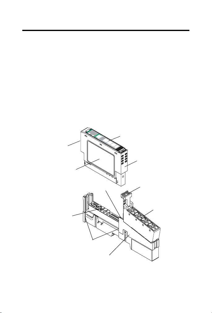
About the Module
This module is a 4-channel 24V dc input module with short-circuit
and open-wire diagnostics.
See the figures to familiarize yourself with major parts of the module,
noting that the wiring base assembly is one of the following, with the
module not being compatible with 1734-TB3, 1734-TB3S, 1734-TOP3,
and 1734-TOP3S bases:
• 1734-TB POINT I/O two-piece terminal base, which includes
the 1734-RTB removable terminal block
• 1734-TOP or 1734-TOPS POINT I/O one-piece terminal bass
odule
M
Status
ork
Netw
:
Status
E
D
Module Locking
Mechanism
Module Wiring Diagram
O
N
Slide-in Writable Label
0
1
2
3
Insertable I/O Module
Publication
DIN Rail Locking Screw (orange)
Mechanical Keying
(orange)
Interlocking Side Pieces
Mounting Base
1734-IN029A-EN-E - January 2007
Removable Terminal
Block Handle
Removable
Terminal Block
Page 7
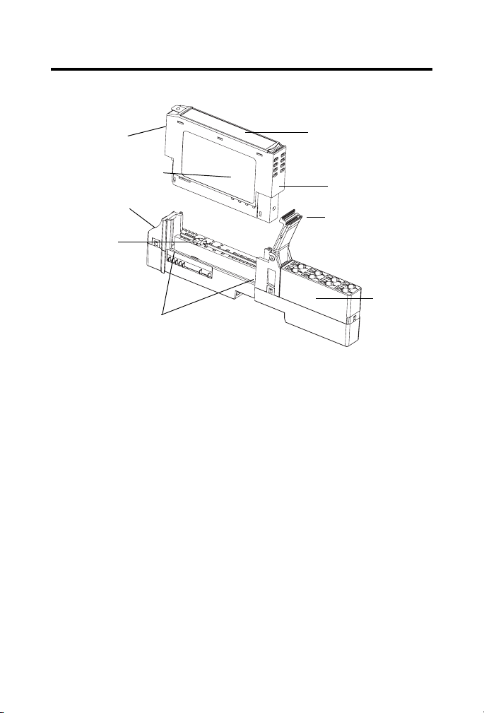
POINT I/O 24V dc Digital Diagnostics Input Module 7
Module Locking
Mechanism
Module Wiring Diagram
DIN Rail Locking
Screw (orange)
Mechanical
Keying (orange)
Interlocking
Side Pieces
Slide-in Writable Label
Insertable
I/O Module
Handle
One-piece
Terminal
Base with
Screw or
Spring
Clamp
44221
Publication
1734-IN029A-EN-E - January 2007
Page 8

8 POINT I/O 24V dc Digital Diagnostics Input Module
Before You Begin
The module supports remove and insert under power, auto-address,
and auto-baud in compliance with the POINTBus backplane. Each
input is a sinking dc input with short-circuit and open-wire detection.
The sensor source voltage is derived from the user auxiliary power
and used as I/O power.
Understand Short-circuit Detection
The sensor source voltage (SSV) for each input is protected against
short circuits. For currents above 200 mA, a fault signal is issued and
the input LED indicator is illuminated solid red. A thermally-actuated
smart-power device or PTC is used as the protection means. On a
per-input basis, the circuit and produced data automatically reset and
SSV energizes upon removal of the short circuit. An individual fault
signal is issued for each shorted SSV condition.
The shorted input LED indicator illuminates red to denote
short-circuit fault status.
See the section on interpreting LED indicators for related information.
When the SSV is loaded to the maximum rated current of 50 mA, a
voltage drop of as much as 2.5V dc can exist between the user
auxiliary power and the SSV connection. For example, for a supply of
10V dc to a sensor with power derived from the SSV, a supply of
12.5V dc is needed at the auxiliary power connection.
Publication
1734-IN029A-EN-E - January 2007
Page 9

POINT I/O 24V dc Digital Diagnostics Input Module 9
Understand Open-wire Detection
Sensor source voltage (SSV) current for each input is monitored.
Monitoring is accomplished in the SSV leg to accommodate the
largest number of sensors possible. For currents below 0.5 mA, a fault
signal is issued and the input's LED indicator blinks red. On a
per-input basis, the circuit and produced data automatically reset
upon removal of the open-wire condition. See the information about
interpreting LED indicators for related information.
By using a configuration tool, you can disable the open- wire
diagnostics on an input-point basis to keep unused input indicators
from turning red and signaling a fault when an input is not in use.
Enabling or disabling input-point level open-wire diagnostics is
implemented via the module’s EDS file, GSD file, or Logix profile and
its firmware.
You can also disable all the open-wire diagnostics, using a single
entry via the software user interface. The default configuration has
all four input channels’ open-wire indication enabled.
If a sensor with a dry contact output is used, wire one side of the
contact to the SSV terminal for the corresponding input. Wire the
other side of the contact to the input. Additionally, place a shunt
resistor in parallel with the contact, at the sensor, to cause greater
than 0.5 mA to be drawn through the SSV terminal at all times.
Install the Mounting Base
To install the mounting base on the DIN rail, proceed as follows.
1. Position the mounting base vertically above the installed units,
for example, adapter, power supply, or existing module.
2. Slide the mounting base down so that the interlocking side
pieces engage the adjacent module or adapter.
Publication
1734-IN029A-EN-E - January 2007
Page 10

10 POINT I/O 24V dc Digital Diagnostics Input Module
Slide the Mounting Base Until Side Pieces Engage
Slide the mounting base until the
interlocking side pieces engage the
adjacent module or adapter.
3. Press firmly to seat the mounting base on the DIN rail until the
mounting base snaps into place.
31586
Publication
1734-IN029A-EN-E - January 2007
Page 11

POINT I/O 24V dc Digital Diagnostics Input Module 11
Install the Module
Install the module before or after base installation. Before installing
the module into the mounting base be sure of this.
• The mounting base is correctly keyed.
• The mounting base locking screw is positioned horizontally
referenced to the base.
Turn the keyswitch to align
the number with the notch.
Notch position 3 is shown.
Be sure the DIN-rail locking screw is
in the horizontal position.
1734-TB base is shown.
44229
Publication
1734-IN029A-EN-E - January 2007
Page 12

12 POINT I/O 24V dc Digital Diagnostics Input Module
Be sure the DIN-rail
locking screw is in
the horizontal
position.
Turn the keyswitch
to align the number
with the notch.
Notch position 1 is
shown.
1734-TOP base is shown.
44228
Publication
1734-IN029A-EN-E - January 2007
Page 13

POINT I/O 24V dc Digital Diagnostics Input Module 13
WARNING
When you insert or remove the module while backplane power
is on, an electrical arc can occur. This could cause an explosion
in hazardous location installations.
Be sure that power is removed or the area is nonhazardous
before proceeding. Repeated electrical arcing causes excessive
wear to contacts on both the module and its mating connector.
Worn contacts may create electrical resistance that can affect
module operation.
To install the module, use this procedure.
1. Use a bladed screwdriver to rotate the keyswitch on the
mounting base clockwise until the number required for the
type of module being installed aligns with the notch in the
base.
2. Be sure the DIN-rail locking screw is in the horizontal
position, noting that you cannot insert the module if the
locking mechanism is unlocked.
3. Insert the module straight down into the mounting base and
press to secure, until the module locks into place.
4. Insert the end opposite the handle into the base unit, noting
this end has a curved section that engages with the wiring
base.
5. Rotate the terminal block into the wiring base until it locks
itself in place.
6. Snap the RTB handle into place on the module, if an I/O
module is installed.
Publication
1734-IN029A-EN-E - January 2007
Page 14

14 POINT I/O 24V dc Digital Diagnostics Input Module
Insert the Module on the Base
Insert the module straight down into the
mounting base.
Hook the RTB end into
the mounting base end
and rotate until it locks
into place.
44011
Publication
1734-IN029A-EN-E - January 2007
Page 15

POINT I/O 24V dc Digital Diagnostics Input Module 15
Install the Removable Terminal Block
WARNING
When you connect or disconnect the removable terminal block
(RTB) with field-side power applied, an electrical arc can occur.
This could cause an explosion in hazardous location
installations.
Be sure that power is removed or the area is nonhazardous
before proceeding.
Read this for information if a removable terminal block (RTB) is
supplied with your wiring base assembly, noting that 1734-TOP and
1734-TOPS bases do not have an RTB.
To insert the RTB, proceed as follows. Note that if you pull up on the
RTB handle to remove the RTB, you can remove and replace the
mounting base as necessary without removing any of the wiring.
1. Insert the end opposite the handle into the base unit, noting
that this end has a curved section that engages with the wiring
base.
2. Rotate the terminal block into the wiring base until it locks
itself into place.
3. If an I/O module is installed, snap the RTB handle into place
on the module.
Wire the Module
See the figure and tables for information about how to wire the
module.
WARNING
If you connect or disconnect wiring while the field-side power is
on, an electrical arc can occur. This could cause an explosion in
hazardous location installations. Be sure that power is removed or
the area is nonhazardous before proceeding.
Publication
1734-IN029A-EN-E - January 2007
Page 16

16 POINT I/O 24V dc Digital Diagnostics Input Module
Module Status
Network Status
Status - Input 0
Status - Input 1
Status - Input 2
Status - Input 3
Input 0
Input 1 SSV 1
Input 2 SSV 2
Input 3 SSV 3
Note that voltage and current are daisychained from either the adapter,
1734-FPD module, or 1734-EP24DC module.
Common connections for three-wire devices require an external wiring
connection. A 1734-CTM module can provide the common connection.
Publication
1734-IN029A-EN-E - January 2007
SSV 0
41974
Page 17

Wiring
Sink Input
POINT I/O 24V dc Digital Diagnostics Input Module 17
Prox
0
In 0
2
In 1 V 1
Prox
4
In 2
6
In 3
V=10/28.8V dc
If a common connection is required (three-wire devices), then a 1734-CTM
V 0
V 2
V 3
1
3
5
7
Prox
Prox
44226
common terminal module can be required.
Channel Terminal Number
Input Common Voltage
00
External
(1)
1
12 3
24 5
36 7
Connect common on three-wire proximity switches.
10/28.8V dc is supplied through the internal power bus.
(1)
Common connections require an external connection, such as a 1734-CTM module.
Publication
1734-IN029A-EN-E - January 2007
Page 18

18 POINT I/O 24V dc Digital Diagnostics Input Module
Configure the Module
Read this section for information about how to communicate with
your module.
I/O messages are sent to (consumed) and received from (produced)
the POINT I/O modules. These messages are mapped into the
processor’s or scanner’s memory. This POINT I/O input module
produces 1 or 2 bytes of input data based on which produced
assembly is selected. The default setup is 2 bytes. It does not
consume I/O data (scanner Tx).
Default Data Map - Produced Assembly Instance 101
Message Size: 2 Bytes
76543210
Produce 0 (Rx) Fault 3Fault 2Fault 1Fault 0Input 3Input 2Input 1Input
Produce 1 (Rx) SC 3 SC 2 SC 1 SC 0 OW 3 OW 2 OW 1 OW 0
Consume (Tx) No consumed data
Where: OW = open wire, SC = short circuit, fault = open wire or short circuit.
Data Map - Produced Assembly Instance 23
0
Message Size: 1 Byte
76543210
Produce 0 (Rx) Fault 3Fault 2Fault 1Fault 0Input 3Input 2Input 1Input
Consume (Tx) No consumed data
Where: Fault = open wire or short circuit.
Publication
1734-IN029A-EN-E - January 2007
0
Page 19

POINT I/O 24V dc Digital Diagnostics Input Module 19
Default Data Map - Configuration Assembly Instance 103
Message Size: 18 Bytes
76543210
Consume 0 Input 0 Off to On Filter Byte 0
Consume 1 Input 0 Off to On Filter Byte 1
Consume 2 Input 0 On to Off Filter Byte 0
Consume 3 Input 0 On to Off Filter Byte 1
Consume 4 Input 1 Off to On Filter Byte 0
Consume 5 Input 1 Off to On Filter Byte 1
Consume 6 Input 1 On to Off Filter Byte 0
Consume 7 Input 1 On to Off Filter Byte 1
Consume 8 Input 2 Off to On Filter Byte 0
Consume 9 Input 2 Off to On Filter Byte 1
Consume 10 Input 2 On to Off Filter Byte 0
Consume 11 Input 2 On to Off Filter Byte 1
Consume 12 Input 3 Off to On Filter Byte 0
Consume 13 Input 3 Off to On Filter Byte 1
Consume 14 Input 3 On to Off Filter Byte 0
Consume 15 Input 3 On to Off Filter Byte 1
Consume 16 Autobaud
Disable
Consume 17 Produced Assembly Instance
Produce (Tx) No produced data
Where: OW = open wire.
Enable
OW3
Enable
OW2
Enable
OW1
Enable
OW0
Publication
1734-IN029A-EN-E - January 2007
Page 20

20 POINT I/O 24V dc Digital Diagnostics Input Module
Interpret the LED Indicators
See the figure and table that show how to interpret LED indicators.
Module Status
Network Status
Status of Input 0
Status of Input 1
Status of Input 2
Status of Input 3
44217
Publication
1734-IN029A-EN-E - January 2007
Page 21

POINT I/O 24V dc Digital Diagnostics Input Module 21
Interpret LED Indicators
Indication Probable Cause Recommended Action
Module Status
Off No power applied to device. Apply power to device.
Green Device operating normally. None.
Flashing Green Device needs commissioning due
to configuration missing,
incomplete or incorrect.
Flashing Red Recoverable fault. 1. Cycle power to device.
Red Unrecoverable fault may require
device replacement.
Flashing Red/Green Device is in self-test. None.
Configure device properly.
2. If condition persists,
replace device.
Replace device.
Publication
1734-IN029A-EN-E - January 2007
Page 22

22 POINT I/O 24V dc Digital Diagnostics Input Module
Indication Probable Cause Recommended Action
Network Status
Off Device is not online.
- Device has not completed
dup_MAC_id test.
- Device not powered - check
module status indicator
Flashing Green Device is on-line but has no
connections in the established
state.
Green Device on-line and has
connections in the established
state.
Flashing Red One or more I/O connections in
timed-out state.
Red Critical link failure - failed
communication device. Device
detected error that prevents it
communicating on the network.
Flashing Red/Green Communication faulted device -
the device has detected a network
access error and is in
communication faulted state.
Apply power to device,
wait for dup_MAC_id to
complete, and correct, as
needed.
None - device is in Idle or
Program mode.
None.
Check for I/O module
failure, and correct, as
needed.
Verify that adapter and
terminal bases are
properly installed, and
reinstall, as needed.
Verify that adapter is
properly installed, and
reinstall, as needed.
Device has received and accepted
an Identify Communication
Faulted Request - long protocol
message.
I/O Status
Off Input is in the off state. None.
Publication
1734-IN029A-EN-E - January 2007
Page 23

POINT I/O 24V dc Digital Diagnostics Input Module 23
Indication Probable Cause Recommended Action
Yellow Input is in the on state. None.
Red Short circuit detected. Check I/O wiring or
terminal base.
Flashing Red Open wire detected. Check I/O wiring or
terminal base.
Remove a Mounting Base
To remove a mounting base, you must first remove any installed
module and the module installed in the base to the right.
1. For a module with a two-piece terminal base, use these steps;
otherwise, use step 2.
a. Remove the removable terminal block (RTB), if wired.
b. Unlatch the RTB handle on the I/O module.
c. Pull on the RTB handle to remove the RTB.
2. Press on the module lock on the top of the module.
3. Pull on the I/O module to remove from the base.
4. Repeat steps 1, 2, 3, and 4 for the module to the right.
5. Lift straight up to remove.
Publication
1734-IN029A-EN-E - January 2007
Page 24

24 POINT I/O 24V dc Digital Diagnostics Input Module
Specifications
POINT I/O 24V dc 4-channel Digital Diagnostics Input Module - 1734-IB4D
Attribute Value
Module Location 1734-TB, 1734-TBS, 1734-TOP, and 1734-TOPS bases
POINTBus Current 50 mA max @ 5V dc
Power Dissipation 0.6 W max @ 28.8V dc
Thermal Dissipation 1.9 BTU/hr max @ 28.8V dc
Isolation Voltage 50Vdc (continuous), Reinforced Insulation Type
Field Power Bus
Supply Voltage
Voltage Range
Dimensions HxWxL, approx. 56 x 12 x 75.5 mm
Terminal Base Screw Torque 0.8 Nm (7 lb-in)
Keyswitch Position 1
Reverse Polarity Protection Yes
On-state Voltage (Von), Min 11V dc
On-state Voltage (Von), Max 28.8V dc (Vmax)
On-state Current (Ion), Min 2.0 mA
On-state Current (Ion), Max 15.0 mA (Imax)
Off-state Voltage (Voff), Min -3V dc
Off-state Voltage (Voff), Max 5V dc
Off-state Current (Ioff), Min 1.5 mA
Input Filter Each input independently settable in 1 us intervals
Off to On Filter, Min 0 us
Tested at 1000 V dc for 60 s, field-side to system
24V dc nom
10…28.8V dc
2.2 x 0.47 x 2.97 in.
(rounded to nearest 333 us).
Default value is 1000 us.
Publication
1734-IN029A-EN-E - January 2007
Page 25

POINT I/O 24V dc Digital Diagnostics Input Module 25
POINT I/O 24V dc 4-channel Digital Diagnostics Input Module - 1734-IB4D
Attribute Value
Off to On Filter, Max 65,535 us
On to Off Filter, Min 0 us
Off to On Filter, Max 65 535 us
Environmental Specifications
Attribute Value
Temperature, operating IEC 60068-2-1 (Test Ad, Operating Cold),
IEC 60068-2-2 (Test Bd, Operating Dry Heat),
IEC 60068-2-14 (Test Nb, Operating Thermal Shock):
-20…55 °C (-4…131 °F)
Temperature, storage IEC 60068-2-1 (Test Ab, Unpackaged Nonoperating Cold),
IEC 60068-2-2 (Test Bb, Unpackaged Nonoperating Dry
Heat),
IEC 60068-2-14 (Test Na, Unpackaged Nonoperating
Thermal Shock):
-40…85°C (-40…185°F)
Relative Humidity IEC 60068-2-30 (Test Db, Unpackaged Damp Heat):
Shock
Operating
Nonoperating
Vibration IEC 60068-2-6 (Test Fc, Operating): 5 g @ 10…500 Hz
ESD Immunity IEC 61000-4-2: 6 kV contact discharges, 8 kV air discharges
Radiated RF Immunity IEC 61000-4-3:
EFT/B Immunity IEC 61000-4-4: ±4 kV at 5 kHz on signal ports
5…95% noncondensing
IEC 60068-2-27 (Test Ea, Unpackaged Shock)
30 g peak acceleration
50 g peak acceleration
10V/m with 1 kHz sine-wave 80%AM from 80…2000 MHz
10V/m with 200 Hz 50% Pulse 100%AM at 900 MHz
10V/m with 200 Hz 50% Pulse 100%AM at 1890 MHz
1V/m with 1 kHz sine-wave 80%AM from 2000…2700 MHz
Publication
1734-IN029A-EN-E - January 2007
Page 26

26 POINT I/O 24V dc Digital Diagnostics Input Module
Environmental Specifications
Attribute Value
Surge Transient Immunity IEC 61000-4-5:
±1 kV line-line (DM) and ±2 kV line-earth (CM) on signal
ports
Conducted RF Immunity IEC 61000-4-6:
Emissions CISPR 11: Group 1, Class A
Enclosure Type Rating
North American Temp Code T5
Wire Size
Wire Category
(1)
Use this Conductor Category information for planning conductor routing. Refer to
Industrial Automation Wiring and Grounding Guidelines, publication 1770-4.1.
10V rms with 1 kHz sine-wave 80%AM from
150 kHz…80 MHz
None (open-style)
2
0.25... 2.5 mm
rated at 75 °C (167 °F ) or greater
1.2 mm (3/64 in.) insulation max
1 - on signal ports
(22...14 AWG) solid or stranded copper wire
(1)
Publication
1734-IN029A-EN-E - January 2007
Page 27

POINT I/O 24V dc Digital Diagnostics Input Module 27
Certifications
Attribute Value
Certifications
(when
product is
marked)
(1)
See the Product Certification link at http://www.ab.com for Declarations of Conformity, Certificates,
and other certification details.
Allen-Bradley, POINT I/O, POINTBus, Rockwell Automation, and TechConnect are trademarks of
Rockwell Automation, Inc.
Trademarks not belonging to Rockwell Automation are property of their respective companies.
C-Tick Australian Radiocommunications Act, compliant with:
AS/NZS CISPR 11; Industrial Emissions
C-UL-us
(1)
UL Listed Industrial Control Equipment, certified for US and
Canada. See UL File E65584.
UL Listed for Class I, Division 2 Group A,B,C,D Hazardous
Locations, certified for U.S. and Canada. See UL File E194810.
CE European Union 89/336/EEC EMC Directive, compliant with:
EN 50082-2; Industrial Immunity
EN 61326; Meas./Control/Lab., Industrial Requirements
EN 61000-6-2; Industrial Immunity
EN 61000-6-4; Industrial Emissions
EN 61131-2; Programmable Controllers (Clause 8, Zone A & B)
Publication
1734-IN029A-EN-E - January 2007
Page 28

Rockwell Automation Support
Rockwell Automation provides technical information on the web to assist you
in using its products. At http://support.rockwellautomation.com
technical manuals, a knowledge base of FAQs, technical and application
notes, sample code and links to software service packs, and a MySupport
feature that you can customize to make the best use of these tools.
For an additional level of technical phone support for installation,
configuration, and troubleshooting, we offer TechConnect Support programs.
For more information, contact your local distributor or Rockwell Automation
representative, or visit http://support.rockwellautomation.com
Installation Assistance
If you experience a problem with a hardware module within the first 24 hours
of installation, please review the information that's contained in this manual.
You can also contact a special Customer Support number for initial help in
getting your module up and running.
United States 1.440.646.3223 Monday – Friday, 8am – 5pm EST
Outside United States Please contact your local Rockwell Automation representative for any
technical support issues.
New Product Satisfaction Return
Rockwell tests all of its products to ensure that they are fully operational when
shipped from the manufacturing facility. However, if your product is not
functioning, it may need to be returned.
United States Contact your distributor. You must provide a Customer Support case number
Outside United States Please contact your local Rockwell Automation representative for return
(see phone number above to obtain one) to your distributor in order to
complete the return process.
procedure.
, you can find
.
Publication 1734-IN029A-EN-E - January 2007 PN 953014-73
Copyright © 2007 Rockwell Automation, Inc. All rights reserved. Printed in the U.S.A.
 Loading...