

Page 1

Installation Instruction
POINT I/O 120/240V ac Expansion Power
Supply
Catalog Number 1734-EPAC
Contents
For See Page
Important User Information 2
Before You Begin 4
Identify the Components 4
Install the ac Expansion Power Supply 6
Remove an ac Expansion Power Supply from the DIN Rail 6
Replace an ac Expansion Power Supply 7
Wire the ac Expansion Power Supply 8
North American Hazardous Location Approval 12
Specifications 13
Current Derating for DIN-Rail Mounting Orientation 16
Publication 1734-IN017A-EN-P - December 2005
Page 2
2 POINT I/O 120/240V ac Expansion Power Supply
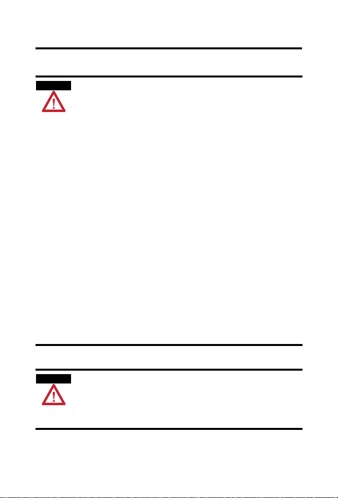
WARNING
IMPORTANT
ATTENTION
SHOCK HAZARD
BURN HAZARD
Important User Information
Solid state equipment has operational characteristics differing from those of electromechanical
equipment. Safety Guidelines for the Application, Installation and Maintenance of Solid State Controls
(Publication SGI-1.1 available from your local Rockwell Automation sales office or online at
http://www.literature.rockwellautomation.com) describes some important differences between solid
state equipment and hard-wired electromechanical devices. Because of this difference, and also because
of the wide variety of uses for solid state equipment, all persons responsible for applying this equipment
must satisfy themselves that each intended application of this equipment is acceptable.
In no event will Rockwell Automation, Inc. be responsible or liable for indirect or consequential damages
resulting from the use or application of this equipment.
The examples and diagrams in this manual are included solely for illustrative purposes. Because of the
many variables and requirements associated with any particular installation, Rockwell Automation, Inc.
cannot assume responsibility or liability for actual use based on the examples and diagrams.
No patent liability is assumed by Rockwell Automation, Inc. with respect to use of information, circuits,
equipment, or software described in this manual.
Reproduction of the contents of this manual, in whole or in part, without written permission of Rockwell
Automation, Inc., is prohibited.
Throughout this manual, when necessary, we use notes to make you aware of safety considerations.
Identifies information about practices or circumstances that can cause an explosion
in a hazardous environment, which may lead to personal injury or death, property
damage, or economic loss.
Identifies information that is critical for successful application and understanding
of the product.
Identifies information about practices or circumstances that can lead to personal
injury or death, property damage, or economic loss. Attentions help you:
• identify a hazard
• avoid a hazard
• recognize the consequence
Labels may be located on or inside the equipment (for example, drive or motor) to
alert people that dangerous voltage may be present.
Publication
Labels may be located on or inside the equipment (for example, drive or motor) to
alert people that surfaces may be dangerous temperatures.
1734-IN017A-EN-P - December 2005
Page 3
POINT I/O 120/240V ac Expansion Power Supply 3
ATTENTION
ATTENTION
Environment and Enclosure
This equipment is intended for use in a Pollution Degree 2 industrial
environment, in overvoltage Category II applications (as defined in
IEC publication 60664-1), at altitudes up to 2000 meters without
derating.
This equipment is considered Group 1, Class A industrial equipment
according to IEC/CISPR Publication 11. Without appropriate
precautions, there may be potential difficulties ensuring
electromagnetic compatibility in other environments due to
conducted as well as radiated disturbance.
This equipment is supplied as open type equipment. It must be
mounted within an enclosure that is suitably designed for those
specific environmental conditions that will be present and
appropriately designed to prevent personal injury resulting from
accessibility to live parts. The interior of the enclosure must be
accessible only by the use of a tool. Subsequent sections of this
publication may contain additional information regarding specific
enclosure type ratings that are required to comply with certain
product safety certifications.
See NEMA Standards publication 250 and IEC publication 60529, as
applicable, for explanations of the degrees of protection provided by
different types of enclosure. Also, see the appropriate sections in
this publication, as well as Industrial Automation Wiring and
Grounding Guidelines, Allen-Bradley publication 1770-4.1, for
additional installation requirements pertaining to this equipment.
POINT I/O is grounded through the DIN rail to chassis ground. Use
zinc plated, yellow-chromated steel DIN rail to assure proper
grounding. Using other DIN rail materials (for example, aluminum or
plastic) which can corrode, oxidize, or are poor conductors can result
in improper or intermittent platform grounding.
Publication
1734-IN017A-EN-P - December 2005
Page 4

4 POINT I/O 120/240V ac Expansion Power Supply
ATTENTION
Preventing Electrostatic Discharge
This equipment is sensitive to electrostatic discharge, which can
cause internal damage and affect normal operation. Follow these
guidelines when you handle this equipment:
• Touch a grounded object to discharge potential static.
• Wear an approved grounding wriststrap.
• Do not touch connectors or pins on component boards.
• Do not touch circuit components inside the equipment.
• Use a static-safe workstation, if available.
• Store the equipment in appropriate static-safe packaging
when not in use.
Before You Begin
Read this manual for information about how to install the 1734-EPAC
POINT I/O 120/240V ac Expansion Power Supply.
Identify the Components
Use the figure to identify the external features of the ac expansion power
supply.
Publication
1734-IN017A-EN-P - December 2005
Page 5
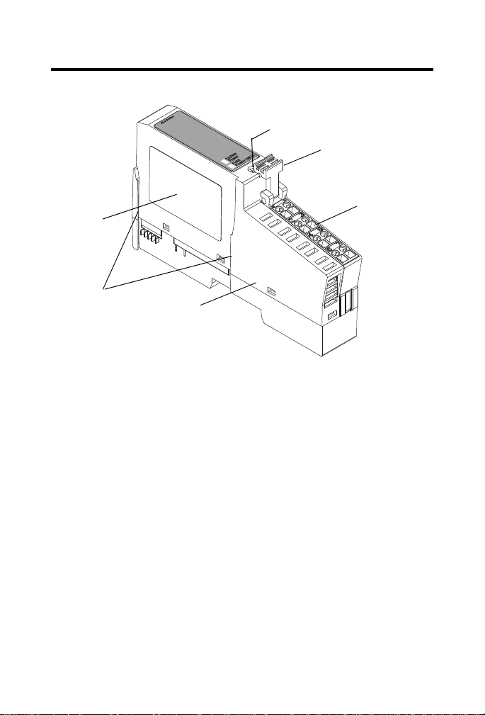
About the ac Expansion Power Supply
1734-EPAC
1734-EPAC Power
Supply
Removable
Terminal
Block (RTB)
RTB Removal Handle
DIN-rail Locking
Screw
Module Label
Interlocking
Side Pieces
The 1734-EPAC ac expansion power supply passes 120/240V ac field power
to the I/O modules to the right of it. This unit extends the backplane bus
power for up to 17 I/O modules to the right of the supply, and creates a new
field-voltage partition segment for driving field devices. The number of I/O
modules supported by this power supply depend on the current required for
each module and the DIN-rail mounting position. Do not exceed the current
draw as shown in the specifications.
The ac expansion power supply also separates field power from I/O modules
to the left of the unit, effectively providing functional and logical partitioning
for:
POINT I/O 120/240V ac Expansion Power Supply 5
• separating field power between input and output modules.
• grouping modules to perform a specific task or function.
Publication
1734-IN017A-EN-P - December 2005
Page 6

6 POINT I/O 120/240V ac Expansion Power Supply
ATTENTION
WARNING
You can use multiple ac expansion power supplies with POINT I/O adapters
to assemble a full system. For instance, if you are using the 1734-ADN
adapter, you may use an ac expansion power supply to add additional modules
in 4 to 17 module increments. For example, if you had a 36 module system
with a 1734 POINT I/O adapter, you would have two 1734-EPAC ac
expansion power supplies to provide more PointBus current for modules to
the right of the supply.
You can only use the 1734-EPAC ac expansion power supplies with the
1734 POINT I/O adapters, such as the 1734-ADN, 1734-ADNX,
1734-APB, 1734-ACNR, and 1734-AENT adapters.
Do not use with the 1734-PDN module or with POINTBlock modules.
Install the ac Expansion Power Supply
To install the power supply on the DIN rail, proceed as follows.
1. Position the power supply vertically above the DIN rail.
2. Engage the interlocking side pieces with the unit on the left.
3. Press down firmly to install the power supply on the DIN rail.
The locking mechanism will lock the power supply to the DIN rail.
Remove an ac Expansion Power Supply from the DIN Rail
1. To remove ac expansion power supply from the DIN rail, pull up on
the RTB removal handle to remove the terminal block.
When you insert or remove the power supply while backplane
power is on, an electrical arc can occur. This could cause an
explosion in hazardous location installations.
Be sure that power is removed or the area is nonhazardous before
proceeding. Repeated electrical arcing causes excessive wear to
contacts on both the power supply and its mating connector.
Worn contacts may create electrical resistance that can affect
power supply operation.
Publication
1734-IN017A-EN-P - December 2005
Page 7

POINT I/O 120/240V ac Expansion Power Supply 7
WARNING
When you connect or disconnect the removable terminal block (RTB)
with field-side power applied, an electrical arc can occur. This could
cause an explosion in hazardous location installations. Be sure that
power is removed or the area is nonhazardous before proceeding.
2. Remove the module to the right of the power supply from its base
unit.
3. Use a small-bladed screwdriver to rotate the DIN-rail locking screw to
a vertical position.
This releases the locking mechanism.
4. Lift straight up to remove.
Replace an ac Expansion Power Supply
1. Remove the module to the right of the ac expansion power supply
from its base unit.
2. Position the ac expansion power supply vertically above the DIN rail.
3. Slide the power supply down allowing the interlocking side pieces to
engage the adjacent modules (both left and right sides).
4. Press firmly to seat the power supply on the DIN rail.
The power supply locking mechanism will snap into place.
5. Reinsert the module into the base to the right of the power supply.
Publication
1734-IN017A-EN-P - December 2005
Page 8

8 POINT I/O 120/240V ac Expansion Power Supply
WARNING
System
Power
Field
Power
1734-EPAC
1734EPACfrt
L2/N
L1
NC
L2/N
L1
NC
NC = No Connection
PE = Protective Earth Ground
L2/N = Neutral
L1 = 120/240V ac
PE
PE
Wire the ac Expansion Power Supply
120/240V ac Wiring
Publication
1734-IN017A-EN-P - December 2005
If you connect or disconnect wiring while field side power is on, an
electrical arc can occur. This could cause an explosion in hazardous
location installations.
Be sure that power is removed or the area is nonhazardous before
proceeding.
Page 9

POINT I/O 120/240V ac Expansion Power Supply 9
ATTENTION
IMPORTANT
NC NC
L2/N
L1 L1
L2/N
V ac
L1 = 120/240V ac,
L2/N = Neutral
PE = Protective Earth Ground
This ac supply will be
connected to the internal
PEPE
3
5
7
01
2
4
6
42513A
Connect ground wire to PE
terminal.
Connect Terminal Terminals (For Continuing Power)
L1 (120/240V ac) 6 7
L2/N (Neutral) 4 5
PE (Protective Earth Ground) 2 3
120/240V ac becomes the internal power bus for modules to the right.
Use the 1734-EPAC ac expansion power supply only with Adapter
Class products.
The 1734-EPAC ac expansion power supply can only be used with
POINT I/O adapters.
Publication
1734-IN017A-EN-P - December 2005
Page 10

10 POINT I/O 120/240V ac Expansion Power Supply
0101 01 01 0101 0101
Adapter
Status
DeviceNet
Status
PointBus
Status
1734-ADN
DeviceNet
Power
System
Power
1734-EPAC
Field
Power
System
Power
0101 0101
1734-EPAC
Field
Power
System
Power
1734-EPAC
1734-ADN
12/24V dc Digital Supply
IB 2IB 4OB2EOB
4E
OA 2OW
2
120V ac Supply
240V ac Supply
1734-EPAC
IM 2OW 2OX
2
41970C
IA
2
IB
2
Partitioning Examples
Functional
Publication
1734-IN017A-EN-P - December 2005
Page 11

Logical
0101 01 01 0101 0101
Adapter
Status
DeviceNet
Status
PointBus
Status
1734-ADN
DeviceNet
Power
System
Power
1734-EPAC
Field
Power
System
Power
1734-EPAC
1734-ADN
24V dc Supply
41970D
IB 2OB
2E
OW
2
IE 2COE
2
IA
2
OA
2
120V ac Supply
POINT I/O 120/240V ac Expansion Power Supply 11
Publication
1734-IN017A-EN-P - December 2005
Page 12

12 POINT I/O 120/240V ac Expansion Power Supply
WARNING
AVERTISSEMENT
North American Hazardous Location Approval
The following information applies when
operating this equipment in hazardous
locations:
Products marked CL I, DIV 2, GP A, B, C, D are suitable for
use in Class I Division 2 Groups A, B, C, D , hazardous
locations and nonhazardous locations only. Each product
is supplied with markings on the ra ting nameplate
indicating the hazardous location t emperature code.
When combining products within a system, the most
adverse temperature code (lowest “T” number) may be
used to help determine the overall t emperature code of
the system. Combinations of equipment in your system
are subject to investigation by the local Au thority Having
Jurisdiction at the time of installation.
EXPLOSION HAZARD -
• Do not disconnect equipment
unless power has been removed or
the area is known to be
nonhazardous.
• Do not disconnect connections to
this equipment unless power has
been removed or the area is known
to be nonhazardous. Secure any
external connections that mate to
this equipment by using screws,
sliding latches, threaded
connectors, or other means
provided with this product.
• Substitution of components may
impair suitability for Class I,
Division 2.
• If this product contains batteries,
they must only be changed in an
area known to be nonhazardous.
Informations sur l’utilisation de cet
équipement en environnements dangereux:
Les produits marqués CL I, DIV 2, GP A, B, C, D ne
conviennent qu’à une utilisation en environnem ents de
Classe I Division 2 Groupes A, B, C, D dangereux et non
dangereux. Chaque produit est livré avec des marquages sur
sa plaque d’identification qui indiquent le code de
température pour les environnem ents dangereux. Lorsque
plusieurs produits sont combinés dans un système , le code
de température le plus défavorabl e (code de température le
plus faible) peut être utilisé pour déter miner le code de
température global du système. Les combinaisons
d’équipements dans le système sont sujettes à inspection
par les autorités locales qualifiées au moment de
l’installation.
RISQUE D’EXPLOSION –
• Couper le courant ou s’assurer que
l’environnement est classé non
dangereux avant de débrancher
l'équipement.
• Couper le courant ou s'assurer que
l’environnement est classé non
dangereux avant de débrancher les
connecteurs. Fixer tous les
connecteurs externes reliés à cet
équipement à l'aide de vis, loquets
coulissants, connecteurs filetés ou
autres moyens fournis avec ce
produit.
• La substitution de composants peut
rendre cet équipement inadapté à
une utilisation en environnement de
Classe 1, Division 2.
• S’assurer que l’environnement est
classé non dangereux avant de
changer les piles.
Allen-Bradley, POINT I/O, and POINTBus are trademarks of Rockwell Automation, Inc.
Trademarks not belonging to Rockwell Automation are property of their respective companies.
Publication
1734-IN017A-EN-P - December 2005
Page 13

POINT I/O 120/240V ac Expansion Power Supply 13
Specifications
Specifications - 120/240V ac Expansion Power Supply, Cat. No. 1734-EPAC
I/O Module Capacity 12 modules typical (depending on current draw and orientation
Input Voltage Rating 120/240V ac nom, 50…60 Hz
Field Side Power
Requirements
Inrush Current 2 A max for 6 ms
Indicators 1 green field power status indicator
of modules; 4 to 17 based on module current requirements total not to exceed 1.3 A) (for example, 5 modules at 0.220 A;
17 modules at 0.075 A)
Cat. No. PointBus Current Requirements
1734-IB2 75 mA
1734-IB4 75 mA
1734-IB8 75 mA
1734-IV2 75 mA
1734-IV4 75 mA
1734-OB2 75 mA
1734-OB4 75 mA
1734-OB8 75 mA
1734-OB2E 75 mA
1734-OB2EP 75 mA
1734-OB4E 75 mA
1734-OB8E 75 mA
1734-OV2E 75 mA
1734-OV4E 75 mA
1734-OW2 80 mA
1734-OX2 100 mA
1734-IE2C 75 mA
1734-OE2C 75 mA
1734-IE2V 75 mA
1734-OE2V 75 mA
1734-IA2 75 mA
1734-IM2 75 mA
1734-OA2 75 mA
1734-IJ2 160 mA
1734-IK2 160 mA
1734-IR2 220 mA
1734-IT2I 175 mA
1734-SSI 110 mA
1734-VHSC5 180 mA
1734-VHSC24 180 mA
1734-232ASC 75 mA
1734-485ASC 75 mA
85…264V ac range
120V ac at 200 mA max
240V ac at 100 mA max
1 green 5V system power indicator
Publication
1734-IN017A-EN-P - December 2005
Page 14

14 POINT I/O 120/240V ac Expansion Power Supply
POINTBus Output Current Horizontal DIN rail mounting -
Input Overvoltage Protection MOV and fuse protected
Interruption Output voltage will stay within specifications when input
Module Location Between I/O modules in 1734 system
Limitations Use with POINT I/O adapters only
Power Consumption 15.1 W max @ 264V ac
Power Dissipation 8.4 W max @ 264V ac
Thermal Dissipation 28.7 BTU/hr max @ 264V ac
Isolation Voltage 264V continuous
Field Power Bus
Dimensions (HxWxL) Metric
Environmental Conditions
Supply Voltage
Voltage Range
Supply Current
Imperial
Temperature, Operating IEC 60068-2-1 (Test Ad, Operating Cold),
Temperature, Storage IEC 60068-2-1 (Test Ab, Unpackaged Nonoperating Cold),
Relative Humidity IEC 60068-2-30 (Test Db, Unpackaged Nonoperating
Shock
Vibration IEC 60068-2-6, (Test Fc, Operating)
Operating
Nonoperating
1.3 A at 5.2V dc
Vertical DIN rail mounting -
1.0 A at 5.2V dc
drops out for 10 ms at 85V ac with max load.
Breaks field power bus
Tested to withstand 3250V dc for 60 s
120…240V ac nom, 50…60 Hz
85…264V ac range
10 A max
76.2 x 25.4 x 133.4 mm
3.00 x 1.00 x 5.25 in.
IEC 60068-2-2 (Test Bd, Operating Dry Heat),
IEC 60068-2-14 (Test Nb, Operating Thermal Shock):
-20…55 °C (-4…131 °F)
IEC 60068-2-2 (Test Bb, Unpackaged Nonoperating Dry Heat),
IEC 60068-2-14 (Test Na, Unpackaged Nonoperating Thermal
Shock):
-40…85 °C (-40…185 °F)
Damp Heat):
5…95% noncondensing
IEC 60068-2-27 (Test Ea, Unpackaged Shock)
30 g
50 g
5 g @ 10…500 Hz
Publication
1734-IN017A-EN-P - December 2005
Page 15

POINT I/O 120/240V ac Expansion Power Supply 15
ESD Immunity IEC 61000-4-2:
6 kV contact discharges
8 kV air discharges
Radiated RF Immunity IEC 61000-4-3:
10V/m with 1 kHz sine-wave 80% AM from 30…2000 MHz
10V/m with 200 Hz 50% pulse 100% AM at 900 MHz
10V/m with 200 Hz 50% pulse 100% AM at 1890 MHz
EFT/B Immunity IEC 61000-4-4:
±4 kV at 5 kHz on power ports
Surge Transient Immunity IEC 61000-4-5:
±1 kV line-line (DM) and ±2 kV line-earth (CM) on power ports
Conducted RF Immunity IEC 61000-4-6:
10V rms with 1 kHz sine-wave 80% AM from
150 kHz…80 MHz
Emissions CISPR 11
Enclosure Type Rating None (open-style)
Voltage Variation 30% dips for 1 period at 0 ° & 180 ° on ac supply ports
Conductors Wire Size
Terminal Base Screw Torque 0.8 Nm (7 lb-in)
Field Wiring Terminations 0 - No Connection 1 - No Connection
Weight Metric
Category
Imperial
Group 1, Class A
60% dips for 5 and 50 periods on ac supply ports
±10% fluctuations for 15 minutes on ac supply ports
>95% interruptions for 250 periods on ac supply ports
14…22 AWG (2.5…0.34 mm2) - solid or stranded copper wire
rated at 75 °C or greater
1.2 mm (3/64 inch) insulation maximum
(1)
1
on power ports
2 - Protective Earth Ground 3 - Protective Earth Ground
4 - L2/N 5 - L2/N
6 - L1 7 - L1
182 g
6.40 oz
Publication
1734-IN017A-EN-P - December 2005
Page 16

Certifications (When Product
1.3
1.0
0.5
Horizontal =
1.3 A
Vertical =
1 A
85 120 264
Voltage (V ac)
Current (A)
240
is Marked)
1 Use this conductor category information for planning conductor routing as described in Industrial
2 See the Product Certification link at www.ab.com for Declaration of Conformity, Certificates, and
(2)
Automation Wiring and Grounding Guidelines, publication 1770-4.1.
other certification details.
CULUS UL Listed Industrial Control Equipment,
certified for US and Canada
CULUS UL Listed for Class I, Division 2, Groups A, B,
C and D Hazardous locations, certified for US
and Canada
CE
European Union 89/336/EEC EMC Directive,
compliant with:
EN 50082-2; Industrial Immunity
EN 61326; Meas./Control/Lab., Industrial
Requirements
EN 61000-6-2; Industrial Immunity
EN 61000-6-4; Industrial Emissions
C-Tick Australian Radiocommunications Act
compliant with AS/NZS CISPR 11, Industrial
Emissions
Current Derating for DIN-Rail Mounting Orientation
Publication 1734-IN017A-EN-P - December 2005 PN 957782-81
Copyright © 2005 Rockwell Automation, Inc. All rights reserved. Printed in Singapore.
 Loading...