

Page 1
Installation instructions
The Wireless VITRON is an advanced microprocessor
based Acoustic Glass Break detector. Using advanced
glass-breaking pattern analysis of both Low Frequency
"Flex" & High Frequency "Shatter" channels, the
Wireless VITRON detects the breaking of most
common types of framed glass panes while ignoring
false alarms
Main Features
• Up to 9m detection range
• Suitable for most common glass types: plate,
tempered, laminated and wired glass
• Minimum size for all types of glass: 30cm x 30cm
(12'' x 12'').
• Wall and Front cover Tamper protection
Type of glass Thickness
Plate
Tempered
Laminated
Wired 6.4 mm (1/4'')
• Wireless VITRON will not alarm if glass pane is
broken from inside or glass is dropped on floor.
• Full remote test using RG-65 Glass Break Simulator,
without the need to open the unit
• Optional ceiling/wall mount swivel adaptor for
optimal mounting and performance (supplied w i th
the Wireless VITRON).
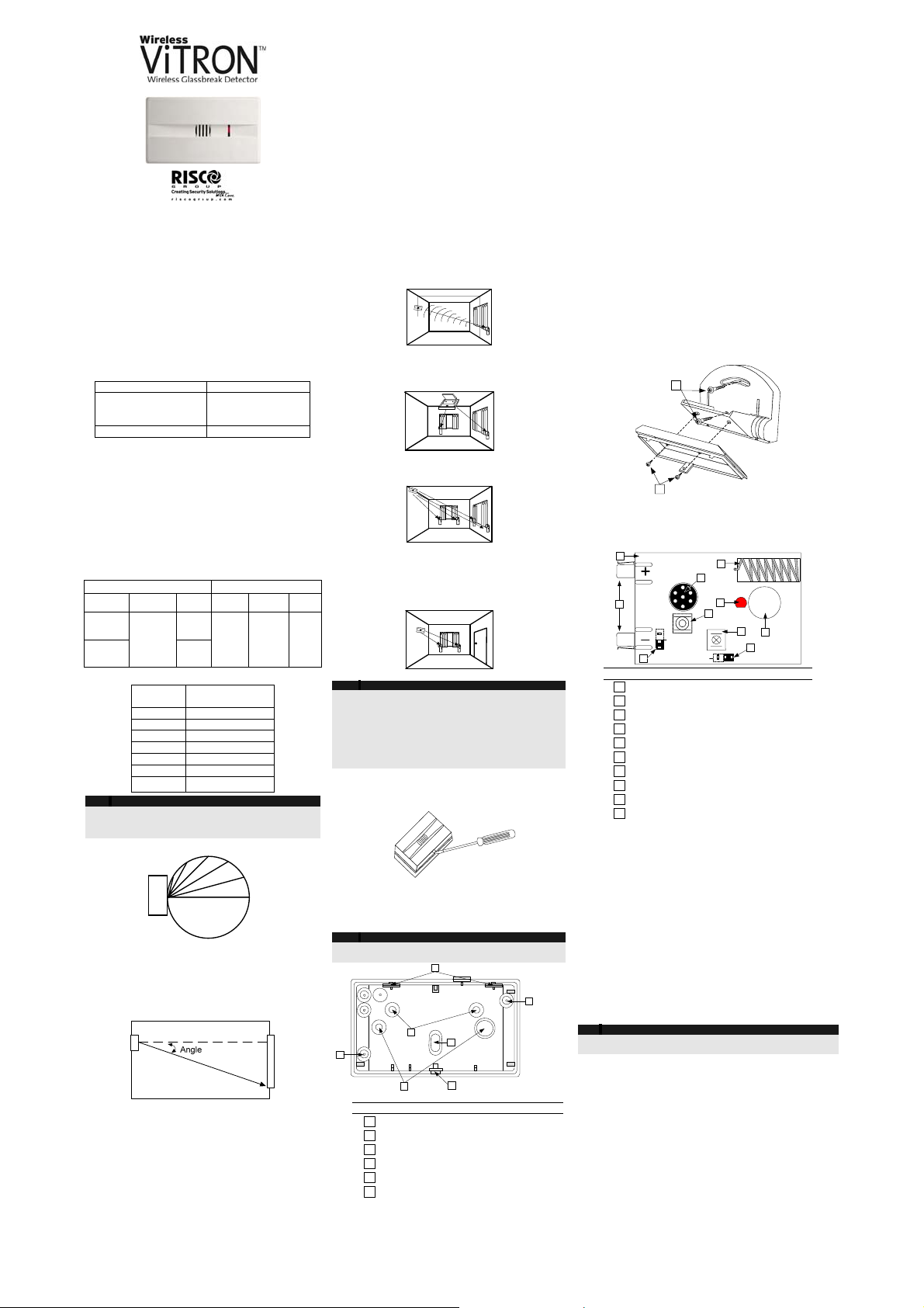
2. Installation Procedure
3.2 mm – 6.4mm
(1/8''-1/4'')
Range of coverage:
Wireless VITRON range of coverage depends on the type
of glass (see Table 1) and the installation angle between
the Wireless VITRON and the glass (see Fig 1)
Minimum
50x50cm
(20"x20")
Minimum
30x30cm
(12''x12'')
Plate Tempered, Laminated, Wired,
Size Thickness Max.
3.2 – 6.4mm
(1/8''-1/4'')
Size Thickness Max.
Range
9m (30ft)
Minimum
30x30cm
(12''x12'')
6m (20ft)
6.4mm
(1/4'')
Range
6m
(20ft)
Table 1: Wireless VITRON range of coverage
Angle
(degrees)
0 10
12 95
30 87
45 70
60 50
75 25
Note:
To improve detection, It is highly recommended to use
a swivel adaptor, especially for ceiling and wall
installations
Fig 1: Percentage of Maximum Range as a function of
angle between Wireless VITRON and glass.
Verify that the distance between the Wireless VITRON
and the furthest point on the protected glass does not
exceed the maximum specified range taking into
account the reduced range due to angle (see Fig 2).
90 0
WIRE LE S S
VIT RON
Fig 2: Angle between Wireless VITRON and glass
60°
75°
Percent of
maximum range
45°
30°
15°
0°
Other factors affecting range:
• There should be no obstructions between the
Wireless VITRON and the protected glass.
• Curtains and blinds may reduce the effective range.
• Sound absorbing materials in the protected area
may reduce the range.
RISCO Group Limited Warranty
RISCO Group and its subsidiaries and affiliates ("Seller") warrants its products to be free from defects in materials and workmanship under normal
use for 24 months from the date of production. Because Seller does not install or connect the product and because the product may be used in
conjunction with products not manufactured by the Seller, Seller can not guarantee the performance of the security system which uses this
product. Sellers' obligation and liability under this warranty is expressly limited to repairing and replacing, at Sellers option, within a reasonable
time after the date of delivery, any product not meeting the specifications. Seller makes no other warranty, expressed or implied, and makes no
warranty of merchantability or of fitness for any particular purpose. In no case shall seller be liable for any consequential or incidental damages for
breach of this or any other warranty, expressed or implied, or upon any other basis of liability whatsoever. Sellers obligation under this warranty
shall not include any transportation charges or costs of installation or any liability for direct, indirect, or not be compromised or circumvented; that
the product will prevent any persona; injury or property loss by intruder, robbery, fire or otherwise; or that the product will in all cases provide
adequate warning or protection. Buyer understands that a properly installed and maintained alarm may only reduce the risk of intruder, robbery or
fire without warning, but is not insurance or a guaranty that such will not occur or that there will be no personal injury or property loss as a result.
Consequently seller shall have no liability for any personal injury, property damage or loss based on a claim that the product fails to give warning.
However, if seller is held liable, whether directly or indirectly, for any loss or damage arising from under this limited warranty or otherwise,
regardless of cause or origin, sellers maximum liability shall not exceed the purchase price of the product, which shall be complete and exclusive
remedy against seller. No employee or representative of Seller is authorized to change this warranty in any way or grant any other warranty.
WARNING: This product should be tested at least once a week.
CAUTION: Risk of explosion if battery is replaced by an incorrect type. Dispose of used batteries according to local regulations
For optimal performance the Wireless VITRON should
be mounted as nearly opposite to the glass area to be
protected, as shown in Fig 3.
• Opposite Wall –Mounted (For optimal results,
Wireless VITRON is centered opposite glass, see
Fig. 3).
VITRON
• Ceiling Mounted (for optimal results Wireless
VITRON is centered and directed towards protected
glass, using the supplied swivel adaptor, see fig. 4).
Fig. 3
5. Swivel Mounting 3. Mounting Location 1. General Description
When installing the Wireless VITRON with the supplied swivel
mounting adaptor, maximum installation flexibility and
performance is achieved.
To install the swivel mounting adaptor perform the following:
1. Remove the PCB from the Wireless VITRON back plate
2. Open the swivel mounting adaptor knockouts (4, Fig 7).
3. Attach the swivel mounting adaptor to the back plate using
the two supplied screws (1, Fig 8).
4. Mount the Wireless VITRON on the required location (wall
or ceiling) using the supplied screws (2, Fig 8). Do not
tighten the screws.
5. Adjust the detector so it will face the protected glass.
6. Tighten the bolts to the final torque.
2
VITRON
• Corner Mounted (choose corner opposite glass to
be protected see fig. 5).
• Side wall – mounted (not recommended due to the
fact that the Wireless VITRON is not opposite the
glass - see range versus angle diagram (Fig 2). Test
detection carefully at both ends of glass using
RG-65 Tester (see fig. 6).
Notes:
Do not mount Wireless VITRON on same wall as the
protected glass.
Avoid installing the Wireless VITRON near sources of loud
noise or vibrations (air conditioners, fans, compressors,
stereos, etc).
Avoid defining the Wireless VITRON as a 24 hour zone.
The Wireless VITRON should always be installed in addition
to standard motion detectors.
Fig. 4
VITRON VITRON
Fig. 5
VITRON VITRON
Fig. 6
4. Mounting
1. Open the Wireless VITRON cover using a flat
screwdriver.
2. Open the required mounting knockouts, according to
the type of installation (corner, flat or swivel
mounting, see Fig. 7)
3. Use the detector's back plate as a template and
mark the drilling holes on the required position.
Notes:
Remove the PCB only if corner mounting or optional swivel
mounting adaptor is used.
1
Fig 7: Wireless VITRON Mounting Knockouts
# Description
1
2
3
4
5
6
4. If a back tamper protection is required open the back
tamper knockout (3, Fig. 7)
5. Secure the back plate to the wall using the supplied
screws. Snap back the PCB (if removed).
Insert battery in place according to the correct polarity
(polarity marks - on PCB).
5
4
2
Corner mounting knockout
Wall/Flat mounting knockout
Back tamper knockout
Swivel mounting adaptor knockouts
Cover attaching notches
Snap and fastening screw
VITRON
VITRON
VITRON
6. PCB Main Components
7. Transmitter/Receiver Communication link setup
The Wireless VITRON has 3 operation modes:
Normal : Any loud sounds such as clapping, whistling or key-
jingling should produce a flash of the VITRON 's LED. This
verifies that the Wireless VITRON is active. During active
supervision, there is no transmission. To save power
consumption the LED is activated up to 800 times per day.
Alarm: On detection of framed glass being broken from
outside the LED will light continuously for 2 seconds and an
alarm transmission is sent
1
Fig. 8
1
2
# Description
1
2
3
4
5
6
7
8
9
10
© RISCO
7
BATT1
J3
3
PCB
Battery holding holders
J3 – RF Power selector
J4 – Time supervision selector
Front Cover tamper switch
Back Plate cover tamper switch
Microphone
Antenna
Indication LED
Positioning hole
RF POWER
HIGH/LOW
SW2
SW1
SUPERVISION
15/65 Min.
6
8
ANTENNA
LED
9
5
10
4
J4
Test: See test paragraph
8. Testing the Wireless VITRON
Testing under Test mode
1
3
Testing should be performed using RISCO Group's RG65
Glass Break Simulator which has been specially designed
and calibrated to give accurate range test results.
Note:
All tests should be conducted under worst case conditions. All
sounds should be generated behind curtains or blinds.
Step 1: Entering the test mode
6
The Wireless VITRON enter the test mode if one of the
following is performed:
1. After closing the front cover - the Wireless VITRON will
enter into test mode for 2 minutes.
2. Using the RG65 tester - Position the tester at a distance of
1 meter from the Wireless VITRON . Set the lower selector
switch on the RG65 tester to CODE setting and press the
operation button on the tester. The Wireless VITRON will
blink once every 3 seconds, lasting for a period of two
minutes.
Step 2: High frequency (audio) test
Position the Glass Break Simulator at the farthest point on the
protected glass and face it into the room. Set lower selector to
GLASS setting and upper to type of glass to be simulated.
Generate glass-break sound by pressing operating button.
Verify that the Wireless VITRON LED is lit for 2 seconds and
ALARM message is transmitted while the red LED is on.
Page 2
Step 3: Environmental Test
This test is performed to verify interference produced
by environmental conditions or facilities.
To perform the test, operate all devices in the
protected region that may interfere with the detector,
including air conditioners, fans, radios etc.
Observe the wireless VITRON and note any
disturbances. If disturbances occur, re - positions the
unit in a different position and re- test.
Turn all noise generating equipment off and wait until
unit returns to NORMAL mode.
Note:
The Wireless VITRON will return to NORMAL mode
after two minutes. Setting the "CODE" switch and
pressing the "Manual" button at any time will initiate
another two minutes Test Mode.
Step 4: User test
The Wireless VITRON can be tested by the installer or
the user while in normal mode by clapping or whistling
or key- jingling under the detector. The led will flash. No
report will be established.
9. Jumpers settings
Description Jumper position
J3 Power High/Low
J4 Supervision
Defines the Glass
break supervision time
Low
power
default
For FCC
only
On
15 Min
High
Power
Off
65 Min
10. Technical Specifications
Electrical
Current consumption
(standby)
Current consumption
(Alarm transmission)
Modulation type ASK
Battery life 3 years, at 65 minutes
Supervision
transmission
Address codes 16 Millions
Range (loss) 300m (1000 feet)
Voltage
requirements
Frequency GT74023 - 868.65MHz
Physical
Size
(LxWxD)
Environmental
Operating/Storage
temperature
RF immunity 20V/m (80MHz to 2GHz)
* Specifications are subject to change without prior
notice
22 uA at 3 VDC, without
acoustic signal
10 mA at 3 VDC
(Max. with LED OFF)
15 mA at 3 VDC
(Max. with LED ON)
supervision
Every 15/65 minutes.
CR123A 3VDC Lithium
Batteries
87 x 50.7 x 28.6 mm
(3.4 x 2.0 x 1.1 in.)
0°C to 50°C (-32°F to 122°F)
11. Ordering Information
Part Number Description
RWT6G086800A 868.65MHz
RWT6G043300A 433.92MHz
Note: The detector contains a swivel
FCC Note
This equipment has been tested and found to comply with
the limits for a Class B digital device, pursuant to part 15
of the FCC Rules.
These limits are designed to provide reasonable protection
against harmful interference in a residential installation.
This equipment generates uses and can radiate radio
frequency energy and, if not installed and used in
accordance with the instructions, may cause harmful
interference to radio communications. However, there is
no guarantee that interference will not occur in a particular
installation. If this equipment does cause harmful
interference to radio or television reception, which can be
determined by turning the equipment on and off, the user
is encouraged to try to correct the interference by one or
more of the following measures:
Ê Reorient or relocate the receiving antenna.
Ê Increase the separation between the equipment and
Ê Connect the equipment into an outlet on to a different
Ê Consult the dealer or an experienced radio/TV
Changes or modifications to this equipment which are not
expressly approved by the party responsible for
compliance (RISCO Group's.) could void the user's
authority to operate the equipment.
FCC ID: JE4RWT6G Valid for P/N
IC: 6564-RWT6G Valid for P/N GT74023
the receiver.
circuit from that to which the receiver is connected.
technician for help.
GT74023
Contacting RISCO Group
RISCO Group is committed to customer service and product support. You can contact us through our website
(www.riscogroup.com, www.riscogroup.co.uk) or as follows:
United Kingdom
Tel: +44-161-655-5500
sales@riscogroup.co.uk
technical@riscogroup.co.uk
Italy
Tel: +39-02-66590054
info@riscogroup.it
support@riscogroup.it
Spain
Tel: +34-91-490-2133
sales-es@riscogroup.com
support-es@riscogroup.com
France
Tel: +33-164-73-28-50
sales-fr@riscogroup.com
support-fr@riscogroup.com
USA
Tel: +305-592-3820
sales@riscogroupusa.com
support@riscogroupusa.com
Brazil
Tel: +55-11-3661-8767
sales-br@riscogroup.com
support-br@riscogroup.com
China
Tel: +86-21-52-39-0066
sales-cn@riscogroup.com
support-cn@riscogroup.com
Poland
Tel: +48-22-500-28-40
Fax: +48-22-500-28-41
Poland@riscogroup.com
Belgium
Tel: +32-2522-7622
sales-be@riscogroup.com
support-be@riscogroup.com
Israel
Tel: +972(0)3-963-7777
info@riscogroup.com
support@riscogroup.com
All rights reserved.
No part of this document may be reproduced in any form without prior written permission from the publisher.
© RISCO Group 06/08
5INT6G
 Loading...