

Page 1
Wireless PIR Outdoor Detector
Rivelatore PIR da esterno via radio
Détecteur PIR extérieur sans fil
Detector de Exterior PIR Inalámbrico
Detector Infravermelho Passivo Externo Sem Fio
Draadloze PIR-buitendetector
English
Italiano
Español
Français
Português
WL T312
Installation Instructions
Istruzioni per l’installazione
Manuel d'installation
Instrucciones de Instalación
Instruções para Instalação
Installatie handleiding
Nederlands
Page 2
2 Installation Manual
Page 3

WL T312 - Wireless PIR Outdoor Detector
Table of Contents
Installation..............................................................................................................................4
Introduction............................................................................................................................4
Mounting.................................................................................................................................4
Mounting Considerations......................................................................................................4
Wall Mount Installation.........................................................................................................6
Flat Mounting:......................................................................................................................6
45° angle Mounting (Left side mounting):.............................................................................6
Changing Back Tamper position: .........................................................................................7
Back Tamper Terminal Wiring...............................................................................................7
DIP Switch Settings................................................................................................................7
Detection Range Adjustment.................................................................................................8
Walk test .................................................................................................................................9
LED Display............................................................................................................................9
Operational Modes.................................................................................................................9
Transmitter/Receiver Communication link setup.................................................................9
Optional Swivel Installation (Not Supplied) ........................................................................10
Wall Mounting ....................................................................................................................10
Replacing Lenses................................................................................................................. 12
Technical Specification........................................................................................................13
Ordering Information............................................................................................................13
Accessory Kits .....................................................................................................................13
English
Installation Manual 3
Page 4
Installation
Introduction
RISCO Group's WL T312 is a unique detector with signal processing based on two Passive
Infrared (PIR) channels. The WL T312 has an adjustable detection range. The detector is
compatible with all RISCO Group Wireless and Hybrid systems.
The following instructions describe the installation of the WL T312.
Mounting
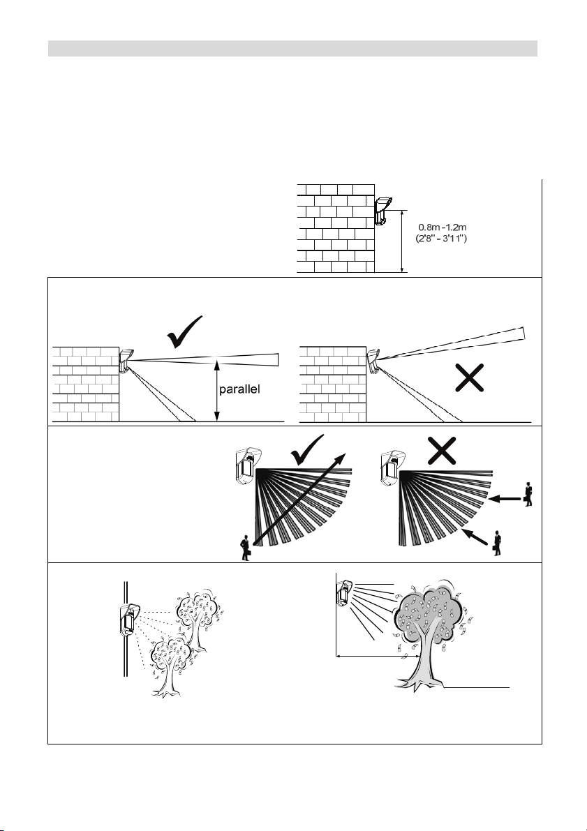
Mounting Considerations
1. Installation Height: 0.8m - 1.2m
(2'8" – 3'11")
Typical Installation Height: 1m (3'3")
2. To ensure maximum operational reliability, install the detector perpendicular to the ground so
that the upper detection area is parallel to the ground.
3. For optimum detection,
select a location that is likely
to intercept an intruder
moving across the coverage
pattern.
With moving object s
keep distance of
4. Avoid pointing the detector to moving
objects (swaying trees, bushes etc.)
4 Installation Manual
minimum 5 meters (16')
5. Ensure any objects do not obstruct the field
of view. Pay attention to growing trees or
bushes, plants with big moving leaves etc.
5m (16')
Out of
Detection Range
Page 5
Installing the WL T312 detector in challenging situations
In the following situations, rapid and significant infrared radiation changes can happen in both
PIR channels together, resulting in false alarms and therefore care should be taken.
1. Situations in which metal and/or glass objects measuring over 70cm (2’4”) in height from the
ground are in the field of view of the detector (cars, metal gates, shutters, metal walls,
windows, etc.)
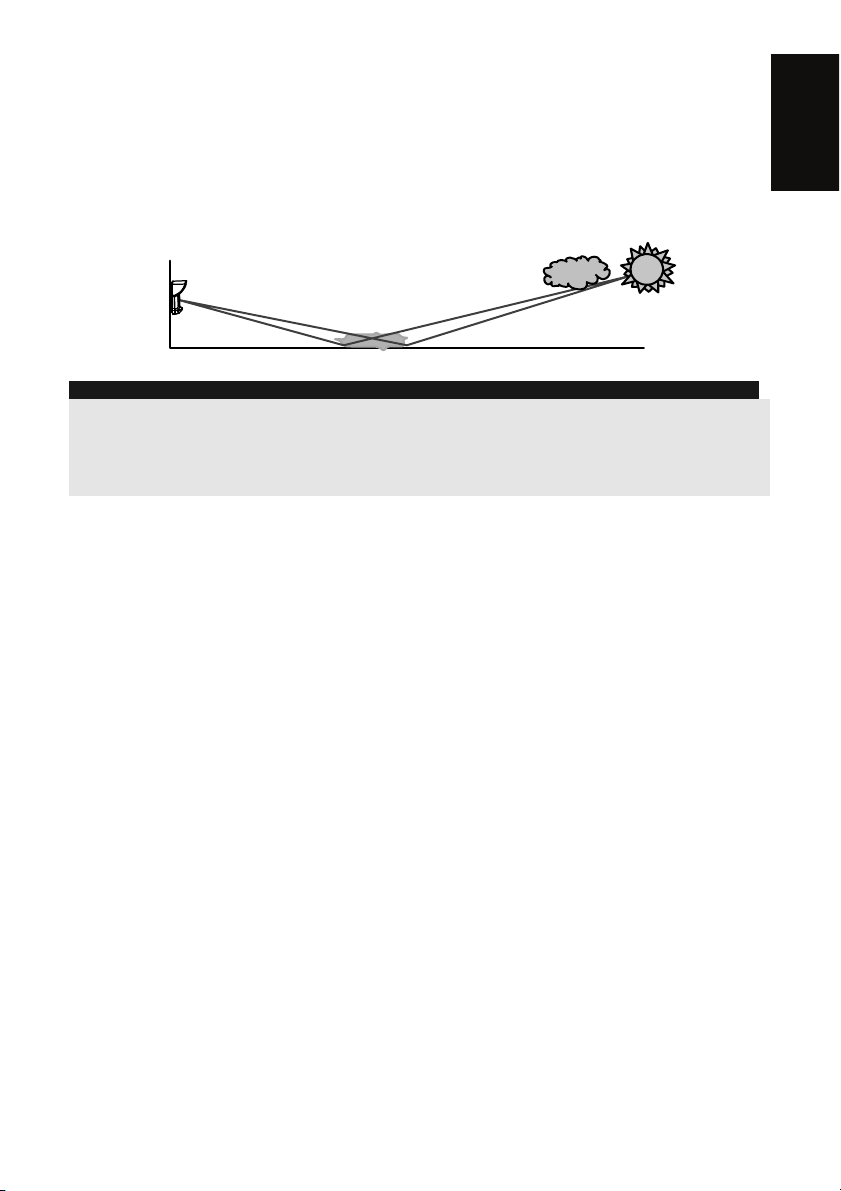
2. Situations in which a reflective surface on the ground larger than 1m (3’4”) in diameter may
cause reflection into the detector’s lens. Examples of a reflective surface on the ground are a
puddle, wet road or car park, smooth concrete or asphalt surface, swimming pool, etc.
Water Reflection
NOTES:
1. Please note that any outdoor PIR detector will require reduction in range to a shorter distance than the car,
metal object or surface reflection (so that these objects won’t be protected) in order to eliminate false alarms.
2. For full 15m (50’) coverage in the above situations, it is highly recommended to install the wired WatchOUT
DT, the only outdoor detector with 2 PIR channels and 2 Microwave channels.
3. Wireless WatchOUT detectors include high quality Silicon filters on the PIR sensors for blocking out white
light interferences. These filters are not intended to block infrared thermal radiation.
English
Installation Manual 5
Page 6
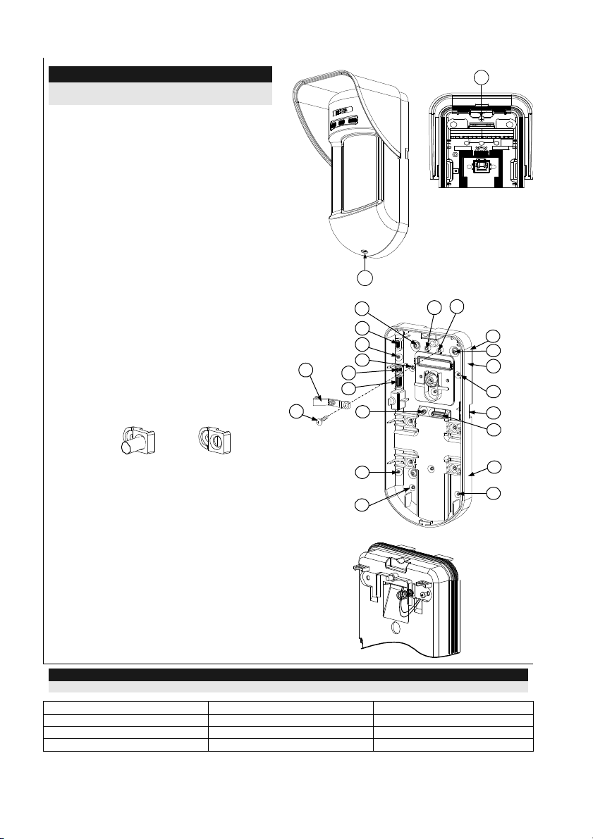
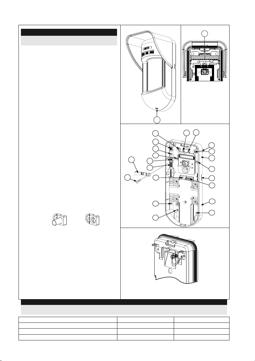
Wall Mount Installation
NOTE:
The installation knockouts numbering are marked
on the back plate.
1. Open the WL T312 front cover (unlock
C1, Figure 1).
2. Release internal base (unlock I1, Figure
2).
3. Select mounting installation as follows:
Flat Mounting:
Open knockouts on external base (Figure
3).
• B1 - B4: Wall mounting knockouts
• T1: Back tamper knockout
45° angle Mounting (Left side
mounting):
a. Open knockouts on external base
(Figure 3).
• L1, L2: Left mounting knockouts
• T3: Left tamper knockout
b. Remove tamper spring (Figure 4).
c. Replace tamper bracket (Item 1) with
supplied flat tamper bracket (Item 2).
Item 1
Item 2
Figure 1
Figure 3
Tamper
Lever
B
A
W5
W6
W3
Figure 2
C1
T1
T3
L1
B1
T6
I1
T5
T4
T2
R1
(not visible)
B2
W9
W2
d. Insert Tamper lever B onto T6 and T3
L2
and secure screw A (Figure 3).
4. Secure external base to the wall.
B4
5. Insert tamper wires through internal base
(Figure 4).
Figure 4
6. Secure internal base to external base
(lock I1, Figure 2).
7. Close the front cover (Lock C1, Figure 1)
after wiring and setting DIP switches.
8. Walk test the detector.
NOTE:
For 45° right side installation use the equivalent units on the external base as follows:
Knockouts Description Left Right
Mounting Knockouts L1, L2 R1, R2
Tamper spring knockouts T1,T3 T2,T4
Tamper screw anchor T5 T6
6 Installation Manual
R2
(not visible)
B3
Page 7
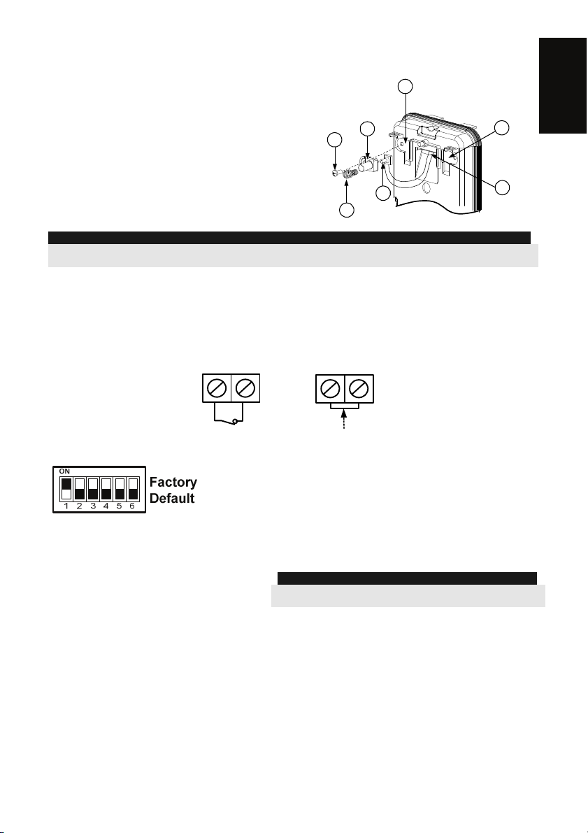
Changing Back Tamper position:
The back tamper is by default secured on the right
side of the internal base (Rear view). If you wish to
move it to the left side (rear view), do the following
(Figure 5):
1. Remove tamper screw 1 in order to release the
tamper from position 7.
2. Ensure tamper spring (2) rests over tamper wire
Figure 5
1
3
Left Side
Tamper
6
Right Side
Tamper
7
base 4.
3. Ensure plastic tamper bracket (3) rests over
both 2 and 4.
4. Secure tamper screw (1) into (3) over position 6.
4
2
5
NOTES:
1. Verify that you hear a "Click" when attaching the tamper spring to the wall.
2. For pole installation, the tamper can be moved to the bottom right-hand side of the internal base.
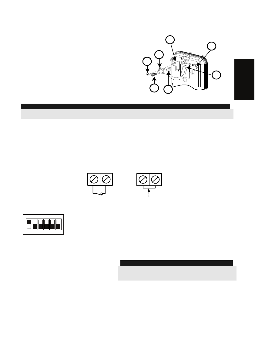
Back Tamper Terminal Wiring
If you wish to use the back tamper (recommended) remove the short from the back tamper
terminal block and connect the back tamper wires to the back tamper terminal block.
BACK TAMPER
Back Tamper in use
H1 H1
Back Tamper not used
English
Short
DIP Switch Settings
DIP 4: Not used
DIP 1: LED operation
On: LED enabled
Off: LED disabled
DIP 2: PIR detection sensitivity
On: High
Off: Normal
DIP 3: Normal/Test modes
On: Test
Off: Normal
Installation Manual 7
DIP 5: Not used
DIP 6: RF power
On: Low
Off: High
NOTE:
The DIP Switch needs to be positioned to OFF (High Power
position) unless sold in countries with FCC compliance.
Page 8
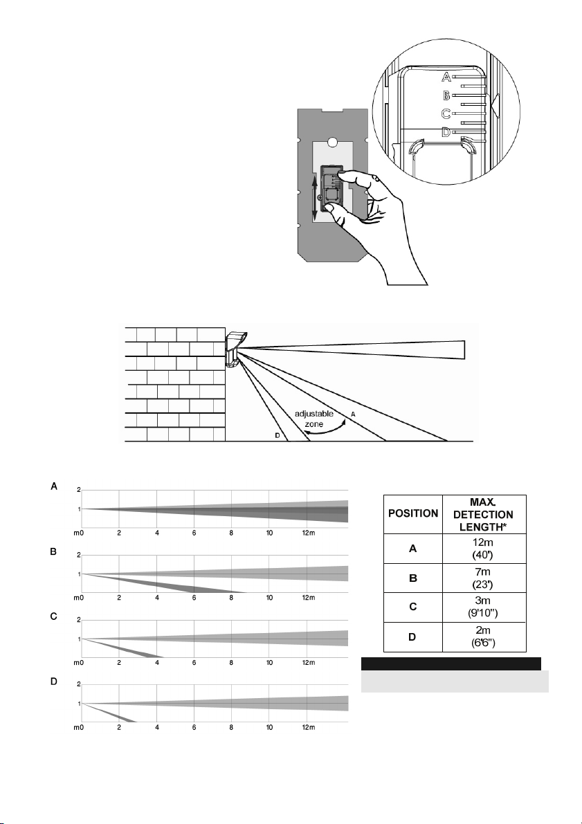
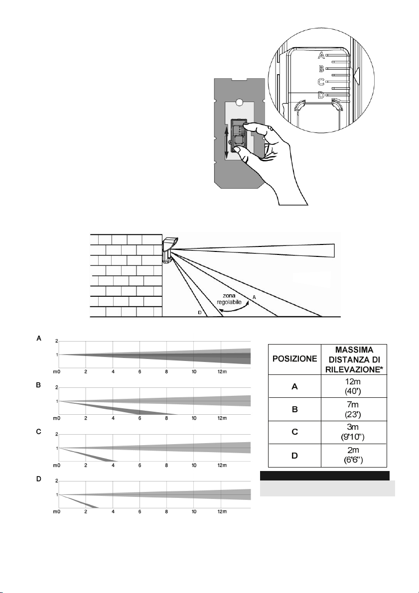
Detection Range Adjustment
Slide the moving PIR to the desired
position, see figure 6.
The range of the lower detection area
determines the detection range.
The upper PIR is fixed and its detection
area is parallel to the ground at all times.
The lower detection area changes from
2m to 12m depending on the location of
the moving PIR. Therefore, the detection
range is established according to the
location of the lower PIR since both the
upper and the lower PIR should be
triggered in order to activate an alarm.
Detection patterns (side view):
Figure 6
Detection range with 1m (3'3")
installation height:
8 Installation Manual
* NOTE:
Length may vary according to
environmental thermal conditions.
Page 9

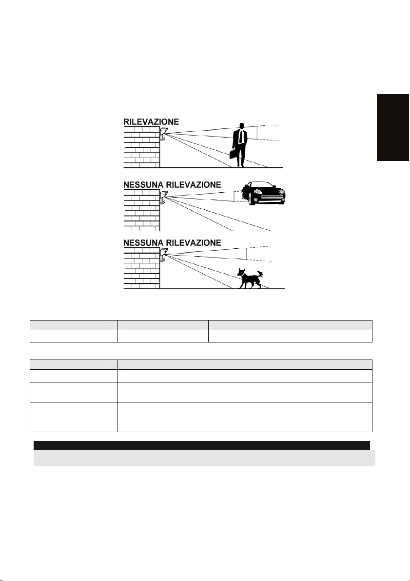
Walk test
Two minutes after applying power, walk test the protected area to verify proper operation.
Adjust the moving PIR for required detection range and reliability.
IMPORTANT!
Both upper and lower detection areas must be blocked simultaneously for detection to occur, see
figure 7 below.
English
Figure 7
LED Display
LED State Description
RED
Steady Indicates ALARM
Operational Modes
Operational Mode Description
Normal
Test (walk test)
Write (for enrolling)
NOTE:
After power up the detector enters into test mode for a period of 20 minutes (disregarding the DIP Switch Modes
Position).
Dead time (between detection alarms) is 2.5 Minutes.
Dead time (between detection alarms) is 2.5 sec.
The unit transmits a WRITE message each time both the Tamper
Switches (back and cover) are closed for at least 3 seconds.
Transmitter/Receiver Communication link setup
The detector must identify itself to the system’s receiver by writing its coded message into the
receiver’s address memory. This is accomplished by performing the following steps:
1. Set the receiver to Write Mode.
2. Remove the insulation material from the battery and place it in the battery holder on the
PCB on the right direction (pay attention to the "+" and "–" diagram on the PCB)
3. Send a WRITE message by closing both of the tamper switches (back and cover) for at
least 3 seconds.
4. Verify that the detector has been identified by the receiver.
Installation Manual 9
Page 10
CAUTION NOTICE
Changes or modifications not expressly approved by RISCO Group may void the user’s authority
to operate this equipment.
Simultaneous transmissions from two different units may cause message interference resulting in
loss of information.
The communication quality of this unit may be affected by its surrounding environment. Nearby
electrical equipment may interfere with its normal operation.
The operation of this unit must, therefore, be tested at each installation since its transmission
quality may vary as a result of operational conditions.
NOTE:
DIP Switch 1 should be in ON position to enable LED indications (regardless during the first 20 minutes after
power up).
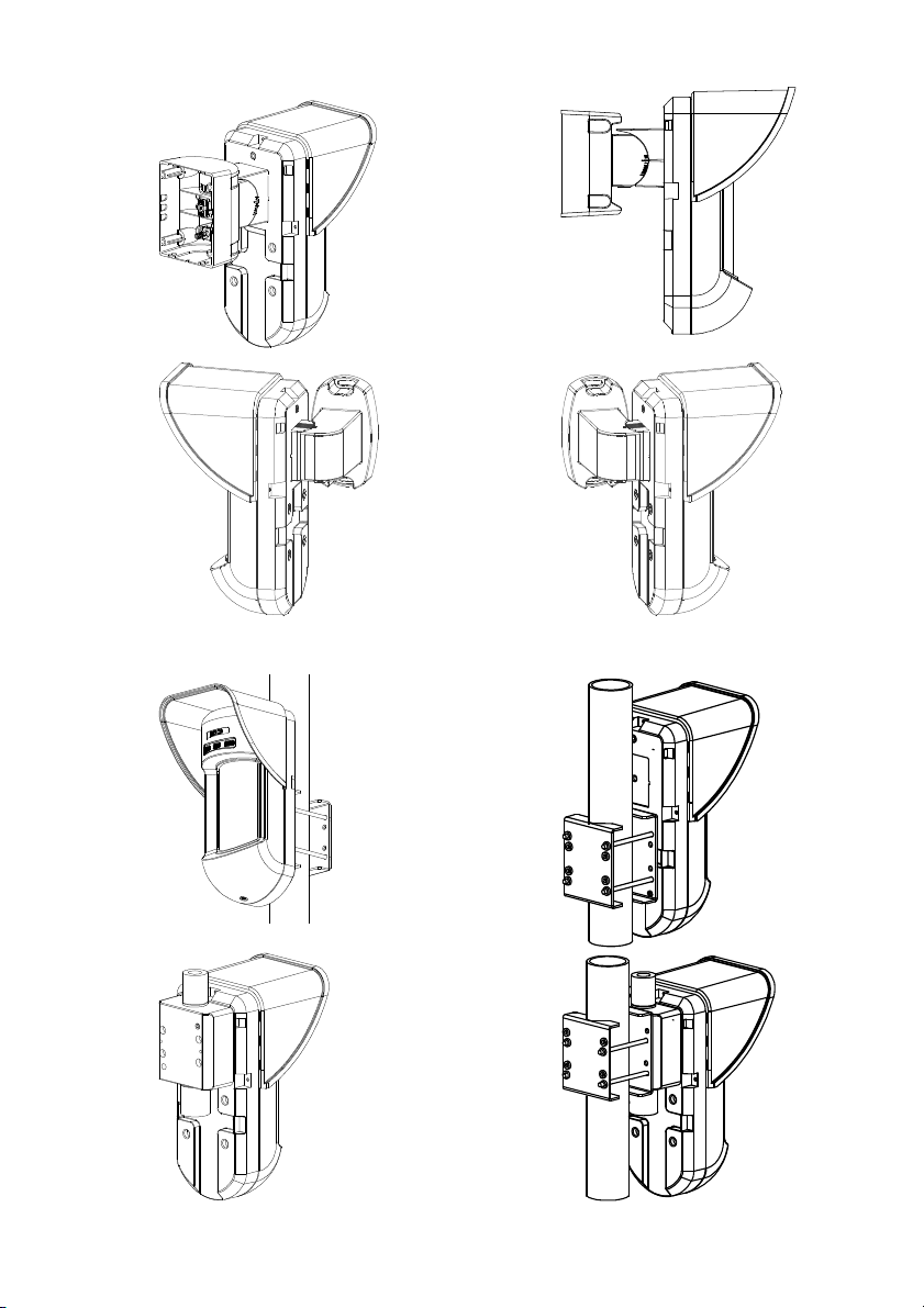
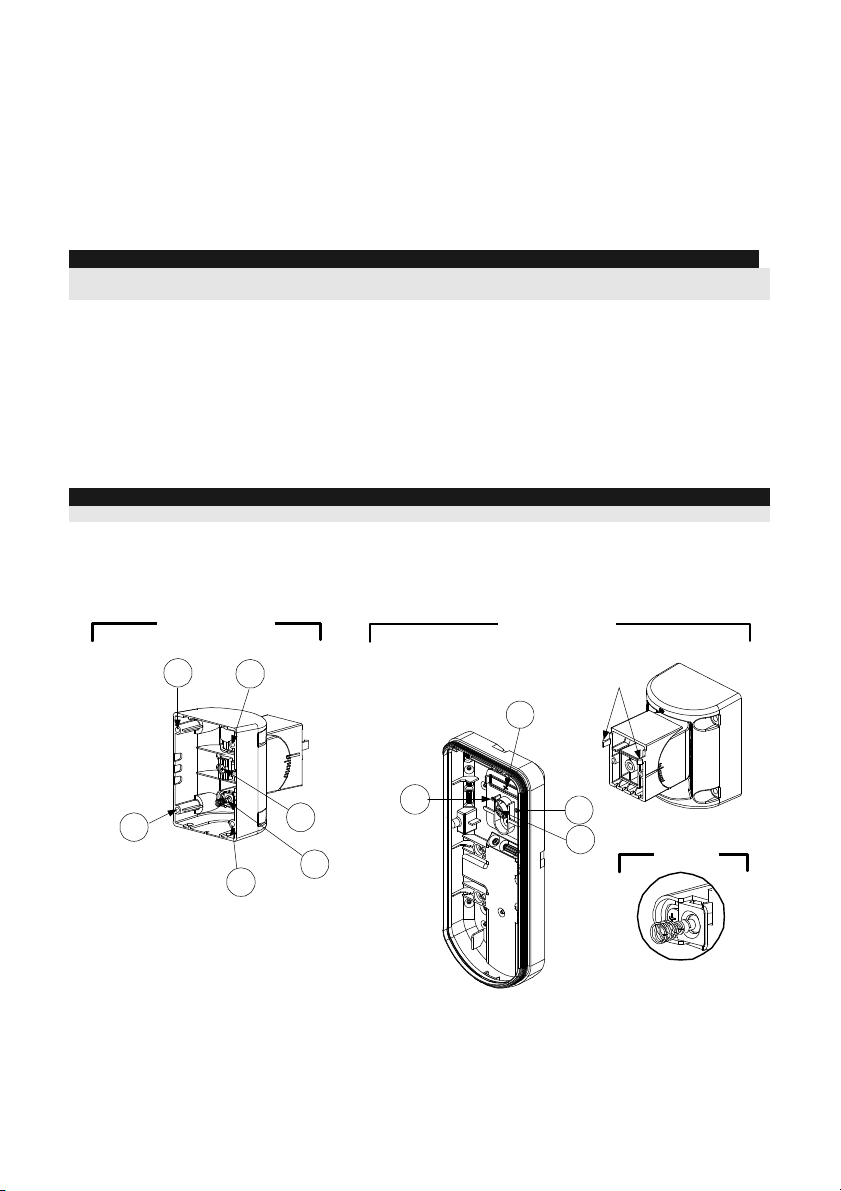
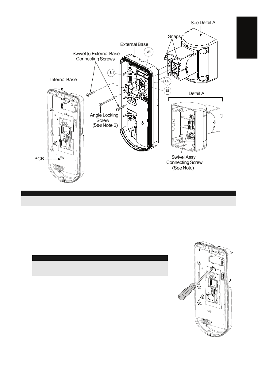
Optional Swivel Installation (Not Supplied)
Please follow the instructions below for mounting the detector with the Swivel:
1. Open WL T312 front cover (Unlock C1, Figure 1).
2. Release internal base (Unlock I1, Figure 2).
3. Remove back tamper from the internal base (see the “Changing Back Tamper Position"
paragraph on page 7) and connect it to S5 (Figure 8, Detail A) on the Standard Swivel.
4. Select the mounting installation as follows:
NOTE:
Ensure that you see the engraved UP mark on the upper front face of the swivel.
Wall Mounting
1. Insert back tamper wires through the Swivel Wires Passage (Figure 8, Detail B).
2. Secure swivel to the wall through holes S1, S3, S6 and S8.
Detail A
Standard Swivel
S1
S2
Detail B
Snaps
W1
S1
Figure 8
S6
(see Detail C)
S4
S5
Tamper
S8
3. Connect the external base to the swivel using the dedicated snaps (Figure 9).
10 Installation Manual
S2
S3
Detail C
Page 11
English
NOTE:
Figure 9
Do not open or close the Swivel Assy Screw since it is used for connecting the swivel parts only (factory
tightened).
4.
Secure external base to swivel with two screws fastened trough knockouts S1 and S2
(Figure 9).
5. Insert the supplied angle locking screw from the external base through the angle locking
screw knockout S3 on the external base to the standard swivel (Figure 9).
6. Rotate the Standard Swivel to the desired position. Once the
Standard Swivel is in the desired position, secure the angle
locking screw.
IMPORTANT!
Take care not to tilt the detector upwards and downwards. The
detector should remain perpendicular to the ground for maximum
detection and reliability.
Line up the internal base onto the external base. Insert tamper
7.
wiring through the internal base.
8. Secure internal base to external base (Lock I1, Figure 2).
9. To readjust the Standard Swivel when the PCB is installed
(Figure 10):
a. Bend down the black foam located below the RED LED on
the PCB (enough to reach the Swivel locking screw).
b. Use a Hex screwdriver to release the locking screw (see
Figure 10).
c. Rotate the Swivel to the desired position.
d. Secure the angle locking screw.
Figure 10: PCB
Installation Manual 11
Page 12
NOTE:
When marks on the two movable parts are aligned (Figure 9), the Standard Swivel is in 0° vertical/horizontal
position. Each click from this position represents shifting of 5° in vertical/horizontal position.
Close the front cover (Lock C1, Figure 1) and walk test the detector.
10.
NOTE:
The screw has to pass through the External Base and locked to the swivel.
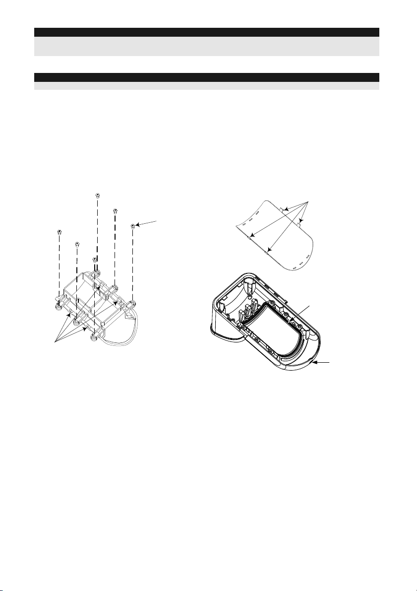
Replacing Lenses
1. Unlock the six screws that hold the lens holding sleeve from the back of the front cover.
2. To release the protective sleeve, gently push the lens from the external side of the front cover.
3. Disconnect the lens from the sleeve by gently pushing the lens clips that secure it to the
sleeve.
4. Replace the lens. Place the 4 clips of the lens into the matching holes on the sleeve.
5. Insert the protective sleeve back into place on the front cover. Pay attention to place the
sleeve over the sealing rubber.
6. Secure the 6 holding screws back to their place.
Sleeve Locking
Screws
Lens Locking
Clips
Lens Protecting
Sleeve
Sockets for
Lens Clips
.
Figure 11
12 Installation Manual
Sealing Rubber
Front Cover
Locking Screw
Page 13
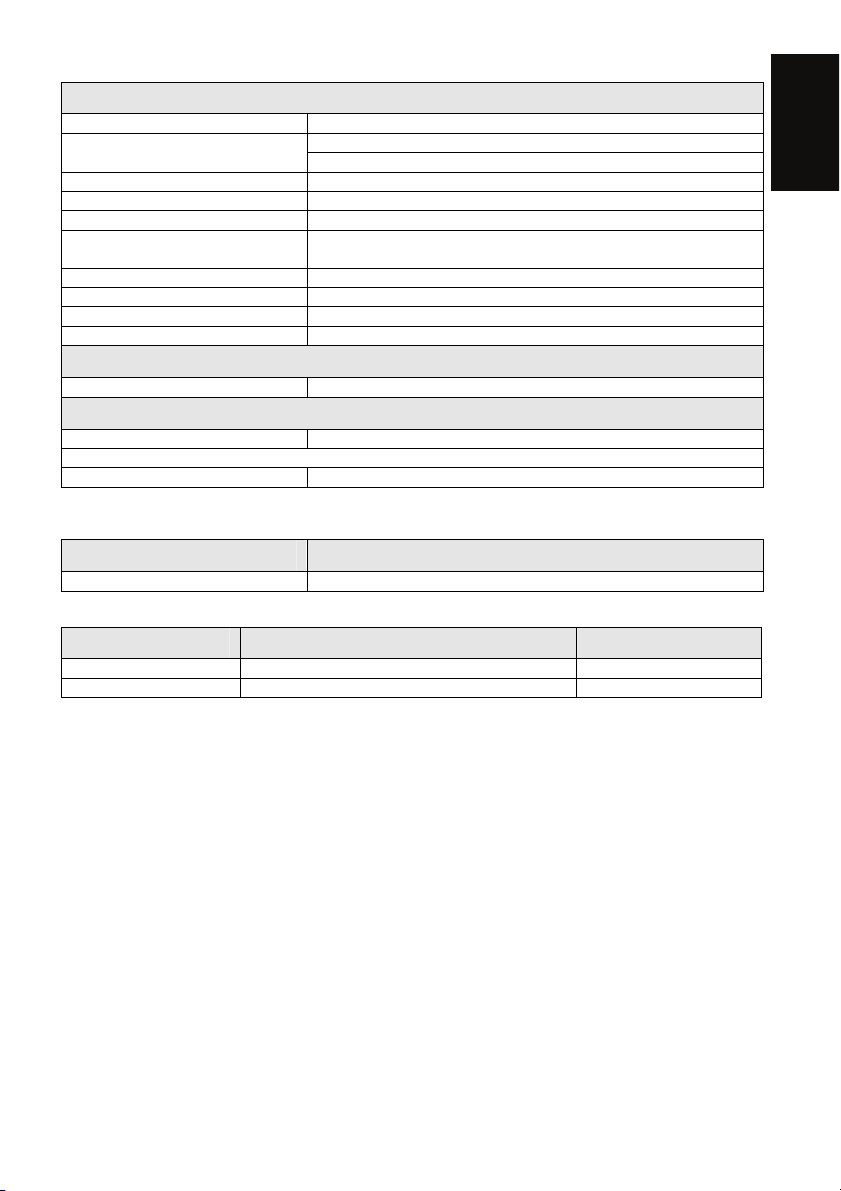
Technical Specification
Electrical
Current consumption (standby) 20uA at 3 VDC (average)
transmission)
Dead time (Normal Mode) 2.5 minutes
Modulation type ASK
Battery life 3 years (upon usage)
Supervision transmission For 868.65 MHz model: Every 15 minutes
Address codes 16 Million
Range 300m (1000 feet) Line of Sight
Battery 1 x CR123A 3VDC Lithium Battery
Frequency 433.92 / 868.65MHz
43mA at 3 VDC (Max. with LED OFF) Current consumption (Alarm
53mA at 3 VDC (Max. with LED ON)
For 433.92 MHz model: Every 65 minutes
Physical
Size (LxWxD) 230 x 121 x 123mm (9 x 4.76 x 4.85 in.)
Environmental
Operating/Storage temperature -25°C to 60°C (-13°F to 140°F)
* PIR technology is limited in harsh environmental conditions.
RF immunity According to EN50130-4
* Specifications are subject to change without prior notice.
Ordering Information
Model Description
WL T312 WatchOUT Wireless PIR 868/433
Accessory Kits
Model Description Weight
RA300S00000A Standard Swivel Kit 0.21 Kg (0.46 lb)
RA300P WatchOUT Pole Adaptor Kit 0.25 Kg (0.55 lb)
English
Installation Manual 13
Page 14

14 Installation Manual
Page 15

WL T312 - Rivelatore PIR da esterno via radio
Indice dei contenuti
Installazione..........................................................................................................................16
Introduzione..........................................................................................................................16
Installazione..........................................................................................................................16
Considerazioni preliminari..................................................................................................16
Installazione a parete.........................................................................................................18
Installazione piana .............................................................................................................18
Installazione angolare di 45° (installazione a sinistra).........................................................18
Descrizione fori a sfondare.................................................................................................18
Modifica della posizione del tamper antirimozione..............................................................19
Cablaggio del tamper antirimozione ...................................................................................19
Predisposizione Microinterruttori........................................................................................19
Regolazione area di copertura.............................................................................................20
Prova di movimento ...........................................................................................................21
Indicatore LED......................................................................................................................21
Modi operativi.......................................................................................................................21
Autoapprendimento del trasmettitore.................................................................................22
Installazione dello snodo opzionale (Non fornito)..............................................................22
Installazione a parete.........................................................................................................22
Sostituzione delle Lenti........................................................................................................24
Specifiche tecniche..............................................................................................................25
Informazioni per l’ordine......................................................................................................25
Kit accessori.........................................................................................................................25
Italiano
Istruzioni per l’installazione 15
Page 16

Installazione
Introduzione
Il rivelatore da esterno ad infrarosso passivo WatchOUT PIR Radio di RISCO Group (WLT312) è
un dispositivo a microprocessore che elabora i segnali rilevati tramite due canali all’infrarosso
passivo (PIR). Il WLT312 ha un’area di copertura regolabile. Il rivelatore è compatibile con tutti i
sistemi radio ed ibridi RISCO Group.
Le istruzioni che seguono descrivono le procedure per l’installazione del WLT312.
Installazione
Considerazioni preliminari
1. Altezza possibile: da 0.8m a 1.2m
Altezza tipica: 1m
Angolo di copertura: 90°
2. Per ottenere la migliore condizione di funzionamento ed affidabilità, installare il rivelatore
perpendicolare al terreno in modo che la zona di rilevazione superiore sia parallela al terreno.
3. Per una migliore rivelazione
selezionare una posizione
di installazione in modo che
l’eventuale intruso attraversi
l’area di copertura.
4. Evitare di direzionare l’unità verso oggetti in
movimento (alberi ondeggianti, cespugli, ecc.)
Istruzioni per l’installazione 16
5m (16')
Mantenere una distanza
di almeno 5m (16') da
oggetti in movimento
5. Assicurarsi che nessun oggetto ostruisca il
campo di rilevazione dell’unità. Prestare
attenzione alla crescita di alberi, rami e ad
eventuali altre piante che con il tempo
possono coprire l’area di rilevazione.
Fuori campo di
rilevazione
Page 17

Installazione del WL T312 in situazioni critiche:
Nelle seguenti situazioni variazioni delle radiazioni all’infrarosso rapide e rilevanti possono far si
che entrambi i canali PIR si attivino contemporaneamente, con conseguenti falsi allarmi.
1. Situazioni in cui oggetti riflettenti di vetro e/o metallo di dimensioni superiori ai 70 cm di
altezza da terra siano nel campo visivo del rivelatore (automobili, cancelli metallici,
saracinesche, muri metallici, finestre, etc.).
2. Situazioni in cui una superficie riflettente a terra con un diametro maggiore di 1m possa
causare un riflesso nelle lenti del rivelatore. Per esempio una piscina, una pozzanghera, la
strada bagnata, asfalto o cemento molto liscio.
Riflesso dell’acqua
NOTE:
1. Si noti che qualsiasi rivelatore PIR da esterno, per evitare falsi allarmi, richiede una riduzione di portata al
fine di evitare di proteggere superfici riflettenti come auto, oggetti metallici o pozzanghere.
2. Per ottenere una copertura completa nelle installazioni critiche sopra descritte, si raccomanda di
installare il WatchOUT DT cablato, l’unico rivelatore da esterno con 2 canali PIR e 2 canali a
microonde.
3. I rivelatori WatchOUT includono sui sensori PIR dei filtri al silicone di elevata qualità per filtrare le
interferenze causate dalle luci bianche. Questi filtri non bloccano le radiazioni termiche ad infrarossi
necessarie per la rilevazione degli intrusi.
Italiano
Istruzioni per l’installazione 17
Page 18
Installazione a parete
)
)
NOTA:
Figura 1
I numeri di riferimento dei fori a sfondare per
l’installazione sono marcati sulla base posteriore.
1. Aprire il coperchio frontale del WL T312
(Svitare C1, Figura 1).
2. Sganciare la base interna (svitare I1, Fig.
2).
3. Selezionare l’altezza di installazione
come segue:
Figura 2
I1
Installazione piana:
Aprire i fori a sfondare della base esterna
(Fig.3)
• B1 - B4: Fori a sfondare per
installazione a parete
• T1: Foro a sfondare per il tamper
antirimozione
Installazione angolare di 45°
(installazione a sinistra):
Figura 3
a. Aprire i fori a sfondare della base
esterna
(Figura 3)
• L1, L2: Fori a sfondare per lato
Leva del
Tamper
B
sinistro
• T3: Foro a sfondare per tamper lato
sinistro
A
b. Rimuovere la molla del tamper
c. Sostituire la staffa 1 del tamper con la
staffa piana 2 del tamper, fornita
Item 1
d. Inserire la leva B del tamper in T5 e T3
Item 2
Figura 4
e stringere la vite A (figura 3).
4. Assicurare la base esterna alla parete.
5. Inserire i cavi esterni e i cavi del tamper
attraverso la base interna (Figura 4)..
6. Assicurare la base interna a quella
esterna (bloccare I1, Figura 2).
7. Chiudere il coperchio frontale (bloccare
C1, figura 1) dopo aver predisposto i
microinterruttori.
8. Effettuare le prove di copertura.
NOTA:
Per l’installazione angolare a 45° sul lato destro del rivelatore, usare i riferimenti riportati sulla plastica della
base come da tabella seguente, colonna destra:
Descrizione fori a sfondare Sinistra Destra
Fori a sfondare per il fissaggio della base L1, L2 R1, R2
Fori a sfondare molla tamper T1,T3 T2,T4
Punto fissaggio vite Tamper T5 T6
Istruzioni per l’installazione 18
C1
T1
T3
L1
B1
W5
W6
W3
L2
B4
T5
T6
T4
T2
R1
(non visibil e
B2
W9
W2
R2
(non visibil e
B3
Page 19
Modifica della posizione del tamper
antirimozione:
Di fabbrica il tamper antirimozione è fissato sul lato
destro della base interna (vista posteriore). Se si
desidera spostarlo nella parte sinistra (vista
posteriore), procedere come segue (Figura 5):
1. Svitare la vite del tamper 1 per rimuoverlo dalla
posizione 7.
2. Assicurarsi che la molla 2 del tamper resti
posizionata sulla base 4 del tamper.
Figura 5
1
Predisposizione
tamper a sinistra
6
3
Predisposizione
tamper a destra
7
5
3. Assicurarsi che la staffa 3 del tamper resti tra 2 e 4.
4. Fissare la vite 1 del tamper in 3 sulla
predisposizione 6.
2
4
NOTE:
1. Verificare che si senta un "Click" quando la molla del tamper viene spinta verso il muro.
2. Per l’installazione su palo il tamper può essere spostato nella parte inferiore destra della base interna.
Cablaggio del tamper antirimozione
Se si desidera usare l’interruttore del tamper antirimozione (consigliato) rimuovere il cortocircuito
dai morsetti del tamper antirimozione e collegare il filo dell’interruttore antirimozione ai morsetti
dedicati al tamper antirimozione.
TAMPER ANTIRIMOZIONE
Utilizzo del tamper
antirimozione
H1 H1
Tamper antirimozione
non utilizzato
Italiano
Predisposizione Microinterruttori
ON
Default
123456
MIC. 1: Predisposizione LED
On: LED abilitati
Off: LED disabilitati
MIC. 2: Sensibilità di rilevazione PIR
On: Alta
Off: Normale
MIC. 3: Modalità Normale/Test
On: Test
Off: Normale
Cortocircuito
MIC. 4: Non usata
MIC. 5: Non usata
MIC. 6: Potenza RF
On: Bassa
Off: Alta
NOTA:
Impostare il microinterrutore 6 su ON quando il rivelatore è
vicino alla ricevente per evitare che il segnale troppo forte
saturi il ricevitore radio.
Istruzioni per l’installazione 19
Page 20
Regolazione area di copertura
Fare scorrere il PIR mobile nella
posizione desiderata, vedere figura 6.
L’impostazione dell’area di copertura del
PIR inferiore determina la portata di
rilevazione del sensore.
Il PIR superiore è fisso e la sua area di
copertura è sempre parallela al terreno.
L’area di copertura inferiore è impostabile
da 2m a 12m a seconda di dove si
posizioni il PIR regolabile. Quindi, la
portata di rilevazione del sensore è
stabilita dal posizionamento del PIR
inferiore. Per generare una condizione di
allarme sia il PIR superiore che quello
inferiore devono essere attivati.
Schema di rilevazione (vista laterale)
Figura 6
Portata di rilevazione con
installazione a 1m:
* NOTA:
La portata può variare in funzione delle
condizione climatiche esterne.
Istruzioni per l’installazione 20
Page 21
Prova di movimento
Dopo 2 minuti dall’alimentazione del sensore, effettuare una prova di movimento all’interno
dell’area protetta e verificare il buon funzionamento e la copertura del rivelatore.
Settare il PIR regolabile per ottenere la portata desiderata.
IMPORTANTE!
Entrambi canali devono essere attivati simultaneamente per generare allarme.
Vedere figura 7 sotto.
Italiano
Figura 7
Indicatore LED
LED Stato Descrizione
ROSSO
Acceso Indica ALLARME
Modi operativi
Modi operativi Descrizione
Normale
Test (prova di
movimento)
Trasmissione
indirizzo (Write) (for
enrolling)
NOTA:
All’alimentazione il rivelatore entra in modalità test per un periodo di 20 minuti senza la necessità di predisporre
su ON l’apposito microinterruttore.
Il tempo di inibizione tra due trasmissioni è di 2.5 minuti.
Il tempo di attesa tra 2 allarmi consecutivi è di 2.5 secondi.
Nella modalità di autoapprendimento l’unità trasmette un messaggio
WRITE ogni volta che gli interruttori tamper (apertura e rimozione)
vengono chiusi per almeno 3 secondi.
Istruzioni per l’installazione 21
Page 22

Autoapprendimento del trasmettitore
Il rivelatore deve essere identificato dall’unità ricevente tramite la memorizzazione del suo codice
univoco. Questa operazione viene realizzata seguendo le fasi di seguito descritte:
1. Impostare l’unità ricevente in modalità WRITE per la ricezione dell’indirizzo del rilevatore
(fare riferimento alle istruzioni fornite con l’unità ricevente).
2. Rimuovere il materiale isolante dalla batteria del rivelatore e inserirla nell’apposito alloggio
situato sulla scheda elettronica. Prestare attenzione alla polarità marcata con i simboli “+” e
“–“ sulla scheda elettronica del rivelatore.
3. Trasmettere un messaggio di indirizzo (WRITE) premendo simultaneamente per almeno 3
secondi i due interruttori tamper dell’unità (tamper apertura e rimozione).
4. Verificare che il rivelatore sia stato correttamente identificato dal ricevitore (il ricevitore
emette una segnalazione acustica e/o visualizza sul suo display il menù successivo).
AVVERTENZA
Modifiche o variazioni non approvate espressamente da RISCO Group possono fare decadere il
diritto dell’utente all’utilizzo di questa apparecchiatura.
Trasmissioni simultanee da due differenti apparati possono causare interferenze e relativa perdita
delle informazioni trasmesse.
La qualità di comunicazione di questa apparecchiatura può dipendere dall’ambiente in cui è
installata. Apparecchiature elettriche situate nelle vicinanze possono creare interferenze al
normale funzionamento dell’apparato.
Per i motivi citati il funzionamento di questa apparecchiatura deve essere testato ad ogni
installazione poiché la qualità di comunicazione può variare al variare del sito di installazione.
NOTA:
Il microinterruttore 1 deve essere posto in ON per abilitare l’indicatore LED (tranne che per i primi 20 minuti di
funzionamento dopo l’alimentazione del rivelatore).
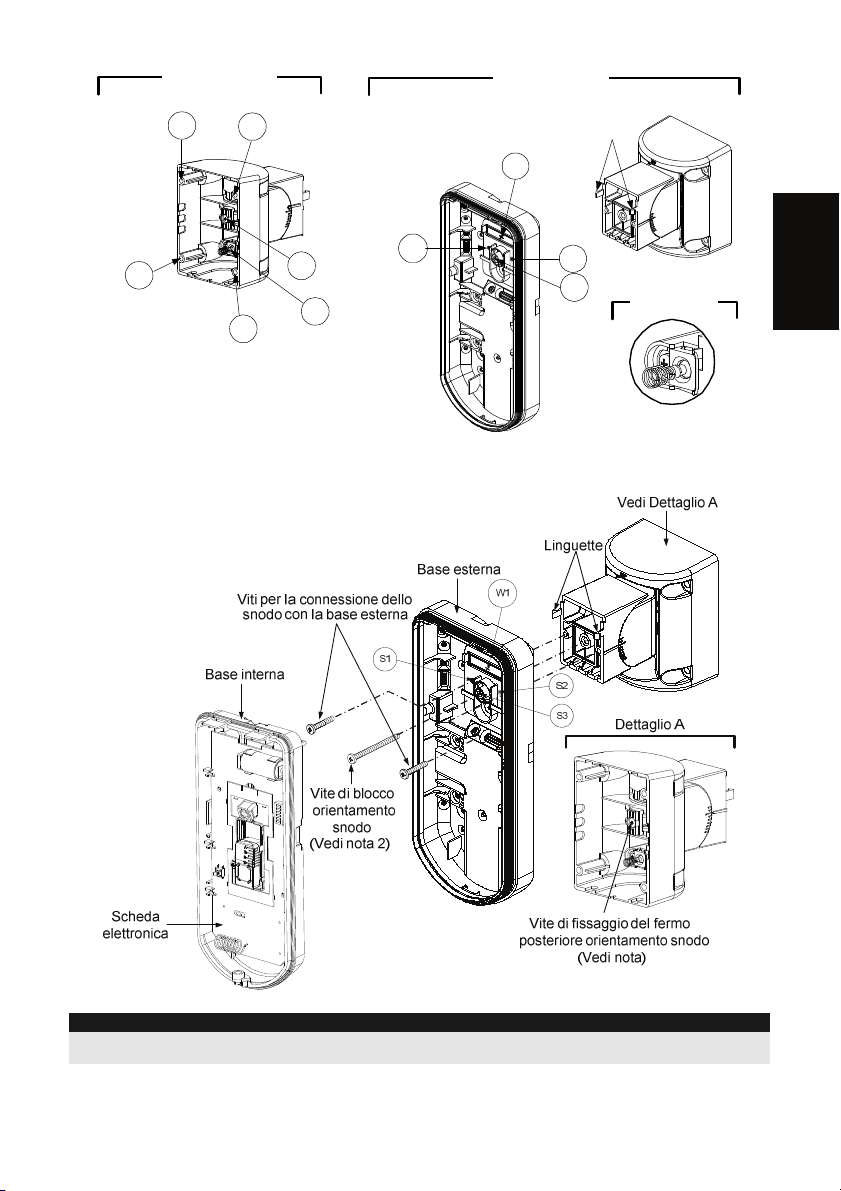
Installazione dello snodo opzionale (Non fornito)
Leggere le istruzioni seguenti per installare il rivelatore con questo snodo:
1. Aprire il coperchio frontale (Allentare C1, Figura 1).
2. Sganciare la base interna (Svitare I1, Figura 2).
3. Rimuovere il tamper antirimozione dalla base interna (consultare paragrafo "Modifica della
posizione del tamper antirimozione") e collegarlo a S5 (Figura 8, Dettaglio A) sullo snodo
standard.
4. Selezionare le opzioni di installazione di seguito descritte:
NOTA:
Accertarsi che il marchio UP è presente nella parte frontale superiore dello snodo.
Installazione a parete
1. Inserire i cavi del tamper antirimozione facendoli passare tramite il passaggio cavi dello
snodo (Figura 8, Dettaglio B).
2. Fissare lo snodo alla parete tramite i fori S1, S3, S6 ed S8.
Istruzioni per l’installazione 22
Page 23
Dettaglio A
Snodo standard
S1
S2
Dettaglio B
Linguette
W1
S8
3. Unire la base esterna allo snodo utilizzando le apposite linguette ad incastro (Figura 9).
S4
S6
S5
Tamper
( vedi dettaglio C)
S1
Figura 8
S2
S3
Dettaglio C
Italiano
NOTA:
Figura 9
Per fissare la base del rivelatore allo snodo non usare la vite che blocca il fermo posteriore dello snodo. Questa
vite non va usata poiché serve solo per il blocco dello snodo una volta orientato come desiderato.
Fissare la base esterna allo snodo con due viti tramite le predisposizioni S1 e S2 (Figura 9).
4.
5. Inserire nello snodo standard la vite (fornita) di fissaggio ad angolo facendola passare dalla
base esterna attraverso il foro a sfondare S3 (Figura 9).
Istruzioni per l’installazione 23
Page 24

Orientare lo snodo standard nella posizione desiderata. Quando
6.
viene raggiunta la posizione desiderata, stringere la vite di blocco
orientamento snodo.
IMPORTANTE!
Prestare attenzione a non disorientare lo snodo verso l’alto e verso il
basso. Il rivelatore deve rimanare perpendicolare al terreno per ottenere
la massima portata di rilevazione e affidabilità.
Infilare la base interna nella base esterna ed inserire tutti i cavi
7.
attraverso la base interna.
8. Fissare la base interna a quella esterna (fissare I1, figura 2).
9. Per regolare lo snodo standard quando viene installata la scheda
elettronica procedere come segue (Figura 10):
a. Spostare la gomma nera situata sulla scheda elettronica
sotto al LED rosso (quanto basta per raggiungere la vite di
blocco dello snodo).
b. Utilizzare un cacciavite per svitare la vite di blocco (Figura
10).
c. Orientare lo snodo nella posizione desiderata.
d. Stringere la vite di blocco orientamento snodo.
Figura 10: Scheda
elettronica
NOTA:
Quando i punti marcati delle due parti mobili sono allineati (figura 9), lo snodo standard si trova in posizione 0°.
Ogni “click” verticale da questa posizione corrisponde ad un incremento / decremento di 5°.
Chiudere il coperchio frontale (fissare C1, figura 1) e proseguire con la prova di movimento
10.
per verificare l’area di copertura del rivelatore.
NOTA:
La vite deve passare attraverso la base esterna ed essere fissata allo snodo.
Sostituzione delle Lenti
1. Nella parte interna del coperchio frontale svitare le sei viti che mantengono il supporto
lenti.
2. Per sganciare il supporto delle Lenti effettuare una leggera pressione sulle lenti dalla
parte anteriore del coperchio.
3. Sganciare le Lenti dal supporto facendo leggermente leva sulle clip laterali delle Lenti.
4. Sostituire le Lenti. Inserire le 4 clip delle Lenti negli appositi fori del supporto.
5. Inserire il supporto delle Lenti nel coperchio frontale del rivelatore. Prestare particolare
attenzione a riposizionare il supporto esattamente sopra la guarnizione di gomma,
verificando che anche la lente utilizzata per la protezione verticale dell’unità abbia la
guarnizione correttamente posizionata.
6. Fissare il supporto tramite le 6 viti.
Clip di
blocco Lenti
Viti di fissaggio
supporto
Fori per clip
di blocco
Lenti
Supporto Lenti
Figura 11
Istruzioni per l’installazione 24
Guarnizione
Vite di
fissaggio
coperchio
frontale
Page 25

Specifiche tecniche
Elettriche
Assorbimento in corrente (a riposo) 20uA a 3 Vcc (assorbimento medio)
(trasmissione allarme)
Inibizione trasmissioni (Modo
normale di funzionamento)
Tipo di modulazione ASK
Autonomia batteria 3 anni (da quando viene utilizzata)
Trasmissione di supervisione Per modelli 868.65 MHz: Ogni 15 minuti
Codici di indirizzo 16 milioni
Portata in aria libera 300m
Batteria Batteria al litio 1 x CR123A 3VDC
Frequenza 433.92 / 868.65MHz
43mA a 3 Vcc (max. con LED spento) Assorbimento in corrente
53mA a 3 Vcc (max. con LED acceso)
2.5 minuti
Per modelli 433.92 MHz: Ogni 65 minuti
Fisiche
Dimensioni (LxWxD) 230 x 121 x 123mm
Ambientali
Temp. operativa/stoccaggio Da -25°C a 60°C
* La tecnologia di rilevazione PIR è limitata in condizioni ambientali critiche.
Immunità interferenze RF Conforme alla normativa EN50130-4
* Le specifiche tecniche sono soggette a variazioni senza l’obbligo di preavviso.
Informazioni per l’ordine
Modello Descrizione
WL T312 WatchOUT PIR radio 868/433
Italiano
Kit accessori
Modello Descrizione Peso
RA300S Kit snodo standard 0.21 Kg
RA300P Kit adattatore da palo 0.25 Kg
Istruzioni per l’installazione 25
Page 26

Istruzioni per l’installazione 26
Page 27

WL T312 Detector de Exterior PIR Inalámbrico
Índice de Contenidos
Instalación ............................................................................................................................28
Introducción .........................................................................................................................28
Montaje .................................................................................................................................28
Consideraciones de Montaje..............................................................................................28
Instalación en Pared .......................................................................................................... 30
Montaje Plano:...................................................................................................................30
Montaje en ángulo de 45° (montaje del lado izquierdo):.....................................................30
Descripción........................................................................................................................30
Cambiando la posición del Tamper Posterior.....................................................................31
Cableado del Terminal del Tamper Posterior ..................................................................... 31
Configuración de los Interruptores DIP..............................................................................31
Ajuste del Alcance de Detección.........................................................................................32
Prueba de Movimiento .........................................................................................................33
Indicación del LED ...............................................................................................................33
Modos de Funcionamiento .................................................................................................. 33
Establecer la Comunicación entre el Transmisor y el Receptor .......................................34
Opcional: Instalación de la Rótula Estándar (No suministrada)........................................34
Montaje en Pared...............................................................................................................34
Cambio de la Lente...............................................................................................................36
Especificaciones Técnicas..................................................................................................37
Información para Pedidos....................................................................................................37
Kits de Accesorios...............................................................................................................37
Español
Instrucciones de Instalación 27
Page 28

Instalación
Introducción
El WL T312 de RISCO Group es un detector con procesamiento de señal basado en dos canales
de Infrarrojo Pasivo (PIR). El WL T312 posee un rango de detección ajustable. El detector es
compatible con los sistemas Híbridos e Inalámbricos de RISCO Group.
Las siguientes instrucciones describen la instalación del detector WL T312.
Montaje
Consideraciones de Montaje
1. Altura de Instalación: 0,8 m – 1,2 m
(2'8'' – 3'11'')
Altura Normal de Instalación: 1 m (3'3'')
2. Para garantizar la máxima fiabilidad en su funcionamiento, instalar el detector perpendicular
al suelo, de manera que el área de detección superior quede paralelo al suelo.
3. Para una detección óptima,
seleccione una localización
en la que sea probable
interceptar un intruso
moviéndose a través del
patrón de cobertura.
4. Evite apuntar el detector hacia objetos
que se muevan (árboles meciéndose,
arbustos, etc.)
Instrucciones de Instalación 28
5m(16')
Mantenga una distancia mínima
de 5 metros (16”)
de objetos que se muevan
5. Asegúrese que ningún objeto obstruya el
campo de visión. Preste atención a árboles o
arbustos en crecimiento, plantas con hojas
grandes que se puedan mover con el viento,
etc.
Fuera del Área de
Detección
Page 29

Instalando el WL T312 en situaciones comprometidas:
En las siguientes situaciones pueden producirse cambios rápidos y significativos de la radiación
infrarroja en ambos canales PIR simultáneamente, dando lugar a falsas alarmas. Por lo tanto hay que
tener un especial cuidado con ellas:
1. Situaciones en las que haya objetos metálicos y/o de cristal de más de 70 cm (2'4") de altura
respecto al suelo, y que estén en el campo de visión del detector (coches, puertas metálicas,
persianas, paredes de metal, ventanas, etc.)
2. Situaciones en las cuales una superficie brillante en el suelo de más de 1 m (3'4") de diámetro
pueda provocar reflejos en la lente del detector. Ejemplos de superficies reflectantes en el suelo
son los charcos, una carretera o aparcamiento mojado, una superficie lisa de cemento o asfalto,
una piscina, etc
.
Reflejo del Agua
NOTAS:
1. Por favor, tenga presente que cualquier detector PIR de exterior necesitará reducir su alcance a una
distancia más corta de dicho coche, objeto metálico o superficie reflectante (por lo que estos objetos no se
protegerán), a fin de eliminar las falsas alarmas.
2. En las situaciones anteriores, para tener una completa cobertura de 15 m (50') se recomienda instalar el
detector WatchOUT DT cableado, el único detector de exterior con 2 canales PIR y 2 canales Microondas.
3. Los detectores WatchOUT Inalámbricos incluyen filtros de silicio de alta calidad en los sensores PIR para
bloquear las interferencias de luz blanca. Estos filtros no están diseñados para bloquear la radiación
térmica infrarroja.
Español
Instrucciones de Instalación 29
Page 30

Instalación en Pared
NOTA:
La numeración de cada agujero pre-marcado está
indicada en la base posterior.
1. Abrir la tapa delantera del WL T312
(desatornillar C1, Figura
1).
2. Sacar la base interna (desatornillar I1,
Figura 2).
3. Seleccionar el tipo de montaje:
Figura 1
Figura 2
I1
Montaje Plano:
Abrir los siguientes agujeros pre-marcados
en la base externa
• B1 - B4: Agujeros pre-marcados
para la instalación en pared.
• T1: Agujero pre-marcado para el
tamper posterior.
Montaje en ángulo de 45° (montaje
del lado izquierdo):
a. Abrir los siguientes agujeros pre-
marcados en la base externa
• L1, L2: Agujeros pre-marcados
para montaje del lado izquierdo.
• T3: Agujero pre-marcado para el
tamper en el lado izquierdo.
b. Quitar el muelle del tamper (Fig. 4).
c. Reemplazar la abrazadera del tamper
(Ítem 1) con la abrazadera plana del
tamper suministrada (Ítem 2)
d. Insertar la palanca B del tamper en el
T6 y T3 y fijarla con el tornillo A (Fig. 3)
4. Fijar la base externa a la pared.
5. Pasar los cables del tamper a través de
la base interna (Figura 4).
6. Asegurar la base interna a la base
externa (atornillar I1, Figura 2).
7. Cerrar la tapa delantera (atornillar C1,
Figura 1) después de cablear y
configurar los interruptores DIP.
8. Hacer una prueba de detección del
detector.
NOTA:
Para la instalación del lado derecho a 45°, usar las unidades equivalentes en la base externa como sigue:
Descripción Lado Izquierdo Lado Derecho
Agujeros pre-marcados de montaje L1, L2 R1, R2
Agujeros pre-marcados del muelle del
tamper
Tornillo de sujeción del tamper
(Figura 3).
Ítem 1
C1
Figura 3
T1
(Fig. 3)
Palanca del
Tamper
B
A
Ítem 2
Figura 4
T3
L1
B1
W5
W6
W3
L2
B4
T5
T6
T4
T2
R1
(no visible)
B2
W9
W2
R2
(no visible)
B3
T1,T3 T2,T4
T5 T6
Instrucciones de Instalación 30
Page 31

Cambiando la posición del Tamper
Posterior
Por defecto el tamper posterior se asegura
en el lado derecho de la base interna (vista
posterior). Si desea moverlo al lado
izquierdo (vista posterior), haga lo siguiente
(Figura 5):
1. Quite el tornillo 1 del tamper para liberar
Figura 5
1
Tamper del Lado
Izquierdo
6
3
Tamper del Lado
Derecho
7
el tamper de la posición 7.
2. Asegúrese que el muelle del tamper (2)
está asentado sobre la base con los
cables del tamper (4).
3. Asegúrese que la abrazadera plástica
del tamper (3) esté asentada en el 2 y 4.
4. Fije el tornillo del tamper (1) en (3) sobre
la posición 6.
4
2
5
NOTAS:
1. Asegúrese que escucha un "clic" al fijar el muelle del tamper a la pared.
2. Para instalación en poste, el tamper puede moverse a la parte inferior del lado derecho de la base interna.
Cableado del Terminal del Tamper Posterior
Si desea utilizar el tamper posterior (recomendado), quite el cortocircuito del bloque de terminales
del tamper posterior y conecte los cables del tamper posterior a los bornes del tamper posterior.
BACK TAMPER
Back Tamper in use
H1 H1
Back Tamper not used
Español
Configuración de los Interruptores DIP
DIP 4: Lente RL 303*
DIP 1: Funcionamiento del LED
ON: LED activado
OFF: LED desactivado
DIP 2: Sensibilidad de detección del PIR
ON: Alta
OFF: Normal
DIP 3: Modo Normal/Test
ON: Test
OFF: Normal
DIP 5: Anti-inclinación*
DIP 6: Potencia RF
NOTA:
El interruptor DIP 6 debe ponerse en la posición OFF
(Potencia Alta), a menos que se venda en países que deban
cumplir con las normas FCC.
* No disponible en todos los mercados y modelos.
Instrucciones de Instalación 31
Short
ON: Utilizada
OFF: No utilizada
ON: Anti-inclinación activado
OFF: Anti-inclinación desactivado
ON: Baja
OFF: Alta
Page 32

Ajuste del Alcance de
Detección
Deslizar el PIR móvil hasta la posición
deseada (ver figura 6).
El alcance de la zona de detección
inferior determina la distancia de
detección del detector.
El PIR superior es fijo, y su zona de
detección es siempre paralela al suelo. La
zona de detección inferior varía de 2 a 12
metros, dependiendo de la posición del
PIR móvil. Por lo tanto, el área de
detección del detector viene fijado por la
posición del PIR inferior, puesto que para
generar una alarma deben dispararse los
dos PIR (tanto el superior como el
inferior).
Figura 6
Patrones de detección (vista lateral):
Alcance de detección con una altura
de instalación de 1m (3'3"):
* NOTA:
La distancia puede variar en función de
las condiciones de temperatura ambiente.
Instrucciones de Instalación 32
Page 33

Prueba de Movimiento
Dos minutos después de dar alimentación al detector, hacer la prueba de movimiento en el área
protegida para verificar su correcto funcionamiento.
Ajustar el PIR móvil para la distancia de detección y fiabilidad requeridas.
¡IMPORTANTE!
Ambas zonas de detección, superior e inferior, deben bloquearse de forma simultánea para que
se produzca una detección (ver Figura 7).
Español
Figura 7
Indicación del LED
LED Estado Descripción
ROJO
Fijo Indica ALARMA
Modos de Funcionamiento
Modo de
Funcionamiento
Normal
Test (prueba de
movimiento)
Escritura
(para darlo de alta)
Nota:
Al dar alimentación al detector, éste entra en el modo Test durante un período de 20 minutos (sin importar el
Modo de funcionamiento definido con la posición del DIP 3).
Descripción
El tiempo muerto (entre dos alarmas de detección) es de 2,5 minutos.
El tiempo muerto (entre dos alarmas consecutivas) es de 2,5 segundos.
La unidad transmite un mensaje de ESCRITURA cada vez que los dos
tampers (posterior y tapa) se cierran durante al menos 3 segundos.
Instrucciones de Instalación 33
Page 34

Establecer la Comunicación entre el Transmisor y el Receptor
El detector debe identificarse en el receptor del sistema, escribiendo su código en la dirección de
memoria del receptor. Para ello hay que realizar los siguientes pasos:
1. Poner el receptor en Modo Escritura.
2. Quitar el material aislante de la pila y colocarla en el soporte para la pila que hay en la
placa de circuito impreso (prestar atención a la polaridad, marcada con "+" y "–" en la
PCB).
3. Enviar un mensaje de ESCRITURA, presionando los dos tampers (posterior y tapa)
durante al menos 3 segundos.
4. Verificar que el detector ha sido identificado por el receptor.
ADVERTENCIA
Cambios o modificaciones no aprobados expresamente por RISCO Group podrían anular el
derecho del usuario a utilizar este equipo.
Las transmisiones simultáneas desde dos unidades distintas pueden provocar interferencias,
dando lugar a una pérdida de información.
La calidad de la comunicación de esta unidad puede verse afectada por el entorno que le rodea.
Aparatos eléctricos cercanos al detector podrían interferir en su funcionamiento normal.
Por lo tanto, debe comprobarse el funcionamiento de esta unidad en cada instalación, puesto que
su calidad de transmisión puede variar como resultado de las condiciones de cada instalación.
Nota:
El interruptor DIP 1 debe estar en la posición ON para habilitar el indicador LED (independientemente de que el
detector esté en los primeros 20 minutos después de darle alimentación).
Opcional: Instalación de la Rótula Estándar (No suministrada)
Por favor, siga las siguientes instrucciones para montar el detector con la Rótula:
1. Abrir la tapa frontal del WL T312. (Desatornillar C1, Figura 1).
2. Desenganchar la base interna (Desatornillar I1, Figura 2).
3. Desmontar el tamper posterior de la base interna (ver apartado “Cambiando la Posición del
Tamper Posterior") y colocarlo en la Rótula Estándar en S5 (Figura 8, Detalle A).
4. Seleccionar la opción de instalación como se indica a continuación:
Nota:
Asegurarse que la marca UP grabada en el frontal de la rótula está en la parte de arriba.
Montaje en Pared
1. Insertar los cables del tamper posterior a través del conducto para los cables de la Rótula
(Figura 8, Detalle B).
2. Fijar la rótula a la pared mediante los agujeros S1, S3, S6 y S8 (Figura 8, Detalle A).
Instrucciones de Instalación 34
Page 35

B
Detalle
A
Rótula Estándar
S1
S2
Detalle
Clips a
presión
W1
S8
S6
(ver Detalle C)
S4
S1
S5
Tamper
S2
S3
Figura 8
3.
Unir la base externa a la rótula usando los clips a presión de sujeción (Figura 9).
Detalle C
Español
Nota:
Figura 9
No aflojar ni apretar el Tornillo de Ensamblaje de la Rótula (Figura 9, Detalle A) ya que se utiliza únicamente
para unir las piezas de la rótula (viene atornillado de fábrica).
4.
Fijar la base externa a la rótula con 2 tornillos sujetos a través de los agujeros pre-marcados
S1 y S2 (Figura 9).
5. Insertar el tornillo suministrado para la fijación del ángulo, haciéndolo pasar a través del
agujero pre-marcado S3 en la base externa hasta unirlo con la rótula estándar
(Figura 9).
Instrucciones de Instalación 35
Page 36

6. Girar la Rótula Estándar hasta la posición deseada. Una vez que
la rótula estándar está en la posición que buscamos, apretar el
tornillo de fijación del ángulo.
¡IMPORTANTE!
Tenga cuidado de no inclinar el detector hacia arriba o hacia abajo. El
detector debería permanecer perpendicular al suelo para lograr la máxima
detección y fiabilidad.
Alinear la base interna con la base externa. Insertar el cableado
7.
del tamper a través de la base interna.
8. Fijar la base interna a la externa (Atornillar I1, Figura 2).
9. Para reajustar la posición de la Rótula Estándar una vez que la
PCB ya está instalada (Figura 10):
a. Levantar la espuma negra situada debajo del LED ROJO en
la PCB (lo suficiente para poder acceder al tornillo de fijación
del ángulo de la rótula).
b. Usar un destornillador de estrella para aflojar el tornillo de
fijación (ver Figura 10).
c. Girar la Rótula hasta la posición deseada.
Figura 10: PCB
d. Apretar el tornillo de fijación del ángulo.
Nota:
Cuando las marcas de las dos partes móviles de la rótula están alineadas (Figura 9), la Rótula Estándar está
en la posición 0°. Cada “clic” vertical desde esta posición representa un incremento o decremento de 5°.
Cerrar la tapa delantera (Atornillar C1, Figura 1) y hacer la prueba de movimiento del
10.
detector.
Nota:
El tornillo de fijación del ángulo tiene que pasar a través de la Base Externa y fijarse a la rótula.
Cambio de la Lente
1. Desatornillar los seis tornillos que sostienen la funda protectora de la lente de la parte posterior
de la tapa delantera.
2. Para extraer la funda protectora, empujar suavemente la lente desde el lado externo de la tapa
delantera.
3. Separar la lente de la funda empujando suavemente los clips de fijación que la sujetan a la
funda.
4. Sustituir la lente. Colocar los 4 clips de la lente en los agujeros apropiados en la funda.
5. Volver a insertar la funda protectora en su lugar en la tapa delantera. Prestar atención al
colocar la funda sobre la goma de sellado.
6. Atornillar los 6 tornillos colocados de nuevo en su lugar.
Tornillos de
fijación de la
Funda
Clips de Fijación
de la Lente
Agujeros para los
clips de la lente
Funda Protectora de la
Lente
Figura 11
Instrucciones de Instalación 36
Goma de
sellado
Tapa Delantera
Tornillo de
Fijación de la
Page 37

Especificaciones Técnicas
Eléctrica
Consumo de corriente (reposo) 20 µA a 3 Vcc (media)
(transmisión de alarma)
Tiempo muerto (Modo Normal) 2,5 minutos
Tipo de modulación ASK
Duración de la batería 3 años (en función del uso)
Transmisión de Supervisión Para el modelo 868,65 MHz: Cada 15 minutos
Códigos de dirección 16 Millones
Rango (pérdida) 300 m (1000 pies) en campo abierto
Batería 1 pila de Litio CR123A 3 Vcc
Frecuencia 433,92 / 868,65 MHz
43 mA a 3 Vcc (Máx. con el LED apagado) Consumo de corriente
53 mA a 3 Vcc (Máx. con el LED encendido)
Para el modelo 433,995 MHz: Cada 65 minutos
Física
Tamaño (LxAxP) 230 x 121 x 123 mm (9 x 4.76 x 4.85 pul.)
Ambiental
Temperatura de Funcionamiento
/ Almacenamiento
* La tecnología PIR se ve limitada en condiciones ambientales severas.
Inmunidad a RF Según EN 50130-4
* Las especificaciones están sujetas a cambios sin previo aviso.
-25°C a 60°C (-13°F a 140°F)
Información para Pedidos
Modelo Descripción
WL T312 WatchOUT PIR Inalámbrico 868/433
Español
Kits de Accesorios
Modelo Descripción Peso
RA300S Kit de Rótula Estándar 0,21 Kg (0.46 lb)
RA300P Kit Adaptador de Poste para WatchOUT 0,25 Kg (0.55 lb)
Instrucciones de Instalación 37
Page 38

Instrucciones de Instalación 38
Page 39

WL T312 - Détecteur PIR extérieur sans fil
Table des Matières
Installation............................................................................................................................40
Introduction..........................................................................................................................40
Montage ................................................................................................................................ 40
Conditions de montage ......................................................................................................40
Installation murale.............................................................................................................. 42
Montage à plat ..................................................................................................................42
Montage à 45° (montage sur côté gauche) ........................................................................42
Désignation des pastilles pré-percées................................................................................ 42
Changement de position de l'autoprotection arrière...........................................................43
Câblage du terminal de l'autoprotection .............................................................................43
Réglage de la zone de détection..........................................................................................44
Test de passage ................................................................................................................45
Afficheur à diodes LED........................................................................................................45
Modes opérationnels............................................................................................................45
Paramétrage de la liaison Transmetteur/ Récepteur..........................................................45
Installation de l'accessoire support orientable, optionel (non fourni)..............................46
Installation murale.............................................................................................................. 46
Remplacement des lentilles.................................................................................................48
Spécifications techniques ................................................................................................... 49
Information Catalogue .........................................................................................................49
Kit accessoroires .................................................................................................................49
Français
Manuel d'installation
39
Page 40

Installation
Introduction
Le WL T312 de RISCO Group est un détecteur unique qui utilise l’analyse de signal de deux
canaux de détection à infrarouge passif (PIR). Le WL T312 est pourvu d’une zone de détection
ajustable. Le détecteur est compatible avec tous les systèmes sans fil et hybrides de RISCO
Group.
Les instructions suivantes vous décrivent comment intaller le WL T312.
Montage
Conditions de montage
1. Hauteur optionnelle : 0.8m - 1.2m
Hauteur caractéristique: 1m
2. Afin d’assurer une efficassité maximum de fonctionnement, installer le détecteur
perpendiculairement par rapport au sol afin que la zone supérieure de détection soit parallèle
au sol.
3. Pour obtenir une capacité
maximale de détection,
choisissez un endroit
susceptible de capter le
passage de tout intrus dans
la zone couverte.
4. Évitez d'orienter le détecteur vers des
objets en mouvement (buissons, arbres
aux branches oscillantes etc.)
Manuel d'installation 40
Maintenez une distance
de 5 m au moins entre
le détecteur et tout objet
5. Assurez-vous qu'aucun objet n'obstrue le
champ de vision. Prêtez attention aux
buissons ou arbres en pleine croissance, aux
plantes aux grandes feuilles souples, etc.
5m(16')
Hors de portée de
détection
Page 41

Installation du détecteur WL T312 dans des conditions particulières:
Dans les situations suivantes, des modifications importantes et rapides de radiation infrarouge
peuvent se produire dans les deux canaux PIR à la fois, risquant d'entraîner de fausses alarmes,
d'où la nécessité de prendre certaines précautions :
1. Si des objets de métal et/ ou en verre atteignant plus de 70cm (2’4”) de hauteur au-dessus du
sol se trouvent dans le champ de vision du détecteur (véhicules, portails métalliques, volets,
parois métalliques, fenêtres, etc.),
2. Si une surface réfléchissante au sol supérieure à 1m (3’4”) de diamètre est susceptible de
provoquer une réflexion dans la lentille du détecteur. Par exemple : une flaque d'eau, une
chaussée humide ou une aire de stationnement, une surface en béton poli ou d'asphalte, une
piscine, etc.
Réflexion sur l'eau
REMARQUES :
1. Veuillez prendre note que tout détecteur PIR extérieur nécessite une réduction de portée à plus courte
distance que l'endroit où se trouve la voiture, l'objet métallique ou la surface de réflexion (de sorte que
ces objets ne sont pas protégés), et ce, afin de neutraliser les fausses alarmes.
2. Pour une couverture complète de 15m (50’) dans les conditions décrites ci-dessus, il est vivement
recommandé d'installer un détecteur WatchOUT DT, seul détecteur extérieur doté de 2 canaux PIR et
de 2 canaux Micro-ondes.
3. Les détecteurs ‘WatchOUT' sans fil sont équipés de filtres en Silicium de haute qualité placés sur les
capteurs PIR pour bloquer les interférences causées par la lumière blanche. Ces filtres ne sont pas
conçus pour le blocage des radiations thermales infrarouges.
Français
Manuel d'installation 41
Page 42

Installation murale
REMARQUE :
Pour faciliter l'installation, les pastilles défonçables
prévues à cet effet sont numérotées sur la paroi
arrière de l'appareil.
1. Ouvrez le couvercle du WL T312.
(Débloquez en
C1, Figure 1).
2. Dégagez le socle interne (débloquez en
I1, Figure 2).
3. Choisissez le mode d'installation comme
:
suit
Figure 1
Figure 2
I1
Montage à plat :
Percez les pastilles pré-percées du socle
externe (Figure 3).
• B1 - B4: pastilles pré-percées pour
installation murale.
• T1: pastille pré-percées de
l'autoprotection arrière
Figure 3
Montage à 45° (montage sur côté
gauche) :
a. Percez les pastilles pré-percées du
socle externe (Figure 3)
• L1, L2: pastilles pré-percées pour
montage à gauche.
• T3: pastille pré-percées de
l'autoprotection arrière.
b. Retirez le ressort de l'autoprotection
(Figure 4).
c. Remplacez le crochet d'autoprotection
(pièce 1) par le crochet d'autoprotection
plat fourni (pièce 2).
Pièce 1
d. Insérez le doigt d'autoprotection B aux
Pièce 2
endroits marqués T6 et T3, ensuite
serrez la vis A
(Figure 3)
4. Fixez le socle externe de l'appareil au mur.
5. Faites passer les câbles d'autoprotection
dans le socle interne (Figure 4).
6. Fixez le socle interne au socle externe
(bloquez en I1, Figure 2).
7. Fermez le couvercle (bloquez en C1,
Figure 1) après avoir installé les fils
électriques et placé les interrupteurs DIP.
8. Effectuez un test de passage avec le
détecteur.
REMARQUE :
Pour une installation à 45° sur côté droit, utilisez les pièces équivalentes du socle externe comme suit :
Désignation des pastilles pré-percées Côté gauche Côté droit
Pastilles pré-percées pour montage
Pastilles pré-percées du ressort de l'autoprotection
Cheville pour les vis de l'autoprotection
Manuel d'installation 42
Manette
d'autoprotection
B
A
Figure 4
C1
T5
T1
T3
L1
B1
W5
W6
W3
L2
B4
T6
L1, L2 R1, R2
T1,T3 T2,T4
T5 T6
T4
T2
R1
invisible
B2
W9
W2
R2
invisible
B3
Page 43

Changement de position de
l'autoprotection arrière
L'autoprotection arrière est, par défaut, fixée sur le
côté droit du socle interne (vue arrière). Si vous
souhaitez la déplacer sur le côté gauche (vue
arrière), procédez comme suit (Figure 5):
1. Retirez la vis d'autoprotection 1 pour dégager
Figure 5
Autoprotection gauche
3
1
6
Autoprotection droite
7
l'autoprotection de la position 7.
2. Assurez-vous que le ressort de l'autoprotection
2 repose bien sur la base de câblage 4.
3. Vérifiez que le crochet en plastique 3 de
l'autoprotection repose bien sur les points 2 et
4.
4
2
5
4. Serrez la vis d'autoprotection 1 dans la pièce 3
en la faisant passer par la position 6.
REMARQUES :
1. Veillez à entendre un "Clic" en fixant le ressort de l'autoprotection au mur.
2. Pour l'installation sur un mât, l'autoprotection peut être déplacée vers le côté inférieur droit du socle interne.
Câblage du terminal de l'autoprotection
Si vous souhaitez utiliser l'autoprotection arrière (comme recommandé), retirez le court—circuit de
son bloc de connexion et branchez le câble du terminal de l'autoprotection au bloc de connexion.
Auto protection arrière
Autoprotection utilisée
H1 H1
Autoprotection non utilisée
Français
Réglage des interrupteurs DIP
DIP 1: Fonctionnement des diodes LED
Marche (ON) : diodes LED activées.
Arrêt (OFF) : diodes LED désactivées
DIP 2: Sensibilité de détection PIR
Marche (ON) : Elevé
Arrêt (OFF) : Normal
DIP 3: Mode Normal/ Mode Test
Marche (ON) : Test
Arrêt (OFF) : Normal
Court-circuit
DIP 4: Non utilisée
DIP 5: Non utilisée
Manuel d'installation 43
DIP 6: Puissance RF
Marche (ON) : Basse
Arrêt (OFF) : Elevée
REMARQUE :
L’interrupteur DIP à besoin d’être positionnée sur OFF
(puissance élevée à moins que les contacts ne soient soudés
pour la pays qui suivent la conformité FCC.
Page 44

Réglage de la zone de détection
Faite glisser l’élément PIR adjustable jusqu’à
la position désirée, voir figure 6.
La zone de détection basse détermine la
distance de détection.
L’élement PIR supérieur est fixe et sa zone
de détection est paralèle au sol en
permanence. La zone de détection basse est
réglable de 2m à 12m en function du réglage
de l’élément PIR. Par conséquent la zone de
détection est établie selon la position de
l’élément PIR inférieur, étant donné que les
deux éléments PIR inférieur et supérieur
doivent être sollicités afin de déclencher
l’alarme.
Zones de détection (vue latérale):
Figure 6
Distance de détection pour une
installation du détecteur à 1m de
hauteur :
* REMARQUE :
La longueur pourrait variée selon les
conditions termiques environnementales.
Manuel d'installation 44
Page 45

Test de passage
Deux minutes après la mise sous tension, effectuez un test de passage dans la zone protégée
afin de vérifier le bon fonctionnement de l'installation.
Ajuster l’élement PIR mobile afin d’obtenir une détection appropriée et une bonne fiabilité.
IMPORTANT!
Les deux zones de détection supérieure et inférieure doivent être sollicitées en même temps pour
qu’une détection soit réalisée. Voir figure 7 ci-dessous.
Français
Figure 7
Afficheur à diodes LED
LED Etat Description
ROUGE
Continu Indique une ALARME
Modes opérationnels
Mode opérationnel Descrizione
Normal
Test (de passage)
Ecriture (par
enrôlement)
REMARQUE :
Après sa mise sous tension, le détecteur se met en mode de test pendant 20 minutes (quelle que soit la position
des interrupteurs DIP).
Temps mort (entre alarmes de détection) : 2 minutes 30.
Temps mort (entre alarmes) : 2 secondes 30.
L'appareil transmet un message de programmation chaque fois que les
deux interrupteurs d'autoprotection (arrière et couvercle) se ferment
pendant au moins 3 secondes.
Paramétrage de la liaison Transmetteur/ Récepteur :
Le détecteur doit s'identifier auprès du récepteur du système par la mémorisation de son
message codé dans le registre d'adresses de ce dernier. Pour ce faire, veuillez procéder comme
suit :
1. Réglez le récepteur en Mode Ecriture.
2. Retirez l’emballage des piles et installez-les dans le logement prévu à cet effet sur la carte
PCB vers la droite (en respectant les polarités "+" et "–" qui figure sur la carte PCB)
3. Envoyez un message de programmation en appuyant simultanément sur les deux
interrupteurs d'autoprotection (arrière et couvercle) pendant au moins 3 secondes.
4. Vérifiez ensuite que le détecteur a bien été identifié par le récepteur.
Manuel d'installation 45
Page 46

ATTENTION !
Tous changements ou modifications apportés à ce matériel sans l'approbation expresse du
Groupe RISCO pourrait invalider l'autorisation donnée à l'utilisateur de le faire fonctionner.
Des transmissions simultanées en provenance de différents appareils pourraient provoquer des
interférences dans les messages, entraînant ainsi une perte de l'information.
La qualité de la communication assurée par cet appareil peut être affectée par son
environnement. La présence d'autres appareils électriques à proximité pourrait en perturber le
bon fonctionnement.
Celui-ci doit par conséquent être testé à chaque installation étant donné que la qualité de
transmission de l'appareil dépend des conditions auxquelles il est soumis.
REMARQUE :
Pour permettre les indications LED, l'interrupteur DIP 1 doit se trouver en position ON (sans tenir compte des 20
premières minutes suivant la mise sous tension).
Installation de l'accessoire support orientable, optionel (non fourni)
Pour intégrer ce dernier à l'installation du détecteur, veuillez suivre les instructions ci-dessous:
1. Ouvrez le couvercle du WatchOUT (débloquez en C1, Figure 1).
2. Dégagez le socle interne (débloquez en I1, Figure 2).
3. Retirez l'autoprotection arrière du socle interne (cf. § “Changement de position de
l'autoprotection arrière") et reliez-la au point S5 (Figure 8, Détail A) sur le support standard.
4. Choisissez le mode de montage comme suit :
REMARQUE :
Assurez-vous de voir la marque UP gravée sur la face supérieure du support.
Installation murale
1. Introduisez les fils électriques de l'autoprotection arrière à dans le passage du support prévu
à cet effet (Figure8, Détail B).
2. Fixez le support orientable au mur en passant par les entrées S1, S3, S6 et S8.
Détail A
Support standard
S1
S2
Détail B
Pattes
W1
S8
S6
Autoprotection
(cf. Détail C)
S4
S1
S5
Figure 8
S2
S3
Détail C
3. Fixez le socle externe au support orientable à l'aide des pressions prévues (Figure 9).
Manuel d'installation 46
Page 47

Vis de fixation socle
externe sur le support
Socle externe
W1
Pressions
Cf.
Détail A
en angle
S1
S2
S3
Vis de fixation de
l’ensemble pivot
Détail A
(cf. Remarque)
Socle interne
Vis de fixation
(cf. Remarque 2)
PCB
Figure 9
REMARQUE :
Ne pas serrez ou desserrez la vis de connexion dusupport car elle sert seulement à assembler les pièces du
support orientable (serrage seulement en usine).
4. Fixez le socle externe au pivot à l'aide de deux vis passant par les pastilles pré-percées S1
et S2 (Figure 9).
5. Introduisez la vis de fixation d'angle fournie en partant du socle externe et en passant par la
pastille pré-percée S3 de la vis de fixation d'angle située sur le socle externe, pour atteindre
le support standard (Figure 9).
6. Incliner le support standard jusqu’à la position désirée. Dès que
la position désirée est obtenue, bloquer la position en serrant les
vis de blocage d’angle.
IMPORTANT!
Prenez soin de ne pas incliner le détecteur vers l’avant ni vers l’arrière. Le
détecteur devrait rester idéalement perpendiculaire par rapport au sol
pour offrir la détection maximum et la meilleure fiabilité.
7. Alignez le socle interne avec le socle externe. Insérez les fils
électriques de l'autoprotection par le socle interne.
8. Fixez le socle interne au socle externe (bloquez en I1, Figure 2).
9. Pour rajuster le pivot standard lorsque la carte PCB est installée
(Figure 10):
a. Abaissez la mousse noire qui se trouve en dessous de la
diode ROUGE sur la carte PCB (suffisamment pour
atteindre la vis de fixation du support orientable).
b. A l'aide d'un tournevis hexagonal, desserrez la vis de
fixation (cf. Figure 10).
c. Incliner le support jusqu’à la position désirée.
d. Serrez la vis de fixation d'angle.
Figure 10: PCB
Manuel d'installation 47
Français
Page 48

REMARQUE :
Lorsque les marques indiquées sur les pièces mobiles sont bien alignées (Figure 7), le support standard se
trouve à 0° en position verticale/ horizontale. Chaque cran à partir de cette position correspond à une
inclinaison de 5° dans la position verticale / horizontale.
10. Refermez le couvercle (bloquez en C1, figure 1) et effectuez un test de passage avec le
détecteur.
REMARQUE :
La vis doit traverser le socle externe pour finalement se fixer au pivot.
Remplacement des lentilles
1. Desserrez les six vis qui fixent la gaine de maintien de la lentille à l'envers du couvercle.
2. Pour enlever cette gaine de protection, poussez délicatement la lentille depuis l'extérieur du
couvercle.
3. Séparez la lentille de la gaine en poussant délicatement les crochets qui la retiennent à
celle-ci.
4. Remplacez la lentille. Placez les 4 languettes de fixation de la lentille dans les trous
correspondants de la gaine.
5. Réinsérez la gaine de protection à sa place sur le couvercle. Veillez à ce qu'elle couvre le
joint en caoutchouc.
6. Replacez et resserrez les 6 vis de fixation.
Vis de fixation de
la gaine
Languettes de fixation
de la lentil le
Trous destinés à recevoir les
languettes de fixation de la
lentille
Gaine de protection de
la lentille
Manuel d'installation 48
Figure 11
Joint en
caoutchouc
Vis de fixation du
couvercle
Page 49

Spécifications techniques
Caractéristiques électriques
Consommation électrique (en veille) 20uA à 3 VCC (en moyenne)
transmission d'alarme)
Temps mort (mode normal) 2 minutes 30
Type de modulation ASK
Durée de vie des piles 3 ans (dépendant de l’utilisation)
Transmission de supervision Pour le modèle 868.65 MHz : Toutes les 15 minutes
Codes d'adresses 16 Millions
Portée (perte) 300m ligne directe
Pile 1 x CR123A 3VDC pile au Lithium
Fréquence 868,65MHz
43mA à 3 VCC (max. avec diodes LED éteintes) Consommation électrique (en
53mA à 3 VCC (max. avec diodes LED allumées)
Caractéristiques physiques
Dimensions (L x l x P) 230 x 121 x 123mm
Caractéristiques environnementales
Température de fonctionnement/
stockage
* La technologie IRP est limitée dans des conditions environnementales difficiles.
Immunité RF Répond à la norme EN50130-4
* Ces spécifications sont susceptibles d'être modifiées sans avis préalable.
De -25°C à 60°C
Information Catalogue
Modèle Description
WL T312 WatchOUT sans fil PIR 868
Kit accessoroires
Modèlo Description Poids
RA300S Set rotule standard 0,21 Kg
RA300P Set adaptateur pour mât WatchOUT 0,25 Kg
Français
Manuel d'installation 49
Page 50

Manuel d'installation 50
Page 51

WL T312 - Detector Infravermelho Passivo
Externo Sem Fio
Índice
Instalação..............................................................................................................................52
Introdução.............................................................................................................................52
Montagem.............................................................................................................................52
Considerações de Montagem.............................................................................................52
Instalação de Montagem em Parede..................................................................................54
Montagem Plana................................................................................................................54
Montagem em ângulo de 45° (montagem do lado esquerdo) .............................................54
Trocando a posição do tamper Traseiro............................................................................. 55
Fiação do Terminal do Tamper traseiro..............................................................................55
Configuração do Interruptor Dip .........................................................................................55
Ajuste de faixa de detecção.................................................................................................56
Teste de Caminhada..........................................................................................................57
Visualização dos LED ..........................................................................................................57
Modos Operacionais ............................................................................................................ 57
Configuração da Conexão de Comunicação do Transmissor/Receptor...........................58
Instalação do Suporte Rotativo Opcional (Não incluso)....................................................58
Montagem em Parede........................................................................................................58
Trocando as Lentes..............................................................................................................60
Especificações Técnicas .....................................................................................................61
Informação para Pedidos.....................................................................................................61
Kits de acessórios................................................................................................................61
Português
Instruções para Instalação 51
Page 52

Instalação
Introdução
O WL T312 da RISCO Group, é um detector exclusivo com processamento de sinais baseado em
dois canais de infravermelho passivo (IVP). O WL T312 tem um alcance de detecção ajustável. O
detector é compatível com todos os paineis híbridos e sem fio da RISCO Group.
Montagem
Considerações de Montagem
1. Altura Opcional: 0.8m - 1.2m (2'8" – 3'11'')
Altura Típica: 1m (3'3")
2. Para garantir a máxima confiabilidade operacional, instale o detector perpendicular ao chão,
para que os segmentos de detecção superior sejam paralelos ao solo.
3. Para uma melhor detecção,
selecione uma localização
que seja provável para
interceptar um intruso
movendo-se através do
padrão de cobertura.
4. Evite dirigir o campo de visão do detector a
objetos que se movem (árvores que
balançam arbustos etc.)
Mantenha uma distância de
no mínimo 5 metros (16”)
de objetos móveis
5m(16')
5. Certifique-se que nenhum objeto obstrui o
campo de detecção. Preste atenção às
árvores ou aos arbustos em crescimento,
às plantas com folhas grandes que se
movem etc.
Fora da Área de
Detecção
Instruções para Instalação 52
Page 53

Instalando o WL T312 em situações desafiantes
Nas seguintes situações, as mudanças rápidas e significativas da radiação infravermelha podem
acontecer em ambos os canais PIR simultaneamente, resultando em falsos alarmes, então deve se
tomar cuidado em:
1. Situações nas quais objetos de metal e/ou de vidro que têm mais de 70 cm (2'4") de altura desde o
solo se encontram no campo de visão do detector (carros, portas de metal, persianas, paredes de
metal, janelas, etc.)
2. Situações nas quais uma superfície refletiva no solo com mais de 1m (3'4") de diâmetro pode
causar reflexos na lente do detector. Exemplos de uma superfície refletiva no solo são uma poça,
um caminho ou estacionamento de carros molhado, uma superfície lisa de concreto ou de asfalto,
uma piscina, etc
.
Reflexo da Água
NOTAS:
1. Observe por favor, que qualquer detector Infravermelho Passivo externo requerer redução no alcance a
uma distância mais curta que um carro, um objeto de metal ou um reflexo da superfície (de modo que
estes objetos não sejam protegidos) para eliminar falsos alarmes.
2. Para uma cobertura completa de 15m (50') nas situações mencionadas anteriormente, recomenda-se
instalar o WatchOUT DT, o único detector externo com 2 canais de Infravermelho Passivo e 2 canais de
microondas.
3. Os detectores WatchOUT Sem fio incluem filtros de silicone de alta qualidade nos sensores de
Infravermelho Passivo, para bloquear interferências leves brancas. Estes filtros não são projetados para
bloquear radiação térmica infravermelha.
Português
Instruções para Instalação 53
Page 54

Instalação de Montagem em Parede
NOTA:
A numeração dos furos pré-marcados para a
instalação está marcada na placa traseira.
1. Abra a tampa dianteira do WL T312.
(abra C1, Figura
1).
2. Libere a base interna (abra I1, Figura 2).
3. Selecione a instalação de montagem
como segue:
Figura 1
Figura 2
I1
Montagem Plana:
Abra os furos pré-marcados na base
externa
(Figura 3).
• B1 - B4: Furos pré-marcados para
montagem em parede
• T1: Furo pré-marcado do tamper
posterior
Montagem em ângulo de 45°
Figura 3
(montagem do lado esquerdo):
a. Abra os furos pré-marcados na base
externa
• L1, L2: Furos pré-marcados para
(Figura 3)
montagem do lado esquerdo
• T3: Furo pré-marcado do tamper
esquerdo
b. Remova a mola do tamper (Figura 4).
c. Substitua a braçadeira do tamper
(Item 1) pela braçadeira plana do
tamper (fornecida) (Item 2).
Item 1
d. Insira a alavanca B do tamper no T6
e T3 e aperte o parafuso A (figura 3)
4. Fixe a base externa à parede.
5. Insira os cabos do tamper através da
base interna (Figura 4).
6. Fixe a base interna à base externa
(Feche I1, Figura 2).
7. Feche a tampa dianteira (Feche C1,
Figura 1) depois de conectar a fiação e
configurar os interruptores Dip.
8. Faça o teste de caminhada no detector.
NOTA:
Para instalação do lado direito a 45° use as unidades equivalentes na base externa como segue:
Descrição Lado Esquerdo Lado Direito
Furos pré-marcados de montagem
Furos pré-marcados da mola do tamper
Bucha do parafuso do tamper
Item 2
Alavanca do
Tamper
B
A
Figura 4
C1
T1
T3
L1
B1
W5
W6
W3
L2
B4
T5
T6
(não visível)
(não visível )
L1, L2 R1, R2
T1,T3 T2,T4
T5 T6
T4
T2
R1
B2
W9
W2
R2
B3
Instruções para Instalação 54
Page 55

Trocando a posição do tamper Traseiro
o
O tamper traseiro está fixado (Configuração de
fábrica) no lado direito da base interna (vista
traseira). Se você deseja passá-lo para o lado
esquerdo (vista traseira), faça o seguinte
(Figura 5):
1. Retire o parafuso 1 do tamper para liberar o
tamper da posição 7.
Figura 5
Tamper do Lado Esquerdo
3
1
6
Tamper do Lado Direit
7
2. Certifique-se que a mola (2) do tamper está
assentada sobre a base do cabo do tamper
4.
3. Certifique-se que a braçadeira plástica do
tamper (3) está assentada no 2 e 4.
4. Assegure o parafuso do tamper (1) no (3)
sobre a posição 6.
4
2
5
NOTAS:
1. Certifique-se de escutar um "clique" ao fixar a mola do tamper à parede
2. Para instalação em poste, o tamper pode ser passado para a parte inferior do lado direito da base interna.
Fiação do Terminal do Tamper traseiro
Se desejar utilizar o tamper traseiro (recomendado) retire o curto-circuito do terminal de fiação do
tamper e conecte o cabo do tamper traseiro ao terminal do tamper traseiro.
TAMPER TRASEIRO
Tamper Traseiro em uso
H1 H1
Tamper Traseiro não usado
Configuração do Interruptor Dip
DIP 1: Operação dos LEDs
On: LEDs ativados
Off: LEDs desativados
DIP 2: Sensibilidade de Detecção de
Infravermelho Passivo
On: Alta
Off: Normal
DIP 3: Modalidades Normal/Teste
On: Teste
Off: Normal
Curto
DIP 4: Não usado
DIP 5: Não usado
DIP 6: Potência de RF
On: Baixa
Off: Alta
NOTA:
O dipswitch 6 deve estar na posição OFF, (Alta potência de
RF), a menos que sejam vedidos em países em conformidade
com a FCC.
Instruções para Instalação 55
Português
Page 56

Ajuste de faixa de detecção
Deslize o Infravermelho Passivo (IVP)
móvel para a posição desejada, veja a
figura 6.
A distância dos segmentos de detecção
inferiores determina a área protegida.
O IVP superior é fixo, e os segmentos de
detecção são paralelos sempre paralelos
ao chão.
A área de detecção externa muda de 2
metros até 12 metros, dependendo da
localização do IVP móvel. Portanto, a
faixa de detecção é estabelecida de
acordo com a localização do IVP baixo,
desde que ambos os IVP´s baixo e alto
sejam disparados ao mesmo tempo.
Padrão de detecção (Visão lateral):
Figura 6
Faixa de detecção com altura de
instalação de 1m (3'3"):
* NOTA:
As distâncias podem variar de acordo com
as condições térmicas ambientais.
Instruções para Instalação 56
Page 57

Teste de Caminhada
Dois minutos depois de ligar a energia elétrica, faça o teste de Caminhada na área protegida para
verificar a operação apropriada.
Ajuste o IVP móvel para proteger com confiabilidade a área necessária.
IMPORTANTE!
Ambas as áreas de detecção detevem disparar simultaneamente para que uma detecção ocorra,
conforme a figura 7 abaixo.
Figura 7
Visualização dos LED
LED Estado Descrição
VERMELHO
Constante Indica ALARME
Modos Operacionais
Modo Operacional Descrição
Normal
Teste (walktest)
Escrever (Para
cadastrar)
NOTA:
Depois de ativado o detector entra no modo de teste por um período de 20 minutos (não levando em conta a
Posição dos Modos do interruptor DIP.
O tempo morto (entre alarmes de detecção) é de 2.5 minutos.
O tempo morto (entre alarmes) é de 2.5 sec.
A unidade transmite uma mensagem WRITE a cada vez que ambos os
interruptores do Tamper (posterior e tampa) estão fechados durante
pelo menos 3 segundos.
Instruções para Instalação 57
Português
Page 58

Configuração da Conexão de Comunicação do Transmissor/Receptor
O detector deve se identificar ao receptor do sistema, escrevendo sua mensagem codificada na
memória de endereços do receptor. Isto se obtém executando-se os seguintes passos:
1. Ajuste o receptor para o Modo Write.
2. Retire o material isolante das baterias e coloque as baterias nos suportes, localizados
no PCB na posição correta (atenção ao diagrama "+" e "–" no PCB).
3. Envie uma mensagem WRITE pressionando ambos os interruptores do tamper
(Traseiro e dianteiro) durante pelo menos 3 segundos.
4. Verifique se o transmissor foi identificado pelo receptor.
AVISO DE PRECAUÇÃO
Alterações ou modificações que não sejam expressamente aprovadas pelo RISCO Group
poderão anular o direito do usuário de operar o equipamento.
Transmissões simultâneas de duas unidades distintas podem causar interferência de mensagem
resultando em perda de informação.
A qualidade de comunicação desta unidade pode ser afetada pelo ambiente circunvizinho.
Equipamentos elétricos próximos podem interferir em sua operação normal.
A operação desta unidade deve, portanto, ser testada em cada instalação visto que sua
qualidade de transmissão pode variar como resultado das condições operacionais.
NOTA:
O interruptor DIP 1 deve estar na posição ON para habilitar as indicações do LED sem ser levado em
consideração durante os primeiros 20 minutos depois de ativado.
Instalação do Suporte Rotativo Opcional (Não incluso)
Por favor, siga as instruções abaixo para montar o detector com o Suporte Rotativo:
1. Abra a tampa dianteira do WL T312. (Abra C1, Figura 1).
2. Libere a base interna (Abra I1, Figura 2).
3. Remova o tamper traseiro da base interna. (Ver o parágrafo “Trocando a Posição do Tamper
Posterior”) e conecte-o ao S5 (Figura 8, Detalhe A) no Suporte Rotativo Padrão.
4. Selecione a instalação de montagem como segue:
NOTA:
Certifique-se que você vê a marca gravada UP na parte superior da parte frontal do suporte rotativo.
Montagem em Parede
1. Insira os cabos do tamper posterior através do Conduíte de Cabos do Suporte Rotativo
(Figura 8, Detalhe B).
2. Fixe o suporte rotativo à parede através dos furos S1, S3, S6 e S8.
Instruções para Instalação 58
Page 59

Detalhe A
Suporte Rotativo Padrão
S1
S2
Detalhe B
Botões de
Pressão
W1
S1
Figura 8
S6
Tamper
(ver Detalhe C)
S4
S5
S8
3.
Conecte a base externa ao suporte rotativo usando os botões de pressão apropriados
S2
S3
(Figura 9).
Detalhe C
Português
NOTA:
Figura 9
Não abra ou feche o Parafuso de Montagem do Suporte Rotativo, visto que é usado apenas para conectar
partes do suporte rotativo (Ajustado na fábrica.
Fixe a base externa ao suporte rotativo com 2 parafusos presos através dos furos pré-
4.
marcados S1 e S2 (Figura 9).
5. Insira o parafuso de fixação do ângulo da base externa (Incluso) através do furo pré-
marcado do parafuso de fixação do ângulo S3 na base interna ao suporte rotativo padrão
Instruções para Instalação 59
Page 60

(Figura 9).
6. Gite o Suporte padrão para a posição desejada. Uma vez na
posição desejada, fixe o parafuso de trava de ângulo.
IMPORTANTE!
Tome cuidado para não inclinar o detector para cima ou para baixo. O
detector deve ser instalado na perpendicular ao chão para assegurar o
máximo de confiabilidade de detecção.
7.
Alinhe a base interna com a base externa. Insira toda a fiação do
tamper através da base interna.
8. Fixe a base interna na base externa (Feche I1, Figura 2).
9. Para reajustar o Suporte Rotativo Padrão quando o PCB está
instalado (Figura 10):
a. Dobre para baixo a espuma negra localizada debaixo do
LED VERMELHO no PCB (o suficiente para alcançar o
parafuso de fixação do Suporte Rotativo).
b. Use uma chave de fenda Philips para soltar o parafuso de
fixação (ver Figura 10).
c. Gire o suporte para a posição desejada.
d. Fixe o parafuso de fixação do ângulo.
Figura 10: PCB
NOTA:
Quando as marcas nas duas partes móveis estão alinhadas (Figura 9) o Suporte Rotativo Padrão está na
posição vertical / horizontal de 0°. Cada clique a partir desta posição representa um desvio de 5° na posição
vertical / horizontal.
Feche a tampa dianteira (Feche C1, Figura 1) e faça o Teste de Caminhada no detector.
10.
NOTA:
O parafuso tem que passar através da Base Externa e ser apertado ao suporte rotativo.
Trocando as Lentes
1. Abra os seis parafusos que seguram a proteção do elemento óptico e a lente na parte de
traz da tampa dianteira.
2. Para liberar a proteção do elemento óptico, empurre suavemente a lente do lado externo
para o interno da tampa dianteira.
3. Desconecte a lente do protetor de elemento óptico empurrando suavemente os clipes da
lente que a prendem ao protetor de elemento óptico.
4. Substitua a lente. Coloque os 4 clipes da lente nos furos apropriados do protetor de
elemento óptico.
5. Coloque o protetor de elemento óptico novamente em seu lugar na tampa dianteira. Preste
atenção para colocar o protetor do elemento óptico sobre o lacre de borracha.
6. Fixe os 6 parafusos de apoio novamente em seu lugar.
Parafusos de
Fixação da Lente
Clipes de F ixação da
Lente
Protetor do Elemento
Óptico
Encaixes para os clipes da
Lente
Figura 11
Instruções para Instalação 60
Lacre de
borracha
Parafuso de
Fixação da Tampa
Dianteira
Page 61

Especificações Técnicas
Elétrica
Consumo de corrente (em
Stand by)
(transmissão de alarme)
Tempo morto (Modo Normal) 2.5 minutos
Tipo de modulação ASK
Duração da bateria 3 anos (Modo normal de uso)
Transmissão de Supervisão For 868.65 MHz model: A cada 15 minutos
Códigos de endereço 16 Milhões
Alcance (perda) 300m (1000 pés) Linha Aberta
Batteria 1 x CR123A 3VDC Litio
Freqüência 433.92 / 868.65MHz
Física
Tamanho (LxAxP) 230 x 121 x 123mm (9 x 4.76 x 4.85 pol.)
Ambiental
Temperatura de Operação /
Armazenamento
* A tecnologia IVP está limitada em ásperas condições ambientais.
Imunidade a RF De acordo com EN50130-4
* As especificações estão sujeitas a modificações sem aviso prévio.
20uA @ 3 VDC (em média)
43mA a 3 VDC (Max. com LED Desabilitados) Consumo de corrente
53mA a 3 VDC (Max. com LED Habilitados)
For 433.92 MHz model: A cada 65 minutos
-25°C a 60°C (-13°F a 140°F)
Informação para Pedidos
Modelo Descrição
WL T312 WatchOUT Sem Fio PIR 868/433
Kits de acessórios
Modelo Descrição Peso
RA300S Kit de Suporte Padrão 0.21 Kg (0.46 lb)
RA300P Adaptador de Poste para o WatchOUT 0.25 Kg (0.55 lb)
Instruções para Instalação 61
Português
Page 62

Instruções para Instalação 62
Page 63

WL T312 - Draadloze PIR-buitendetector
Inhoud
Installatiehandleiding...........................................................................................................64
Inleiding ................................................................................................................................64
Monteren...............................................................................................................................64
Aandachtspunten in verband met de montage ...................................................................64
Installatie van de wandhouder............................................................................................66
De positie van de rugbeveiliging wijzigen...........................................................................67
Sabotage van de kast aansluiting .......................................................................................67
DIP Schakelaar instelling.....................................................................................................67
Detectie gebied instelling ....................................................................................................68
Wandeltest............................................................................................................................69
Statussen van de LED..........................................................................................................69
Werking modus .................................................................................................................... 69
Zending/ontvangen communicatie verbinding setup.........................................................69
Installeren van de wartel, optioneel (in optie).....................................................................70
Wandmontage....................................................................................................................70
Vervangen van lenzen..........................................................................................................72
Technische gegevens ..........................................................................................................73
Bestelinformatie ...................................................................................................................73
Accessoirekits......................................................................................................................73
Installatie handleiding 63
Nederlands
Page 64

Installatiehandleiding
Inleiding
De WL T312 van RISCO Group is een detector met signaal processing, gebaseerd op twee
passieve Infrarode (PIR) kanalen. De WL T312 heeft een instellbaar detective gevoeligheid. De
detector is compatible met alle RISCO Group draadloze en hybride systemen.
Hieronder vindt u de instructies voor de installatie van de WL T312.
Monteren
Aandachtspunten in verband met de montage
1. Optionele hoogte: 0,8m – 1,2m
Typische hoogte: 1m
2. Om de maximum betrouwbaareid te garanderen, de detector moet geplaatst worden loodrecht
tegenover de ground om de bovenste detectie gebied parallel tegenover de grond te houden.
3. Voor een optimum detective,
kies best een locatie dat zou
de imbreeker in zijn
verplaatsing door de
detective gebied opvangen.
4. Dient u te vermijden dat de detector naar
bewegende voorwerpen wordt gericht
(wiegende bomen, struiken, enz.)
Installatie handleiding 64
5. Zorg ervoor dat het detectieveld niet wordt
belemmerd door voorwerpen. Let daarbij op
groeiende bomen of struiken, planten met
grote, bewegende bladeren, enz.
Page 65

Installatie van de WL T312 in bizonder omstanddigheden:
In de volgende situaties kunnen er zich in beide PIR-kanalen tegelijk snelle en aanzienlijke
veranderingen in de infraroodstraling voordoen, die in een vals alarm resulteren. Voorzichtigheid
is dan ook geboden.
1. Situaties waarin er zich metalen en/of glazen voorwerpen met een hoogte vanaf de grond
van meer dan 70cm in het detectieveld bevinden (auto's, metalen poorten, rolluiken,
metalen wanden, vensters, enz.).
2. Situaties waarin een weerkaatsend oppervlak op de grond met een diameter van meer dan
1m een weerkaatsing in de lens van de detector kan veroorzaken. Voorbeelden van een
weerkaatsend oppervlak op de grond zijn een vijver, een natte weg of een parkeerplaats,
een glad beton- of asfaltoppervlak, een zwembad, enz.
Opmerkingen:
1. Noteer dat iedere PIR-detector voor buiten een verkleining van het bereik tot een kortere afstand dan de
auto, het metalen voorwerp of het weerkaatsend oppervlak vereist (zodat die voorwerpen niet beveiligd
zijn) om valse alarmen uit te sluiten.
2. Voor een volledige dekking van 15m in de bovengenoemde situaties wordt het ten stelligste aanbevolen
de WatchOUT DT (Dual Technology) te installeren, de enige buitendetector met 2 PIR-kanalen en 2
microgolfkanalen.
3. WL T312 - detectors bevatten hoogwaardige siliconenfilters op de PIR-sensors om wit-lichtinterferenties
uit te filteren. Deze filters zijn niet bedoeld om thermische infraroodstraling uit te filteren.
Nederlands
Installatie handleiding 65
Page 66

Installatie van de wandhouder
Opmerking:
De nummers van de installatie-uitbreekplaatjes
worden aangegeven op de achterplaat.
1. Open het frontpaneel van de WL T312
(ontgrendel C1, figuur 1).
2. Maak de inwendige basis los (ontgrendel
I1, figuur 2).
3. Selecteer de montage-installatie als
volgt:
Vlakke montage:
Verwijder de uitbreekplaatjes op de
buitenbasis (figuur 3).
• B1 - B4: wandmontage-
uitbreekplaatjes
• T1: rugbeveiligingsuitbreekplaatje
Montage in een hoek van 45°
(linkerzijdemontage):
a. Verwijder de uitbreekplaatjes op de
buitenbasis (figuur 3).
• L1, L2: linkse montage-
uitbreekplaatjes
• T3: links sabotage-uitbreekplaatje
b. Verwijder de sabotageveer.
c. Monteer de sabotagebeugel (item 1)
opnieuw met de bijgeleverde platte
sabotagebeugel (item 2).
Item 1 Item2
Figuur 1
Figuur 3
Figuur 2
I1
C1
d. Steek sabotagehefboom B op T6 en T3
en draai schroef A vast (figuur 3).
4. Bevestig de buitenbasis tegen de muur.
5. Steek de buitendraden en de
sabotagedraden door de inwendige basis
(figuur 4).
6. Bevestig de inwendige basis aan de
buitenbasis (vergrendel I1, figuur 2).
7. Sluit het frontpaneel (vergrendel C1,
figuur 1)
8. Test de detector door middel van een
wandeltest.
Figuur 4
Opmerking:
Voor een 45°-rechterzijde-installatie dient u de equivalente eenheden op de buitenbasis als volgt te
gebruiken:
Beschrijving van de uitbreekplaatjes Links Rechts
Montage-uitbreekplaatjes L1, L2 R1, R2
Sabotageveeruitbreekplaatjes T1,T3 T2,T4
Sabotageschroefverankering T5 T6
Installatie handleiding 66
Page 67

De positie van de rugbeveiliging wijzigen
Figuur 5
De rugbeveiliging wordt normaal bevestigd op de
rechterzijde van de inwendige basis (langs achter
bekeken). Als u deze naar de linkerzijde (langs
achter bekeken) wenst te verplaatsen, dient u als
volgt te werk te gaan (figuur 5):
1. 1.Verwijder sabotageschroef 1 om de
beveiliging los te maken in positie 7.
2. Zorg ervoor dat sabotageveer 2 zich boven
sabotagedraadbasis 4 bevindt.
3. Zorg ervoor dat plastic sabotagebeugel 3 zich
boven 2 en 4 bevindt.
4. Draai sabotageschroef 1 in 3 boven positie 6.
Opmerkingen:
1. Vergewis u ervan dat u een "klik" hoort wanneer u de sabotageveer aan de wand bevestigt.
2. Voor een paalinstallatie kan de beveiliging worden verplaatst naar de rechteronderkant van de inwendige
basis.
Sabotage van de kast aansluiting
In het geval dat de sabotage van de kast wil gebruik worden (aanbeloven) maak los de kortsluiting
tussen de klemmen en sluit in plaats de sabotageschakelaar draden van de kast.
Achter tamper in gebruik
H1 H1
DIP Schakelaar instelling
DIP 1: LED functies
On: LED actief
Off: LED niet actief
DIP 2: PIR detectie gevoeligheid
On: High
Off: Normal
DIP 3: Normaal/Test mode
On: Test
Off: Normaal
Achter tamper niet in gebruik
Kortsluiting
DIP 4: Niet in gebruik
DIP 5: Niet in gebruik
DIP 6: RF kracht
On: laag
Off: Hoog
Opmerkingen:
De DIP schakelaar moet geplaatsen op OFF (hoog
kracht positie) anders soldeerd voor de landen met de
FCC overeenstemming.
Nederlands
Installatie handleiding 67
Page 68

Detectie gebied instelling
Schuif de verplaatsbare PIR sensor tot
het gewenst positie, zie figuur 6.
Het gevoeligheid van de laagst gebied
bepaalt de detectie gevoeligheid.
De bovenste PIR is vast en zijn detectie
gebied is parallel tegenover de grond op
elke moment. De laageste detectie
gebied kan varieerd van 2m tot 12m
afankelijk van de locatie van de
verplaatsbare PIR sensor.Namelijk, de
detectie gebeid is afankelijk van de
plaats van de laag detectie PIR sensor
omdat de alarme kan alleen geactiveerd
worden als de bovenste en de laageste
zijn beide gesolliciteerd.
Detectie gebied (zijzicht):
Figuur 6
Detectie afstand voor een detector
gemonteerd aan 1m:
Opmerkingen:
De lengte kan varieren afankelijk van
de thermishe may vary according to
environmental thermal conditions.
Installatie handleiding 68
Page 69

Wandeltest
Twee minuten na het inschakelen van de voeding dient u de beveiligde zone te testen door
middel van een wandeltest om na te gaan of de detector naar behoren werkt.
Verplaats de regelbaar sensor tot dat de detectie gebied en gevoeligheid bereikt zijn.
Belangrijk!
Beide bovenste en laageste detective gebieden moeten samen gestimuleerd worden om een
detectie te maken, zie figuur 7 hieronder.
DETECTIE
GEEN DETECTIE
GEEN DETECTIE
Figuur 7
Statussen van de LED
LED Status Beschrijving
RED
vast IALARM toestand
Werking modus
Werking modus Beschrijving
Normaal
Test (wandeltest)
Toekennen (schrift)
(voor inleren)
Opmerking:
Na dat de detector zijn voeding gekregen heeft, start hij een testmodus voor 20 minuten.
Watchtijd (tussen alarm detecties): 2,5 Minuten.
Watchtijd (tussen alarm detecties): 2,5 sec.
Het system zend een schrift boodschap elke keer dat de sabotage
schakelaren (voor en achter) zijn samen gelsoten geduren tenminst 3
seconden.
Zending/ontvangen communicatie verbinding setup
De detector moet zichzelf indentificeren naar de ontvanger door de zending van zijn gecodeerd
boodschap naar het gegeugen adres van de onvanger. Om dit te realiseren doe de volgende
steppen:
1. Selecteer de Toekennen modus.
2. Neem de batterijen uit hun beschermfolie en monteer die op de correcte manier in de
batterijhouder op de moederboard (+ en – moet goed gerespecteerd worden zie
diagram op de moederboard).
3. Zend een schrijfboodschap door te drukken op de twee sabotage schakelaren (voor en
achter) gedurende tenminste 3 seconden.
4. Controleren dat de detector is correct geidentificeerd door de ontvanger.
Installatie handleiding 69
Nederlands
Page 70

Belangrijke opmerking
Modificaties of veranderingen aangebracht zonder goedkeuring van RISCO Group zouden leiden
tot een volledige annulatie van de gebruikersbevoegdheid.
Gelijktijdige transmissies door twee verschillende apparaten zouden leiden tot
boodschapinterferenties en informativerlies.
De communicatiekwaliteit van dit apparaat kan gestoord worden door iets in zijn omgeving.
Electrische apparatuur in een directe omgeving zou interfereren met een normale werking.
De normale werking van dit apparaat moet dan in elke installatie getest worden omdat zijn
transmissie kwaliteit afhangt van de omgevingscondities.
Opmerking:
Na koppeling van de voeding, de detector start in zijn test mode voor een 20 minuten test (zonder rekening
houden met de dip schakelaar).
Installeren van de wartel, optioneel (in optie)
Volg de instructies hieronder om de detector te installeren met de wartel:
1. Open het frontpaneel van de WL T312 (ontgrendel C1, figuur 1).
2. Maak de inwendige basis los (ontgrendel I1, figuur 2).
3. Verwijder de rugbeveiliging van de inwendige basis (zie de paragraaf “Wijzigen van
rugbeveiligingspositie") en verbindt hem met S5 (figuur 8, detail A) op de standaardwartel.
4. Selecteer de montage-installatie als volgt:
Opmerking:
Vergewis u ervan dat u de gegraveerde UP-markering op het bovenste frontplaatje van de wartel ziet.
Wandmontage
1. Laat de achter sabotage schakelaar draden gaan door de wartel daarddoorgang (Zie figuur
8, detail B).
2. Bevestig de wartel tegen de muur met behulp van openingen S1, S2, S6 en S8.
Figuur 8
3. Monteer het extern deksel op de wartel met het gebruik van de klem daar voor opdragen
(Figuur 9).
Installatie handleiding 70
Page 71

Figuur 9
Opmerking:
Draai de wartelmontageschroef niet los of vast aangezien die uitsluitend wordt gebruikt om de onderdelen van
de wartel met elkaar te verbinden.
4. Open de volgende borgschroefuitbreekopening: S1, S2, S3 en W1
5. Steek de bijgeleverde hoekborgschroef van de buitenbasis door
hoekborgschroefuitbreekopening S3 in de buitenbasis naar de standaardwartel (figuur 9).
6. Draai de standard wartel tot de gewenst positive. Eens in positie,
schroef de blokkering schroef vast.
Belangrijk!
Wees voorzigtich om niet de detector naar beneden of naar boven te
draaien. De detector moet bijven loodrecht tegenover de ground voor
maximum detective en betrouwbarheid te garanderen.
7. Monteer het internal deksel op het internal deksel. Laat de
sabotage schakelaar draden gaan door de internal deksel
daarddoorgang.
8. Draai vast het internal deksel op het external deksel (Lock I1,
Figuur 2).
9. Om de standaard wartel te regelen als de moederbord
gemonteerd is (Figuur 10):
a. Buig het zwarte schuim onder de RODE LED op de PCB
naar beneden (genoeg om aan de wartelborgschroef te
kunnen).
b. Gebruik een zeskantschroevendraaier om de borgschroef
los te draaien (zie figuur 10).
c. Draai de wartel to zijn gewenst positive.
Figuur 10: PCB
d. Draai de hoekborgschroef vast.
Opmerking:
Wanneer de merktekens op de twee beweegbare onderdelen tegenover elkaar staan (figuur 8), bevindt de
standaardwartel zich verticaal/horizontaal in de 0-stand. Iedere klik vanuit die stand komt overeen met 5 in
verticale / horizontale stand.
Installatie handleiding 71
Nederlands
Page 72

10. Sluit het frontpaneel (vergrendel C1, figuur 1) en test de detector met de wandeltest.
Opmerking:
De schroef moet door de buitenbasis gaan en in de wartel worden vastgedraaid.
Vervangen van lenzen
1. Draai de zes schroeven waarmee de lenshouder is bevestigd uit de achterkant van het
frontpaneel.
2. Om de lenshouder los te maken, drukt u voorzichtig op de lens langs de buitenzijde van het
frontpaneel.
3. Maak de lens los uit de lenshouder door voorzichtig te drukken op de lipjes waarmee ze vastzit
in de houder.
4. Vervang de lens. Steek de 4 lipjes van de lens in de daartoe bestemde openingen in de
houder.
5. Breng de lenshouder opnieuw aan op het frontpaneel. Let er daarbij op dat de lenshouder op
de dichtingsrubber rust.
6. Installeer de 6 bevestigingsschroeven opnieuw.
Figuur 11
Installatie handleiding 72
Page 73

Technische gegevens
Elektrisch
Stroomverbruik (standby) 20uA tot 3 VDC (gemiddelde.)
transmissie
Rusttijd (Normaal Modus) 2.5 minuten
Modulatie type ASK
Batterij levensduur 3 jaar (afhankelijk van het gebruik)
Supervisie transmissie Voor 868,65 MHz model: Elke 15 minuten
Adres codes 16 Millioen
Afstand (direct lijn) 300m direct zicht
Batterij 1 x CR123A 3VDC Lithium Batterij
Frequentie 868,65MHz
43mA tot 3 VDC (Max. met LED uit) Stroomverbruik (Alarm
53mA tot 3 VDC (Max. met LED aan)
Fysisch
Afmetingen (LxBxD) 230 x 121 x 123mm
Gebruiksomgeving
Bedrijfs-/opslagtemperatuur -25°C tot 60°C
* PIR Technologie is beperkt in zwaar omgevingscondities.
RF immuniteit In lijn met de EN50130-4 normering
* Verandering in de specificaties is mogelijk zonder melding op voorhand.
Bestelinformatie
Model Beschrijving
WL T312 Draadloze PIR WatchOUT 868
Accessoirekits
Model Beschrijving Gewicht
RA300S WatchOUT Standaard Wartelkit 0,21 Kg
RA300P WatchOUT Paaladapterkit 0,25 Kg
Installatie handleiding 73
Nederlands
Page 74

FCC Note
This equipment has been tested and found to comply with the limits for a Class B digital device,
pursuant to part 15 of the FCC Rules.
These limits are designed to provide reasonable protection against harmful interference in a
residential installation. This equipment generates uses and can radiate radio frequency energy
and, if not installed and used in accordance with the instructions, may cause harmful
interference to radio communications. However, there is no guarantee that interference will not
occur in a particular installation. If this equipment does cause harmful interference to radio or
television reception, which can be determined by turning the equipment on and off, the user is
encouraged to try to correct the interference by one or more of the following measures:
Ê Reorient or relocate the receiving antenna.
Ê Increase the separation between the equipment and the receiver.
Ê Connect the equipment into an outlet on to a different circuit from that to which the receiver
is connected.
Ê Consult the dealer or an experienced radio/TV technician for help.
Changes or modifications to this equipment which are not expressly approved by the party
responsible for compliance (RISCO Group's.) could void the user's authority to operate the
equipment.
FCC ID: JE4RWT312PR4 Valid for model: WL T312
IC: 6564-RWT312PR
RTTE Compliance Statement
Hereby, Risco Group declares that this equipment is in compliance with the essential
requirements and other relevant provisions of Directive 1999/5/EC. For the CE Declaration of
Conformity please refer to our website: www.riscogroup.com.
Installatie handleiding 74
Page 75

RISCO Group Limited Warranty
RISCO Group and its subsidiaries and affiliates ("Seller") warrants its products to be free from
defects in materials and workmanship under normal use for 24 months from the date of
production. Because Seller does not install or connect the product and because the product may
be used in conjunction with products not manufactured by the Seller, Seller cannot guarantee the
performance of the security system which uses this product. Seller's obligation and liability under
this warranty is expressly limited to repairing and replacing, at Seller's option, within a reasonable
time after the date of delivery, any product not meeting the specifications. Seller makes no other
warranty, expressed or implied, and makes no warranty of merchantability or of fitness for any
particular purpose. In no case shall seller be liable for any consequential or incidental damages
for breach of this or any other warranty, expressed or implied, or upon any other basis of liability
whatsoever. Seller's obligation under this warranty shall not include any transportation charges or
costs of installation or any liability for direct, indirect, or consequential damages or delay. Seller
does not represent that its product may not be compromised or circumvented; that the product
will prevent any personal injury or property loss by burglary, robbery, fire or otherwise; or that the
product will in all cases provide adequate warning or protection. Buyer understands that a
properly installed and maintained alarm may only reduce the risk of burglary, robbery or fire
without warning, but is not insurance or a guaranty that such event will not occur or that there will
be no personal injury or property loss as a result thereof. Consequently seller shall have no
liability for any personal injury, property damage or loss based on a claim that the product fails to
give warning. However, if seller is held liable, whether directly or indirectly, for any loss or
damage arising under this limited warranty or otherwise, regardless of cause or origin, seller's
maximum liability shall not exceed the purchase price of the product, which shall be complete
and exclusive remedy against seller. No employee or representative of Seller is authorized to
change this warranty in any way or grant any other warranty.
WARNING: This product should be tested at least once a week.
75
Page 76

Contacting RISCO Group
RISCO Group is committed to customer service and product support. You can contact us through
our website (www.riscogroup.com) or at the following telephone and fax numbers:
United Kingdom
Tel: +44-161-655-5500
technical@riscogroup.co.uk
Italy
Tel: +39-02-66590054
support@riscogroup.it
Spain
Tel: +34-91-490-2133
support-es@riscogroup.com
France
Tel: +33-164-73-28-50
support-fr@riscogroup.com
Belgium
Tel: +32-2522-7622
support-be@riscogroup.com
All rights reserved.
No part of this document may be reproduced in any form without prior written permission from the
publisher.
USA
Tel: +1-631-719-4400
support-usa@riscogroup.com
Brazil
Tel: +55-11-3661-8767
support-br@riscogroup.com
China
Tel: +86-21-52-39-0066
support-cn@riscogroup.com
Poland
Tel: +48-22-500-28-40
support-pl@riscogroup.com
Israel
Tel: +972-3-963-7777
support@riscogroup.com
© RISCO Group 10/10 5IN1411 B
76
 Loading...