

Page 1
Wireless Twin Beam
Model: RWT74
Assembly & Installation Instructions
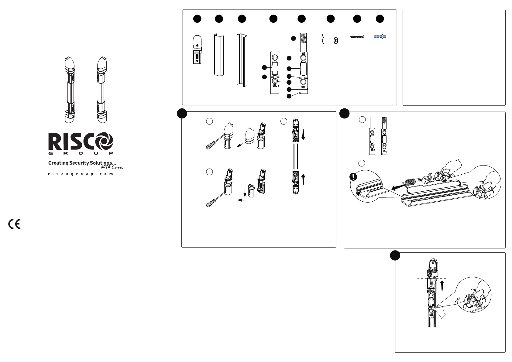
Tx Rail Rx Rail
A D E
B
x4
C
x1
1
5
+
6
4
6
I
4
5
3
TC
2
F
x1x2 x2
x2
+
G H
x4 x4
A. Rail holder
B. IR filter cover
C. Aluminum rail
D. Tx
E. Rx
12 34
ON
+
F. Battery
G. Screw
H. Dibble
1. Antenna
I
RC
2. Buzzer
3. Alarm LED
4. PCB Spring locker
5. IR Lens
6. Battery compartment
© RISCO Group 03/2012 5IN1526 B
RTTE Compliance Statement
Risco Ltd. hereby declares that this equipment is in compliance with the essential
requirements and other relevant provisions of Directive 1999/5/EC.
For the CE Declaration of Conformity please refer to our website: www.riscogroup.com.
All rights reserved. No part of this document may be reproduced in
any form without prior written permission from the publisher.
RISCO Group Contacting Info
RISCO Group is committed to customer service and product support. You can contact
us through our website (www.riscogroup.com) or at the following telephone and fax
numbers:
UK Tel: +44-(0)-161-655-5500
E-mail: support-uk@riscogroup.com
ITALY Tel: +39-02-66590054
E-mail: support-it@riscogroup.com
SPAIN Tel: +34-91-490-2133
E-mail: support-es@riscogroup.com
FRANCE Tel: +33-164-73-28-50
E-mail: support-fr@riscogroup.com
BELGIUM Tel: +32-2522-7622
E-mail: support-be@riscogroup.com
U.S.A Tel: +1-631-719-4400
E-mail: support-usa@riscogroup.com
BRAZIL Tel: +55-11-3661-8767
E-mail: support-br@riscogroup.com
CHINA (Shanghai) Tel: +86-21-52-39-0066
E-mail: support-cn@riscogroup.com
CHINA (Shenzhen) Tel: +86-755-82789285
E-mail: support-cn@riscogroup.com
POLAND Tel: +48-22-500-28-40
E-mail: support-pl@riscogroup.com
ISRAEL Tel: +972-3-963-7777
E-mail: support@riscogroup.com
FCC Note:
Only the 433,92 MHz version is FCC approved and to be sold in US.
The manufacturer is not responsible for any radio or TV interference caused by
unauthorized modifications to this equipment. Such modifications could void the user’s
authority to operate the equipment
1
A
C
2
A
+
I
TC
B
B
1. Separate the IR filter cover from the aluminum rail.
2. Place the rail holders on the top and bottom of both the Rx and Tx
aluminum rails as follows:
A. Take the rail holder and remove the cover (Fig.A)
B. Remove the swivel cover (Fig.B)
C. Slide the rail holder into the aluminum rail (Fig.C)
Place the Rx unit into one aluminum rail and the Tx unit into the second rail.
Important: 1. Pay attention to the units direction as indicated in the
drawings (Fig.A).
2. Pay attention that the units are correctly placed on the sliding
track (Fig.B).
RISCO Group Limited Warranty
RISCO Group and its subsidiaries and affiliates ("Seller") warrants its products to be free from defects in materials
and workmanship under normal use for 24 months from the date of production. Because Seller does not install or
connect the product and because the product may be used in conjunction with products not manufactured by the
Seller, Seller cannot guarantee the performance of the security system which uses this product. Seller's obligation
and liability under this warranty is expressly limited to repairing and replacing, at Seller's option, within a
reasonable time after the date of delivery, any product not meeting the specifications. Seller makes no other
warranty, expressed or implied, and makes no warranty of merchantability or of fitness for any particular purpose.
In no case shall seller be liable for any consequential or incidental damages for breach of this or any other
warranty, expressed or implied, or upon any other basis of liability whatsoever.
Seller's obligation under this warranty shall not include any transportation charges or costs of installation or any
liability for direct, indirect, or consequential damages or delay.
Seller does not represent that its product may not be compromised or circumvented; that the product will prevent
any personal injury or property loss by burglary, robbery, fire or otherwise; or that the product will in all cases
provide adequate warning or protection. Buyer understands that a properly installed and maintained alarm may
only reduce the risk of burglary, robbery or fire without warning, but is not insurance or a guaranty that such event
will not occur or that there will be no personal injury or property loss as a result thereof.
Consequently seller shall have no liability for any personal injury, property damage or loss based on a claim that
the product fails to give warning. However, if seller is held liable, whether directly or indirectly, for any loss or
damage arising under this limited warranty or otherwise, regardless of cause or origin, seller's maximum liability
shall not exceed the purchase price of the product, which shall be complete and exclusive remedy against seller.
No employee or representative of Seller is authorized to change this warranty in any way or grant any other
warranty.
WARNING: This product should be tested at least once a week.
12 34
ON
+
I
RC
3
Press the PCB Spring Lockers on the Rx and Tx units
and slide them towards the rail holders to the end of
the rail.
Page 2
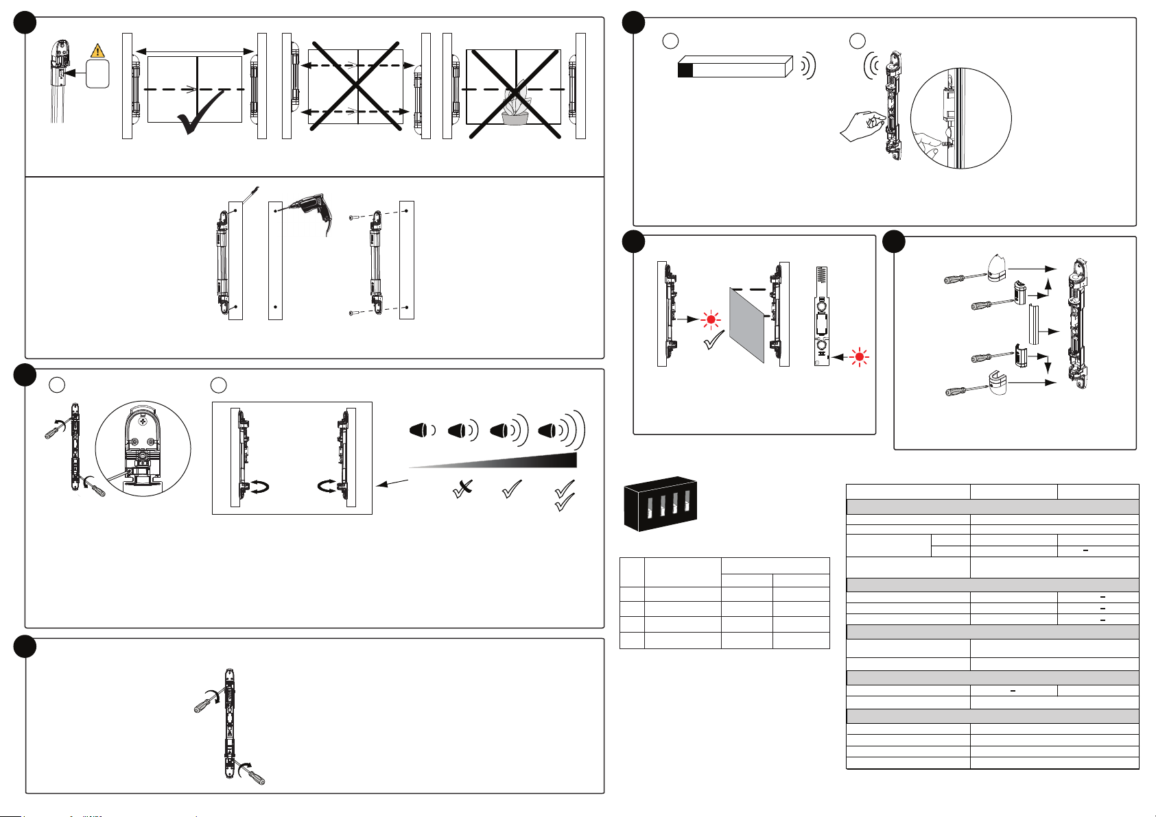
4
10m (32ft) max.
7
A B
Rx
TX
Select a mounting location. Make sure the TX / RX sticker is on the top of each rail.
Ø
8mm
Mount the Tx and Rx rails to the wall.
5
A
B
Rx Tx
EN PANEL (Learn Mode)
3 sec.
Set communication between the Rx and the security panel:
A. Set the panel to Learn mode.
B. Press the tamper spring for 5 seconds, verify that the detector has been identified by the panel.
8
Rx
Tx
Walk Test
Block both IR lens make sure alarm led in Rx rail
is ON.
+
I
RC
9
Tx + Rx
E
D
D
E
Close the Tx and Rx rails according to the A, B, C,
D, E order in the diagram above.
C
B
A
B
C
1. Insert the batteries first in the Tx unit then in The Rx unit.
2. Perform Rx-Tx beam alignment.
3. Listen to the buzzer for the maximum signal strength.
To improve signal strength:
A. Release the swivel locking screw on the top and bottom of both the Tx and Rx rails.
B. Swivel the Tx and Rx rails until maximum strength is received. Make sure you hear at least 3 beeps.
Notes: Installation mode will end after 4 minutes from power on or by pressing the Rx tamper switch.
To initiate the installation mode again: remove the battery for the Rx unit, wait and insert again.
Note: In the case of low battery, the red Alarm LED will flash 4 consecutive times.
6
Lock the swivel screws on both the Tx and Rx rails. Make sure that the alignment remains fixed.
Tx + Rx
Rx
ON
4
3
2
1
Rx control Dipswitch setting
No. Function Mode
OFF ON
1. RF transmission High* Low
2. Interruption Time 600mSec* 300mSec
Hold Status 2.5Min* Immediate
3i.
4. Spare OFF*
Default
*
i. For walk test purposes the hold-off time is
automaticlly activated during the first 10 minutes
after installation.
Technical Specifications
Receiver Transmitter
ELECTRICAL
Batteries
Battery Life
Current Consumption
@3.0V
Supervision transmission
RADIO FREQUENCY
RF Frequency
Modulation Type
Address Codes
PHYSICAL
Size (L x W x D)
Weight
OPTICAL
Infrared Wave Length
Detection range (Max.) 10m (32ft).
ENVIRONMENTAL
Operation Temperature
Storage Temperature
RF Immunity
IP Rating
Average
Maximum
CR123A, 3.0V Lithium Battery
3 years typical, depends on usage
30μA 20μA
30mA
For 868.65 MHz model: every 15 minutes
For 433.92 MHz model: every 65 minutes
433.92/868.65MHz
ASK
16 million
370 x 14.5 x 42 mm
(19.6 x 1.5 x 1.6 in.)
0.3kg (0.66LB) without batteries
-20°C to +60°C (4°F to 140°F)
-25°C to +60°C (13°F to 140°F)
According to EN 50130-4
IP65
940nm
 Loading...