


Air Conditioners
Air
RA14 Series
Rheem Classic® Series
Air Conditioners
•New composite base pan – dampens sound, captures louver panels, eliminates corrosion and reduces number of fasteners needed
•Powder coat paint system – for a long lasting professional finish
•Scroll compressor – uses 70% fewer moving parts for higher efficiency and increased reliability
•Modern cabinet aesthetics – increased curb appeal with visually appealing design
•Curved louver panels – provide ultimate coil protection, enhance cabinet strength, and increased cabinet rigidity
•Optimized fan orifice – optimizes airflow and reduces unit sound
•Rust resistant screws – confirmed through 1500-hour salt spray testing
•PlusOne™ Expanded Valve Space – 3"-4"-5" service valve space – provides a minimum working area of 27-square inches for easier access
•PlusOne™ Triple Service Access – 15" wide, industry leading corner service access – makes repairs easier and faster. The two fastener removable corner allows optimal access to internal unit components. Individual louver panels come out once fastener is removed, for faster coil cleaning and easier cabinet reassembly
RA14 Series
Efficiencies up to 16 SEER/13 EER
Nominal Sizes 11/2 to 5 Ton [5.28 to 17.6 kW] Cooling Capacities 17.3 to 60.5 kBTU
[5.7 to 17.7 kW]
16.0
“Proper sizing and installation of equipment is critical to achieve optimal performance. Ask your Dealer for details or visit www.energystar.gov.”
•Diagnostic service window with two-fastener opening – provides access to the high and low pressure.
•External gauge port access – allows easy connection of “low-loss” gauge ports
•Single-row condenser coil – makes unit lighter and allows thorough coil cleaning to maintain “out of the box” performance
•35% fewer cabinet fasteners and fastener-free base – allow for faster access to internal components and hassle-free panel removal
•Service trays – hold fasteners or caps during service calls
•QR code – provides technical information on demand for faster service calls
•Fan motor harness with extra long wires allows unit top to be removed without disconnecting fan wire.
FORM NO. A11-220 REV. 1

Table of Contents
Air
RA14 Series
TABLE OF CONTENTS |
|
Standard Feature ...................................................................................................... |
3 |
Available SKUs ........................................................................................................ |
3 |
Features & Benefits .............................................................................................. |
4-5 |
Model Number Identification ................................................................................ |
6-7 |
General Data/Electrical Data .................................................................................... |
8 |
Accessories ............................................................................................................ |
9 |
Weighted Sound Power ............................................................................................ |
9 |
Thermostats.............................................................................................................. |
9 |
Unit Dimensions...................................................................................................... |
10 |
Clearances.............................................................................................................. |
11 |
Wiring Diagrams .................................................................................................... |
12 |
Application Guidelines ............................................................................................ |
12 |
Refrigerant Line Size Information ...................................................................... |
13-14 |
Performance Data ............................................................................................ |
15-39 |
Guide Specifications .............................................................................................. |
40 |
Limited Warranty .................................................................................................... |
41 |
2

Standard Feature/Available SKUs
Air
RA14 Series
Standard Feature Table
|
|
STANDARD FEATURES |
|
|
|
|
|
Feature |
18 |
24 |
30 |
36 |
42 |
48 |
60 |
R-410a Refrigerant |
√ |
√ |
√ |
√ |
√ |
√ |
√ |
Maximum SEER |
16 |
16 |
16 |
16 |
16 |
15.5 |
15 |
Maximum EER |
13 |
13 |
13 |
13 |
13 |
13 |
12.5 |
Scroll Compressor |
√ |
√ |
√ |
√ |
√ |
√ |
√ |
Field Installed Filter Drier |
√ |
√ |
√ |
√ |
√ |
√ |
√ |
Front Seating Service Valves |
√ |
√ |
√ |
√ |
√ |
√ |
√ |
Internal Pressure Relief Valve |
√ |
√ |
√ |
√ |
√ |
√ |
√ |
Internal Thermal Overload |
√ |
√ |
√ |
√ |
√ |
√ |
√ |
Long Line capability |
√ |
√ |
√ |
√ |
√ |
√ |
√ |
Low Ambient capability with Kit |
√ |
√ |
√ |
√ |
√ |
√ |
√ |
3-4-5 Expanded Valve Space |
√ |
√ |
√ |
√ |
√ |
√ |
√ |
Composite Basepan |
√ |
√ |
√ |
√ |
√ |
√ |
√ |
2 Screw Control Box Access |
√ |
√ |
√ |
√ |
√ |
√ |
√ |
15" Access to Internal Components |
√ |
√ |
√ |
√ |
√ |
√ |
√ |
Quick release louver panel design |
√ |
√ |
√ |
√ |
√ |
√ |
√ |
No fasteners to remove along bottom |
√ |
√ |
√ |
√ |
√ |
√ |
√ |
Optimized Venturi Airflow |
√ |
√ |
√ |
√ |
√ |
√ |
√ |
Single row condenser coil |
√ |
√ |
√ |
√ |
√ |
√ |
√ |
Powder coated paint |
√ |
√ |
√ |
√ |
√ |
√ |
√ |
Rust resistant screws |
√ |
√ |
√ |
√ |
√ |
√ |
√ |
QR code |
√ |
√ |
√ |
√ |
√ |
√ |
√ |
External gauge ports |
√ |
√ |
√ |
√ |
√ |
√ |
√ |
Service trays |
√ |
√ |
√ |
√ |
√ |
√ |
√ |
√ = Standard
Available SKUs
Available Models |
Description |
RA1418AJ1NA |
Classic ® Series 1 1/2 ton 14 SEER Single-Stage Air Conditioner-208/230/1/60 |
RA1424AJ1NA |
Classic ® Series 2 ton 14 SEER Single-Stage Air Conditioner-208/230/1/60 |
RA1430AJ1NA |
Classic ® Series 2 1/2 ton 14 SEER Single-Stage Air Conditioner-208/230/1/60 |
RA1436AJ1NA |
Classic ® Series 3 ton 14 SEER Single-Stage Air Conditioner-208/230/1/60 |
RA1442AJ1NA |
Classic ® Series 3 1/2 ton 14 SEER Single-Stage Air Conditioner-208/230/1/60 |
RA1448AJ1NA |
Classic ® Series 4 ton 14 SEER Single-Stage Air Conditioner-208/230/1/60 |
RA1460AJ1NA |
Classic ® Series 5 ton 14 SEER Single-Stage Air Conditioner-208/230/1/60 |
RA1418AJ1NB |
Classic ® Series 1 1/2 ton 14 SEER Single-Stage Air Conditioner w/ High/Low Pressure-208/230/1/60 |
RA1424AJ1NB |
Classic ® Series 2 ton 14 SEER Single-Stage Air Conditioner w/ High/Low Pressure-208/230/1/60 |
RA1430AJ1NB |
Classic ® Series 2 1/2 ton 14 SEER Single-Stage Air Conditioner w/ High/Low Pressure-208/230/1/60 |
RA1436AJ1NB |
Classic ® Series 3 ton 14 SEER Single-Stage Air Conditioner w/ High/Low Pressure-208/230/1/60 |
RA1442AJ1NB |
Classic ® Series 3 1/2 ton 14 SEER Single-Stage Air Conditioner w/ High/Low Pressure-208/230/1/60 |
RA1448AJ1NB |
Classic ® Series 4 ton 14 SEER Single-Stage Air Conditioner w/ High/Low Pressure-208/230/1/60 |
RA1460AJ1NB |
Classic ® Series 5 ton 14 SEER Single-Stage Air Conditioner w/ High/Low Pressure-208/230/1/60 |
RA1436AC1NB |
Classic ® Series 3 ton 14 SEER Single-Stage Air Conditioner w/ High/Low Pressure-208/230/3/60 |
RA1442AC1NB |
Classic ® Series 3 1/2 ton 14 SEER Single-Stage Air Conditioner w/ High/Low Pressure-208/230/3/60 |
RA1448AC1NB |
Classic ® Series 4 ton 14 SEER Single-Stage Air Conditioner w/ High/Low Pressure-208/230/3/60 |
RA1460AC1NB |
Classic ® Series 5 ton 14 SEER Single-Stage Air Conditioner w/ High/Low Pressure-208/230/3/60 |
RA1436AD1NB |
Classic ® Series 3 ton 14 SEER Single-Stage Air Conditioner w/ High/Low Pressure-460/3/60 |
RA1442AD1NB |
Classic ® Series 3 1/2 ton 14 SEER Single-Stage Air Conditioner w/ High/Low Pressure-460/3/60 |
RA1448AD1NB |
Classic ® Series 4 ton 14 SEER Single-Stage Air Conditioner w/ High/Low Pressure-460/3/60 |
RA1460AD1NB |
Classic ® Series 5 ton 14 SEER Single-Stage Air Conditioner w/ High/Low Pressure-460/3/60 |
|
|
3
Features & Benefits
Air
RA14 Series
Introduction to RA14 Air Conditioner
The RA14 is our 14 SEER air conditioner and is part of the Rheem air conditioner product line that extends from 13 to 20 SEER. This highly featured and reliable air conditioner is designed for years of reliable, efficient operation when matched with Rheem indoor aluminum evaporator coils and furnaces or air handler units with aluminum evaporators.
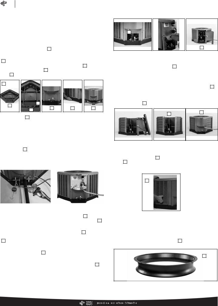
Our unique composite base ( 1 ) reduces sound emission, eliminates rattles, significantly reduces fasteners, eliminates corrosion and has integrated brass compressor attachment inserts
( 2 ). Furthermore it has incorporated into the design, water management features, means for hand placement ( 3 ) for unit maneuvering, screw trays ( 4 ) and inserts for lifting off unit pad. ( 5 )
1 |
|
|
2 |
|
|
4 |
|
|
6 |
3 |
5 |
4 |
|
|
Service Valves ( 6 ) are rigidly mounted in the composite base with 3" between suction and discharge valves, 4" clearance below service valves and a minimum of 5" above the service valves, creating industry leading installation ease. The minimum 27 square-inches around the service valves allows ample room to remove service valve schrader prior to brazing, plenty of clearance for easy brazing of the suction and discharge lines to service valve outlets, easy access and hookup of low loss refrigerant gauges ( 7 ), and access to the service valve caps for opening. For applications with long-line lengths up to 250 feet total equivalent length, up to 200 feet condenser above evaporator, or up to 80 feet evaporator above condenser, the long-line instructions in the installation manual should be followed.
|
|
|
|
|
|
|
|
|
|
7 |
|
|
|
8 |
|
11 |
|
|
|
|
|
|||||
|
|
|
|
|
|
|
|
|
|
|
|
|
|
|
|
|
|
|
|
|
|
|
10 |
|
9 |
|
|
|
|
|
|
|
|
|
|
|
|
|
|
|
|
|
|
|
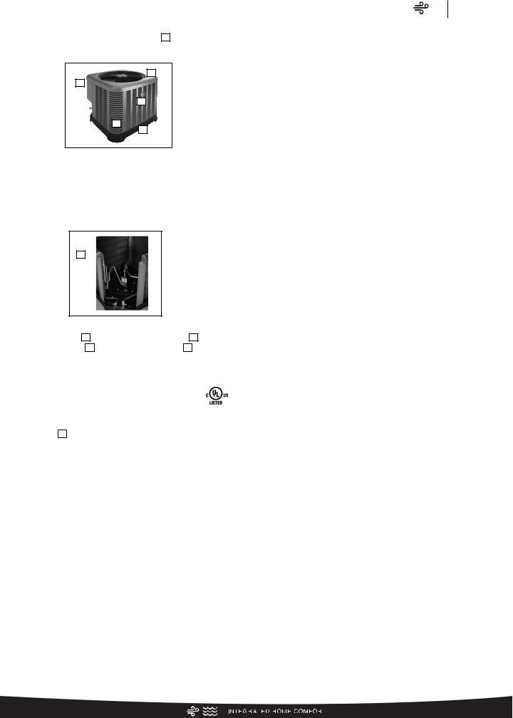
Controls are accessed from the corner of the unit by removing only two fasteners from the control access cover, revealing the industry’s largest 15" wide and 14" tall control area ( 8 ). With all this room in the control area the high voltage electrical whip ( 9 )
can easily be inserted through the right size opening in the bottom of the control area. Routing it leads directly to contractor lugs for connection. The low voltage control wires ( 10 ) are easily connected to units low voltage wiring. If contactor or capacitor ( 11 ) needs to be replaced there is more than adequate space to
make the repair. Furthermore, if high pressure and low pressure model was not purchased but is desired to be installed in the field, the service window ( 12 ) can be removed by removing two
screws, to access the high and low side schrader fittings for easy field installation. The entire corner can be removed providing ultimate access to install the high and low pressure switch. ( 13 )
4
12
13
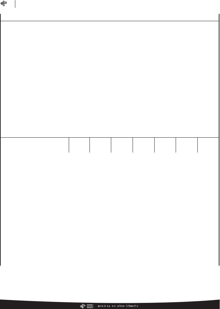
If in the rare event, greater access is needed to internal components, such as the compressor, the entire corner of the unit can be removed along with the top cover assembly to have unprecedented access to interior of the unit ( 14 ). Extra wire length is incorporated into each outdoor fan and compressor so top cover and control panel can be positioned next to the unit. With minimal effort the plug can be removed from the compressor and the outdoor fan wires can be removed from the capacitor to allow even more uncluttered access to the interior of the unit ( 15 ). Outdoor coil heights range from as short as 22" to 32", aiding access to the compressor. Disassembly to this degree and complete reassembly only takes a first time service technician less than 10 minutes. ( 15 )
18
16
14 |
|
15 |
|
|
|
All units utilize strong formed louver panels which provide industry leading coil protection. Louver removal for coil cleaning is accomplished by removing one screw and lifting the panel out of the composite base pan. ( 17 ) All RA14 units utilize single row coils ( 16 ) making cleaning easy and complete, restoring the performance of the air conditioner back to out of the box performance levels year after year.
17
The outdoor fan motor has sleeve bearings and is inherently protected. The motor is totally enclosed for maximum protection from weather, dust and corrosion. Access to the outdoor fan is made by removing four fasteners from the fan grille. The outdoor fan can be removed from the fan grille by removing 4 fasteners in the rare case outdoor fan motor fails.
Each cabinet has optimized composite ( 19 ) fan orifice assuring efficient and quiet airflow.
19
The entire cabinet has powder post paint ( 20 ) achieving 1000
hour salt spray rating, allowing the cabinet to retain its aesthetics throughout its life.
24
20
23
22
21
Scroll compressors with standard internal pressure relief and internal thermal overload are used on all capacities assuring longevity of high efficient and quiet operation for the life of the product.
Each unit is shipped with filter drier for field installation and will trap any moisture or dirt that could contaminate the refrigerant system.
25
All cabinets have industry leading structural strength due to the composite base pan ( 21 ), interlocking corner post ( 22 ), formed curved louver panels ( 23 ) and drawn top cover ( 24 ) making it
the most durable cabinet on the market today.
Each RA14 capacity has undergone rigorous psychometric testing to assure performance ratings of capacity, SEER
and EER per AHRI Standard 210/240 rating conditions. Also each unit bears the UL mark and each unit is certified to UL 1995 safety standards.
Each unit has undergone specific strain and modal testing to assure tubing ( 25 ) is outside the units natural frequency and that the suction and discharge lines connected to the compressor withstand any starting, steady state operation or shut down forces imposed by the compressor.
All units have been sound tested in sound chamber to AHRI 270 rating conditions, and A-weighted Sound Power Level tables produced, assuring units have acceptable noise qualities (see page 8). Each unit has been ran in cooling operation at 95°F and 82°F and sound ratings for the RA14 range from as low as 74 dBA to 77 dBA.
All units have been ship tested to assure units meet stringent “over the road” shipping conditions.
As manufactured all units in the RA14 family have cooling capability to 55 °F. Addition of low ambient control will allow the unit to operate down to 0°F. Factory testing is performed on each unit. All component parts meet well defined specification and continually go through receiving inspections. Each component installed on a unit is scanned, assuring correct component utilization for a given unit capacity and voltage. All condenser coils are leak tested with pressurization test to 550#’s and once installed and assembled, each units’ complete refrigerant system is helium leak tested. All units are fully charged from the factory for up to 15 feet of piping. All units are factory run tested. The RA14 has a 10-year conditional compressor and parts warranty (registration required).
Features & Benefits
Air
RA14 Series
Optional Accessories
(Refer to accessory chart for model #)
Compressor Crankcase Heater
Protects against refrigerant migration that can occur during low ambient operation
Compressor Sound Cover
•Reinforced vinyl compressor cover containing a 1½ inch thick batt of fiberglass insulation
•Open edges are sealed with a one-inch wide hook and loop fastening tape
Compressor Hard Start Kit
•Single-phase units are equipped with a PSC compressor motor, this type of motor normally does not need a potential relay and start capacitor
•Kit may be required to increase the compressor starting torque, in conditions such as low voltage
Low Ambient Kit
•Air conditioners operate satisfactorily in the cooling mode down to 55°F outdoor air temperature without any additional controls
•This Kit can be added in the field enabling unit to operate properly down to 0° in the cooling mode
•Crankcase heater and freezestat should be installed on compressors equipped with a low ambient kit
3"/6"/12"
•Gray high density polyethylene feet are available to raise unit off of mounting surface away from moisture
Low Pressure
•Can be added in field enabling the unit to shut off compressor on loss of charge
NOTE: Unit can be purchased with high and low pressure installed at factory. (Refer to SKU list)
High Pressure
•Can be added in field enabling unit to shut off compressor if unit loses outdoor fan operation.
NOTE: Unit can be purchased with high and low pressure installed at factory. (Refer to SKU list)
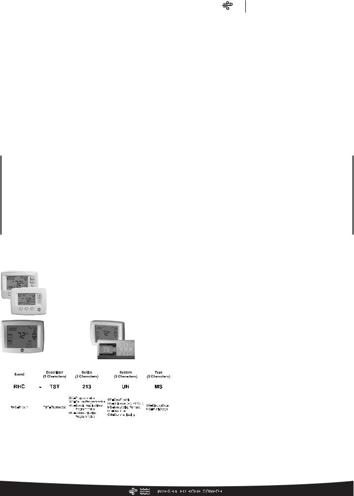
Decorative Top
• Can be installed on fan grille
5

6
Air Conditioners
|
R |
A |
14 |
|
|
24 |
|
A |
J |
1 |
|
|
N |
A |
* |
|
||||||||||||||
|
|
|
|
|
|
|
|
|
|
|
|
|
|
|
|
|
|
|
|
|
|
|
|
|
|
|
|
|
||
Brand |
Product |
SEER |
|
Capacity |
Major Series* |
Voltage |
Type |
Controls |
Minor Series** |
Option |
||||||||||||||||||||
|
|
|
Category |
|
|
|
|
BTU/HR |
|
|
|
|
|
|
|
|
|
|
|
|
|
|
|
Code |
||||||
Rheem |
A - Air Conditioners |
13 - 13 SEER |
18 |
- 18,000 |
[5.28 kW] A - 1st Design |
J - 1ph, 208-230/60 |
1 - Single-stage |
C - Communicating |
A - 1st Design |
N/A |
||||||||||||||||||||
|
|
|
|
|
|
14 - 14 SEER |
24 |
- 24,000 |
[7.03 kW] |
|
|
|
C - 3ph, 208-230/60 |
2 - Two-stage |
N - Non-Communicating |
|
|
|
|
|
|
|||||||||
|
|
|
|
|
|
16 - 16 SEER |
30 |
- 30,000 |
[8.79 kW] |
|
|
|
D - 3ph, 460/60 |
V - Inverter |
|
|
|
|
|
|
|
|
|
|||||||
|
|
|
|
|
|
17 - 17 SEER |
36 |
- 36,000 [10.55 kW] |
|
|
|
|
|
|
|
|
|
|
|
|
|
|
|
|
|
|
||||
|
|
|
|
|
|
20 - 20 SEER |
42 |
- 42,000 [12.31 kW] |
|
|
|
|
|
|
|
|
|
|
|
|
|
|
|
|
|
|
||||
|
|
|
|
|
|
|
|
|
48 |
- 48,000 [14.07 kW] |
|
|
|
|
|
|
|
|
|
|
|
|
|
|
|
|
|
|
||
|
|
|
|
|
|
|
|
|
60 |
- 60,000 [17.58 kW] |
|
|
|
|
|
|
|
|
|
|
|
|
|
|
|
|
|
|
||
|
Air |
|
|
Series RA14 |
Number Model |
|
Identification |
Heat Pumps (For Reference)
|
R |
A |
14 |
|
|
24 |
|
|
A |
J |
1 |
|
N |
A |
* |
|
||||||||||||||
|
|
|
|
|
|
|
|
|
|
|
|
|
|
|
|
|
|
|
|
|
|
|
|
|
|
|
|
|
||
Brand |
Product |
SEER |
|
Capacity |
Major Series* |
Voltage |
Type |
Controls |
Minor Series** |
Option |
||||||||||||||||||||
|
|
|
Category |
|
|
|
|
BTU/HR |
|
|
|
|
|
|
|
|
|
|
|
|
|
|
|
Code |
||||||
Rheem |
P - Heat Pump |
13 - 13 SEER |
18 |
- 18,000 |
[5.28 kW] |
A - 1st Design |
J - 1ph, 208-230/60 |
1 - Single-stage |
C - Communicating |
A - 1st Design |
N/A |
|||||||||||||||||||
|
|
|
|
|
|
14 - 14 SEER |
24 |
- 24,000 |
[7.03 kW] |
|
|
|
C - 3ph, 208-230/60 |
2 - Two-stage |
N - Non-Communicating |
|
|
|
|
|
|
|||||||||
|
|
|
|
|
|
16 - 16 SEER |
30 |
- 30,000 |
[8.79 kW] |
|
|
|
D - 3ph, 460/60 |
V - Inverter |
|
|
|
|
|
|
|
|
|
|||||||
|
|
|
|
|
|
17 - 17 SEER |
36 |
- 36,000 [10.55 kW] |
|
|
|
|
|
|
P - Piston |
|
|
|
|
|
|
|
|
|
||||||
|
|
|
|
|
|
20 - 20 SEER |
42 |
- 42,000 [12.31 kW] |
|
|
|
|
|
|
|
|
|
|
|
|
|
|
|
|
|
|
||||
|
|
|
|
|
|
|
|
|
48 |
- 48,000 [14.07 kW] |
|
|
|
|
|
|
|
|
|
|
|
|
|
|
|
|
|
|
||
|
|
|
|
|
|
|
|
|
60 |
- 60,000 [17.58 kW] |
|
|
|
|
|
|
|
|
|
|
|
|
|
|
|
|
|
|
||
Furnace Coils (For Reference)
|
R |
|
C |
|
F |
|
24 |
|
|
17 |
|
S |
|
T |
|
A |
M |
|
C |
|
A |
* |
|
|||||||||||||
|
|
|
|
|
|
|
|
|
|
|
|
|
|
|
|
|
|
|
|
|
|
|
|
|
|
|
|
|
|
|
|
|
|
|
||
Brand |
Product |
Type |
|
Capacity |
Width |
Efficiency |
Metering |
Major |
Orientation |
Casing |
Minor Series** |
Option |
||||||||||||||||||||||||
|
|
|
Category |
|
|
|
|
BTU/HR |
|
|
|
|
|
|
Device |
Series* |
|
|
|
|
|
|
|
|
|
Code |
||||||||||
Rheem |
C - Evap Coil |
F - Furn Coil |
24 |
- 24,000 [7.03 kW] |
14 |
- 14" |
S- Standard Eff. |
T-TXV |
A - 1st Design |
M - Multipoise |
C - Cased |
A - 1st Design |
N/A |
|||||||||||||||||||||||
|
|
|
|
|
|
H - Air-Handler |
36 |
- 36,000 [10.55 kW] |
17 |
- 17.5" |
M- Mid Eff. |
E-EEV |
|
|
|
V - Vertical only/ |
U - Uncased |
|
|
|
|
|
|
|||||||||||||
|
|
|
|
|
|
Coil |
48 |
- 48,000 [14.07 kW] |
21 |
- 21" |
H- High Eff. |
P-Piston |
|
|
|
convertible |
|
|
|
|
|
|
|
|
|
|||||||||||
|
|
|
|
|
|
|
|
|
60 |
- 60,000 [17.58 kW] |
24 |
- 24.5" |
|
|
|
|
|
|
|
|
|
H - Ded. |
|
|
|
|
|
|
|
|
|
|||||
|
|
|
|
|
|
|
|
|
|
|
|
|
|
|
|
|
|
|
|
|
|
|
|
|
Horizontal only |
|
|
|
|
|
|
|
|
|
||
[ ] Designates Metric Conversions

90%+ AFUE Gas Furnaces (For Reference)
|
R |
|
96 |
|
V |
|
A |
|
|
70 |
|
|
|
2 |
|
|
3 |
|
|
17 |
|
|
M |
S |
|
A |
|||||||||||
|
|
|
|
|
|
|
|
|
|
|
|
|
|
|
|
|
|
|
|
|
|
|
|
|
|
|
|
|
|
|
|
|
|
|
|||
Brand |
Series |
Motor |
Major Rev |
|
|
Input |
|
Stages |
|
Air Flow |
Cabinet |
Configuration |
Nox |
Minor Rev |
|||||||||||||||||||||||
|
|
|
|
|
|
|
|
|
|
|
|
|
|
BTU/HR |
|
|
|
|
|
|
|
|
Width |
|
|
|
|
|
|
|
|
|
|||||
Rheem |
90 - 90 AFUE |
V - Variable speed |
A - 1st Design |
040 |
- |
42,000 |
[12.31 kW] |
1 |
- Single-stage |
3 |
- up to 3 ton |
14 |
- 14" |
M - Multi |
X - Low Nox |
A - 1st Design |
|||||||||||||||||||||
|
|
|
92 - 92 AFUE |
T - Constant |
|
|
|
060 |
- |
56,000 |
[16.41 kW] |
2 |
- Two-stage |
5 |
- 3 1/2 up to 5 ton |
17 |
- 17.5" |
|
|
|
S - Standard |
|
|
|
|||||||||||||
|
|
|
95 - 95 AFUE |
Torque |
|
|
|
070 |
- |
70,000 |
[20.51 kW] |
M - Modulating |
|
|
|
|
21 |
- 21" |
|
|
|
|
|
|
|
|
|
||||||||||
|
|
|
96 - 96 AFUE |
(X-13) |
|
|
|
085 |
- |
84,000 |
[24.62 kW] |
|
|
|
|
|
|
|
|
24 |
- 24.5" |
|
|
|
|
|
|
|
|
|
|||||||
|
|
|
97 - 97 AFUE |
P - PSC |
|
|
|
100 |
- |
98,000 |
[28.72 kW] |
|
|
|
|
|
|
|
|
|
|
|
|
|
|
|
|
|
|
|
|
||||||
|
|
|
|
|
|
|
|
|
|
|
|
115 |
- 112,000 [32.82 kW] |
|
|
|
|
|
|
|
|
|
|
|
|
|
|
|
|
|
|
|
|
||||
80% AFUE Gas Furnaces (For Reference)
R |
80 |
|
2 |
V |
A |
|
075 |
|
|
|
|
3 |
17 |
|
|
M |
S |
|
A |
||||||||||||||||||
|
|
|
|
|
|
|
|
|
|
|
|
|
|
|
|
|
|
|
|
|
|
|
|
|
|
|
|
|
|
|
|
|
|
|
|
|
|
Brand |
Series |
Stages |
Motor |
Major Rev |
|
Input |
|
|
|
Air Flow |
Cabinet |
Configuration |
Nox |
Minor Rev |
|||||||||||||||||||||||
|
|
|
|
|
|
|
|
|
|
|
|
|
|
|
|
BTU/HR |
|
|
|
|
|
Width |
|
|
|
|
|
|
|
|
|
|
|||||
Rheem |
80 - 80+ AFUE 1 |
- Single-stage |
V - Variable speed |
A - 1st Design 050 - |
50,000 |
[15 kW] |
3 |
- up to 3 ton |
14 |
- 14" |
M - Multi |
X - Low Nox |
A - 1st Design |
||||||||||||||||||||||||
|
|
|
2 |
- Two-stage |
T - Constant Torque (X-13) |
075 |
- |
75,000 |
[22 kW] |
4 |
- 2 |
1/2 to 4 ton |
17 |
- 17.5" |
D |
- Down |
S - Standard |
|
|
|
|||||||||||||||||
|
|
|
|
|
|
|
|
|
P - PSC premium |
100 |
- 100,000 [29 kW] |
5 |
- 3 |
1/2 up to 5 ton |
21 |
- 21" |
Z |
- Down & |
|
|
|
|
|
|
|||||||||||||
|
|
|
|
|
|
|
|
|
S - PSC standard |
125 |
- 125,000 [37 kW] |
|
|
|
|
|
24 |
- 24.5" |
|
zero clearance |
|
|
|
|
|
|
|||||||||||
|
|
|
|
|
|
|
|
|
|
|
|
150 |
- 150,000 [44 kW] |
|
|
|
|
|
|
|
|
|
down flow |
|
|
|
|
|
|
||||||||
|
|
|
|
|
|
|
|
|
|
|
|
|
|
|
|
|
|
|
|
|
|
|
|
|
|
|
|
|
|
|
|
|
|
|
|
|
|
Air Handlers (For Reference)
R |
|
H |
|
1 |
T |
|
36 |
|
17 |
|
S |
T |
|
A |
N |
|
A |
|
A |
000 |
|
* |
|
|||||||||||||||||||||
|
|
|
|
|
|
|
|
|
|
|
|
|
|
|
|
|
|
|
|
|
|
|
|
|
|
|
|
|
|
|
|
|
|
|
|
|
|
|
|
|
|
|
|
|
Brand |
Product |
|
Stages of |
Motor Type |
|
Capacity |
Width |
Coil Size |
Metering |
Major |
Controls |
Voltage |
Minor |
Factory Heat |
Option |
|||||||||||||||||||||||||||||
|
|
|
Category |
|
Airflow |
|
|
|
|
BTU/HR |
|
|
|
|
|
|
|
Device |
Series* |
|
|
|
|
|
|
Series** |
|
Cap |
Code |
|||||||||||||||
Rheem |
H - Air |
1 |
- Single-Stage |
V - Variable |
24 |
- 24,000 [7.03 kW] |
14 |
- 14" |
S - Standard |
T - TEV |
A - 1st Design |
C -Communicating |
A - 1ph, 115/60 |
A - 1st Design |
00 - no |
*TBD |
||||||||||||||||||||||||||||
|
|
|
Handler |
2 |
- Two-Stage |
Speed |
36 |
- 36,000 [10.55 kW] |
17 |
- 17.5" |
Eff. |
E - EEV |
|
|
|
N -Non-comm |
J - 1ph, 208-240/60 |
|
|
|
factory heat |
|
|
|
||||||||||||||||||||
|
|
|
|
|
|
M - Modulating T - Constant |
48 |
- 48,000 [14.07 kW] |
21 |
- 21" |
M -Mid Eff. |
P - Piston |
|
|
|
|
|
|
D - 3ph, 480/60 |
|
|
|
with option |
|
|
|
||||||||||||||||||
|
|
|
|
|
|
|
|
|
|
Torque |
60 |
- 60,000 [17.58 kW] |
24 |
- 24.5" |
H - High Eff. |
|
|
|
|
|
|
|
|
|
|
|
|
|
|
|
code |
|
|
|
||||||||||
|
|
|
|
|
|
|
|
|
|
P - PSC |
|
|
|
|
|
|
|
|
|
|
|
|
|
|
|
|
|
|
|
|
|
|
|
|
|
|
|
|
|
|
|
|
||
|
|
|
|
|
|
|
|
|
|
|
|
|
|
|
|
|
|
|
|
|
|
|
|
|
|
|
|
|
|
|
|
|
|
|
|
|
|
|
|
|
|
|
|
|
[ ] Designates Metric Conversions
7
|
Air |
|
|
Series RA14 |
Number Model |
|
Identification |
General Data/Electrical Data
Air
RA14 Series
Physical Data
PHYSICAL DATA
|
Model No. |
RA1418A |
RA1424A |
RA1430A |
RA1436A |
RA1442A |
RA1448A |
RA1460A |
|
|
Nominal Tonnage |
1.5 |
2.0 |
2.5 |
3.0 |
3.5 |
4.0 |
5.0 |
|
|
Valve Connections |
|
|
|
|
|
|
|
|
|
Liquid Line O.D. – in. |
3/8 |
3/8 |
3/8 |
3/8 |
3/8 |
3/8 |
3/8 |
|
|
Suction Line O.D. – in. |
3/4 |
3/4 |
3/4 |
3/4 |
7/8 |
7/8 |
7/8 |
|
|
Refrigerant (R410A) furnished oz.¹ |
68 |
72 |
93 |
112 |
119 |
135 |
162 |
|
|
Compressor Type |
|
|
|
Scroll |
|
|
|
|
|
Outdoor Coil |
|
|
|
|
|
|
|
|
|
Net face area – Outer Coil |
9.1 |
11.1 |
12.1 |
14.8 |
16.1 |
18.9 |
21.5 |
|
|
Net face area – Inner Coil |
— |
— |
— |
— |
— |
— |
— |
|
|
Tube diameter – in. |
3/8 |
3/8 |
3/8 |
3/8 |
3/8 |
3/8 |
3/8 |
|
|
Number of rows |
1 |
1 |
1 |
1 |
1 |
1 |
1 |
|
|
Fins per inch |
20 |
20 |
20 |
20 |
20 |
20 |
20 |
|
|
Outdoor Fan |
|
|
|
|
|
|
|
|
|
Diameter – in. |
20 |
20 |
20 |
24 |
26 |
26 |
26 |
|
|
Number of blades |
2 |
2 |
2 |
3 |
2 |
2 |
3 |
|
|
Motor hp |
1/10 |
1/8 |
1/5 |
1/6 |
1/5 |
1/10 |
1/5 |
|
|
CFM |
2225 |
2505 |
2605 |
3105 |
4265 |
4265 |
4140 |
|
|
RPM |
1075 |
1070 |
1075 |
850 |
820 |
820 |
850 |
|
|
watts |
130 |
163 |
142 |
173 |
240 |
236 |
255 |
|
|
Shipping weight – lbs. |
125 |
125 |
148 |
157 |
199 |
200 |
210 |
|
|
Operating weight – lbs. |
122 |
125 |
141 |
150 |
192 |
192 |
202 |
|
|
Electrical Data |
|
|
|
|
|
|
|
|
|
|
|
|
|
|
|
|
|
|
Line Voltage Data (Volts-Phase-Hz) |
208/230-1-60 |
208/230-1-60 |
208/230-1-60 |
208/230-1-60 |
208/230-1-60 |
208/230-1-60 208/230-1-60 |
|
Maximum overcurrent protection (amps)² |
20 |
25 |
25 |
30 |
40 |
45 |
50 |
Minimum circuit ampacity³ |
13 |
15 |
17 |
19 |
24 |
26 |
40 |
Compressor |
|
|
|
|
|
|
|
Rated load amps |
9.7 |
11.2 |
12.8 |
14.1 |
17.9 |
19.9 |
23.7 |
Locked rotor amps |
46 |
60.8 |
64 |
77 |
112 |
109 |
152.5 |
Condenser Fan Motor |
|
|
|
|
|
|
|
Full load amps |
0.6 |
0.7 |
0.7 |
0.6 |
1 |
1 |
1 |
Locked rotor amps |
1.1 |
1.2 |
1.3 |
1.5 |
2.3 |
2.3 |
2.3 |
Line Voltage Data (Volts-Phase-Hz) |
— |
— |
— |
208/230-3-60 |
208/230-3-61 |
208/230-3-62 |
208/230-3-63 |
Maximum overcurrent protection (amps)² |
— |
— |
— |
20 |
30 |
30 |
35 |
Minimum circuit ampacity³ |
— |
— |
— |
12 |
18 |
18 |
21 |
Compressor |
|
|
|
|
|
|
|
Rated load amps |
— |
— |
— |
8 |
13.2 |
13.1 |
15.9 |
Locked rotor amps |
— |
— |
— |
71 |
88 |
110 |
110 |
Condenser Fan Motor |
|
|
|
|
|
|
|
Full load amps |
— |
— |
— |
0.6 |
1 |
1 |
1 |
Locked rotor amps |
— |
— |
— |
6.5 |
2.3 |
2.3 |
2.3 |
Line Voltage Data (Volts-Phase-Hz) |
— |
— |
— |
480-3-60 |
480-3-60 |
480-3-60 |
480-3-60 |
Maximum overcurrent protection (amps)² |
— |
— |
— |
TBD |
TBD |
TBD |
TBD |
³Minimum circuit ampacity |
— |
— |
— |
TBD |
TBD |
TBD |
TBD |
Compressor |
|
|
|
|
|
|
|
Rated load amps |
— |
— |
— |
TBD |
TBD |
TBD |
TBD |
Locked rotor amps |
— |
— |
— |
TBD |
TBD |
TBD |
TBD |
Condenser Fan Motor |
|
|
|
|
|
|
|
Full load amps |
— |
— |
— |
TBD |
TBD |
TBD |
TBD |
Locked rotor amps |
— |
— |
— |
TBD |
TBD |
TBD |
TBD |
¹Refrigerant charge sufficient for 15 ft. length of refrigerant lines. For longer line set requirements see the installation instructions for information about set length and additional refrigerant charge required.
²HACR type circuit breaker of fuse.
³Refer to National Electrical Code manual to determine wire, fuse and disconnect size requirements.
8
Accessories/Weighted Sound Power/Thermostats
Air
RA14 Series
Accessories
Model No. |
RA1418 |
RA1424 |
RA1430 |
RA1436 |
RA1442 |
RA1448 |
RA1460 |
|
|
|
|
|
|
|
|
|
|
Compressor crankcase heater* |
44-17402-44 |
44-17402-44 |
44-17402-44 |
44-17402-44 |
44-17402-45 |
44-17402-45 |
44-17402-45 |
|
|
|
|
|
|
|
|
|
|
Low ambient control |
|
RXAD-A08 |
RXAD-A08 |
RXAD-A08 |
RXAD-A08 |
RXAD-A08 |
RXAD-A08 |
RXAD-A08 |
|
|
|
|
|
|
|
|
|
Compressor sound cover |
|
68-23427-26 |
68-23427-26 |
68-23427-26 |
68-23427-26 |
68-23427-25 |
68-23427-25 |
68-23427-25 |
|
|
|
|
|
|
|
|
|
Compressor hard start kit |
|
SK-A1 |
SK-A1 |
SK-A1 |
SK-A1 |
SK-A1 |
SK-A1 |
SK-A1 |
|
|
|
|
|
|
|
|
|
Low pressure control |
|
RXAC-A07 |
RXAC-A07 |
RXAC-A07 |
RXAC-A07 |
RXAC-A07 |
RXAC-A07 |
RXAC-A07 |
|
|
|
|
|
|
|
|
|
High pressure control |
|
RXAB-A07 |
RXAB-A07 |
RXAB-A07 |
RXAB-A07 |
RXAB-A07 |
RXAB-A07 |
RXAB-A07 |
Liquid Line Solenoid |
Solenoid Valve |
200RD2T3TVLC |
200RD2T3TVLC |
200RD2T3TVLC |
200RD2T3TVLC |
200RD2T3TVLC |
200RD3T3TVLC |
200RD3T3TVLC |
(24 VAC, 50/60 Hz) |
Solenoid Coil |
61-AMG24V |
61-AMG24V |
61-AMG24V |
61-AMG24V |
61-AMG24V |
61-AMG24V |
61-AMG24V |
|
|
|
|
|
|
|
|
|
Liquid Line Solenoid |
Solenoid Valve |
200RD2T3TVLC |
200RD2T3TVLC |
200RD2T3TVLC |
200RD2T3TVLC |
200RD2T3TVLC |
200RD3T3TVLC |
200RD3T3TVLC |
(120/240 VAC, 50/60 Hz) |
Solenoid Coil |
61-AMG120/240V |
61-AMG120/240V |
61-AMG120/240V |
61-AMG120/240V |
61-AMG120/240V |
61-AMG120/240V |
61-AMG120/240V |
Classic Top Cap w/Label |
|
91-101123-21 |
91-101123-21 |
91-101123-21 |
91-101123-21 |
91-101123-21 |
91-101123-21 |
91-101123-21 |
|
|
|
|
|
|
|
|
|
*Crankcase Heater recommended with Low Ambient Kit.
Weighted Sound Power Level (dBA)
A-WEIGHTED SOUND POWER LEVEL (dBA)
Unit Size - Voltage, Series |
Standard Rating |
|
TYPICAL OCTAVE BAND SPECTRUM (dBA without tone adjustment) |
|
||||
(dBA) |
125 |
250 |
500 |
1000 |
2000 |
4000 |
||
|
||||||||
RA1418A |
76 |
52.9 |
61.1 |
65 |
65.7 |
62.7 |
58.1 |
|
RA1424A |
75 |
52.6 |
59.3 |
65.3 |
65.7 |
62.4 |
57.9 |
|
RA1430A |
74 |
48.8 |
57.5 |
63.5 |
64 |
61.9 |
56.1 |
|
RA1436A |
76 |
51.6 |
57.5 |
64.3 |
67.6 |
64.9 |
58.6 |
|
RA1442A |
76 |
54.9 |
61.5 |
65.3 |
66.3 |
62.8 |
59.5 |
|
RA1448A |
76 |
52.3 |
59.1 |
66.7 |
65.7 |
62.4 |
59.3 |
|
RA1460A |
75 |
53.4 |
59.1 |
65.9 |
66.9 |
62.8 |
58.7 |
|
NOTE: Tested in accordance with AHRI Standard 270-08 (not listed in AHRI)
Thermostats
200-Series *
Programmable
|
|
300-Series * |
|
|
|
|
|
|
500-Series * |
|||||||||||||||
|
|
Deluxe |
|
|
|
|
|
|
Communicating/ |
|||||||||||||||
|
|
Programmable |
|
|
|
|
|
|
Programmable |
|||||||||||||||
|
|
400-Series * |
|
|
|
|
|
|
|
|
|
|
|
|
||||||||||
|
|
Special Applications/ |
|
|
|
|
|
|
|
|
|
|
|
|
||||||||||
|
|
Programmable |
|
|
|
|
|
|
|
|
|
|
|
|
||||||||||
|
|
|
|
|
|
|
|
|
|
|
|
|
|
|
|
|
|
|
|
|
|
|
|
|
|
|
|
|
|
|
|
|
|
|
|
|
|
|
|
|
|
|
|
|
|
|
|
|
|
|
|
|
|
|
|
|
|
|
|
|
|
|
|
|
|
|
|
|
|
|
|
|
|
|
|
|
|
|
|
|
|
|
|
|
|
|
|
|
|
|
|
|
|
|
|
|
|
|
|
|
|
|
|
|
|
|
|
|
|
|
|
|
|
|
|
|
|
|
|
|
|
|
|
|
|
|
|
|
|
|
|
|
|
|
|
|
|
|
|
|
|
|
|
|
|
|
|
|
|
|
|
|
|
|
|
|
|
|
|
|
|
|
|
|
|
|
|
|
|
|
|
|
|
|
* Photos are representative. Actual models may vary.
For detailed thermostat match-up information, see specification sheet form number T11-001.
9

Unit Dimensions
Air
RA14 Series
Unit Dimensions
MODEL |
|
|
OPERATING |
|
|
|
|
SHIPPING |
|
|
|||
|
|
|
|
|
|
|
|
|
|
|
|
||
H (Height) |
L (Length) |
W (Width) |
H (Height) |
L (Length) |
W (Width) |
||||||||
NO. |
|||||||||||||
|
INCHES |
mm |
INCHES |
mm |
INCHES |
mm |
INCHES |
mm |
INCHES |
mm |
INCHES |
mm |
|
|
|
|
|
|
|
|
|
|
|
|
|
|
|
RA1418 |
25 |
635 |
29.75 |
755 |
29.75 |
755 |
26.75 |
679 |
32.38 |
822 |
32.38 |
822 |
|
|
|
|
|
|
|
|
|
|
|
|
|
|
|
RA1424 |
25 |
635 |
29.75 |
755 |
29.75 |
755 |
26.75 |
679 |
32.38 |
822 |
32.38 |
822 |
|
|
|
|
|
|
|
|
|
|
|
|
|
|
|
RA1430 |
27 |
685 |
29.75 |
755 |
29.75 |
755 |
28.75 |
679 |
32.38 |
822 |
32.38 |
822 |
|
|
|
|
|
|
|
|
|
|
|
|
|
|
|
RA1436 |
27 |
685 |
33.75 |
857 |
33.75 |
857 |
28.75 |
730 |
36.38 |
986 |
36.38 |
986 |
|
|
|
|
|
|
|
|
|
|
|
|
|
|
|
RA1442 |
27 |
685 |
35.75 |
908 |
35.75 |
908 |
28.75 |
730 |
38.38 |
986 |
38.38 |
986 |
|
RA1448 |
31 |
787 |
35.75 |
908 |
35.75 |
908 |
32.75 |
730 |
38.38 |
986 |
38.38 |
986 |
|
|
|
|
|
|
|
|
|
|
|
|
|
|
|
RA1460 |
35 |
889 |
35.75 |
908 |
35.75 |
908 |
36.75 |
730 |
38.38 |
986 |
38.38 |
986 |
|
|
|
|
|
|
|
|
|
|
|
|
|
|
|
|
|
|
|
|
|
|
|
|
|
|
|
|
|
|
|
|
|
|
|
|
|
|
|
|
|
|
|
|
|
|
|
|
|
|
|
|
|
|
|
|
|
|
|
|
|
|
|
|
|
|
|
|
|
|
|
|
|
|
|
|
|
|
|
|
|
|
|
|
|
|
|
|
|
|
|
|
|
|
|
|
|
|
|
|
|
|
|
|
|
|
|
|
|
|
|
|
|
|
|
|
|
|
|
|
|
|
|
|
|
|
|
|
|
|
|
|
|
|
|
|
|
|
|
|
|
|
|
|
|
|
|
|
|
|
|
|
|
|
|
|
|
|
|
|
|
|
|
|
|
|
|
|
|
|
|
|
|
|
|
|
|
|
|
|
|
|
|
|
|
|
|
|
|
|
|
|
|
|
|
|
|
|
|
|
|
|
|
|
|
|
|
|
|
|
|
|
|
|
|
|
|
|
|
|
|
|
|
|
|
|
|
|
|
|
|
|
|
|
|
|
|
|
|
|
|
|
|
|
|
|
|
|
|
|
|
|
|
|
|
|
|
|
|
|
|
|
|
|
|
|
|
|
|
|
|
|
|
|
|
|
|
|
|
|
|
|
|
|
|
|
|
|
|
|
|
|
|
|
|
|
|
|
|
|
|
|
|
|
|
|
|
|
|
|
|
|
|
|
|
|
|
|
|
|
|
|
|
|
|
|
|
|
|
|
|
|
|
|
|
|
|
|
|
|
|
|
|
|
|
|
|
|
|
|
|
|
|
|
|
|
|
|
|
|
|
|
|
|
|
|
|
|
|
|
|
|
|
|
|
|
|
|
|
|
|
|
|
|
|
|
|
|
|
|
|
|
|
|
|
|
|
|
|
|
|
|
|
|
|
|
|
|
|
|
|
|
|
|
|
|
|
|
|
|
|
|
|
|
|
|
|
|
|
|
|
|
|
|
|
|
|
|
|
|
|
|
|
|
|
|
|
|
|
|
|
|
|
|
|
|
|
|
|
|
|
|
|
|
|
|
|
|
|
|
|
|
|
|
|
|
|
|
|
|
|
|
|
|
|
|
|
|
|
|
|
|
|
|
|
|
|
|
|
|
|
|
|
|
|
|
|
|
|
|
|
|
|
|
|
|
|
|
|
|
|
|
|
|
|
|
|
|
|
|
|
|
|
|
|
|
|
|
|
|
|
|
|
|
|
|
|
|
|
|
|
|
|
|
|
|
|
|
|
|
|
|
|
|
|
|
|
|
|
|
|
|
|
|
|
|
|
|
|
|
|
|
|
|
|
|
|
|
|
|
|
|
|
|
|
|
|
|
|
|
|
|
|
|
|
|
|
|
|
|
|
|
|
|
|
[ ] Designates Metric Conversions |
|
|
|
|
|
|
|
|
|
|
|
|
|
ST-A1226-02-00 |
||||||||||
10
11
CLEARANCES
WALL |
|
WALL |
|
|
|
6
(152.4) 24
(609.6) Service
24 |
|
12 |
12 |
|
|
|
|
WALL |
|
|
|
|
|
||||
(609.6) |
(304.8) |
(304.8) |
|
|
|
|
||
Service |
|
|
|
|
|
|
|
|
|
|
|
|
|
|
|
6 |
|
|
|
|
|
|
|
(152.4) |
|
|
|
6 |
|
|
|
|
|
|
|
|
|
|
|
|
|
|
||
|
(152.4) |
|
|
|
|
|
|
|
|
|
|
|
12 |
||||
|
|
|
|
|
||||
|
|
|
|
|
(304.8) |
|
|
|
WALL
|
24 |
|
24 |
|
24 |
|
(609.6) |
|
(609.6) |
|
(609.6) |
|
Service |
|
Service |
|
Service |
|
|
|
18 |
|
|
|
24 |
|
|
|
24 |
|
|
|
|
|
|
|||
|
|
|
(609.6) |
|
|
|
(609.6) |
|
(457.2) |
|
|
|
|
|
|
||
|
|
|
24 recommended |
|
|
|
24 recommended |
|
|
|
|
|
|
|
|
||
|
|
|
|
12 minimum |
|
|
|
12 minimum |
|
|
|
|
|
|
|
|
|
|
|
|
|
|
|
|
|
|
NOTE: NUMBERS IN () = mm
IMPORTANT: When installing multiple units in an alcove, roof well or partially enclosed area, ensure there is adequate ventillation to prevent re-circulation of discharge air.
ST-A1225-01-00
|
Air |
|
|
Series RA14 |
Clearances |
Wiring Diagram/Application Guidelines
Air
RA14 Series
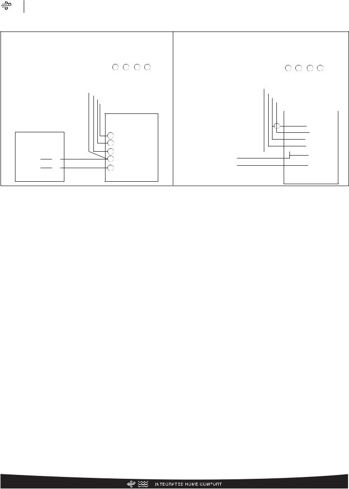
Control Wiring
FIGURE 2
CONTROL WIRING FOR GAS OR OIL FURNACE
|
|
|
|
|
|
|
|
|
|
|
|
|
|
|
|
|
|
TYPICAL THERMOSTAT |
|||||
FOR TYPICAL GAS OR OIL HEAT |
|
|
|
|
|
SUBBASE |
|||||
|
|
|
|
|
|
Y |
G W R |
||||
|
|
|
|
|
|
|
|
|
|
|
|
BR – BROWN WIRE |
|
|
|
|
|
||||||
YL – YELLOW WIRE |
|
|
|
|
|
||||||
X – WIRE CONNECTION |
|
|
|
|
|
||||||
|
|
|
|
|
|
|
|
|
|
|
|
|
|
|
|
|
|
|
|
|
|
|
|
|
|
|
|
|
|
|
|
|
|
|
|
|
|
|
|
|
|
|
|
|
|
|
|
TYPICAL GAS OR
OIL FURNACE
TYPICAL CONDENSING |
|
R |
UNIT |
|
W |
|
|
|
|
|
G |
YL |
X |
Y |
|
||
BR |
X |
C |
|
*IF MAXIMUM OUTLET TEMPERATURE RISE IS DESIRED, IT IS RECOMMENDED THAT W1 (W/BK) AND W2 (W/BL) BE JUMPERED TOGETHER.
|
|
|
|
|
|
|
|
|
|
|
|
|
|
FOR TYPICAL ELECTRIC HEAT |
|
|
|
|
|
TYPICAL THERMOSTAT |
|
||||||
|
|
|
|
|
|
|
SUBBASE |
|
|||||
|
|
|
|
|
|
|
Y |
G W R |
|
||||
BR – BROWN WIRE |
|
|
|
|
|
|
|||||||
R – RED WIRE |
|
|
|
|
|
|
|
|
|
|
|||
|
|
|
|
|
|
|
|
|
|
||||
YL – YELLOW WIRE |
|
|
|
|
|
|
|
|
|||||
W/BK – WHITE WIRE WITH BLACK STRIPE |
|
|
|
|
|
|
|
||||||
G/BK – GREEN WIRE WITH BLACK STRIPE |
|
|
|
|
|
|
|||||||
|
|
|
|
|
|
||||||||
PU – PURPLE WIRE (NOT USED) |
|
|
|
|
|
||||||||
X – WIRE CONNECTION |
|
|
|
|
|
|
|
||||||
|
|
|
|
|
|
|
|||||||
TYPICAL ELECTRIC HEAT
LOW VOLTAGE JUNCTION BOX
|
|
|
|
* • |
|
|
X |
W/BL |
|
|||||||||||
|
|
|
|
|
|
|
|
|||||||||||||
|
|
|
|
|
|
X |
|
|
R |
|
|
|
|
|
|
|
||||
TYPICAL CONDENSING |
|
|
|
|
|
|
|
|
|
|
|
|
|
|||||||
|
UNIT |
|
|
|
|
X |
W/BK |
|
||||||||||||
|
|
|
|
|
|
|||||||||||||||
|
|
|
|
|
|
|
|
X |
G/BK |
|
|
|
||||||||
|
|
|
|
|
|
|
|
|
|
|
||||||||||
|
|
|
|
|
|
|
|
|
|
|
|
|
YL |
|
|
|
|
|
|
|
|
|
YL |
|
X |
|
X |
|
|
|
|||||||||||
|
|
|
|
|
|
|
||||||||||||||
|
|
BR |
|
|
X |
|
BR |
|
|
|
|
|||||||||
|
|
|
X |
|
|
|
||||||||||||||
|
|
|
|
|
|
|||||||||||||||
|
|
|
|
|
|
|
|
|
|
|
|
|
PU |
|
|
|||||
|
|
|
|
|
|
|
|
|
|
|
|
|
|
|
||||||
|
|
|
|
|
|
|
|
|
|
|
|
|
|
|
|
|
|
|
|
|
Application Guidelines
1.Intended for outdoor installation with free air inlet and outlet. Outdoor fan external static pressure available is less than 0.01 -in. wc.
2.Minimum outdoor operation air temperature for cooling mode without low-ambient operation accessory is 55°F (12.8°C).
3.Maximum outdoor operating air temperature is 125°F (51.7°C).
4.For reliable operation, unit should be level in all horizontal planes.
5.Use only copper wire for electric connections at unit. Aluminum and clad aluminum are not acceptable for the type of connector provided.
6.Do not apply capillary tube indoor coils to these units.
7.Factory – supplied filter drier must be installed.
12
13
Refrigerant Line Size Information
|
|
|
|
|
|
|
|
|
|
|
|
|
|
Liquid Line Selection Chart |
|
|
|
|
|
|
|
|
|
||||
|
R-410A System |
Liquid Line Size |
Liquid Line Size |
|
|
|
|
|
|
|
|
Elevation (Above or Below) Indoor Coil |
|
|
|
|
|
|
|
|
|||||||
|
|
|
|
|
|
|
|
|
|
Total Equivalent Length - Feet [m] |
|
|
|
|
|
|
|
|
|||||||||
|
Connection Size |
|
|
|
|
|
|
|
|
|
|
|
|
|
|
|
|
|
|||||||||
|
Capacity Model |
(Inch O.D.) [mm] |
|
|
|
|
|
|
|
|
|
|
|
|
|
|
|
|
|
||||||||
|
(Inch I.D.) [mm] |
25 [7.62] |
50 |
[15.24] |
75 [22.86] |
100 |
[30.48] |
125 [45.72] |
150 [45.72] |
175 [53.34] |
200 [60.96] |
225 [68.58] |
250 [76.20] |
275 [83.82] |
300 [91.44] |
||||||||||||
|
|
|
|
|
|
|
|
|
|
|
|
|
|
|
|
|
|
|
|
|
|
|
|
|
|||
|
|
|
|
|
|
|
|
|
|
|
|
|
Maximum Vertical Separation – Feet [m] |
|
|
|
|
|
|
|
|
||||||
|
|
|
|
|
|
|
|
|
|
|
|
|
|
|
|
|
|
|
|
|
|
|
|
|
|
|
|
|
|
|
1/4 |
[6.35] |
25 [7.62] |
50 |
[15.24] |
65 [19.81] |
50 |
[15.24] |
35 |
[10.67] |
20 |
[6.1] |
|
N/R |
|
N/R |
|
N/R |
|
N/R |
|
N/R |
|
N/R |
|
|
|
|
5/16 |
[7.94] |
25 [7.62] |
50 |
[15.24] |
75 [22.86] |
95 |
[28.96] |
90 |
[27.43] |
85 |
[25.91] |
80 |
[24.38] |
75 |
[22.86] |
75 |
[22.86] |
70 |
[21.34] |
65 |
[19.81] |
60 |
[18.29] |
|
|
18 |
3/8" [9.53] |
3/8 |
[9.53] |
25 [7.62] |
50 |
[15.24] |
75 [22.86] |
100 |
[30.48] |
100 |
[30.48] |
100 |
[30.48] |
100 |
[30.48] |
100 |
[30.48] |
95 |
[28.96] |
95 |
[28.96] |
95 |
[28.96] |
90 |
[27.43] |
|
|
|
|
7/16 [11.12] |
25 [7.62] |
50 |
[15.24] |
75 [22.86] |
100 |
[30.48] |
105 |
[32] |
105 |
[32] |
105 |
[32] |
105 |
[32] |
105 |
[32] |
105 |
[32] |
100 |
[30.48] |
100 |
[30.48] |
||
|
|
|
1/2 [12.71] |
25 [7.62] |
50 |
[15.24] |
75 [22.86] |
100 |
[30.48] |
105 |
[32] |
105 |
[32] |
105 |
[32] |
105 |
[32] |
105 |
[32] |
105 |
[32] |
105 |
[32] |
105 |
[32] |
||
|
|
|
1/4 |
[6.35] |
25 [7.62] |
50 |
[15.24] |
30 |
[9.14] |
|
N/R |
|
N/R |
|
N/R |
|
N/R |
|
N/R |
|
N/R |
|
N/R |
|
N/R |
|
N/R |
|
|
|
|
|
|
|
|
|
|
|
|
|
|
|
|
|
|
|
|
|
|
|
|
|
|
|
|
|
|
|
5/16 |
[7.94] |
25 [7.62] |
50 |
[15.24] |
75 [22.86] |
80 |
[24.38] |
75 |
[22.86] |
70 |
[21.34] |
60 |
[18.29] |
55 |
[16.76] |
50 |
[15.24] |
40 |
[12.19] |
35 |
[10.67] |
30 |
[9.14] |
|
|
24 |
3/8" [9.53] |
3/8 |
[9.53] |
25 [7.62] |
50 |
[15.24] |
75 [22.86] |
100 |
[30.48] |
95 |
[28.96] |
95 |
[28.96] |
90 |
[27.43] |
90 |
[27.43] |
85 |
[25.91] |
85 |
[25.91] |
80 |
[24.38] |
80 |
[24.38] |
|
|
|
|
7/16 [11.12] |
25 [7.62] |
50 |
[15.24] |
75 [22.86] |
100 |
[30.48] |
100 |
[30.48] |
100 |
[30.48] |
100 |
[30.48] |
100 |
[30.48] |
100 |
[30.48] |
95 |
[28.96] |
95 |
[28.96] |
95 |
[28.96] |
||
|
|
|
1/2 [12.71] |
25 [7.62] |
50 |
[15.24] |
75 [22.86] |
100 |
[30.48] |
105 |
[32] |
105 |
[32] |
105 |
[32] |
105 |
[32] |
105 |
[32] |
100 |
[30.48] |
100 |
[30.48] |
100 |
[30.48] |
||
|
|
|
1/4 |
[6.35] |
25 [7.62] |
25 |
[7.62] |
|
N/R |
|
N/R |
|
N/R |
|
N/R |
|
N/R |
|
N/R |
|
N/R |
|
N/R |
|
N/R |
|
N/R |
|
|
|
|
|
|
|
|
|
|
|
|
|
|
|
|
|
|
|
|
|
|
|
|
|
|
|
|
|
|
|
5/16 |
[7.94] |
25 [7.62] |
50 |
[15.24] |
75 [22.86] |
65 |
[19.81] |
55 |
[16.76] |
45 |
[13.72] |
35 |
[10.67] |
25 |
[7.62] |
15 |
[4.57] |
5 |
[1.52] |
|
N/R |
|
N/R |
|
|
30 |
3/8" [9.53] |
3/8 |
[9.53] |
25 [7.62] |
50 |
[15.24] |
75 [22.86] |
90 |
[27.43] |
90 |
[27.43] |
85 |
[25.91] |
80 |
[24.38] |
80 |
[24.38] |
75 |
[22.86] |
70 |
[21.34] |
70 |
[21.34] |
65 |
[19.81] |
|
|
|
|
7/16 [11.12] |
25 [7.62] |
50 |
[15.24] |
75 [22.86] |
100 |
[30.48] |
100 |
[30.48] |
95 |
[28.96] |
95 |
[28.96] |
95 |
[28.96] |
95 |
[28.96] |
90 |
[27.43] |
90 |
[27.43] |
90 |
[27.43] |
||
|
|
|
1/2 [12.71] |
25 [7.62] |
50 |
[15.24] |
75 [22.86] |
100 |
[30.48] |
100 |
[30.48] |
100 |
[30.48] |
100 |
[30.48] |
100 |
[30.48] |
100 |
[30.48] |
100 |
[30.48] |
100 |
[30.48] |
95 |
[28.96] |
||
|
|
|
1/4 |
[6.35] |
25 [7.62] |
10 |
[3.05] |
|
N/R |
|
N/R |
|
N/R |
|
N/R |
|
N/R |
|
N/R |
|
N/R |
|
N/R |
|
N/R |
|
N/R |
|
|
|
|
|
|
|
|
|
|
|
|
|
|
|
|
|
|
|
|
|
|
|
|
|
|
|
|
|
|
|
5/16 |
[7.94] |
25 [7.62] |
50 |
[15.24] |
65 [19.81] |
55 |
[16.76] |
45 |
[13.72] |
30 |
[9.14] |
20 |
[6.1] |
10 |
[3.05] |
|
N/R |
|
N/R |
|
N/R |
|
N/R |
|
|
36 |
3/8" [9.53] |
3/8 |
[9.53] |
25 [7.62] |
50 |
[15.24] |
75 [22.86] |
85 |
[25.91] |
80 |
[24.38] |
80 |
[24.38] |
75 |
[22.86] |
70 |
[21.34] |
65 |
[19.81] |
60 |
[18.29] |
55 |
[16.76] |
55 |
[16.76] |
|
|
|
|
7/16 [11.12] |
25 [7.62] |
50 |
[15.24] |
75 [22.86] |
95 |
[28.96] |
95 |
[28.96] |
90 |
[27.43] |
90 |
[27.43] |
90 |
[27.43] |
85 |
[25.91] |
85 |
[25.91] |
85 |
[25.91] |
80 |
[24.38] |
||
|
|
|
1/2 [12.71] |
25 [7.62] |
50 |
[15.24] |
75 [22.86] |
100 |
[30.48] |
100 |
[30.48] |
95 |
[28.96] |
95 |
[28.96] |
95 |
[28.96] |
95 |
[28.96] |
95 |
[28.96] |
95 |
[28.96] |
90 |
[27.43] |
||
|
|
|
1/4 |
[6.35] |
15 [4.57] |
|
N/R |
|
N/R |
|
N/R |
|
N/R |
|
N/R |
|
N/R |
|
N/R |
|
N/R |
|
N/R |
|
N/R |
|
N/R |
|
|
|
|
|
|
|
|
|
|
|
|
|
|
|
|
|
|
|
|
|
|
|
|
|
|
|
|
|
|
|
5/16 |
[7.94] |
25 [7.62] |
50 |
[15.24] |
35 [10.67] |
15 |
[4.57] |
|
N/R |
|
N/R |
|
N/R |
|
N/R |
|
N/R |
|
N/R |
|
N/R |
|
N/R |
|
|
|
|
|
|
|
|
|
|
|
|
|
|
|
|
|
|
|
|
|
|
|
|
|
|
|
|
|
|
42 |
3/8" [9.53] |
3/8 |
[9.53] |
25 [7.62] |
50 |
[15.24] |
70 [21.34] |
65 |
[19.81] |
60 |
[18.29] |
50 |
[15.24] |
45 |
[13.72] |
40 |
[12.19] |
35 |
[10.67] |
25 |
[7.62] |
20 |
[6.1] |
15 |
[4.57] |
|
|
|
|
7/16 [11.12] |
25 [7.62] |
50 |
[15.24] |
75 [22.86] |
80 |
[24.38] |
75 |
[22.86] |
75 |
[22.86] |
70 |
[21.34] |
70 |
[21.34] |
65 |
[19.81] |
65 |
[19.81] |
60 |
[18.29] |
55 |
[16.76] |
||
|
|
|
1/2 [12.71] |
25 [7.62] |
50 |
[15.24] |
75 [22.86] |
85 |
[25.91] |
85 |
[25.91] |
80 |
[24.38] |
80 |
[24.38] |
80 |
[24.38] |
80 |
[24.38] |
75 |
[22.86] |
75 |
[22.86] |
75 |
[22.86] |
||
|
|
|
1/4 |
[6.35] |
N/R |
|
N/R |
|
N/R |
|
N/R |
|
N/R |
|
N/R |
|
N/R |
|
N/R |
|
N/R |
|
N/R |
|
N/R |
|
N/R |
|
|
|
5/16 |
[7.94] |
25 [7.62] |
40 |
[12.19] |
20 |
[6.1] |
|
N/R |
|
N/R |
|
N/R |
|
N/R |
|
N/R |
|
N/R |
|
N/R |
|
N/R |
|
N/R |
|
|
|
|
|
|
|
|
|
|
|
|
|
|
|
|
|
|
|
|
|
|
|
|
|
|
|
|
|
48 |
3/8" [9.53] |
3/8 |
[9.53] |
25 [7.62] |
50 |
[15.24] |
65 [19.81] |
55 |
[16.76] |
50 |
[15.24] |
40 |
[12.19] |
35 |
[10.67] |
25 |
[7.62] |
20 |
[6.1] |
10 |
[3.05] |
|
N/R |
|
N/R |
|
|
|
|
7/16 [11.12] |
25 [7.62] |
50 |
[15.24] |
75 [22.86] |
75 |
[22.86] |
70 |
[21.34] |
65 |
[19.81] |
65 |
[19.81] |
60 |
[18.29] |
55 |
[16.76] |
55 |
[16.76] |
50 |
[15.24] |
50 |
[15.24] |
||
|
|
|
1/2 [12.71] |
25 [7.62] |
50 |
[15.24] |
75 [22.86] |
80 |
[24.38] |
80 |
[24.38] |
75 |
[22.86] |
75 |
[22.86] |
75 |
[22.86] |
70 |
[21.34] |
70 |
[21.34] |
70 |
[21.34] |
65 |
[19.81] |
||
|
|
|
1/4 |
[6.35] |
N/R |
|
N/R |
|
N/R |
|
N/R |
|
N/R |
|
N/R |
|
N/R |
|
N/R |
|
N/R |
|
N/R |
|
N/R |
|
N/R |
|
|
|
|
|
|
|
|
|
|
|
|
|
|
|
|
|
|
|
|
|
|
|
|
|
|
|
|
|
|
|
5/16 |
[7.94] |
25 [7.62] |
5 |
[1.52] |
|
N/R |
|
N/R |
|
N/R |
|
N/R |
|
N/R |
|
N/R |
|
N/R |
|
N/R |
|
N/R |
|
N/R |
|
|
|
|
|
|
|
|
|
|
|
|
|
|
|
|
|
|
|
|
|
|
|
|
|
|
|
|
|
60 |
3/8" [9.53] |
3/8 |
[9.53] |
25 [7.62] |
45 |
[13.72] |
35 [10.67] |
25 |
[7.62] |
15 |
[4.57] |
|
N/R |
|
N/R |
|
N/R |
|
N/R |
|
N/R |
|
N/R |
|
N/R |
|
|
|
|
7/16 [11.12] |
25 [7.62] |
50 |
[15.24] |
55 [16.76] |
50 |
[15.24] |
45 |
[13.72] |
40 |
[12.19] |
35 |
[10.67] |
30 |
[9.14] |
30 |
[9.14] |
25 |
[7.62] |
20 |
[6.1] |
15 |
[4.57] |
||
|
|
|
1/2 [12.71] |
25 [7.62] |
50 |
[15.24] |
60 [18.29] |
60 |
[18.29] |
55 |
[16.76] |
55 |
[16.76] |
55 |
[16.76] |
50 |
[15.24] |
50 |
[15.24] |
45 |
[13.72] |
45 |
[13.72] |
40 |
[12.19] |
||
|
|
|
|
|
|
|
|
|
|
|
|
|
|
|
|
|
|
|
|
|
|
|
|
|
|
|
|
NOTES: |
|
|
|
|
|
|
|
|
|
|
|
|
|
|
|
|
|
|
|
[ |
] Designates Metric Conversions |
||||||
N/R = Application not recommended.
Grey =This application is acceptable, but the long line guidelines must be followed. Reference Long Line Set section in the I&O
|
Air |
|
|
Series RA14 |
Line Refrigerant |
|
Information Size |
Refrigerant Line Size Information (con’t.)
14 |
|
|
|
|
|
|
|
|
|
Vapor Line Selection Chart |
|
|
|
|
||
|
|
|
|
|
|
|
|
|
Capacity Multiplier Table |
|
|
|
|
|||
|
|
Vapor Line |
|
|
|
|
|
|
|
|
|
|
|
|||
|
R-410A System |
Vapor Line Size |
|
|
|
|
|
Total Equivalent Length - Feet [m] |
|
|
|
|
||||
|
Connection Size |
|
|
|
|
|
|
|
|
|
||||||
|
Capacity Model |
(Inch O.D.) [mm] |
|
|
|
|
|
|
|
|
|
|
|
|
||
|
|
(Inch I.D.) [mm] |
|
|
25 [7.62] |
50 [15.24] |
75 [22.86] |
100 [30.48] |
125 [45.72] |
150 [45.72] |
175 [53.34] |
200 [60.96] |
225 [68.58] |
250 [76.20] |
275 [83.82] |
300 [91.44] |
|
|
|
|
|
|
|
|
|
|
|
|
|
|
|
|
|
|
|
|
5/8 [15.88] |
1.00 |
0.99 |
0.99 |
0.98 |
0.98 |
0.98 |
0.97 |
0.97 |
0.96 |
0.96 |
0.96 |
0.95 |
|
|
|
|
|
|
|
|
|
|
|
|
|
|
|
|
|
|
|
|
|
3/4 [19.05] |
1.00 |
1.00 |
1.00 |
1.00 |
1.00 |
0.99 |
0.99 |
0.99 |
0.99 |
0.99 |
0.99 |
0.99 |
|
|
|
|
|
|
|
|
|
|
|
|
|
|
|
|
|
|
|
18 |
3/4" [19.06] |
7/8 [22.23] |
N/R |
N/R |
N/R |
N/R |
N/R |
N/R |
N/R |
N/R |
N/R |
N/R |
N/R |
N/R |
|
|
|
|
|
|
|
|
|
|
|
|
|
|
|
|
|
|
|
|
|
1 |
[25.4] |
N/R |
N/R |
N/R |
N/R |
N/R |
N/R |
N/R |
N/R |
N/R |
N/R |
N/R |
N/R |
|
|
|
|
|
|
|
|
|
|
|
|
|
|
|
|
|
|
|
|
1-1/8 [28.58] |
N/R |
N/R |
N/R |
N/R |
N/R |
N/R |
N/R |
N/R |
N/R |
N/R |
N/R |
N/R |
|
|
|
|
|
|
|
|
|
|
|
|
|
|
|
|
|
|
|
|
|
5/8 [15.88] |
0.99 |
1.00 |
0.99 |
0.98 |
0.97 |
0.97 |
0.96 |
0.95 |
0.94 |
0.94 |
0.93 |
0.94 |
|
|
|
|
3/4 [19.05] |
1.00 |
1.01 |
1.01 |
1.01 |
1.01 |
1.00 |
1.00 |
0.99 |
0.99 |
0.99 |
0.99 |
0.99 |
|
|
|
|
|
|
|
|
|
|
|
|
|
|
|
|
|
|
|
24 |
3/4" [19.06] |
7/8 [22.23] |
1.00 |
1.00 |
1.01 |
1.00 |
1.02 |
1.01 |
1.01 |
1.01 |
1.01 |
1.01 |
1.01 |
1.00 |
|
|
|
|
|
|
|
|
|
|
|
|
|
|
|
|
|
|
|
|
|
1 |
[25.4] |
N/R |
N/R |
N/R |
N/R |
N/R |
N/R |
N/R |
N/R |
N/R |
N/R |
N/R |
N/R |
|
|
|
|
|
|
|
|
|
|
|
|
|
|
|
|
|
|
|
|
1-1/8 [28.58] |
N/R |
N/R |
N/R |
N/R |
N/R |
N/R |
N/R |
N/R |
N/R |
N/R |
N/R |
N/R |
|
|
|
|
|
|
|
|
|
|
|
|
|
|
|
|
|
|
|
|
|
5/8 [15.88] |
1.00 |
0.98 |
0.97 |
0.97 |
0.95 |
0.95 |
0.94 |
0.93 |
0.93 |
0.92 |
0.92 |
0.91 |
|
|
|
|
|
|
|
|
|
|
|
|
|
|
|
|
|
|
|
|
|
3/4 [19.05] |
1.00 |
1.00 |
0.99 |
0.99 |
0.99 |
0.98 |
0.98 |
0.98 |
0.97 |
0.97 |
0.97 |
0.96 |
|
|
30 |
3/4" [19.06] |
7/8 [22.23] |
1.01 |
1.00 |
1.00 |
1.00 |
1.00 |
0.99 |
0.99 |
0.99 |
1.00 |
1.00 |
1.00 |
1.00 |
|
|
|
|
|
|
|
|
|
|
|
|
|
|
|
|
|
|
|
|
|
1 |
[25.4] |
N/R |
N/R |
N/R |
N/R |
N/R |
N/R |
N/R |
N/R |
N/R |
N/R |
N/R |
N/R |
|
|
|
1-1/8 [28.58] |
N/R |
N/R |
N/R |
N/R |
N/R |
N/R |
N/R |
N/R |
N/R |
N/R |
N/R |
N/R |
|
|
|
|
|
|
|
|
|
|
|
|
|
|
|
|
|
|
|
|
|
5/8 [15.88] |
0.99 |
0.98 |
0.97 |
0.96 |
0.95 |
0.93 |
0.93 |
0.91 |
0.9 |
0.9 |
0.89 |
0.88 |
|
|
|
|
|
|
|
|
|
|
|
|
|
|
|
|
|
|
|
|
|
3/4 [19.05] |
1.00 |
1.00 |
0.99 |
0.99 |
0.98 |
0.99 |
0.99 |
0.97 |
0.98 |
0.97 |
0.96 |
0.96 |
|
|
|
|
|
|
|
|
|
|
|
|
|
|
|
|
|
|
|
36 |
3/4" [19.06] |
7/8 [22.23] |
1.01 |
1.01 |
1.00 |
1.00 |
1.00 |
0.99 |
0.99 |
0.99 |
0.99 |
0.99 |
0.99 |
0.98 |
|
|
|
|
|
|
|
|
|
|
|
|
|
|
|
|
|
|
|
|
|
1 |
[25.4] |
1.01 |
1.01 |
1.01 |
1.00 |
1.00 |
1.00 |
1.01 |
1.00 |
1.00 |
1.00 |
1.00 |
1.00 |
|
|
|
|
|
|
|
|
|
|
|
|
|
|
|
|
|
|
|
|
1-1/8 [28.58] |
N/R |
N/R |
N/R |
N/R |
N/R |
N/R |
N/R |
N/R |
N/R |
N/R |
N/R |
N/R |
|
|
|
|
5/8 [15.88] |
1.00 |
0.97 |
0.95 |
0.93 |
0.92 |
0.91 |
0.9 |
0.89 |
0.87 |
0.85 |
0.85 |
0.84 |
|
|
|
|
3/4 [19.05] |
1.00 |
1.00 |
0.99 |
0.99 |
0.97 |
0.97 |
0.97 |
0.95 |
0.95 |
0.95 |
0.94 |
0.93 |
|
|
|
|
|
|
|
|
|
|
|
|
|
|
|
|
|
|
|
42 |
7/8" [22.23] |
7/8 [22.23] |
1.00 |
1.00 |
1.01 |
1.00 |
1.00 |
0.99 |
0.99 |
0.99 |
0.99 |
0.98 |
0.98 |
0.98 |
|
|
|
|
|
|
|
|
|
|
|
|
|
|
|
|
|
|
|
|
|
1 |
[25.4] |
1.01 |
1.00 |
0.99 |
1.00 |
1.00 |
1.01 |
1.01 |
1.00 |
1.01 |
1.00 |
0.99 |
0.99 |
|
|
|
|
|
|
|
|
|
|
|
|
|
|
|
|
|
|
|
|
1-1/8 [28.58] |
N/R |
N/R |
N/R |
N/R |
N/R |
N/R |
N/R |
N/R |
N/R |
N/R |
N/R |
N/R |
|
|
|
|
|
|
|
|
|
|
|
|
|
|
|
|
|
|
|
|
|
5/8 [15.88] |
0.98 |
0.95 |
0.93 |
0.92 |
0.9 |
0.88 |
0.86 |
0.85 |
0.84 |
0.82 |
N/R |
N/R |
|
|
|
|
|
|
|
|
|
|
|
|
|
|
|
|
|
|
|
|
|
3/4 [19.05] |
0.99 |
0.98 |
0.97 |
0.96 |
0.96 |
0.95 |
0.94 |
0.93 |
0.92 |
0.92 |
N/R |
N/R |
|
|
48 |
7/8" [22.23] |
7/8 [22.23] |
1.00 |
1.00 |
0.98 |
0.98 |
0.97 |
0.97 |
0.97 |
0.97 |
0.96 |
0.96 |
N/R |
N/R |
|
|
|
|
|
|
|
|
|
|
|
|
|
|
|
|
|
|
|
|
|
1 |
[25.4] |
1.00 |
1.00 |
0.99 |
0.99 |
0.99 |
0.98 |
0.98 |
0.98 |
0.98 |
0.98 |
N/R |
N/R |
|
|
|
1-1/8 [28.58] |
1.00 |
1.00 |
0.99 |
0.99 |
0.99 |
0.99 |
0.99 |
0.99 |
0.99 |
0.99 |
N/R |
N/R |
|
|
|
|
|
|
|
|
|
|
|
|
|
|
|
|
|
|
|
|
|
5/8 [15.88] |
0.97 |
0.94 |
0.91 |
0.89 |
0.87 |
N/R |
N/R |
N/R |
N/R |
N/R |
N/R |
N/R |
|
|
|
|
|
|
|
|
|
|
|
|
|
|
|
|
|
|
|
|
|
3/4 [19.05] |
0.99 |
0.98 |
0.96 |
0.95 |
0.94 |
N/R |
N/R |
N/R |
N/R |
N/R |
N/R |
N/R |
|
|
|
|
|
|
|
|
|
|
|
|
|
|
|
|
|
|
|
60 |
7/8" [22.23] |
7/8 [22.23] |
1.00 |
0.99 |
0.99 |
0.98 |
0.98 |
N/R |
N/R |
N/R |
N/R |
N/R |
N/R |
N/R |
|
|
|
|
1 |
[25.4] |
1.00 |
1.00 |
1.00 |
1.00 |
0.99 |
N/R |
N/R |
N/R |
N/R |
N/R |
N/R |
N/R |
|
|
|
|
|
|
|
|
|
|
|
|
|
|
|
|
|
|
|
|
1-1/8 [28.58] |
1.00 |
1.00 |
1.00 |
1.00 |
1.00 |
N/R |
N/R |
N/R |
N/R |
N/R |
N/R |
N/R |
|
NOTES: |
[ ] Designates Metric Conversions |
N/R = Application not recommended. |
|
All calculations assume a 3/8" liquid line |
|
|
Air |
|
|
Series RA14 |
Line Refrigerant |
|
Information Size |
 Loading...