


Use & Care Manual
With Installation Instructions for the Installer
Electric Residential Heat Pump
Water Heaters
Residential 50 Gallon - HB Series
The purpose of this manual is twofold: one, to provide the installer with the basic directions and recommendations for the proper installation and adjustment of the water heater; and two, for the owner– operator, to explain the features, operation, safety precautions, maintenance and troubleshooting of the water heater. This manual also includes a parts list.
It is imperative that all persons who are expected to install, operate or adjust this water heater read the instructions carefully so they may understand how to perform these operations. If you do not understand these instructions or any terms within it, seek professional advice.
Any questions regarding the operation, maintenance, service or warranty of this water heater should be directed to the seller from whom it was purchased. If additional information is required, refer to the section on “If you need service.”
DO NOT destroy this manual. Please read carefully and keep in a safe place for future reference.
Recognize this symbol as an ! indication of Important Safety
Information!
California Proposition 65
! Warning: This product contains chemicals known to the State of California to cause cancer, birth defects or other reproductive harm.
|
92-103234-12 |
© 2013 Rheem Manufacturing Co. |
AP16244-1 (06/13) |
Printed in USA
Safety Information
Safety Precautions. . . . 3-4
Installation Instructions
Location. . . . . . . . . 5 Water Connections . . . . . 6 Condensate Drain . . . . . 6 Relief Valve. . . . . . . . 7 Electrical Connections. . . . 8-9 Pipe Insulation. . . . . . 10 Installation Checklist.. . . 11
Operating Instructions
Safety Controls . . . . . . 12 Water Temperature . . . . .12
Basic Water Heater Operation .
. . . . . . . . . . . . . . . . . . . . . .13-14
Care and Cleaning
Draining. . . . . . . . . 15
Maintenance. . . . . . 15
Extended Shut-Down. . . 16
Troubleshooting Tips
Before You Call
For Service.. . . . . . . 17
Customer Service |
|
Parts List. . . . . . . . |
20 |
Wiring Diagram . . . . . |
22 |
If You Need |
|
Service. . . . . . . . . |
24 |
FOR YOUR RECORDS
Write the model and serial numbers here:
#
#
You can find them on a label on the appliance. Staple sales slip or cancelled check here.
Proof of the original purchase date is needed to obtain service under the warranty.
READ THIS MANUAL
Inside you will find many helpful hints on how to use and maintain your water heater properly. Just a little preventive care on your part can save you a great deal of time and money over the life of your water heater.
You’ll find many answers to common problems in the Before You Call For Service section. If you review our chart of Troubleshooting Tips first, you may not need to call for service at all.
READ THE SAFETY INFORMATION
Your safety and the safety of others are very important. There are many important safety messages in this manual and on your appliance. Always read and obey all safety messages.
This is the safety alert symbol. Recognize this ! symbol as an indication of Important Safety
Information!
This symbol alerts you to potential hazards that can kill or hurt you and others.
All safety messages will follow the safety alert symbol and either the word “DANGER”, “WARNING”, “CAUTION” or “NOTICE”.
These words mean: |
|
|
! |
DANGER |
An imminently hazardous situation |
|
|
that will result in death or serious |
|
WARNING |
injury. |
! |
A potentially hazardous situation that |
|
|
|
could result in death or serious |
|
CAUTION |
injury and/or damage to property. |
! |
A potentially hazardous situation that |
|
|
|
may result in minor or moderate |
|
|
injury. |
NOTICE: |
Attention is called to observe a |
|
|
|
specified procedure or maintain a |
specific condition.

IMPORTANT SAFETY INFORMATION. READ ALL INSTRUCTIONS BEFORE USING.
 DANGER!
WATER TEMPERATURE SETTING
Safety and energy conservation are factors to be considered when selecting the water temperature setting of water heater. Water temperatures above 125°F can cause severe burns or death from scalding. Be sure to read and follow the warnings outlined on the label pictured below. This label is also located on the water heater near the thermistor access panel.
! D A N G E R
HOT
BURN
Water temperature over 125°F can cause severe burns instantly or death from scalds.
Children, disabled and elderly are at highest risk of being scalded.
See instruction manual before setting temperature at water heater.
Feel water before bathing or showering.
Temperature limiting valves are available, see manual.
Time/Temperature Relationship in Scalds
Temperature |
Time To Produce a Serious Burn |
120°F (49°C) |
More than 5 minutes |
125°F (52°C) |
1½ to 2 minutes |
130°F (54°C) |
About 30 seconds |
135°F (57°C) |
About 10 seconds |
140°F (60°C) |
Less than 5 seconds |
145°F (63°C) |
Less than 3 seconds |
150°F (65°C) |
About 1½ seconds |
155°F (68°C) |
About 1 second |
|
|
Table courtesy of Shriners Burn Institute
The chart shown above may be used as a guide in determining the proper water temperature for your home.
! DANGER: Households with small children, disabled, or elderly persons may require a 120°F or lower thermostat setting to prevent contact with “HOT” water.
The temperature of the water in the heater is regulated by the water heater interface control. To comply with safety regulations the temperature was set at 120°F before the water heater was shipped from the factory.
The illustration below shows the water temperature setting.
Refer to the Operating Instructions in this manual for detailed instructions in how to adjust the water temperature.
NOTICE: Mixing valves are available for reducing point of use water temperature by mixing hot and cold water in branch water lines. Contact a licensed plumber or the local plumbing authority for further information.
!DANGER: Hotter water increases the potential for Hot Water SCALDS.
3
IMPORTANT SAFETY INFORMATION. READ ALL INSTRUCTIONS BEFORE USING.
 WARNING!
For your safety, the information in this manual must be followed to minimize the risk of fire or explosion, electric shock, or to prevent property damage, personal injury, or loss of life.
Be sure to read and understand the entire Use and Care Manual before attempting to install or operate this water heater. It may save you time and cost. Pay particular attention to the Safety Instructions. Failure to follow these warnings could result in
serious bodily injury or death. Should you have problems understanding the instructions in this manual, or have any questions, STOP, and get help from a qualified service technician, or the local electric utility.
FOR INSTALLATIONS IN THE STATE OF CALIFORNIA
California Law requires that residential water heaters must be braced, anchored or strapped to resist falling or horizontal displacement due to earthquake motions. For residential water heaters up to 52-gallon capacity, a brochure with generic earthquake bracing instructions can be obtained from: Office of the State Architect, 1102 Q Street, Suite 5100, Sacramento, CA 95814 or you may call 916-445-8100 or ask a water heater dealer.
However, applicable local codes shall govern installation. For residential water heaters of a capacity greater than 52 gallons, consult the local building jurisdiction for acceptable bracing procedures.
 CAUTION: DO NOT “crush” or otherwise impair the removal of the “plastic” front (side) panel.
SAFETY PRECAUTIONS
Have the installer show you the location of the circuit breaker and how to shut it off if necessary. Turn off the circuit breaker if the water heater has been subjected to overheating, fire, flood, physical damage or if the ECO (temperature limiting control) fails to shut off.
●Read this manual entirely before installing or operating the water heater.
●Use this appliance only for its intended purpose as described in this Use and Care Manual.
●Be sure your appliance is properly installed in accordance with local codes and the provided installation instructions.
●DO NOT attempt to repair or replace any part of your water heater unless it is specifically recommended in this manual. All other servicing should be referred to a qualified technician.
 WARNING!
Disconnect all power to unit before starting maintenance. Failure to do so can cause electrical shock resulting in severe personal injury or death.
READ AND FOLLOW THIS SAFETY INFORMATION
 CAREFULLY.
SAVE THESE INSTRUCTIONS
4
Installing the water heater
The location chosen for the water heater must take into consideration the following:
Local Installation Regulations
This water heater must be installed in accordance with these instructions, local codes, utility codes, utility company requirements or, in the absence of local codes, the latest edition of the National Electrical Code. It is available from some local libraries or can be purchased from the National Fire Protection Association,
Batterymarch Park, Quincy, MA 02269 as booklet ANSI/NFPA 70.
Canadian installations should refer to CSA22.1, a copy can be purchased from the Canadian Standards Association, 5050 Spectrum Way, Mississauga,ONT L4W 5N6
NOTICE: Auxiliary catch pan MUST conform to local codes.
Catch Pan Kits are available from the store where the water heater was purchased, or any water heater distributor.
Catch Pan should not obstruct cold inlet or drain valve.
Location
Locate the water heater in a clean dry area as near as practical to the area of greatest heated water demand. Long un-insulated hot water lines can waste energy and water.
Place the water heater in such a manner that the thermistor and element access panels can be removed to permit inspection and servicing such as removal of elements or checking controls.
The water heater and water lines should be protected from freezing temperatures. Do not install the water heater in outdoor, unprotected areas.
Make certain the floor underneath the water heater is strong enough to sufficiently support the weight of the
water heater once it is filled with water.
! CAUTION: The water heater should not be located in an area where leakage of the tank or connections will result in damage to the area adjacent to it or to lower floors of the structure. Where
such areas cannot be avoided, it is recommended that a suitable catch pan, adequately drained, be installed under the water heater.
NOTICE: Installation in a closet or confined space is not allowed.
It is recommended that the Heat Pump Water Heater be installed in a location providing approximately 1,000 cu. ft of unconditioned air. Installation in an enclosed room smaller than 1000 cubic feet (10'x10'x10') is permissible provide that adequate inlet/outlet ventilation is provided, such as louvered door, to allow heat to enter the room. If louvered door is used,
it is recommended that it provide a minimum of two 8"x14" register
openings, one at the top and the other at the bottom of the door, and that these be kept fully opened.
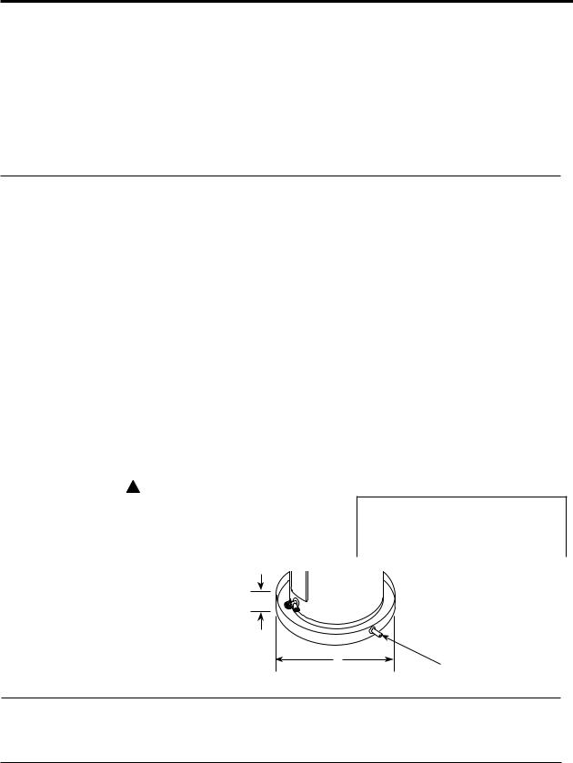
Clearances
Rear |
Top |
2" |
8" Min. |
|
B |
|
A—Diameter of water |
|
|
heater plus 2" min.. |
|
|
B—Maximum 2″ |
A |
To open drain, line |
|
|
should be at least 3/4″ ID |
|
|
and pitched for proper |
|
|
drainage. |
Inspect Shipment
Inspect the water heater for possible damage. Check the markings on the rating plate of the water heater to be certain the power supply corresponds to the water heater requirements. Rating plate is located on front of water heater.
Refrigerant
This heat pump water heater is factory charged with an environmentally friendly, non-chlorinated refrigerant, R410A. This refrigerant has zero ozone depletion potential.
5

Installing the water heater
Thermal Expansion
Determine if a check valve exists in the inlet water line. Check with your local water utility. It may have been installed in the cold water line as a separate back flow preventer, or it may be part of a pressure reducing valve, water meter or water softener. A check valve located in the cold water inlet line can cause what is referred to as a “closed water system”. A cold water inlet line with no check valve or back flow prevention device is referred to as an “open” water system.
As water is heated, it expands in volume and creates an increase in the pressure within the water system. This action is referred to as “thermal expansion”. In an “open” water system, expanding water which exceeds the capacity of the water heater flows back into the city main where the pressure is easily dissipated.
A “closed water system”, however, prevents the expanding water from flowing back into the main supply line, and the result of “thermal expansion” can create a rapid and dangerous pressure increase in the water heater and system piping. This rapid pressure increase can
quickly reach the safety setting of the relief valve, causing it to operate during each heating cycle. Thermal expansion, and the resulting rapid and repeated expansion and contraction of components in the water heater and piping system can cause premature failure of the relief valve, and possibly the heater itself. Replacing the relief valve WILL NOT correct the problem!
The suggested method of controlling thermal expansion is to install an expansion tank in the cold water line between the water heater and the check valve (refer
to the illustration on the next page). The expansion tank is designed with an air cushion built in that compresses as the system pressure increases, thereby relieving the over pressure condition and eliminating the repeated operation of the relief valve. Other methods of controlling thermal expansion are also available. Contact
your installing contractor, water supplier or plumbing inspector for additional information regarding this subject.
Water Supply Connections
Refer to the illustration on the next page for suggested typical installation. The installation of unions or flexible copper connectors is recommended on the hot and cold water connections so that the water heater may be easily disconnected for servicing if necessary. The HOT and COLD water connections are clearly marked and are 3/4″ NPT on all models. Install a shut-off valve in the cold water line near the water heater.
See page 8 on "To Fill The Water Heater".
NOTICE: DO NOT apply heat to the HOT or COLD water connections.
If sweat connections are used, sweat tubing to adapter before fitting adapter to the water connections on heater. Any heat applied to the water supply fittings
will permanently damage the dip tube and/or heat traps.
Condensate Drains for the Heat Pump
Consult local codes or ordinances for specific requirements. Refer to page 7.
IMPORTANT: When making drain fitting connections to the drain tubing, use a thin layer of piping tape or silicone and install hand tight.
IMPORTANT: When making drain fitting connections to the drain tubing, DO NOT overtighten. Overtightening fittings can split pipe connections on the drain pan.
•This unit is equipped with a 3/4" primary condensate connection and a 1/2" overflow connection.
•DO NOT reduce drain line size less
than connection size provided on condensate drain.
•All drain lines must be pitched downward away from the unit a minimum of 1/8" per foot of line to ensure proper drainage.
•Do not connect condensate drain line to a closed or open sewer pipe. DO NOT allow condensate to drain into the water heater drain pan.
•The drain line should be insulated where necessary to prevent sweating and damage due to condensate forming on the outside surface of the line.
6
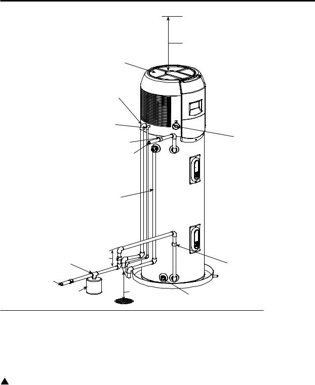
Typical Installation
Ceiling
|
|
8" Minimum clearance above heat |
|
|
pump to allow air circulation |
Heat pump filter |
|
|
Primary condensation (3/4") |
|
|
to open drain or outdoors |
|
|
Secondary condensate tubing |
|
|
(1/2") to open drain or outdoors |
Electrical access cover |
|
|
Union |
|
|
|
|
Hot water outlet |
|
|
to fixtures |
|
|
Temperature and pressure |
|
|
relief valve and discharge |
|
|
line |
|
|
|
Heat trap |
|
Shut off valve |
6" Min |
Union |
Cold water |
|
|
supply |
6" Air gap |
|
Thermal expansion |
Drain valve |
|
tank (if required) |
|
|
A new combination temperature and pressure relief valve, complying with the Standard for Relief Valves and Automatic Gas Shut-Off Devices for Hot Water Supply Systems, ANSI Z21.22/CSA 4.4, is installed in the opening provided. No valve of any type should be installed between the relief valve and the tank.
Local codes shall govern the installation of relief valves.
! WARNING: The pressure rating of the relief valve must not exceed 150 PSI, the maximum working pressure of the water heater as marked on the rating plate.
Relief Valve
The BTUH rating of the relief valve must not be less than the input rating of the water heater as indicated on the rating label located on the front of the heater (1 watt=3.412 BTUH).
Connect the outlet of the relief valve to a suitable open drain so that the discharge water cannot contact live electrical parts or persons and to eliminate potential water damage.
Piping used should be of a type
approved for hot water distribution. The discharge line must be no smaller than the outlet of the valve and must pitch downward from the valve to allow complete drainage (by gravity) of the relief valve and discharge line. The
end of the discharge line should not be threaded or concealed and should be protected from freezing. No valve of any type, restriction or reducer coupling should be installed in the discharge line.
7
Installing the water heater
! WARNING: The tank must be full of water before heater is turned on. The water heater warranty does not cover damage or failure resulting from operation with an empty or partially empty tank.
To Fill the Water Heater
Make certain the drain valve is completely closed.
Open the shut-off valve in the cold water supply line.
Open each hot water faucet slowly to
allow the air to vent from the water heater and piping.
A steady flow of water from the hot water faucet(s) indicates a full water heater.
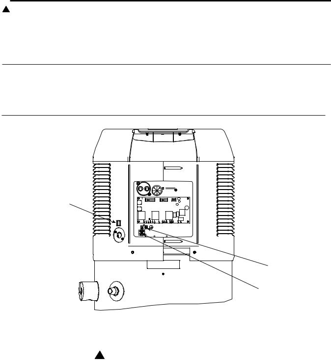
EcoNet™ Communication Port
EcoNet™ communication port is for future integration with home automation, energy management, and demand response systems
EcoNet™ Port
Ground Screw
Electrical Power
Hookup Terminals
Electrical Connections
! WARNING!
Turn off electric power at the fuse box or service panel before making any electrical connections.
Also, the ground connection must be completed before making line voltage connections. Failure to do so can result in electrical shock, severe personal injury or death.
Disconnect all power to unit before starting maintenance. Failure to do so can cause electrical shock resulting in severe personal injury or death
The unit must be grounded. Failure to do so can cause electrical shock resulting in severe personal injury or death.
8
 Loading...