


R96VA
Parts List 17-September-2018
This parts list is current as of the above revision date.
See http://www.rheempartslists.net/92-42800-R96VA.pdf for the current revision.
95% Gas Furnaces - 2 Stage

Table of Contents
Model Explanation . . . . . . . . . . . . . . . . . . . . . . . . . . . . . . . . . . . . . . . . . . . . . . . . . . . . . . . . . . . . . . . . . . . . . . . . . . . . . . . . . . . . . . . . . . . . . . . . . . . . . . . . . . . . . . . . . . . Page 3
Parts Numbers
Panels - Miscellaneous . . . . . . . . . . . . . . . . . . . . . . . . . . . . . . . . . . . . . . . . . . . . . . . . . . . . . . . . . . . . . . . . . . . . . . . . . . . . . . . . . . . . . . . . . . Page 4
Field Conversions . . . . . . . . . . . . . . . . . . . . . . . . . . . . . . . . . . . . . . . . . . . . . . . . . . . . . . . . . . . . . . . . . . . . . . . . . . . . . . . . . . . . . . . . . . . . . . . Page 5
Electrical Group . . . . . . . . . . . . . . . . . . . . . . . . . . . . . . . . . . . . . . . . . . . . . . . . . . . . . . . . . . . . . . . . . . . . . . . . . . . . . . . . . . . . . . . . . . . . . . . . . Page 6
Blower Group. . . . . . . . . . . . . . . . . . . . . . . . . . . . . . . . . . . . . . . . . . . . . . . . . . . . . . . . . . . . . . . . . . . . . . . . . . . . . . . . . . . . . . . . . . . . . . . . . . . . Page 6
Heat Exchanger-Burner Group. . . . . . . . . . . . . . . . . . . . . . . . . . . . . . . . . . . . . . . . . . . . . . . . . . . . . . . . . . . . . . . . . . . . . . . . . . . . . . . . . . . Page 7
Gas Controls . . . . . . . . . . . . . . . . . . . . . . . . . . . . . . . . . . . . . . . . . . . . . . . . . . . . . . . . . . . . . . . . . . . . . . . . . . . . . . . . . . . . . . . . . . . . . . . . . . . . Page 7
Orifice Selection Chart. . . . . . . . . . . . . . . . . . . . . . . . . . . . . . . . . . . . . . . . . . . . . . . . . . . . . . . . . . . . . . . . . . . . . . . . . . . . . . . . . . . . . . . . . . . Page 8
Drawings/Photographs
Exploded View . . . . . . . . . . . . . . . . . . . . . . . . . . . . . . . . . . . . . . . . . . . . . . . . . . . . . . . . . . . . . . . . . . . . . . . . . . . . . . . . . . . . . . . . . . . . . . . . . . Page 9
Cabinet Insulation and Plugs. . . . . . . . . . . . . . . . . . . . . . . . . . . . . . . . . . . . . . . . . . . . . . . . . . . . . . . . . . . . . . . . . . . . . . . . . . . . . . . . . . . . Page 10
Junction Box . . . . . . . . . . . . . . . . . . . . . . . . . . . . . . . . . . . . . . . . . . . . . . . . . . . . . . . . . . . . . . . . . . . . . . . . . . . . . . . . . . . . . . . . . . . . . . . . . . . Page 11
Burner Assembly (1). . . . . . . . . . . . . . . . . . . . . . . . . . . . . . . . . . . . . . . . . . . . . . . . . . . . . . . . . . . . . . . . . . . . . . . . . . . . . . . . . . . . . . . . . . . . Page 12
Burner Assembly (2). . . . . . . . . . . . . . . . . . . . . . . . . . . . . . . . . . . . . . . . . . . . . . . . . . . . . . . . . . . . . . . . . . . . . . . . . . . . . . . . . . . . . . . . . . . . Page 13
Pressure Switch - Tubing . . . . . . . . . . . . . . . . . . . . . . . . . . . . . . . . . . . . . . . . . . . . . . . . . . . . . . . . . . . . . . . . . . . . . . . . . . . . . . . . . . . . . . . Page 14
Trap - Hose Assembly . . . . . . . . . . . . . . . . . . . . . . . . . . . . . . . . . . . . . . . . . . . . . . . . . . . . . . . . . . . . . . . . . . . . . . . . . . . . . . . . . . . . . . . . . . Page 15
Blower Shelf. . . . . . . . . . . . . . . . . . . . . . . . . . . . . . . . . . . . . . . . . . . . . . . . . . . . . . . . . . . . . . . . . . . . . . . . . . . . . . . . . . . . . . . . . . . . . . . . . . . . Page 16
Blower Asssembly . . . . . . . . . . . . . . . . . . . . . . . . . . . . . . . . . . . . . . . . . . . . . . . . . . . . . . . . . . . . . . . . . . . . . . . . . . . . . . . . . . . . . . . . . . . . . . Page 17
Control Board Mounting w PFC . . . . . . . . . . . . . . . . . . . . . . . . . . . . . . . . . . . . . . . . . . . . . . . . . . . . . . . . . . . . . . . . . . . . . . . . . . . . . . . . . Page 18
Heat Exchanger - Collector Box . . . . . . . . . . . . . . . . . . . . . . . . . . . . . . . . . . . . . . . . . . . . . . . . . . . . . . . . . . . . . . . . . . . . . . . . . . . . . . . . . Page 19
Field Conversion Kits . . . . . . . . . . . . . . . . . . . . . . . . . . . . . . . . . . . . . . . . . . . . . . . . . . . . . . . . . . . . . . . . . . . . . . . . . . . . . . . . . . . . . . . . . . . Page 20
Notes/Disclaimer . . . . . . . . . . . . . . . . . . . . . . . . . . . . . . . . . . . . . . . . . . . . . . . . . . . . . . . . . . . . . . . . . . . . . . . . . . . . . . . . . . . . . . . . . . . . . . . . . . . . . . . . . . . . . . . . . . . Page 21
17-September-2018
92-42800-R96VA
Page 2 of 21
|
|
|
|
|
|
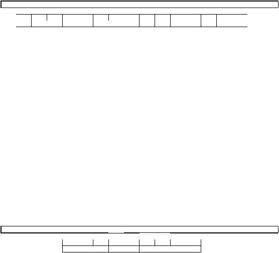
MODEL EXPLANATION |
|
|
|
|
|
|||
R |
9 |
6 |
V |
A |
0 |
4 |
0 |
2 |
3 |
1 |
7 |
M |
S |
A |
(1) |
(2) |
|
(3) |
(4) |
|
(5) |
|
(6) |
(7) |
(8) |
|
(9) |
(10) |
(11) |
(1) |
TRADEBRAND IDENTIFICATION |
|
|
|
(7) |
AIRFLOW |
|
|
|
|||||
|
|
|
|
|
|
|
|
|
|
3 = Up to 3 tons |
|
|
||
(2) |
SERIES |
|
|
|
|
|
|
|
|
5 = Up to 5 tons |
|
|
||
|
96 % Efficient |
|
|
|
|
|
|
|
|
|
|
|
|
|
|
|
|
|
|
|
|
|
|
(8) |
CABINET WIDTH |
|
|
||
(3) |
MOTOR TYPE |
|
|
|
|
|
|
|
14 = 14.0 |
|
|
|
|
|
|
|
|
|
|
|
|
inch |
|
|
|
|
|||
|
|
|
|
|
|
|
|
|
|
|
|
|
|
|
|
V = Variable Speed |
|
|
|
|
|
|
17 = 17.5 |
|
|
|
|
||
|
|
|
|
|
|
|
inch |
|
|
|
|
|||
|
|
|
|
|
|
|
|
|
|
|
|
|
|
|
|
|
|
|
|
|
|
|
|
|
21 = 21.0 |
|
|
|
|
|
|
|
|
|
|
|
|
|
|
inch |
|
|
|
|
(4) |
MAJOR REVISION |
|
|
|
|
|
|
24 = 24.5 |
|
|
|
|
||
|
|
|
|
|
|
inch |
|
|
|
|
||||
|
|
|
|
|
|
|
|
|
|
|
|
|
|
|
A = 1st Design
Series
|
|
|
|
|
|
|
|
(9) |
CONFIGURATION |
|
(5) |
HEATING INPUT DESIGNATION |
|
|
|
|
M = Multi-Position |
||||
|
040 |
= 42,000 |
|
|
|
|
|
|
|
|
|
BTU/HR |
|
|
|
|
|
|
|
|
|
|
060 |
= 56,000 |
|
|
|
|
|
(10) |
STANDARD/Nox |
|
|
BTU/HR |
|
|
|
|
|
||||
|
|
|
|
|
|
|
|
|
||
|
070 |
= 70,000 |
|
|
|
|
|
|
S = Standard |
|
|
BTU/HR |
|
|
|
|
|
|
|||
|
|
|
|
|
|
|
|
|
||
|
085 |
= 84,000 |
|
|
|
|
|
|
N = NOx |
|
|
BTU/HR |
|
|
|
|
|
|
|
||
|
|
|
|
|
|
|
|
|
||
|
100 |
= 98,000 |
|
|
|
|
|
|
|
|
|
BTU/HR |
|
|
|
|
|
|
|
|
|
|
115 |
= 112,000 BTU/HR |
|
|
|
|
|
(11) |
MINOR REVISION |
|
|
|
|
|
|
|
|
|
|
A = First Time Release |
|
(6) |
STAGE - TWO (2) |
|
|
|
|
|
|
B = First Revision |
||
|
|
|
|
SERIAL NUMBER EXPLANATION |
|
|||||
|
|
W |
0 |
8 |
1 |
3 |
9 |
9 |
9 |
9 |
|
|
(1) |
|
(2) |
|
(3) |
|
|
(4) |
|
(1)PLANT CODE
(2)WEEK (DATE CODE)
(3)YEAR
(4)PRODUCTION NUMBER
Note: For Gas Code, see Control System Gas Code on Rating Plate
17-September-2018
92-42800-R96VA
Page 3 of 21

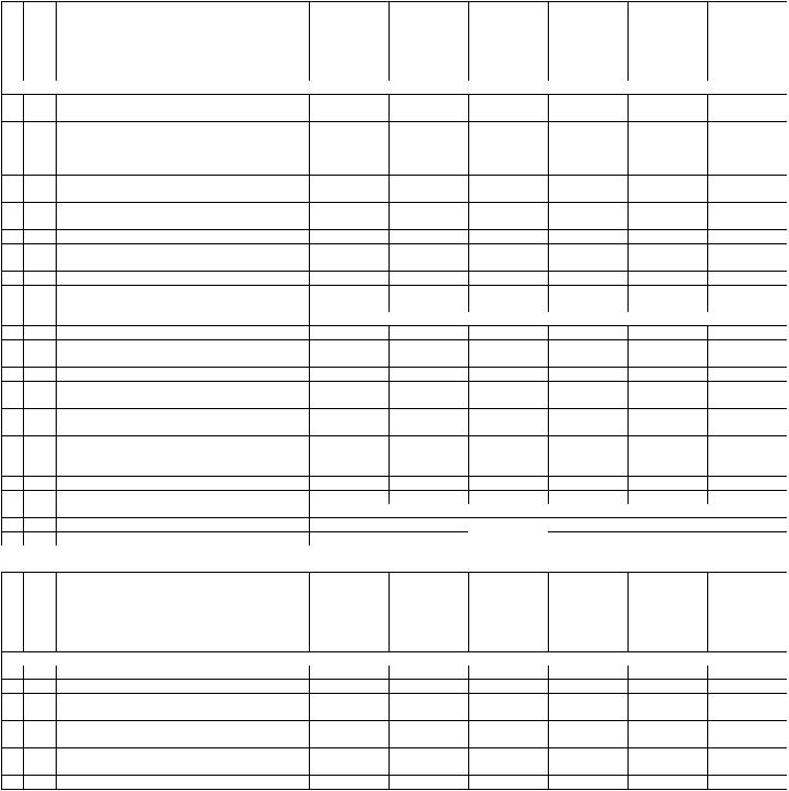
|
|
MODEL |
R96VA |
R96VA |
R96VA |
R96VA |
R96VA |
R96VA |
|
|
INPUT |
040 |
060 |
070 |
085 |
100 |
115 |
No. Notes STAGE |
2 |
2 |
2 |
2 |
2 |
2 |
||
|
|
AIRFLOW |
3 |
3 |
3 |
5 |
5 |
5 |
|
|
CABINET WIDTH |
17 |
17 |
17 |
21 |
21 |
24 |
|
|
CONFIGURATION |
MSA |
MSA |
MSA |
MSA/MSB |
MSA |
MSA |
|
|
|
|
|
|
|||
|
|
PANELS, SHEET METAL, AND MISCELLANEOUS |
|
|
|
|||
1 |
|
Jacket Assembly |
|
|
See Note 1 |
|
|
|
1a |
|
Round Flush Mount Plug - 7/8 in. (6) |
45-103596-06 |
45-103596-06 |
45-103596-06 |
45-103596-06 |
45-103596-06 |
45-103596-06 |
1b |
|
Rectangular Flush Mount Plug - 1-27/32 x 2-1/2 in. |
45-104315-01 |
45-104315-01 |
45-104315-01 |
45-104315-01 |
45-104315-01 |
45-104315-01 |
|
(3) |
|||||||
|
|
|
|
|
|
|
|
|
1c |
|
Round Flush Mount Plug - 2 in. |
45-103596-03 |
45-103596-03 45-103596-03 45-103596-03 |
45-103596-03 |
45-103596-03 |
||
1d |
|
Round Flush Mount Plug - 2-3/8 in. |
45-103596-04 |
45-103596-04 45-103596-04 45-103596-04 |
45-103596-04 |
45-103596-04 |
||
1e |
|
Round Flush Mount Plug - 3-7/16 in. |
45-103596-01 |
45-103596-01 45-103596-01 45-103596-01 |
45-103596-01 |
45-103596-01 |
||
1f |
|
Star Bushing |
45-18515-01 |
45-18515-01 |
45-18515-01 45-18515-01 |
45-18515-01 |
45-18515-01 |
|
1g |
|
Vinyl Grommet - 7/8 in. |
56-22114-06 |
56-22114-06 |
56-22114-06 56-22114-06 |
56-22114-06 |
56-22114-06 |
|
1h |
|
Insulation - Foil Back |
68-103536-01 |
68-103536-01 68-103536-01 68-103536-02 |
68-103536-02 |
68-103536-03 |
||
1i |
|
Insulation - Sound |
68-103537-01 |
68-103537-01 68-103537-01 68-103537-02 |
68-103537-02 |
68-103537-03 |
||
1j |
|
Insulation Retainer (2) |
AE-67925-01 |
AE-67925-01 |
AE-67925-01 AE-67925-01 |
AE-67925-01 |
AE-67925-01 |
|
2a |
|
Top Plate Assembly |
AS-104134-01 |
AS-104134-01 AS-104134-01 AS-104134-02 AS-104134-02 AS-104134-03 |
||||
2b |
|
Left Jacket Baffle |
AE-104192-02 |
AE-104192-03 AE-104192-01 AE-104192-04 AE-104192-01 AE-104192-06 |
||||
2c |
|
Right Jacket Baffle |
AE-104191-02 |
AE-104191-03 AE-104191-01 AE-104191-04 AE-104191-01 AE-104191-06 |
||||
2d |
|
Rear Jacket Baffle |
AE-104190-01 |
AE-104190-01 AE-104190-01 AE-104190-02 AE-104190-02 AE-104190-03 |
||||
3 |
|
Burner Compartment Door - Upper Door |
AS-104040-01 |
AS-104040-01 AS-104040-01 AS-104040-02 AS-104040-02 AS-104040-03 |
||||
4 |
|
Blower/Filter Door - Lower Door |
AS-104041-01 |
AS-104041-01 AS-104041-01 AS-104041-02 AS-104041-02 |
AS-104041-03 |
|||
|
|
Door Filler (with integral molded alignment pins) |
68-104374-11 |
68-104374-11 |
68-104374-11 |
68-104374-12 |
68-104374-12 |
68-104374-13 |
|
|
Door Latch Kit (includes two of each: Latch Cam, |
PD644035 |
PD644035 |
PD644035 |
PD644035 |
PD644035 |
PD644035 |
|
|
Latch Handle, O-Ring, Retainer Screw) |
||||||
|
|
|
|
|
|
|
|
|
|
|
Sight Glass - Door |
68-21893-04 |
68-21893-04 |
68-21893-04 68-21893-04 |
68-21893-04 |
68-21893-04 |
|
5 |
|
Control Board Mounting Plate |
AE-103589-01 |
AE-103589-01 AE-103589-01 AE-103589-01 AE-103589-01 AE-103589-01 |
||||
6a |
|
Junction Box |
AE-61475-03 |
AE-61475-03 |
AE-61475-03 AE-61475-03 |
AE-61475-03 |
AE-61475-03 |
|
6b |
|
Juncton Box Cover |
AE-61476-03 |
AE-61476-03 |
AE-61476-03 AE-61476-03 |
AE-61476-03 |
AE-61476-03 |
|
7 |
|
Transiton - Outlet Air |
68-104133-02 |
68-104133-02 68-104133-02 68-104133-02 |
68-104133-02 |
68-104133-02 |
||
8 |
|
Transition - Gasket |
68-24022-03 |
68-24022-03 |
68-24022-03 68-24022-03 |
68-24022-03 |
68-24022-03 |
|
9 |
|
Transition - Outlet Air Elbow |
68-104145-03 |
68-104145-03 68-104145-03 68-104145-03 |
68-104145-03 |
68-104145-03 |
||
9a |
|
Exhaust Coupling |
68-104146-02 |
68-104146-02 68-104146-02 68-104146-02 |
68-104146-02 |
68-104146-02 |
||
9b |
|
Rubber Plug |
56-104377-01 |
56-104377-01 56-104377-01 56-104377-01 |
56-104377-01 |
56-104377-01 |
||
9c |
|
Bushing - Inducer Coupling Insert (2) |
68-104520-01 |
68-104520-01 68-104520-01 68-104520-01 68-104520-01 68-104520-01 |
||||
9d |
|
Coupling - IDB |
PD703024 |
PD703024 |
PD703024 |
PD703024 |
PD703024 |
PD703024 |
10 |
Stk,3 |
Water Trap - Condensate Drain (See Note 3 for |
68-104346-01 |
68-104346-01 |
68-104346-01 |
68-104346-01 |
68-104346-01 |
68-104346-01 |
|
|
Gasket) |
|
|
|
|
|
|
|
Stk,3 Condensate Trap Gasket (See Note 3) |
68-104151-01 |
68-104151-01 68-104151-01 68-104151-01 |
68-104151-01 |
68-104151-01 |
|||
11a |
|
Drain Tube (from Collector Box) |
AE-61737-06 |
AE-61737-06 |
AE-61737-06 AE-61737-06 |
AE-61737-06 |
AE-61737-06 |
|
11b |
|
Drain Tube D (from Outlet Air Elbow) |
79-104393-01 |
79-104393-01 79-104393-01 79-104393-01 |
79-104393-01 |
79-104393-01 |
||
11c |
|
Drain Tube A (from Condensate Trap) |
79-104394-01 |
79-104394-01 79-104394-01 79-104394-01 |
79-104394-01 |
79-104394-01 |
||
11d |
|
Hose Clamp (5/8 in. for Drain Tube A) |
64-104619-01 |
64-104619-01 64-104619-01 64-104619-01 |
64-104619-01 |
64-104619-01 |
||
11e |
|
Water Trap Mounting Bracket |
AE-104385-01 |
AE-104385-01 AE-104385-01 AE-104385-01 AE-104385-01 |
AE-104385-01 |
|||
11f |
|
Rubber Plug |
56-104377-01 |
56-104377-01 56-104377-01 56-104377-01 |
56-104377-01 |
56-104377-01 |
||
12a |
|
Bottom Plate Assembly |
AS-104314-01 |
AS-104314-01 AS-104314-01 AS-104314-02 AS-104314-02 AS-104314-03 |
||||
12b |
|
Solid Bottom Assembly |
AS-104772-01 |
AS-104772-01 |
AS-104772-01 |
AS-104772-02 |
AS-104772-02 |
AS-104772-03 |
12c |
|
Blower Shelf Assembly (includes items 12d, 12e, |
AS-104135-04 |
AS-104135-01 |
AS-104135-01 |
AS-104135-02 |
AS-104135-02 |
AS-104135-03 |
|
12f) |
|||||||
|
|
|
|
|
|
|
|
|
12d |
|
Bracket Door Mounting |
AE-104332-01 |
AE-104332-01 AE-104332-01 AE-104332-02 AE-104332-02 |
AE-104332-03 |
|||
12e |
|
Round Flush Mount Plug - 2-3/8 in. (2) |
45-103596-04 |
45-103596-04 45-103596-04 45-103596-04 |
45-103596-04 |
45-103596-04 |
||
12f |
|
Support - Heat Exchanger |
AE-104127-01 |
AE-104127-01 AE-104127-01 AE-104127-02 AE-104127-02 |
AE-104127-03 |
|||
12g |
|
Gasket - Blower Shelf |
68-104382-01 |
68-104382-01 68-104382-01 68-104382-02 |
68-104382-02 |
68-104382-03 |
||
12h |
|
Gasket - Door |
AE-61951-54 |
AE-61951-54 |
AE-61951-54 |
AE-61951-55 |
AE-61951-55 |
AE-61951-56 |
20 |
|
Pressure Switches |
|
|
See Electrical Group |
|
|
|
a,b |
|
|
|
|
|
|||
|
|
|
|
|
|
|
|
|
21 |
|
Door Switch - Push Button |
|
|
See Electrical Group |
|
|
|
22 |
|
Limit - Main Limit (Heat Exchanger Panel) |
|
|
See Electrical Group |
|
|
|
23 |
|
Limit - Manual Reset (Burner Compartment) |
|
|
See Electrical Group |
|
|
|
24 |
|
Transformer |
|
|
See Electrical Group |
|
|
|
25a |
|
Induced Draft Blower (IDB) |
|
|
See Electrical Group |
|
|
|
29a |
|
Wiring Harness Assembly (Twist-Lock) |
|
|
See Electrical Group |
|
|
|
30 |
|
Blower Assembly |
|
|
See Blower Group |
|
|
|
31a |
|
Housing w/Blower Wheel |
|
|
See Blower Group |
|
|
|
40 |
|
Heat Exchanger Assembly |
|
See Heat Exchanger/Burner/Manifold Group |
|
|||
41f |
|
O-Ring (fits over tap and seats on Collector Box) |
|
See Heat Exchanger/Burner/Manifold Group |
|
|||
42 |
|
Burner Assembly |
|
See Heat Exchanger/Burner/Manifold Group |
|
|||
47 |
|
Manifold (w/o Orifices) |
|
See Heat Exchanger/Burner/Manifold Group |
|
|||
50 |
|
Gas Valve |
|
|
See Gas Controls |
|
|
|
51 |
|
Integrated Furnace Control Board (IFC) |
|
|
See Gas Controls |
|
|
|
|
|
Touch-up Paint - Granite/Steel Gray (Aerosol) |
PD523018 |
PD523018 |
PD523018 |
PD523018 |
PD523018 |
PD523018 |
|
|
Touch-up Paint - Granite/Steel Gray (Paint Pens) |
PD523019 |
PD523019 |
PD523019 |
PD523019 |
PD523019 |
PD523019 |
|
|
|
|
|
|
|
17-September-2018 |
|
|
|
|
|
|
|
|
92-42800-R96VA |
|
Page 4 of 21

|
MODEL |
R96VA |
|
INPUT |
All |
No. Notes STAGE |
All |
|
|
AIRFLOW |
All |
|
CABINET WIDTH |
All |
|
CONFIGURATION |
All |
|
|
|
|
|
PARTS BAG |
Stk |
Complete Parts Bag (includes items 1 - 9) |
68-104446-01 |
1 |
Intake Coupling / Locknut Assy with O-Ring (2 in.) |
68-24114-02 |
2 |
Air Diffuser |
68-104515-01 |
3 |
Bulkhead Coupling |
68-104005-01 |
4 |
Hose Clamp (5/8 in.) (3) |
64-103686-03 |
5 |
Shorty Plug (1/4 in.) |
45-24125-01 |
6 |
Screw (2) |
63-24368-03 |
7 |
PVC Vane |
68-23473-01 |
8 |
Tube C |
79-105213-01 |
9 |
Hose - Double Elbow |
79-105212-01 |
|
MODEL |
R96VA |
|
INPUT |
All |
No. Notes STAGE |
All |
|
|
AIRFLOW |
All |
|
CABINET WIDTH |
All |
|
CONFIGURATION |
All |
|
|
|
|
|
CONVERSION KIT |
Stk |
Conversion Kit (includes items 1 - 11) |
RXGY-CK |
1 |
Pipe Grommet (2-3/8 in.) |
56-22114-08 |
2 |
Screw (#8 x 1/2 in.) (4) |
63-24368-03 |
3 |
EPDM Trap Plug (.559 in.) |
56-104377-02 |
4 |
Vinyl Cap (1/2 in.) |
56-103685-02 |
5 |
Flush Mount Plug - (2-5/8 in.) |
45-103596-05 |
6 |
Drain Hose (Hose B - 5/8 in.) |
79-104394-02 |
7 |
Drain Hose (Hose E - 1/2 in.) |
79-104393-02 |
8 |
Vent Tube (1/4 in.) |
AE-61737-36 |
9 |
Condensate Trap Bracket (Down Flow) |
AE-104363-01 |
10 |
Condensate Trap Gasket |
68-104151-01 |
11 |
Drain Hose (Hose F - 1/2 in.) |
79-104393-03 |
|
MODEL |
R96VA |
|
INPUT |
All |
No. Notes STAGE |
All |
|
|
AIRFLOW |
All |
|
CABINET WIDTH |
All |
|
CONFIGURATION |
All |
|
|
|
|
ZERO CLEARANCE DOWNFLOW KIT |
|
Stk |
Zero Clearance Downflow Kit (includes items 1 - 5) |
RXGY-ZK |
1 |
Screw (#8 x 1/2 in.) (10) |
63-24368-03 |
2 |
Pipe Collar Gasket Assembly |
68-103580-03 |
3 |
Drain Hose (Hose G - 1/2 in.) |
79-104393-04 |
4 |
Air Intake Pipe |
68-104074-01 |
5 |
Flue Pipe Assembly w/O-ring |
68-104193-01 |
17-September-2018
92-42800-R96VA
Page 5 of 21
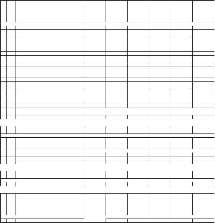
MODEL |
R96VA |
R96VA |
R96VA |
R96VA |
R96VA |
R96VA |
INPUT |
040 |
060 |
070 |
085 |
100 |
115 |
No. Notes STAGE |
2 |
2 |
2 |
2 |
2 |
2 |
AIRFLOW |
3 |
3 |
3 |
5 |
5 |
5 |
CABINET WIDTH |
17 |
17 |
17 |
21 |
21 |
24 |
CONFIGURATION |
MSA |
MSA |
MSA |
MSA/MSB |
MSA |
MSA |
|
|
|
|
|
|
|
|
ELECTRIC GROUP |
|
|
|
|
|
20a |
Stk |
Pressure Switch Assembly (High Fire) - Before |
|
|
approximate Date Code 5116 |
20b |
Stk |
Pressure Switch Assembly (Low Fire) - Before |
|
|
approximate Date Code 5116 |
20a |
Stk |
Pressure Switch Assembly (High Fire) - On or After |
|
|
approximate Date Code 5116 |
20b |
Stk |
Pressure Switch Assembly (Low Fire) - On or After |
|
|
approximate Date Code 5116 |
20c |
|
Silicon Tubing - Pressure Switch |
20d |
|
Tee |
20e |
|
Silicon Tubing - Pressure Switch |
20f |
|
Silicon Tubing - Pressure Switch |
21 |
|
Door Switch - Push Button |
22 |
Stk |
Limit - Main Limit (Heat Exchanger Panel) |
23 |
Stk |
Limit - Manual Reset (Burner Compartment) |
|
|
Bracket (Limit - Manual Reset) |
24 |
Stk |
Transformer |
25a |
Stk |
IDB - Induced Draft Blower (with Gasket) |
25b |
|
Gasket - Induced Draft Blower |
25c |
|
Capacitor - Induced Draft Blower |
26 |
|
Power Factor Choke (PFC) |
|
|
Memory Module for IFC |
|
|
Wiring Harness Assembly (4 pin to 4 pin, IFC to |
|
|
IBM) |
|
|
Wiring Assembly (2 pin jumper for PFC) |
|
|
Wiring Harness Assembly (5 pin from motor to 2 pin |
|
|
on PFC) |
29a |
|
Wiring Harness Assembly (Twist-Lock) |
29b |
|
Wire Assembly (Junction Box to Twist Lock) |
52 |
|
Flame Sensor |
|
|
Water Sensor (2) |
53 |
|
Spark Ignitor |
42-102070-11 |
42-102070-05 42-102070-05 42-102070-18 |
42-102070-14 |
42-102070-13 |
||
42-102069-08 |
42-102069-06 42-102069-06 42-102069-06 |
42-102069-06 |
42-102069-03 |
||
42-105583-08 |
42-105583-10 42-105583-10 42-105583-12 |
42-105583-04 |
42-105583-11 |
||
42-105499-09 |
42-105499-08 42-105499-08 42-105499-08 |
42-105499-08 |
42-105499-07 |
||
AE-61737-20 |
AE-61737-20 |
AE-61737-20 AE-61737-20 |
AE-61737-20 |
AE-61737-20 |
|
79-22461-02 |
79-22461-02 |
79-22461-02 79-22461-02 |
79-22461-02 |
79-22461-02 |
|
AE-61737-06 |
AE-61737-06 |
AE-61737-06 AE-61737-06 |
AE-61737-06 |
AE-61737-06 |
|
AE-61737-23 |
AE-61737-23 |
AE-61737-23 AE-61737-23 |
AE-61737-23 |
AE-61737-23 |
|
42-22692-09 |
42-22692-09 |
42-22692-09 42-22692-09 |
42-22692-09 |
42-22692-09 |
|
47-104465-02 |
47-104465-01 47-104465-01 47-104465-01 |
47-104465-01 |
47-104465-02 |
||
47-104888-01 |
47-22861-04 |
47-22861-04 47-22861-04 |
47-22861-04 |
47-104888-01 |
|
(2) |
(2) |
(2) |
(2) |
(2) |
(3) |
|
See Heat Exchanger/Burner Manifold Group |
|
|||
46-102856-02 |
46-102856-02 46-102856-02 46-102856-02 |
46-102856-02 |
46-102856-02 |
||
70-104157-03 |
70-104157-03 70-104157-03 70-104157-03 |
70-104157-03 |
70-104157-04 |
||
68-104152-01 |
68-104152-01 68-104152-01 68-104152-01 |
68-104152-01 |
68-104152-01 |
||
43-25134-35 |
43-25134-35 |
43-25134-35 43-25134-35 |
43-25134-35 |
43-25134-35 |
|
N/A |
N/A |
N/A |
46-24256-05 |
46-24256-05 |
46-24256-05 |
47-104778-06 |
47-104778-01 47-104778-02 47-104778-03 |
47-104778-04 |
47-104778-07 |
||
45-102785-01 |
45-102785-01 45-102785-01 45-102785-01 |
45-102785-01 |
45-102785-01 |
||
45-104318-01 |
45-104318-01 |
45-104318-01 |
N/A |
N/A |
N/A |
45-104317-01 |
45-104317-01 45-104317-01 45-104317-01 |
45-104317-01 |
45-104317-01 |
||
45-104202-01 |
45-104202-01 45-104202-01 45-104202-01 |
45-104202-01 |
45-104202-04 |
||
45-24371-58 |
45-24371-58 |
45-24371-58 45-24371-58 |
45-24371-58 |
45-24371-58 |
|
|
|
See Gas Controls |
|
|
|
|
See Heat Exchanger/Burner Manifold Group |
|
|||
|
|
See Gas Controls |
|
|
|
|
|
MODEL |
R96VA |
R96VA |
R96VA |
R96VA |
R96VA |
R96VA |
|
|
INPUT |
040 |
060 |
070 |
085 |
100 |
115 |
No. Notes STAGE |
2 |
2 |
2 |
2 |
2 |
2 |
||
|
|
AIRFLOW |
3 |
3 |
3 |
5 |
5 |
5 |
|
|
CABINET WIDTH |
17 |
17 |
17 |
21 |
21 |
24 |
|
|
CONFIGURATION |
MSA |
MSA |
MSA |
MSA/MSB |
MSA |
MSA |
|
|
|
|
|
|
|
|
|
|
|
|
BLOWER GROUP |
|
|
|
|
|
30 |
Stk |
Blower Assembly (Includes items listed below): |
AS-104532-04 AS-104532-01 |
AS-104532-01 AS-104532-02 AS-104532-02 AS-104532-05 |
||||
31a |
|
Housing w/Blower Wheel |
70-104182-03 70-104182-05 70-104182-05 70-104182-07 70-104182-07 70-104182-09 |
|||||
31b |
Stk |
Blower Wheel |
PD703026 |
PD703027 |
PD703027 |
PD703028 |
PD703028 |
PD703029 |
32 |
Stk |
Blower Motor |
51-102602-01 51-102602-01 |
51-102602-01 51-102603-01 51-102603-01 |
51-102603-01 |
|||
|
Stk |
Belly Band Motor Mount Kit (includes Motor Mount |
AS-53148-91 |
AS-53148-91 |
AS-53148-91 |
AS-53148-91 |
AS-53148-91 |
AS-53148-91 |
|
|
Arms, Belly Band and Mounting Hardware) |
|
|
|
|
|
|
33 |
|
ECM Motor Mount (Belly Band) |
70-19927-04 70-19927-04 |
70-19927-04 70-19927-04 |
70-19927-04 |
70-19927-04 |
||
34 |
|
Motor Mount Arm (4) |
70-19929-10 70-19929-10 |
70-19929-10 70-19929-10 |
70-19929-10 |
70-19929-10 |
||
35 |
|
Screw - Motor Mount Arm (4) |
63-101978-01 |
63-101978-01 |
63-101978-01 |
63-101978-01 |
63-101978-01 |
63-101978-01 |
17-September-2018
92-42800-R96VA
Page 6 of 21
|
|
MODEL |
R96VA |
R96VA |
R96VA |
R96VA |
R96VA |
R96VA |
|
|
INPUT |
040 |
060 |
070 |
085 |
100 |
115 |
No. Notes STAGE |
2 |
2 |
2 |
2 |
2 |
2 |
||
|
|
AIRFLOW |
3 |
3 |
3 |
5 |
5 |
5 |
|
|
CABINET WIDTH |
17 |
17 |
17 |
21 |
21 |
24 |
|
|
CONFIGURATION |
MSA |
MSA |
MSA |
MSA/MSB |
MSA |
MSA |
|
|
|
|
|
|
|||
|
|
HEAT EXCHANGER, BURNER / MANIFOLD GROUP |
|
|
|
|||
40 |
Stk |
Heat Exchanger Assembly |
AS-104120-01 AS-104120-10 AS-104120-31 AS-104120-18 AS-104120-19 AS-104120-21 |
|||||
40 |
Stk |
Heat Exchanger Assembly - Option 321 Models |
N/A |
AS-104900-01 |
AS-104900-02 |
AS-104900-03 |
AS-104900-04 |
N/A |
|
|
(Stainless Steel Primary Burner Tubes) |
|
|
|
|
|
|
|
|
Collector Box Kit (includes Collector Box Gasket, |
|
|
|
|
|
|
41a |
Stk |
Rubber Plugs, Water Sensors, O-Ring, Vinyl Cap, |
68-104111-81 |
68-104111-95 |
68-104111-96 |
68-104111-97 |
68-104111-98 |
68-104111-83 |
|
|
IDB Gasket and Mounting Screws) |
|
|
|
|
|
|
41b |
Stk |
Collector Box Gasket |
68-103546-03 68-103546-03 |
68-103546-03 68-103546-02 68-103546-02 |
68-103546-01 |
|||
41c |
|
Rubber Plug (2) |
56-104377-01 56-104377-01 |
56-104377-01 56-104377-01 56-104377-01 |
56-104377-01 |
|||
41d |
|
Vinyl Cap |
56-103685-01 56-103685-01 |
56-103685-01 56-103685-01 56-103685-01 |
56-103685-01 |
|||
41e |
Stk |
Water Sensor (2) |
47-104184-01 47-104184-01 |
47-104184-01 47-104184-01 47-104184-01 |
47-104184-01 |
|||
41f |
|
O-Ring (fits over tap and seats on Collector Box) |
68-104386-02 |
68-104386-02 |
68-104386-02 |
68-104386-02 |
68-104386-02 |
68-104386-02 |
42 |
|
Burner Assembly (Rack, Cover, Burner Halves, |
AS-104123-01 |
AS-104123-02 |
AS-104123-03 |
AS-104123-04 |
AS-104123-05 |
AS-104123-06 |
|
Ignitor Bracket) |
|||||||
|
|
|
|
|
|
|
|
|
43 |
|
Burner Rack (One Piece Assemby) |
AE-104121-01 AE-104121-02 |
AE-104121-03 AE-104121-04 AE-104121-05 AE-104121-06 |
||||
44 |
|
Burner Rack Cover |
AE-104122-01 AE-104122-02 |
AE-104122-03 AE-104122-04 AE-104122-05 AE-104122-06 |
||||
44a |
|
Screw - Burner Cover (2) |
63-22153-01 63-22153-01 |
63-22153-01 63-22153-01 |
63-22153-01 |
63-22153-01 |
||
45 |
|
Igniter Bracket |
AE-61885-02 AE-61885-02 |
AE-61885-02 AE-61885-02 |
AE-61885-02 |
AE-61885-02 |
||
45a |
|
Bracket (Limit - Manual Reset) |
N/A |
N/A |
N/A |
N/A |
N/A |
AE-61913-02 |
46 |
Stk |
Burner |
AS-61984-03 AS-61984-04 |
AS-61984-05 AS-61984-06 |
AS-61984-07 |
AS-61984-08 |
||
46a |
|
Screw - Burner to Burner Rack |
63-22153-05 |
63-22153-05 |
63-22153-05 |
63-22153-05 |
63-22153-05 |
63-22153-05 |
|
(5) |
(6) |
(7) |
(8) |
(9) |
(10) |
||
|
|
|
||||||
47 |
|
Manifold (w/o Orifices) |
81-104526-01 |
81-104526-02 |
81-104526-03 81-104526-04 81-104526-05 81-104526-06 |
|||
|
|
Burner Orifice - Natural Gas |
|
|
See Orifice Selection Chart |
|
|
|
|
|
Burner Orifice - LP |
|
|
See Orifice Selection Chart |
|
|
|
|
|
Number of Orifices |
(3) |
(4) |
(5) |
(6) |
(7) |
(8) |
No. Notes MODEL |
R96VA |
R96VA |
R96VA |
|
|
|
||
|
|
GAS CODE |
JE |
KG |
KM |
|
|
|
|
|
|
GAS CONTROLS |
|
|
|
|
|
50 |
Stk |
Gas Valve - Natural Gas |
60-101921-05 60-101921-05 60-101921-05 |
|
|
|
||
|
Stk,2 |
Gas Valve - LP |
See Note 2 |
See Note 2 |
See Note 2 |
|
|
|
51 |
Stk |
Integrated Furnace Control Board (IFC) |
62-104061-01 |
62-104061-04 62-104061-05 |
|
|
|
|
|
|
Memory Module for IFC |
|
|
See Electrical Group |
|
|
|
52 |
Stk |
Flame Sensor |
62-23543-08 62-23543-08 |
62-23543-08 |
|
|
|
|
53 |
Stk |
Spark Ignitor |
62-24141-05 62-24141-05 |
62-24141-05 |
|
|
|
|
|
Stk |
LP Conversion Kit - U.S./Canadian Models |
FP-34 |
FP-34 |
FP-34 |
|
|
|
No. Notes MODEL |
R96VA |
|
|
|
|
|
||
|
|
GAS CODE |
ALL |
|
|
|
|
|
|
|
|
OUTDOOR SENSOR ACCESSORY KIT |
|
|
|
||
|
|
Outdoor Sensor Kit |
RXGY-J02 |
|
|
|
|
|
|
|
MODEL |
R96VA |
R96VA |
R96VA |
R96VA |
R96VA |
R96VA |
|
|
INPUT |
040 |
060 |
070 |
085 |
100 |
115 |
No. Notes STAGE |
2 |
2 |
2 |
2 |
2 |
2 |
||
|
|
AIRFLOW |
3 |
3 |
3 |
5 |
5 |
5 |
|
|
CABINET WIDTH |
17 |
17 |
17 |
21 |
21 |
24 |
|
|
CONFIGURATION |
MSA |
MSA |
MSA |
MSA/MSB |
MSA |
MSA |
|
|
|
|
|
|
|||
|
|
HIGH ALTITUDE AIRFLOW ADJUSTMENT KITS |
|
|
|
|||
|
|
Airflow Adjustment Kit |
RXGY-F58 |
RXGY-F59 |
RXGY-F60 |
RXGY-F61 |
RXGY-F62 |
RXGY-F63 |
17-September-2018
92-42800-R96VA
Page 7 of 21
 Loading...