

Page 1
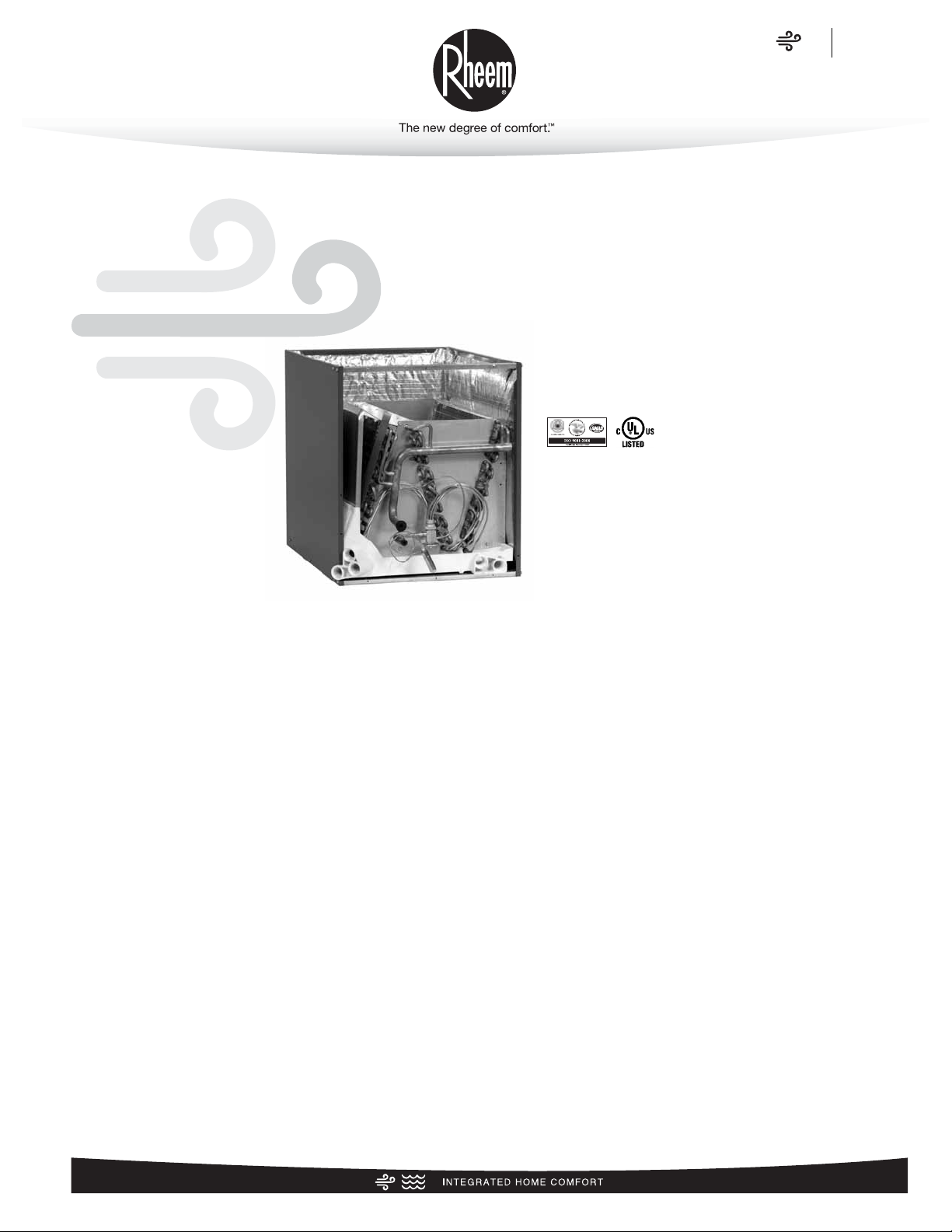
Cased/Uncased Coils
For Gas And Oil Furnaces
FORM NO. C11-220
RCFL- Series
featuring Industry Standard R-410A
Refrigerant
Airflow Capacity
600-1,900 CFM [283-897 L/s]
• Rheem
®
Indoor Coils are designed for use with Rheem outdoor units and are available for vertical upflow or downflow,
and horizontal left or horizontal right airflow. When matched
with Rheem outdoor units, the coils provide a nominal capacity range from 18,000 BTU/HR [5.24 kW] to 48,000 BTU/HR
[14.06 kW].
• Constructed of aluminum fins bonded to internally grooved
copper tubing.
• Tin plated copper tubing in the finned area for superior corro-
sion resistance in harsh environments.
• Coils are tested at the factory with an extensive refrigerant
leak check.
• Coils have sweat refrigerant connections.
• Ideally suited for new installations or add on air conditioning.
• Feature two sets of
3
/4" [14.1 mm] N.P.T. Condensate drain
connections for ease of connection.
• Coils are AHRI certified for system application with variety of
Rheem outdoor units.
• Condensate drain pan is constructed of high grade, heat
resistant, corrosion free thermal-set material.
• Compatible with Germicidal Light System (UV resistant)
• Bi-Directional airflow eliminates the need to switch any inter-
nal components from horizontal left to right.
• Unique drain pan design maximizes application flexibility and
condensate removal.
• Universal Duct Flanges are included with all coil models.
Air
Indoor Coils
RCFL Series
Page 2

2
Air
Table of Contents
RCFL Series
TABLE OF CONTENTS
Model Number Identification ............................................................................3
Coil Specifications ..........................................................................................3
Coil Dimensions and Weights ..........................................................................4
Accessories ................................................................................................5-6
Limited Warranty ............................................................................................7
Page 3
3
RCF L—HM2414AC
Gas/Oil Furnace Coil
C = Cased
U = Uncased
Design Variation
A = 1st Design
B = 2nd Design
C = 3rd Design
T = Tin plated copper tubing in finned area
Coil Size
14 = 14" [356 mm]
17 = 17.5" [431.8 mm]
21 = 21" [533.4 mm]
24 = 24.5" [609.6 mm]
Nominal Capacity
24/25 = 18,000 to 24,000 BTU/HR
[5.27 to 7.03 kW]
26 = 24,000 BTU/HR [7.03 kW]
36/38 = 30,000 to 36,000 BTU/HR
[8.79 to 10.55 kW]
48 = 42,000 to 48,000 BTU/HR
[12.31 to 14.06 kW]
60 = 60,000 BTU/HR
[17.58 kW]
Cased Coil Airflow:
HM = A/C or Heat Pump, Multi-Position
AU = A/C Only, Upflow/Downflow
Uncased Coil Airflow:
HU = A/C or Heat Pump, Upflow/Downflow
Refrigerant
V = R-410A
F = Product Generation
Classification
C = Coil
Rheem
Model Number Identification
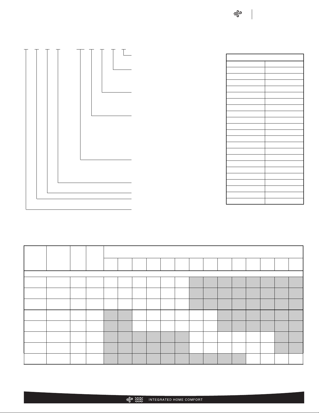
Table 1: Coil Specifications/Airflow Pressure Drop
Coil
Model
RCFL
Approx.
Design
Air Flow
CFM [L/s]
Range
Face
Area
Sq. Ft.
[m
2
]
Fins-in.
Rows
Deep
Static Pressure Drop Through Wet Cooling Coil [kPa] (Inches W.C.) CFM [L/s]
600
[285]
700
[330]
800
[380]
900
[425]
1000
[470]
1100
[519]
1200
[565]
1300
[614]
1400
[660]
1500
[708]
1600
[755]
1700
[802]
1800
[850]
1900
[897]
2417
600/1000
[283/472]
4.56
[0.42]
16/2
.15
[.039]
.19
[.049]
.23
[.059]
.30
[.076]
.38
[.096]
.45
[.113]
— — — — — — — —
3821/4821
1200/1800
[566/850]
8.55
[0.79]
16/2 — — — — — —
.22
[.056]
.25
[.063]
.28
[.071]
.32
[.081]
.36
[.092]
.41
[.103]
— —
3824/4824
1200/1800
[566/850]
8.55
[0.79]
16/2 — — — — — —
.22
[.056]
.25
[.063]
.28
[.071]
.32
[.081]
.32
[.081]
.41
[.103]
— —
HIGH EFFICIENCY COOLING COILS
2621/3621
900/1400
[424/661]
5.70
[0.53]
16/2 — —
.15
[.038]
.18
[.047]
.23
[.058]
.27
[.069]
.31
[.080]
.37
[.094]
— — — — — —
2617/3617
900/1400
[424/661]
5.70
[0.53]
16/2 — —
.17
[.043]
.21
[.053]
.26
[.064]
.31
[.080]
.36
[.092]
.41
[.103]
— — — — — —
6024
1600/1900
[755/897]
9.98
[0.93]
14/3 — — — — — — — — — —
.27
[.070]
.30
[.076]
.34
[.084]
.37
[.094]
2414
600/1000
[283/472]
4.56
[0.42]
16/2
.17
[.043]
.21
[.053]
.25
[.063]
.31
[.080]
.40
[.100]
.46
[.117]
— — — — — — — —
2514
600/1000
[283/472]
4.56
[0.42]
16/2
.22
[.055]
.29
[.072]
.36
[.090]
.44
[.110]
.52
[.130]
576
[.144]
— — — — — — — —
Available Models of RCFL Coils
RCFL-HM2414CC RCFL-HU2514CU
RCFL-HM2514CC RCFL-HU2417CU
RCFL-HM2417CC RCFL-HU3617CU
RCFL-HM3617CC RCFL-HU3621CU
RCFL-HM3621CC RCFL-HU4821CU
RCFL-HM4821CC RCFL-HU4824CU
RCFL-HM4824CC RCFL-HU6024CU
RCFL-HM6024CC RCFL-HU3821CU
RCFL-HM3821CC RCFL-HU3824CU
RCFL-HM3824CC RCFL-HU2617CU
RCFL-HM2617CC RCFL-HU2621CU
RCFL-HM2621CC RCFL-HU2414TU
RCFL-AU2414CC RCFL-HU2514TU
RCFL-AU2514CC RCFL-HU2617TU
RCFL-AU2417CC RCFL-HU2621TU
RCFL-AU3617CC RCFL-HU2417TU
RCFL-AU3621CC RCFL-HU3617TU
RCFL-AU4821CC RCFL-HU3621TU
RCFL-AU4824CC RCFL-HU4821TU
RCFL-AU6024CC RCFL-HU4824TU
RCFL-AU3821CC RCFL-HU6024TU
RCFL-AU3824CC RCFL-HU3821TU
RCFL-HU2414CU RCFL-HU3824TU
Air
Model I.D./Coil Specifications
RCFL Series
NOTE: Represents Coil-Only Airflow Ratings
[ ] Designates Metric Conversions
Page 4

Air
Coil Dimensions and Weights
RCFL Series
4
53/8
[136.5 mm]
SUCTION LINE
LIQUID LINE
1
13
/16 [46 mm]
2
1
/4 [57.1 mm]
1
1
/4
[31.7 mm]
7
/16
[11.1 mm]
5
15
/16
[150.8 mm]
4
1
/8
[104.7 mm]
17/16
[36.5 mm]
21
11
/16
[550.8 mm]
PRIMARY DRAIN
3
/4 N.P.T. (VERTICAL)
PRIMARY DRAIN
3
/4 N.P.T.
(VERTICAL &
HORIZONTAL)
SECONDARY DRAIN
3
/4 N.P.T. (VERTICAL)
NOTE:
FLANGES ARE
PROVIDED
FOR FIELD
INSTALLATION
1
/2 [12.7 mm]
FRONT VIEW
SIDE VIEW
FIGURE 1: DIMENSIONS
➀ Casing top and bottom openings are the same dimensions.
[ ] Designates Metric Conversions
Table 2: Coil Dimensions and Weights
Coil
Model
RCFL
Connections
Cased Coil Dimensions
(in) [mm]
3821/4821
3
/8[9.53]
7
/8[22.23] 21 1/2[533] 257/8[657] 76 [34]
2417
3
/8[9.53]
3
/4[19.05] 171/2[445] 141/2[368] 46 [21]
83 [38]
51 [23]20 1/2[508]
28 1/2[711]
50 [23]2414*/2514*
3
/8[9.53]
3
/4[19.05] 14 1/2[356] 21 1/2[533] 46 [21] 233/16[584]
I.D. I.D.
Shipping Weight
(lbs.) [Kg.]
Liquid Suction
A B
Coil Weight
(lbs.) [Kg.]
C
Sweat (in.) [mm]
118 [55]32 1/2[812]6024
3
/8[9.53]
7
/8[22.23] 241/2[622] 301/4[768] 108 [49]
3824/4824
3
/8[9.53]
7
/8[22.23] 241/2[622] 253/8[645] 89 [40] 99 [45]32 1/2[812]
2621/3621
3
/8[9.53]
3
/4[19.05] 21 1/2[533] 171/2[445]
54 [24] 60 [27]
20 1/2[508]
2617/3617
3
/8[9.53]
3
/4[19.05] 171/2[445] 177/8[454] 52 [24] 57 [26]20 1/2[508]
Weight
PLENUM WIDTH
*The 14 inch, 2 ton RCFL coil (2414) is part of the “N-Coil” design series, even though the coil shape resembles an “A” coil design.
197/8
[505 mm]
A MINUS ONE INCH ➀
Page 5

Air
Accessories
RCFL Series
5
2414/2514 RXHH-A01
3617/3621 RXHH-A03
4821/4824 RXHH-A04
Coil Model Horizontal Adapter Kit Model No.
2417 RXHH-A02
Table 4: Horizontal Adapter Kit Model No.
Accessories
• PLENUM ADAPTER ACCESSORY
RXBA-AE
This plenum adapter accessory is for use with the 24
1
/2" wide
cased indoor cooling and heat pump coils. This allows a 24
1
/2"
wide cased coil to be installed on a 28" wide oil furnace. This is a
field-installed accessory only.
• RXBA-AC (Upflow/Horizontal)
These plenum adapter accessories are for use when a cooling
coil is matched with a gas furnace of one smaller size.
• HORIZONTAL ADAPTER KIT RXHH (See Figure 2)
This horizontal adapter kit is used to convert a upflow or downflow
coil for a horizontal application. See Table 4 to order the proper
horizontal adapter kit.
*Note: The horizontal adapter kit cannot be used for RCFL-AU****BC
applications. It can only be used on RCFL-AU****AC applications
and for RCFL-HU****AC applications.
Table 3: Coil Application
Coils can be matched to heating products as listed in table below.
Coil Model
RCFL
Oil Gas
2414
2417
2514
2617
3617
—
14 [356]
2417
2617
3617
21 [533]
171/2[444]
14 [356]
21 [533]
171/2[444]
Furnace Width
(In.) (mm)
241/2[622]
21 [533]
21 [533]
2621
3621
3821
4821
241/2[622]
3824
4824
6024
AIR FLOW
HORIZONTAL-DUAL
DIRECTION
FIGURE 2: HORIZONTAL ADAPTER KIT ILLUSTRATION
RXBC—D14I
INSULATION
I = Insulated
Blank = Uninsulated
CABINET WIDTH
14 = 14" [356 mm]
17 = 17.5" [444 mm]
21 = 21" [533 mm]
24 = 24.5" [622 mm]
DESIGN SERIES
COIL CASING
BLOWER UNIT
ACCESSORY
RHEEM
Table 5: Unit Dimensions and Weights- RXBC Indoor Coil Casings
• INDOOR COIL CASING- RXBC (See Table 5)
HORIZONTAL ADAPTER KIT (RXHH-)
*Note: Due to the proximity of the drain pan to the high temperature oil furnace drain, horizontal left application is not permitted on all oil furnaces.
B14x20 131/8[333]
B17x20
165/8[422]
Uncased Coil Adapter
Model Number RXBA
A
Width (in.) [mm]
B21x20 201/8[511]
-HUxx14
-HUxx17
Uncased Coil
Model RCFP
-HUxx21
B24x20 235/8[599] -HUxx24
Table 6: Uncased Coil Adapter Kit
[ ] Designates Metric Conversions
Model
Number
RXBC-D14AI 14 [356] 233/16[589]
RXBC-D17AI 171/2[445] 20 [508] 18 [8] 161/2[419]
RXBC-D21AI 21 [533] 20 [508] 20 [9] 20 [508]
RXBC-D21BI 21 [533] 28 [711] 27 [12] 20 [508]
RXBC-D24AI 241/2[622] 321/2[826]
Width
(in.) [mm]
(in.) [mm]
Height
Depth
(in.)
[mm]
215/
[549]
Unit Weight
Weight
(lbs.) [Kg.]
19 [9] 13 [330]
8
34 [16]
Ship. Wt.
(lbs.) [Kg.]
23 [10]
23 [10]
26 [12]
36 [17]
44 [20]
Supply Air/Return
Air Openings
Depth
Width
(in.) [mm]
231/2[597]
(in.)
[mm]
1931/
[508]
32
Page 6

Air
Accessories
RCFL Series
6
FIGURE 4: UNCASED COIL ADAPTER KIT ASSEMBLED
Note: Sliding the coil into the coil rail before attaching coil rack front.
FIGURE 3: UNCASED COIL ADAPTER KIT ILLUSTRATION
• UNCASED COIL ADAPTER KIT
RXBA- (See Figure 3 & 4)
This uncased coil adapter kit is used to adapt the coil to a furnace or ductwork. See Table 6 to order the proper adapter kit.
Each kit contains a quantity of 20 adapters.
Accessories (cont.)
[ ] Designates Metric Conversions
11
/16
7
[196 mm]
11/2
[41 mm]
A
5
20
/16
[516 mm]
Page 7

Air
Limited Warranty
RCFL Series
7
GENERAL TERMS OF LIMITED WARRANTY*
Rheem will furnish a replacement for any part of this product
which fails in normal use and service within the applicable
periods stated, in accordance with the terms of the limited
warranty.
*For complete details of the Limited and Conditional Warranties, including
applicable terms and conditions, contact your local contractor or the
Manufacturer for a copy of the product warranty certificate.
Parts.......................................................................Five (5) Years
Conditional Parts (Registration Required)............Ten (10) Years
Page 8

The new degree of comfort.
™
Rheem Heating, Cooling & Water Heating • P.O. Box 17010
Fort Smith, Arkansas 72917 • www.rheem.com
In keeping with its policy of continuous progress and product improvement, Rheem reserves the right to make changes without notice.
PRINTED IN U.S.A 1/13 QG FORM NO. C11-220
Rheem Canada Ltd./Ltée • 125 Edgeware Road, Unit 1
Brampton, Ontario • L6Y 0P5
 Loading...