


Commercial High Efficiency Water Heater
USE & CARE MANUAL
WITH INSTALLATION INSTRUCTIONS FOR THE CONTRACTOR
For use with the following models:
GHE80SS, GHE80SU
GHE100SS, GHE100SU
CATEGORY IV Models
Fan Assisted Combustion
! |
Recognize this symbol as an indication of important |
! |
Do not destroy this manual. Please read carefully and keep |
safety information! |
in a safe place for future reference. |
!by a qualified, licensed service professional. If the foregoing assumption is not appropriate, then we recommend that you obtain and retain our Residential Use & Care Manual.
!WARNING: If the information in these instructions are not followed exactly, a fire or explosion may result causing property damage, personal injury or death.
!FOR YOUR SAFETY!NOTICE: This water heater is designed for use in a commercial application and the installation and maintenance of it should be performed
-AVOID FIRES AND EXPLOSIONS
•Do not store or use gasoline, other flammable vapors or liquids or other combustible materials in the vicinity of this or any other appliance.
•Doing so may result in a explosion or fire
-WHAT TO DO IF YOU SMELL GAS
•Do not try to light any appliance.
•Do not touch any electrical switch.
•Do not use any phone in your building
•Immediately call your gas supplier from a neighbor's phone. And follow the gas supplier's instructions.
•If you cannot reach your gas supplier, call the fire department.
•Do not return to your building until authorized by the gas supplier or fire department.
-ALWAYS REFER TO THIS MANUAL
•Improper installation, adjustment, alteration, service, or maintenance can cause injury, property damage, or death.
•Installation and service must be performed by a qualified installer, service agency, or gas supplier.
AP19520 (01/18)
TABLE OF CONTENTS
Safety Information
Safety Precautions. . . . . . . . . . 3-4
Introduction
Local Installation Regulations. |
. . . . . |
5 |
|
Water Heater Location. . |
. . |
. . . . . |
5 |
Installation Instructions
Inspect Shipment. . |
. . . . . . . |
. . |
5 |
|||
Water Supply Connections . |
|
. . . . |
. . |
6 |
||
Gas Supply. . . . . . . . . |
. . . . . |
. |
. . . . . . . |
. . . . |
. 6 |
|
Wiring. . |
. . . . . . . . . . . . |
. . |
7 |
|||
Typical Installation. . . |
. . . . |
. |
. . |
|
8 |
|
Vent Installation |
|
|
|
|
|
|
Information for Pipe and Fittings.. . |
. . |
9 |
||||
General Venting Information . |
. . . |
. . |
. 9 |
|||
Joining Pipe and Fittings. . |
|
. . . . |
. 9-10 |
|||
Vent Length Information. . |
. . . . |
. 11-12 |
||||
Vent Terminal Precautions. |
. |
. . . |
. 13-16 |
|||
Horizontal Vent Installation. |
. |
. . . |
17-19 |
|||
Vertical Vent Installation. . |
. . . . |
. 20-22 |
||||
Concentric Vent Installation. |
|
. . . . |
23-29 |
|||
Installation Checklist. |
. . . . . |
. |
. . |
|
30 |
|
Operating Instructions
Ignition Instructions . . . . . . . . . . 31 Water Temperature. . . . . . . . . . 32 Emergency Shut Down. . . . . . . . 32 User Interface . . . . . . . . . . . 33-39
Care and Cleaning
Pressure Switch Inspection. . . . . . |
. 37 |
Venting Inspection. . . . . . . . . . |
37 |
Routine Maintenance . . . . . . |
37 |
Anode Inspection. . . . . . . . . . |
. 37 |
Seasonal Operation . . . . . . . . . |
. 37 |
Venting System Inspection. . . . . . |
37 |
Troubleshooting
Before You Call For Service. . . . . 38-46 Alarm and Alert Codes. . . . . . . .40-46
Customer Service
Parts List . . . . . . . . . . . . . . 47 Wiring Diagrams . . . . . . . . 48 How to Obtain Service Assistance. . . . 52
READ ALL SAFETY INFORMATION
Your safety and the safety of others are very important. There are many important safety messages in this manual and on your appliance. Always read and follow all safety messages.
This is the safety alert symbol. Recognize this
!symbol as an indication of importan safety information! This symbol alerts you to safety hazards that could result in physical harm or death.
All safety messages will follow the safety alert symbol and either the word “DANGER”, “WARNING”, “CAUTION” or “NOTICE”.
These words mean:
! |
DANGER |
An imminently hazardous |
|
|
situation that will result in death |
|
|
or serious injury. |
! |
WARNING |
A potentially hazardous |
|
|
situation that could result in |
|
|
death or serious injury and/or |
|
|
damage to property. |
! CAUTION
NOTICE:
A potentially hazardous situation that may result in minor or moderate injury.
Attention is called to observe a specified procedure or maintain a specific condition.
Quick Guide for Water Heater Operating Conditions:
Min. Inlet Gas Pressure (at gas valve, during ignition to full input):
Natural Gas: |
3.5 |
In. WC |
LP Gas: |
11.0 |
In. WC |
Max. Inlet Gas Pressure (at gas valve, during ignition to full input):
Natural Gas: |
10.5 In. WC |
LP Gas: |
13.0 In. WC |
Electrical:
120 Vac, 60 Hz., 7 amp min. powered required
Basic Clearances for Water Heaters:
To combustibles: 0" for sides and back; 6" for top Recommended for service: 24" for front and top
2

!General Safety Precautions
To meet commercial water use needs, the temperature on this water heater is adjustable up to 185°F (85° C). However, water temperatures over 125°F (52° C) can cause severe burns instantly or death from scalds. This is the preferred starting point for setting the control for supplying general purpose hot water.
Safety and energy conservation are factors to be considered when setting the water temperature. The most energy efficient operation will result when the temperature setting is the lowest value that satisfies the needs consistent with the application.
! D A N G E R
HOT
BURN
Water temperature over 125°F can cause severe burns instantly or death from scalds.
Childen, disabled and elderly persons are at greatest risk of being scalded.
See instructions manual begore setting temperature of water heater.
Fell water Before bathing or showering.
Temperature limiting valves are available, see manual.
Maximum water temperatures occur just after burner has shut off. To find the temperature of the hot water being delivered, turn on a hot water faucet, and place a thermometer in the hot water stream, and read the thermometer.
The following chart details the relationship of water temperature and
time to scald injury and may be used as a guide in determining the safest water temperature for your applications.
TIME / TEMPERATURE RELATIONSHIPS IN SCALDS
|
Temperature |
Time to Produce Serious Burn |
||||
|
120° F (49°C) |
More than 5 minutes |
|
|||
|
125° F (52°C) |
11/2 to 2 minutes |
|
|
|
|
|
130° F (54°C) |
About 30 seconds |
|
|||
|
135° F (57°C) |
About 10 seconds |
||||
|
|
|
|
|||
|
140° F (60°C) |
Less than 5 seconds |
|
|||
|
145° F (63°C) |
Less than 3 seconds |
|
|||
|
150° F (66°C) |
About 11/2 seconds |
|
|||
|
155° F (68°C) |
About 1 second |
|
|||
|
|
Table courtesy of Shriners Burn Institute |
|
|
|
|
The temperature of the water in the heater can be regulated by setting the temperature on the display (see pages 33 & 36). To comply with safety regulations the water heater temperature was set to 120°F (49°C) before the water heater was shipped from the factory. The illustration information on pages 33 & 36 shows the display and how to adjust the water temperature.
! DANGER
Status: Standby
120°
warm |
hot |
very hot |
|
Settings |
Status |
Service |
Disable |
See Section "User Interface" (pages 33 & 36) for setting the temperature.
Hotter water increases the potential for hot water SCALDS.
NOTICE: Mixing valves are recommended for reducing point of use water temperature by mixing hot and cold water in branch water lines. It is recommended that a mixing valve complying with the Standard for Temperature Actuated Mixing Valves for Hot Water Distribution Systems, ASSE 1017 be installed. See page 6 for more details. For additional information, contact a licensed plumber or the local plumbing authority.
3
!General Safety Precautions
Be sure to read and understand the entire Use & Care Manual before attempting to install or operate this water heater. Especially the following General Safety Precautions. Failure to follow these warnings could result in a fire or explosion, causing property damage, bodily injury, or death. Should you have any problems understanding the instructions in this manual, STOP, and get help from a qualified installer, service technician, or gas supplier.
! WARNING
Gasoline, as well as other flammable materials and liquids (adhesives, solvents, etc.) and the vapors they produce, are extremely dangerous. DO NOT handle, use or store gasoline or other flammable or combustible materials anywhere near or in the vicinity of a water heater. Be sure to read and follow the warning label pictured below as well as the other labels on the water heater, and warnings printed in this manual. Failure to do so can result in property damage, bodily injury, or death.
! DANGER
Failure to properly vent the water heater to the outdoors as outlined in the "Venting" section (see pages 8 through 29) of this manual can result in unsafe operation of the water heater. To avoid the risk of fire, explosion, or asphyxiation from carbon monoxide, never operate this water heater unless it is properly vented and has an adequate air supply for proper operation. Be sure to inspect the vent system for proper installation at initial start-up and, at least, annually, thereafter. Refer to the "Maintenance" section (see page 37) of this manual for more information regarding vent system inspections.
! WARNING
Gasoline, as well as other flammable materials and liquids (which include but are not limited to adhesives, solvents, paint Thinners, etc.), and the vapors they produce are extremely dangerous. DO NOT handle, use, or store gasoline or other flammable or combustible materials anywhere near or in the vicinity of a water heater or any other appliance. Be sure to read and follow the warning label pictured below and other labels on the water heater and in this manual. Failure to do so can result in property damage, bodily injury, or death.
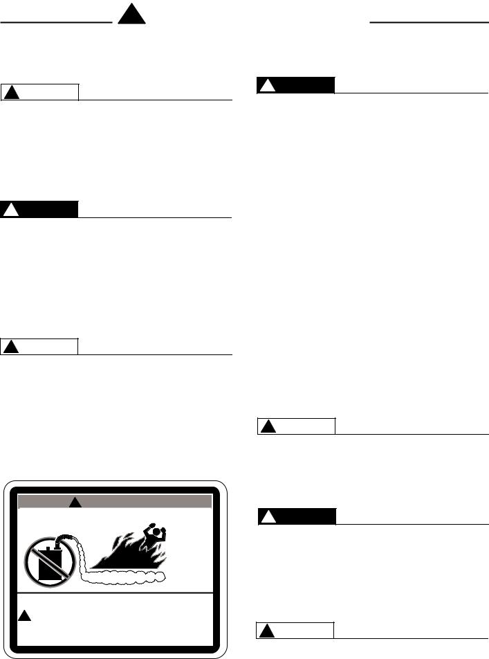
! W A R N I N G
FlammableVapors
FIRE AND EXPLOSION HAZARD
Can result in serious injury or death.
! Do not store or use gasoline or other flammable vapors and liquids in the vicinity of this or any other appliance. Storage or use of gasoline
or other flammable vapors or liquids in the vicinity of this or any other appliance can result in serious injury or death.
! DANGER
LIQUEFIED PETROLEUM MODELS — Propane (LP) gas, must be used with great caution.
•It is heavier than air and will collect first in lower areas making it hard to detect at nose level.
•Make sure to look and smell for LP leaks before attempting ignition of the water heater. Use a soapy solution to check all gas fittings and connections. Bubbling at a connection indicates a leak that must be corrected.
•When smelling to detect an LP leak, be sure to sniff near the floor too.
•Gas detectors are recommended in LP applications and their installation should be in accordance with the manufacturer's recommendations and local laws, rules, regulations, or customs.
•It is recommended that more than one method be used
to detect leaks in LP applications.
IF LP GAS IS PRESENT OR SUSPECTED:
•DO NOT attempt to find the cause yourself;
•DO NOT try to light any appliance;
•DO NOT touch any electrical switch;
•DO NOT use any phone in your building.
•Leave the building immediately and make sure your family and pets leave also.
•Leave the doors open for ventilation and contact the gas supplier, a qualified service agency or the fire department.
•Keep the area clear until the service call has been made, the leak is corrected, and a qualified agency has determined the area to be safe. Read and Review this entire manual with special emphasis on the "Venting" section (Pages 8-29) and "Operation" section (Pages 31-32) prior to any installation work.
! WARNING
Both LP and natural gas have an odorant added to help detection. Some people may not physically be able to smell or recognize this odorant. If unsure or unfamiliar about the smell associated with LP or natural gas, ask the gas supplier. Other conditions, such as "Odorant Fade", which causes the odorant to "fade" or diminish in intensity can also hide or camouflage a gas leak.
! DANGER
Water heaters utilizing Liquefied Petroleum gas (LP) are different from natural gas models. A natural gas heater will not function safely on LP gas and vice versa. No attempt should ever be made to convert a heater from natural gas to LP gas. To avoid possible equipment damage, personal injury or fire: DO NOT connect this water heater to a fuel type not in accordance with the unit's data plate. Propane for propane units; natural gas for natural gas units. These units are not certified for any other type fuel.
! WARNING
LP appliances should not be installed below-grade (for example, in a basement) if such installation is prohibited by federal, state, or local laws, rules, regulations or
customs.
4

Introduction
LOCAL INSTALLATION REGULATIONS
This water heater must be installed in accordance with these instructions, local codes, and utility company requirements. In the absence of local codes, the latest edition of the National Fuel Gas Code, ANSI Z223.1 in the United States, or CAN/CSA B149.1
Installation Codes in Canada should be consulted.
LOCATION
A.If this water heater is of the direct vent, all air for combustion and all products of combustion are routed through the venting system, directly from the water heater to the outside of the building.
Otherwise, this unit can also be set up as a power vent unit. Combustion air for a power vent unit will be obtained from the surrounding area. Ensure that there is an adequate air supply for the water heater, per the codes given above in the "Local Installation Regulations" section.
The water heater should be installed in a clean, dry location as close as practical to the vent terminals. Long hot water lines should be insulated to conserve water and energy. The water heater and water lines should be protected from exposure to freezing temperatures.
B.A gas fired water heater should not be installed in a space where liquids which give off flammable vapors are to be used or stored. Such liquids include gasoline, LP gas (butane and propane), paint or adhesives and their thinners, solvents or removers. Because of natural air movement in a room or other enclosed space, flammable vapors can be carried some distance from where their liquids are being used or stored. The open flame of the water heater’s main burner can ignite these vapors causing an explosion or fire which may result in severe burns, death, or property damage. For these reasons, installation of a gas-fired water heater in a garage is not desirable.
C.All models are certified for installation on combustible floors and in alcoves. The minimum side and top clearance to walls and ceiling for providing protection of combustible materials are shown on the water heater’s rating label. A top and front clearance of 24 inches (61 cm) is recommended for inspection and servicing.
NOTICE: Auxiliary catch pan installation MUST conform to the applicable local codes.
!CAUTION
The water heater should not be located in an area where leakage of the tank or connections will result in damage to the area adjacent to it or to lower floors of the structure. When such areas cannot be avoided, it is recommended that a suitable catch pan be installed under the water heater and adequately drained. The pan MUST NOT interfere with the operation of the water heater and access of the serviceable components.
D.RESTAURANT INSTALLATION: — If the water heater is to be installed in a restaurant or other location where NSF International listing is required, this unit must be sealed to the floor, and other components must be added utilizing Rheem's UL listed NSF seal Kit (see kit listing on page 34). A factory designed
sealing kit is available from the distributor or store where the water heater was purchased. When installed according to the instructions supplied with the kit, these heaters will meet the NSF international requirements.
E.CORROSIVE ATMOSPHERES — The heater should not be installed near an air supply containing halogenated hydrocarbons. For example, the air in beauty shops, dry cleaning establishments, photo processing labs, and storage areas for liquid and powdered bleaches or swimming pool chemicals often contain such hydrocarbons. The air there may be safe to breathe, but when it passes through a gas flame, corrosive elements are released that will shorten the life of any gas burning appliance. Propellants from common spray cans or gas leaks from refrigeration equipment are highly corrosive after passing through a flame. The limited warranty is voided when failure of the water heater is due to a corrosive atmosphere. (Refer to the Certificate of Limited Warranty for complete terms and conditions.)The manufacturer’s warranty does not cover any damage or defect caused by installation, attachment, or use of any special attachment, such as energy saving devices (other than those authorized by the manufacturer) into, onto, or in conjunction with the water heater. The use of such unauthorized devices may shorten the life of the water heater and may endanger life and property. The manufacturer disclaims any responsibility for such loss or injury resulting from the use of such unauthorized devices.
1.INSPECT SHIPMENT — Check for possible damage that may have occurred durign shipping. The manufacturer’s responsibility ceases upon delivery of goods to the carrier in good condition. Any claims for damage, shortage in shipments, or non-delivery must be filed immediately against the carrier by the consignee.
One plastic bag is included, contains the Use & Care Manual, and Warranty.
One box is included, contain the fitting plugs, 3 inch elbow w/screen, exhaust tee w/condensate trap and instructions to install the neutralizer.
2.THERMAL EXPANSION — Determine if a check valve exists in the inlet water line. It may have been installed in the cold water line as a separate back flow preventer, or it may be part of a pressure reducing valve, water meter or water softener. A check valve located in the cold water inlet line can cause what is referred to as a ”closed water system”. A cold water inlet line with no check valve
or back flow prevention device is referred to as an ”open” water system.
As water is heated, it expands in volume and creates an increase in the pressure within the water system. This action is referred to as ”thermal expansion”. In an ”open” water system, expanding water, which exceeds the capacity of the water heater, flows back into the city main where the pressure is easily dissipated.
A ”closed water system”, however, prevents the expanding water from flowing back into the main supply line and the result of ”thermal expansion” can create a rapid, and dangerous pressure increase in the water heater and system piping. This rapid pressure increase can quickly reach the safety
5
Installation
setting of the relief valve, causing it to operate during each heating cycle. Thermal expansion, and the resulting rapid, repeated expansion and contraction of components in the water heater and piping system can cause premature failure of the relief valve and possibly the heater itself. Replacing the relief valve will not correct the problem!
The suggested method of controlling thermal expansion is to install an expansion tank in the cold water line between the water heater and the check valve. The expansion tank is designed with an air cushion built in that compresses as the system pressure increases, thereby relieving the over pressure condition and eliminating the repeated operation of the relief valve. Other methods of controlling thermal expansion are also available. Contact your installing contractor, water supplier, or plumbing inspector for additional information regarding this subject.
If a recirculation line is installed, the return connection should be made through a tee close to the inlet connection on the water heater. A check valve should always be installed in the recirculation line to prevent cold water from entering.
WATER CONNECTIONS — This water heater may be connected individually, in multiples with others, or with an external hot water storage tank.
Inlet water connections are made to the lower coupling on the heater, and outlet water connections are made to the upper coupling.
Each water heater is supplied with the necessary components (diffuser tubes) to make the water connections that will ensure proper performance. The components are supplied in a bag attached to the water heater. If special instructions are required for any specific water heater, they will be included in the bag.
Cap or plug unused connections. Use only clean, new galvanized steel, copper or approved plastic pipe for water connections. Local codes or regulations shall govern the exact type of material to be used.
The installation of unions on the inlet and outlet water lines and a shut-off valve in at least the cold water inlet line is recommended, so the water heater may be easily disconnected for servicing. Dielectric unions are not required for protection of the water heater.
Mixing valves are recommended for reducing point of use water temperature by mixing hot and cold water in branch water lines. It is recommended that a mixing valve complying with the Standard for Temperature Actuated Mixing Valves for Hot Water Distribution Systems, ASSE 1017 be installed. See page 3 for more details and contact a licensed plumber or the local plumbing authority for further information.
Thermometer(s) should be installed so that they indicate the temperature of the water at or near the outlet of the water heater and storage tank(s) if provided. See Fig. 2.
3.RELIEF VALVE — A new factory installed combination pressure and temperature relief valve, complying with the Standard for Relief Valves and Automatic Gas Shutoff Devices for Hot Water Supply Systems, ANSI Z21.22, or Standard CSA 4.4, Temperature, Pressure, Temperature and Pressure Relief Valves and Vacuum Relief Valves is provided with the water heater. No valve is to be placed between the relief valve and the water heater. For a circulating tank installation, the separate storage tank(s) must have similar
protection. The pressure rating of the relief valve must not exceed 150 psi (1034 kPa) (160 psi for ASME models), the maximum working pressure as marked on the front of the water heater.
! WARNING
Connect the outlet of the relief valve to a suitable open drain. The discharge line must pitch downward from the valve to allow complete draining (by gravity) of the relief valve and discharge line, and be no smaller than the outlet of the valve. The end of the discharge line should not be threaded or concealed and should be protected from freezing. No
valve of any type, restriction or reducer coupling should be installed in the discharge line. Local codes shall govern the installation of relief valves.
The Btu/h rating of the relief valve must equal or exceed the Btu/h input of the water heater as marked on its rating plate.
4.GAS SUPPLY — The inlet gas pressure to the water heater must not exceed 10.5" wc (2.6 kPa) for Natural gas and 13.0" wc (3.2 kPa) for L.P. gas. The minimum inlet gas pressure (with main burner on) is shown on the rating plate. Check to see if high or low gas pressure is present and then contact the gas company for correction.
The gas line should be of adequate size to prevent undue pressure drop (pressure should not drop more than 1.5", when going from standby to full blower speed condition). Sizing based upon information in Table 2, on page 24. No additional allowance is necessary for an ordinary number of fittings.
NOTE: The minimum inlet gas pressure (at gas valve), during ignition to full input, should not be less than 3.5" WC for Nat. or 11" WC for LP.
A ground joint union and manual shutoff valve should be installed in the gas line near the water heater so that the burner assembly may be easily removed. The shut-off valve must be readily accessible for turning on or off. See Fig. 2.
If a sediment trap is not incorporated as part of the appliance, a sediment trap shall be installed downstream of the equipment shutoff valve as close to the inlet of the appliance as practical at the time of the appliance installation. The sediment trap shall be either a tee fitting with a capped nipple in the bottom outlet or other device recognized as an effective sediment trap. See Fig. 2.
LEAK TESTING — The water heater and its gas connections MUST be leak tested at normal operating pressure before it is placed in operation. Turn ON
6
Installation
the manual gas shut-off valve near the water heater. Use a soapy water solution to test for gas leaks at all connections and fittings. Bubbles indicate a gas leak that must be corrected. The water heater factory connections to the gas valve should also be leak tested after placing the water heater in operation.
NEVER use open flame to test for gas leaks, as bodily injury or property damage could result.
PRESSURE TESTING THE GAS SUPPLY SYSTEM — The water heater and its manual gas shut-off valve MUST be disconnected from the gas supply piping system during any high pressure testing of that
system at pressures in excess of 1/2 psi (14” WC. 3.5 kPa).
The water heater MUST be isolated from the gas piping system by closing the manual gas shut-off valve during any pressure testing of the gas supply piping at pressures equal to or less than 1/2 psi (14” WC / 3.5 kPa).
Figure 1
Figure 2 - Condensate Trap
Complete installation of wiring harnesses per installation instructions in kit.
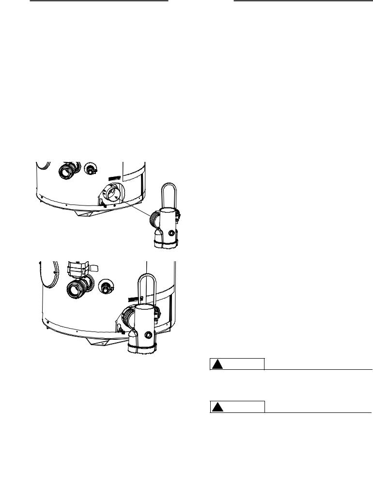
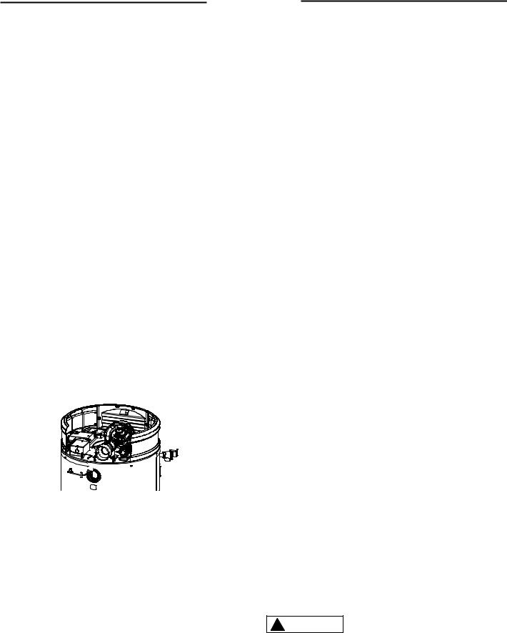
5.CONDENSATE
EXHAUST TEE & NEUTRALIZER - The exhaust
elbow/condensate trap is located in the installation kit along with the bag of neutralizer. Pour the neutralizer into the exhaust tee so that it is in the bottom. Then insert the exhaust tee onto the heater as shown in Figure 1. Using a 5/16" nut driver or ratchet, tighten the exhaust tee onto the heater.
CONDENSATE - This is a condensing high efficiency appliance and has a condensate removal system. The exhaust tee incorporates a condensate trap and must be filled with water before operating the water heater. Pour about 1 cup of water into the exhaust tee.
SERVICING - Remove the exhaust elbow from the heater using a 5/16" nut driver or ratchet. Empty the condensate and neutralizer from the exhaust elbow, and refill it with the new neutralizer (Rheem part number AP16770). Re-attach the exhaust tee to the heater. Pour approximately 1 cup of water into the exhaust tee. Re-attached the venting. It is very important that the condensate line is sloped away from the heater and down to a suitable inside drain. If the condensate outlet on this unit is lower than the drain, you must use a condensate removal pump. It is also important that the condensate line is not exposed to freezing temperatures, or any other type of blockage. Plastic tubing should be the only material used for the condensate line. Steel, brass, copper, or other metals will be subject to corrosion and deterioration, so they are not recommended to be used for the condensate drain line. A second vent may be necessary to prevent condensate line vacuum lock if a long horizontal run is used. Also an increase to 1" tubing may be necessary.
6.WIRING — A correct polarity 120V 50/60 Hz power supply with suitable disconnect means, must be connected to the black and white leads provided. The maximum current draw by these models is 7 Amps. The water heater, when installed, must be electrically grounded in accordance with local codes or, in the absence of local codes, with the National Electrical Code, ANSI/NFPA 70 in the
United States, or CSA C22.1 Electrical Code, in Canada. Improper grounding or polarity may result in abnormal operation of the unit. Refer on page 48 of this manual for the wiring diagram for this water heater.
! WARNING
The water heater must be vented to the outdoors as described in these instructions.
! WARNING
DO NOT connect this water heater to an existing vent or chimney; it must be vented separately from all other appliances, using only approved venting materials.
7
Installation
! WARNING
Failure to properly vent the water heater to the outdoors as outlined above and in the following section can result in unsafe operation of the water heater causing bodily injury, explosion, fire or death.
7. VENTING —
NOTE: This unit can be vented either as a direct vent or power vent configuration.
NOTICE: This unit can be vented using only the below recommended pipe material. Use only 2, 3, 4, or 6 inch diameter pipe.
! WARNING
NOTICE: DO NOT use in conjunction with a GFCI. To avoid the risk of fire, explosion or asphyxiation from carbon monoxide, NEVER operate this water heater unless it is properly vented and has an adequate air supply for proper operation. It is important that the vent pipe engages fully into any pipe fitting and be kept in that position until the adhesive has fully cured. DO NOT drill or punch holes in the plastic pipe or fittings.
Refer to local codes for restrictions on the use of PVC, CPVC, PP or ABS pipe and fittings. All exhaust venting materials for products installed in Canada must meet ULC-S636.
PVC (Schedule 40, ASTM D-1785)
CPVC (Schedule 40, ASTM F-441)
ABS (Schedule 40, ASTM D-2661)(Not permitted in Canada)
PVC Cellular Core (Schedule 40, ASTM F-891)(Not permitted in Canada)
The fittings, other than the VENT TERMINAL, should be equivalent to the following:
PVC (Schedule 40 DWV, ASTM D-2665)
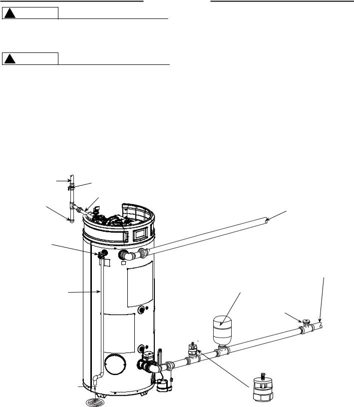
Figure 3. — Typical Installation Drawing.
To Gas Supply |
Manual Gas Shut Off |
|
Gas Pipe to Gas Valve
Sediment Trap
Hot Outlet
Temperature &
Pressure Relief
Valve
Discharge Line to suitable open drain
Thermal Expansion Tank |
Cold Water |
|
(Not Supplied) |
||
Inlet |
||
If required, install per local codes and |
||
|
||
tank manufacturer's instructions. |
|
|
Shut -Off Valve |
|
Vacuum Relief Valve
(Not Supplied)
Air Gap 6"
If required, install per local codes and valve manufacturer's instructions.
NOTES:
The gas supply piping must be adequately supported and aligned to minimize loads (forces) on the water heater’s gas valve and burner system.
8
Installation
CPVC (Schedule 40 DWV, ASTM F-438)
ABS (Schedule 40 DWV, ASTM D-2661)(Not permitted in Canada)
NOTICE: Use of PVC cellular core (ASTM-F891), ABS Schedule 40, DWV cellular core (ASTM –F628), or Radel® (polyphenylsulfone) in non-metallic venting systems is prohibited.
The unit may be vented horizontally through a wall or vertically through the roof. Pipe runs must be ad-
equately supported along both vertical and horizontal runs. Maximum unsupported span is recommended to be no more than 4 feet. It is imperative that the first hanger be located on the horizontal run immediately adjacent to the first 90-degree elbow from the vertical rise or at the blower outlet, in the case of a horizontal blower position. The support method used should isolate the vent pipe from floor joists or other structural members to help prevent the transmission of noise and vibration. DO NOT support, pin, or otherwise secure the venting system in a way that restricts the normal thermal expansion and contraction of the chosen venting material.
If the water heater is being installed as a replacement for an existing power vented water heater, a thorough inspection of the existing venting system must be performed prior to any installation work. Verify that the correct materials, as detailed above, have been used and that the minimum or maximum vent length and terminal locations, as detailed in this manual, have been met. Carefully inspect the entire venting system for any signs of cracks or fractures, particularly at the joints between elbows or other fittings and the straight runs of vent pipe. Check the system for signs of sagging or other stresses in the joints as a result of misalignment of any components in the system. If any of these conditions are found, they must be corrected in accordance with the venting instructions in this manual before completing the installation and putting the water heater into service.
Air Inlet 


Connection
Figure 4. — Vent Pipe Connection Locations
VENT PIPE CONNECTION —
Note: It is recommended that a suitable rubber coupling is used on the outlet vent connection.
Refer to Figure 4, for connecting the vent pipe to the water heater. These models can be vented either as a direct vent or as a power vent water heater.
NOTICE: If the unit is installed as a power vent water heater, the vent terminal with screen must still be installed on the inlet air side.
Before starting the vent installation, careful planning should be given to the routing and termination of the vent pipes. The length of the vent pipes (inlet and outlet) should be kept to a minimum. Also, see Figure 11 for vent terminal placement. Refer to the venting charts in Table 1 for the pipe sizes and the total equiv-
alent length of pipe that can be used. DO NOT exceed the equivalent length of pipe in the charts.
Depending on the size of pipe selected for venting the water heater, it may be necessary to use a fitting for stepping up or down in pipe size to connect to the water heater. All models are shipped with 3" vent terminals with screen. If another size of pipe is used for venting the unit, the proper vent
terminal must be installed.
When the unit is vented as a direct vent, through a side wall, the vent terminals must be on the same exterior wall mounted horizontally and maintain a minimum distance between the centers of 24" (61 cm). See Figures 8, 9, and 11 for other vent terminal restrictions.
JOINING PIPES AND FITTINGS – All pipe, fittings, solvent cement, primers, and procedures, must conform to American National Standards Institute and American Society for Testing and Materials (ANSI/ ASTM) standards in the U.S. For Canada, all pipe, fittings, solvent cement, primers, and procedures must conform to ULC-S636 and vent manufacture specifications.
CEMENTING JOINTS – All joints in the vent piping must be properly sealed. Use of the following material is recommended:
PVC materials should use ASTM D-2564 grade cement.
CPVC materials should use ASTM F-493 grade cement.
ABS materials should use ASTM D-2235 grade cement.
(ABS is not allowed in Canada)
Cleaner-Primer and Medium Body Solvent Cement
1.Cut the pipe end square, removing all jagged edges and burrs. Chamfer the end of the pipe, and, then, clean the fitting socket and pipe joint area to remove all dirt, grease, and moisture.
2.After checking pipe and socket for proper fit, wipe the socket and pipe with cleaner-primer. Apply a liberal coat of primer to the inside surface of the socket and the outside of the pipe. DO NOT allow the primer to dry before applying the cement.
3.Apply a thin coat of cement evenly in the socket. Quickly apply a heavy coat to the pipe end. Insert the pipe into the fitting with a slight twisting motion until it bottoms out.
NOTICE: Cement must be fluid; if not, re-coat.
4.Hold the pipe fitting for 30 seconds to prevent the tapered socket from pushing the pipe out of the fitting.
5.Wipe all excess cement from the joint with a rag. Allow 15 minutes for drying before handling. Cure time will vary according to fit, temperature, and humidity.
NOTICE: Stir the solvent cement frequently while using. Use a natural bristle brush or the dauber supplied with the can. The proper brush size is one inch.
FOR PROPER INSTALLATION:
!CAUTION
•DO NOT use solvent cement that has become curdled, lumpy or thickened.
•DO NOT thin solvent cement. Observe shelf precautions printed on the containers.
9
Installation
•For applications below 32°F (0°C), use only low temperature type solvent cement.
•Appropriate solvent and cleaner must be used for the type of vent pipe used (PVC, CPVC, PP, or ABS).
DANGER OF FIRE OR BODILY INJURY – Solvent cements and primers are highly flammable. Provide adequate ventilation and do not assemble near a heat source or open flame. DO NOT smoke. Avoid skin or eye contact. Observe all cautions and warnings on material containers.
DIRECT VENT INSTALLATION - Check to make sure flue gases DO NOT recirculate into the air intake terminal when using direct venting. If the water heater is having service issues, flue recirculation may be a contributing factor. Even when the minimum vent terminal separation distances are followed, recirculation may still occur, depending upon the location outside the building, the distance from other buildings, proximity to corners, weather conditions, wind patterns, and snow depth. Periodically check to make sure that flue recirculation is not occurring. Signs of flue gas recirculation include frosted or frozen
intake terminals, condensate in the intake terminal and venting system, oxidation, or white chalk material on the flame sensor or igniter shield. Correction to flue recirculation may involve angling the intake away from the exhaust terminal, increasing the distance
between them, or using inside air for combustion. Check to be sure the intake and exhaust terminals are not obstructed, especially during periods of below freezing weather.
All intake and exhaust venting components must have the same diameter size. DO NOT use a different size on the intake and exhaust venting.
Be sure the condensate runs freely to a drain and does not accumulate inside the water heater. In cold climates, precautions may need to be taken to insure that the condensate drain does not freeze. Make sure the condensate trap or drain loop is installed to prevent flue gases from being discharged into the room. Refer to the "Venting" section (page 8) of this manual for complete instructions on venting and condensate drainage.
Stress levels in the pipe and fittings can be significantly increased by improper installation. If rigid pipe clamps are used to hold the pipe in place, or if the pipe cannot move freely through a wall penetration, the pipe may be directly stressed, or high thermal stresses may be formed when the pipe heats up and expands. Install accordingly to minimize such stresses. Follow the below procedure to vent through the wall.
1.Cut two holes for the pipe to pass through. The hole diameter should be 2.5" (6.4 cm) for 2" pipe, 3.5" (8.9 cm) for 3" pipe, and 6.5" (16.5 cm) for 6" pipe. Vent terminals must maintain a horizontal distance apart in the range of 24" to 36" (61 cm to 91 cm). Refer to Figure 5 for additional information.
2.Use the proper PVC cement (primer and adhesive) to secure the exhaust vent and air intake terminals provided with the water heater to the plastic pipes. The distance between the back edge of the exhaust vent terminal and the exterior wall (see Figure 10) must be 6 inches (12.7 cm) more for the exhaust vent terminal than the air intake terminal. Use the proper cement or sealant and assembly procedures to secure the vent connector joints between the terminal and the blower outlet. Provide support brackets for every 3 feet (.91 m) of horizontal vent beyond the intake terminal as seen in Figure 10.
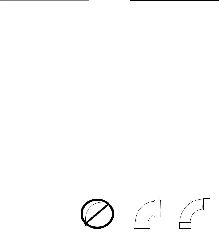
Additional Fitting Considerations
Figure - 5. Examples of Elbows: |
DO NOT use |
Good |
Best |
DO NOT use short sweep elbows. It is recommended to use only standard and/or long sweep elbows. See examples as shown.
Short Sweep 90° |
Standard 90° |
Long Sweep 90° |
Elbow |
Elbow |
Elbow |
10
Installation
MINIMUM AND MAXIMUM VENT LENGTHS
Important information for all installations:
1)The minimum required venting is what is required to safely extend the inlet and outlet vent pipes outside of the building.
2)Each 90° elbow (standard or long sweep elbow) reduces the equivalent vent length by 5 feet (1.5m).
3)Each 45° elbow reduces the equivalent vent length by 2 1/2 feet (0.8m).
4)DO NOT mix pipe sizes for venting these models, use only one size of pipe for all venting.
5)All vent terminations (horizontal or vertical) should be a minimum of 24 inches (61cm) and a maximum of 36 inches (91 cm) apart, as measured from center to center of terminals.
6)The maximum equivalent vent lengths, for inlet and outlet, must be within 20 equivalent feet (6.1m) of each other. Supplied vent terminal(s) are not included in the maximum equivalent vent length.
Feet to |
Meters |
20 |
6.1 |
50 |
15.2 |
60 |
18.3 |
70 |
21.3 |
80 |
24.4 |
100 |
30.5 |
120 |
36.6 |
130 |
39.6 |
170 |
51.8 |
Exceeding the maximum equivalent vent lengths may cause the water heater to malfunction or cause a lock-out condition.
Power Vent |
|
|
Max Vent Length (Eq.Ft.) |
|
|
|||||
|
|
Rigid Pipe Diameter |
|
|
||||||
|
|
|
|
|
|
|||||
Inlet Models |
Altitude |
2" (5 cm) |
3" (8 cm) |
4" (10 cm) |
6" (15 cm) |
|||||
Range |
Inlet |
Outlet |
Inlet |
Outlet |
Inlet |
Outlet |
Inlet |
Outlet |
||
|
||||||||||
GHE80SU-130(A) |
0-8999 Ft |
1 |
35 |
1 |
135 |
1 |
185 |
|
|
|
or |
N/A |
N/A |
||||||||
(0-2743 m) |
(0.31 m) |
(10.7 m) |
(0.31 m) |
(41.1 m) |
(0.31 m) |
(56.4 m) |
||||
GHE80SU-160(A) |
|
|
||||||||
|
|
|
|
|
|
|
|
|
||
|
|
|
|
|
|
|
|
|
|
|
GHE80SU-200(A) |
0-8000 ft |
1 |
35 |
1 |
135 |
1 |
185 |
N/A |
N/A |
|
(0-2438 m) |
(0.31 m) |
(10.7 m) |
(0.31 m) |
(41.1 m) |
(0.31 m) |
(56.4 m) |
||||
|
|
|
||||||||
GHE80SU-300(A) |
0-8000 Ft |
1 |
35 |
1 |
135 |
1 |
185 |
1 |
120 |
|
(0-2438 m) |
(0.31 m) |
(10.7 m) |
(0.31 m) |
(41.1 m) |
(0.31 m) |
(56.4 m) |
(0.31 m) |
(36.6 m) |
||
|
||||||||||
|
|
|
|
|
|
|
|
|
|
|
GHE100SU-130(A) |
0-8999 ft |
1 |
35 |
1 |
135 |
1 |
185 |
|
|
|
or |
N/A |
N/A |
||||||||
(0-2743 m) |
(0.31 m) |
(10.7 m) |
(0.31 m) |
(41.1 m) |
(0.31 m) |
(56.4 m) |
||||
GHE100SU-160(A) |
|
|
||||||||
|
|
|
|
|
|
|
|
|
||
|
|
|
|
|
|
|
|
|
|
|
GH100SU-200(A) |
0-8999 ft |
1 |
35 |
1 |
135 |
1 |
185 |
N/A |
N/A |
|
(0-2743 m) |
(0.31 m) |
(10.7 m) |
(0.31 m) |
(41.1 m) |
(0.31 m) |
(56.4 m) |
||||
|
|
|
||||||||
|
|
|
|
|
|
|
|
|
|
|
GHE100SU-250(A) |
0-8999 ft |
1 |
35 |
1 |
135 |
1 |
185 |
1 |
120 |
|
or |
||||||||||
(0-2743 m) |
(0.31 m) |
(10.7 m) |
(0.31 m) |
(41.1 m) |
(0.31 m) |
(56.4 m) |
(0.31 m) |
(36.6 m) |
||
GHE100SU-300(A) |
||||||||||
|
|
|
|
|
|
|
|
|
||
|
|
|
|
|
|
|
|
|
|
|
GHE100SU-350(A) |
0-8999 ft |
|
|
1 |
65 |
1 |
100 |
1 |
135 |
|
or |
N/A |
N/A |
||||||||
(0-2743 m) |
(0.31 m) |
(19.8 m) |
(0.31 m) |
(30.5 m) |
(0.31 m) |
(41.1 m) |
||||
GHE100SU-400(A) |
|
|
||||||||
|
|
|
|
|
|
|
|
|
||
|
|
|
|
|
|
|
|
|
|
|
|
|
|
|
Min Vent Length (Eq.Ft.) |
|
|
||||
|
|
|
|
Rigid Pipe Diameter |
|
|
||||
All Models |
See Below |
1 |
15 |
1 |
15 |
1 |
15 |
1 |
15 |
|
(0.31 m) |
(4.6 m) |
(0.31 m) |
(4.6 m) |
(0.31 m) |
(4.6 m) |
(0.31 m) |
(4.6 m) |
|||
|
|
|||||||||
|
|
|
|
|
|
|
|
|
|
|
TABLE 1. POWER VENTING – RIGID VENT PIPING: PVC, CPVC, ABS, PP – MAX VENT LENGTHS
Models GHE80SU-200(A) & GHE80SU-300(A) are limited to an altitude of 8000 ft, while all other models are limited to 8999 ft.
11

Installation
Power Direct Vent |
|
|
Max Vent Length (Eq.Ft.) |
|
|
|||||
|
|
Rigid Pipe Diameter |
|
|
||||||
|
|
|
|
|
|
|||||
Inlet Models |
Altitude |
2" (5 cm) |
3" (8 cm) |
4" (10 cm) |
6" (15 cm) |
|||||
Range |
Inlet |
Outlet |
Inlet |
Outlet |
Inlet |
Outlet |
Inlet |
Outlet |
||
|
||||||||||
GHE80SU-130(A) |
0-2000 |
20 |
35 |
60 |
75 |
120 |
135 |
N/A |
N/A |
|
(0 - 609 m) |
(6.1 m) |
(10.7 m) |
(18.3 m) |
(22.9 m) |
(36.6 m) |
(41.1 m) |
||||
or |
|
|
||||||||
|
|
|
|
|
|
|
|
|
||
2001-8999 |
20 |
35 |
40 |
55 |
120 |
135 |
|
|
||
GHE80SU-160(A) |
N/A |
N/A |
||||||||
(610 - 2743 m) |
(6.1 m) |
(10.7 m) |
(12.2 m) |
(16.8 m) |
(36.6 m) |
(41.1 m) |
||||
|
|
|
||||||||
|
|
|
|
|
|
|
|
|
|
|
GH80SU-200(A) |
0-8000 ft |
20 |
35 |
60 |
75 |
120 |
135 |
120 |
135 |
|
or |
||||||||||
(0-2438 m) |
(6.1 m) |
(10.7 m) |
(18.3 m) |
(22.9 m) |
(36.6 m) |
(41.1 m) |
(36.6 m) |
(41.1 m) |
||
GHE80SU-300(A) |
||||||||||
|
|
|
|
|
|
|
|
|
||
|
|
|
|
|
|
|
|
|
|
|
GHE100SU-130(A) |
0-2000 |
20 |
35 |
60 |
75 |
120 |
135 |
N/A |
N/A |
|
(0 - 609 m) |
(6.1 m) |
(10.7 m) |
(18.3 m) |
(22.9 m) |
(36.6 m) |
(41.1 m) |
||||
or |
|
|
||||||||
|
|
|
|
|
|
|
|
|
||
2001-8999 |
20 |
35 |
40 |
55 |
120 |
135 |
|
|
||
GHE100SU-160(A) |
N/A |
N/A |
||||||||
(610 - 2743 m) |
(6.1 m) |
(10.7 m) |
(12.2 m) |
(16.8 m) |
(36.6 m) |
(41.1 m) |
||||
|
|
|
||||||||
GH100SU-200(A) |
0-2000 |
20 |
35 |
60 |
75 |
120 |
135 |
N/A |
N/A |
|
or |
(0 - 609 m) |
(6.1 m) |
(10.7 m) |
(18.3 m) |
(22.9 m) |
(36.6 m) |
(41.1 m) |
|||
|
|
|||||||||
GHE100SU-250(A) |
|
|
|
|
|
|
|
|
|
|
2001-8999 |
20 |
35 |
40 |
55 |
120 |
135 |
120 |
135 |
||
or |
||||||||||
GHE100SU-300(A) |
(610 - 2743 m) |
(6.1 m) |
(10.7 m) |
(12.2 m) |
(16.8 m) |
(36.6 m) |
(41.1 m) |
(36.6 m) |
(41.1 m) |
|
|
|
|
|
|
|
|
|
|
|
|
GHE100SU-350(A) |
0-8999 ft |
|
|
50 |
65 |
70 |
85 |
120 |
135 |
|
or |
N/A |
N/A |
||||||||
(0 - 2743 m) |
(15.2 m) |
(19.8 m) |
(21.4 m) |
(25.9 m) |
(36.6 m) |
(41.1 m) |
||||
GHE100SU-400(A) |
|
|
||||||||
|
|
|
|
|
|
|
|
|
||
|
|
|
|
|
|
|
|
|
|
|
|
|
|
|
Min Vent Length (Eq.Ft.) |
|
|
||||
|
|
|
|
Rigid Pipe Diameter |
|
|
||||
All Models |
See Below |
5 |
15 |
5 |
15 |
5 |
15 |
5 |
15 |
|
(1.5 m) |
(15.2 m) |
(1.5 m) |
(15.2 m) |
(1.5 m) |
(15.2 m) |
(1.5 m) |
(15.2 m |
|||
|
|
|||||||||
TABLE 2. POWER DIRECT VENTING LENGTHS
Models GHE80SU-200(A) & GHE80SU-300(A) are limited to an altitude of 8000 ft, while all other models are limited to 8999 ft.
For each 90° Elbow, reduce pipe length by five (5) feet.
For each 45° Elbow, reduce pipe length by two and a half (2.5) feet.
Note: Vent pipe size should not be mixed for venting these units.
Use same diameter pipe for all venting of the unit.
Venting Configurations are the Same for SS Models:
All power direct vent models can use 3 in. or 4 in. concentric venting the above vent lengths. 3 inch concentric vent can only be used with 3 inch rigid piping.
4 inch concentric vent can only be used with 3 inch rigid piping.
DO NOT mismatch concentric vent terminations with different rigid piping as it may cause the heater to malfunction or cause a lock-out condition.
DO NOT use 2 inch rigid venting with concentric vent terminations. DO NOT use 6 inch rigid venting with concentric vent terminations.
Flexible Polypropylene pipe (ft)
Pipe Size (IN.) |
3 |
|
|
4 |
||
|
|
|
|
|
|
|
|
Intake |
|
Exhaust |
Intake |
|
Exhaust |
|
|
|
|
|
|
|
Max PV |
0 |
|
60 |
0 |
|
60 |
|
|
|
|
|
|
|
Models GHE80SU-200(A) & GHE80SU-300(A) are limited to an altitude of 8000 ft, while all other models are limited to 8999 ft.
12
|
|
Installation |
|
||
|
|
|
vent terminal is at least 2 feet (0.61 m) away from any- |
||
|
|
|
thing that can be damaged by the condensate |
||
|
|
|
HORIZONTAL VENT INSTALLATION – Once the vent terminal |
||
|
Min. 24" |
location has been determined, make a hole through the |
|||
|
Max. 36" |
exterior wall to accommodate the vent pipe. The vent |
|||
|
|
|
pipe must exit the exterior wall horizontally only (See |
||
|
|
|
Figure 6). |
|
|
|
|
|
Insert a small length of vent pipe through the wall, and |
||
|
|
|
connect the coupling as shown in Figure 6. Connect the |
||
|
|
|
vent terminal as shown to the vent pipe on the exterior |
||
|
|
|
of the building. Seal any opening around the vent pipe or |
||
|
Inlet |
Outlet |
fittings with mortar or silicone caulk as shown in Figure |
||
|
|
|
6. |
|
|
Figure 5 |
|
|
Complete the rest of the vent pipe installation to the |
||
|
|
water heater’s vent connector fitting on the blower |
|||
|
|
|
|||
|
|
Sheet Metal Shield on |
outlet. If necessary, support the horizontal run of pipe |
||
|
|
Brick or Masonry Walls |
as previously mentioned. |
||
Vent Pipe |
|
Elbow can be a maximum |
|
Short Piece of Vent |
|
|
of 1 inch from the wall. |
|
|||
|
|
|
Pipe |
||
|
|
|
|
||
Pipe & |
Vent |
Inlet Vent Terminal |
|
|
|
Coupling |
Pipe |
with 1/2" Mesh Pro- |
|
|
|
|
|
tective |
|
|
|
|
|
Screen Inside |
|
|
|
To the Water Heater |
|
|
*Min. 12"(30.5 CM) Above |
Vent Pipe |
|
|
|
Through Roof |
|||
|
|
Outside of the |
Roof or |
|
|
|
|
Min. 12"(30.5 CM) Above |
|
||
|
|
Building Wall |
|
||
|
|
Anticipated Snow Level. |
|
||
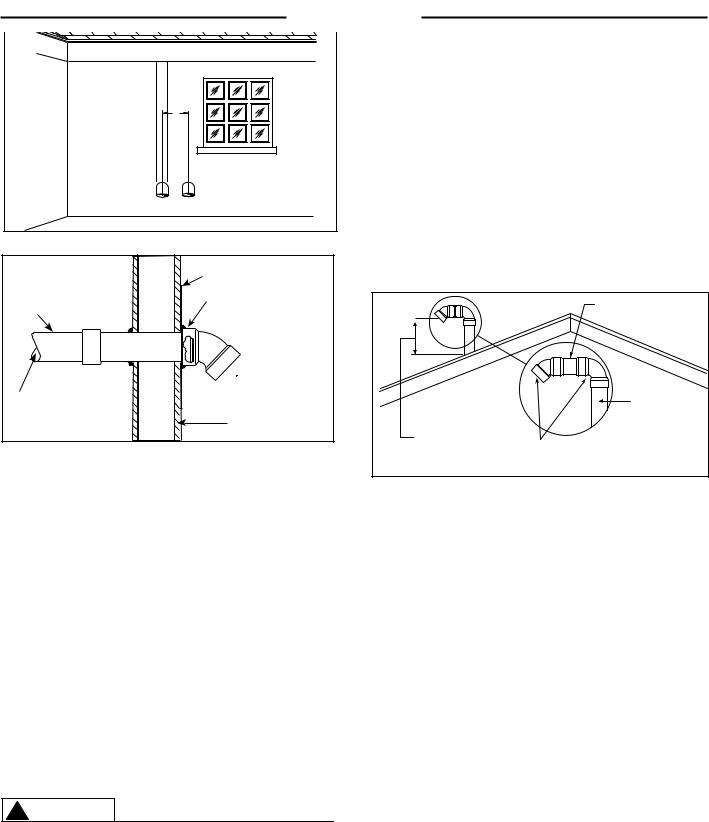
Figure 6 – Typical Horizontal Vent Installation |
Max. 24"(61 cm) Above |
Elbows |
|||
* Min of 18"(46cm) for Canada |
|||||
Additional Considerations (See Figures 10 & 11) |
Roof (Without Additional |
||||
Support) |
|
||||
1.DO NOT install vent terminals under any patio or deck.
2.To help prevent moisture from freezing on walls and under eaves, DO NOT locate outlet vent terminal on the side of a building with prevailing winter winds.
3.DO NOT terminate vent pipe directly on brick or masonry surfaces. Use a rust-resistant sheet metal backing plate behind vent. (See Figure 6.)
4.DO NOT locate vent terminal too close to shrubbery, since flue gases may damage them.
5.Caulk all cracks, seams and joints within 6 feet (1.83 m) of vent terminal.
6.All painted surfaces should be primed to lessen the chance of physical damage. Painted surfaces will require maintenance.
7.Make sure that all vent pipes exposed to cold conditions (attics, crawl spaces, etc.) have the proper slope and support to keep moisture from accumulating in the vent pipes. NOTE: Insulating of non-metallic vent materials is prohibited.
8.This water heater requires its own separate venting system. DO NOT connect the exhaust vent to an existing vent pipe or chimney.
! WARNING
Moisture in the flue gas will condense as it leaves the vent terminal. In cold weather this condensate can freeze on the exterior wall, under the eaves, and on surrounding objects. Some discoloration to the exterior of the building is to be expected; however, improper location or installation can result in severe damage to the structure or exterior finish of the building. In locations with extended amounts of time with temperatures under 40°F. (4°C.) and/or prevailing wind toward the outlet vent, make sure that the outlet
Figure 7 – Vertical Vent Terminal Location
VERTICAL VENT INSTALLATION – Once the vent terminal location has been determined, make a hole through the roof and interior ceiling to accommodate the vent pipe. Complete the vent pipe installation to the water heater’s vent connector fitting on the blower outlet. Support vertical or horizontal runs as previously mentioned.
Install adequate flashing where the vent pipe passes through the roof. Determine the vent terminal height and cut the vent pipe accordingly. Refer to Figure 9 for the proper vent terminal height. Connect the vent elbow onto the vertical pipe through the roof. Connect a short piece of vent pipe (approximately 3" (7.6 cm) long) to the elbow, and, then, join the vent terminal to the short piece of vent pipe.
VERTICAL VENT TERMINAL LOCATION – The location of the vertical vent terminal depends on the following considerations (see Figure 7):
1.Minimum 12" (30.5 cm) above the roof 18" (46 cm) for Canada.
2.Minimum 12" (30.5 cm) inches above anticipated snow level.
3.Maximum 24" (61 cm) above roof level without additional support for vent pipe.
4.4 feet (1.22 m) from any gable, dormer or other roof structure with building interior access (i.e., vent, window, etc.).
5.10 feet (3.05 m) from any forced air inlet to the building. Any fresh or make-up air inlet such as a dryer or furnace area is considered to be a forced air inlet.
6.Vent terminals are a minimum of 24" (61 cm) and a maximum of 36" horizontally apart.
13
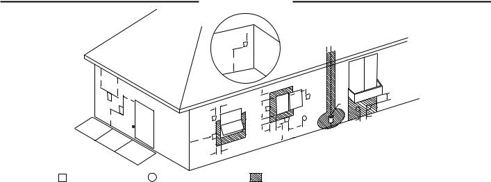
Figure 8
Installation
G
D
|
E |
V |
B |
|
|
|
V |
L |
|
F
v
A
|
C |
|
v |
FIXED |
|
OSED |
||
|
CL |
|
|
|
E |
|
|
ABL |
|
ER |
|
|
OP |
|
v |
|
|
|
B |
|
 H
H
|
|
|
|
C |
|
|
|
M |
|
|
|
|
v |
|
|
|
|
B |
|
|
|
D |
|
|
|
|
|
|
|
FIXEED |
|
|
|
|
|
|
|
|
BLE |
OS |
|
|
|
|
|
|
|
CL |
|
|
|
|
|
|
|
RA |
|
|
I |
|
|
|
|
v |
OPE |
|
|
|
|
v |
|
|
|
|
|
|
|
X |
||
|
|
|
|
|
|
|
||
B |
|
|
v |
|
X |
|
|
K |
|
|
|
|
|
|
|
|
|
|
B |
A |
J |
|
|
|
|
|
|
|
|
|
|
|
|||
|
|
|
|
|
|
|
||
V VENT TERMINAL |
X AIR SUPPLY INLET |
AREA WHERE TERMINAL IS NOT PERMITTED |
Horizontal Vent Terminal Location for Power Direct Vent |
||
The following information should be used for determining the proper location of the vent terminal
for direct vent water heaters. |
Canadian Installations 1 |
US Installations 2 |
||
|
|
|
||
|
A= |
Clearance above grade, veranda, |
12 inches (30 cm) |
12 inches (30 cm) |
|
|
porch, deck or balcony. |
|
|
|
|
|
|
|
|
B= |
Clearance to window or door that may |
6 inches (15 cm) for appliances < 10,000 |
6 inches (15 cm) for appliances.< 10,000 |
|
|
be opened. |
Btuh (3 kW), 12 inches (30 cm) for |
Btuh (3 kW), 9 inches (23 cm) for |
|
|
|
appliances > 10,000 Btuh (3kW) and |
appliances > 10,000 Buth (3 kW) and |
|
|
|
< 100,000 Btuh (30kW), 36 inches (91 cm) |
< 50,000 Btuh (15 kW), 12 inches (30 cm) |
|
|
|
for appliances > 100,000 Btuh (30kW). |
for appliances > 50,000 Btuh (15 kW) |
|
|
|
|
|
|
C= Clearance to permanently closed |
* |
* |
|
|
window. |
|
|
|
|
|
|
|
|
|
D= |
Vertical Clearance to ventilated soffit |
* |
* |
|
|
located above the terminal within a |
|
|
|
|
horizontal distance of 2 feet (61 cm) |
|
|
|
|
from the center line of the terminal. |
|
|
|
|
|
|
|
|
E= |
Clearance to unventilated soffit. |
* |
* |
|
|
|
|
|
|
F= |
Clearance to outside corner. |
* |
* |
|
|
|
|
|
|
G= |
Clearance to inside corner. |
* |
* |
|
|
|
|
|
|
H = Clearance to each side of center line |
3 feet (91 cm) within a height 15 feet (4.57 |
* |
|
|
|
extended meter/regulator assembly. |
m) above the meter/regulator assembly. |
|
|
|
above |
|
|
|
|
|
|
|
|
I = |
Clearance to service regulator vent |
3 feet (91 cm) |
* |
|
|
outlet. |
|
|
|
J = |
Clearance to nonmechanical air supply |
6 inches (15 cm) for appliances < 10,000 |
6 inches (15 cm) for appliances.< 10,000 |
|
|
inlet to the building or the combustion |
Btuh (3 kW), 12 inches (30 cm) for |
Btuh (3 kW), 9 inches (23 cm) for |
|
|
air inlet of any other appliance.. |
appliances > 10,000 Btuh (3kW) and |
appliances > 10,000 Buth (3 kW) and |
|
|
|
< 100,000 Btuh (30kW), 36 inches (91 cm) |
< 50,000 Btuh (15 kW), 12 inches (30 cm) |
|
|
|
for appliances > 100,000 Btuh (30kW). |
for appliances > 50,000 Btuh (15 kW) |
|
|
|
|
|
|
K = |
Clearance to mechanical air supply |
6 feet (1.83 m) |
3 feet (91 cm) above if within 10 feet(3 m) |
|
|
|||
|
|
inlet. |
|
horizontally. |
|
|
|
|
|
|
L = |
Clearance above paved side walk or |
7 feet (2.13 m)+ |
7 feet (2.13 m)+ |
|
|
paved driveway located on public |
|
|
|
|
property. |
|
|
|
M = Clearance under veranda, porch, deck |
Not Allowed |
Not Allowed |
|
|
|
or balcony. |
|
|
|
|
|
|
|
1 In accordance with current CAN/CSA-B149.1 Installation Codes.
2 In accordance with current ANSI Z223.1/ NFPA 54 National Fuel Gas Code.
+A vent shall not terminate directly above a sidewalk or paved driveway that is located between two single family dwellings and serves both dwellings.
*"Clearance in accordance with local installation codes and the requirements of the gas supplier."
14

Installation
•DO NOT terminate near soffit vents or crawl space or other area where condensate or vapor could create a nuisance hazard or cause property damage.
•DO NOT locate the exhaust vent terminal where condensate or vapor could cause damage or could be detrimental to the operation of regulators, relief valves, or other equipment.
•DO NOT locate the exhaust vent terminal over public area or walkways where condensate or vapor can cause nui sance or hazard.
•DO NOT locate the vent terminal in proximity to plants/shrubs.
VENT INSTALLATION – Before proceeding, make certain you understand the procedure and cautions covered in the section “Joining Pipes and Fittings.”
POWER VENT INSTALLATION:
Power venting is where the indoor air is used and the exhaust is vented to the outside. Venting may be run horizontally through an outside wall or vertically through a roof through using either 2" (5.1 cm), 3" (7.6 cm), 4" (10.2 cm) or 6" (15.2 cm) diameter PVC, ABS or CPVC. This water heater is supplied with a screened intake elbow and exhaust coupling referred to as the air intake terminal and the exhaust vent terminal.
NOTE:
Flexible PP vent kit is available for Power Vent configurations, in either 3" or 4" diameters. These kits should be used for vertical venting only.
NOTICE: Use of PVC cellular core (ASTM-F891), ABS Schedule 40, DWV cellular core (ASTM –F628), or Radel® (polyphenylsulfone) in non-metallic venting systems is prohibited.
In a horizontal application, it is important that condensate not be allowed to buildup in the exhaust vent pipe. To prevent this from happening, the pipe should be installed with a slight upward slope of ¼” per foot. The vent system must be supported every 5 feet of vertical run and every 3 feet of horizontal run of vent pipe length.
Failure to properly support the vent piping with hangers and clamps may result in damage to the water heater or venting system.
15

Installation
Figure 9
D
|
E |
V |
B |
|
|
|
V |
L |
|
F
G
v
A
|
C |
|
|
|
|
|
ED |
|
|
v |
FIX |
ED |
|
|
|
OS |
|
||
|
CL |
|
|
|
|
|
|
|
E |
|
|
|
BL |
|
|
ERA |
|
||
|
OP |
|
|
|
v |
|
|
|
|
|
B |
|
|
|
|
|
|
C |
v |
B |
|
|
D |
|
|
|
FIXE |
|
|
|
|
E |
CLOSED |
|
|
|
RABL |
|
|
|
|
OPE |
|
|
|
v |
|
|
|
B |
|
v |
|
X |
|
|
|
||
|
|
|
|
|
|
B |
A |
J |
|
|
|
|
||
|
|
|
|
 H
H
I
M
X |
v |
|
|
|
K |
V VENT TERMINAL |
X AIR SUPPLY INLET |
AREA WHERE TERMINAL IS NOT PERMITTED |
Horizontal Vent Terminal Location for Power Vent |
||
The following information should be used for determining the proper location of the vent terminal for
direct vent water heaters. |
Canadian Installations 1 |
US Installations 2 |
||
|
|
|
||
|
A= Clearance above grade, veranda, |
12 inches (30 cm) |
12 inches (30 cm) |
|
|
|
porch, deck or balcony. |
|
|
|
|
|
|
|
|
B= |
Clearance to window or door that may |
6 inches (15 cm) for appliances < 10,000 |
4 feet (1.2 m) below or to side of opening; |
|
|
be opened. |
Btuh (3 kW), 12 inches (30 cm) for |
1 foot (300 mm) above opening. |
|
|
|
appliances > 10,000 Btuh (3kW) and |
|
|
|
|
< 100,000 Btuh (30kW), 36 inches (91 cm) |
|
|
|
|
for appliances > 100,000 Btuh (30kW). |
|
|
|
|
|
|
|
C= Clearance to permanently closed |
* |
* |
|
|
window. |
|
|
|
|
|
|
|
|
|
D= |
Vertical Clearance to ventilated soffit |
* |
* |
|
|
located above the terminal within a |
|
|
|
|
horizontal distance of 2 feet (61 cm) |
|
|
|
|
from the center line of the terminal. |
|
|
|
|
|
|
|
|
E= |
Clearance to unventilated soffit. |
* |
* |
|
|
|
|
|
|
F= |
Clearance to outside corner. |
* |
* |
|
|
|
|
|
|
G= |
Clearance to inside corner. |
* |
* |
|
|
|
|
|
|
H = Clearance to each side of center line |
3 feet (91 cm) within a height 15 feet (4.57 |
* |
|
|
|
extended meter/regulator assembly. |
m) above the meter/regulator assembly. |
|
|
|
above |
|
|
|
|
|
|
|
|
I = |
Clearance to service regulator vent |
3 feet (91 cm) |
* |
|
|
outlet. |
|
|
|
J = |
Clearance to nonmechanical air supply |
6 inches (15 cm) for appliances < 10,000 |
4 feet (1.2 m) below or to side of opening; |
|
|
inlet to building or the combustion air |
Btuh (3 kW), 12 inches (30 cm) for |
1 foot (300 m) above opening. |
|
|
inlet to any other appliance.. |
appliances > 10,000 Btuh (3kW) and |
|
|
|
|
< 100,000 Btuh (30kW), 36 inches (91 cm) |
|
|
|
|
for appliances > 100,000 Btuh (30kW). |
|
|
|
|
|
|
|
K = |
Clearance to mechanical air supply |
6 feet (1.83 m) |
3 feet (91 cm) above if within 10 feet (3 m) |
|
|
|||
|
|
inlet. |
|
horizontally. |
|
|
|
|
|
|
L = |
Clearance above paved side walk or |
7 feet (2.13 m)+ |
7 feet (2.13 m)+ |
|
|
paved driveway located on public |
|
|
|
|
property. |
|
|
|
M = Clearance under veranda, porch, deck |
Not Allowed |
Not Allowed |
|
|
|
or balcony. |
|
|
|
|
|
|
|
1 In accordance with current CAN/CSA-B149.1 Installation Codes.
2 In accordance with current ANSI Z223.1/ NFPA 54 National Fuel Gas Code.
+A vent shall not terminate directly above a sidewalk or paved driveway that is located between two single family dwellings and serves both dwellings.
* "Clearance in accordance with local installation codes and the requirements of the gas supplier."
16
 Loading...