


 WARNING:
RECOGNIZE THIS SYMBOL AS AN INDICATION OF IMPORTANT SAFETY INFORMATION
 WARNING
THESE INSTRUCTIONS ARE INTENDED AS AN AID TO QUALIFIED, LICENSED SERVICE PERSONNEL FOR PROPER INSTALLATION, ADJUSTMENT, AND OPERATION OF THIS UNIT.
READ THESE INSTRUCTIONS THOROUGHLY BEFORE ATTEMPTING INSTALLATION OR OPERATION. FAILURE TO FOLLOW THESE INSTRUCTIONS MAY RESULT IN IMPROPER INSTALLATION, ADJUSTMENT, SERVICE,
OR MAINTENANCE POSSIBLY RESULTING IN FIRE, ELECTRICAL SHOCK, PROPERTY DAMAGE, PERSONAL INJURY, OR DEATH.
Do not destroy this manual. Please read carefully and keep in a safe place for future reference by a serviceman.
VARIABLE SPEED R-410A
HEAT PUMP/ AIR CONDITIONING OUTDOOR UNITS


 Enabled
INSTALLATION INSTRUCTIONS
(-)A15AZ(-)P16AZ/(-)A16AZ (15/16 SEER2) EQUIPPED WITH ECONET™ COMMUNICATIONS
[ ] indicates metric conversions.
92-104921-25-04( / ) |
Printed in the USA |
ISO 9001:2015 |
|
|

<![endif]>Contents
CONTENTS |
|
|
1.0 IMPORTANT SAFETY INFORMATION............................................................. |
3 |
|
2.0 GENERAL INFORMATION................................................................................ |
4 |
|
2.1 Introduction..................................................................................................... |
4 |
|
2.2 |
Agency Performance Audit Testing Notice.................................................... |
4 |
2.3 |
Importance of Quality Installation.................................................................. |
4 |
2.4 |
System Sizing and Selection.......................................................................... |
4 |
2.5 |
Importance of Proper Indoor/Outdoor Match-Ups......................................... |
5 |
2.6 |
Checking Product Received........................................................................... |
5 |
2.7 Compressor Break-In Notice........................................................................ |
5 |
|
2.0 GENERAL INFORMATION................................................................................ |
5 |
|
3.0 UNIT SPECIFICATIONS..................................................................................... |
6 |
|
3.1 Model Number Nomenclature and Available Models..................................... |
6 |
|
3.2 |
Electrical and Physical Data.......................................................................... |
7 |
4.0 INSTALLATION.................................................................................................. |
8 |
|
4.1 Tools and Refrigerant..................................................................................... |
8 |
|
|
4.1.1 Tools Required for Installing and Servicing R-410A Models................. |
8 |
|
4.1.2 Specifications of R-410A........................................................................ |
8 |
|
4.1.3 Quick-Reference Guide for R-410A....................................................... |
8 |
4.2 |
Choosing a Location....................................................................................... |
9 |
|
4.2.1 Allowable Clearances............................................................................ |
9 |
|
4.2.2 Operational Issues Related to Unit Location........................................ |
9 |
|
4.2.3 Corrosive Environment........................................................................ |
10 |
|
4.2.4 Customer Satisfaction Issues.............................................................. |
10 |
4.3 |
Unit Mounting............................................................................................... |
10 |
|
4.3.1 Unit Mounting Methods........................................................................ |
10 |
|
4.3.2 High Wind and Seismic Tie-Down Methods....................................... |
10 |
4.2 |
Choosing a Location (cont.)......................................................................... |
10 |
4.3.3 Elevating Unit............................................................................................ |
11 |
|
|
4.4.1 Replacing Existing Systems................................................................. |
12 |
|
4.4.2 Line Set Application Considerations................................................... |
12 |
|
4.4.2.1 Oil Return to Compressor............................................................... |
12 |
|
4.4.2.2 Refrigerant Migration During Off Cycle........................................ |
12 |
|
4.4.2.3 Maximum Liquid Pressure Drop.................................................... |
12 |
|
4.4.2.4 Liquid Line Refrigerant Flashing................................................... |
12 |
4.4 |
Refrigerant Line Set Selection..................................................................... |
12 |
|
4.4.2.5 Oil Level Adjustment for Long Line Set Applications.................... |
13 |
|
4.4.2.6 Capacity Losses............................................................................ |
13 |
|
4.4.3 Line Set Length and Fitting Losses..................................................... |
13 |
|
4.4.4 Liquid Line Selection............................................................................ |
14 |
|
4.4.5 Vapor Line Selection............................................................................ |
14 |
4.5 |
Line Set Installation...................................................................................... |
17 |
|
4.5.1 Important Tubing Installation Practices............................................... |
17 |
|
4.5.2 Relative Location of Indoor and Outdoor Units................................... |
18 |
|
4.5.2.1 Outdoor Unit Level or Near Level to Indoor Coil Line Set............. |
18 |
4.5 |
Line Set Installation (cont.)........................................................................... |
18 |
|
4.5.2.2 Outdoor Unit Below Indoor Coil (Long Line Set Applications)..... |
19 |
|
4.5.2.3 Outdoor Unit Above Indoor Coil.................................................... |
20 |
|
4.5.3 Tubing Connections............................................................................. |
21 |
4.6 |
Initial Leak Testing ....................................................................................... |
22 |
4.7 Evacuation ................................................................................................... |
22 |
|
4.8 |
Final Leak Testing........................................................................................ |
23 |
4.9 |
Control Wiring............................................................................................... |
23 |
|
4.9.1 EcoNet™ Communications................................................................... |
23 |
|
4.9.2 EcoNet™ Control Center Installation.................................................... |
23 |
|
4.9.3 EcoNet™ Communication Wiring Connections.................................... |
23 |
|
4.9.4 Conventional 24VAC Thermostat Control Wiring Connections.......... |
24 |
|
4.9.5 For Installations with Only 2 Thermostat Wires................................... |
25 |
4.9 |
Control Wiring (cont.).................................................................................... |
26 |
4.10 Power Wiring............................................................................................... |
27 |
|
4.11 Grounding....................................................................................................... |
27 |
|
5.0 SYSTEM START-UP AND REFRIGERANT CHARGING............................... |
28 |
|
5.1 System Start-Up Overview........................................................................... |
28 |
|
5.2 |
Initial Power-Up............................................................................................ |
28 |
and EcoNet™ Communication Verification......................................................... |
28 |
|
5.3 |
EcoNet™ Control Center Set-Up................................................................... |
28 |
5.4 |
Initial System................................................................................................ |
27 |
Start-Up.............................................................................................................. |
27 |
|
5.5 |
Entering Charge Mode Using EcoNet™ Control Center Service Menu....... |
29 |
5.6 |
Entering Charge Mode When Using a Universal Outdoor Control.............. |
29 |
5.7 Indoor Air-Flow Verification ......................................................................... |
30 |
|
5.8 |
Refrigerant Charging.................................................................................... |
30 |
|
5.8.1 Measurement Device Set-Up............................................................... |
31 |
|
5.8.2 Preliminary Charging by Weight.......................................................... |
31 |
|
5.8.3 Preliminary Charging by Pressures (Optional).................................... |
31 |
|
5.8.4 Final Charging by Liquid Subcooling................................................... |
30 |
|
5.8.5 R-410A Temperature Pressure Chart.................................................. |
30 |
5.9 |
Completing Installation ................................................................................ |
30 |
6.0 NORMAL SEQUENCE OF OPERATION........................................................ |
33 |
|
6.1 Cooling Mode................................................................................................ |
33 |
|
6.2 |
On-Demand Cooling Dehumidification........................................................ |
33 |
6.3 |
Low Ambient Cooling Mode......................................................................... |
33 |
6.4 Supplemental Electric Heat in Heating Mode................................................. |
33 |
|
6.5 Dual Fuel Applications – Heating Mode.......................................................... |
34 |
|
6.6 |
Demand Defrost........................................................................................... |
34 |
6.7 Sequence of Operation for Conventional 2-Stage 24VAC Thermostat Controls... |
35 |
|
7.0 COMPONENTS & CONTROLS........................................................................ |
36 |
|
7.1 EcoNet™ Universal Outdoor Control (UODC)............................................... |
36 |
|
|
7.1.1 Board Features and Connections ........................................................ |
36 |
|
7.1.2 Factory Superheat Setting...................................................................... |
36 |
7.2 Power Inverter Compressor Control............................................................. |
37 |
|
8.0 ACTIVE SYSTEM PROTECTION FEATURES................................................ |
38 |
|
8.1 Minimum Run Timer...................................................................................... |
38 |
|
8.2 |
Oil Return Cycle........................................................................................... |
38 |
8.3 |
High Discharge Temperature....................................................................... |
38 |
8.4 |
High Discharge Pressure............................................................................. |
38 |
8.5 Low Suction Pressure/..................................................................................... |
38 |
|
Loss of Charge................................................................................................... |
38 |
|
8.6 Compressor Shut-Down Sequence for High or Low Refrigerant Pressure Fault..... |
39 |
|
8.7 Overcurrent and Current Imbalance............................................................ |
39 |
|
8.8 |
Compressor Operation Outside Envelope................................................... |
39 |
8.9 |
Over and Under Voltage............................................................................... |
39 |
8.10 Inverter Over Temperature......................................................................... |
39 |
|
8.11 Controls and Communication Malfunction................................................. |
39 |
|
8.12 Sensor Failure Default Operation............................................................... |
40 |
|
8.13 Exiting Active Protection Lock-Out Mode................................................... |
40 |
|
9.0 DIAGNOSTICS & TROUBLESHOOTING........................................................ |
41 |
|
9.1 Checking Transducers & Temperature Sensors.......................................... |
43 |
|
9.2 |
General Troubleshooting Guide................................................................... |
45 |
9.3 |
Service Analyzer Charts.............................................................................. |
46 |
9.4 Troubleshooting Tips....................................................................................... |
51 |
|
10.0 OUTDOOR UNIT MAINTENANCE................................................................ |
52 |
|
10.1 Outdoor Coil Cleaning................................................................................ |
52 |
|
10.2 Cabinet Cleaning and Care........................................................................ |
52 |
|
10.3 Motor Lubrication........................................................................................ |
52 |
|
10.4 Replacement Parts..................................................................................... |
52 |
|
11.0 WIRING DIAGRAM......................................................................................... |
53 |
|
12.0 APPENDIX...................................................................................................... |
55 |
|
12.1 Agency Performance Audit Test Instructions............................................. |
56 |
|
2

1.0 IMPORTANT SAFETY INFORMATION
 WARNINGS:
•These instructions are intended as an aid to qualified, licensed service personnel for proper installation, adjustment, and operation of this unit. Read these instructions thoroughly before attempting installation or operation. Failure to follow these instructions may result in improper installation, adjustment, service, or maintenance possibly resulting in fire, electrical shock, property damage, personal injury, or death.
•The unit must be permanently grounded. Failure to do so can cause electrical shock resulting in severe personal injury or death.
•Turn off electric power at the fuse box or service panel before making any electrical connections.
•Complete the ground connection before making line voltage connections. Failure to do so can result in electrical shock, severe personal injury, or death.
•Disconnect all power to unit before starting maintenance. Failure to do so can cause electrical shock resulting in severe personal injury or death.
•Never assume the unit is properly wired and/or grounded. Always test the unit cabinet with a noncontact voltage detector available at most electrical supply houses or home centers before removing access panels or coming into contact with the unit cabinet.
•DO NOT use oxygen to purge lines or pressurize system for leak test. Oxygen reacts violently with oil, which can cause an explosion resulting in severe personal injury or death.
•The top of the scroll compressor shell is hot. Touching the compressor top may result in serious personal injury.
•The manufacturer’s warranty does not cover any damage or defect to the unit caused by the attachment or use of any components, accessories, or devices (other than those authorized by the manufacturer) into, onto, or in conjunction with the heat pump. You should be aware that the use of unauthorized components, accessories, or devices may
adversely affect the operation of the heat pump and may also endanger life and property. The manufacturer disclaims any responsibility for such loss or injury resulting from the use of such unauthorized components, accessories, or devices.
•This product is not approved for installation at 6561 feet [2000 meters] above sea level or higher. Installation at higher altitudes may result in control and unit failures due to electrical arc tracking between electrical components on the invertor drive control board. Possibly resulting in fire, electrical shock, property damage, personal injury, or death.
 CAUTIONS:
•R-410A systems operate at approximately 60% higher pressures (1.6 times) than R-22 systems. Do not use R-22 service equipment or components on R-410A equipment. Use appropriate care when using this refrigerant. Failure to exercise care may result in equipment damage or personal injury.
•Only match this outdoor unit with a matched indoor coil or air handler approved for use with this outdoor unit per the unit manufacturer’s specification sheet. The use of unmatched coils or air handler will likely result in a charge imbalance between the cooling and heating modes which can cause unsatisfactory operation including a high-pressure switch lockout condition.
•Only use indoor coils approved for use on R-410A systems. An R-22 coil will have a TXV or fixed expansion device that is not designed to operate properly in an R-410A system and will result in serious operational issues. The R-22 coil could also contain a significant amount of mineral oil which is incompatible with the POE oil used in R-410A systems and could result in reliability issues with the compressor and expansion devices.
•When the indoor coil or air handler is installed over a finished ceiling and/or living area, it is required that an auxiliary overflow pan be constructed and installed under the entire indoor unit. Failure to do so can result in property damage.
•UNIT MAY START SUDDENLY AND WITHOUT WARNING. The blue cooling status LED shall blink (1 second ON, 1 second OFF) if waiting for the short cycle timer (LOCKTIMR) to expire, otherwise it shall blink the first digit of the capacity percentage requested (for example, blink 7 times for 70% capacity). At 100% capacity the LED shall be solid on. The orange heating status LED shall blink (1 second ON, 1 second OFF) if waiting for the short cycle timer (LOCKTIMR) to expire, otherwise it shall blink the first digit of the capacity percentage requested (for example, blink 7 times for 70% capacity). At 100% capacity the LED shall be solid on.
<![endif]>Safety
3

2.0 GENERAL INFORMATION
 WARNING:
|
Improper installation, or installation not made in |
|
accordance with these instructions, can result |
|
in unsatisfactory operation and/or dangerous |
|
conditions and can cause the related warranty |
|
not to apply. |
|
2.1 Introduction |
|
The (-)A15AZ/(-)P16AZ/(-)A16AZ series heat |
| <![if ! IE]> <![endif]>Information |
pumps and condensing units are specifically |
designed to operate with matching communicating |
|
benefits are lost. |
|
|
EcoNet™ enabled air-handlers, gas furnaces, and |
|
Control Center. A conventional 24VAC 2-stage |
|
thermostat can be used, but many features and |
| <![if ! IE]> <![endif]>General |
This installation instruction manual contains |
complete instructions for installation and setup |
|
|
using the EcoNet™ or conventional 24VAC 2-stage |
|
controls. Please refer to the manufacturer's |
|
specification sheets for complete performance |
|
data, thermostat, and accessory listings. |
|
The information contained in this manual has |
|
been prepared to assist in the proper installation, |
|
operation, and maintenance of the air conditioning |
|
system. |
|
Read this manual and any instructions packaged |
|
with separate equipment required to make up the |
|
system prior to installation. Homeowner should |
|
retain this manual for future reference. |
|
2.2 Agency Performance |
|
Audit Testing Notice |
|
For purposes of verifying or testing efficiency |
|
ratings, the test procedure in Title 10 APPENDIX |
|
M to Subpart B of Part 430 (Uniform Test Method |
|
for Measuring the Energy Consumption of |
|
Central Air Conditioners and Heat Pumps) and |
|
the clarifying provisions provided in the AHRI |
|
Operations Manual 210/240 that were applicable |
|
at the date of manufacture should be used for |
|
test set up and performance. |
|
Should this unit be selected for performance audit |
|
testing, follow the instructions included in the |
|
Appendix (Section 12.1) of this manual. |
4
2.3 Importance of Quality Installation
A quality installation is critical to assure safety, reliability, comfort, and customer satisfaction. Strict adherence to applicable codes, the information in this installation manual, the outdoor unit installation manual, and the thermostat installation manual are key to a quality installation. Read the entire instruction manuals before starting the installation.
IMPORTANT: This product has been designed and manufactured to meet certified AHRI capacity and efficiency ratings with the appropriate outdoor units. However, proper refrigerant charge, proper airflow, and refrigerant line sizing are critical to achieve optimum capacity and efficiency and to assure reliable operation. Installation of this
product should follow the manufacturer’s refrigerant charging and airflow instructions located in this installation manual and the charging chart label affixed to the outdoor unit. Failure to confirm proper charge and airflow may reduce energy efficiency and shorten equipment life.
The equipment has been evaluated in accordance with the Code of Federal Regulations, Chapter XX, Part 3280.
Install the unit in accordance with applicable national, state, and local codes. Latest editions are available from: “National Fire Protection Association, Inc., Batterymarch Park, Quincy, MA 02269.” These publications are:
•ANSI/NFPA No. 70-(Latest Edition) National Electrical Code.
•NFPA90A Installation of Air Conditioning and Ventilating Systems.
•NFPA90B Installation of warm air heating and air conditioning systems.
Install the unit in such a way as to allow necessary access to the coil/filter rack and blower/control compartment.
2.4 System Sizing and Selection
Before specifying any heat pump equipment, a survey of the structure and heat loss and heat gain calculations must be made. A heat loss calculation involves identifying all surfaces and openings that lose heat to the surrounding air in the heating mode and quantifying that heat loss. A heat gain calculation makes similar measurements and determines the amount of heat required to
be removed in the cooling mode. A heat gain calculation also calculates the extra heat load caused by sunlight and by humidity removal. These factors must be considered before selecting a heat pump system to provide year-round comfort. The Air Conditioning Contractors of America (ACCA)

2.0 GENERAL INFORMATION
Manual J method of load calculation is one recognized procedure for determining the heating and cooling load.
After the proper equipment combination has been selected, satisfying both sensible and latent requirements, the system must be properly installed. Only then can the system provide the comfort it was designed to provide.
There are several factors that installers must consider.
•Outdoor unit location
•Indoor unit blower speed and airflow
•Proper equipment evacuation
•Supply and return air duct design and sizing
•Refrigerant charge
•System air balancing
•Diffuser and return air grille location and sizing
IMPORTANT: Excessive use of elbows in the refrigerant line set can produce excessive pressure drop. Follow industry best practices for installation. Installation and commissioning of this equipment is to be performed by trained and qualified HVAC
professionals. For technical assistance, contact your Distributor Service Coordinator.
2.5 Importance of Proper
Indoor/Outdoor Match-Ups
To assure many years of reliable operation and optimum customer comfort and to assure the outdoor unit warranty remains valid, an air-
handler model or indoor coil/furnace combination should be selected that is properly matched to the outdoor unit. This is especially critical for heat pump systems to assure proper refrigerant charge balance between the cooling and heating modes. The recommended approach is to select an airhandler or indoor coil and gas furnace that has an AHRI match with the outdoor unit. Refer to the AHRI directory at www.ahridirectory.org to confirm the air-handler and outdoor unit are a certified combination in the AHRI Directory.
2.6 Checking Product Received
Upon receiving unit, inspect it for any shipping damage. Claims for damage, either apparent or concealed, should be filed immediately with the
shipping company. Check model number, electrical characteristics, and accessories to determine if they are correct. Check system components (indoor coil, outdoor unit, air handler/furnace, etc.) to make sure they are properly matched.
2.7 Compressor Break-In Notice
Prior to agency testing, system must be operated for 20 hours at 115ºF [46.1ºC] outdoor ambient temperature with 80ºF [26.7ºC] dry bulb 75ºF [23.9ºC] wet bulb indoor ambient temperature to break the compressor in.
<![endif]>Information General
<![if ! IE]><![endif]>Specifications Unit
5
<![endif]>Unit Specifications
3.0UNIT SPECIFICATIONS
3.1Model Number Nomenclature and Available Models
(-) |
P 16 |
A Z 36 A J 3 C A |
Minor Series
Controls
C - Communicating
N - Non-Communicating
U - Other Communicating
Type
1 - 1 Stage
2 - 2 Stage
3 - 3 Stage
V - Fully Variable
Voltage
J - 1PH 208-230'60
Major Series
Capacity
24 = 24000 BTU/HR
36 = 36000 BTU/HR
48 = 48000 BTU/HR
60 - 60000 BTU/HR
Refrigerant
Z- R-410A
Y - R-454B
W - Future Refrigerant
Region
A - All Regions
SEER2
Product Category
P - Heat Pump
D - Side Discharge Heat Pump
A - Air Conditioner
Brand
R - Rheem / Ruud
U - Ruud Ultra
S - Sure Comfort / Russel By Rheem
ML - Mainline
6
3.0 UNIT SPECIFICATIONS
 3.1 Model Number Nomenclature and Available Models (cont.)
AVAILABLE MODELS
(-)A15AZ24AJ3CA (-)A16AZ24AJ3CA (-)P16AZ24AJ3CA
(-)A15AZ36AJ3CA (-)A16AZ36AJ3CA (-)P16AZ36AJ3CA
(-)A15AZ48AJ3CA (-)A16AZ48AJ3CA (-)P16AZ48AJ3CA
(-)A15AZ60AJ3CA (-)A16AZ60AJ3CA (-)P16AZ60AJ3CA
 3.2 Electrical and Physical Data
',0(16,216 |
|
|
|
|
|
|
|
|
|
|
|
|
(-)P16AZ |
24A |
36A |
48A |
60A |
|
Height "H" inches [cm] |
27 [68.6] |
35 [88.9] |
35 [88.9] |
45 [114.3] |
|
Length "L' inches [cm] |
29.75 [75.6] |
33.75 [85.7] |
33.75 [85.7] |
35.75 [90.8] |
|
Width "W" inches [cm] |
29.75 [75.6] |
33.75 [85.7] |
33.75 [85.7] |
35.75 [90.8] |
|
(-)RA15AZ/(-)A16AZ |
24A |
36A |
48A |
60A |
|
Height "H" inches [cm] |
27 [68.6] |
27 [68.6] |
31 [78.7] |
31 [78.7] |
|
Length "L' inches [cm] |
29.75 [75.6] |
33.75 [85.7] |
33.75 [85.7] |
35.75 [90.8] |
|
Width "W" inches [cm] |
29.75 [75.6] |
33.75 [85.7] |
33.75 [85.7] |
35.75 [90.8] |
3
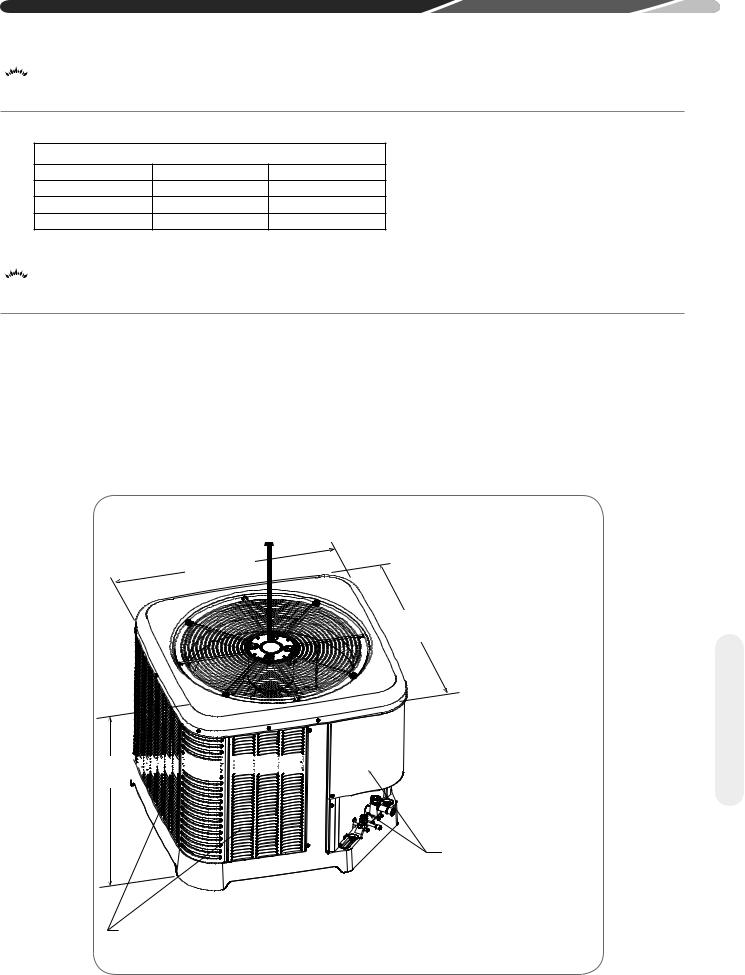
ALLOW 60" [152.4 cm] OF CLEARANCE
“W”
“L”
“H” 


SERVICE2 PANELS/ INLET CONNECTIONS / HIGH & LOW VOLTAGE ACCESS ALLOW
24" [61.0 cm] OF CLEARANCE
AIR INLET LOUVERS ALLOW
6" [15.2 cm] OF CLEARANCE ALL SIDES ST-A1226-02-00 12" [30.5 cm] RECOMMENDED
<![endif]>Specifications Unit
7

<![endif]>Tools
4.0 INSTALLATION
 4.1 Tools and Refrigerant
4.1.1 Tools Required for Installing
and Servicing R-410A Models
Manifold Sets:
–Up to 800 PSIG [5,516 kPa] High-Side
–Up to 250 PSIG [1,724 kPa] Low-Side
–550 PSIG [3,792 kPa] Low-Side Retard Manifold Hoses:
–Service Pressure Rating of 800 PSIG [5,516 kPa] Recovery Cylinders:
–400 PSIG [2,758 kPa] Pressure Rating
–Dept. of Transportation 4BA400 or BW400
1 |
2 |
4
3
7
5
6
8 9
 CAUTION: R-410A systems operate at higher pressures than R-22 systems. Do not use R-22 service equipment or components on R-410A equipment.
4.1.2 Specifications of R-410A
Application: R-410A is not a drop-in replacement for R-22. Equipment designs must accommodate its higher pressures. It cannot be retrofitted into R-22 heat pumps.
Physical Properties: R-410A has an atmospheric boiling point of -62.9°F [-52.7°C] and its saturation pressure at 77°F [25°C] is 224.5 psig [1,548 kPa].
Composition: R-410A is a near-azeotropic mixture of 50% by weight difluoromethane (HFC32) and 50% by weight pentafluoroethane (HFC125).
Pressure: The pressure of R-410A is
approximately 60% (1.6 times) greater than R-22. Recovery and recycle equipment, pumps, hoses, and the like must have design pressure ratings appropriate for R-410A. Manifold sets need
to range up to 800 psig [5,516 kPa] high-side and 250 psig [1,724 kPa] low-side with a 550 psig [3,792 kPa] low-side retard. Hoses need to have a service pressure rating of 800 psig [5,516 kPa].
Recovery cylinders need to have a 400 psig [2,758 kPa] service pressure rating, DOT 4BA400 or DOT BW400.
Combustibility: At pressures above 1 atmosphere, a mixture of R-410A and air can become combustible. R-410A and air should
never be mixed in tanks or supply lines or be allowed to accumulate in storage tanks.
Leak checking should never be done with a mixture of R-410A and air. Leak-checking can be performed safely with nitrogen or a mixture of R-410A and nitrogen.
4.1.3 Quick-Reference Guide for R-410A
•R-410A refrigerant operates at approximately 60% higher pressure (1.6 times) than R-22. Ensure that servicing equipment is designed to operate with R-410A.
•R-410A refrigerant cylinders are light rose in color.
•R-410A, as with other HFCs, is only compatible with POE oils.
•Vacuum pumps will not remove moisture from POE oil used in R-410A systems.
•R-410A systems are to be charged with liquid refrigerants. Prior to March 1999, R-410A refrigerant cylinders had a dip tube. These cylinders should be kept upright for equipment charging. Post-March 1999 cylinders do not have a dip tube and should be inverted to ensure liquid charging of the equipment.
•Do not install a suction line filter drier in the liquid line.
•A factory-approved bi-flow liquid line filter drier
is shipped with every unit and must be installed in the liquid line at the time of installation. Only manufacturer-approved liquid line filter driers should be used. Filter driers must have a working pressure rating of at least 600 psig [4,137 kPa]. The filter drier will only have adequate moistureholding capacity if the system is properly evacuated.
•Desiccant (drying agent) must be compatible for POE oils and R-410A refrigerant.
8
4.0 INSTALLATION
 4.2 Choosing a Location
4.2.1 Allowable Clearances
12" [30.5 cm] to side intake louvers 24" [61.0 cm] to service access panels
60" [152.4 cm] vertical for fan discharge
If space limitations exist, the following clearances will have minimal impact to capacity and efficiency and are permitted:
Single-Unit Applications: Minimum of 6" [15.2 cm] to side intake louvers. DO NOT reduce the 60" [152.4 cm] for fan discharge or the 24" [61.0 cm] service clearances.
Multiple-Unit Applications: For units positioned next to each other, a minimum of 6" [15.2 cm] clearance between units is recommended for 2 ton models and 9" [22.9 cm] for 3 ton to 5 ton models. Do not reduce the 60" [152.4 cm] for fan discharge or the 24" [61.0 cm] service clearances.
IMPORTANT: Consult local and national building codes and ordinances for special installation requirements. Following location information will provide longer life and simplified servicing of the outdoor heat pump.
NOTICE: These units must be installed outdoors. No ductwork can be attached, or other modifications made, to the discharge grille.
Modifications will affect performance or operation.
3
4
2
1 |
ST-A1226-04-00 |
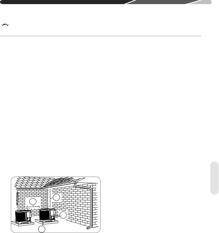
4.2.2 Operational Issues Related to Unit Location
IMPORTANT: Locate the unit in a manner that will not prevent, impair, or compromise the performance of other equipment installed
in proximity to the unit. Maintain all required minimum distances to gas and electric meters, dryer vents, and exhaust and inlet openings. In the absence of national codes or manufacturers’ recommendations, local code recommendations and requirements will take precedence.
•Refrigerant piping and wiring should be properly sized and kept as short as possible to avoid capacity losses and increased operating costs.
•Locate the unit where water runoff will not create a problem with the equipment. Position the unit away from the drip edge of the roof whenever possible. Units are weatherized, but can be affected by the following:
•Water pouring into the unit from the junction of rooflines, without protective guttering. Large volumes of water entering the heat pump while in operation can impact fan blade or motor life, and coil damage may occur to a heat pump if
moisture cannot drain from the unit under freezing conditions.
•Freezing moisture or sleeting conditions can cause the cabinet to ice-over prematurely and prevent heat pump operation, requiring backup heat, which generally results in less economical operation It is highly recommended to switch the EcoNet™ Control Center or thermostat to the "Emergency Heat" mode during freezing rain
or sleeting conditions to prevent damage to the outdoor coil from ice accumulating on the fan blade.
•Closely follow the clearance recommendations in section 4.2.1.
•24" [61.0 cm] to the service panel access.
•60" [152.4 cm] above the fan discharge (unit top) to prevent recirculation.
•6" [15.2 cm] to the coil grille air inlets
with 12" [30.5 cm] minimum recommended.
<![endif]>Location
9
<![endif]>Location
4.0 INSTALLATION
 4.2 Choosing a Location (cont.)
4.2.3 Corrosive Environment
The metal parts of this unit may be subject to rust or deterioration if exposed to a corrosive environment. This oxidation could shorten the equipment’s useful life.
Corrosive elements include, but are not limited to, salt spray, fog or mist in seacoast areas, sulphur or chlorine from lawn watering systems, and various chemical contaminants from industries such as paper mills and petroleum refineries.
If the unit is to be installed in an area where contaminants are likely to be a problem, special attention should be given to the equipment location and exposure.
•Avoid having lawn sprinkler heads spray directly on the unit cabinet.
•In coastal areas, locate the unit on the side of the building away from the waterfront.
•Shielding provided by a fence or shrubs may give some protection, but cannot violate minimum airflow and service access clearances.
4.3 Unit Mounting
4.3.1 Unit Mounting Methods
The outdoor heat pump unit may be mounted in a number of ways. The most common method is on the ground mounted on a concrete or pre-fabricated pad. It can also be mounted on a ground or roof mounted metal frame, wooden frame, or 4” x 4” [10.2 cm x 10.2 cm] wooden stringers. It is extremely important to properly secure the unit to the pad or frame so it does not shift during high winds, seismic events, or other outside forces to eliminate the possibility of a safety hazard or physical damage to the unit. Local codes in regions subject to frequent hurricanes and seismic events will dictate specific mounting requirements and must be followed. It is also important to elevate the heat pump in areas that receive a significant amount of snowfall so accumulated snow does not block the outdoor
coil and interfere with drainage of water during the defrost cycle. Refer to Section 4.3.4 for typical
ground snow levels for different regions of the USA.
 WARNING: Disconnect all power to unit before starting maintenance. Failure to do so can cause electrical shock resulting in severe personal injury or death.
Regular maintenance will reduce the buildup of contaminants and help to protect the unit’s finish.
•Frequent washing of the cabinet, fan blade, and coil with fresh water will remove most of the salt or other contaminants that build up on the unit.
•Regular cleaning and waxing of the cabinet with a good automobile polish will provide some protection.
•A good liquid cleaner may be used several times a year to remove matter that will not wash off with water.
4.2.4 Customer Satisfaction Issues
•The heat pump should be located away from the living, sleeping, and recreational spaces of the owner and those spaces on adjoining property.
•To prevent noise transmission, the mounting pad for the outdoor unit should not be connected to the structure and should be located a sufficient
distance above grade to prevent ground water from entering the unit.
4.3.2 High Wind and Seismic Tie-
Down Methods
The manufacturer-approved/recommended method is a guide to securing equipment for wind and seismic loads. Other methods might provide the same result, but the manufacturer method is the only one endorsed by the manufacturer for securing equipment where wind or earthquake damage
can occur. Additional information is available on the manufacturer's website or from the wholesale distributor.
10
4.0 INSTALLATION
4.3.3 Elevating Unit
 WARNING: Secure an elevated unit and its elevating stand in order to prevent tipping. Failure to do so may result in severe personal injury or death.
If elevating the heat pump, either on a flat roof or on a slab, observe the following guidelines.
•If elevating a unit on a flat roof, use 4" x 4"
[10.2 cm x 10.2 cm] or equivalent stringers positioned to distribute unit weight evenly and prevent noise and vibration.
•Heat pump products will need to be elevated per local climate and code requirements to provide clearance above the estimated snowfall level to ensure the unit will be protected from damage. Failure to follow these instructions may result in equipment damage and improper operation.
NOTICE: Do not block drain openings on bottom of unit.
•If unit must be elevated because of anticipated snowfall, secure unit and elevating stand such that unit and/or stand will not tip over or fall off. Keep in mind that someone may try to climb on unit.
1
2
<![if ! IE]><![endif]>Location
3
ST-A1226-03-00
11

<![endif]>Tubing
4.0 INSTALLATION
 4.4 Refrigerant Line Set Selection
4.4.1 Replacing Existing
Systems
To prevent failure of a new unit, the existing line set must be correctly sized for the new unit and must be cleaned or replaced. Care must be taken so
the expansion device is not plugged. For new and replacement units, a liquid line filter drier must be installed and the line set must be properly sized. Test the oil for acid. If it tests positive for acid, a suction line filter drier is mandatory.
IMPORTANT: When replacing an R-22 unit with an R-410A unit, either replace the line set or ensure that residual mineral oil is
drained from existing lines including oil trapped in low spots.
4.4.2 Line Set Application
Considerations
The following are special considerations that need to be addressed when selecting and installing a line set.
•Additional refrigerant charge
•Fitting losses and maximum equivalent length considerations
•Refrigerant migration during the off cycle
•Oil return to the compressor
•Capacity losses
•System oil level adjustment
4.4.2.1 Oil Return to Compressor
Small amounts of compressor crankcase oil is picked up and carried out of the compressor by the moving refrigerant and is circulated through the system along with the refrigerant before it returns to the compressor crankcase. It is critical to the life of the compressor for the oil to be able to return to the compressor to maintain an adequate level of oil in the compressor crankcase. Oversized vapor lines result in inadequate refrigerant velocities to carry the oil along with the refrigerant and will cause the oil to accumulate in the low spots in the vapor line instead of being returned to the compressor crankcase. This is especially true for long line lengths. Variable speed systems present an additional challenge due to the fact that the system operates at
a significantly reduced refrigerant flow rate for a significant percentage of operating time. Only use the vapor line sizes listed in Table 2 to assure proper oil return. DO NOT oversize vapor line!
4.4.2.2 Refrigerant Migration During Off
Cycle
Long line set applications can require a considerable amount of additional refrigerant. This additional refrigerant needs to be managed throughout the entire ambient operating envelope that the system will go through during its life cycle. Off-Cycle migration is where excess refrigerant condenses and migrates to the coldest and/or lowest part of the system. Excessive build-up of refrigerant at the compressor will result in poor reliability and noisy operation during startup. Section 4.5.2 demonstrates the required unit configuration for different applications.
4.4.2.3 Maximum Liquid Pressure Drop
The total liquid line pressure drop must not exceed 50 psig [345 kPa] to assure a solid column of liquid at the metering device and stable control of superheat. Be sure to account for vertical separation, elbows, filter driers, solenoid valves, sight glasses, and check valves when calculating liquid line pressure drop.
4.4.2.4 Liquid Line Refrigerant Flashing
Excessive pressure drop and heat gain in long liquid lines can result in the refrigerant flashing into a vapor before it reaches the expansion device which will dramatically reduce the capacity and efficiency of the system. For this reason, the liquid line must be sized properly using Table 2 and must be insulated in unconditioned spaces.
12

4.4.2.5 Oil Level Adjustment for Long Line Set Applications
Additional oil may need to be added if refrigerant is added during installation. If the system contains more than 20 lbs [9 kg] of refrigerant charge, add 1 fluid oz of
POE oil for every 5 lbs [13 ml/kg] of refrigerant charge over 20 lbs [9 kg].
4.0 INSTALLATION
4.4.2.6 Capacity Losses
Long line lengths can result in a reduction in capacity due to vapor line pressure drop and heat gain or loss. Refer to Table 2 for capacity loss multipliers for various vapor line diameters and equipment line lengths. This table does not account for any capacity loss due to heat gain or loss from the environment. It is extremely important not to oversize the vapor line to minimize capacity loss at the expense of proper oil return. If the table shows an “NR” for a particular vapor line diameter and length, or, if a vapor line diameter is not listed, oil return will not be adequate.
4.4.3 Line Set Length and Fitting Losses
Refrigerant tubing is measured in terms of actual length and equivalent length. Actual length is used for refrigerant charge applications. Equivalent length takes into account pressure losses from tubing length, fittings,
vertical separation, accessories, and filter driers. The table below references different commonly used equivalent lengths.
Table 1
Line Size |
90° Short |
90° Long |
45° |
Solenoid |
Check |
Sight |
Filter |
|
Radius |
Radius |
|||||||
in [mm] |
Elbow |
Valve |
Valve |
Glass |
Drier |
|||
Elbow |
Elbow |
|||||||
|
|
|
|
|
|
|||
|
|
|
|
|
|
|
|
|
3/8 [9.53] |
1.3 [0.40] |
0.8 [0.24] |
0.3 [0.09] |
6 [1.83] |
4 [1.22] |
0.4 [0.12] |
6 [1.83] |
|
|
|
|
|
|
|
|
|
|
1/2 [12.71] |
1.4 [0.43] |
0.9 [0.27] |
0.4 [0.12] |
9 [2.74] |
5 [1.52] |
0.6 [0.18] |
6 [1.83] |
|
|
|
|
|
|
|
|
|
|
5/8 [15.88] |
1.5 [0.46] |
1 [0.30] |
0.5 [0.15] |
12 [3.66] |
6 [1.83] |
0.8 [0.24] |
6 [1.83] |
|
|
|
|
|
|
|
|
|
|
3/4 [19.05] |
1.9 [0.58] |
1.3 [0.40] |
0.6 [0.18] |
14 [4.27] |
7 [2.13] |
0.9 [0.27] |
6 [1.83] |
|
|
|
|
|
|
|
|
|
|
7/8 [22.23] |
2.3 [0.70] |
1.5 [0.46] |
0.7 [0.21] |
15 [4.57] |
8 [2.44] |
1 [0.30] |
6 [1.83] |
|
|
|
|
|
|
|
|
|
|
1-1/8 [28.58] |
2.7 [0.82] |
1.8 [0.55] |
0.9 [0.27] |
22 [6.71] |
12 [3.66] |
1.5 [0.46] |
6 [1.83] |
<![endif]>Tubing
13
4.0 INSTALLATION
4.4.4 Liquid Line Selection
The purpose of the liquid line is to transport warm sub-cooled liquid refrigerant between the outdoor unit to the indoor unit in the cooling mode. In the heating mode, the liquid line returns sub-cooled liquid from the indoor unit to the outdoor unit. It is important not to allow the refrigerant to flash into superheated vapor prior to entering the expansion device of the indoor coil or outdoor unit. Flashing of refrigerant can occur for the following reasons:
•Low refrigerant charge
•Improperly selected liquid line size
•Absorption of heat prior to expansion device
•Excessive vertical separation between the outdoor unit and indoor coil
•Restricted liquid linear filter drier
•Kinked liquid line
The total pressure drop allowed for the liquid line is 50 PSI [345 kPa]. The procedure for selecting the proper liquid line is as follows:
• Measure the total amount of vertical separation between the outdoor unit and indoor coil.
Example Table (Excerpt from Table 2A)
•Measure the total indoor length of liquid line required.
•Add all of the equivalent lengths associated with any fittings or accessories using Table 1.
•Add the linear length to the total fitting equivalent length. This will equal your total equivalent line length.
•Reference Table 2 to verify the calculated equivalent length is acceptable with the required vertical separation and diameter of liquid line.
Example: A 3-ton heat pump unit is installed 25’ below the indoor unit, requires a 75’ of 1/2” diameter liquid line, 3/4" vapor line, 4 90° LR elbows and a filter drier.
• Fitting Equivalent Length (ft.) = 4 × .9' + 6' = 9.6’
• Total Equivalent Length (ft.) = 75’ + 9.6' = 84.6’ This application is acceptable because the 25’ vertical rise is less than the maximum rise of 50’ for this application.
|
|
Allowable |
|
Outdoor Unit ABOVE or BELOW Indoor Unit |
|
||||
|
Allowable |
|
|
Equivalent Length (Feet) |
|
|
|||
|
Vapour |
|
|
|
|
|
|
||
Unit Size |
Liquid Line |
< 25 |
26-50 |
51-75 |
76-100 |
101-125 |
126-150 |
||
Line |
|||||||||
|
Size |
||||||||
|
Size |
|
|
|
|
|
|
||
|
|
Maximum Vertical Separation / Capacity Multiplier |
|
||||||
|
|
|
|
||||||
|
|
|
|
|
|||||
|
|
|
|
|
|
|
|
|
|
|
5/16" |
5/8" |
25 / 0.99 |
50 / 0.97 |
50 / 0.95 |
50 / 0.93 |
36 / 0.91 |
NR |
|
|
|
|
|
|
|
|
|
|
|
|
3/8" |
5/8" |
25 / 0.99 |
50 / 0.97 |
50 / 0.95 |
50 / 0.93 |
50 / 0.91 |
NR |
|
|
|
|
|
|
|
|
|
|
|
3 Ton |
5/16" |
3/4" |
25 / 1.00 |
50 / 0.99 |
50 / 0.99 |
50 / 0.98 |
36 / 0.97 |
20 / 0.96 |
|
|
|
|
|
|
|
|
|
|
|
|
3/8" |
3/4" |
25 / 1.00 |
50 / 0.99 |
50 / 0.99 |
50 / 0.98 |
50 / 0.97 |
50 / 0.96 |
|
|
|
|
|
|
|
|
|
|
|
|
1/2" |
3/4" |
25 / 1.00 |
50 / 0.99 |
50 / 0.99 |
50 / 0.98 |
50 / 0.97 |
50 / 0.96 |
|
|
|
|
|
|
|
|
|
|
|
<![endif]>Tubing
4.4.5 Vapor Line Selection
The purpose of the vapor line is to return superheated vapor to the condensing unit from the indoor coil in the cooling mode. While in the heating mode, the vapor line transports discharge vapor to the indoor coil from the outdoor unit. Proper vapor line sizing is important because it plays an important role in returning oil to the compressor to prevent potential damage to the bearings, valves, and scroll sets. Also, an improperly sized vapor line can dramatically reduce capacity and performance of the system. The procedure for selecting the proper vapor line is as follows:
•Determine the total linear length of vapor line required.
•Add all of the equivalent lengths associated with any fittings or accessories using Table 1.
•Add the linear length and total fitting equivalent length. This will equal your total equivalent line length.
•Reference Table 2 to verify that the calculated equivalent length falls within the compatibility region of the chart.
•Verify capacity loss is acceptable for the application.
14
4.0 INSTALLATION
Table 2A: Refrigerant Line Sizing Chart (English Units)
15/16 SEER2 Variable Speed Heat Pumps/Air Conditioner
|
|
Allowable |
|
Outdoor Unit ABOVE or BELOW Indoor Unit |
|
|
|||||
|
Allowable |
|
|
Equivalent Length (Feet) |
|
|
|
||||
|
Vapour |
|
|
|
|
|
|||||
Unit Size |
Liquid Line |
|
|
|
|
|
|
|
|
||
Line |
< 25 |
26-50 |
51-75 |
|
76-100 |
101-125 |
126-150 |
|
|||
|
Size |
|
|
||||||||
|
Size |
|
|
|
|
|
|
|
|
||
|
|
|
Maximum Vertical Separation / Capacity Multiplier |
|
|
||||||
|
|
|
|
|
|
||||||
|
1/4" |
5/8" |
25 /1.00 |
50 / 0.99 |
33 / 0.98 |
|
6 / 0.97 |
NR |
NR |
|
|
|
5/16" |
5/8" |
25 /1.00 |
50 / 0.99 |
33 / 0.98 |
|
50 / 0.97 |
50 / 0.96 |
50 / 0.95 |
|
|
2.0 Ton |
3/8" |
5/8" |
25 /1.00 |
50 / 0.99 |
33 / 0.98 |
|
50 / 0.97 |
50 / 0.96 |
50 / 0.95 |
|
|
*SEE |
|
|
|
|
|
|
|
|
|
|
|
1/4" |
3/4" * |
25 /1.00 |
50 / 1.00 |
33 / 0.99 |
|
6 / 0.99 |
NR |
NR |
|
||
NOTE 3 |
|
|
|||||||||
|
5/16" |
3/4" * |
25 /1.00 |
50 / 1.00 |
50 / 0.99 |
|
50 / 0.99 |
50 / 0.99 |
50 / 0.98 |
|
|
|
|
|
|
|
|
|
|
|
|
|
|
|
3/8" |
3/4" * |
25 /1.00 |
50 / 1.00 |
50 / 0.99 |
|
50 / 0.99 |
50 / 0.99 |
50 / 0.98 |
|
|
|
5/16" |
5/8" |
25 / 0.99 |
50 / 0.97 |
50 / 0.95 |
|
50 / 0.93 |
36 / 0.91 |
NR |
|
|
|
3/8" |
5/8" |
25 / 0.99 |
50 / 0.97 |
50 / 0.95 |
|
50 / 0.93 |
50 / 0.91 |
NR |
|
|
3 Ton |
5/16" |
3/4" |
25 / 1.00 |
50 / 0.99 |
50 / 0.99 |
|
50 / 0.98 |
36 / 0.97 |
20 / 0.96 |
|
|
|
3/8" |
3/4" |
25 / 1.00 |
50 / 0.99 |
50 / 0.99 |
|
50 / 0.98 |
50 / 0.97 |
50 / 0.96 |
|
|
|
1/2" |
3/4" |
25 / 1.00 |
50 / 0.99 |
50 / 0.99 |
|
50 / 0.98 |
50 / 0.97 |
50 / 0.96 |
|
|
|
3/8" |
3/4" |
25 / 0.99 |
50 / 0.98 |
50 / 0.96 |
|
50 / 0.95 |
50 / 0.93 |
50 / 0.92 |
|
|
4 Ton |
1/2" |
3/4" |
25 / 0.99 |
50 / 0.98 |
50 / 0.96 |
|
50 / 0.95 |
50 / 0.93 |
50 / 0.92 |
|
|
3/8" |
7/8" |
25 / 1.00 |
50 / 0.99 |
50 / 0.99 |
|
50 / 0.98 |
50 / 0.98 |
50 / 0.97 |
|
||
|
|
|
|||||||||
|
1/2" |
7/8" |
25 / 1.00 |
50 / 0.99 |
50 / 0.99 |
|
50 / 0.98 |
50 / 0.98 |
50 / 0.97 |
|
|
|
3/8" |
3/4" |
25 / 0.98 |
50 / 0.97 |
50 / 0.95 |
|
50 / 0.93 |
46 / 0.91 |
NR |
|
|
5 Ton |
1/2" |
3/4" |
25 / 0.98 |
50 / 0.97 |
50 / 0.95 |
|
50 / 0.93 |
50 / 0.91 |
NR |
|
|
3/8" |
7/8" |
25 / 0.99 |
50 / 0.99 |
50 / 0.98 |
|
50 / 0.97 |
50 / 0.96 |
38 / 0.95 |
|
||
**SEE |
|
|
|
|
|
|
|
|
|
|
|
1/2" |
7/8" |
25 / 0.99 |
50 / 0.99 |
50 / 0.98 |
|
50 / 0.97 |
50 / 0.96 |
50 / 0.95 |
|
||
NOTE 4 |
|
|
|||||||||
|
3/8" |
1-1/8" ** |
25 / 1.00 |
50 / 1.00 |
50 / 1.00 |
|
50 / 0.99 |
50 / 0.99 |
38 / 0.99 |
|
|
|
1/2" |
1-1/8" ** |
25 / 1.00 |
50 / 1.00 |
50 / 1.00 |
|
50 / 0.99 |
50 / 0.99 |
50 / 0.99 |
|
|
Notes: |
|
|
|
|
|
|
|
|
|
|
|
1) Do not exceed 150 ft linear line length. |
|
|
|
|
|
|
|
||||
2) Do not exceed 50 ft vertical separation between indoor and outdoor units. |
|
|
|
|
|||||||
3) * 3/4" vapour line should only be used for 2 ton systems if outdoor unit is below or at same level as indoor |
|
||||||||||
unit to assure proper oil return. |
|
|
|
|
|
|
|
|
|||
4) ** 1-1/8" vapour line should only be used for 5 ton systems if outdoor unit is below or at same level as indoor |
|
||||||||||
unit to assure proper oil return. |
|
|
|
|
|
|
|
|
|||
5) Always use the smallest liquid line allowable to minimize refrigerant charge. |
|
|
|
|
|||||||
6) Applications shaded in light Gray indicate capacity multipliers between 0.90 and 0.96 which are not |
|
<![if ! IE]> <![endif]>Tubing |
|||||||||
recommended, but are allowed. |
|
|
|
|
|
|
|
||||
7) Applications shaded in dark Gray are not recommended due to excessive liquid or suction pressure drop. |
|||||||||||
|
|||||||||||
15
4.0 INSTALLATION
Table 2B: Refrigerant Line Sizing Chart (Metric Units)
15/16 SEER2 Variable Speed Heat Pumps/Air Conditioner
|
Allowable |
Allowable |
|
|
Outdoor Unit ABOVE or BELOW Indoor Unit |
|
|||||||
|
|
|
|
Equivalent Length (Feet) |
|
|
|
||||||
Unit Size |
Liquid Line |
Vapour Line |
|
|
|
|
|
|
|||||
Size |
Size |
< 8 |
|
8-15 |
|
16-23 |
24-30 |
|
31-38 |
|
39-46 |
||
|
|
|
|
|
|||||||||
|
mm [in.] |
mm [in.] |
|
|
|
|
|
|
|
|
|
|
|
|
|
Maximum Vertical Separation / Capacity Multiplier |
|
||||||||||
|
|
|
|
|
|
||||||||
|
6.35 [1/4] |
15.88 [5/8] |
8 / 1.00 |
|
15 / 0.99 |
|
10 / 0.98 |
2 / 0.97 |
|
NR |
|
NR |
|
7.0 KW |
7.94 [5/16] |
15.88 [5/8] |
8 / 1.00 |
|
15 / 0.99 |
|
15 / 0.98 |
15 / 0.97 |
|
15 / 0.96 |
|
15 / 0.95 |
|
9.53 |
[3/8] |
15.88 [5/8] |
8 / 1.00 |
|
15 / 0.99 |
|
15 / 0.98 |
15 / 0.97 |
|
15 / 0.96 |
|
15 / 0.95 |
|
[2.0 Ton] |
|
|
|
|
|||||||||
*SEE |
6.35 [1/4] |
19.05 [3/4] * |
8 / 1.00 |
|
15 / 0.99 |
|
10 / 0.99 |
2 / 0.99 |
|
NR |
|
NR |
|
NOTE 3 |
|
|
|
|
|
|
|
|
|
|
|
|
|
7.94 [5/16] |
19.05 [3/4] * |
8 / 1.00 |
|
15 / 0.99 |
|
15 / 0.99 |
15 / 0.99 |
|
15 / 0.99 |
|
15 / 0.98 |
||
|
|
|
|
|
|||||||||
|
|
|
|
|
|
|
|
|
|
|
|
|
|
|
9.53 |
[3/8] |
19.05 [3/4] * |
8 / 1.00 |
|
15 / 0.99 |
|
15 / 0.99 |
15 / 0.99 |
|
15 / 0.99 |
|
15 / 0.98 |
|
7.94 [5/16] |
15.88 [5/8] |
8 / 0.99 |
|
15 / 0.97 |
|
15 / 0.95 |
15 / 0.93 |
|
11 / 0.91 |
|
NR |
|
10.6 KW |
9.53 |
[3/8] |
15.88 [5/8] |
8 / 0.99 |
|
15 / 0.97 |
|
15 / 0.95 |
15 / 0.93 |
|
15 / 0.91 |
|
NR |
7.94 [5/16] |
19.05 [3/4] |
8 / 1.00 |
|
15 / 0.99 |
|
15 / 0.99 |
15 / 0.98 |
|
11 / 0.97 |
|
6 / 0.96 |
||
[3 Ton] |
|
|
|
|
|||||||||
9.53 |
[3/8] |
19.05 [3/4] |
8 / 1.00 |
|
15 / 0.99 |
|
15 / 0.99 |
15 / 0.98 |
|
15 / 0.97 |
|
15 / 0.96 |
|
|
|
|
|
|
|||||||||
|
12.7 |
[1/2] |
19.05 [3/4] |
8 / 1.00 |
|
15 / 0.99 |
|
15 / 0.99 |
15 / 0.98 |
|
15 / 0.97 |
|
15 / 0.96 |
|
9.53 |
[3/8] |
19.05 [3/4] |
8 / 0.99 |
|
15 / 0.98 |
|
15 / 0.96 |
15 / 0.95 |
|
15 / 0.93 |
|
15 / 0.92 |
14.1 KW |
12.7 |
[1/2] |
19.05 [3/4] |
8 / 0.99 |
|
15 / 0.98 |
|
15 / 0.96 |
15 / 0.95 |
|
15 / 0.93 |
|
15 / 0.92 |
[4 Ton] |
9.53 |
[3/8] |
22.23 [7/8] |
8 / 1.00 |
|
15 / 0.99 |
|
15 / 0.99 |
15 / 0.98 |
|
15 / 0.98 |
|
15 / 0.97 |
|
12.7 |
[1/2] |
22.23 [7/8] |
8 / 1.00 |
|
15 / 0.99 |
|
15 / 0.99 |
15 / 0.98 |
|
15 / 0.98 |
|
15 / 0.97 |
|
9.53 |
[3/8] |
19.05 [3/4] |
8 / 0.98 |
|
15 / 0.97 |
|
15 / 0.95 |
15 / 0.93 |
|
14 / 0.91 |
|
NR |
17.6 KW |
12.7 |
[1/2] |
19.05 [3/4] |
8 / 0.98 |
|
15 / 0.97 |
|
15 / 0.95 |
15 / 0.93 |
|
15 / 0.91 |
|
NR |
9.53 |
[3/8] |
22.23 [7/8] |
8 / 0.99 |
|
15 / 0.99 |
|
15 / 0.98 |
15 / 0.97 |
|
15 / 0.96 |
|
12 / 0.95 |
|
[5 Ton] |
|
|
|
|
|||||||||
**SEE |
12.7 |
[1/2] |
22.23 [7/8] |
8 / 0.99 |
|
15 / 0.99 |
|
15 / 0.98 |
15 / 0.97 |
|
15 /0.96 |
|
15 / 0.95 |
NOTE 4 |
|
|
|
|
|
|
|
|
|
|
|
|
|
9.53 |
[3/8] |
28.58 [1-1/8] ** |
8 / 1.00 |
|
15 / 1.00 |
|
15 / 1.00 |
15 / 0.99 |
|
15 / 0.99 |
|
12 / 0.99 |
|
|
|
|
|
|
|||||||||
|
12.7 |
[1/2] |
28.58 [1-1/8] ** |
8 / 1.00 |
|
15 / 1.00 |
|
15 / 1.00 |
15 / 0.99 |
|
15 / 0.99 |
|
15 / 0.99 |
Notes:
1)Do not exceed 46 meters linear line length.
2)Do not exceed 15 meters vertical separation between indoor and outdoor units.
3)*19.05mm [3/4 in.] vapour line should only be used for 2 ton systems if outdoor unit is below or at same level as indoor unit to assure proper oil return.
4)**28.58mm [1-1/8 in.] vapour line should only be used for 5 ton systems if outdoor unit is below or at same level as indoor unit to assure proper oil return.
5)Always use the smallest liquid line allowable to minimize refrigerant charge.
6)Applications shaded in light Gray indicate capacity multipliers between 0.90 and 0.96 which are not recommended, but are allowed.
7)Applications shaded in dark Gray are not recommended due to excessive liquid or suction pressure drop.
<![endif]>Tubing
Additional Oil, Oz. 16 SEER2 Heat Pump
Lineset |
50 |
60 |
70 |
80 |
90 |
100 |
110 |
120 |
130 |
140 |
150 |
|
Length, Ft |
||||||||||||
|
|
|
|
|
|
|
|
|
|
|
||
2T |
N/A |
1 |
3 |
4 |
5 |
7 |
8 |
9 |
11 |
12 |
13 |
|
3T |
N/A |
N/A |
N/A |
N/A |
1 |
2 |
3 |
5 |
6 |
7 |
9 |
|
4T |
N/A |
N/A |
N/A |
N/A |
N/A |
N/A |
N/A |
N/A |
N/A |
0 |
1 |
|
5T |
2 |
3 |
4 |
6 |
7 |
8 |
10 |
11 |
12 |
14 |
15 |
16
4.0 INSTALLATION
Additional Oil, Oz. 15/16 SEER2 Air Conditoner
Lineset |
50 |
60 |
70 |
80 |
90 |
100 |
110 |
120 |
130 |
140 |
150 |
|
Length, Ft |
||||||||||||
|
|
|
|
|
|
|
|
|
|
|
||
2T |
N/A |
N/A |
N/A |
N/A |
N/A |
1 |
2 |
3 |
5 |
6 |
7 |
|
3T |
N/A |
N/A |
N/A |
N/A |
N/A |
N/A |
1 |
2 |
3 |
5 |
6 |
|
4T |
N/A |
N/A |
N/A |
N/A |
N/A |
N/A |
N/A |
N/A |
N/A |
N/A |
N/A |
|
5T |
N/A |
N/A |
N/A |
N/A |
N/A |
N/A |
N/A |
N/A |
N/A |
N/A |
N/A |
4.5 Line Set Installation
•If tubing is to be run underground, it must be run in a sealed watertight chase.
•Use care in routing tubing and do not kink or twist. Use a good quality tubing bender on the vapor line to prevent kinking.
in the heating mode will result in noise inside the structure.
•Blow out the liquid and vapor lines with dry nitrogen before connecting to the outdoor unit and indoor coil to remove debris that can plug the expansion device.
1 |
2 |
|
•Route the tubing using temporary hangers; then straighten the tubing and install permanent hangers. The tubing must be adequately supported.
•Isolate the vapor line from the building structure. If the vapor line comes in contact with inside walls, ceiling, or flooring, the vibration of the vapor line
ST-A1226-05-00
4.5.1 Important Tubing Installation Practices
Observe the following when installing correctly sized type “L” refrigerant tubing between the outdoor unit and indoor coil:
•Check Table 2 for the correct vapor line size and liquid line size.
•If a portion of the liquid line passes through a very hot area where liquid refrigerant can be heated to form vapor, insulating the liquid line is required.
•Use clean, dehydrated, sealed refrigeration-grade tubing.
•Always keep tubing sealed until tubing is in place and connections are to be made.
•A high-quality biflow filter drier is included with all R-410A heat pump units and must be installed in the liquid line upon unit installation.
•When replacing an R-22 system with an R-410A system and the line set is not replaced, blow out the lines with dry nitrogen to remove as much of the
remaining mineral oil as possible. Check for low spots where oil may be trapped and take measures to drain the oil from those areas.
•If tubing has been cut, debur the ends while holding the tubing in a position to prevent chips from
falling into tubing. Burrs such as those caused by tubing cutters can affect performance dramatically, particularly on small diameter liquid lines.
•For best operation, keep tubing run as short as possible with a minimum number of elbows or bends.
•Locations where the tubing will be exposed to mechanical damage should be avoided. If it is necessary to use such locations, the copper tubing should be protected by a housing to prevent damage.
<![endif]>Tubing
17
4.0 INSTALLATION
 4.5 Line Set Installation (cont.)
4.5.2 Relative Location of Indoor and Outdoor Units
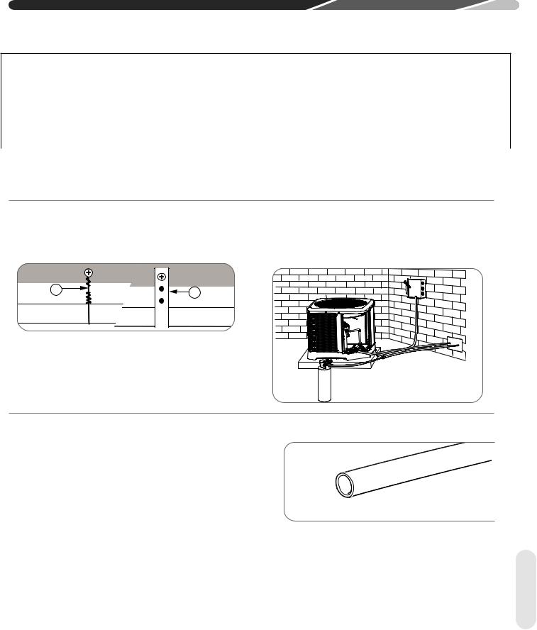
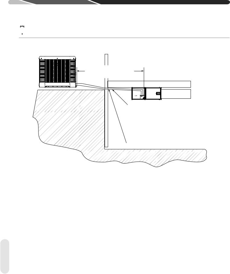
4.5.2.1 Outdoor Unit Level or Near Level to Indoor Coil Line Set
REFERENCE TABLE 2 FOR
MAXIMUM LENGTH LIMITATIONS
IDEALLY, LINE SET SLOPES AWAY
FROM OUTDOOR UNIT. VERIFY
SUB-COOLING PRIOR TO EXPANSION
DEVICE, INSULATED LIQUID LINE IN
UNCONDITIONED SPACE FOR
LONG LINE APPLICATIONS.
INSULATED VAPOR LINE FULL LENGTH
ST-A1219-01-01
Figure 3
For applications with the outdoor unit and indoor unit on the same level the following is required:
•Insulated liquid line in unconditioned space only.
•Insulated vapor line full length.
•Vapor line should slope toward the indoor unit. (Reference Figure 3)
•Follow the proper line sizing, maximum linear and equivalent length, charging requirements, and oil level adjustments spelled out in this document.
•Verify at least 5°F [2.8°C] sub-cooling at the indoor unit prior to expansion device.
<![endif]>Tubing
18
 Loading...