


U35 Gas Insert
MODELS: U35-NG Natural Gas U35-LP Propane
Owners & Installation Manual
WARNING:
Improper installation, adjustment, alteration, service or maintenance can cause injury, property damage, or loss of life. Refer to this manual. For assistance or additional information consult an authorized installer, service agency or the gas supplier.
FOR YOUR SAFETY
Do not store or use gasoline or other flammable vapours and liquids in the vicinity of this or any other appliance.
Installation and service must be performed by an authorized installer, service agency or the gas supplier.
FOR YOUR SAFETY
What to do if you smell gas:
 Do not try to light any appliance
 Do not touch any electrical switch: do not use any phone in your building.
 Immediately call your gas supplier from a neighbour's phone. Follow the gas supplier's instructions.
 If you cannot reach your gas supplier, call the fire department.
Tested by:
Installer: Please complete the details on the back cover and leave this manual with the homeowner.
Homeowner: Please keep these instructions for future reference.
908-172d |
FPI FIREPLACE PRODUCTS INTERNATIONAL LTD. 6988 Venture St., Delta, BC Canada, V4G 1H4 |
05/04/05 |
FPI GAS FIREPLACE INSERT
TO THE NEW OWNER
Congratulations! You are the owner of a state-of-the-art Gas Insert by FPI.
The U35 Gas Insert has been designed to provide you with all the warmth and charm of a fireplace, at the flick of a switch. The U35-NG and U35-LP have been approved by Warnock Hersey for both safety and efficiency. As it also bears our own mark, it promises to provide you with economy, comfort and security for many trouble free years to follow. Please take a moment now to acquaint yourself with these instructions and the many features of your FPI Fireplace.
2 |
U35 FPI Direct Vent Gas Insert |

TABLE OF CONTENTS
FPI GAS FIREPLACE INSERT
|
Page |
Unit Dimensions ................................................................... |
2 |
Safety Label ......................................................................... |
4 |
INSTALLATIONREQUIREMENTS |
|
For Your Safety ...................................................................... |
5 |
Gas Pressure Testing ........................................................... |
5 |
Specifications ........................................................................ |
5 |
Installation into a Solid Fuel Burning |
|
Fireplace or Factory Built Fireplace ............................... |
5 |
General Safety Information .................................................... |
5 |
Installation Checklist ............................................................. |
6 |
Materials Required ................................................................ |
6 |
Minimum Fireplace Dimensions .......................................... |
6 |
Clearances to Combustibles ................................................ |
7 |
Combustible Mantel Clearances .......................................... |
7 |
INSTALLATION |
|
Gas Connection .................................................................... |
8 |
Venting ......................................................................... |
8 |
Flue Liner Installation ............................................................ |
8 |
Gas Pressure Test ................................................................ |
9 |
SIT Valve Description ........................................................... |
9 |
Gas Insert Aeration System .................................................. |
9 |
Optional Brick Panel .............................................................. |
9 |
Log Installation ................................................................... |
10 |
Faceplate & Trim ................................................................. |
10 |
Standard Flush Door ........................................................... |
11 |
Optional Flush Trim ............................................................. |
11 |
Flush Louvers ...................................................................... |
11 |
Optional Bay Door ............................................................... |
12 |
Optional Bay Trim ................................................................ |
12 |
Bay Louvers ....................................................................... |
12 |
Double Screen Door ........................................................... |
12 |
Kensington Front ................................................................. |
13 |
Full Screen Front ................................................................. |
15 |
Wiring Diagram ................................................................... |
17 |
Optional Remote Control .................................................... |
17 |
Optional Wall Thermostat ................................................... |
17 |
Final Check ....................................................................... |
18 |
|
Page |
OPERATINGINSTRUCTIONS |
|
First Fire ....................................................................... |
18 |
Operating Instructions ......................................................... |
18 |
Lighting Procedure .............................................................. |
18 |
Shutdown Procedure ........................................................... |
18 |
Copy of Lighting Instruction Plate ....................................... |
19 |
Automatic Convection Fan Operation ................................. |
19 |
Normal Operating Sounds of Gas Appliances ................... |
19 |
MAINTENANCE |
|
Maintenance ....................................................................... |
20 |
General Vent Maintenance .................................................. |
20 |
Log Replacement ................................................................ |
20 |
Glass Gasket ....................................................................... |
20 |
Steel or Gold Plated Trim .................................................... |
20 |
Door Glass ....................................................................... |
21 |
Flush Glass Replacement .................................................. |
21 |
Bay Glass Replacement ..................................................... |
21 |
Fan Maintenance ................................................................. |
21 |
Valve Removal ..................................................................... |
22 |
Valve Installation ................................................................. |
23 |
REPLACEMENTPARTSLIST |
|
Parts List ....................................................................... |
24 |
WARRANTY |
|
Warranty ....................................................................... |
31 |
U35 FPI Direct Vent Gas Insert |
3 |
|

SAFETY LABEL
This is a copy of the labels that accompany each U35 Gas Insert. We have printed a copy of the contents here for your review. The safety label is located on a plate inside the base of the unit visible when the bottom louver is opened.
NOTE: FPI units are constantly being improved. Check the label on the unit and if there is a difference, the label on the unit is the correct one.
For the State of Massachusetts, installation and repair must be done by a plumber or gasfitter licensed in the Commonwealth of Massachusetts.
For the State of Massachusetts, flexible connectors shall not exceed 36 inches in length.
For the State of Massachusetts, the appliances individual manual shut-off must be a t-handle type valve.
|
|
|
|
|
|
4 |
|
U35 FPI Direct Vent Gas Insert |

INSTALLATION
IMPORTANT:
SAVE THESE
INSTRUCTIONS
The FPI Gas Fireplace must be installed in accordance with these instructions. Carefully read all the instructions in this manual first. Consult the building authority having jurisdiction to determine the need for a permit prior to starting the installation.
NOTE: Failure to follow the instructions could cause a malfunction of the heater which could result in death, serious bodily injury, and/or property damage. Failure to follow these instructions may also void your fire insurance and/or warranty.
FOR YOUR SAFETY
This appliance requires air for proper combustion. Always provide adequate combustion and ventilation air. Follow instructions and information in CAN/CGA B149 (in Canada) or the National Fuel Gas Code ANSI Z223.1 (in the USA), regarding requirements for combustion and ventilation air.
GAS PRESSURE
TESTING
The appliance must be isolated from the gas supply piping system by closing its individual manual shut off valve during any pressure testing of the gas supply piping system at test pressures equal to or less than
1/2 psig. (3.45 kPa).
SPECIFICATIONS
At pressures over 1/2 psig, the pipe to the unit
must be disconnected. |
|
Gas Input Capacity: |
|
Natural Gas |
35,000 Btu/h |
Propane |
35,000 Btu/h |
Min. Input (Fan Off) |
|
Natural Gas |
17,500 Btu/h |
Propane |
17,500 Btu/h |
Max. Output |
|
|
|
Fan On |
Fan Off |
Natural Gas |
26,800 Btu/h |
26,300 Btu/h |
Propane |
27,500 Btu/h |
27,000 Btu/h |
Fuels: Approved for use with both natural gas, and propane. Approved as is for use at 0' to
4,500' (0-1370m).
Electrical: 120V A.C. system. Circulation Fan: Variable speed, 127 CFM.
Log Set: Ceramic fibre, 3 per set.
Vent System: 3" co-linear aluminum flex.
The efficiency rating of the appliance is a product thermal efficiency rating determined under continuous operating conditions and was determined independent of any installed system.
INSTALLATION INTO A SOLID FUEL BURNING FIREPLACE OR FACTORY BUILT FIREPLACE
The U35 Gas Inserts have been tested and approved to be vented into any masonry fireplace or approved solid fuel burning factory built fireplace that will allow the insert to physically fit into the firebox. Refer to page 6 for minimum fireplace clearances.
If the factory built fireplace* height is too low for your Insert, you may remove the smoke baffle plate and damper from the factory built fireplace as long as these items are saved and are reinstalled in the event that the Insert is removed. NOTE: Any alterations made to the listed solid fuel burning factory built fireplace may void the listing of the fireplace.
*Check with your local inspector before commencing with this installation.
BEFORE YOU START
Safe installation and operation of this appliance requires common sense, however, we are required by the Canadian Safety Standards and ANSI Standards to make you aware of the following:
General Safety Information
1)The appliance installation must conform with local codes or in the absence of local codes, with CAN/CGA B149 (in Canada) or the National Fuel Gas Code ANSI Z223.1 in the U.S.A. This appliance should be installed by a qualified gas fitter technician only.
2)Installation and repair should be done by a qualified service person.
3)The appliance should be inspected before use and at least annually by a professional service person. More frequent cleaning may be required due to excessive lint from carpeting, bedding material, animal hair, etc. It is imperative that control compartments, burners and circulating air passageways of the appliance be kept clean.
4)See general construction and assembly instructions. This appliance may only be installed in a vented, noncombustible fireplace.
5)This appliance is Listed for bedroom installations when used with a Listed Millivolt Thermostat. Some areas may have further requirements, check local codes before installation.
6)Always connect this insert to a vent system venting to the outside of the building envelope. Never vent to another room or inside a building. Make sure that the vent is properly sized and is of adequate height to provide the proper draft.
7)Inspect the venting system annually for blockage and any signs of deterioration.
8)Any glass removed for servicing must be replaced prior to operating the appliance.
9)WARNING: Failure to position the parts in accordance with the diagrams in this manual or failure to use only parts specifically approved with this appliance may result in property damage or personal injury.
10)To prevent injury, do not allow anyone who is unfamiliar with the operation to use the fireplace.
11)Due to high temperatures, the appliance should be located out of high traffic areas and away from furniture and draperies. Children and adults should be alerted to the hazards of high surface temperatures, especially the fireplace glass and gold trims, and should stay away to avoid burns or clothing ignition. Young children should be carefully supervised when they are in the same room as the appliance. Clothing or otherflammablematerialshouldnotbeplaced on or near the appliance.
Emissions from burning wood or gas could contain chemicals known to the State of California to cause cancer, birth defects or other reproductive harm.
U35 FPI Direct Vent Gas Insert |
5 |
|
INSTALLATION
INSTALLATION
CHECKLIST
Before installing vent system ensure that the damper plate is open and secure to prevent the damper plate from falling down and crushing the liner.
The FPI Gas Insert is installed as listed below.
1)Check all clearances to combustibles, see page 7.
2)Make the gas connection. See page 8.
3)Install the 3" flue liner to the sliding connector plate. See page 8.
4)Slide the unit half way into the fireplace.
5)Pull the vent connector plate through the tapered brackets and fasten to the front plate. See page 8.
6)Slide the unit fully into the fireplace.
7)Test gas pressure, page 9. Check aeration system, page 9.
8)Install the optional brick panels. See page
9.
9)Install the log set. See page 10.
10)Assemble and install the faceplate and trim.
See page 10.
11)Install the glass front (flush or bay). See pages 11 & 12.
12)Install both louvers (flush or bay). See pages 11 & 12.
13)Install optional double screen door. See page 12.
14)Install optional remote control or wall thermostat, pages 17 & 18.
15)Final check: Before leaving this unit with the customer, the installer must ensure that the appliance is firing correctly. This includes:
a)Clocking the appliance to ensure the correct firing rate.
b)Adjusting the primary air, if required, to ensure that the flame does not carbon. See page 9.
c)Ensuring that the appliance is venting correctly.
MATERIALS |
MINIMUM FIREPLACE |
REQUIRED |
DIMENSIONS |
No electrical power supply is required for the gas control to operate. A 120 Volt AC power cord is hooked up to the fan. Plug the 3 wire cord into a suitable receptacle. Do not cut the ground terminal off under any circumstances. When connected with 120 volts, the appliance must be electrically grounded in accordance with local codes, current version of the Canadian Electrical Code CSA C22.1 (in Canada) or in the absence of local codes, with the National Electrical Code ANSI/NFPA 70.
NOTE: This unit is equipped with a heat sensor thermodisc which will prevent the blower from operating until the unit reaches the correct temperature.
WARNING:
Electrical Grounding Instructions This appliance is equipped with a three pronged (grounding) plug for your protection against shock hazard and should be plugged directly into a properly grounded three-
prong receptacle. Do not cut or remove the grounding prong from this plug.
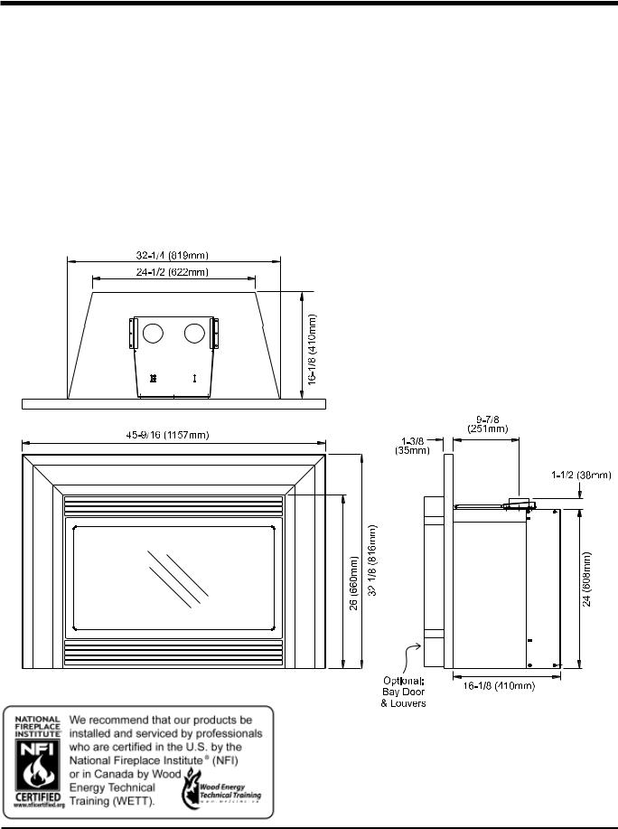
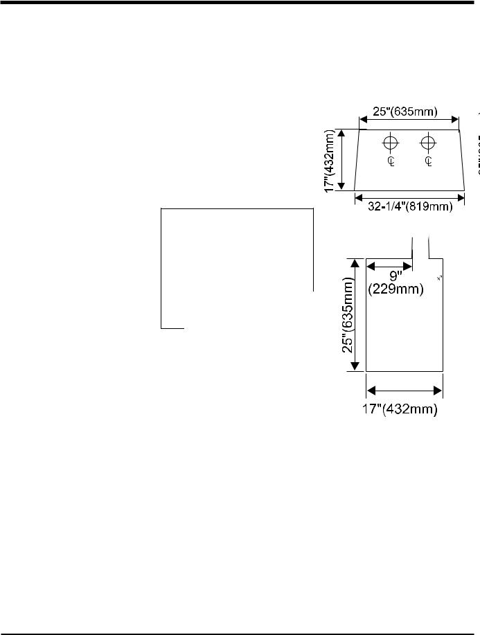
The minimum fireplace clearances & dimensionsfor the FPI gas fireplace insert are shown in the following diagrams:
Note: If you are installing the Molded Faceplate, the minimum fireplace dimensions are as follows:
Width (at front): |
34-1/2" (876mm) |
Depth: |
18" (457mm) |
Height: |
26-3/4" (679mm) |
6 |
U35 FPI Direct Vent Gas Insert |
INSTALLATION
MINIMUM CLEARANCES TO COMBUSTIBLES
|
From Unit |
Sides |
A 8" / 203 mm |
Ceiling |
B 34" / 834 mm |
From Standard Surround 31-1/8" x 44-1/8" (791mm x 1121mm)
Sides |
D 1-15/16" / 49 mm |
|
Ceiling |
E 28-7/8" / 733 mm |
|
Max. Mantel Depth G 12" / 305 mm |
|
|
Hearth Height |
H 0" / 0 mm |
|
Hearth Depth |
I 16" / 405 mm |
|
|
||
Hearth Width |
J 44" / 1118 mm |
|
Min. Alcove Width |
K 48" / 1220 mm |
|
Max. Alcove Depth L 36" / 915 mm
|
|
|
|
REGENCY BAY & FLUSH |
|
|
|
|
KENSINGTON FRONT |
||||||||||||||||||||||||||||||||||||||||||
COMBUSTIBLE MANTEL CLEARANCES |
COMBUSTIBLE MANTEL CLEARANCES |
||||||||||||||||||||||||||||||||||||||||||||||||||
|
|
|
|
|
|
|
|
|
|
|
|
|
|
|
|
|
|
|
|
|
|
|
|
|
|
|
|
|
|
|
|
|
|
|
|
|
|
|
|
|
|
|
|
|
|
|
|
|
|
|
|
|
|
|
|
|
|
|
|
|
|
|
|
|
|
|
|
|
|
|
|
|
|
|
|
|
|
|
|
|
|
|
|
|
|
|
|
|
|
|
|
|
|
|
|
|
|
|
|
|
|
|
|
|
|
|
|
|
|
|
|
|
|
|
|
|
|
|
|
|
|
|
|
|
|
|
|
|
|
|
|
|
|
|
|
|
|
|
|
|
|
|
|
|
|
|
|
|
|
|
|
|
|
|
|
|
|
|
|
|
|
|
|
|
|
|
|
|
|
|
|
|
|
|
|
|
|
|
|
|
|
|
|
|
|
|
|
|
|
|
|
|
|
|
|
|
|
|
|
|
|
|
|
|
|
|
|
|
|
|
|
|
|
|
|
|
|
|
|
|
|
|
|
|
|
|
|
|
|
|
|
|
|
|
|
|
|
|
|
|
|
|
|
|
|
|
|
|
|
|
|
|
|
|
|
|
|
|
|
|
|
|
|
|
|
|
|
|
|
|
|
|
|
|
|
|
|
|
|
|
|
|
|
|
|
|
|
|
|
|
|
|
|
|
|
|
|
|
|
|
|
|
|
|
|
|
|
|
|
|
|
|
|
|
|
|
|
|
|
|
|
|
|
|
|
|
|
|
|
|
|
|
|
|
|
|
|
|
|
|
|
|
|
|
|
|
|
|
|
|
|
|
|
|
|
|
|
|
|
|
|
|
|
|
|
|
|
|
|
|
|
|
|
|
|
|
|
|
|
|
|
|
|
|
|
|
|
|
|
|
|
|
|
|
|
|
|
|
|
|
|
|
|
|
|
|
|
|
|
|
|
|
|
|
|
|
|
|
|
|
|
|
|
|
|
|
|
|
|
|
|
|
|
|
|
|
|
|
|
|
|
|
|
|
|
|
|
|
|
|
|
|
|
|
|
|
|
|
|
|
|
|
|
|
|
|
|
|
|
|
|
|
|
|
|
|
|
|
|
|
|
|
|
|
|
|
|
|
|
|
|
|
|
|
|
|
|
|
|
|
|
|
|
|
|
|
|
|
|
|
|
|
|
|
|
|
|
|
|
|
|
|
|
|
|
|
|
|
|
|
|
|
|
|
|
|
|
|
|
|
|
|
|
|
|
|
|
|
|
|
|
|
|
|
|
|
|
|
|
|
|
|
|
|
|
|
|
|
|
|
|
|
|
|
|
|
|
|
|
|
|
|
|
|
|
|
|
|
|
|
|
|
|
|
|
|
|
|
|
|
|
|
|
|
|
|
|
|
|
|
|
|
|
|
|
|
|
|
|
|
|
|
|
|
|
|
|
|
|
|
|
|
|
|
|
|
|
|
|
|
|
|
|
|
|
|
|
|
|
|
|
|
|
|
|
|
|
|
|
|
|
|
|
|
|
|
|
|
|
|
|
|
|
|
|
|
|
|
|
|
|
|
|
|
|
|
|
|
|
|
|
|
|
|
|
|
|
|
|
|
|
|
|
|
|
|
|
|
|
|
|
|
|
|
|
|
|
|
|
|
|
|
|
|
|
|
|
|
|
|
|
|
|
|
|
|
|
|
|
|
|
|
|
|
|
|
|
|
|
|
|
|
|
|
|
|
|
|
|
|
|
|
|
|
|
|
|
|
|
|
|
|
|
|
|
|
|
|
|
|
|
|
|
|
|
|
|
|
|
|
|
|
|
|
|
|
|
|
|
|
|
|
|
|
|
|
|
|
|
|
|
|
|
|
|
|
|
|
|
|
|
|
|
|
|
|
|
|
|
|
|
|
|
|
|
|
|
|
|
|
|
|
|
|
|
|
|
|
|
|
|
|
|
|
|
|
|
|
|
|
|
|
|
|
|
|
|
|
|
|
|
|
|
|
|
|
|
|
|
|
|
|
|
|
|
|
|
|
|
|
|
|
|
|
|
|
|
|
|
|
|
|
|
|
|
|
|
|
|
|
|
|
|
|
|
|
|
|
|
|
|
|
|
|
|
|
|
|
|
|
|
|
|
|
|
|
|
|
|
|
|
|
|
|
|
|
|
|
|
|
|
|
|
|
|
|
|
|
|
|
|
|
|
|
|
|
|
|
|
|
|
|
|
|
|
|
|
|
|
|
|
|
|
|
|
|
|
|
|
|
|
|
|
|
|
|
|
|
|
|
|
|
|
|
|
|
|
|
|
|
|
|
|
|
|
|
|
|
|
|
|
|
|
|
|
|
|
|
|
|
|
|
|
|
|
|
|
|
|
|
|
|
|
|
|
|
|
|
|
|
|
|
|
|
|
|
|
|
|
|
|
|
|
|
|
|
|
|
|
|
|
|
|
|
|
|
|
|
|
|
|
|
|
|
|
|
|
|
|
|
|
|
|
|
|
|
|
|
|
|
|
|
|
|
|
|
|
|
|
|
|
|
|
|
|
|
|
|
|
|
|
|
|
|
|
|
|
|
|
|
|
|
|
|
|
|
|
|
|
|
|
|
|
|
|
|
|
|
|
|
|
|
|
|
|
|
|
|
|
|
|
|
|
|
|
|
|
|
|
|
|
|
|
|
|
|
|
|
|
|
|
|
|
|
|
|
|
|
|
|
|
|
|
|
|
|
|
|
|
|
|
|
|
|
|
|
|
|
|
|
|
|
|
|
|
|
|
|
|
|
|
|
|
|
|
|
|
|
|
|
|
|
|
|
|
|
|
|
|
|
|
|
|
|
|
|
|
|
|
|
|
|
|
|
|
|
|
|
|
|
|
|
|
|
|
|
|
|
|
|
|
|
|
|
|
|
|
|
|
|
|
|
|
|
|
|
|
|
|
|
|
|
|
|
|
|
|
|
|
|
|
|
|
|
|
|
|
|
|
|
|
|
|
|
|
|
|
|
|
|
|
|
|
|
|
|
|
|
|
|
|
|
|
|
|
|
|
|
|
|
|
|
|
|
|
|
|
|
|
|
|
|
|
|
|
|
|
|
|
|
|
|
|
|
|
|
|
|
|
|
|
|
|
|
|
|
|
|
|
|
|
|
|
|
|
|
|
|
|
|
|
|
|
|
|
|
|
|
|
|
|
|
|
|
|
|
|
|
|
|
|
|
|
|
|
|
|
|
|
|
|
|
|
|
|
|
|
|
|
|
|
|
|
|
|
|
|
|
|
|
|
|
|
|
|
|
|
|
|
|
|
|
|
|
|
|
|
|
|
|
|
|
|
|
|
|
|
|
|
|
|
|
|
|
|
|
|
|
|
|
|
|
|
|
|
|
|
|
|
|
|
|
|
|
|
|
|
|
|
|
|
|
|
|
|
|
|
|
|
|
|
|
|
|
|
|
|
|
|
|
|
|
|
|
|
|
|
|
|
|
|
|
|
|
|
|
|
|
|
|
|
|
|
|
|
|
|
|
|
|
|
|
|
|
|
|
|
|
|
|
|
|
|
|
|
|
|
|
|
|
|
|
|
|
|
|
|
|
|
|
|
|
|
|
|
|
|
|
|
|
|
|
|
|
|
|
|
|
|
|
|
|
|
|
|
|
|
|
|
|
|
|
|
|
|
|
|
|
|
|
|
|
|
|
|
|
|
|
|
|
|
|
|
|
|
|
|
|
|
|
|
|
|
|
|
|
|
|
|
|
|
|
|
|
|
|
|
|
|
|
|
|
|
|
|
|
|
|
|
|
|
|
|
|
|
|
|
|
|
|
|
|
|
|
|
|
|
|
|
|
|
|
|
|
|
|
|
|
|
|
|
|
|
|
|
|
|
|
|
|
|
|
|
|
|
|
|
|
|
|
|
|
|
|
|
|
|
|
|
|
|
|
|
|
|
|
|
|
|
|
|
|
|
|
|
|
|
|
|
|
|
|
|
|
|
|
|
|
|
|
|
|
|
|
|
|
|
|
|
|
|
|
|
|
|
|
|
|
|
|
|
|
|
|
|
|
|
|
|
|
|
|
|
|
|
|
|
|
|
|
|
|
|
|
|
|
|
|
|
|
|
|
|
|
|
|
|
|
|
|
|
|
|
|
|
|
|
|
|
|
|
|
|
|
|
|
|
|
|
|
|
|
|
|
|
|
|
|
|
|
|
|
|
|
|
|
|
|
|
|
|
|
|
|
|
|
|
|
|
|
|
|
|
|
|
|
|
|
|
|
|
|
|
|
|
|
|
|
|
|
|
|
|
|
|
|
|
|
|
|
|
|
|
|
|
|
|
|
|
|
|
|
|
|
|
|
|
|
|
|
|
|
|
|
|
|
|
|
|
|
|
|
|
|
|
|
|
|
|
|
|
|
|
|
|
|
|
|
|
|
|
|
|
|
|
|
|
|
|
|
|
|
|
|
|
|
|
|
|
|
|
|
|
|
|
|
|
|
|
|
|
|
|
|
|
|
|
|
|
|
|
|
|
|
|
|
|
|
|
|
|
|
|
|
|
|
|
|
|
|
|
|
|
|
|
|
|
|
|
|
|
|
|
|
|
|
|
|
|
|
|
|
|
|
|
|
|
|
|
|
|
|
|
|
|
|
|
|
|
|
|
|
|
|
|
|
|
|
|
|
|
|
|
|
|
|
|
|
|
|
|
|
|
|
|
|
|
|
|
|
|
|
|
|
|
|
|
|
|
|
|
|
|
|
|
|
|
|
|
|
|
|
|
|
|
|
|
|
|
|
|
|
|
|
|
|
|
|
|
|
|
|
|
|
|
|
|
|
|
|
|
|
|
|
|
|
|
|
|
|
|
|
|
|
|
|
|
|
|
|
|
|
|
|
|
|
|
|
|
|
|
|
|
|
|
|
|
|
|
|
|
|
|
|
|
|
|
|
|
|
|
|
|
|
|
|
|
|
|
|
|
|
|
|
|
|
|
|
|
|
|
|
|
|
|
|
|
|
|
|
|
|
|
|
|
|
|
|
|
|
|
|
|
|
|
|
|
|
|
|
|
|
|
|
|
|
|
|
|
|
|
|
|
|
|
|
|
|
|
|
|
|
|
|
|
|
|
|
|
|
|
|
|
|
|
|
|
|
|
|
|
|
|
|
|
|
|
|
|
|
|
|
|
|
|
|
|
|
|
|
|
|
|
|
|
|
|
|
|
|
|
|
|
|
|
|
|
|
|
|
|
|
|
|
|
|
|
|
|
|
|
|
|
|
|
|
|
|
|
|
|
|
|
|
|
|
|
|
|
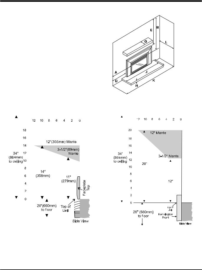
Because of the extreme heat this fireplace emits, the mantel clearances are critical.
Combustible mantel clearances from top of unit are shown in the above diagrams.
Note: A non-combustible mantel may be installed at a lower height if the framing is made of metal studs covered with a noncombustible board.
Mantel can be installed anywhere in shaded area or higher using the above scale.
Note: Ensure the paint that is used on the mantel and the facing is "heat resistant" or the paint may discolour.
U35 FPI Direct Vent Gas Insert |
7 |
|
INSTALLATION
GAS CONNECTION
GASCONNECTIONWARNING: Only persons licensed to work with gas piping may make the necessary gas connections to this appliance.
1)If the appliance is to be installed into an existing chimney system, thoroughly clean the masonry or factory built fireplace.
2)The appliance is provided with an opening on the left hand side of the control compartment. A 3/8" NPT gas supply pipe must be brought near this inlet hole.
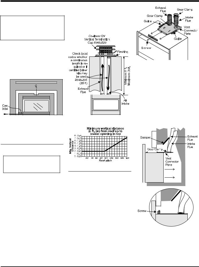
3)Locate the center point where the vent will pass through the chimney above the appliance. Move the appliance into the exact location where it is to be installed. Ensure that the Insert is level.
In areas of consistently high winds, we recommend using the Simpson Dura-Vent System
(923GK adapter and 991 high-wind cap).
The Air Intake pipe must be attached to the inlet air collar of the termination cap.
5)Install flashing.
6)Insert both liners into chimney, passing through the damper opening.
7)Install termination cap.
8)Connect the marked end of the liner to the inlet collar of the vent connector plate marked with an "I", seal connection with high temperature silicone. Secure with gear clamp.
9)Connect the 2nd liner to the exhaust collar marked with an "E", seal connection with high temperature silicone. Secure with gear clamp.
VENTING
THE APPLIANCE MUST NOT BE CONNECTED TO A CHIMNEY FLUE SERVING A SEPARATE SOLID FUEL BURNINGAPPLIANCE.
This appliance is designed to be attached to two 3" (76mm) co-linear aluminium flex running the full length of the chimney. The flue length must be a minimum length of 8 ' (2.44m) and a maximum of 35' (10.7m). See chart below for minimum distances from roof. Periodically check that the vent is unrestricted.
Masonry chimneys may take various contours which the flexible liner will accommodate. However, keep the flexible liner as straight as possible, avoid unnecessary bending.
Part # Description
948-305 3" Flex - 35 ft.
946-529 Co-linear DV Vertical
Termination Cap
Alternate Approved Caps
980 |
Vertical Termination Cap |
991 |
High Wind Cap |
923GK |
3" Co-linear Adaptor with flashing |
FLUE LINER
INSTALLATION
1)Cut the flex liner as required.
2)Mark the end of one liner to indicate Inlet.
3) Connect the other end of the above liner to the inlet side of the termination adaptor, seal connection with high temperature silicone. Secure with gear clamp.
4) Connect the 2nd liner to the exhaust side of
NOTE: 1) Final gas connection should be
the adaptor, seal connection with high
made after unit is in place to avoid
temperature silicone. Secure with gear
damage to line when pushing the unit
clamp.
into position.
2) Mill-pac may be used instead of high temperature silicone and screws may be used instead of gear clamps at connections of liner to inlet and vent collars.
8 |
U35 FPI Direct Vent Gas Insert |
INSTALLATION
GAS PIPE
PRESSURE TESTING
The appliance must be isolated from the gas supply piping system by closing its individual manual shut-off valve during any pressure testing of the gas supply piping system at test pressures equal to or less than 1/2 psig.
(3.45 kPa). Disconnect piping from valve at pressures over 1/2 psig.
The manifold pressure is controlled by a regulator built into the gas control, and should be checked at the pressure test point.
Note: To properly check gas pressure, both inlet and manifold pressures should be checked using the valve pressure ports on the valve.
1)Make sure the valve is in the "OFF" position.
2)Loosen the "IN" and/or "OUT" pressure tap(s), turning counterclockwise with a 1/ 8" wide flat screwdriver.
3)Attach manometer to "IN" and/or "OUT" pressure tap(s) using a 5/16" ID hose.
4)Light the pilot and turn the valve to "ON" position.
5)The pressure check should be carried out with the unit burning and the setting should be within the limits specified on the safety label.
6)When finished reading manometer, turn off the gas valve, disconnect the hose and tighten the screw (clockwise) with a 1/8" flat screwdriver. Note: Screw should be snug, but do not over tighten.
SIT Valve Description
1)Gas cock knob
2)Manual high/low adjustment
3)Pilot Adjustment
4)Thermocouple Connection - option
5)Outlet Pressure Tap
6)Inlet Pressure Tap
7)Pilot Outlet
8)Main Gas Outlet
9)Alternative TC Connection Point
CAUTION: Carbon will be produced if air shutter is closed too much.
Note: Any damage due to carboning resulting from improperly setting the aeration controls is NOT covered under warranty.
Note: Aeration Adjustment should only be performed by an authorized FPI Installer at the time of installation or service.
OPTIONAL
BRICK PANEL
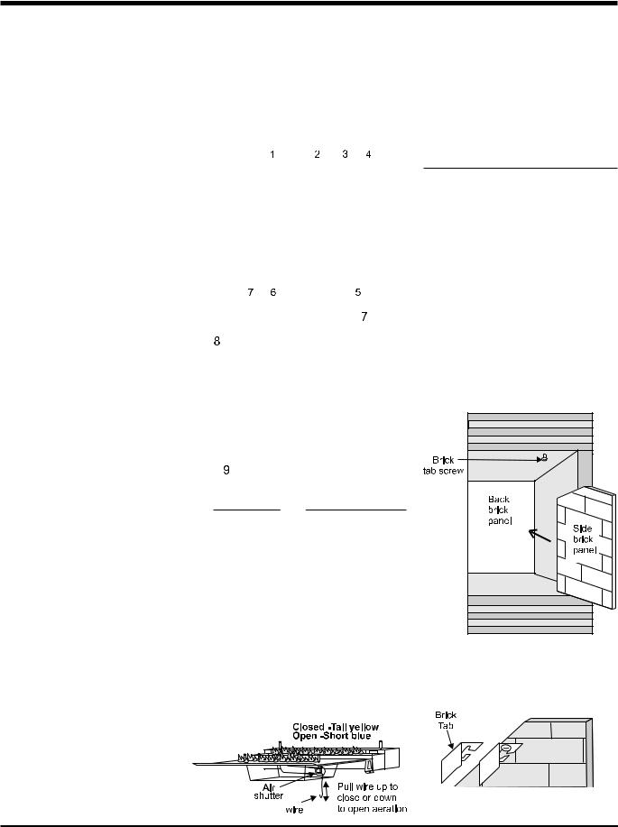
1)Unwrap the brick pattern panels from the protective wrapping.
2)Remove the glass front if it is already installed (see manual).
3)Put the rear brick panel flat against the back of the unit.
4)Before installing the side brick panels, loosen the screws for the brick tabs enough so that you can slide the brick tabs on to the screws easily but that the tabs are secure.
For the location of the side brick tab screws see diagram 1.
GAS INSERT
AERATION SYSTEM
The air shutter can be adjusted by moving the adjusting wire up or down. The wire is accessed through the bottom louver opening. Open the air shutter for a blue flame or close for a yellower flame. The burner aeration is factory set but may need adjusting due to either the local gas supply or altitude.
Minimum Air Shutter Opening:
1/8" Natural Gas
1/4" Propane
Diagram 1
5)Remove the brick tabs and slide the side brick panels into position. Install the brick tabs. See diagrams 1 and 2.
Diagram 2
U35 FPI Direct Vent Gas Insert |
9 |
|
INSTALLATION
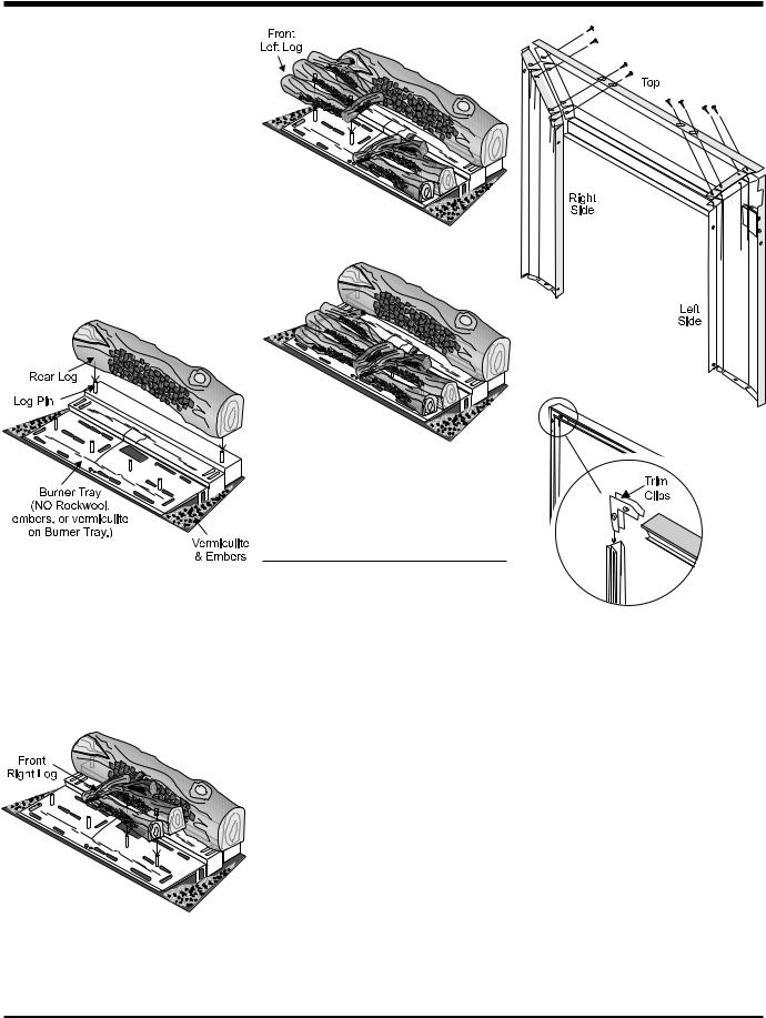
LOG INSTALLATION
WARNING: Dangerous operating conditions may occur if these logs are not positioned in their correct certified locations. Read the following instructions carefully and refer to the attached diagram.
1)Remove the logs from the box and carefully unwrap them. The logs are fragile, handle with care. Do not force into position.
2)Place the rear log on the rear log support in the back of the unit with the flat side of the log facing the back of the unit. Carefully push the log down onto the pins.
5) Test for pilot ignition.
Rear View: Faceplate Assembly
Diagram 1
6) Install the door and louvers.
NOTE: There are NO Rockwool or Large
Ember pieces used on the U35 Log
Set.
3)Sprinkle the vermiculite and ember combination on the sides of the firebox base.
4)Place the front logs in the unit, aligning the holes on the underside of the logs with the log support pins in the front of the unit. Carefully push the logs down onto the pins.
(Hint: Install the front right side first.)
FACEPLATE & TRIM
INSTALLATION
1)Lay the faceplate panels flat, face down on something soft so they don't scratch.
2)Take the top faceplate and align the holes in it with the holes in the side panels. Using the screws provided, attach from the top of the panel (the holes in the top panel are slightly larger than the holes in the side panel to facilitate easier installation). Diagram 1.
Hint: Don't tighten the screws down completely at this point, continue on with steps 3 and 4 and do a trial fit to the unit. Make any necessary adjustments and when it fits properly then tighten down the screws.
3)Using the connectors provided, join the left side trim (with the ON/OFF switch) to the top trim. Diagram 2. Connect the right side trim to the top trim.
4)Place the trim on the assembled faceplate panels, aligning the wire connections from the switches with the notch on the left side panel.
Rear View: Trim Assembly
Diagram 2
5)Connect the fan switch wires by taking the black and red wires with the male ends (in the grey harness) and connect them with the wire connectors from the fan speed control.
6)Connect the ON/OFF switch wires by taking the black and red wires with the female ends and connect them to the ON/OFF switch.
7)Tuck the wires into the faceplate to keep them away from the insert using the clip provided. Attach the clip to the rear of the faceplate to ensure that the wires do not touch the side of the unit.
Diagram 3.
8)The power cord should be run behind the faceplate panel.
10 |
U35 FPI Direct Vent Gas Insert |
 Loading...