


www.regency-fire.com |
P42 Gas Fireplace |
Owners & |
|
Installation Manual |
MODELS: P42-NG4 Natural Gas P42-LP4 Propane
WARNING: |
|
|
FOR YOUR SAFETY |
|
|
Iftheinformationintheseinstructionsarenotfollowedexactly, |
What to do if you smell gas: |
|
|||
a fire or explosion may result causing property damage, |
Do not try to light any appliance |
||||
personal injury or loss of life. |
Do not touch any electrical switch: |
||||
|
|
|
do not use any phone in your |
||
FOR YOUR SAFETY |
|||||
building. |
|
||||
Do not store or use gasoline or other flammable vapors and |
Immediately call your gas supplier |
||||
liquids in the vicinity of this or any other appliance. |
from a neighbour's phone. Follow |
||||
Installation and service must be performed by a qualified |
the gas supplier's instructions. |
||||
If you cannot reach your |
gas |
||||
installer, service agency or the gas supplier. |
|||||
supplier, call the fire department. |
|||||
|
|
|
|||
Tested by: |
|
Installer: Please complete the details on the back cover |
|
||
|
|
|
|||
|
|
and leave this manual with the homeowner. |
|
||
|
|
Homeowner: Please keep these instructions for future reference. |
|
||
|
|
|
|
||
918-523a |
FPI FIREPLACE PRODUCTS INTERNATIONAL LTD. 6988 Venture St., Delta, BC Canada, V4G 1H4 |
03/06/08 |
|||
To the New Owner:
Congratulations!
You are the owner of a state-of-the-art Gas Fireplace by FIREPLACE PRODUCTS INTERNATIONAL. The P42 is a hand crafted appliance and has been designed to provide you with all the warmth and charm of a wood fi replace at the fl ick of a switch. The model P42 has been approved by Warnock Hersey for both safety and efficiency. As it also bears our own mark, it promises to provide you with economy, comfort and security for many trouble free years to follow. Please take a moment now to acquaint yourself with these instructions and the many features of your Regency® Fireplace.
INFORMATION FOR MOBILE/MANUFACTURED HOMES AFTER FIRST SALE
This Regency® product has been tested and listed by Warnock Hersey as a Vented Gas Fireplace Heater to the following standards:
UL307B-1995, CAN/CGA-2.17-M91, ANSI Z21.88b-2003/CSA 2.33b-2003.
This Direct Vent System Appliance must be installed in accordance with the manufacturer's installation instructions and the Manufactured Home Construction and Safety Standard, Title 24 CFR, Part 3280, or the current Standard of Fire Safety Criteria for Manufactured Home Installations, Sites, and Communities ANSI/NFPA 501A, and with CAN/CSA Z240-MH Mobile Home Standard in Canada.
This appliance installation must comply with the manufacturer's installation instructions and local codes, if any. In the absence of local codes follow the current National Fuel Gas Code, ANSI Z223.1 and the current National Electrical Code ANSI/NFPA 70 in the U.S.A., and the current CAN/CGA B149 Gas Installation Code and the current Canadian Electrical Code CSA C22.1 in Canada.
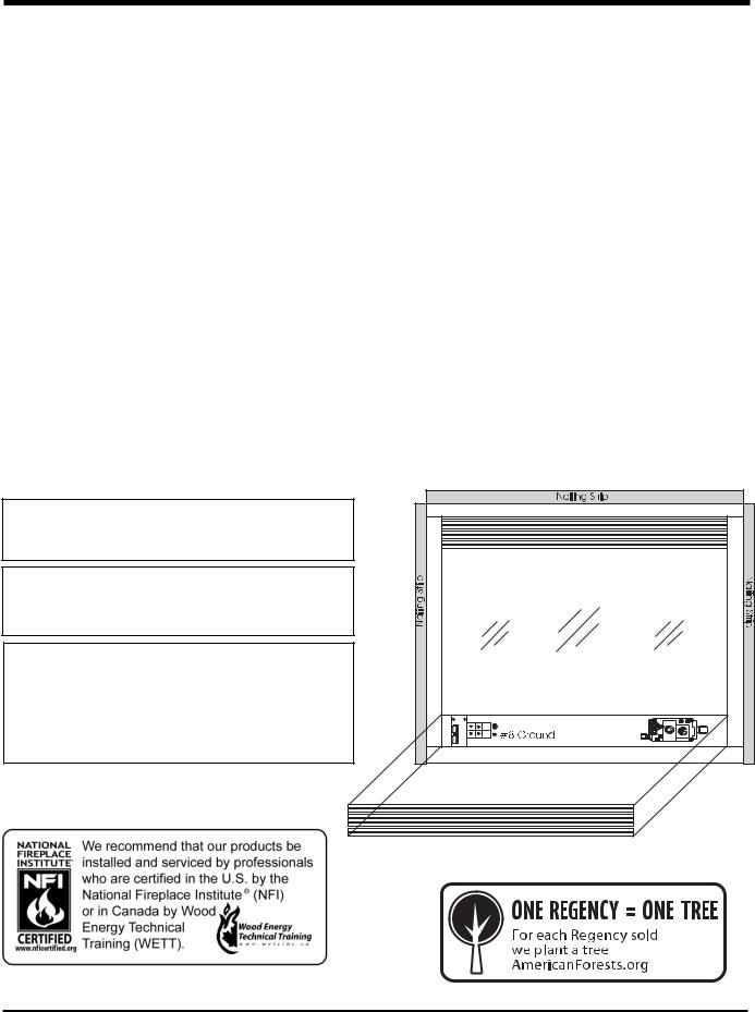
This Regency® Mobile/Manufactured Home Listed appliance comes factory equipped with a means to secure the unit.
This Regency® Mobile/Manufactured Home listed appliance comes equipped with a dedicated #8 ground lug to which an 18 gauge copper wire from the steel chassis ground must be attached.
This appliance may be installed in an aftermarket permanently located, manufactured (mobile) home, where not prohibited by local codes.
This appliance is only use with the type of gas indicated on the rating plate. This appliance is not convertible for use with other gases, unless a certified kit is used.
2 |
Regency® P42-4 Zero Clearance Direct Vent Gas Fireplace |

TABLE OF CONTENTS
SAFETY LABEL |
|
OPERATING INSTRUCTIONS |
|
|
Copy of Safety Decal..................................................... |
4 |
Optional Remote Control............................................. |
34 |
|
|
|
Optional Wall Switch.................................................... |
34 |
|
REQUIREMENTS |
|
Optional Wall Thermostat ........................................... |
34 |
|
|
|
Operating Instructions ................................................. |
34 |
|
MA Code - CO Detector |
5 |
Lighting Procedure ...................................................... |
34 |
|
Copy Of The Lighting Plate Instructions |
35 |
|||
|
|
INSTALLATION |
MAINTENANCE |
|
Important Message ...................................................... |
6 |
Before You Start ............................................................ |
6 |
General Safety Information ........................................... |
6 |
Installation Checklist...................................................... |
6 |
Manufactured Mobile Home Additional Requirements .. |
7 |
Locating Your Gas Fireplace ......................................... |
7 |
Unit Specifi cations......................................................... |
7 |
Heatwave Optional Duct System Kit#946-556 ............. |
7 |
Optional Hearth ............................................................. |
7 |
Clearances .................................................................... |
8 |
Mantels.......................................................................... |
8 |
Mantel Leg Clearances ................................................. |
8 |
Framing And Finishing................................................... |
9 |
Top Assembly & Nailing Strips....................................... |
9 |
Venting Introduction....................................................... |
9 |
Vent Restrictor............................................................... |
9 |
Exterior Vent Termination Requirements..................... |
10 |
Venting ........................................................................ |
11 |
4” x 6-5/8” Rigid Pipe Cross Reference Chart............. |
12 |
Rigid Pipe Venting ....................................................... |
14 |
Horizontal Terminations.............................................. |
15 |
Vertical Terminations ................................................... |
17 |
Installation Procedures................................................ |
23 |
High Elevation ............................................................. |
24 |
Gas Line Installation.................................................... |
24 |
Gas Pipe Pressure Testing.......................................... |
24 |
Aeration Adjustment .................................................... |
25 |
Brick Panels ................................................................ |
25 |
Log Set Installation...................................................... |
26 |
Standard Flush Door ................................................... |
27 |
Flush Louvers.............................................................. |
27 |
Double Screen Doors ................................................. |
27 |
Optional Bay Door ....................................................... |
28 |
Bay Louvers ................................................................ |
28 |
Full Screen doors ........................................................ |
29 |
Wiring Diagrams ......................................................... |
32 |
Normal Operating Sounds Of Gas Appliances ............ |
36 |
Shutdown Procedure................................................... |
36 |
First Fire ...................................................................... |
36 |
Maintenance Instructions ............................................ |
36 |
Gold-Plated Louvers.................................................... |
37 |
Log Replacement ........................................................ |
37 |
Thermopile / Thermocouple......................................... |
37 |
Glass Replacement ..................................................... |
37 |
Door Glass .................................................................. |
37 |
Removing The Fan...................................................... |
38 |
Replacing The Fan ...................................................... |
38 |
Removing Valve........................................................... |
38 |
Installing Valve............................................................. |
39 |
PARTS LIST |
|
Main Assembly ............................................................ |
40 |
Burner & Log Assembly............................................... |
41 |
Flush Door & Louvers.................................................. |
42 |
Bay Front & Louvers.................................................... |
43 |
WARRANTY |
|
Warranty ...................................................................... |
47 |
Regency® P42-4 Zero Clearance Direct Vent Gas Fireplace |
3 |

SAFETY LABEL
This is a copy of the label that accompanies each P42 Zero Clearance
Direct Vent Gas Fireplace. We have printed a copy of the contents here for your review. The safety label is located on the front inside base of the unit, visible when the bottom louver is open.
NOTE: Regency® units are constantly being improved. Check the label on the unit and if there is a difference, the label on the unit is the correct one.
COPY OF SAFETY DECAL FOR P42
For the State of Massachusetts, installation and repair must be done by a plumber or gasfi tter licensed in the Commonwealth of
Massachusetts.
For the State of Massachusetts, fl exible connectors shall not exceed 36 inches in length.
For the State of Massachusetts, the appliances individual manual shut-off must be a t-handle type valve.
The State of Massachusetts requires the installation of a carbon monoxide alarm in accordance with NFPA 720 and a CO alarm with battery back up in the same room where the gas appliance is installed.
4 |
Regency® P42-4 Zero Clearance Direct Vent Gas Fireplace |

REQUIREMENTS
MA Code - CO Detector
(for the State of Massachusetts only)
5.08: Modifications to NFPA-54, Chapter 10
(2) Revise 10.8.3 by adding the following additional requirements:
(a) For all side wall horizontally vented gas fueled equipment installed in every dwelling, building or structure used in whole or in part for residential purposes, including those owned or operated by the Commonwealth and where the side wall exhaust vent termination is less than seven (7) feet above finished grade in the area of the venting, including but not limited to decks and porches, the following requirements shall be satisfied:
1. INSTALLATION OF CARBON MONOXIDE DETECTORS. At the time of installation of the side wall horizontal vented gas fueled equipment, the installing plumber or gasfitter shall observe that a hard wired carbon monoxide detector with an alarm and battery back-up is installed on the floor level where the gas equipment is to be installed. In addition, the installing plumber or gasfitter shall observe that a battery operated or hard wired carbon monoxide detector with an alarm is installed on each additional level of the dwelling, building or structure served by the side wall horizontal vented gas fueled equipment. It shall be the responsibility of the property owner to secure the services of qualified licensed professionals for the installation of hard wired carbon monoxide detectors
a.In the event that the side wall horizontally vented gas fueled equipment is installed in a crawl space or an attic, the hard wired carbon monoxide detector with alarm and battery back-up may be installed on the next adjacent floor level.
b.In the event that the requirements of this subdivision can not be met at the time of completion of installation, the owner shall have a period of thirty (30) days to comply with the above requirements; provided, however, that during said thirty (30) day period, a battery operated carbon monoxide detector with an alarm shall be installed.
2.APPROVED CARBON MONOXIDE DETECTORS. Each carbon monoxide detector as required in accordance with the above provisions shall comply with NFPA 720 and be ANSI/UL 2034 listed and IAS certified.
3.SIGNAGE. A metal or plastic identification plate shall be permanently mounted to the exterior of the building at a minimum height of eight
(8) feet above grade directly in line with the exhaust vent terminal for the horizontally vented gas fueled heating appliance or equipment. The sign shall read, in print size no less than one-half (1/2) inch in size, "GAS VENT DIRECTLY BELOW. KEEP CLEAR OF ALL
OBSTRUCTIONS".
4. INSPECTION. The state or local gas inspector of the side wall horizontally vented gas fueled equipment shall not approve the installation unless, upon inspection, the inspector observes carbon monoxide detectors and signage installed in accordance with the provisions of 248 CMR 5.08(2)(a)1 through 4.
(b) EXEMPTIONS: The following equipment is exempt from 248 CMR 5.08(2)(a)1 through 4:
1.The equipment listed in Chapter 10 entitled "Equipment Not Required To Be Vented" in the most current edition of NFPA 54 as adopted by the Board; and
2.Product Approved side wall horizontally vented gas fueled equipment installed in a room or structure separate from the dwelling, building or structure used in whole or in part for residential purposes.
(c) MANUFACTURER REQUIREMENTS - GAS EQUIPMENT VENTING SYSTEM PROVIDED. When the manufacturer of Product Approved side wall horizontally vented gas equipment provides a venting system design or venting system components with the equipment, the instructions provided by the manufacturer for installation of the equipment and the venting system shall include:
1.Detailed instructions for the installation of the venting system design or the venting system components; and
2.A complete parts list for the venting system design or venting system.
(d) MANUFACTURER REQUIREMENTS - GAS EQUIPMENT VENTING SYSTEM NOT PROVIDED. When the manufacturer of a Product Approved side wall horizontally vented gas fueled equipment does not provide the parts for venting the flue gases, but identifies "special venting systems", the following requirements shall be satisfied by the manufacturer:
1.The referenced "special venting system" instructions shall be included with the appliance or equipment installation instructions; and
2.The "special venting systems" shall be Product Approved by the Board, and the instructions for that system shall include a parts list and detailed installation instructions.
(e) A copy of all installation instructions for all Product Approved side wall horizontally vented gas fueled equipment, all venting instructions, all parts lists for venting instructions, and/or all venting design instructions shall remain with the appliance or equipment at the completion of the installation.
Regency® P42-4 Zero Clearance Direct Vent Gas Fireplace |
5 |
INSTALLATION
IMPORTANT MESSAGE
SAVE THESE
INSTRUCTIONS
TheP42-NG/P42-LPDirect Vent Fireplace must beinstalledinaccordancewiththeseinstructions.
Carefully read all the instructions in this manual
first.Consultthe"authorityhavingjurisdiction"to determine the need for a permit prior to starting the installation. It is the responsibility of the installer to ensure this fi replace is installed in compliancewithmanufacturersinstructionsand all applicable codes.
BEFORE YOU START
Safe installation and operation of this appliance requires common sense, however, we are required by the Canadian Safety Standards and ANSI Standards to make you aware of the following:
INSTALLATION AND REPAIR SHOULD BE DONE BY AN AUTHORIZED SERVICE PERSON. THE APPLIANCE SHOULD BE INSPECTED BEFORE USE AND AT LEAST ANNUALLY BY A PROFESSIONALSERVICEPERSON. MORE FREQUENT CLEANING MAY BEREQUIREDDUETOEXCESSIVE LINTFROMCARPETING,BEDDING MATERIAL, ETC. IT IS IMPERATIVE THATCONTROLCOMPARTMENTS, BURNERS AND CIRCULATING AIR PASSAGEWAYS OF THE APPLIANCE BE KEPT CLEAN.
DUETOHIGHTEMPERATURES,THE APPLIANCESHOULDBELOCATED OUT OF TRAFFICANDAWAY FROM FURNITURE AND DRAPERIES.
WARNING: FAILURE TO INSTALL THISAPPLIANCECORRECTLYWILL VOID YOUR WARRANTY AND MAY CAUSE A SERIOUS HOUSE FIRE.
CHILDREN AND ADULTS SHOULD BEALERTED TO THE HAZARDS OF HIGH SURFACE TEMPERATURES, ESPECIALLY THE FIREPLACE GLASS, AND SHOULD STAY AWAY TO AVOID BURNS OR CLOTHING IGNITION.
YOUNG CHILDREN SHOULD BE CAREFULLY SUPERVISED WHEN THEY ARE IN THE SAME ROOM AS THE APPLIANCE.
CLOTHINGOROTHERFLAMMABLE MATERIALSHOULDNOTBEPLACED ON OR NEAR THE APPLIANCE.
GENERAL SAFETY INFORMATION
1)The appliance installation must conform with local codes or, in the absence of local codes,withthecurrentCanadianorNational Gas Codes, CAN1-B149 or ANSI Z223.1
Installation Codes.
2)The appliance when installed, must be electrically grounded in accordance with local codes, or in the absence of local codes with the current National Electrical Code,
ANSI/NFPA 70 or CSA C22.1 Canadian Electrical Code.
3)See general construction and assembly instructions. The appliance and vent should be enclosed.
4)This appliance must be connected to the specifi ed vent and termination cap to the outside of the building envelope. Never vent to another room or inside a building. Make sure that the vent is fi tted as per Venting instructions.
5)Inspect the venting system annually for blockage and any signs of deterioration.
6)Venting terminals shall not be recessed into a wall or siding.
7)Any safety glass removed for servicing must be replaced prior to operating the appliance.
8)To prevent injury, do not allow anyone who is unfamiliar with the operation to use the fi replace.
9)Wearglovesandsafetyglassesforprotection while doing required maintenance.
10)Be aware of electrical wiring locations in walls and ceilings when cutting holes for termination.
11)Under no circumstances should this appliance be modifi ed. Parts that have to be removed for servicing should be replaced prior to operating this appliance.
12)Installation and any repairs to this appliance should be done by an authorized service person.Aprofessionalservicepersonshould be called to inspect this appliance annually.
Make it a practice to have all of your gas appliances checked annually.
13)Do not slam shut or strike the glass door.
14)Under no circumstances should any solid fuels (wood, paper, cardboard, coal, etc.) be used in this appliance.
15)The appliance area must be kept clear and free of combustible materials, (gases and other fl ammable vapours and liquids).
Emissions from burning wood or gas could contain chemicals known to the State of
California to cause cancer, birth defects or other reproductive harm.
INSTALLATION
CHECKLIST
1)Locate appliance, refer to the following sections:
a)Locating Your Gas Fireplace
b)Clearances
c)Mantels
d)Mantels Legs Clearance
e)Framing and Finishing
2)Assemble Top Facing Support and Side Nailing Strips, see the "Top Assembly & Nailing Strips" section. NOTE: must be done before installing unit into fireplace.
3)Install venting, refer to the "Venting" section.
4)Make gas and electrical connections. Test the pilot. Must be as per diagram. See the "Pilot Adjustment" section.
5)Test Gas Pressure. Refer to the "Gas Pipe
Pressure Testing" section.
6)Install standard and optional features. Refer to the following sections where applicable:
a. Brick Panels b. Log Set
c. Standard Flush Door d. Flush Louvers
e. Double Screen Door f. Bay Door
g. Bay Louvers
h. Full Screen Front i. Remote Control j. Wall Switch
k. Wall Thermostat
11) Final check.
Before leaving this unit with the customer, the installer must ensure that the appliance is fi ring correctly and operation fully explained to customer.
6 |
Regency® P42-4 Zero Clearance Direct Vent Gas Fireplace |
INSTALLATION
This includes:
1)Clockingtheappliancetoensurethecorrect
fi ring rate (rate noted on label 35,000 Btu/h) after burning appliance for 15 minutes.
2)If required, adjusting the primary air to ensure that the fl ame does not carbon.
First allow the unit to burn for 15-20 min. to stabilize.
CAUTION:Any alteration to the product that causes sooting or carboning that results in damage is not the responsibility of the
manufacturer.
MANUFACTURED
MOBILE HOME
ADDITIONAL
REQUIREMENTS
1)Ensure that structural members are not cut or weakened during installation.
2)Ensure proper grounding using the #8 ground lug provided. See the "Wiring
Diagram" section.
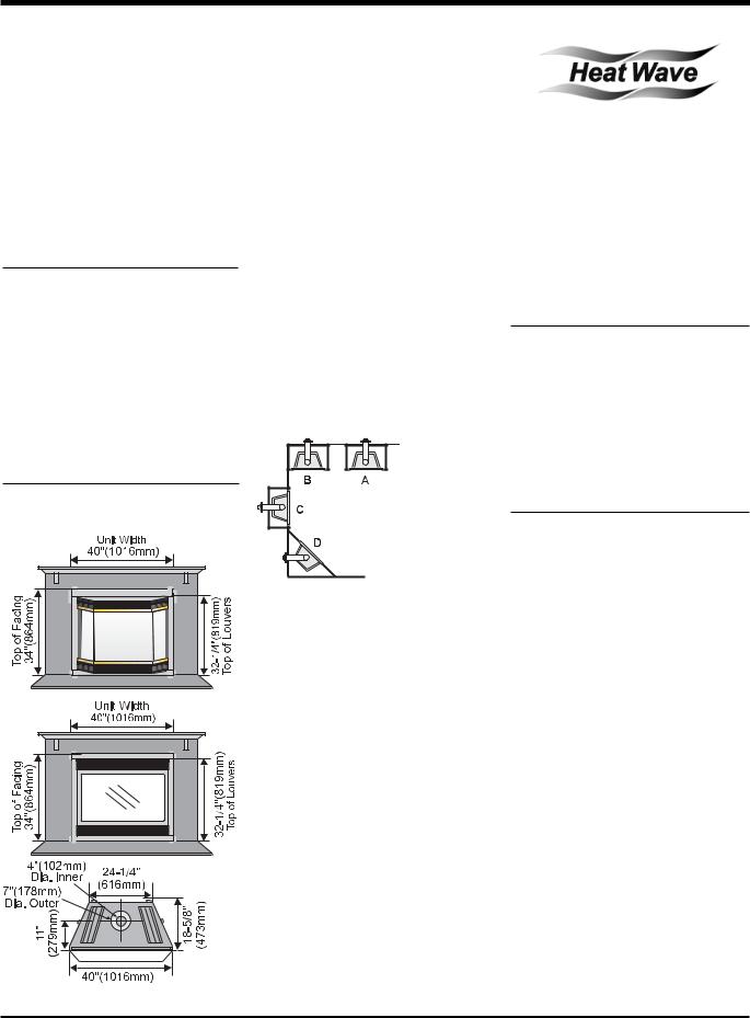
UNIT SPECIFICATIONS
LOCATING YOUR
GAS FIREPLACE
1)When selecting a location for your stove, ensure that the clearances outlined on this page are met.
2)Provide adequate clearances for servicing.
3)The appliance must be installed on a fl at, solid, continuous surface (e.g. wood, metal, concrete).This may be the fl oor, or raised up on a platform to enhance its visual impact.
If the appliance is going to be installed on carpeting, combustible linoleum tile or other combustible material other than wood flooring,theappliancemustbeinstalledona metal or wood panel extending the full width and depth of the appliance.
4)The P42 Direct Vent Gas Fireplace can be installedinarecessedpositionorframedout into the room as in A, B, C, D. See Diagram
1.
Diagram 1
A) Flat on Wall
B)Flat on Wall Corner
C)Recessed into
Wall/Alcove
D) Corner
5)This appliance is Listed for bedroom installationswhenusedwithaListedMillivolt Thermostat. Some areas may have further requirements, check local codes before installation.
6)The P42 Direct Vent Gas Fireplace is approved for alcove installations, which meet the clearances listed on this page.
7)Werecommendthatyouplanyourinstallation on paper using exact measurements for clearances and fl oor protection before actually installing this appliance. Have an authorized inspector, dealer, or installer review your plans before installation.
Note: For vent terminations see the "ExteriorVentTerminationLocations" section.
OPTIONAL DUCT SYSTEM KIT #946-556
The HeatWave Air Duct Kit increases the effectiveness of your fi replace by dispersing warmairfromthefireplacetoremotelocationsin the same room or other rooms in your home.
Up to two kits may be installed on the fi replace. Please Note: Only 1 HeatWave kit may be operated at one time. This includes the internal blower option as well.
OPTIONAL
HEAT RELEASE KIT #946-570
The Heat Release Kit expels warm air from the fi replace to the outside of the building, allowing the fi replace to be operated with less heat entering the room. The kit may be used on either the left or right side.
HEARTH
A hearth is not mandatory, but is recommended for aesthetics and for added safety.
Regency® P42-4 Zero Clearance Direct Vent Gas Fireplace |
7 |
INSTALLATION
CLEARANCES |
MANTELS |
The clearances listed below are Minimum distances unless otherwise stated:
A major cause of chimney related fires is failure to maintain required clearances (air space) to combustible materials. It is of the greatest importance that this fireplace and vent system be installed only in accordance with these instructions.
Clearance to Combustibles from: Back 0" (0mm)
Side 0" (0mm) Floor 0" (0mm)
Minimum Clearance from Louver to:
Mantel |
min. 7" |
(177mm) |
|
||||||||||
Ceiling |
36" |
(914mm) from top |
|
||||||||||
|
|
|
|
|
|
of louvers |
|
||||||
Side Wall |
6" |
|
(152mm) |
|
|||||||||
Vent |
1-1/2" |
(38mm) Flex |
|
||||||||||
|
|
|
|
1-1/4" |
(32mm) Rigid Pipe |
|
|||||||
Alcove Clearances: |
|
|
|
|
|
|
|
|
|||||
Max. Depth |
36" |
(914mm) |
|
||||||||||
Min. Width |
52" |
(1321mm) |
|
||||||||||
Min. Height |
90" |
(2286mm) |
|
||||||||||
|
|
|
|
|
|
|
|
|
|
|
|
|
|
|
|
|
|
|
|
|
|
|
|
|
|
|
|
|
|
|
|
|
|
|
|
|
|
|
|
|
|
|
|
|
|
|
|
|
|
|
|
|
|
|
|
|
|
|
|
|
|
|
|
|
|
|
|
|
|
|
|
|
|
|
|
|
|
|
|
|
|
|
|
|
|
|
|
|
|
|
|
|
|
|
|
|
|
|
|
|
|
|
|
|
|
|
|
|
|
|
|
|
|
|
|
|
|
|
|
|
|
|
|
|
|
|
|
|
|
|
|
|
|
|
|
|
|
|
|
WARNING
Fire hazard is an extreme risk if these clearances are
not adhered to.
The HeatWave Duct Kit
and the Heat Release
Kit have different clearance and framing
Heat Release Kit requirements, check theHeatWaveandHeat
Release manual for details.
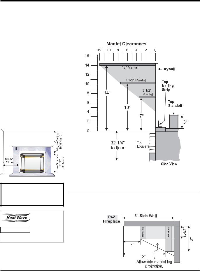
Because of the extreme heat this fireplace emits, the mantel clearances are critical.
Combustible mantel clearances from louver are shown in the diagram below.
Note: A non-combustible mantel may be installed at a lower height if the framing is made of metal studs covered with a non-combustible board.
This drawing is to scale at 1:6 (one inch = 6 inches)
Mantel can be installed anywhere in shaded area using the above scale for units with the Flush Front and with the optional Bay Front.
Note: Ensure the paint that is used on the mantel and the facing is "heat resistant" or the paint may discolour.
MANTEL LEG CLEARANCES
Combustible mantel leg clearances as per diagram below:
Maximum
1-1/2" projection at 2" minimum clearance.
8 |
Regency® P42-4 Zero Clearance Direct Vent Gas Fireplace |
INSTALLATION
FRAMING AND
FINISHING
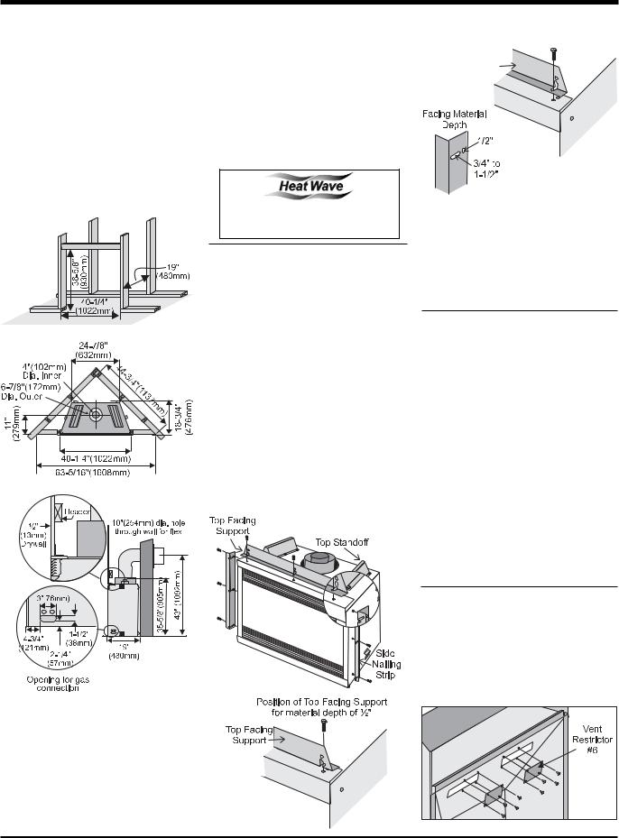
1)Determine the total thickness of facing material (ie. drywall plus ceramic tiles) to allow the fi nished surface to be fl ush with the front of the unit. Total facing thickness canvaryfrom1/2"(13mm)to1-1/4"(32mm) thick.
2)Frame in the enclosure for the unit with framing material. The framed opening for the assembled kit is 36-5/8" high x 40-1/4" wide x 19" deep (930mm H x 1022mm W x 483mm D). See Diagram 1.
Diagram 1
5)The unit does not have to be completely enclosed in a chase. The clearance on top of the unit from the top standoffs is 0" so combustible building materials can be laid directly on top of the standoffs. You must maintain these clearances from the vent to combustible materials: Flex Termination clearance1-1/2"(38mm),SimpsonDura-Vent clearance or (1-1/4" (32mm). Combustible materials can be laid against the side and back standoffs and the fi replace base.
The HeatWave Duct Kit has different clearance and framing requirements, check the HeatWave manual for details.
TOP ASSEMBLY &
NAILING STRIPS
The Top Facing Support and Side Nailing Strips mustbecorrectlypositionedandattachedbefore the unit is slipped into position.
1)The top standoffs are shipped installed.
2)The Top Facing Support and the 2 Side Nailing Strips can be installed at different depthsdependingonthewidthofyourfacing.
Match the depths of the top facing support and the side nailing strips.
a)Mount Top Facing Support using the 3 supplied screws into the 3 pre-punched screw holes on the top front of the unit.
See Diagrams 2 & 3 for the proper position of the Top Facing Support for the various material depths.
Position of Top Facing Support for material depth of 3/4” to 1-1/2"
Top Facing
Support
Diagram 3
Diagram 4
b)Mount the Side Nailing Strip using the 3 supplied screws into the 3 screw holes or slots (diagram 4) on the side of the unit and repeat for the other side. Use the hole for a 1/2" (13mm) thick facing material and the slot for a range of thickness from 3/4" to 1-1/2" (25mm to 38mm).
VENTING
INTRODUCTION
The P42 uses the "balanced fl ue" technology Co-Axial system. The inner liner vents products of combustion to the outside while the outer liner draws outside combustion air into the combustion chamber thereby eliminating the need to use heated room air for combustion and losing warm room air up the chimney.
Note: These flue pipes must not be connected to any other appliance.
The gas appliance and vent system must be vented directly to the outside of the building, and never be attached to a chimney serving a separate solid fuel or gas burning appliance. Eachdirectventgasappliancemustuseit'sown separate vent system. Common vent systems are prohibited.
VENT RESTRICTOR
A vent restrictor may be required. Check the diagrams in the "Rigid Pipe Venting
Arrangements" section to determine if the #6 restrictor is needed for your vent confi guration.
Diagram 1
If required, attach the 2 piece #6 restrictor using 4 screws per piece to the inside top of the fi rebox.
Note: 43"(1092mm)istheminimumheight |
|
|
|
for flex termination and Rigid Pipe |
|
|
terminations. |
|
3) For exterior walls, insulate the enclosure to |
|
|
|
the same degree as the rest of the house, |
|
|
apply vapour barrier and drywall, as per |
|
|
local installation codes. (Do not insulate |
|
|
the fireplace itself.) |
|
4) |
The top louvers must not be closer than |
|
|
36" (914mm) to the ceiling. |
Diagram 2 |
Regency® P42-4 Zero Clearance Direct Vent Gas Fireplace |
9 |
|
10
Fireplace Gas Vent Direct Clearance Zero 4-P42 ®Regency
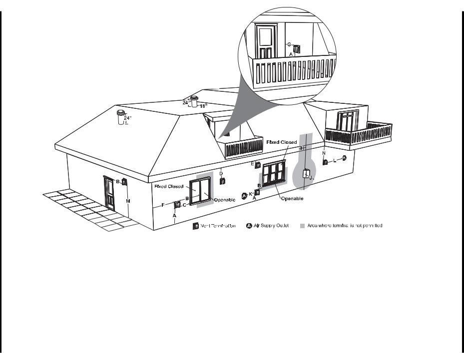
A= Clearance above grade, veranda, porch, deck, or balcony *(min. 12"/30cm) B= Clearance to window or door that may be opened *(12"/30cm)
C= Clearance to permanently closed window *(min. 12"/30cm)
D= Vertical clearance to ventilated soffit located above the terminal within a horizontal distance of (24"/60cm) from the centerline of the terminal (min. 18"/46cm) check with local code.
E= Clearance to unventilated soffit (min. 15"/38cm)
F= Clearance to outside corner: with AstroCap Termination Cap (min 6"/15cm), with Dura-
Vent Termination Cap (13"/33cm)
G= Clearance to inside corner: with AstroCap Termination Cap (min 6"/15cm), with DuraVent Termination Cap (12"/30cm)
H= Not to be installed above a meter/regulator assembly within (3'/90cm) horizontally from the centerline of the regulator.
J= Clearance to service regulator vent outlet *(min 36"/90cm)
K= Clearance to non-mechanical air supply inlet to building or the combustion air inlet to any other appliance *(12"/30cm)
L= Clearance to a mechanical air supply inlet *(min. 72"/1.8m)
M= Clearance above paved sidewalk or a paved driveway located on public property
*(min. 84"/2.1m)
N= Clearance under veranda, porch, deck, or balcony *(min. 12"/30cm)
Note:
-A vent shall not terminate directly above a sidewalk or paved driveway which is located between two single family dwellings and serves both dwellings.
-Only permitted if veranda, porch, deck, or balcony is fully open on a minimum of two sides beneath the floor.
-If the vent termination is accessible, a certified guard shall be installed.
* As specified in CGA B149 Installation Code. Note: Local codes or regulations may require different clearances.
REQUIREMENTS TERMINATION VENT EXTERIOR
INSTALLATION
INSTALLATION
VENTING
Regency® Direct Vent System (Flex) Horizontal Terminations Only
These venting systems, in combination with the P42 Direct Vent Gas |
1) |
6-7/8" dia. fl exible liner (4 ft. length) |
Fireplace, have been tested and listed as a direct vent heater system |
2) |
4" dia. fl exible liner (4 ft. length) |
by Warnock Hersey. The location of the termination cap must conform to |
3) |
spring spacers (4) |
the requirements in the Vent Terminal Locations diagram in the "Exterior |
4) |
thimble (2) |
Vent Termination Locations" section. |
5) |
AstroCap termination cap (1) |
|
6) |
screws (12) |
Regency® Direct Vent (Flex) System Termination Kit (Part # 946-515) |
7) |
tube of Mill Pac (1) |
includes all the parts needed to install the P42 with a maximum |
8) |
plated screws (8) |
run of 4 feet. |
9) |
screws #8 x 1/2" Drill Point, stainless steel (4) |
Wall Thimble (2 pc)
4" (102mm) |
AstroCap |
|
dia. flue pipe |
Termination Cap |
|
6-7/8" |
Part #946-523/P |
|
|
||
(173mm) dia. |
spring |
|
Flue pipe |
||
spacer |
||
|
If longer runs are needed, the Regency® Direct Vent system (Flex)
# 946-516 includes all the parts needed to install the P42 with a maximum 10' run.
1)6-7/8" dia. fl exible liner (10 ft. length)
2)4" dia. fl exible liner (10 ft. length)
3)spring spacers (7)
4)thimble (2)
5)AstroCap termination cap (1)
6)screws (12)
7)tube of Mill Pac (1)
8)plated screws (8)
9)screws #8 x 1/2" Drill Point, stainless steel (4)
Note:
a)Liner sections should be continuous without any joints or seams.
b)Only Flex pipe purchased from Regency® may be used for Flex
Installations.
Regency® P42-4 Zero Clearance Direct Vent Gas Fireplace |
11 |

INSTALLATION
4” X 6-5/8” RIGID PIPE CROSS REFERENCE CHART
Components from different Manufacturers may not be mixed. Not All Rigid Pipe components are available directly from FPI.
|
Description |
Simpson |
Simpson |
Selkirk |
American Metal |
Metal-Fab® |
Security |
||
|
Direct Vent GS® |
Products |
® |
||||||
|
Direct Vent Pro® |
Discontinued |
Direct-Temp™ |
|
Sure Seal |
Secure Vent® |
|||
|
|
|
|
Amerivent Direct |
|
|
|
||
|
6” Pipe Length, Galvanized |
46DVA-06 |
908 |
4DT-6 |
N/A |
|
4D6 |
SV4L6 |
|
|
6” Pipe Length, Black |
46DVA-06B |
908B |
4DT-6B |
N/A |
|
4D6B |
SV4LB6 |
|
|
7” Pipe Length, Galvanized |
N/A |
N/A |
N/A |
4D7 |
|
N/A |
N/A |
|
|
7” Pipe Length, Black |
N/A |
N/A |
N/A |
4D7B |
|
N/A |
N/A |
|
|
9” Pipe Length, Galvanized |
46DVA-09 |
907 |
4DT-9 |
N/A |
|
N/A |
N/A |
|
|
9” Pipe Length, Black |
46DVA-09B |
907B |
4DT-9B |
N/A |
|
N/A |
N/A |
|
|
12” Pipe Length, Galvanized |
46DVA-12 |
906 |
4DT-12 |
4D12 |
|
4D12 |
SV4L12 |
|
|
12” Pipe Length, Black |
46DVA-12B |
906B |
4DT-12B |
4D12B |
|
4D12B |
SV4LB12 |
|
|
18” Pipe Length, Galvanized |
46DVA-18 |
N/A |
4DT-18 |
N/A |
|
4D18 |
SV4LA |
|
|
18” Pipe Length, Black |
46DVA-18B |
N/A |
4DT-18B |
N/A |
|
4D18B |
SV4LA |
|
|
24” Pipe Length, Galvanized |
46DVA-24 |
904 |
4DT-24 |
4D2 |
|
4D24 |
SV4L24 |
|
|
24” Pipe Length, Black |
46DVA-24B |
904B |
4DT-24B |
4D2B |
|
4D24B |
SV4LB24 |
|
|
36” Pipe Length, Galvanized |
46DVA-36 |
903 |
4DT-36 |
4D3 |
|
4D36 |
SV4L36 |
|
|
36” Pipe Length, Black |
46DVA-36B |
903B |
4DT-36B |
4D3B |
|
4D36B |
SV4LB36 |
|
|
48” Pipe Length, Galvanized |
46DVA-48 |
902 |
4DT-48 |
4D4 |
|
4D48 |
SV4L48 |
|
|
48” Pipe Length, Black |
46DVA-48B |
902B |
4DT-48B |
4D4B |
|
4D48B |
SV4LB48 |
|
|
60” Pipe Length, Galvanized |
46DVA-60 |
N/A |
N/A |
N/A |
|
N/A |
N/A |
|
|
60” Pipe Length, Black |
46DVA-60B |
N/A |
N/A |
N/A |
|
N/A |
N/A |
|
|
|
|
|
|
|
|
|
|
|
|
Adjustable Length 3”-10”, Galvanized |
N/A |
N/A |
N/A |
N/A |
|
4DAL |
N/A |
|
|
Adjustable Length 3”-10”, Black |
N/A |
N/A |
N/A |
N/A |
|
4DALB |
N/A |
|
|
Adjustable Length 11”-14”, Galvanized |
Disc - See 46DV-08A |
N/A |
4DT-AJ |
N/A |
|
N/A |
N/A |
|
|
Adjustable Length 11”-14”, Black |
Disc - See 46DV-08AB |
911B |
4DT-AJB |
N/A |
|
N/A |
N/A |
|
|
Adjustable Length 17”-24”, Galvanized |
Disc - See 46DV-16A |
917 - N/A from FPI |
N/A |
N/A |
|
N/A |
N/A |
|
|
Adjustable Length 17”-24”, Black |
Disc - See 46DV-16AB |
917B |
N/A |
N/A |
|
N/A |
SV4LBA24 |
|
|
Adjustable Length 7”, Galvanized |
N/A |
N/A |
N/A |
4D7A |
|
N/A |
N/A |
|
|
Adjustable Length 7”, Black |
N/A |
N/A |
N/A |
4D7AB |
|
N/A |
N/A |
|
|
Extension Pipe 8-1/2”, Galvanized |
46DVA-08A |
N/A |
N/A |
N/A |
|
N/A |
N/A |
|
|
Extension Pipe 8-1/2”, Black |
46DVA-08AB |
N/A |
N/A |
N/A |
|
N/A |
N/A |
|
|
Adjustable Length 12”, Galvanized |
N/A |
N/A |
N/A |
4D12A |
|
N/A |
SV4LA12 |
|
|
Adjustable Length 12”, Black |
N/A |
N/A |
N/A |
4D12AB |
|
N/A |
SV4LBA12 |
|
|
Extension Pipe 16”, Galvanized |
46DVA-16A |
N/A |
N/A |
N/A |
|
N/A |
N/A |
|
|
Extension Pipe 16”, Black |
46DVA-16AB |
N/A |
N/A |
N/A |
|
N/A |
N/A |
|
|
|
|
|
|
|
|
|
|
|
|
45º Elbow, Galvanized |
46DVA-E45 |
945 |
4DT-EL45 |
4D45L |
|
N/A |
N/A |
|
|
45º Elbow, Black |
46DVA-E45B |
945B |
4DT-EL45B |
4D45LB |
|
N/A |
N/A |
|
|
45º Elbow, Swivel, Galvanized |
Disc - See 46DVA-E45 |
945G |
N/A |
N/A |
|
4D45L |
SV4E45 |
|
|
45º Elbow, Swivel, Black |
Disc - See 46DVA- |
945BG |
N/A |
N/A |
|
4D45LB |
SV4EB45 |
|
|
E45B |
|
|||||||
|
|
|
|
|
|
|
|
|
|
|
90º Elbow, Galvanized |
46DVA-E90 |
990 |
4DT-EL90S |
4D90LS |
|
N/A |
N/A |
|
|
90º Elbow, Black |
46DVA-E90B |
990B |
4DT-EL90SB |
4D90LBS |
|
N/A |
SV4EBR90-1 |
|
|
90º Elbow, Swivel, Galvanized |
Disc - See 46DVA-E90 |
990G |
N/A |
N/A |
|
4D90L |
SV4E90-1 |
|
|
90º Elbow, Swivel, Black |
Disc - See 46DVA- |
990BG |
N/A |
N/A |
|
4D90LB |
SV4EB90-1 |
|
|
E90B |
|
|||||||
|
|
|
|
|
|
|
|
|
|
|
90º Starter Elbow, Swivel, Galvanized* |
N/A |
N/A |
N/A |
N/A |
|
4D90A |
N/A |
|
|
Adaptor* |
N/A |
N/A |
N/A |
N/A |
|
4DDA |
N/A |
|
|
|
|
|
|
|
|
|
|
|
|
Ceiling Support |
N/A |
949 - N/A from FPI |
4DT-CS |
4DFSP |
|
4DSP |
SV4SD |
|
|
Cathedral Support Box |
46DVA-CS |
941 |
4DT-CSS |
4DRSB |
|
4DRS |
SV4CSB |
|
|
Wall Support/Band |
46DVA-WS |
988 |
4DT-WS/B |
4DWS |
|
4DWS |
SV4BM |
|
|
Offset Support |
46DVA-ES - N/A from FPI |
989 - N/A from FPI |
4DT-OS |
N/A |
|
N/A |
SV4SU |
|
|
Wall Thimble, Black |
46DVA-WT |
942 |
4DT-WT |
4DWT |
|
4DWT |
SV4RSM |
|
|
Wall Thimble Support Box/Ceiling Support |
46DVA-DC |
N/A |
N/A |
N/A |
|
N/A |
SV4PF |
|
|
Firestop Spacer |
46DVA-FS |
963 |
4DT-FS |
4DFSP |
|
4DFS |
SV4BF |
|
|
Trim Plate, Black |
N/A |
N/A |
4DT-TP |
4DFPB |
|
4DCP |
SV4LA |
|
|
Masonry Chimney Flashing |
N/A |
N/A |
N/A |
N/A |
|
N/A |
N/A |
|
|
Brass Trim for Wall Thimble/Ceiling Support |
DISC. |
3951 |
N/A |
N/A |
|
N/A |
N/A |
|
|
|
|
|
|
|
|
|
|
|
12 |
Regency® P42-4 Zero Clearance Direct Vent Gas Fireplace |
INSTALLATION
4” x 6-5/8” Rigid Pipe Cross Reference Chart (Cont.)
Components from different Manufacturers may not be mixed. Not All Rigid Pipe components are available directly from FPI.
Description |
|
Simpson |
Simpson |
Selkirk |
American Metal |
Metal-Fab® |
Security |
|
|
Direct Vent GS® |
Products |
® |
|||||
|
Direct Vent Pro® |
Discontinued |
Direct-Temp™ |
|
Sure Seal |
Secure Vent® |
||
|
|
|
|
Amerivent Direct |
|
|
||
Attic Insulation Shield 12” |
46DVA-IS - N/A from FPI |
N/A |
N/A |
4DAIS12 |
|
N/A |
SV4RSA |
|
Attic Insulation Shield - Cold Climates 36” |
N/A |
N/A |
N/A |
4DAIS36 |
|
N/A |
N/A |
|
|
|
|
|
|
|
|
|
|
Basic Horizontal Termination Kit (A) |
DISC. |
970 |
4DT-HKA |
4DHTK2 |
|
4DHTKA |
SV - SHK |
|
Horizontal Termination Kit (B) |
46DVA-KHA |
971 |
4DT-HKB |
4DHTK1 |
|
4DHTKB |
SV - HK |
|
(Changed Components) |
|
|||||||
|
|
|
|
|
|
|
|
|
Vertical Termination Kit |
DISC. |
978 |
4DT-VKC |
4DVTK |
|
4DVTK |
SV - FK |
|
|
|
|
|
|
|
|
|
|
High Wind Vertical Cap |
46DVA-VCH |
991 |
N/A |
N/A |
|
N/A |
N/A |
|
High Wind Horizontal Cap |
46DVA-HC |
985 |
N/A |
N/A |
|
N/A |
N/A |
|
Horizontal Square Termination Cap |
Disc - See 46DVA-HC |
984 |
4DT-HHC |
4DHC |
|
4DHT |
SV4CHC-1 |
|
Vertical Termination Cap |
46DVA-VC |
980 |
4DT-HVC |
4DVC |
|
4DVT |
SV4CGV-1 |
|
Storm Collar |
|
46DVA-SC |
953 |
4DT-SC |
4DSC |
|
4DSC |
SV4FC |
|
|
|
|
|
|
|
|
|
Adjustable Flashing, 0/12-6/12 |
46DVA-F6 |
943 |
4DT-AF6 |
4DF |
|
4DF |
SV4FA |
|
Adjustable Flashing, 6/12-12/12 |
46DVA-F12 |
943S |
4DT-AF12 |
4DF12 |
|
4DF-12 |
SV4FB |
|
|
|
|
|
|
|
|
|
|
Vinyl Siding Standoff |
46DVA-VSS |
950 |
4DT-VS |
N/A |
|
4DVS |
SV4VS |
|
Vinyl Siding Shield Plate |
N/A |
N/A |
4DT-VSP |
N/A |
|
N/A |
SV4VS |
|
|
|
|
|
|
|
|
|
|
Snorkel Termination 14” |
46DVA-SNK14 |
982 |
4DT-ST14 |
4D12S |
|
4DST14 |
SV4STC14 |
|
Snorkel Termination 36” |
N/A |
981 |
4DT-ST36 |
4D36S |
|
4DST36 |
SV4STC36 |
|
|
|
|
|
|
|
|
|
|
Restrictor Disk |
|
46DVA-RD |
929 |
N/A |
N/A |
|
N/A |
N/A |
Extended Vertical Termination Cap |
46DVA-VCE |
930 |
N/A |
N/A |
|
N/A |
N/A |
|
Chimney Conversion Kit A |
46DVA-KCA |
931 |
N/A |
N/A |
|
N/A |
N/A |
|
Chimney Conversion Kit B |
46DVA-KCB |
932 |
N/A |
N/A |
|
N/A |
N/A |
|
Chimney Conversion Kit C |
46DVA-KCC |
933 |
N/A |
N/A |
|
N/A |
N/A |
|
Chimney Conversion Kit Masonry |
46DVA-KMC |
934 |
N/A |
N/A |
|
N/A |
N/A |
|
Mansonry Chimney Conversion Kit |
46DVA-KCT |
935 |
N/A |
N/A |
|
N/A |
N/A |
|
(includes: Cap Adapter 18”x18” Flashing) |
|
|||||||
|
|
|
|
|
|
|
||
Wall Firestop |
|
46DVA-WFS |
947 |
N/A |
N/A |
|
N/A |
N/A |
Colinear Flex Connectors |
46DVA-ADF |
923F |
N/A |
N/A |
|
N/A |
N/A |
|
|
|
|
|
|
|
|
|
|
FPI |
|
|
|
|
|
|
|
|
|
|
|
|
|
||||
946-506/P |
Vent Guard (Optional) for AstropCap |
946-205 |
Vinyl Siding Shield for Riser Vent Terminal |
|
||||
510-994 |
Rigid Pipe Adapter (Must use with all Rigid Piping) |
946-208/P |
Vent Guard (Optional) for Riser Vent Terminal |
|
||||
640-530/P |
Riser Vent Terminal |
|
946-523/P |
AstroCap Horizontal Cap |
|
|
|
|
|
|
|
946-206 |
Vinyl Siding Standoff for AstroCap |
|
|
||
|
|
|
|
|
|
|
|
|
*NOTE: When using Metal-Fab Sure Seal Rigid Piping please note that either the Adaptor (4DDA) or 90º Starter Elbow (4D90A) must be used in conjunction with FPI Rigid Pipe Adaptor (510-994).
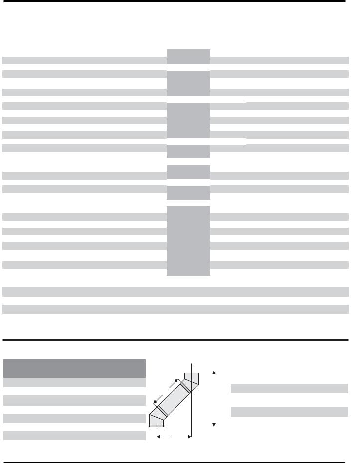
Offset Pipe Selection:
Use this table to determine offset pipe lengths.
Pipe Length |
4” x 6-5/8” Venting |
||
|
|
||
Run (X) |
Rise (Y) |
||
|
|||
|
|
|
|
0”(0mm) |
4-7/8”(124mm) |
13-3/8”(340mm) |
|
|
|
|
|
6”(152mm) |
8”(203mm) |
16-1/2”(419mm) |
|
|
|
|
|
9”(229mm) |
10-1/8”(257mm) |
18-5/8”(473mm) |
|
|
|
|
|
12”(305mm) |
12-1/4”(311mm) |
20-3/4”(527mm) |
|
|
|
|
|
24”(610mm) |
20-5/8”(524mm) |
29-1/8”(740mm) |
|
|
|
|
|
36”(914mm) |
29”(737mm) |
37-1/2”(953mm) |
|
|
|
|
|
48”(1219mm) |
37-7/16”(951mm) |
45-15/16”(1167mm) |
|
|
|
|
|
|
|
|
|
|
|
|
For specific instructions or details on particular |
|
|
|
|
|
|
|
venting components please visit the following |
|
|
|
|
|
|
|
websites: |
|
|
|
|
|
|
|
|
|
|
|
|
|
|
|
|
|
|
|
|
|
|
|
Simpson Direct Vent Pro: www.duravent.com |
L |
|
|
|
|
|
|
Selkirk Direct-Temp: www.selkirkcorp.com |
|
|
|
|
|
|
|
|
|
|
|
|
Y |
|
American Metal Products Amerivent Direct: |
|
|
|
|
|
|
www.americanmetalproducts.com |
||
|
|
|
|
|
|
|
|
|
|
|
|
|
|
|
Metal-Fab Sure Seal: www.mtlfab.com |
|
|
|
|
|
|
|
|
|
|
|
|
|
|
|
Security Secure Vent: www.securitychimneys.com |
|
|
|
|
|
|
|
|
|
|
|
|
|
|
|
|
X
NOTE: Horizontal runs of vent must be level, or have a 1/4 inch rise for every 1 foot of run towards the termination. Never allow the vent to run downward. This could cause high temperatures and may present a possible fire hazard.
Regency® P42-4 Zero Clearance Direct Vent Gas Fireplace |
13 |
INSTALLATION
RIGID PIPE VENTING
Horizontal or Vertical Terminations
The Rigid Pipe Venting System offers a complete line of component parts for installation of both horizontal and vertical installations. Many items are offered in decorative black, as well as galvanized fi nish. We recommend using the galvanized fi nish for installation with the P42.
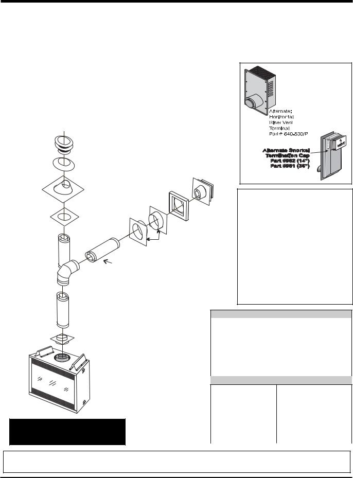
The minimum components required for a basic horizontal termination are:
1Horizontal Termination Cap
190o Elbow
1Flue Adaptor
1Wall Thimble
1Length of pipe to suit wall thickness (see chart)
Vertical
Terminal
Storm Collar
Part # 953
Flashing 943 or 943S
Wall thickness is measured from the back standoffs to the inside mounting surface of termination cap. For siding other than vinyl furring strips may be used, instead of the vinyl siding standoff, to create a level surface to mount the vent terminal. The Terminal must not be recessed into siding. Measure the wall thickness including furring strips.
If a Vinyl Siding Standoff is required (it must be used with vinyl siding), measure to outside surface of wall without siding and add 2 inches.
Vinyl Siding
Standoff (Optional)
Part #950
Ceiling Firestop |
Horizontal |
|
(Part # 963) |
Termination |
|
|
Cap |
|
|
Wall Thimble |
|
Pipe Length |
Part # 942 |
|
Adj.Pipe Length |
||
|
||
|
11" - 14-5/8" |
|
|
90o Elbow |
Alternate |
Horizontal |
Termination Caps |
WARNING: |
Do not combine venting components from different venting systems.
However use of the the AstroCapTM and FPI
Riser is acceptable with all systems.
This product has been evaluated by Intertek for using a Rigid Pipe Adaptor in conjunction with Duravent Direct-Vent GS, Selkirk Direct-Temp, Ameri Vent Direct venting and Security Secure Vent systems. Use of these systems with the
Rigid Pipe adaptor is deemed acceptable and does not affect the Intertek WHI listing of components.
24" Pipe
Length
Rigid Pipe Adaptor
(Part# 510-994)
When using Rigid Vent other than Simpson Dura-Vent, 3 screws must be used to secure rigid pipe to adaptor.
Flat Wall Installation
Wall Thickness |
Vent Length |
|||
|
(inches) |
Required (inches) |
||
4" |
- |
5-1/2" |
6" |
|
7" - 8-1/2" |
9" |
|
||
10" |
- |
11-1/2" |
12" |
|
9" |
- |
14-1/2" |
11" - 14-5/8" Adj. Pipe |
|
15" |
- |
23-1/2" |
17" - 24" Adj. Pipe |
|
Corner Installation
Wall Thickness |
Vent Length |
|||
(inches) |
Required (inches) |
|||
3-1/4" |
- |
6-3/4"11" |
- 14-5/8" Adj. Pipe |
|
7-3/4" - 16-1/4" |
17" - 24" Adj. Pipe |
|||
7-1/4" |
- |
8-3/4" |
6" + 12" |
|
|
|
|
9" + 9" |
|
4-1/4" |
- |
5-3/4" |
6" + 9" |
|
The FPI AstroCapTM and FPI Riser Vent terminal are certifi ed for installations using FPI venting systems as well as Simpson Dura-Vent® Direct Vent GS, American Metal Products Ameri Vent Direct Vent, Security Secure Vent®, Selkirk Direct-Temp. AstroCapTM is a proprietary trademark of FPI Fireplace Products International Ltd. Dura-Vent® and Direct Vent GS are registered and/or proprietary trademarks of Simpson Dura-Vent Co. Inc.
14 |
Regency® P42-4 Zero Clearance Direct Vent Gas Fireplace |
INSTALLATION
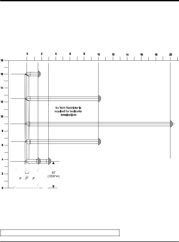
RIGID PIPE VENTING ARRANGEMENTS - HORIZONTAL TERMINATIONS
REGENCY® DIRECT VENT SYSTEM (FLEX) (Propane & Natural Gas)
The shaded areas in the diagram show all allowable combinations of vertical runs with horizontal terminations. The chart below shows the distances with one 90o bend (two 45o elbows equal one 90o elbow). For a second 90o bend, see the "Rigid Pipe Venting Arrangements - Horizontal
Terminations" section.
|
|
|
|
|
|
A vent guard may be required, check local codes. |
|
|
|
|
|
|
|
|
|
|
|
|
|
|
|
|
|
|
|
|
|
|
|
|
|
|
Minimum height |
Note: Must use optional rigid pipe adaptor (Part # 510-994) |
|
|
|
|
|
||
|
|
|
|
|
||
|
|
|
|
|
requirement |
when using rigid pipe venting systems. |
|
|
|
|
|
|
|
|
|
|
|
|
|
Rigid Pipe Systems: |
|
|
|
|
|
|
|
|
|
|
|
|
|
4"(100mm) inner diameter |
|
|
|
|
|
|
6-5/8"(168mm) outer diameter |
|
|
|
|
|
|
|
|
|
|
|
|
|
Regency® Flex: |
|
|
|
|
|
|
|
|
|
|
|
|
|
|
|
|
|
|
|
|
4"(100mm) inner diameter |
|
|
|
|
|
|
6-7/8"(175mm) outer diameter |
•Rigid Pipe Systems: Maintain a 1-1/4"(32mm) clearance to combustibles
•Regency® Flex: Maintain a 1-1/2"(38mm) clearance to combustibles
•Horizontal vent must be supported every 3 feet (0.9 meter)
•Firestops are required at each floor level and whenever passing through a wall
Note: Regency® Direct Vent System (Flex) is only approved for horizontal terminations.
Regency® P42-4 Zero Clearance Direct Vent Gas Fireplace |
15 |
 Loading...