


www.regency-fi re.com
E21 Gas Insert
Owners &
Installation Manual
Tested by
MODELS: E21-NG1 Natural Gas E21-LP1 Propane
Installer: Please complete the details on the back cover and leave this manual with the homeowner.
Homeowner: Please keep these instructions for future reference.
918-354a |
FPI FIREPLACE PRODUCTS INTERNATIONAL LTD. 6988 Venture St., Delta, BC Canada, V4G 1H4 |
10/25/05 |
CONGRATULATIONS!
You are the owner of a state-of-the-art Gas Insert by:
FPI FIREPLACE PRODUCTS INTERNATIONAL LTD.
The Regency Gas Fireplace Series has been designed to provide you with all the warmth and charm of a fi replace, at the fl ick of a switch. The models E21-NG1 and E21-LP1 of this series have been approved by Warnock Hersey for safety. As it also b ars our own mark, it promises to provide you with economy, comfort and security for many trouble free years to follow. Please take a moment now to acquaint yourself with these instructions and the many features of your Regency Fireplace.
2 |
Regency E21 Gas Fireplace Insert |

TABLE OF CONTENTS
E21 GAS INSERT
Page |
Page |
SAFETY LABEL |
|
Safety Labe |
4 |
INSTALLATION INSTRUCTIONS |
|
Before You Start |
5 |
General Safety Information |
5 |
Policy for Factory Built Fireplaces |
6 |
nstallation Checklist |
6 |
Minimum Fireplace Clearances |
6 |
Clearances to Combustibles |
7 |
Gas Connection |
8 |
System Data |
8 |
High Elevation |
8 |
Wiring D agram |
9 |
Flue Connector Installation |
9 |
Offset Flue Adaptor |
10 |
Venting |
10 |
Combustion & Ventilation Air |
10 |
Gas Pressure Test |
10 |
Aeration System |
1 |
Test for Flue Spillage |
1 |
Optional Brick Panel |
1 |
Log Set Installation |
1 |
Faceplate & Trim |
12 |
Flush Glass |
13 |
Flush Louvers |
13 |
Bay Front |
14 |
Bay Louvers |
14 |
Conversion Kit from Natural Gas to Propane |
15 |
Full Screen Front |
17 |
Remote Contro |
19 |
Remote Wall Switch |
19 |
Wall Thermostat |
19 |
Final Check |
20 |
OPERATING INSTRUCTIONS |
|
Operating Instructions |
20 |
Lighting Procedure |
20 |
Shutdown Procedure |
20 |
First Fire |
20 |
Copy of Lighting Plate Instructions |
2 |
Automatic Convection Fan Operation |
22 |
Normal Operating Sounds of Gas Appliances |
22 |
MAINTENANCE |
|
Maintenance Instructions |
22 |
Log Replacement |
22 |
Glass Gasket |
22 |
Gold-Plated Trim |
22 |
Door Glass Replacement |
23 |
Removing and Replacing Valve Assembly |
23 |
Removing and Replacing the Fan |
23 |
PARTS |
|
Parts List |
24 |
WARRANTY |
|
Warranty |
3 |
Regency E21 Gas Fireplace Insert |
3 |
SAFETY LABEL
This is a copy of the label that accompanies |
Note: Regency units are constantly being |
each Regency Gas Insert. We have printed |
improved.Checkthelabelontheunit |
a copy of the contents here for your review. |
and if there is a difference, the label |
The safety label is located on the front inside |
on the unit is the correct one. |
base of the unit visible when the bottom louver |
|
s open |
Please note that with the addition |
|
of thermostat control and outside |
|
combustion air supply, this unit is |
|
approved for bedroom installations. |
276
4 |
Regency E21 Gas Fireplace Insert |
INSTALLATION
IMPORTANT:
SAVE THESE
INSTRUCTIONS
The Regency Gas Fireplace must be installed in accordance with these instructions. Carefully read all the instructions in this manual fi rst. Consult the "authority having jurisdiction" to determine the need for a permit prior to starting the installation. It is the responsibility of the installer to ensure this fi replace is installed in compliancewiththemanufacturer'sinstructions and all applicable codes
BEFORE YOU START
Safe installation and operation of this appliance requires common sense, however, we are required by the Canadian Safety Standards and ANSI Standards to make you aware of the following
INSTALLATION AND REPAIR SHOULD BE DONE BY A QUALIFIED SERVICE PERSON. THE APPLIANCE SHOULD BE INSPECTED BEFORE USE AND AT LEAST ANNUALLY BY A PROFESSIONAL SERVICE PERSON. MORE FREQUENT CLEANING MAY BE REQUIRED DUE TO EXCESSIVE LINT FROM CARPETING,BEDDINGMATERIAL, ETC. IT IS IMPERATIVE THAT CONTROL COMPARTMENTS, BURNERS AND CIRCULATING AIR PASSAGEWAYS OF THE APPLIANCE BE KEPT CLEAN.
DUE TO HIGH TEMPERATURES, THE APPLIANCE SHOULD BE LOCATED OUT OF TRAFFIC AND AWAY FROM FURNITURE AND DRAPERIES.
WARNING: FAILURE TO INSTALL THIS APPLIANCE CORRECTLY WILLVOIDYOURWARRANTYAND MAY CAUSE A SERIOUS HOUSE
FIRE.
CHILDRENANDADULTSSHOULD BEALERTEDTOTHEHAZARDSOF HIGHSURFACETEMPERATURES, ESPECIALLY THE FIREPLACE GLASS,ANDSHOULDSTAYAWAY TO AVOID BURNS OR CLOTHING IGNITION.
YOUNG CHILDREN SHOULD BE CAREFULLY SUPERVISEDWHEN THEY ARE IN THE SAME ROOM AS THE APPLIANCE.
CLOTHING OR OTHER FLAMMABLEMATERIALSHOULD NOT BE PLACED ON OR NEAR THE APPLIANCE.
GENERAL SAFETY INFORMATION
1)The appliance installation must conform with local codes or, in the absence of local codes,withthecurrentCanadianorNational Gas Codes, CAN1-B149 or ANSI Z223.1 nstallation Codes.
2)The appliance when installed, must be electrically grounded in accordance with localcodes,orintheabsenceoflocalcodes with the current National Electrical Code, ANSI/NFPA 70 or CSA C22.1 Canadian Electrical Code.
3)See general construction and assembly nstructions.Theapplianceandventshould
be enclosed
4)This appliance must be connected to the specifi ed vent and termination cap to the outside of the building envelope. Never vent to another room or inside a building. Make sure that the vent is installed as per Venting instructions
5)This appliance may only be installed in a vented, solid fuel burning masonry, listed factory built fi replace, or zero clearance kit part # 530-936.
6)This appliance is Listed for bedroom installationswhenusedwithaListedMillivolt
Thermostat. Some areas may have further requirements, check local codes before installation
7)This appliance is Listed for Alcove installations, maintain minimum Alcove clearances as follows, minimum ceiling height of 53-1/2", minimum width of 48" and a maximum depth of 36"
8)This unit is not approved for installation into a mobile home
9)Inspect the venting system annually for blockage and any signs of deterioration.
10)Any safety glass removed for servicing must be replaced prior to operating the appliance
11)To prevent injury, do not allow anyone who is unfamiliar with the operation to use the fi replace nsert
12)Wearglovesandsafetyglassesforprotection while doing required maintenance
13)Ensureadequatecombustionandventilation air
14)Under no circumstances should this appliance be modifi ed. Parts that have to beremovedforservicingshouldbereplaced prior to operating this appliance
15)Installationandanyrepairstothisappliance shouldbedonebyaqualifi edserviceperson. A professional service person should be called to inspect this appliance annually.
Make it a practice to have all of your gas appliances checked annually
16)Do not slam shut or strike the glass door
17)Under no circumstances should any solid fuels (wood, paper, cardboard, coal, etc.) be used in this appliance
18)The appliance area must be kept clear and free of combustible materials, (gases and other fl ammable vapours and liquids).
19)Donotusethisapplianceifanyparthasbeen under water. Immediately call a qualifi ed service technician to inspect the appliance and to replace any part of the electrical control system and any gas control which has been under water
20)WARNING: Failure to position the parts in accordance with the diagrams in this manual or failure to useonlypartsspecifi callyapproved with this appliance may result in property damage or personal injury.
21)WARNING: Operation of this appliance when not connected to a properly installed and maintained venting system or tampering with the blocked vent shut-off system can result in carbon monoxide (CO) poisoning and possible death.
Regency E21 Gas Fireplace Insert |
5 |
INSTALLATION
POLICY FOR SOLID FUEL BURNING & FACTORY BUILT FIREPLACES
The Regency E21 may be installed and vented intoanysolidfuelfi replacethathasbeeninstalled n accordance with the National, Provincial and local building codes and is constructed of noncombustible materials.
1)Installer must mechanically attach the supplied label to the inside of the fi rebox of the fi replace into which the gas fi replace insert is installed
WARNING Thisfi replacehasbeenconverted for use with a gas fi replace insert only and cannot be used for burning wood or solid fuels unless all original parts have been replaced, and the fi replace re-approved by the authority having jurisdiction."
2)Do not cut any sheet-metal parts of the
fireplace, in which the gas fi replace insert is to be installed
3)Ifthefactory-builtfi replacehasnogasaccess hole(s) provided, an access hole of 1-1/2" (37.5mm) or less may be drilled though the lowersidesorbottomofthefi reboxinaproper workmanship like manner.This access hole must be plugged with a non-combustible insulation after the gas supply line has been installed
4)Thefi replacefl uedampercanbefullyblocked open or removed for installation of the gas
fireplace insert.
5)The fi replace and fi replace chimney must be clean and in good working order and constructed of non-combustible materials.
6)The chimney cleanouts must fi t properly
7)Refractory (fi rebricks), glass doors, screen rails, screen mesh and log grates can be removed from the fi replace before installing the gas fi replace insert
8)Smoke shelves, shields and baffl es may be removedifattachedbymechanicalfasteners. f any part is removed it must not weaken the structural integrity of the factory built
9)Trim panels or surrounds shall not seal ventilation openings in the fi replace
INSTALLATION
CHECKLIST
1)Locate appliance, check Clearances to Combustibles, page 7
2)Make gas and electrical connections, page
8.Test the pilot. Must be as per diagram, page 11
3)nstall Flue Connector, page 9
4)nstall vent, page 10
5)Test Gas pressure, page 10, and check aeration, page 11
6)Test for fl ue spillage, page 11
7)Install brick panels (optional), page 11
8)Install log set, page 11
9)Install Faceplate and Trim, page 12
10)Install Flush Door Front (Standard), page 13
11)Install Optional Bay Front and optional Bay Gold Trim, page 14
12)InstallLouvers(FlushorBay),pages13and 14
13)InstalloptionalWallSwitch,RemoteControl, or Wall Thermostat, page 19
14)Final check, page 20
Before leaving this unit with the customer, the installer must ensure that the appliance is
fi ring correctly and operation fully explained to customer
This includes
1)Clockingtheappliancetoensurethecorrect fi ring rate (rate noted on label) after burning appliance for 15 minutes.
2)Ifrequired,adjustingtheprimaryairtoensure that the fl ame does not carbon. First allow the unit to burn for 15-20 min. to stabilize
3)Ensure that the appliance is venting correctly
CAUTION: Anyalterationtotheproductthat causes sooting or carboning that results in damage is not the responsibility of the manufacturer.
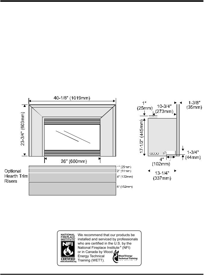
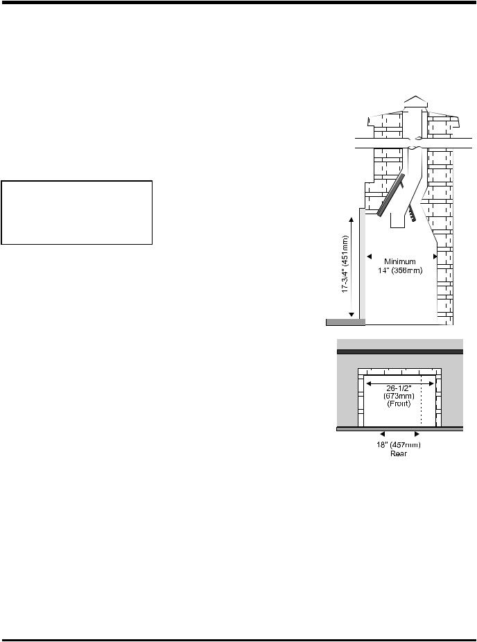
MINIMUM FIREPLACE
CLEARANCES
Diagram shows the minimum fi replace opening required to be able to install the Regency gas
fi replace insert
Note:IfyouareinstallingtheMoldedFaceplate, the minimum fireplace dimensions are as follows
Width (at front): |
29-1/8" (740mm) |
Depth |
15" (381mm) |
Height |
18-5/8" (473mm) |
6 |
Regency E21 Gas Fireplace Insert |
INSTALLATION
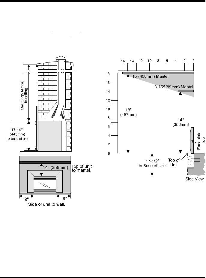
CLEARANCES TO
COMBUSTIBLES
The minimum clearance from the side of the appliance to a combustible |
Note: Anon-combustible mantel may be installed at a lower height |
side wall is 9 inches (229mm). The minimum clearance from the top of |
if the framing is made of metal studs covered with a non- |
the louver to a combustible mantel is 14 inches (356mm) The minimum |
combustible board. |
height from the top of the louver to the ceiling is 36 inches (914mm) |
|
See diagram. |
|
Regency E21 Gas Fireplace Insert |
7 |
INSTALLATION
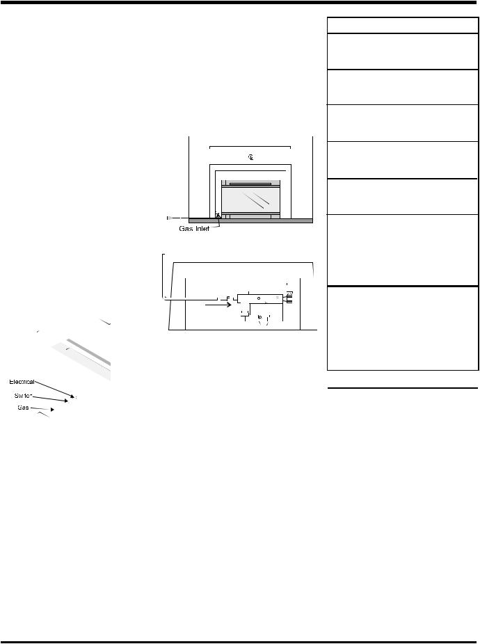
GAS CONNECTION
Only persons licensed to work with gas piping may make the necessary gas connections to this appliance.
Thegasconnectionisa3/8"NPTaccessibleon the left side of the unit. The gas line connection may be made of rigid pipe, copper pipe or an approved fl ex connector. (If you are using rigid pipe, ensure that the valve can be removed for servicing.) Since some municipalities have additionallocalcodesitisalwaysbesttoconsult with your local authorities and the CAN/CGA B149 installation code
For USA installations follow local codes and/or the current National Fuel Gas Code, ANSI Z223.1
When using copper or fl ex connectors use only approvedfi ttings.Alwaysprovideaunionsothat gas lines can be easily disconnected for burner or fan servicing. Flare nuts for copper lines and fl ex connectors are usually considered to meet this requirement
Important: Always check for gas leaks with a soap and water solution or gas leak detector. Do not use open fl ame for leak testing.
For minimum and maximum supply pressure see the System Data table.
1)If the appliance is to be installed into an existing chimney system, thoroughly clean themasonryfi replacethathasbeenchosen for the Regency Gas Fireplace
2)Theapplianceisprovidedwithanopeningon thelefthandsideofthecontrolcompartment for the gas line.
Note: During any pressure testing of the gas supplypipingsystemthatexceedstestpressures of 1/2 psig, this appliance and its individual shut-off valve must be disconnected from the piping system. If test pressures equal to or less than 1/2 psig are used then this appliance must be isolated from the piping system by closing its individual manual shut-off valve during the testing
CAUTION: If the glass is removed for servicing, it must be replaced prior to operating the appliance. The glass must be fixed in the closed position when operating.
System Data
For altitude: |
Natural Gas |
0-2000 ft. |
|
|
Propane: |
0-4500 ft. |
|
Burner Inlet Orifi ce Sizes: |
|
||
|
Natural Gas |
Propane |
|
Burner |
|
#43 |
#54 |
Max. Input Rating |
|
|
|
- Natural Gas |
23,500 Btu/h |
||
- Propane |
|
22,500 Btu/h |
|
Min. Input Rating |
|
|
|
Natural Gas +/-5% |
11,750 Btu/h |
||
-Propane |
+/-5% |
11,250 Btu/h |
|
Supply Pressure |
|
|
|
Natural Gas |
|
min. |
5.0" w.c |
Propane |
|
min. |
12.0" w.c. |
Manifold Pressure (High) |
|
||
Natural Gas |
|
3.8" |
+/- 0.2" w.c |
Propane |
|
11" |
+/- 0.2" w.c |
Circulation Fan: 120 VAC, 60 Hz |
|||
Variable Speed: 127 CFM, thermally |
|||
activated |
|
|
|
NATURAL GAS E21-NG1 |
|||
For altitude: |
2000 ft - 4500 ft. |
||
Burner Inlet Orifi ce Size: |
44 DMS |
||
Max. Input Rating |
22,000 Btu/h |
||
Min. Input Rating |
+/-5% |
11,000 Btu/h |
|
HIGH ELEVATION
This unit is approved in Canada for altitude 0 to 4500 ft. (CAN/CGA 2.17-M91) with the orifi ce supplied.
8 |
Regency E21 Gas Fireplace Insert |
INSTALLATION
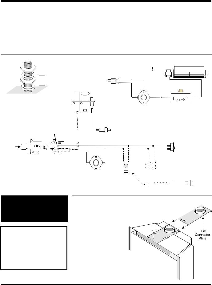
WIRING DIAGRAM FOR THE E21-NG1 AND E21-LP1
Thisheaterdoesnotrequirea120VA.C.supply for operation. In case of a power failure, the burner switch and the optional remote control/ thermostat will continue to operate. However, a 120V A.C. power supply is needed for the fan/blower operation.
Caution: Ensure that the wires do not touch any hot surfaces and are away from sharp edges.
When connected with 120 volts, the appliance must be electrically grounded in accordance with local codes or, in the absence of local
codes the current CSA C22.1 (in Canada) or with the National Electrical Code ANSI/NFPA 70-1987 (in USA).
NOTE: This unit is equipped with a heat sensor thermodisc which will prevent the blower from operating until the unit reaches the correct temperature.
CAUTION: Label all wires prior to disconnection when servicing controls. Wiring errors can cause improper and dangerous operation.
WARNING: Electrical Grounding
Instructions
This appliance is equipped with a three pronged (grounding) plug for yourprotectionagainstshockhazard and should be plugged directly into a properly grounded three-prong receptacle. Do not cut or remove the grounding prong from this plug.
FLUE CONNECTOR INSTALLATION
1)Removethescrewholdingthefl ueconnector plate to the appliance
2) Slide the plate out and attach to the fl ue liner inside the fi replace to the fl ue collar with three sheet metal screws
3) Place the appliance on the hearth.
Push the appliance into the fi replaceandatthesametimeslidethe plate back onto the appliance
4)Replace the screw holding the plate just before completely pushing the appliance into the fi replace
Note: Do not operate unit if fl ue connector is not fastened in original position.
Regency E21 Gas Fireplace Insert |
9 |
INSTALLATION
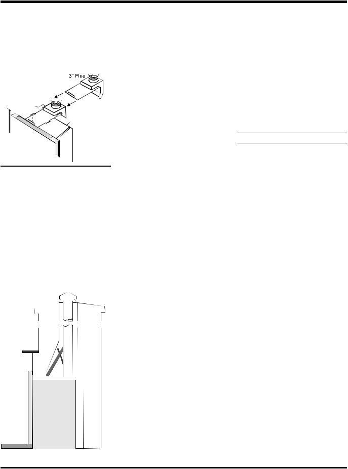
OFFSET FLUE
ADAPTOR
A Offset Flue Adaptor Kit, Part #532-920 is available as an accessory to move the fl ue outlet back for easier liner installations in deep fi replaces
VENTING
THE APPLIANCE MUST NOT BE CONNECTED TO A CHIMNEY FLUE SERVING A SEPARATE SOLID FUEL BURNING APPLIANCE.
This appliance is designed to attach to a 4" diameter type B-Vent or double thickness approved aluminium fl ex liner
The fl ue collar of the appliance will fi t inside a standard vent and may be fastened directly to the vent by sheet metal screw or a B-Vent, single wall vent connector
B-Vent chimneys require a 1" clearance to combustibles
A3"diametertypeB-Ventorapprovedaluminium fl ex liner may also be used with a 4" to 3" reducing adapter. Consult venting charts and local code requirements
TheRegencyInsertincorporatesitsowninternal draft hood, so no additional external draft hood is required. Check periodically that the vent is unrestricted and an adequate draft is present when the unit is in operation
Beforeinstallingtheventsystemensurethatthe damper plate is locked into the open position and secure to prevent the damper plate from falling down and crushing the liner
The appliance is equipped with a vent safety shutoff system and a safety control system designed to protect against improper venting of combustion products. The appliance will not function without being connected to a proper system
WARNING:Operationofthisheater when not connected to a properly installed and maintained venting system or tampering with the vent shut-offsystemcanresultincarbon monoxide (CO) poisoning and possible death.
This appliance must not be connected to a chimney fl ue serving a separate solid fuel burning appliance
For best venting performance, we recommend the following venting rules:
1)Use only certifi ed Type B gas vent or approved fl ex liner
2)Follow the vent manufacturer's instructions and clearance requirements
3)Observe any local code restrictions, if any, regarding the installation of gas inserts.
4)Use as few elbows as possible.
5)Keephorizontallengthsasshortaspossible and maintain at least an upward slope of 1/4 in. (6.4mm) for every 12 in. (305mm) of horizontal run
6)Terminate the vent with a suitable certifi ed vent cap
COMBUSTION AND VENTILATION AIR
WARNING: This appliance needs fresh air for safe operation and must be installed with provisions for adequate combustion and ventilation air available to the room in which it is to be operating.
Follow CAN/CGA B149 (in Canada) or ANSI Z223.1 (in the USA) requirements, and any local codes or regulations of the enforcing authority
Air for combustion is drawn in through the front of the unit, therefore, the front of the unit must be kept clear of any obstructions
GAS PIPE
PRESSURE TESTING
The appliance must be isolated from the gas supply piping system by closing its individual manual shut-off valve during any pressure testing of the gas supply piping system at test pressures equal to or less than 1/2 psig. (3.45 kPa). Disconnectpipingfromvalveatpressures over 1/2 psig
Themanifoldpressureiscontrolledbyaregulator builtintothegascontrol,andshouldbechecked at the pressure test point
Note: Toproperlycheckgaspressure,both inlet and manifold pressures should be checked using the valve pressure ports on the valve.
1)Make sure the valve is in the "OFF" position
2)Loosen the "IN" and/or "OUT" pressure tap(s), turning counterclockwise with a 1/8" wide fl at screwdriver.
3)Attach manometer to "IN" and/or "OUT" pressure tap(s) using a 5/16" ID hose.
4)Light the pilot and turn the valve to "ON" position. Read manometer
5)The pressure check should be carried out with the unit burning and the setting should be within the limits specifi ed on the safety label
6)When fi nished reading manometer, turn off the gas valve, disconnect the hose and tighten the screw (clockwise) with a 1/8"
fl at screwdriver. Note: Screw should be snug, but do not over tighten
10 |
Regency E21 Gas Fireplace Insert |
 Loading...