


H3-HD101
INSTALLATION & OPERATING
®
INSTRUCTIONS
Models HD101–HD401
Types H & WH
WARNING: If these instructions are not followed exactly, a fire or explosion may
result causing property damage, personal injury or death
FOR YOUR SAFETY: Do not store or use gasoline or other flammable vapors and
liquids or other combustible materials in the vicinity of this or any other appliance. To
do so may result in an explosion or fire.
WHAT TO DO IF YOU SMELL GAS:
• Do not try to light any appliance.
• Do not touch any electrical switch; do not use any phone in your building.
• Immediately call your gas supplier from a neighbor's phone. Follow the gas
supplier's instructions.
• If you cannot reach your gas supplier, call the fire department.
Installation and service must be performed by a qualified installer, service agency or
the gas supplier.
.
This manual should be maintained in legible condition and kept adjacent to the heater or in another safe place for
future reference.
CATALOG NO. 1000.52D Effective: 10-15-15 Replaces: 09-14-12 P/N 241356 Rev. 5

Rev. 5 reflects the following:
Changes to: Table C on page 9, Figs. 7 and 8 on page 10, “Direct Combustion Air” on page 11, “Recovery
Water Connections” on page 13, Figs. 10-12 on page 15, “Piping-Heating Boilers” on page 16, Table G on
page 18, Table I on page 22, Table K on page 25, Table L on page 27, Table M on page 29, Table N on page
30, Fig. 27 on page 34, Table P on page 43, Figs 37-38 on page 45, Fig. 39 on page 46.
Additions: “System Design” on page 14, Wiring Diagrams on pages 36-39, Table Q on page 43
Deletions: None
2

CONTENTS
WARNINGS 4
Pay Attention to These Terms 4
BEFORE INSTALLATION 5
Product Receipt 5
Model Identification 5
Ratings and Certifications 5
Installations at Elevation 5
Component Locations 6
General Information 7
GENERAL SAFETY 8
Time/Temperature Relationships in Scalds 8
INSTALLATION 9
Installation Codes 9
Equipment Base 9
Clearances 9
Combustion and Ventilation Air 11
Conventional Combustion
Air Supply 11
Water Piping 12
Hydronic Heating 14
Domestic Hot Water Piping 16
Gas Supply 17
Electrical Power Connections 18
Venting 21
Outdoor Installation 31
CONTROLS 32
Ignition Control Module 32
Outdoor Air Reset Temperature Controller
(Standard for HD101-HD301 Type H) 32
Digital Temperature Control (Optional) 34
High Limit (Manual Reset) 34
High Limit — Auto Reset (Optional) 34
Flow Switch 35
High and Low Gas Pressure Switches
(Optional) 35
Low Water Cut Off (Optional) 35
WIRING DIAGRAM—MODELS
HD101–HD151 TYPE WH 36
WIRING DIAGRAM—MODELS
HD101-HD151 TYPE H 37
WIRING DIAGRAM—MODELS HD201HD401 TYPE WH 38
WIRING DIAGRAM—MODELS
HD201-HD401 TYPE H 39
HD TROUBLESHOOTING 40
PRE-START-UP 41
Filling System-Heating Heaters 41
Domestic Hot Water Heaters 41
Inspect Venting System 41
Pre-Start-Up Check 41
INITIAL START-UP 41
Tools Needed 41
Preparation for Start-Up 41
Start-Up 42
Main Burner Adjustment 43
Gas Valve Adjustment 43
Gas Type Conversion on Valve 44
Safety Inspection 44
Follow-Up 44
POST START-UP CHECK 45
Air Filter Inspection/Removal 46
Heat Exchanger Removal 46
MAINTENANCE 47
Suggested Minimum Maintenance
Schedule 47
APPENDIX 48
Inside Combustion Air Contamination 48
Important Instructions for the
Commonwealth of Massachusetts 49
3
WARNINGS — Pay Attention to These Terms
DANGER:
WARNING:
CAUTION:
NOTE:
DANGER: Make sure the gas on which the heater
will operate is the same type as that specified on the
heater rating plate.
WARNING: Should overheating occur or the gas
supply valve fail to shut, do not turn off or disconnect
the electrical supply to the heater. Instead, shut off
the gas supply at a location external to the heater.
WARNING: Risk of electrical shock. More than one
disconnect switch may be required to deenergize the
equipment before servicing.
WARNING - CALIFORNIA PROPOSITION
65: This product contains chemicals known to the
State of California to cause cancer, birth defects or
other reproductive harm.
WARNING: This unit contains refractory ceramic
fiber (RCF) insulation in the combustion chamber.
RCF, as manufactured, does not contain respirable
crystalline silica. However, following sustained
exposure to very high temperatures (>2192F), the
RCF can transform into crystalline silica
(cristabolite). The International Agency for Research
on Cancer (IARC) has classified the inhalation of
crystalline silica (cristabolite) as carcinogenic to
humans.
When removing the burners or heat exchangers,
take precautions to avoid creating airborne dust and
avoid inhaling airborne fibers. When cleaning spills,
use wet sweeping or High Efficiency Particulate Air
(HEPA) filtered vacuum to minimize airborne dust.
Use feasible engineering controls such as local
exhaust ventilation or dust collecting systems to
minimize airborne dust. Wear appropriate personal
protective equipment including gloves, safety
glasses with side shields, and appropriate NIOSH
certified respiratory protection, to avoid inhalation of
airborne dust and airborne fiber particles.
Indicates the presence of immediate hazards which will cause severe
personal injury, death or substantial property damage if ignored.
Indicates the presence of hazards or unsafe practices which could cause
severe personal injury, death or substantial property damage if ignored.
Indicates the presence of hazards or unsafe practices which could cause
minor personal injury or product or property damage if ignored.
Indicates special instructions on installation, operation, or maintenance which
are important but not related to personal injury hazards.
WARNING: To minimize the possibility of improper
operation, serious personal injury, fire, or damage to
the heater:
• Always keep the area around the heater free of
combustible materials, gasoline, and other
flammable liquids and vapors.
• Heater should never be covered or have any
blockage to the flow of fresh air to the heater.
WARNING: Do not use this heater if any part has
been under water. Immediately call a qualified
service technician to inspect the heater and to
replace any part of the control system and any gas
control which has been under water.
CAUTION: Operation of this heater in lowtemperature systems requires special piping.
Harmful internal condensation will occur if the inlet
water temperature does not exceed 105°F. Warranty
claims will be denied when condensation occurs.
CAUTION: If this heater is to be installed above
radiation level, it must be provided with a low water
cut-off device at the time of heater installation.
CAUTION: If this heater is to be installed in a
negative or positive pressure equipment room, there
are special installation requirements. Consult factory
for details.
CAUTION: This heater requires forced water
circulation when the burner is operating. See
minimum and maximum flow rates. Severe damage
will occur if the heater is operated without proper
water flow circulation.
4

BEFORE INSTALLATION
Model Identification
Raypak strongly recommends that this manual be reviewed thoroughly before installing your Hi Delta
heater. Please review the General Safety information
before installing the heater. Factory warranty does not
pply to heaters that have been improperly installed or
a
operated (refer to the warranty at the back of this manual). Installation and service must be performed by a
qualified installer, service agency or the gas supplier.
If, after reviewing this manual, you still have questions
which this manual does not answer, please contact
your local Raypak representative or visit our website at
www.raypak.com.
Thank you for purchasing a Raypak product. We hope
you will be satisfied with the high quality and durability
of our equipment.
Product Receipt
WARNING: Pump motors should NOT be
supported by any type of stand or support from
above due to possible misalignment of pump and
motor which may occur.
On receipt of your heater it is suggested that you visually check for external damage to the shipping crate. If
the crate is damaged, make a note to that effect on the
Bill of Lading when signing for the shipment. Next,
remove the heater from the shipping packaging.
Report any damage to the carrier immediately.
On occasion, items are shipped loose. Be sure that
you receive the correct number of packages as indicated on the Bill of Lading.
Claims for shortages and damages must be filed with
the carrier by consignee. Permission to return goods
must be received from the factory prior to shipping.
Goods returned to the factory without an authorized
Returned Goods Receipt number will not be accepted.
All returned goods are subject to a restocking charge.
The model identification number and heater serial
number are found on the heater data plate located on
he right side jacket of the heater. The model number
t
will have the form H3-HD101 or similar depending on
the heater size and configuration. The first character of
the model number identifies application (H = Hydronic
Heating System, WH = Hot Water Supply System).
The second character identifies the firing mode (3 two stage firing, 4 - On/Off firing ). The next three
places identify the size of the heater.
Ratings and Certifications
Standards:
• Gas-Fired Low Pressure Steam and Hot Water
Heaters, ANSI Z21-13 • CSA 4.9 - latest edition
• Industrial and Commercial Gas-Fired Package
Heaters, CAN 3.1 - latest edition
• Gas Water Heaters, ANSI Z21.10.3 • CSA 4.3 - latest edition
All Raypak heaters are National Board Approved, and
design-certified and tested by the Canadian Standards
Association (CSA) for the U.S. and Canada. Each
heater is constructed in accordance with Section IV of
the American Society of Mechanical Engineers
(ASME) Heater Pressure Vessel Code and bears the
ASME stamp. The heater also complies with the latest
edition of ASHRAE 90.1 Standard.
WARNING: Altering any Raypak pressure vessel
by installing replacement heat exchangers, tube
bundle headers, or any ASME parts not
manufactured and/or approved by Raypak will
instantly void the ASME and CSA ratings of the
vessel and any Raypak warranty on the vessel.
Altering the ASME or CSA ratings of the vessel also
violates national, state, and local approval codes.
Installations at Elevation
When ordering parts, you must specify the model and
serial number of the heater. When ordering under warranty conditions, you must also specify the date of
installation.
Purchased parts are subject to replacement only
under the manufacturer’s warranty. Debits for defective replacement parts will not be accepted. Parts will
be replaced in kind only per Raypak’s standard warranties.
Rated inputs are suitable for up to 2000 feet elevation
without de-rate. Consult the Factory for installations at
any altitude in excess of 2000 feet.
5
(BEHIND CONTROLLER)
CONTROLLER
(OPTIONAL ON HD401)
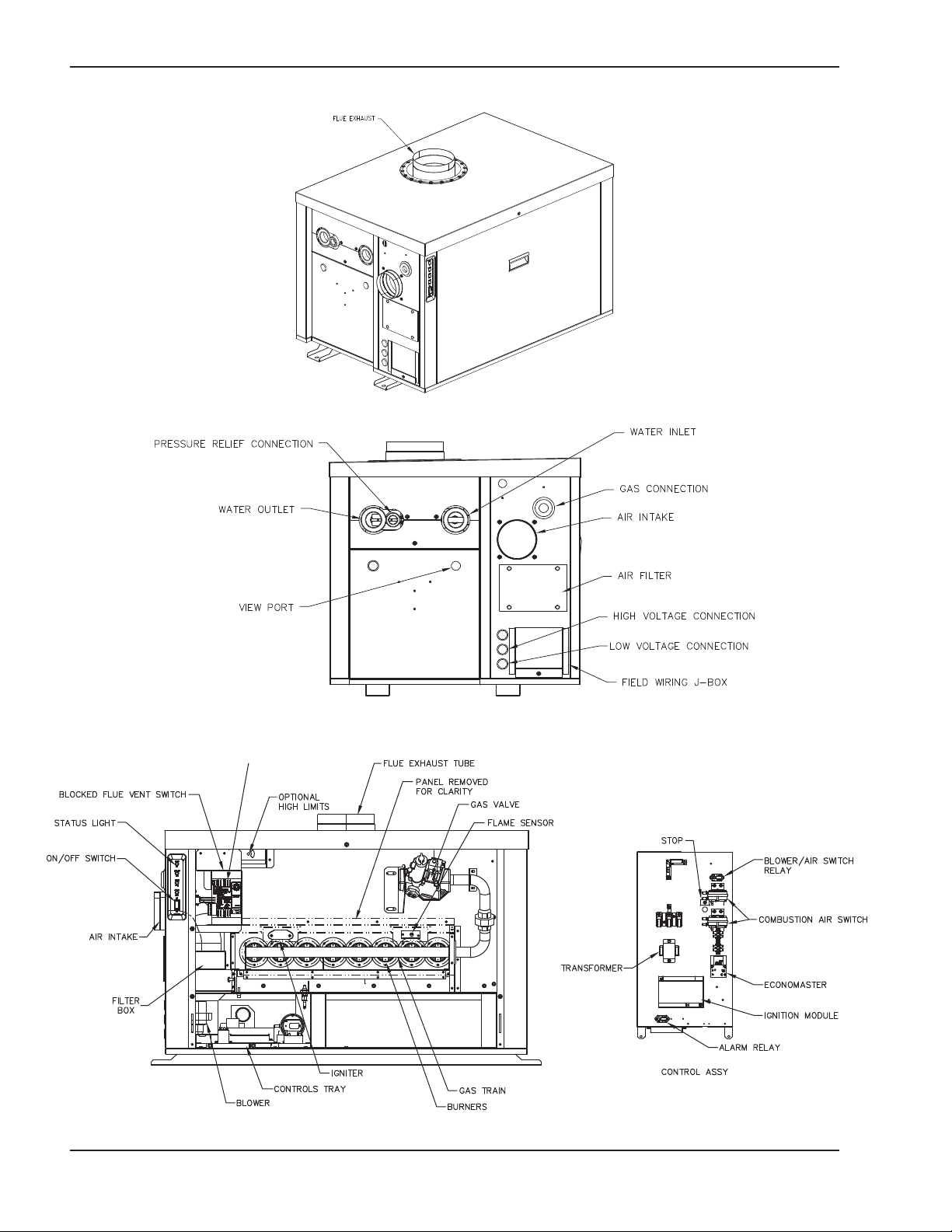
Component Locations
Fig. 1: Component Locations — Angle View
Fig. 3: Component Locations — Front (Panels removed for clarity)
Fig. 2: Component Locations — Left Side
6
General Information
Model
No.
HD101 2 4
HD151 3 4
HD201 4 5
HD251 5 5
HD301 6 5
HD401 8 6
uantity of Burners
Q
Table A: Basic Data
Vent Size (in.)
Flue Intake
4
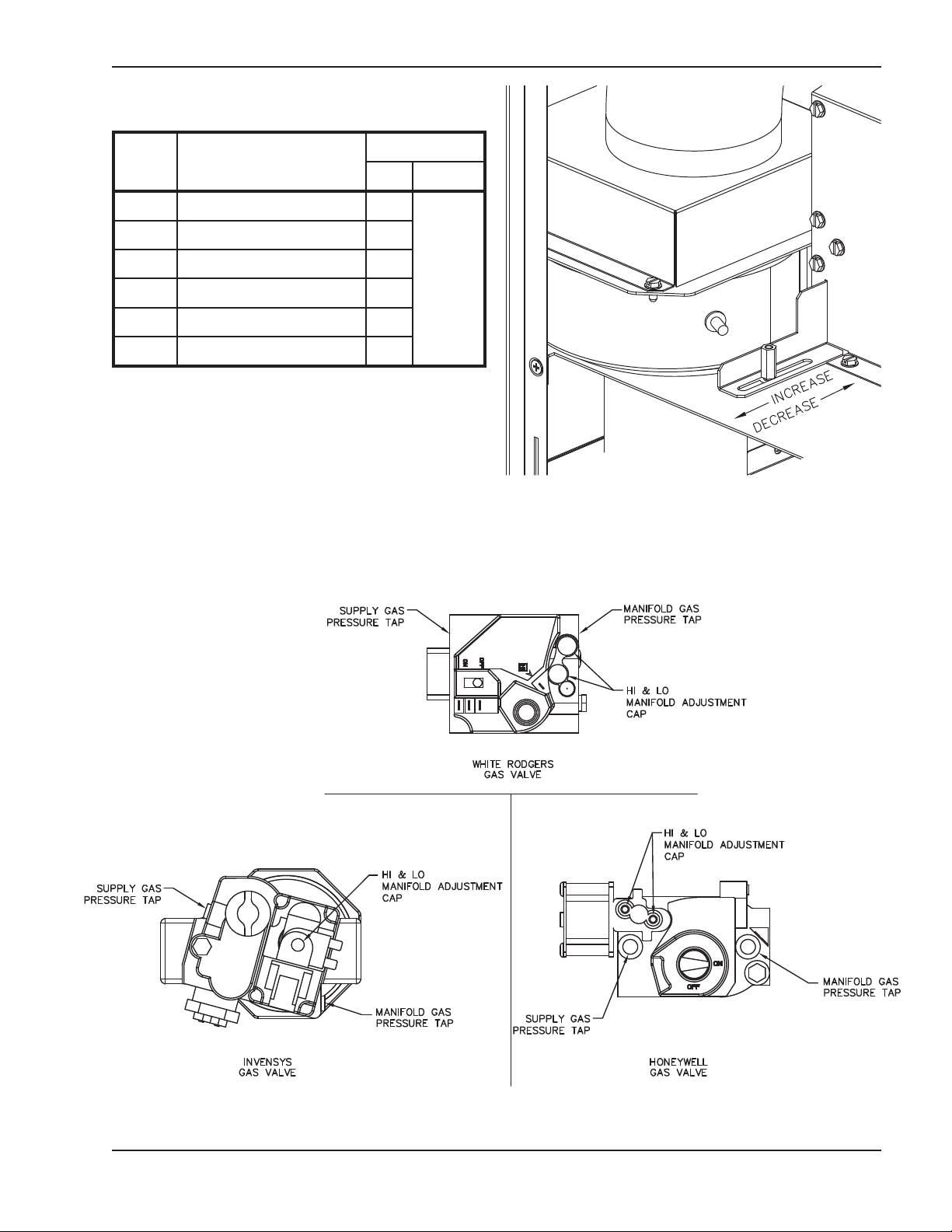
Fig. 4: Air Shutter Adjustment
Fig. 5: Gas Valves
7
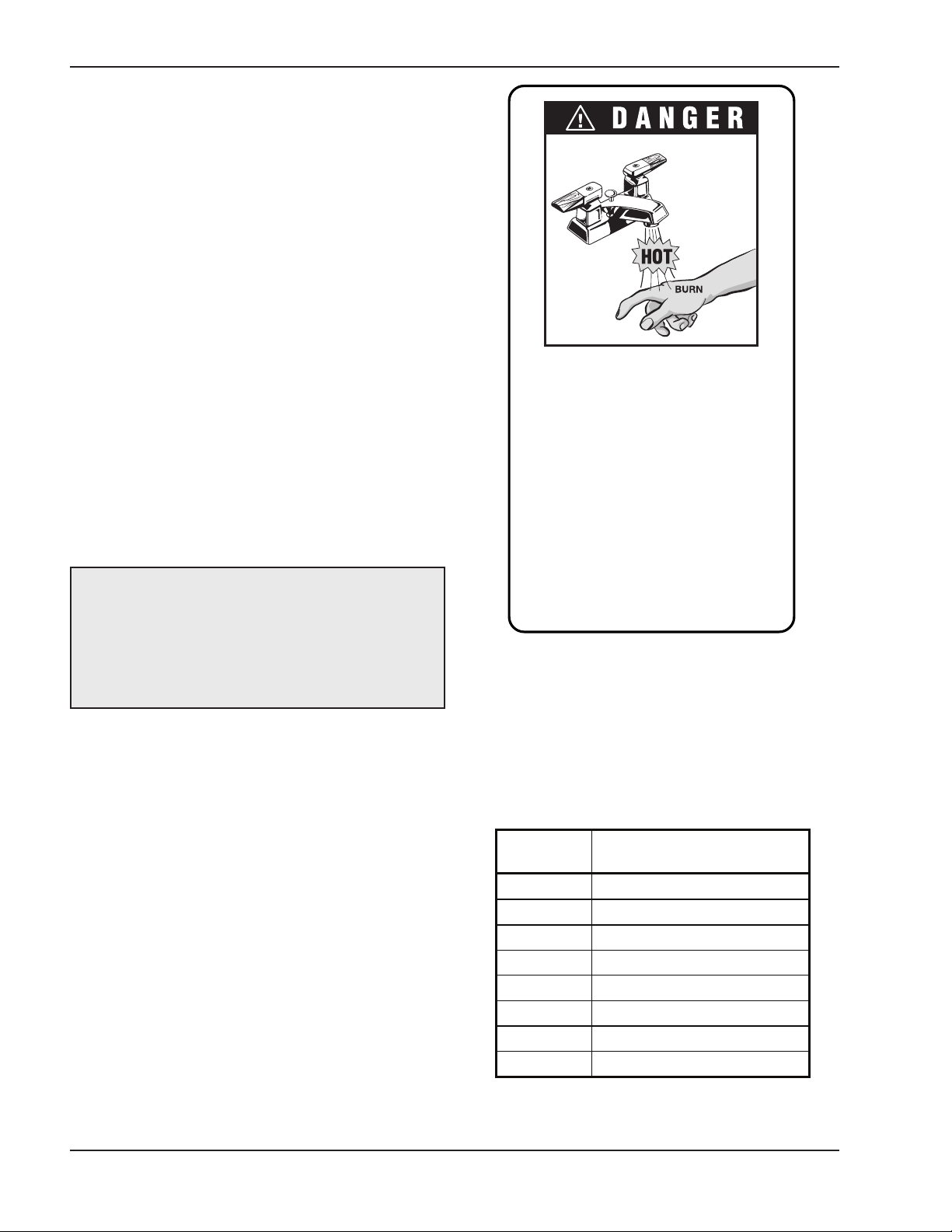
GENERAL SAFETY
Water temperature over 125°F can
c au se in s t an t s ev e r e b ur n s or de a t h
from scalds.
Children, disabled, and elderly are
at highest risk of being scalded.
See instruction manual before setting temperature at water heater.
Feel water before bathing or showering.
Temperature limiting valves are
available, see manual.
Water
Temp.
Time to Produce Serious
Burn
120°F More than 5 minutes
125°F 1-1/2 to 2 minutes
130°F About 30 seconds
135°F About 10 seconds
140°F Less than 5 seconds
145°F Less than 3 seconds
150°F About 1-1/2 seconds
155°F About 1 second
Table courtesy of The Shriners Burn Institute
To meet commercial hot water use needs, the high
limit safety control on this water heater will shut off the
main gas valve before the outlet temperature reaches
210°F. However, water temperatures over 125°F can
cause instant severe burns or death from scalds.
When supplying general purpose hot water, the recommended initial setting for the temperature control is
125°F.
Safety and energy conservation are factors to be considered when setting the water temperature on the
thermostat. The most energy-efficient operation will
result when the temperature setting is the lowest that
satisfies the needs of the application.
Water temperature over 125°F can cause instant
severe burns or death from scalds. Children, disabled
and elderly are at highest risk of being scalded.
• Feel water before bathing or showering.
• Temperature limiting valves are available.
NOTE: When this water heater is supplying general
purpose hot water for use by individuals, a
thermostatically controlled mixing valve for reducing
point of use water temperature is recommended to
reduce the risk of scald injury. Contact a licensed
plumber or the local plumbing authority for further
information.
Maximum water temperatures occur just after the
heater’s burner has shut off. To determine the water
temperature being delivered, turn on a hot water
faucet and place a thermometer in the hot water
stream and read the thermometer.
Time/Temperature
Relationships in Scalds
The following chart details the relationship of water
temperature and time with regard to scald injury and
may be used as a guide in determining the safest
water temperature for your applications.
Table B: Time to Produce Serious Burn
8
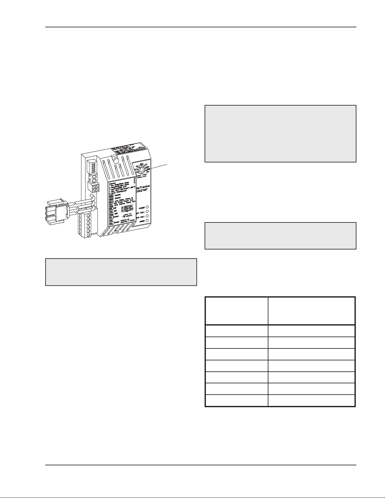
Raypak offers several optional temperature controllers
ADJUSTMENT
WHEEL
for regulation of the water temperature in the heater.
Type H models 101 through 301 are equipped as standard with an onboard operating controller to provide
reset of the water temperature based on outdoor air
temperature. To comply with safety regulations, the
temperature controller will be set at the lowest setting
when shipped from the factory.
Equipment Base
The heater should be mounted on a level, structurally
ound surface. The heater is approved for installation
s
on a combustible surface but must NEVER be
installed on carpeting. Gas-fueled equipment installed
in enclosed parking garages must be located at least
8 in. above the floor.
1
To adjust the water temperature, insert a small straight
screwdriver into the adjustment wheel on the front of
temperature control and turn the wheel to the desired
setting (See Fig. 6).
Fig. 6: Temperature Controller
CAUTION: Hotter water increases the risk of scalding! There is a hot water scald potential if the
thermostat is set too high.
CAUTION: The heater should be located in an area
where water leakage will not result in damage to the
area adjacent to the appliance or to the structure.
When such locations cannot be avoided, it is
recommended that a suitable catch pan, adequately
drained, be installed under the appliance. The pan
must not restrict air flow.
In addition, the heater shall be installed such that the
gas ignition system components are protected from
water (dripping, spraying, rain, etc.) during appliance
operation or service (circulator replacement, control
replacement, etc.).
WARNING: This product must be installed by a
licensed plumber or gas fitter when installed within
the Commonweatlh of Massachusetts.
Clearances
Indoor/Closet Installations
INSTALLATION
Installation Codes
Installations must follow these codes:
· Local, state, provincial, and national codes, laws,
regulations and ordinances.
· National Fuel Gas Code, ANSI Z223.1- latest edition (NFGC).
· National Electrical Code, ANSI/NFPA 70 - latest
edition (NEC).
· Standard for Controls and Safety Devices for
Automatically Fired Heaters, ANSI/ASME CSD-1,
when required (CSD-1).
· For Canada only: CAN/CGA B149 Installation
Code (B149) and C.S.A. C22. 1 C.E.C. Part 1
(C22. 1).
Heater Side
Front 24”
Rear 2”
Floor* 0”
Top 24”
Left** 12”
Right** 6”
Water Side 24”
*DO NOT install on carpeting.
**When water connections are on other side.
Table C: Combustible Clearances — Indoor/Closet
Installations
9
Minimum Installed
Combustible Clearance
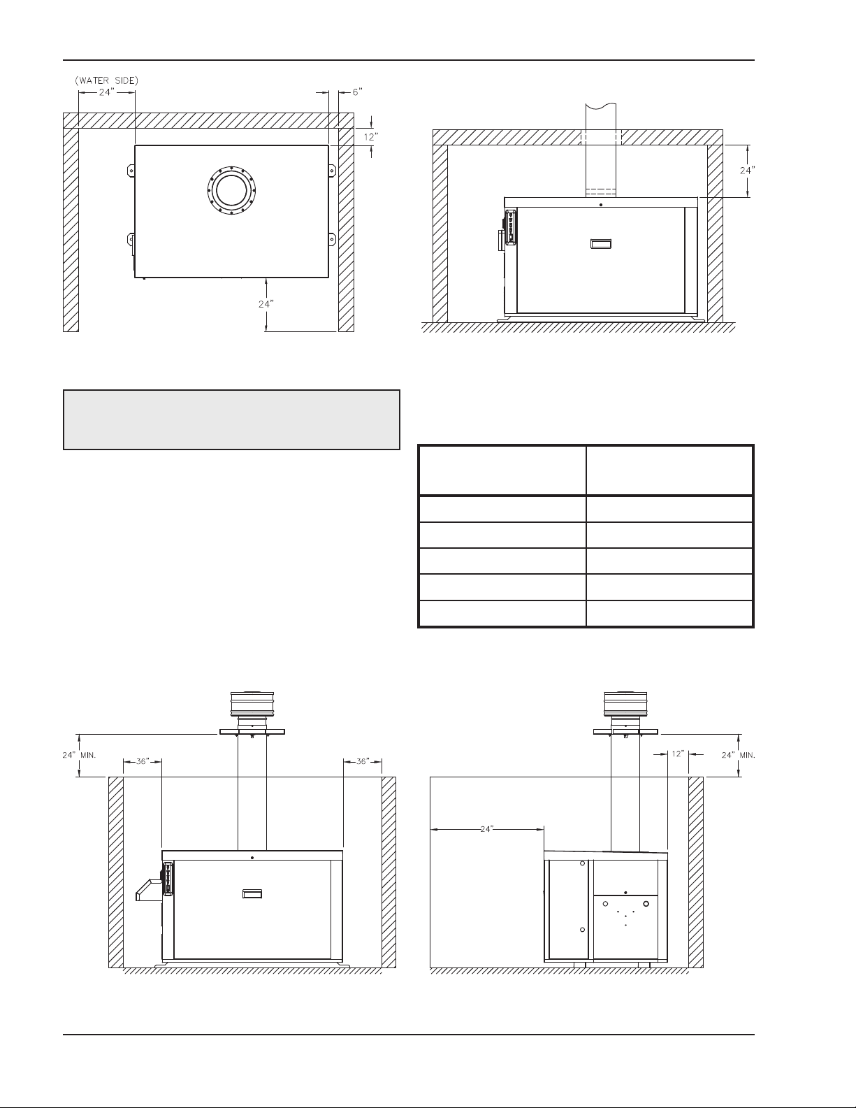
Fig. 7: Minimum Installed Service Clearances — Indoor/Closet Installations
CAUTION: Service clearances less than the
minimums may require removal of the heater to
service either the heat exchanger or the burners.
The heater must be installed in a manner that will
enable the heater to be serviced without removing any
structure around the heater.
Outdoor Installations
These heaters are design-certified for outdoor installation. Heaters must not be installed under an overhang
unless clearances are in accordance with local installation codes and the requirements of the gas supplier.
Three sides must be open in the area under the over-
hang. Roof water drainage must be diverted away
from heaters installed under overhangs.
Heater Side
Minimum Installed
Service Clearance
Front 24”
Rear 12”
Top Unobstructed
Other Side 36”
Water Side 36”
Table D: Service Clearances — Outdoor Installations
Fig. 8: Minimum Installed Service Clearance — Outdoor Installations
10

hese clearances are required when the outdoor
T
vent cap is used. If installing the heater outdoors
with a vent stack, the indoor clearances may be
utilized.
The combustion air intake hood MUST be used for
outdoor installations. The hood is shipped loose and
installed on the side of the heater over the filter box at
the job site.
Combustion and Ventilation Air
Combustion Air Filter
This heater is supplied with an integral combustion air
filter. This filter will reduce the amount of particulates
passed through the combustion system and heat
exchanger but will not protect against chemical inside
air contamination (See Appendix). The filter must be
checked periodically to verify that adequate combustion air is being supplied to the heater. See the
Maintenance section of this manual for information on
checking the filter and establishing service intervals.
nput rating of all equipment in the room when the
i
opening is communicating directly with the outdoors or through vertical duct(s). The total
cross-sectional area shall be at least 1 in.
rea per 10,000 BTUH (222 mm
a
input rating of all equipment in the room when the
opening is communicating with the outdoors
through horizontal duct(s). This opening must
meet the location requirements of the National
Fuel Gas Code.
3. In cold climates, and to mitigate potential freezeup, Raypak highly recommends the installation of
a motorized sealed damper to prevent the circulation of cold air through the heater during
non-operating hours.
2
p
2
of free
er kW) of total
Conventional Combustion Air
Supply
U.S. Installations
All Air from Inside the Building
Indoor Units
The heater must be supplied with sufficient quantities
of non-contaminated air to support proper combustion
and equipment ventilation. Combustion air can be supplied via conventional means where combustion air is
drawn from the area immediately surrounding the
heater, or via direct vent, where combustion air is
drawn directly from outside. All installations must comply with the requirements of the NFGC (U.S.) and
B149 (Canada), and all local codes.
CAUTION: Combustion air must not be
contaminated by corrosive chemical fumes which
can damage the heater and void the warranty. (See
the Appendix.)
Direct Combustion Air
If outside air is drawn through the intake pipe directly
to the unit for combustion:
1. Install combustion air direct vent in accordance
with the venting section of this manual.
2. Provide adequate ventilation of the space occupied by the heater(s) by an opening(s) for
ventilation air at the highest practical point communicating with the outdoors. The total
cross-sectional area shall be at least 1 in.
area per 20,000 BTUH (111 mm
2
per kW) of total
2
of free
The confined space shall be provided with TWO permanent openings communicating directly with an
additional room(s) of sufficient volume so that the combined volume of all spaces meets the criteria for an
unconfined space. The total input of all gas utilization
equipment installed in the combined space shall be
considered in making this determination. Each opening shall have a minimum free area of 1 in.2 per 1,000
BTUH (22 cm² per kW) of the total input rating of all
gas utilization equipment in the confined space, but
not less than 100 in.² (645 cm²). One opening shall
commence within 6-3/4 in. of the top, and one opening
shall commence within 6-3/4 in. of the bottom, of the
enclosure. The minimum dimension of air openings
shall be not less than 3 in. (8 cm) in any direction.
All Air from Outdoors
The confined space shall communicate with the outdoors in accordance with methods 1 or 2 below. The
minimum dimension of air openings shall not be less
than 3 in. (8 cm) in any direction. Where ducts are
used, they shall be of the same cross-sectional area
as the free area of the openings to which they connect.
1. Two permanent openings, one commencing
within 12 in. (30 cm) of the top, and one commencing within 12 in. (30 cm) of the bottom, of the
enclosure shall be provided. The openings shall
communicate directly, or by ducts, with the outdoors or spaces (crawl or attic) that freely
communicate with the outdoors.
11
a. Where directly communicating with the out-
doors or where communicating to the
outdoors through vertical ducts, each opening
shall have a minimum free area of 1 in.2per
4000 BTUH (5.5 cm2per kW) of total input rating of all equipment in the enclosure.
b. Where communicating with the outdoors
through horizontal ducts, each opening shall
have a minimum free area of 1 in.2per 2000
BTUH (11 cm2per kW) of total input rating of
all equipment in the enclosure.
2. One permanent opening, commencing within 12
in. (30 cm) of the top of the enclosure, shall be
permitted where the equipment has clearances of
at least 1 in. (2.5 cm) from the sides and back and
6 in. (16 cm) from the front of the appliance. The
opening shall directly communicate with the outdoors or shall communicate through a vertical or
horizontal duct to the outdoors or spaces (crawl or
attic) that freely communicate with the outdoors,
and shall have a minimum free area of:
a. 1 in.2per 3000 BTUH (7 cm2per kW) of the
total input rating of all equipment located in the
enclosure, and
b. Not less than the sum of the areas of all vent
connectors in the confined space.
WARNING: Do not use one permanent opening
method if the equipment room is under negative
pressure conditions or the equipment is common
vented with other gas-fired appliances.
Installations in Canada
air flow from the outdoors for natural draft, partial
fan assisted, fan-assisted or power draft-assisted
burners, there shall be a permanent air supply
opening(s) having a cross section area of not less
than 1 in.2per 7000 BTUH (310 mm2per kW) up
to and including 1 million BTUH, plus 1 in.2per
14000 BTUH (155 mm2per kW) in excess of 1 million BTUH. This opening(s) shall be either located
at or ducted to a point not more than 18 in. (450
mm) nor less than 6 in. (150 mm) above the floor
level. The duct can also "Goose Neck" through the
roof. The duct is preferred straight down 18” from
floor, but do not place near piping. This air supply
opening requirement shall be in addition to the air
opening for ventilation air required in (1).
3. For heaters not using a barometric damper in the
vent system, and when air supply is provided by
natural air flow from outdoors for a power burner
and there is no draft regulator, drafthood or similar
flue gas dilution device installed in the same
space, in addition to the opening for ventilation air
required in (1), there shall be a permanent air supply opening(s) having a total cross-sectional area
of not less than 1 in.2for each 30,000 BTUH (70
mm2per kW) of total rated input of the burner(s),
and the location of the opening(s) shall not interfere with the intended purpose of the opening(s)
for ventilation air referred to (1). This opening(s)
can be ducted to a point not more than 18 in. (450
mm) nor less than 6 in. (150 mm) above the floor
level. The duct can also "Goose Neck" through the
roof. The duct is preferred to be straight down 18”
from floor, but do not place near piping.
4. Refer to the latest version of the B149 for additional information.
CAUTION: All combustion air must be drawn from
the air outside of the building; the mechanical
equipment room must communicate directly with the
outdoors.
1. Ventilation of the space occupied by the heater
shall be provided by an opening(s) for ventilation
air at the highest practical point communicating
with outdoors. The total cross-sectional area of
such an opening(s) shall be at least 10% of the
area required in (2) and (3), but in no case shall
the cross-sectional area be less than 10 in.
mm2.).
2. For heaters using a barometric damper in the vent
system, and when air supply is provided by natural
2
(6500
Water Piping
General
The heater should be located so that any water leaks
will not cause damage to the adjacent area or struc-
tures.
CAUTION: This heater requires forced water
circulation when the burner is operating. See Table E
and Table F for minimum and maximum flow rates
and water pump selection. The pump must be
interlocked with the heater to prevent heater
operation without water circulation.
12
Reversing Water Connections
Follow these instructions to change the water connections from the left-hand side (standard) to the
right-hand side. This is an ASME-Certified pressure
essel. It is the installer’s responsibility to ensure that
v
the pressure vessel is properly sealed after making
these changes.
1. Disconnect all electrical power from the heater (if
applicable).
2. Label all electrical connections and conduit lines.
This may include the flow switch, low water cut-off
probe and/or pump.
3. Disconnect or isolate the main gas pipe from the
heater (if applicable).
4. Remove both in/out and return header access
panels by removing all sheet metal screws.
5. Remove all plumbing fittings to the header. This
will include both inlet and outlet water pipe unions
and the pressure relief valve and drain piping.
6. Remove limits, control bulbs and/or sensors.
7. Remove the six flange nuts and the in/out header
from the left-hand side.
8. Remove the six flange nuts and the return header
from the right-hand side.
9. Remove the header stud bolts from each tube
sheet.
10. Reverse the headers and stud bolts to the new
location.
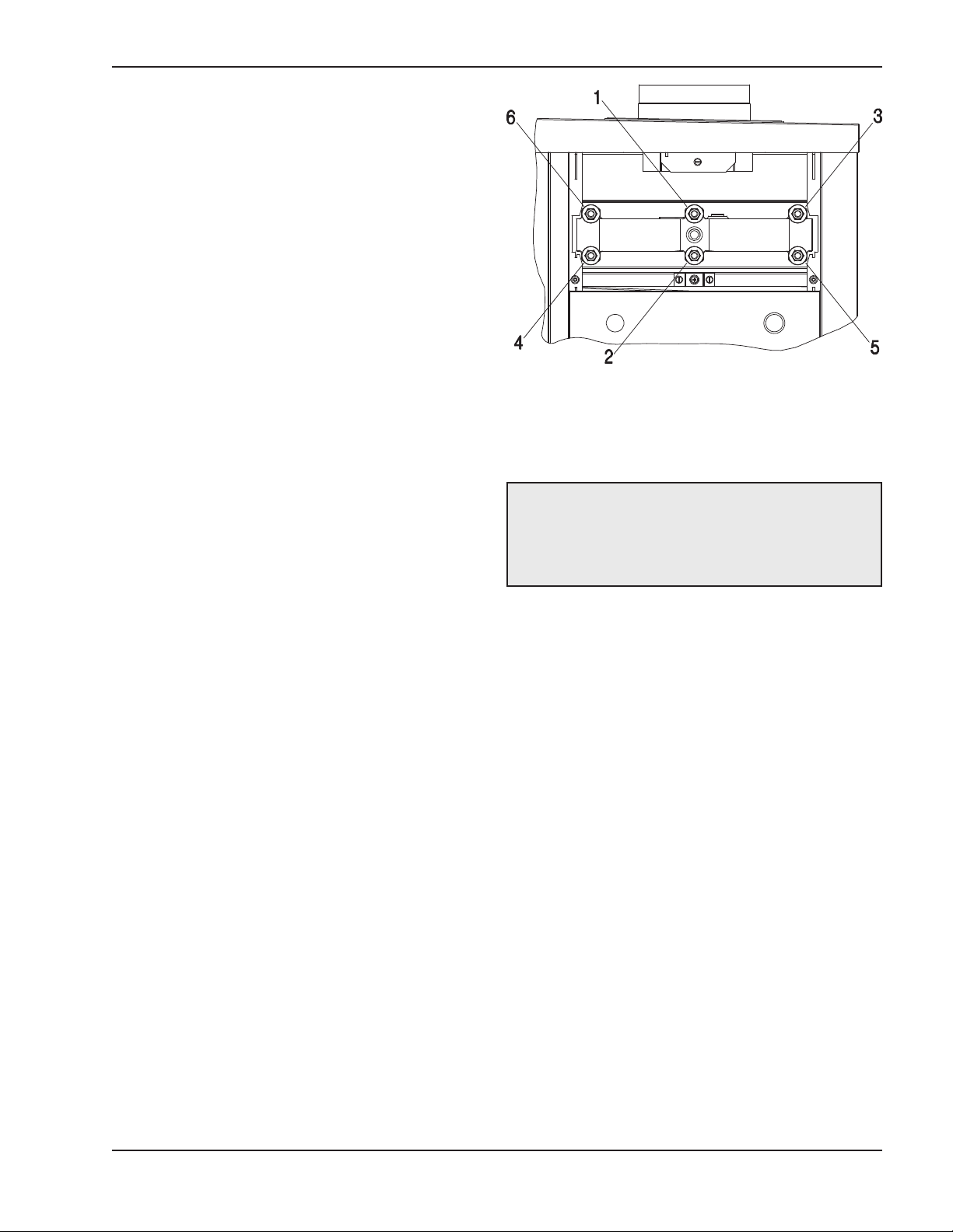
Fig. 9: Torque Sequence
Relief Valve Piping
WARNING: Pressure relief valve discharge piping
must be piped near the floor and close to a drain to
eliminate the potential of severe burns. Do not pipe
to any area where freezing could occur. Refer to
local codes.
11. Install NEW red beveled O-rings flush against both
tube sheets with the bevel facing outward.
12. Push the header firmly against the O-rings. Install
and tighten the flange nuts onto the stud bolts until
finger tight.
13. Slowly tighten the flange nuts, starting from the
center nut (number 1) in Fig. 9 and working
sequentially around the header as indicated.
Torque all nuts to 25 ft/lb. DO NOT OVER-TIGHT-
EN.
14. Re-route the capillary(s), wiring, etc., to the new
location, adding thermal paste and shim to the
capillary well.
13
Hydrostatic Test
Temperature & Pressure Gauge
Unlike many other types of heaters, Raypak heaters
do not require hydrostatic testing prior to being placed
in operation. The heat exchanger has already been
actory-tested and is rated for 160 PSI maximum oper-
f
ating pressure. However, Raypak does recommend
hydrostatically testing the piping connections to the
heater and the rest of the system prior to operation.
This is particularly true for hydronic systems using
expensive glycol-based antifreeze. Raypak recommends conducting the hydrostatic test before
connecting gas piping or electrical supply.
Leaks must be repaired at once to prevent damage to
the heater. NEVER use petroleum-based stop-leak
compounds.
1. Connect fill water supply. Fill heater with water (be
sure bleed valve is open). When water flows from
bleed valve, shut off water. Close bleed valve.
Carefully fill the rest of the system, being sure to
eliminate any entrapped air by using high point
vents. Close feed valve. Test at standard operating
pressure for at least 24 hours.
2. Make sure constant gauge pressure has been
maintained throughout test.
The temperature and pressure gauge is shipped loose
for field installation.
Hydronic Heating
System Design
Hot water heating systems all have unique levels of
operating diversity. Raypak equipment design utilizes
as little water mass as possible to ensure maximum
operating efficiency. Primary / Secondary piping
arrangement is the method recommended and the
only method supported by Raypak for installation of
Raypak heating equipment. Proper system design
should always include system flow in excess of the
connected boiler flow for proper operation
(Boiler Flow + 15% = Min. System Flow). When
appropriate, a Buffer/De-coupler Tank can be used
where system flow may be reduced below the connected boiler flow. Failure to design for adequate
system flow (i.e. bypasses, 3-way control valves, flow
limiting balance devices, buffer tanks, etc.) will result in
boiler short-cycling and poor system performance.
Always contact your local Raypak representative for
system design assistance to avoid these issues.
3. Check for leaks. Repair if found.
Low Temperature System
Heater requires minimum inlet temperature of 105°F.
Consult the following sections for piping details.
Model
No.
HD101 100 85 17 1.3 13 0.7 14 44 8.8 4
HD151 150 128 26 3.0 13 0.7 13 0.7 20 44 8.8 6
HD201 199 169 34 5.3 17 1.3 13 3.4 27 44 8.9 8
HD251 250 213 44 9.2 21 2.1 14 1.0 13 0.7 34 44 9.2 10
HD301 299 254 25 3.1 17 1.4 13 0.8 40 44 9.4 12
HD401 399 335 34 5.6 22 2.5 17 1.4 40 44 9.8 15
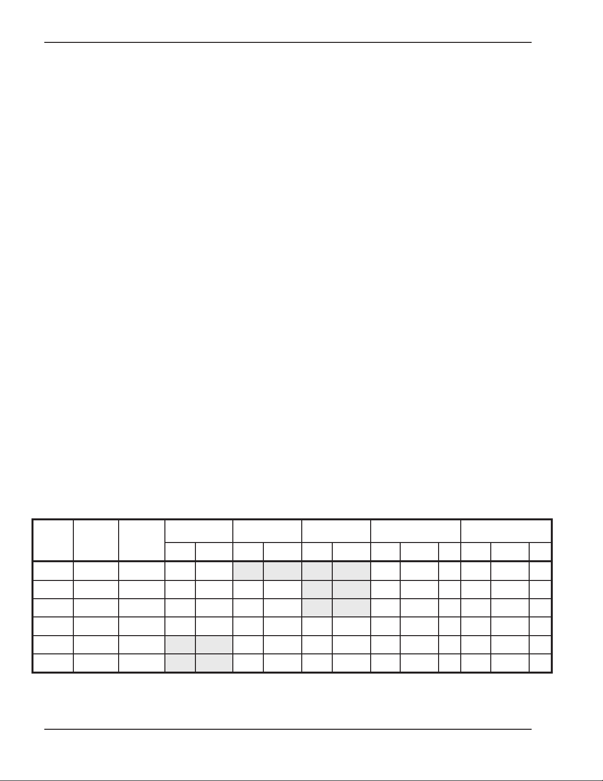
*Flow switch will not activate at less than 12 gpm.
NOTE: Basis for minimum flow — 13 gpm or 40°F ∆T maximum flow — gpm, except for header.
Input
MBTUH
Output
MBTUH
10°F T 20°F T 30°F T Min. Flow Max. Flow
gpm P (ft) gpm P (ft) gpm P (ft) gpm P (ft) T gpm P (ft) T
Pump Selection
In order to ensure proper performance of your boiler
system, you must install a properly-sized pump.
Raypak recommends using a 20°F ∆T as design ∆T.
(∆T is the temperature difference between the inlet
and outlet water when the heater is firing at full rate).
If a ∆T other than 20°F is necessary, see Table E for
flow rate requirements.
Table E: Heater Rates of Flow and Pressure Drops
14
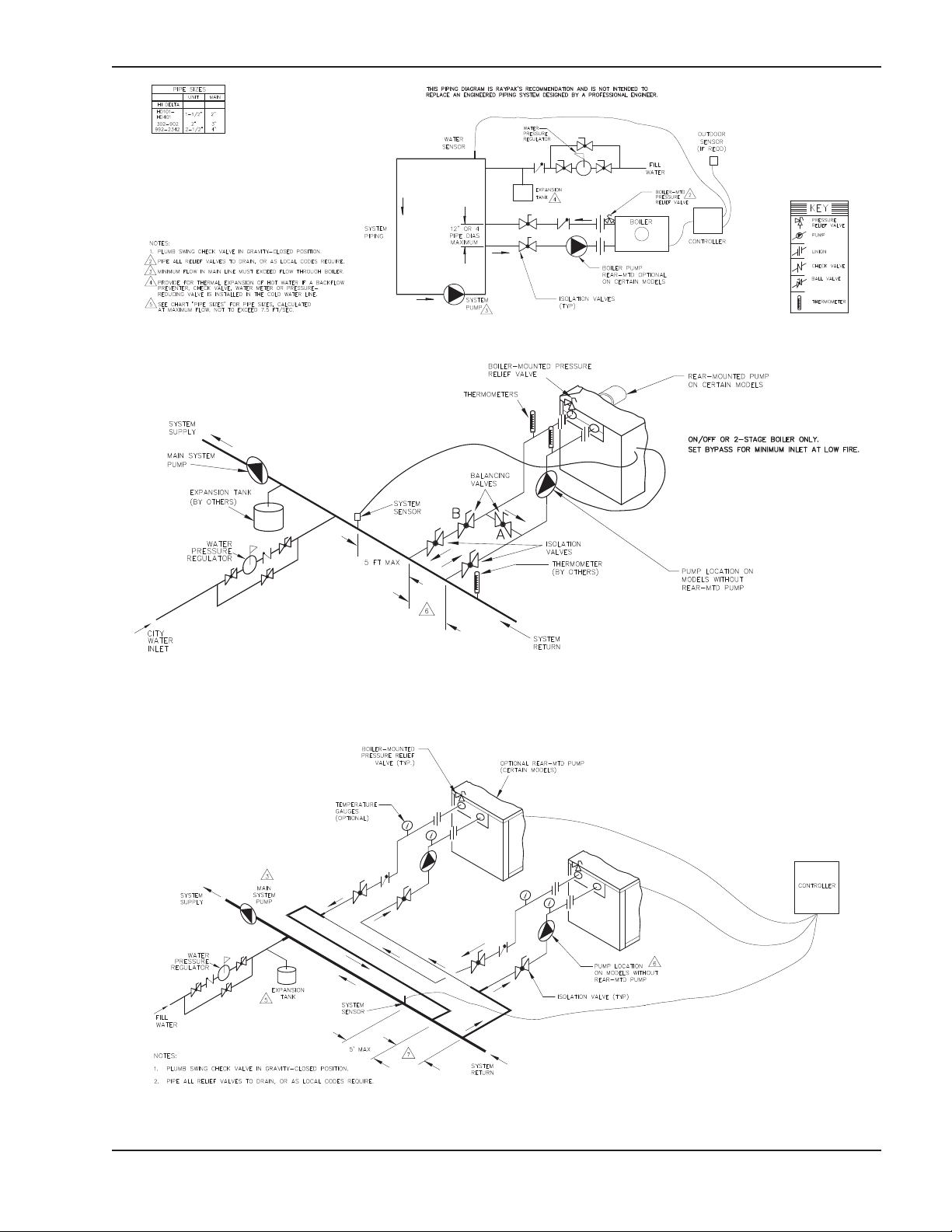
Fig. 10: Single Boiler — Primary/Secondary Piping
*Maximum 4 times the pipe diameter or 12”, Max.
Fig. 11: Single Boiler — Low-Temperature Application (Heat Pump) Primary/Secondary Piping
*Maximum 4 times the pipe diameter or 12”, Max.
Fig. 12: Dual Boiler—Primary/Secondary Piping
15

Pressure Drop in Feet of Head
Feedwater Regulator
Raypak recommends that a feedwater regulator be
installed and set at 12 psi minimum pressure at the
highest point of system. Install a check valve or back
low device upstream of the regulator, with a manual
f
shut off valve as required by local codes.
Piping—Heating Boilers
All high points should be vented. Purge valves and a
bypass valve should be installed. A boiler installed
above radiation level must be provided with a low
water cut-off device. The boiler, when used in connection with a refrigeration system, must be installed so
the chilled medium is piped in parallel with the boiler
with appropriate valves to prevent the chilled medium
from entering the boiler.
System flow must always exceed boiler flow for proper
operation. Raypak strongly recommends a minimum
system flow of 115% of the boiler flow.
Air-Separation/Expansion Tank
All boilers should be equipped with a properly sized
expansion tank and air separator fitting as shown in
the piping diagrams (Fig. 10–13).
Three-Way Valves
Valves designed to blend water temperatures or
reduce water circulation through the boiler should not
be used. Raypak boilers are high recovery low mass
boilers not subject to thermal shock. Raypak offers a
full line of electric sequencers that produce direct reset
of boiler water temperature. Refer to the Controls
Section in our Complete Catalog.
The boiler piping system of a hot water heating boiler
Domestic Hot Water Piping
connected to heating coils located in air handling units
where they may be exposed to circulating refrigerated
air, must be equipped with flow control valves or other
automatic means to prevent gravity circulation of the
boiler water during the cooling cycle. It is highly recommended that the piping be insulated.
Model
No.
HD101 100 85 9 20 1.8 1-1/2 3.8 7 26 3.0 1-1/2 6.3 4 45 9.2 1-1/2 18.0
HD151 150 128 13 20 1.8 1-1/2 3.8 10 26 3.1 1-1/2 6.3 6 45 9.2 1-1/2 18.1
HD201 199 169 17 20 1.9 1-1/2 3.9 13 26 3.2 1-1/2 6.4 8 45 9.4 1-1/2 18.2
HD251 250 213 21 20 1.9 1-1/2 3.9 16 26 3.2 1-1/2 6.5 9 45 9.6 1-1/2 18.5
HD301 299 254 25 20 1.9 1-1/2 3.9 20 26 3.2 1-1/2 6.5 11 45 9.8 1-1/2 18.7
HD401 399 339 34 20 2.0 1-1/2 4.0 26 26 3.3 1-1/2 6.6 15 45 10.3 1-1/2 19.1
∆T = Temperature rise, °F.
∆P = Pressure drop through heat exchanger, ft.
SHL = System head loss, ft. (System head loss is based on the heater and tank placed no more than 5 feet apart and 50 feet equivalent length
of tubing and fittings.)
gpm = Gallons per minute, flow rate.
MTS = Minimum tubing size.
*Must utilize optional cupro-nickel tubes.
**With Hard Water (16-25 grains per gallon), the operating control must be set no higher than 130°F for scale free operation. For operating temperatures above 130°F, a water softener must be utilized.
Input
MBTUH
Output
MBTUH
Soft (0–4 grains per gallon) Medium (5–15 grains per gallon) Hard* (16–25** grains per gallon)
T gpm P MTS SHL T gpm P MTS SHL T gpm P MTS SHL
When designing the water piping system for domestic
water applications, water hardness should be considered. Table F indicates the suggested flow rates for
soft, medium and hard water. Hardness is specified as
grains per gallon.
Table F: Domestic Water Heater Flow Rate Requirements
16
 Loading...