


CATALOG NO. 6100.61E
Effective: 02-01-05
Replaces: 03-01-03
INSTALLATION
AND OPERATING
INSTRUCTIONS
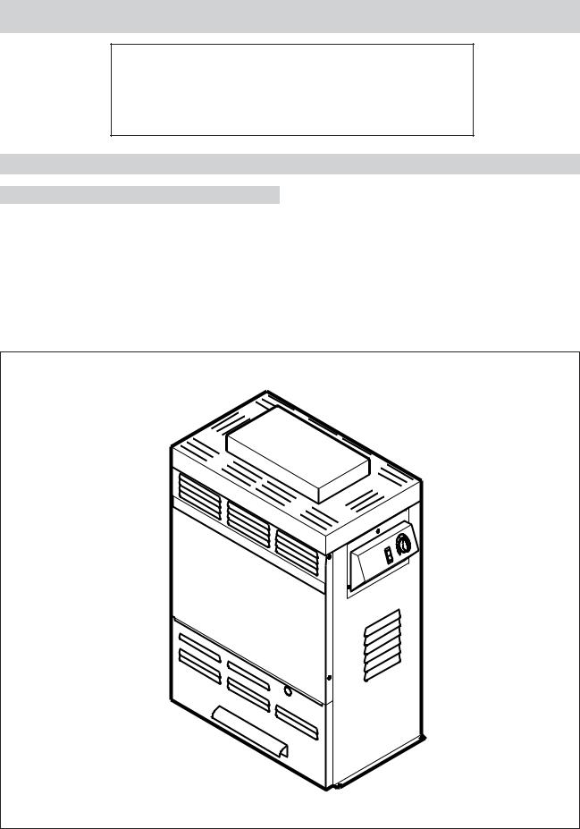
Models
105B Brass
VERSA
ABOVE GROUND POOL and
SPA HEATER
WARNING: If the information in these instructions are not followed exactly, a fire or explosion may result causing property damage, personal injury or death.
—Do not store or use gasoline or other flammable vapors and liquids in the vicinity of this or any other appliance.
—WHAT TO DO IF YOU SMELL GAS
•Do not try to light any appliance.
•Do not touch any electrical switch; do not use any phone in your building.
•Immediately call your gas supplier from a neighbor's phone. Follow the gas supplier's instructions.
•If you cannot reach your gas supplier, call the fire department.
—Installation and service must be performed by a qualified installer, service agency or the gas supplier.
This manual should be maintained in legible condition and kept adjacent to the heater or kept in a safe place for future reference.
Part No. 240790


Contents
4PART ONE - Owner's Operating Instructions
4SECTION 1 / START-UP PROCEDURES
4BeforeStart-Up
5Lighting Instructions & Shut-Off Procedures (manually lighted pilot MV)
6Operating Instructions & Shut-Off Procedures (automatically lighted pilot IID)
7After Start-Up
7SECTION 2 / CAUTION
7SECTION 3 / MAINTENANCE& CARE PROCEDURES
8 Pool & Spa Water Chemistry
8 Winterizing the Pool and Spa Heater
9PART TWO - Installation / Service Instructions
9SECTION 1 / RECEIVING EQUIPMENT
9SECTION2/GENERALSPECIFICATIONS
9SECTION 3 / INSTALLATION INSTRUCTIONS
9CodeRequirements
9Base Installation
10Clearances
11Combustion Air
12Venting Connections
14Gas Supply Connections
15Plumbing for Water Connections
17Electrical Wiring
21 |
SECTION 4 / SERVICING INSTRUCTIONS |
21 |
General Location of Controls |
21Control Adjustments / Replacements
21Pressure Switch
22High Limit
22Pilot Safety
23BurnerDrawerRemoval
23 |
GasValveRemoval |
23 |
Main Burner & Orifice Removal |
23 |
Pilot Removal & Cleaning |
23Heat Exchanger Removal
24TubeCleaningProcedure
24 |
TubeReplacementProcedure |
24 |
Desooting Procedure |
24CombustionChamberRemoval
25Immersion Well Removal
25UnithermGovernorRemoval
26SECTION 5 / TROUBLESHOOTING GUIDE
26Mechanical
27Electrical MV Units
28Electrical IID Units
29SECTION 6 / REPLACEMENT PARTS
3
PART ONE - OWNER'S OPERATING INSTRUCTIONS
FOR YOUR SAFETY - READ BEFORE OPERATING
WARNING: IF YOU DO NOT FOLLOW THESE
INSTRUCTIONS EXACTLY, A FIRE OR EXPLOSION
MAYRESULT,CAUSINGPROPERTYDAMAGE,
PERSONAL INJURY OR LOSS OF LIFE.
SECTION 1- START-UP PROCEDURES
BEFORE START-UP
BURNERS
Clean main burners and air louvers of dust, lint and debris. Keep heater area clear and free from combustibles, flammable liquids and chemicals. Do not obstruct the flow of combustion and ventilating air.
WATER
First thing, insure that system is filled with water and havepumpoperating.Watermustbeflowingthroughthe heater during operation.
Fig. #9258
4
CAUTION: Propane gas is heavier than air and will settle on the ground. Since propane can accumulate in confined areas, extra care should be exercised when lighting propane heaters.
LIGHTING INSTRUCTIONS AND SHUT-OFF PROCEDURES MANUALLY LIGHTED PILOTS
( MILLIVOLT SYSTEM)
A.This appliance has a pilot that must be lighted by hand. When lighting the pilot, follow these instructions exactly.
B.BEFORE LIGHTING smell all around the appliance area for gas. Be sure to smell next to the floor because some gas is heavier than air and will settle on the floor.
WHAT TO DO IF YOU SMELL GAS:
*Do not try to light any appliance.
*Do not touch any electric switch; do not use any phone in your building.
*Immediately call your gas supplier from a neighbor's phone. Follow the gas supplier's instructions.
*If you cannot reach your gas supplier, call the fire department.
C.Use only your hand to push in or turn the gas control knob. Never use tools. If the knob will not push in or turn by hand, do not try to repair it. Call a qualified service technician. Force or attempted repair may result in a fire or explosion.
D.Do not use this appliance if any part has been underwater. Immediately call a qualified service technician to inspect the appliance and to replace any part of the control system and any gas control which has been under water.
LIGHTING INSTRUCTIONS
1.STOP! Read the safety information above.
2.Set the thermostat on the lowest setting.
3.Turn On/Off switch to the "Off" position.
4.Remove heater door panel.
5.Push in gas control knob slightly and turn clockwise  to "Off".
NOTE: Knob cannot be turned from "Pilot" to "Off" unless knob is pushed in slightly. Do not force.
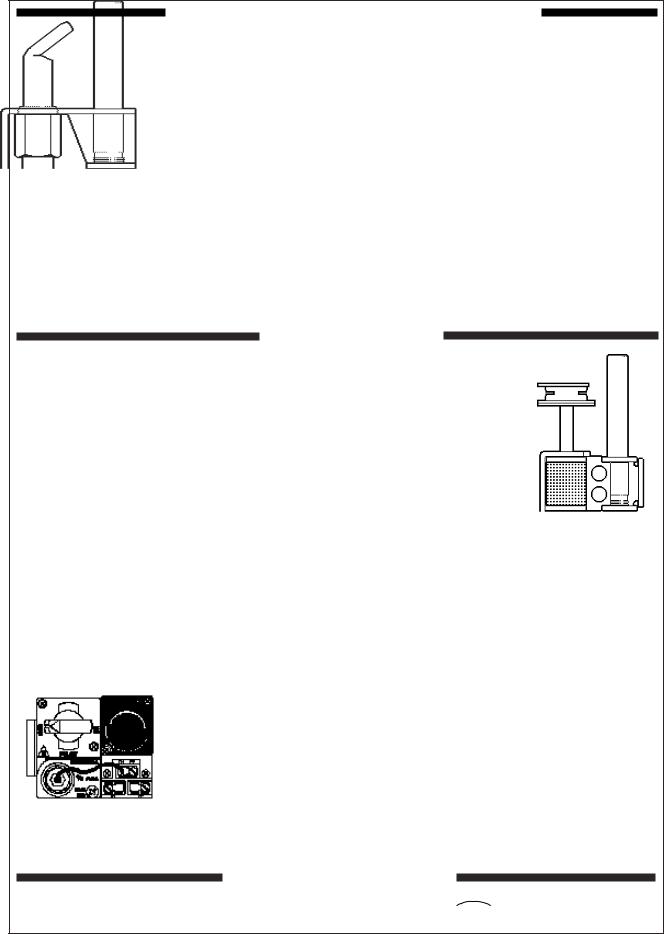
ROBERTSHAW PILOT |
HONEYWELL PILOT |
6.Wait 5 minutes to clear out any gas. If you then smell gas, STOP! Follow "B" in the safety information above. If you don't smell gas, go to the next step .
7.Locate pilot mounted on the right side panel of the burner drawer. For burner drawer location, see location of control section, page 18.
Gas control knobs shown in "Off" position
HONEYWELL |
ROBERTSHAW |
GAS VALVE |
GAS VALVE |
MILLIVOLT |
MILLIVOLT |
Fig. #8081.0 |
Fig. # 8199 |
Fig. #8084.0 |
Fig. #8083.0 |
8.Turn knob on gas control counter-clockwise
 to "Pilot".
9.Push in control knob all the way and hold in. Immediately place flame to pilot to light. Continue to hold control knob in for about 1 minute after the pilot is lighted, release knob and it will pop back up. Pilot should remain lighted. If it goes out, repeat steps 5 through 9. *If knob does not pop up when released, stop and immediately call your service technician or gas supplier.
*If the pilot does not stay lit after several tries, turn the gas control knob to "Off" and call your
service technician or gas supplier.
10.Stand to the side of the heater and turn the gas control knob counter clockwise to  "On".
"On".
11.Replace heater door panel.
12.Turn On/Off switch to the "On" position.
13.Set thermostat to the desired setting.
TO TURN OFF GAS TO APPLIANCE
4. Push the gas control knob slightly and turn clockwise to  "Off". Do not force.
5. Replace heater door panel.
5
CAUTION: Propane gas is heavier than air and will settle on the ground. Since propane can accumulate in confined areas, extra care should be exercised when lighting propane heaters.
OPERATING INSTRUCTIONS AND SHUT-OFF PROCEDURES
AUTOMATICALLY LIGHTED PILOTS
(ELECTRONIC IGNITION SYSTEMS)
A.This appliance is equipped with an ignition device which automatically lights the pilot. Do not try to light the pilot by hand.
B.BEFORE OPERATING, smell all around the appliance area for gas. Be sure to smell next to the floor because some gas is heavier than air and will settle on the floor.
WHAT TO DO IF YOU SMELL GAS:
*Do not try to light any appliance.
*Do not touch any electric switch; do not use any phone in your building.
*Immediately call your gas supplier from a neighbor's phone. Follow the gas supplier's instructions.
*If you cannot reach your gas supplier, call the fire department.
C.Use only your hand to push in or turn the gas control knob. Never use tools. If the
knob will not push in or turn by hand, do not try to repair it; call a qualified service technician. Force or attempted repair may result in fire or explosion.
D.Do not use this appliance if any part has been under water. Immediately call a qualified service technician to inspect the appliance and to replace any part of the control system and any gas control which has been under water.
OPERATING INSTRUCTIONS
1.STOP! Read the safety information above.
2.Set the thermostat to the lowest setting.
3.Turn off all electric power to the appliance.
4.This appliance is equipped with an ignition device which automatically lights the pilot. Do not try to light the pilot by hand.
5.Remove heater door panel.
6. Turn gas control knob clockwise |
to "Off". |
7.Wait 5 minutes to clear out any gas. If you then smell gas, STOP! Follow "B" in the safety information previously stated. If you don't smell gas, go to the next step.
8.Turn gas control knob counter-clockwise  to "On".
9.Replace heater door panel.
10.Turn on all electrical power to appliance.
11.Set thermostat to desired setting.
12.If the appliance will not operate, follow the instructions "To Turn Off Gas To Appliance" and call your service technician or gas supplier.
Gas control knob shown in "ON" position.
GAS
INLET
HONEYWELL VR8300 GAS VALVE IID
TO TURN OFF GAS TO APPLIANCE
1.Set the thermostat at the lowest setting.
2.Turn off all the electric power to the appliance if service is to be performed.
3.Remove heater door panel.
4. |
Turn gas control knob clockwise |
|
to "Off". |
|
|||
|
Make sure knob rest against stop. |
|
|
|
|
|
|
5. |
Replace heater door panel. |
|
|
6
AFTER START-UP
Feel the inlet and outlet pipes. Outlet pipe should be only slightly warmer than the inlet. It should not be hot.
WARNING: Should overheating occur or the gas supply fail to shut off, turn off the manual gas control valve to the appliance.
VISUALINSPECTION
With the heater on, remove the door and make a visual check of the pilot and burner.
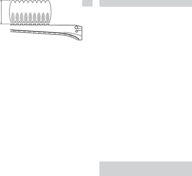
Theflameshouldbebluewithawell-definedpattern.
4" MAX
Fig. # 8144.1
MAIN BURNER FLAME
Fig. # 8958
PILOT BURNER FLAME
A yellow or "floating" flame indicates restricted air openings or incorrect orifice size. Should this occur, shut the heater off and contact your installer or gas supplier.
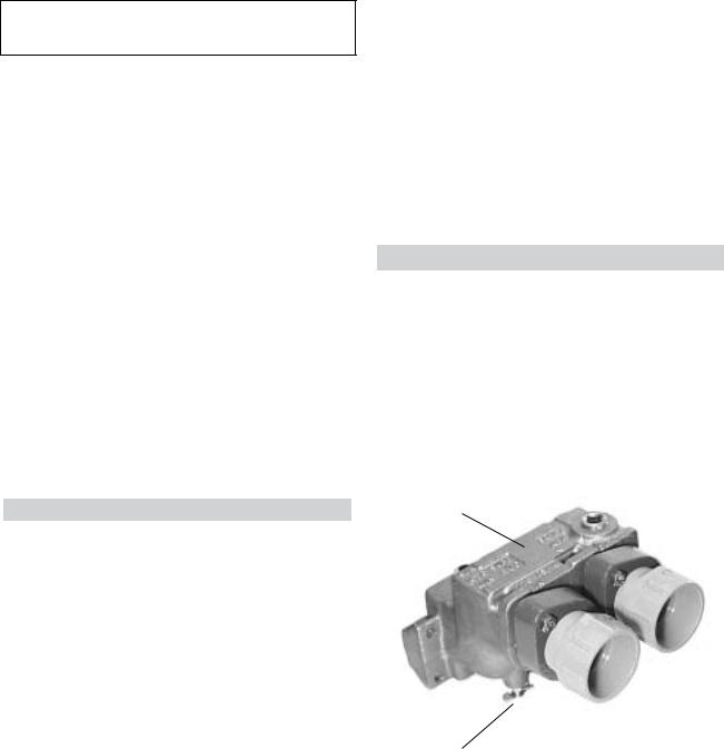
WATER PRESSURE SWITCH
A water pressure switch is provided in the heater to shut off the burners in the event that water supply to the heater is interrupted. It is very important to verify that the switch electrically opens and shuts off the gas valve when water flow to the heater is interrupted. Otherwise, rapid and severe damage will likely occur to the heater. (The water pressure switch should be checked and adjusted for proper operation by a qualified service person at the time of installation and periodically checked thereafter. Refer to pressure switch servicing instruction in Section 4 of this manual.)
WARNING: Operation of the heater without water circulation will cause rapid and severe damage to the heater.
SECTION 2 / CAUTION
Elevated water temperature can be hazardous, and the U.S. Consumer Product Safety Commission recommends the following guidelines:
1.Spa or hot tub water temperatures should never exceed 104°F (40°C). A temperature of 100°F (38°C) is considered safe for a healthy adult. Special caution is suggested for young children.
2.Drinking of alcoholic beverages before or during spa or hot tub use can cause drowsiness which could lead to unconsciousness and subsequently result in drowning.
3.Pregnant women beware! Soaking in water over 102° F (39°C) can cause fetal damage during the first three months of pregnancy, (resulting in the birth of a brain damaged or deformed child). Pregnant women should stick to the 100°F (38°C) maximum rule.
4.Before entering the spa or hot tub, users should check the water temperature with an accurate thermometer; spa or hot tub thermostats may err in regulating water temperatures by as much as four degrees Fahrenheit (2.2°C).
5.Persons with a medical history of heart disease, circulatory problems, diabetes, or blood pressure problems should obtain a physician's advice before using pools or hot tubs.
6.Persons taking medications which induce drowsiness, such as tranquilizers, antihistamines, or anticoagulants, should not use spas or hot tubs.
SECTION 3 / MAINTENANCE AND CARE PROCEDURES
To be followed one month after start-up and then semi-annually.
1.Inspect top of heater and draft hood for soot, (a sticky black substance around finned tubes, baffle and open flue gas passageways).
CAUTION: Soot may be combustible. Wet sooted surfaces completely prior to cleaning. Do not use steel wire brush.
2.Clean main burners and pilot burner of dust and lint.
3.Inspect and operate all controls, gas valve and pressurereliefvalve.
7
4.Make visual check of the burner and pilot flame. Flame pattern on the main burner and pilot is indicated in the previous illustration. Yellow flame means restriction of the air openings. Lifting or blowing flame indicates high gas pressure. Low flame means low gas pressure. Should this occur, shut the heater off and contact your gas supplier or qualified service agency.
5.On indoor heaters, clean room intake openings to assure adequate flow of combustion and ventilation air.
CAUTION: Combustion air must not be contaminated corrosive chemical fumes which can damage the heater.
6.Keep area around heater clear and free from combustible materials and other flammable and corrosive vapors and liquids.
BASIC TIPS IF HEATER WILL NOT FIRE:
1.If you have no electrical power; it may be your "circuit breakers" have tripped. Try re-setting them.
2.if you have electrical power but the heater will not fire
check the following:
3.The time clock must be moved to the "ON" position.
4.Your pump strainer basket may be full. If so remove debris.
5.your filter may be dirty. If so, backwash or clean filter.
(To tell if your filter is dirty, the gauge pressure will be higher than usual).
6.The pump amy have lost it's prime. It may be running dry, check the pressure gauge on the filter. If there is no pressure; then you are not moving water (or your gauge is broken). Try to get the pump to run at it's normal flow rate.
POOL & SPA WATER CHEMISTRY
Chemical imbalance can cause severe damage to your heater and associated equipment. Maintain your water chemistry according to the chart on page 2. If the mineral content and dissolved solids in the water become too high, scale forms inside the heat exchanger tubes, reducing heater efficiency and also damaging the heater. If the pH drops below 7.2, the heater will be severly damaged. This will result in corrosion of the heat exchanger. Heat exchanger damage resulting from chemical imbalance is not covered by the warranty.
COLDWEATHEROPERATION
MODERATECLIMATE:Heateroperationcancontinue during short term cold spells. When temperatures are below freezing, flow (continuous pump operation) must be maintained.
CAUTION: Do not use the heater to maintain water temperatures just above freezing or for freeze protection. When heaters are used during freezing weather care must be taken to avoid freeze ups. Continuous pump operation is a must. Additional protection may be required. Theheaterisnotwarrantedagainstfreezeups.
COLD CLIMATE: Prolonged operation with water temperatures below 50°F is not recommended. When starting the heater with pool temperatures below 50°F, operate the heater continuously until higher temperatures are reached. Operating the heater for prolonged periods with pool water below 50° can seriously damage the heater, and is not covered by the warranty.
For cold climate areas please follow the winterizing procedures listed below.
WINTERIZING THE SPA HEATER
When heaters installed outdoors in freezing climate areas are to be shut down for the winter, observe the following step-by-step procedure:
1.Turn off gas valve, manual gas valve, and electrical supply to the heater.
2.Open drain cock located on the inlet/outlet header, (under water pipes)
IN/OUT
HEADER
Fig. # 9272
DRAIN VALVE
8

PART 2 - INSTALLATION / SERVICE INSTRUCTIONS
SECTION 1
RECEIVINGEQUIPMENT
On receipt of your equipment it is suggested that you visually check for external damage to the carton. If the carton is damaged, a note should be made on the Bill of Lading when signing for equipment. Remove the heater from the carton and if it is damaged, report the damage to the carrier immediately.
On occasion, we ship some items loose. Be sure that you receive the number of packages indicated on the Bill of Lading.
When ordering parts, you must specify model and serial number of heater. When ordering under warranty conditions, you must also specify date of installation.
The manufacturer recommends that this manual be reviewed thoroughly before installing your pool/spa heater. If there are any questions that this manual does not answer, please contact the factory or your local
representative.
SECTION 2
GENERALSPECIFICATION
These heaters are design certified and tested under the requirements of ANSI Z21.56/CSA 4.7 American National Standard / CSA Satndard for gas-fired Pool Heaters.
Theheaterisinterchangeableandcanbeusedeither indoor or outdoors. The appropriate top designated for that type of use is required. If desired, the top can be changed at a later date to change from outdoor to indoor or vice versa. Millivolt heaters contain a self-generating electrical system operating between .25 and .75 volts.
AMBIENTTEMPERATURERATINGOFHEATERCOMPONENTS
Millivolt Heater with Honeywell Gas Valve +32°F to+175°F
Millivolt Heater with Robertshaw Gas Valve 0°F to +175°F
Electronic Ignition Heaters* -32°F to +175°F
*Requires 120V or 240V power supply
Ratedinputssuitableforupto2000feetelevation.For elevations above 2000 feet, reduce input 4% for each 1000 feet above sea level, as high elevation reduces combustionperformance.
SECTION 3
INSTALLATION INSTRUCTIONS
CALIFORNIA PROPOSITION 65
WARNING:
This product contains chemicals known to the State of California to cause cancer, birth defects or
otherreproductive harm.
IMPORTANTNOTICE
These instructions are intended for the use of qualified personnel only, specifically trained and experienced in the installation of this type of heating equipment and related system components. Installation and service personnel may be required by some states to be licensed. If your state is such, be sure your contractor bears the appropriate license. Persons not qualified shall not attempt to fix this equipment nor attempt repairs according to these instructions.
WARNING: Improper installation, adjustment, alteration, service or maintenance may damage the equipment, create a hazard resulting in asphyxiation, explosion or fire, and will void the warranty.
CODE REQUIREMENTS
NOTE: The heater should not be located in an area where possible water leakage will result in damage to the area adjacent to the appliance or to the structure. When such locations cannot be avoided, it is recommended that a suitable drain pan, adequately drained, be installed under the appliance. The pan must not restrict combustion air flow.
Installation must be in accordance with local codes, or, in the absence of local codes, with the latest editions of the National Fuel Gas Code, ANSI Z223.1, and the National Electrical Code, ANSI/NFPA 70.
BASE INSTALLATION
Heater must be mounted on a level surface. It can be installed on combustible flooring. Heaters must not be installed on carpeting.
WARNING: Do not install within 3 feet of a Heat Pump or an outdoor condensing unit. Strong air intake from these equipment can disturb the combustion process and cause damage or personal injury.
9
CLEARANCES
ALLHEATERS
For clearances from combustible surfaces, see chart below.
Clearances from Combustible construction. IndoorInstallation:
Top* (Drafthood) - 30"; Vent - 6"; Back - 5"; Right Side - 6";
Left Side - 6"; Floor - 0. Outdoor Installation:
Top* (Stackless Top) - unobstructed; Back - 5"; Sides - 6".
* Clearance from Top of Vent Terminal
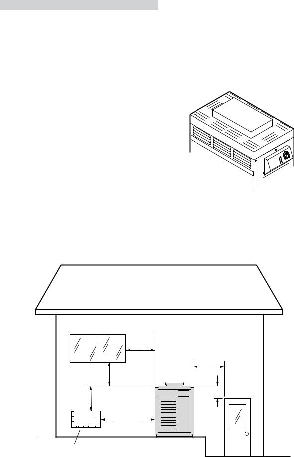
For servicing, provide at least 24" in front of the heater for burner tray removal, and at least 18" on the left side of the heater to inspect and delime the heat exchanger.
OUTDOORHEATERS
These heaters are design certified for outdoor installation, when equipped with the approved top designated for outdoor use.
WARNING: The heater shall not be located in an area where water sprinklers, or other devices, may cause water to spray through the cabinet louvers and into the heater. This could cause heavy internal rusting or damage some electrical components, and this would void the warranty.
Heater with outdoor top |
Fig # 9259 |
Heaters must not be installed under an overhang of less than three (3) feet from the top of the heater. Three
(3) sides must be open in the area under the overhang. Roof water drainage must be diverted away from the heaters installed under overhangs with the use of gutters:
The point from where the flue products exit the heater must be a minimum of four (4) feet below, four (4) feet horizontally from or one (1) foot above any door, window or gravity inlet to a building. The top surface of the heater shall be at least three (3) feet above any forced air inlet, or intake ducts located within ten (10) feet horizontally.
4 foot |
|
Minimum |
|
|
4 foot |
|
Minimum |
4 foot |
|
Minimum |
|
3 foot |
|
Minimum |
|
10 foot |
1 foot |
Minimum |
|
Minimum |
|
Forced Air Inlet |
|
|
10 |
 Loading...