


INSTALLATION & OPERATING
INSTRUCTIONS
Models 399B–2339B |
L |
Types H & WH |
W |
WARNING: If these instructions are not followed exactly, a fire or explosion may result causing property damage, personal injury or death.
FOR YOUR SAFETY: Do not store or use gasoline or other flammable vapors and liquids or other combustible materials in the vicinity of this or any other appliance. To do so may result in an explosion or fire.
WHAT TO DO IF YOU SMELL GAS:
•Do not try to light any appliance.
•Do not touch any electrical switch; do not use any phone in your building.
•Immediately call your gas supplier from a neighbor's phone. Follow the gas supplier's instructions.
•If you cannot reach your gas supplier, call the fire department.
Installation and service must be performed by a qualified installer, service agency or the gas supplier.
This manual should be maintained in legible condition and kept adjacent to the heater or in another safe place for future reference.
CATALOG NO. 1000.60A |
Effective: 01-06-09 |
Replaces: 09-28-07 |
P/N 241330 Rev. 2 |
Rev. 2 reflects the following: Changes to: Paragraph one of the Stacking section on page 9; Table G on page 16; Table H on page 18; Fig. 19 on page 22; Fig. 20–22 on page 23; Fig. 24 on page 24; the Wiring Diagrams on pages 39 and 40. The addition of: A wiring diagram note on page 38.
2

CONTENTS
WARNINGS |
4 |
APPENDIX |
49 |
BEFORE INSTALLATION |
5 |
Inside Air Contamination |
49 |
Product Receipt |
5 |
WARRANTY |
50 |
Model Identification |
5 |
START-UP CHECKLIST |
51 |
Ratings and Certifications |
5 |
|
|
Installations at Elevation |
5 |
|
|
Component Locations |
6 |
|
|
General Information |
7 |
|
|
GENERAL SAFETY |
8 |
|
|
Time/Temperature Relationships in |
|
|
|
Scalds |
8 |
|
|
INSTALLATION |
9 |
|
|
Installation Codes |
9 |
|
|
Equipment Base |
9 |
|
|
Stacking |
9 |
|
|
Clearances |
11 |
|
|
Combustion and Ventilation Air |
12 |
|
|
Conventional Combustion Air Supply |
12 |
|
|
Water Piping |
14 |
|
|
Hydronic Heating |
16 |
|
|
Gas Supply |
18 |
|
|
Electrical Power Connections |
21 |
|
|
Field Wiring Connection |
22 |
|
|
Venting |
25 |
|
|
Changing the Flue Outlet |
27 |
|
|
Venting Installation Tips |
27 |
|
|
Venting Configurations |
28 |
|
|
Outdoor Installation |
32 |
|
|
Controls |
32 |
|
|
Heater Sequence of Operation |
33 |
|
|
Wiring Diagrams |
39 |
|
|
START-UP |
41 |
|
|
Pre Start-up |
41 |
|
|
Start-Up |
42 |
|
|
OPERATION |
45 |
|
|
Lighting Instructions |
45 |
|
|
To Turn Off Gas To Appliance |
45 |
|
|
TROUBLESHOOTING |
46 |
|
|
MAINTENANCE |
47 |
|
|
Suggested Minimum |
|
|
|
Maintenance Schedule |
47 |
|
|
Preventative Maintenance Schedule |
47 |
|
|
3
WARNINGS
Pay Attention to These Terms
DANGER: Indicates the presence of immediate hazards which will cause severe personal injury, death or substantial property damage if ignored.
WARNING: Indicates the presence of hazards or unsafe practices which could cause severe personal injury, death or substantial property damage if ignored.
CAUTION: Indicates the presence of hazards or unsafe practices which could cause minor personal injury or product or property damage if ignored.
NOTE:
Indicates special instructions on installation, operation, or maintenance which are important but not related to personal injury hazards.
DANGER: Make sure the gas on which the heater will operate is the same type as that specified on the heater rating plate.
WARNING: Should overheating occur or the gas supply valve fail to shut, do not turn off or disconnect the electrical supply to the heater. Instead, shut off the gas supply at a location external to the heater.
WARNING - CALIFORNIA PROPOSITION 65: This product contains chemicals known to the
State of California to cause cancer, birth defects or other reproductive harm.
WARNING: This unit contains refractory ceramic fiber (RCF) insulation in the combustion chamber. RCF, as manufactured, does not contain respirable crystalline silica. However, following sustained exposure to very high temperatures (>2192F), the RCF can transform into crystalline silica (cristabolite). The International Agency for Research on Cancer (IARC) has classified the inhalation of crystalline silica (cristabolite) as carcinogenic to humans.
When removing the burners or heat exchangers, take precautions to avoid creating airborne dust and avoid inhaling airborne fibers. When cleaning spills, use wet sweeping or High Efficiency Particulate Air (HEPA) filtered vacuum to minimize airborne dust. Use feasible engineering controls such as local exhaust ventilation or dust collecting systems to minimize airborne dust. Wear appropriate personal protective equipment including gloves, safety glasses with side shields, and appropriate NIOSH certified respiratory protection, to avoid inhalation of airborne dust and airborne fiber particles.
WARNING: Do not use this heater if any part has been under water. Immediately call a qualified service technician to inspect the heater and to replace any part of the control system and any gas control which has been under water.
WARNING: To minimize the possibility of improper operation, serious personal injury, fire, or damage to the heater:
•Always keep the area around the heater free of combustible materials, gasoline, and other flammable liquids and vapors.
•Heater should never be covered or have any blockage to the flow of fresh air to the heater.
WARNING: Risk of electrical shock. More than one disconnect switch may be required to deenergize the equipment before servicing.
CAUTION: Operation of this heater in lowtemperature systems requires special piping. Harmful internal condensation will occur if the inlet water temperature does not exceed 105°F. Warranty claims will be denied when condensation occurs.
CAUTION: If this heater is to be installed above radiation level, it must be provided with a low water cut-off device at the time of heater installation.
CAUTION: If this heater is to be installed in a negative or positive pressure equipment room, there are special installation requirements. Consult factory for details.
4

BEFORE INSTALLATION
Raypak strongly recommends that this manual be reviewed thoroughly before installing your Delta Limited heater. Please review the General Safety information before installing the heater. Factory warranty does not apply to heaters that have been improperly installed or operated. (Refer to the warranty at the back of this manual.) Installation and service must be performed by a qualified installer, service agency or gas supplier. If, after reviewing this manual, you still have questions which this manual does not answer, please contact the manufacturer or your local Raypak representative.
Thank you for purchasing a Raypak product. We hope you will be satisfied with the high quality and durability of our equipment.
Product Receipt
On receipt of your heater it is suggested that you visually check for external damage to the shipping crate. If the crate is damaged, make a note to that effect on the Bill of Lading when signing for the shipment. Remove the heater from the shipping packaging. Report any damage to the carrier immediately.
On occasion, items are shipped loose. Be sure that you receive the correct number of packages as indicated on the Bill of Lading.
Claims for shortages and damages must be filed with the carrier by consignee. Permission to return goods must be received from the factory prior to shipping. Goods returned to the factory without an authorized Returned Goods Receipt number will not be accepted. All returned goods are subject to a restocking charge.
When ordering parts, you must specify the model and serial number of the heater. When ordering under warranty conditions, you must also specify the date of installation.
Purchased parts are subject to replacement only under the manufacturer’s warranty. Debits for defective replacement parts will not be accepted and will be replaced in kind only per Raypak’s standard warranties.
Model Identification
The model identification number and heater serial number are found on the heater rating plate located on the lower right outside jacket of the heater. The model
number will have the form H8 1259B or similar depending on the heater size and configuration. The letter(s) in the first group of characters identifies the application (H = Hydronic Heating, WH = Domestic Hot Water (DHW)). The number which fol-lows identifies the firing mode (1 or 4 = on-off, 3 = 2-stage, 8 = 3-stage and 9 = 4-stage). The second group of characters identifies the size of the heater (four numbers representing the approximate MBTUH input), and, where applicable, a letter, indicating the manufacturing series.
Ratings and Certifications
Standards:
•ANSI Z21.13 · CSA 4.9 - latest edition, Gas-Fired Hot Water Boilers
•CAN 3.1 - latest edition, Industrial and Commercial Gas-Fired Package Boilers
•ANSI Z21.10.3 · CSA 4.3 - latest edition Gas Water Heaters
All Raypak heaters are National Board Approved, and design-certified and tested by the Canadian Standards Association (CSA) for the U.S. and Canada. Each heater is constructed in accordance with Section IV of the American Society of Mechanical Engineers (ASME) Heater Pressure Vessel Code and bears the ASME stamp. The heater also complies with the latest edition of ASHRAE 90.1 Standard.
WARNING: Altering any Raypak pressure vessel by installing replacement heat exchangers, tube bundle headers, or any ASME parts not manufactured and/or approved by Raypak will instantly void the ASME and CSA ratings of the vessel and any Raypak warranty on the vessel. Altering the ASME or CSA ratings of the vessel also violates national, state, and local approval codes.
Installations at Elevation
Rated inputs are suitable for up to 5,000 ft elevation without de-rating. Consult the factory for installations at altitudes over 5,000 ft above sea level.
5

Component Locations
OPTIONAL FLUE
CONNECTION
Fig. 1: Component Locations – Back
Fig. 2: Component Locations – Left Side
Panels removed for clarity
Fig. 3: Component Locations – Front
6

General Information
Model |
|
|
|
Quantity of |
|
|
|
|
Vent Size (in.) |
|
|
|
|
|
|
|
||||
|
|
|
|
|
|
|
|
|
|
|
|
|
|
|
|
|
|
|
|
|
No. |
Burners |
Gas Valves |
|
|
Blowers |
Flue |
Intake |
|
|
|
|
|
|
|
||||||
|
|
|
|
|
|
|
|
|
|
|||||||||||
|
|
|
|
|
|
|
|
|
|
|
|
|
|
|
|
|
|
|
|
|
399B |
|
8 |
|
1 |
|
|
|
1 |
6 |
|
6 |
|
|
|
|
|
|
|
||
|
|
|
|
|
|
|
|
|
|
|
|
|
|
|
|
|
|
|
|
|
499B |
|
10 |
|
2 |
|
|
|
1 |
6 |
|
6 |
|
|
|
|
|
|
|
||
|
|
|
|
|
|
|
|
|
|
|
|
|
|
|
|
|
|
|
|
|
649B |
|
13 |
|
2 |
|
|
|
1 |
8 |
|
6 |
|
|
|
|
|
|
|
||
|
|
|
|
|
|
|
|
|
|
|
|
|
|
|
|
|
|
|
|
|
749B |
|
15 |
|
2 |
|
|
|
1 |
8 |
|
6 |
|
|
|
|
|
|
|
||
|
|
|
|
|
|
|
|
|
|
|
|
|
|
|
|
|
|
|
|
|
899B |
|
18 |
|
3 |
|
|
|
1 |
8 |
|
6 |
|
|
|
|
|
|
|
||
|
|
|
|
|
|
|
|
|
|
|
|
|
|
|
|
|
|
|
|
|
989B |
|
11 |
|
2 |
|
|
|
2 |
10 |
|
10 |
|
|
|
|
|
|
|
||
|
|
|
|
|
|
|
|
|
|
|
|
|
|
|
|
|
|
|
|
|
1259B |
|
14 |
|
3 |
|
|
|
2 |
12 |
|
10 |
|
|
|
|
|
|
|
||
|
|
|
|
|
|
|
|
|
|
|
|
|
|
|
|
|
|
|
|
|
1529B |
|
17 |
|
4 |
|
|
|
2 |
12 |
|
10 |
|
|
|
|
|
|
|
||
|
|
|
|
|
|
|
|
|
|
|
|
|
|
|
|
|
|
|
|
|
1799B |
|
20 |
|
4 |
|
|
|
2 |
14 |
|
10 |
|
|
|
|
|
|
|
||
|
|
|
|
|
|
|
|
|
|
|
|
|
|
|
|
|
|
|
|
|
1999B |
|
23 |
|
5 |
|
|
|
3 |
14 |
|
10 |
|
|
|
|
|
|
|
||
|
|
|
|
|
|
|
|
|
|
|
|
|
|
|
|
|
|
|
|
|
2069B |
|
23 |
|
5 |
|
|
|
3 |
14 |
|
10 |
|
|
|
|
|
|
|
||
|
|
|
|
|
|
|
|
|
|
|
|
|
|
|
|
|
|
|
|
|
2339B |
|
26 |
|
5 |
|
|
|
3 |
16 |
|
10 |
|
|
|
|
|
|
|
||
|
|
|
|
|
|
|
|
|
|
|
|
|
|
|
|
|
|
|
||
|
|
|
|
Table A: Basic Data |
|
|
|
|
|
|
|
|
|
|
||||||
|
|
|
|
|
|
|
|
|
|
|
|
|
|
|
|
|
|
|
|
|
Model |
|
Burners per Valve |
|
|
|
|
|
|
Stages |
|
|
% Fire at Stage |
||||||||
|
|
|
|
|
|
|
|
|
|
|
|
|
|
|
|
|
|
|
|
|
No. |
1 |
|
1A |
2 |
3 |
|
4 |
|
1 |
2 |
|
3 |
4 |
1 |
|
2 |
3 |
4 |
||
|
|
|
|
|
|
|||||||||||||||
|
|
|
|
|
|
|
|
|
|
|
|
|
|
|
|
|
|
|
|
|
399B |
8 |
|
|
|
|
|
|
|
|
1 |
|
|
|
|
|
|
|
100 |
|
|
|
|
|
|
|
|
|
|
|
|
|
|
|
|
|
|
|
|
|
|
|
499B |
5 |
|
|
5 |
|
|
|
|
|
1 |
1, 2 |
|
|
|
|
50 |
|
100 |
|
|
|
|
|
|
|
|
|
|
|
|
|
|
|
|
|
|
|
|
|
|
|
649B |
7 |
|
|
6 |
|
|
|
|
|
1 |
1, 2 |
|
|
|
|
54 |
|
100 |
|
|
|
|
|
|
|
|
|
|
|
|
|
|
|
|
|
|
|
|
|
|
|
749B |
8 |
|
|
7 |
|
|
|
|
|
1 |
1, 2 |
|
|
|
|
53 |
|
100 |
|
|
|
|
|
|
|
|
|
|
|
|
|
|
|
|
|
|
|
|
|
|
|
899B |
6 |
|
|
6 |
6 |
|
|
|
|
1, 2 |
1, 2, 3 |
|
|
|
66 |
|
100 |
|
|
|
|
|
|
|
|
|
|
|
|
|
|
|
|
|
|
|
|
|
|
|
|
989B |
6 |
|
|
5 |
|
|
|
|
|
1 |
1, 2 |
|
|
|
|
54 |
|
100 |
|
|
|
|
|
|
|
|
|
|
|
|
|
|
|
|
|
|
|
|
|
|
|
1259B |
5 |
|
|
3 |
6 |
|
|
|
|
1 |
1, 2 |
|
1, 2, 3 |
|
36 |
|
57 |
100 |
|
|
|
|
|
|
|
|
|
|
|
|
|
|
|
|
|
|
|
|
|
||
1529B |
6 |
|
|
4 |
4 |
|
3 |
|
1 |
1, 2 |
|
1, 2, 3 |
1, 2, 3, 4 |
35 |
|
59 |
82 |
100 |
||
|
|
|
|
|
|
|
|
|
|
|
|
|
|
|
|
|
|
|
||
1799B |
6 |
|
|
4 |
5 |
|
5 |
|
1 |
1, 2 |
|
1, 2, 3 |
1, 2, 3, 4 |
30 |
|
50 |
75 |
100 |
||
|
|
|
|
|
|
|
|
|
|
|
|
|
|
|
|
|
|
|||
1999B |
4 |
|
5 |
5 |
5 |
|
4 |
|
1, 1A |
1, 1A, 2 |
1, 1A, 2, 3 |
1, 1A, 2, 3, 4 |
39 |
|
61 |
83 |
100 |
|||
|
|
|
|
|
|
|
|
|
|
|
|
|
|
|
|
|
|
|||
2069B |
4 |
|
5 |
5 |
5 |
|
4 |
|
1, 1A |
1, 1A, 2 |
1, 1A, 2, 3 |
1, 1A, 2, 3, 4 |
39 |
|
61 |
83 |
100 |
|||
|
|
|
|
|
|
|
|
|
|
|
|
|
|
|
|
|
|
|||
2339B |
5 |
|
6 |
5 |
5 |
|
5 |
|
1, 1A |
1, 1A, 2 |
1, 1A, 2, 3 |
1, 1A, 2, 3, 4 |
42 |
|
62 |
81 |
100 |
|||
|
|
|
|
|
|
|
|
|
|
|
|
|
|
|
|
|
|
|
|
|
Table B: Manifold Data
7
GENERAL SAFETY
To meet commercial hot water use needs, the high limit safety control on this water heater is adjustable up to 210°F. However, water temperatures over 125°F can cause instant severe burns or death from scalds. When supplying general purpose hot water, the recommended initial setting for the temperature control is 125°F.
Safety and energy conservation are factors to be considered when setting the water temperature on the thermostat. The most energy-efficient operation will result when the temperature setting is the lowest that satisfies the needs of the application.
Water temperature over 125°F can cause instant severe burns or death from scalds. Children, disabled and elderly are at highest risk of being scalded.
•Feel water before bathing or showering.
•Temperature limiting valves are available.
NOTE: When this water heater is supplying general purpose hot water for use by individuals, a thermostatically controlled mixing valve for reducing point of use water temperature is recommended to reduce the risk of scald injury. Contact a licensed plumber or the local plumbing authority for further information.
Maximum water temperatures occur just after the heater’s burner has shut off. To determine the water temperature being delivered, turn on a hot water faucet and place a thermometer in the hot water stream and read the thermometer.
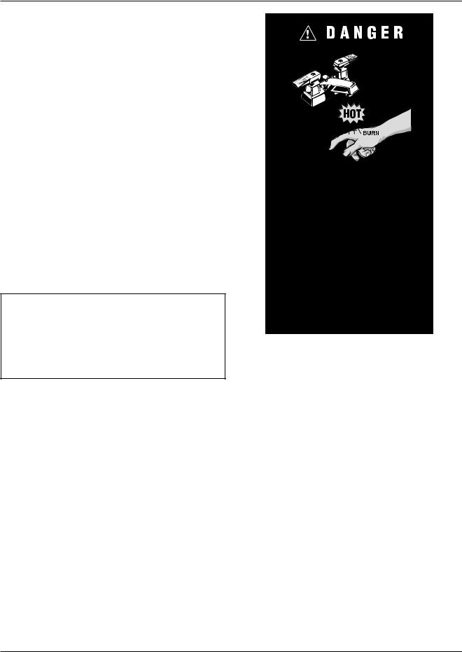
Water temperature over 125°F can cause instant severe burns or death from scalds.
Children, disabled, and elderly are at highest risk of being scalded.
See instruction manual before setting temperature at water heater.
Feel water before bathing or showering.
Temperature limiting valves are available, see manual.
Time/Temperature
Relationships in Scalds
The following chart details the relationship of water temperature and time with regard to scald injury and may be used as a guide in determining the safest water temperature for your applications.
Water |
Time to Produce Serious |
Temp. |
Burn |
|
|
120°F |
More than 5 minutes |
|
|
125°F |
1-1/2 to 2 minutes |
|
|
130°F |
About 30 seconds |
|
|
135°F |
About 10 seconds |
|
|
140°F |
Less than 5 seconds |
|
|
145°F |
Less than 3 seconds |
|
|
150°F |
About 1-1/2 seconds |
|
|
155°F |
About 1 second |
|
|
Table courtesy of The Shriners Burn Institute
Table C: Time to Produce Serious Burn
8
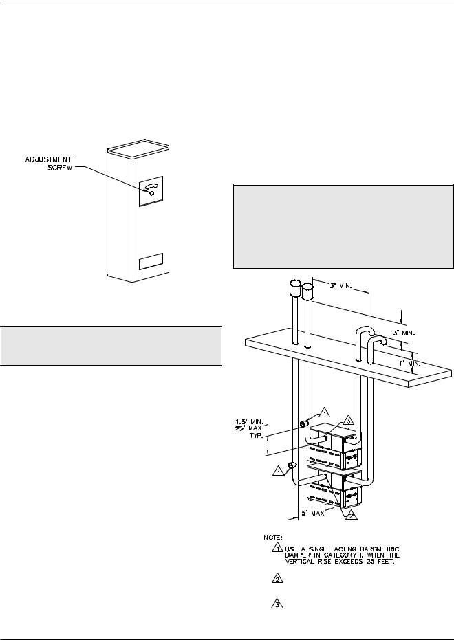
The temperature of the water in the heater can be regulated by using the temperature controller. To comply with safety regulations, the temperature controller is set at the lowest setting when shipped from the factory.
To adjust the water temperature, insert a small straight screwdriver into the adjustment screw on the front of temperature controller and turn the wheel to the desired setting (See Fig. 4.).
Equipment Base
The heater should be mounted on a level, structurally sound surface. The heater is approved for installation on a combustible surface but must NEVER be installed on carpeting. Gas-fueled equipment installed in enclosed parking garages must be located at least 18 in. above the floor.
Stacking
Delta Limited units can be stacked two units high with an optional stacking rack. A stacking kit is available from Raypak for this type of installation.
CAUTION: The heaters should be located in an area where water leakage will not result in damage to the area adjacent to the appliances or to the structure. When such locations cannot be avoided, it is recommended that a suitable catch pan, adequately drained, be installed under the appliance. The pan must not restrict air flow.
Fig. 4: Temperature Control
INSTALLATIONCAUTION: Hotter water increases the risk of scalding! There is a hot water scald potential if the
thermostat is set too high.
INSTALLATION
Installation Codes
Installations must follow these codes:
•Local, state, provincial, and national codes, laws, regulations and ordinances
•National Fuel Gas Code, ANSI Z223.1/NFPA 54 – latest edition (NFGC)
•National Electrical Code, ANSI/NFPA 70 - latest edition (NEC)
•Standard for Controls and Safety Devices for Automatically Fired Boilers, ANSI/ASME CSD-1, when required (CSD-1)
•For Canada only: CAN/CGA B149 Installation Code (B149) and CSA C22.1 C.E.C. Part 1 (C22.1)
REQUIRES OPTIONAL VENT TEE.
REQUIRES OPTIONAL VENT TEE IF VENTED OUT BACK OF HEATER.
Fig. 5: Typical Stacked Installation
9
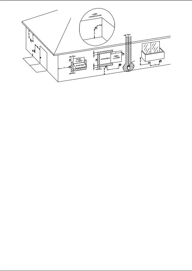
Fig. 6: Minimum Clearances from Vent/Air Inlet Terminations – Indoor and Outdoor Installations
|
|
U.S. Installations1 |
Canadian Installations2 |
|
|
|
|
|
|
A |
Clearance above grade, veranda, porch, |
1 ft (30 cm) |
1 ft (30 cm) |
|
deck, or balcony |
||||
|
|
|
||
|
|
|
|
|
|
Clearance to window or door that may be |
4 ft (1.2m) below or to side |
|
|
B |
of opening; 1 foot (30 cm) |
3 ft (91 cm) |
||
opened |
||||
|
above opening |
|
||
|
|
|
||
|
|
|
|
|
C |
Clearance to permanently closed window |
* |
* |
|
|
|
|
|
|
|
Vertical clearance to ventilated soffit located |
|
|
|
D |
above the terminal within a horizontal dis- |
5 ft (1.5m) |
* |
|
tance of 2 ft (61cm) from the centerline of the |
||||
|
|
|
||
|
terminal |
|
|
|
|
|
|
|
|
E |
Clearance to unventilated soffit |
* |
* |
|
|
|
|
|
|
F |
Clearance to outside corner |
* |
* |
|
|
|
|
|
|
G |
Clearance to inside corner |
6 ft (1.83m) |
* |
|
|
|
|
|
|
|
Clearance to each side of center line ex- |
|
3 ft (91 cm) within a height |
|
H |
* |
15 ft above the me- |
||
tended above meter/regulator assembly |
||||
|
|
ter/regulator assembly |
||
|
|
|
||
|
|
|
|
|
I |
Clearance to service regulator vent outlet |
* |
6 ft (1.83m) |
|
|
|
|
|
|
|
Clearance to non-mechanical air supply inlet |
4 ft (1.2m) below or to side |
|
|
J |
to building or the combustion air inlet to any |
of opening; 1 ft (30 cm) |
3 ft (91 cm) |
|
|
other appliance |
above opening |
|
|
|
|
|
|
|
K |
Clearance to mechanical air supply inlet |
3 ft (91 cm) above if within |
6 ft (1.83m) |
|
10 ft (3m) horizontally |
||||
|
|
|
||
|
|
|
|
|
L |
Clearance above paved sidewalk or paved |
7 ft (2.13m) |
7 ft (2.13m) t |
|
driveway located on public property |
||||
|
|
|
||
|
|
|
|
|
M |
Clearance under veranda, porch, deck or |
* |
12 in. (30 cm) TT |
|
balcony |
||||
|
|
|
||
|
|
|
|
1In accordance with the current ANSI Z223.1/NFPA 54 National Fuel Gas Code
2In accordance with the current CAN/CGA-B149 Installation Codes
t Vent terminal shall not terminate directly above sidewalk or paved driveway located between 2 single family dwellings that serves both dwellings
TT Permitted only if veranda, porch, deck, or balcony is fully open on a minimum of two sides beneath the floor and top of terminal and underside of veranda, porch, deck or balcony is greater than 1 ft (30cm)
*Clearances in accordance with local installation codes and the requirements of the gas supplier
Table D: Vent/Air Inlet Termination Clearances
10
In addition, the heater shall be installed such that the gas ignition system components are protected from water (dripping, spraying, rain, etc.) during appliance operation or service (circulator replacement, control replacement, etc.).
Clearances
Indoor Installations
Heater |
Minimum Clearance |
Recommended |
|
from Combustible |
Service |
||
Side |
|||
Surfaces |
Clearance |
||
|
|||
|
|
|
|
Floor* |
0” |
0” |
|
|
|
|
|
Rear |
1” |
24” |
|
|
|
|
|
Water Side |
12” |
24” |
|
|
|
|
|
Other Side |
1” |
24” |
|
|
|
|
|
Top |
1” |
1” |
|
|
|
|
|
Front |
Open |
24” |
|
|
|
|
|
Vent |
2” |
2” |
|
|
|
|
* DO NOT install on carpeting.
Table E: Clearances – Indoor Installations
TOP VIEW
FRONT VIEW
Venting not shown for clarity. Heater must be vented per instructions in this manual
Fig. 7: Minimum Clearances from Combustible Surfaces – Indoor Installations
When installed according to the listed minimum clearances from combustible construction, these heaters can still be serviced without removing permanent structural construction around the heater. However, for ease of servicing, we recommend a clearance of at least 24 in. in front, and at least 12 in. on the water connection side. This will allow the heater to be serviced in its installed location without movement or removal of the heater.
Service clearances less than the minimums may require removal of the heater to service either the heat exchanger or the burner tray. In either case, the heater must be installed in a manner that will enable the heater to be serviced without removing any structure around the heater.
Outdoor Installations
These heaters are design-certified for outdoor installation. Heaters must not be installed under an overhang that is less than 3 ft from the top of the heater. Three sides must be open in the area under the overhang. Roof water drainage must be diverted away from heaters installed under overhangs.
Heater |
Min. Clearance |
Recommended |
|
from Combustible |
Service |
||
Side |
|||
Surfaces |
Clearance |
||
|
|||
|
|
|
|
Front |
Open |
24” |
|
|
|
|
|
Rear |
12” |
24” |
|
|
|
|
|
Water Side |
36” |
36” |
|
|
|
|
|
Other Side |
36” |
36” |
|
|
|
|
|
Top |
Unobstructed |
36” |
|
|
|
|
|
Vent |
N/A |
N/A |
|
|
|
|
Table F: Clearances – Outdoor Installations
These clearances are required when the outdoor vent cap is used. If installing the heater outdoors with a vent stack, the indoor clearances may be utilized.
The combustion air intake hood MUST be used for outdoor installations. The hood is shipped loose and installed on the side of the heater over the filter box at the jobsite.
11
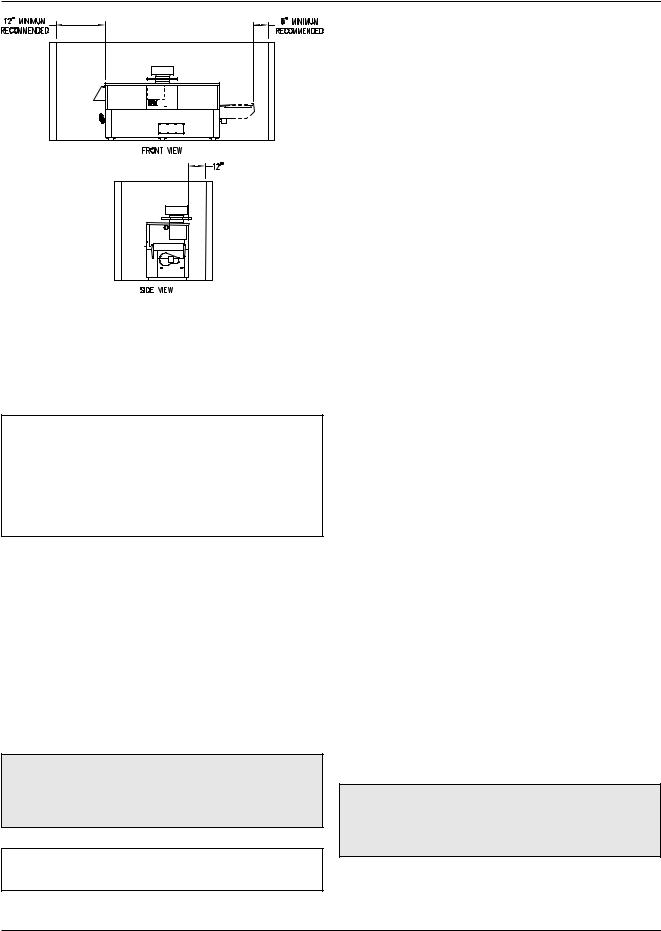
Fig. 8: Minimum Clearances from Combustible Surfaces – Outdoor Installations
Combustion and Ventilation Air
NOTE: Use of the heater in construction areas where fine particulate matter, such as concrete or dry-wall dust, is present may result in damage to the heater that is not covered by the warranty. If operated in a construction environment, a clean source of combustion air must be provided directly to the heater.
Indoor Units
The heater must be supplied with sufficient quantities of non-contaminated air to support proper combustion and equipment ventilation. Combustion air can be supplied via conventional means where combustion air is drawn from the area immediately surrounding the heater, or via direct vent, where combustion air is drawn directly from outside. All installations must comply with the requirements of the NFGC (U.S.) and B149 (Canada), and all local codes.
CAUTION: Combustion air must not be contaminated by corrosive chemical fumes which can damage the heater and void the warranty. (See the Appendix.)
NOTE: It is recommended that the intake vent be insulated to minimize sweating.
Reversing Air Filter
Follow these instructions to change the air duct connection from the left-hand side (standard) to the right-hand side:
1.Remove the four screws and the dust cover from the right-hand side of the heater.
2.Remove the four screws and the air filter bracket from the left-hand side of the heater.
3.Reverse the components and reattach in the new location, making sure that the air filter locking bracket is on the bottom. (The air filter locking bracket is reversible.)
Direct-Ducted Combustion Air
In certain applications it may be desirable to duct the combustion air directly to the heater. This should be done with PVC, CPVC or single-wall galvanized ducting. The duct will attach directly to the collar on the air filter housing located on the side of the heater. The ducting is attached to the air filter housing collar using three or four sheet metal screws (not supplied) equally distributed around the circumference of the duct. All ducting should be self-supported. The filter housing is not designed to support the air duct.
Conventional Combustion Air
Supply
U.S. Installations
All Air from Inside the Building
The confined space shall be provided with TWO permanent openings communicating directly with an additional room(s) of sufficient volume so that the combined volume of all spaces meets the criteria for a room large in comparison (NFGC). The total input of all gas utilization equipment installed in the combined
CAUTION: This type of installation is recommended if damaging airborne contaminants are or will be present in the heater area. See the Appendix regarding air contamination.
12
space shall be considered in making this determination. Each opening shall have a minimum free area of 1 in.2 per 1,000 BTUH (2,225 mm2 per kW) of the total input rating of all gas utilization equipment in the confined space, but not less than 100 in.2 (645 cm2). One opening shall commence within 12 in. (305 mm) of the top, and one opening shall commence within 12 in. (305 mm) of the bottom of the enclosure. The minimum dimension of air openings shall be not less than 3 in. (76 mm) in any direction.
All Air from Outdoors
The confined space shall communicate with the outdoors in accordance with one of the methods below. The minimum dimension of air openings shall not be less than 3 in. (76 mm) in any direction. Where ducts are used, they shall be of the same cross-sectional area as the net free area of the openings to which they connect.
1.Two permanent openings, one commencing within 12 in. (305 mm) of the top, and one commencing within 12 in. (305 mm) of the bottom of the enclosure, shall be provided. The openings shall communicate directly, or by ducts, with the outdoors or spaces (crawl or attic) that freely communicate with the outdoors.
a.Where directly communicating with the outdoors or where communicating to the outdoors through vertical ducts, each opening shall have a minimum free area of 1 in.2 per 4,000 BTUH (550 mm2 per kW) of total input rating of all equipment in the enclosure.
b.Where communicating with the outdoors through horizontal ducts, each opening shall have a minimum free area of 1 in.2 per 2,000 BTUH (1,100 mm2 per kW) of total input rating of all equipment in the enclosure.
2.One permanent opening, commencing within 12 in. (305 mm) of the top of the enclosure, shall be permitted where the equipment has clearances of at least 1 in. (25 mm) from the sides and back and 6 in. (152 mm) from the front of the appliance. The opening shall directly communicate with the outdoors or shall communicate through a vertical or horizontal duct to the outdoors or spaces that freely communicate with the outdoors, and shall have a minimum free area of:
a.1 in.2 per 3,000 BTUH (740 mm2 per kW) of the total input rating of all equipment located in the enclosure, and
b.Not less than the sum of the areas of all vent connectors in the confined space.
WARNING: Do not use one permanent opening method if the equipment room is under negative pressure conditions or the equipment is common vented with other gas-fired appliances.
Canadian Installations
CAUTION: All combustion air must be drawn from the air outside of the building; the mechanical equipment room must communicate directly with the outdoors.
1.Ventilation of the space occupied by the heater shall be provided by an opening(s) for ventilation air at the highest practical point communicating with the outdoors. The total cross-sectional area of such an opening(s) shall be at least 10% of the area required in 2. and 3. (below), but in no case shall the cross-sectional area be less than 10 in.2
(65 cm2).
2.For heaters using a barometric damper in the vent system there shall be a permanent air supply opening(s) having a cross section area of not less than 1 in.2 per 7,000 BTUH (320 mm2 per kW) up to and including 1 million BTUH, plus 1 in.2 per 14,000 BTUH (160 mm2 per kW) in excess of 1 million BTUH. This opening(s) shall be either located at or ducted to a point not more than 18 in. (450 mm) nor less than 6 in. (152 mm) above the floor level. The duct can also “goose neck” through the roof. The duct is preferred to be straight down and terminated 18 in. (450 mm) from the floor, but not near piping. This air supply opening requirement shall be in addition to the air opening for ventilation air required in 1. (above).
WARNING: Care must be taken to ensure that the equipment room is not under negative pressure conditions or that the equipment is not commonvented with other gas-fired appliances.
3.For heaters not using a barometric damper in the vent system, and when air supply is provided by natural air flow from outdoors for a power burner and there is no draft regulator, drafthood or similar flue gas dilution device installed in the same space, in addition to the opening for ventilation air required in 1., there shall be a permanent air supply opening(s) having a total cross-sectional area
13
of not less than 1 in.2 for each 30,000 BTUH mm2 per kW) of total rated input of the burner(s), and the location of the opening(s) shall not interfere with the intended purpose of the opening(s) for ventilation air referred to in (1). This opening(s) can be ducted to a point not more than 18 in. (450 mm) nor less than 6 in. (152 mm) above the floor level. The duct can also “goose neck” through the roof. The duct is preferred to be straight down 18 in. (450 mm) from the floor, but not near piping.
4.Refer to B149 Installation code for additional information.
Water Piping
General
The heater should be located so that any water leaks will not cause damage to the adjacent area or structures.
CAUTION: This heater requires forced water circulation when the burner is operating. See Table G and Table H for minimum and maximum flow rates and water pump selection. The pump must be interlocked with the heater to prevent heater operation without water circulation.
NOTE: Minimum pipe size for in/out connections is 2 1⁄2 in (2 in. for 399B–899B). Verify proper flow rates and ΔT as instructed in this manual.
5.Remove all plumbing fittings to the header. This will include both inlet and outlet water pipe unions and the pressure relief valve and drain piping.
6.Remove limits, control bulbs and/or thermocouples.
7.Remove the six (or 8) flange nuts and the in/out header from the left-hand side.
8.Remove the six (or 8) flange nuts and the return header from the right-hand side.
9.Remove the header stud bolts from each tube sheet.
10.Reverse the headers and stud bolts to the new location.
11.Install NEW red beveled O-rings flush against both tube sheets with the bevel facing outward.
12.Push the header firmly against the O-rings. Install and tighten the flange nuts onto the stud bolts until finger tight.
13.Slowly tighten the flange nuts, starting from the center nut (number 1) in Fig. 9 and working sequentially around the header as indicated. Torque all nuts to 25 ft/lb. DO NOT OVER-TIGHTEN.
14.Re-route the capillary(s), wiring etc. to the new location, adding thermal paste and shim to the capillary well.
Reversing Water Connections |
Relief Valve Piping |
Follow these instructions to change the water connections from the left-hand side (standard) to the right-hand side.
1.Disconnect all electrical power from the heater (if applicable).
2.Label all electrical connections and conduit lines. This may include the flow switch, low water cut-off probe and/or pump.
3.Disconnect or isolate the main gas pipe from the heater (if applicable).
4.Remove both in/out and return header access panels by removing all sheet metal screws.
WARNING: Pressure relief valve discharge piping must be piped near the floor and close to a drain to eliminate the potential of severe burns. Do not pipe to any area where freezing could occur. Refer to local codes.
Hydrostatic Test
Unlike many types of heaters, this heater does not require hydrostatic testing prior to being placed in operation. The heat exchanger has already been fac- tory-tested and is rated for 160 psi operating pressure. However, Raypak does recommend hydrostatic testing of the piping connections to the heater and the rest of the system prior to operation. This is particularly true for hydronic systems using expensive glycolbased anti-freeze. Raypak recommends conducting
14
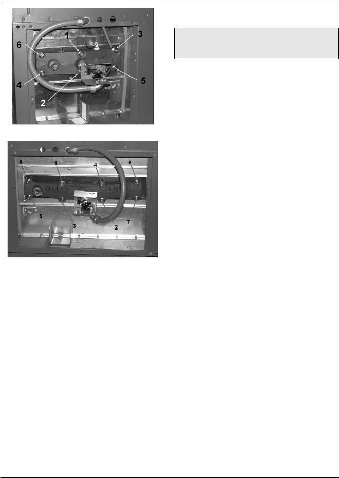
Models 399B–899B
Models 989B–2339B
Fig. 9: Torque Sequence
the hydrostatic test before connecting gas piping or electrical supply.
Leaks must be repaired at once to prevent damage to the heater. NEVER use petroleum-based stop-leak compounds.
To perform hydrostatic test:
1.Connect fill water supply. With bleed valve open, fill heater with water. When water flows from bleed valve, shut off water. Close bleed valve. Carefully fill the rest of the system, making sure to eliminate any entrapped air by using high-point vents. Close feed valve. Test at standard operating pressure for at least 24 hours.
2.Make sure constant gauge pressure has been maintained throughout test.
3.Check for leaks. Repair if found.
Cold Water Operation
CAUTION: Damaging internal condensation may occur if the heater inlet water temperature does not exceed 105ºF (41ºC) within 7 minutes of start-up.
A heater operated with an inlet temperature of less than 105ºF (41ºC) must have a manual bypass or an approved low-temperature operation system to prevent problems with condensation. A manual bypass, shown in Fig. 15, must be piped into the system at the time of installation. This piping is like a primary/secondary boiler installation with a bypass acting as the secondary boiler piping. Raypak strongly recommends that thermometer(s) be placed into the heater piping next to the in/out header to facilitate temperature adjustment. Inlet water temperatures below
105ºF (41ºC) can excessively cool the products of combustion, resulting in condensation on the heat exchanger and in the flue.
Failure to exceed 105ºF (41ºC) within 7 minutes may result in the premature failure of the hot surface igniter, remote flame sensor, burners and heat exchanger. It can cause operational problems, bad combustion, sooting, flue gas spillage and reduced service life of the vent system. The bypass allows part of the heater discharge water to be mixed with the cooler heater return water to increase the heater inlet temperature above 105ºF (41ºC). This precautionary measure should prevent the products of combustion from condensing in most installations. Warranty claims will be denied when condensation occurs.
Cold water operation issues are applicable to both cold water start and cold water run applications. Cold water operation for 7 minutes or less on start-up is acceptable. Where cold water starts will last longer than 7 minutes or where cold water operation is continuous, provisions must be made to mix higher temperature outlet water with the colder inlet water and thereby raise the inlet temperature to at least 105ºF (41ºC) within the 7-minute time limit.
Cold Water Starts
Frequent (more than once a week) cold water starts, wherein the inlet water temperature remains below 105ºF (41ºC) for more than 7 minutes, must have cold water start protection. Known protection methods consist of mixing heated outlet water with the inlet water with a bypass to raise the inlet to 105ºF (41ºC) or higher. Once the system is heated up and has return water temperatures of 105ºF (41ºC) or higher, the mixing of outlet water with inlet water is no longer needed and the bypass can be shut off. If the bypass is not shut off
15

as the system heats up, the outlet temperature may continue to climb and actuate the high limit, thereby shutting down the heater. Thus an automatic valve system, such as a three-way proportional valve or a modulating two-way valve to control the bypass, should be utilized.
Cold Water Run
Cold water run differs from cold water start in that the system water entering the heater remains below 105ºF (41ºC) continuously. Typically, this is the case in swimming pool heating and water source heat pump applications as well as some others. If the system water is kept in a narrow temperature range, a permanent manual bypass can be employed and manually adjusted to achieve an inlet temperature of 105ºF (41ºC) or higher. An injector pump arrangement may also be utilized to keep the heater loop at or above
105ºF (41ºC). An injector pump approach has the added value of being able to adjust to changes in the system water coming back to the heater take-off.
Temperature & Pressure Gauge
The temperature and pressure gauge is factorymounted in the in/out header.
Hydronic Heating
Pump Selection
In order to ensure proper performance of your heater system, you must install a correctly sized pump. Raypak recommends using a 20°F ΔT as design ΔT. (ΔT is the temperature difference between the inlet and outlet water when the heater is firing at full rate). If a ΔT of larger than 20°F is necessary, see Table G and Table H for flow rate requirements.
Model |
10°F ΔT |
20°F ΔT |
30°F ΔT |
|
Min. Flow |
|
Max. Flow |
|
|||||||
|
|
|
|
|
|
|
|
|
|
|
|
|
|
|
|
No. |
gpm |
ΔP (ft) |
gpm |
ΔP (ft) |
gpm |
ΔP (ft) |
gpm |
|
ΔP (ft) |
|
ΔT |
gpm |
ΔP (ft) |
|
ΔT |
|
|
|
|
||||||||||||
|
|
|
|
|
|
|
|
|
|
|
|
|
|
|
|
399B |
67 |
5.5 |
34 |
1.4 |
22 |
0.6 |
20 |
|
0.5 |
|
34 |
90 |
10.0 |
|
7 |
|
|
|
|
|
|
|
|
|
|
|
|
|
|
|
|
499B |
84 |
9.1 |
42 |
2.3 |
28 |
1.1 |
21 |
|
0.6 |
|
40 |
90 |
10.4 |
|
9 |
|
|
|
|
|
|
|
|
|
|
|
|
|
|
|
|
649B |
|
|
55 |
4.1 |
36 |
1.8 |
27 |
|
1.1 |
|
40 |
90 |
10.8 |
|
12 |
|
|
|
|
|
|
|
|
|
|
|
|
|
|
|
|
749B |
|
|
63 |
5.7 |
42 |
2.6 |
32 |
|
1.5 |
|
40 |
90 |
11.3 |
|
14 |
|
|
|
|
|
|
|
|
|
|
|
|
|
|
|
|
899B |
|
|
76 |
8.3 |
50 |
3.8 |
38 |
|
2.2 |
|
40 |
90 |
11.7 |
|
17 |
|
|
|
|
|
|
|
|
|
|
|
|
|
|
|
|
989B |
|
|
83 |
5.2 |
55 |
2.3 |
42 |
|
1.3 |
|
40 |
132 |
13.1 |
|
13 |
|
|
|
|
|
|
|
|
|
|
|
|
|
|
|
|
1259B |
|
|
106 |
9.6 |
71 |
4.3 |
53 |
|
2.4 |
|
40 |
132 |
14.8 |
|
16 |
|
|
|
|
|
|
|
|
|
|
|
|
|
|
|
|
1529B |
|
|
129 |
15.7 |
86 |
7.1 |
64 |
|
4.0 |
|
40 |
132 |
16.5 |
|
19 |
|
|
|
|
|
|
|
|
|
|
|
|
|
|
|
|
1799B |
|
|
|
|
101 |
10.7 |
76 |
|
6.0 |
|
40 |
132 |
18.3 |
|
23 |
|
|
|
|
|
|
|
|
|
|
|
|
|
|
|
|
1999B |
|
|
|
|
112 |
13.8 |
84 |
|
7.9 |
|
40 |
132 |
19.0 |
|
25 |
|
|
|
|
|
|
|
|
|
|
|
|
|
|
|
|
2069B |
|
|
|
|
116 |
14.8 |
87 |
|
8.5 |
|
40 |
132 |
19.0 |
|
26 |
|
|
|
|
|
|
|
|
|
|
|
|
|
|
|
|
2339B |
|
|
|
|
132 |
21.4 |
98 |
|
12.1 |
|
40 |
132 |
21.4 |
|
30 |
|
|
|
|
|
|
|
|
|
|
|
|
|
|
|
|
Notes: 1. Basis for minimum flow: Models 399–899, 20 gpm or 40°F ΔT. Models 989–2339, 30 gpm or 40°F ΔT. Basis for maximum flow: Models 399–899, 90 gpm. Models 989–2339, 132 gpm.
2. Flow switch will not operate if flow is less than 20 gpm.
Table G: Heater Rates of Flow and Pressure Drops
16
 Loading...