


 Loading...
INSTALLATION & OPERATING
INSTRUCTIONS
Raytherm®
Hot Water
Supply
Heaters
Models 0133–4001
Type WH
 ® LLC
® LLC
WARNING: Improper installation, adjustment, alteration, service or maintenance can |
|||
cause property damage, personal injury or loss of life. Refer to this manual. |
|||
Installation and service must be performed by a qualified installer, service agency or |
|||
the gas supplier. |
|
|
|
FOR YOUR SAFETY: Do not store or use gasoline or other flammable vapors and |
|||
liquids or other combustible materials in the vicinity of this or any other appliance. To |
|||
do so may result in an explosion or fire. |
|
|
|
WHAT TO DO IF YOU SMELL GAS: |
|
|
|
• Do not try to light any appliance. |
|
|
|
• Do not touch any electrical switch; do not use any phone in your building. |
|||
• Immediately call your gas supplier from a neighbor's phone. Follow the gas |
|||
supplier's instructions. |
|
|
|
• If you cannot reach your gas supplier, call the fire department. |
|
||
Installation and service must be performed by a qualified installer, service agency or |
|||
the gas supplier. |
|
|
|
This manual should be maintained in legible condition and kept adjacent to the heater or in a safe place for future |
|||
reference. |
|
|
|
CATALOG NO. 3000.52Q |
Effective: 09-01-15 |
Replaces: 04-20-12 |
P/N 241075 Rev. 18 |
Rev. 16 reflects the following:
Changes to: ASME Mark on page 1, warnings on page 4, warning on page 27
Additions: Warnings on page 7, warning on page 13, warnings on page 14, warning on page 19, caution on page 20, warning on page 30, warning on page 48
2

|
|
|||
CONTENTS |
|
|||
WARNINGS |
|
4 |
Burner Adjustment |
34 |
Pay Attention to These Terms |
|
4 |
Visual Inspection |
34 |
GENERAL SAFETY |
|
5 |
Electrical |
34 |
Time/Temperature Relationships in Scalds 6 |
High Gas Pressure Switch |
34 |
||
RECEIVING EQUIPMENT |
|
6 |
Burner Tray Removal |
34 |
Model Identification |
|
6 |
Gas Valve Removal |
34 |
General Specifications |
|
7 |
Main Burner And Orifice Removal |
35 |
All Models (Approved) |
|
7 |
Pilot Removal |
35 |
Hot Water Supply Heaters |
|
7 |
Combustion Fan Removal |
35 |
INSTALLATION |
|
7 |
TROUBLESHOOTING |
36 |
Installation Codes |
|
7 |
Electrical |
36 |
Installation Base |
|
7 |
Mechanical |
37 |
Clearances |
|
8 |
WIRING DIAGRAMS |
38 |
Specifications and Dimensions |
|
9 |
Wiring Diagram—W2/WH2 133 |
38 |
Outdoor Water Heaters |
|
12 |
Wiring Diagram—WH1 0181/0261 |
39 |
Combustion Air (Indoor Units Only) Air for |
|
Wiring Diagram—WH1 0331/0401 |
40 |
|
Combustion and Ventilation |
|
12 |
Wiring Diagram—WH1 0514–0724 |
41 |
Venting |
|
13 |
Wiring Diagram—WH1 0824–1826 |
42 |
Vent Piping |
|
17 |
Wiring Diagram—WH1 2100–2500 |
43 |
Vent Damper Installation |
|
18 |
Wiring Diagram—WH1 3001–4001 |
44 |
Plumbing |
|
20 |
Troubleshooting—Pumps |
45 |
Flow Rates |
|
22 |
SERVICE AND MAINTENANCE |
|
Piping—Domestic Hot Water Supply |
|
|
PROCEDURES |
45 |
Heaters |
|
23 |
Tube Cleaning |
45 |
Piping Diagram—Type WH - Unitemp 80 |
|
|
Burner Tray Removal |
46 |
System |
|
24 |
Gas Valve Removal |
46 |
Controls—General |
|
25 |
Gas Valve Adjustment - Robertshaw |
|
Limit Controls |
|
26 |
(Invensys) 7000 Series 2-Stage Gas Valve |
|
Electrical Connections |
|
27 |
with Solenoid Valve |
46 |
Location of Controls |
|
28 |
Main Burner and Orifice Removal |
47 |
START-UP PROCEDURES |
30 |
Pilot Removal and Cleaning |
47 |
|
Before Start-Up |
|
30 |
High Limit or Tankstat Removal |
47 |
General |
|
30 |
Heat Exchanger Removal |
47 |
Initial Start-Up - Pump and Motor |
|
30 |
Heat Exchanger Re-Assembly |
47 |
Intermittent Pilot System Checkout |
|
|
Combustion Chamber Removal |
48 |
Procedure (S8600) |
|
32 |
Control Well Replacement |
48 |
INSPECTION PROCEDURES |
32 |
Tube Replacement |
48 |
|
Burners |
|
32 |
Cleaning Flue Gas Passageways |
49 |
Controls |
|
32 |
REPLACEMENT PARTS |
49 |
Inspection Procedures |
|
33 |
WARRANTY |
50 |
ADDENDA: LOW NOx HEATERS |
|
|
|
|
Models 0181 to 0401 |
33 |
|
|
|
Operation |
|
33 |
|
|
Start-Up Procedures |
|
|
|
|
(S8610B Ignition Module) |
|
33 |
|
|
3

WARNINGS—Pay Attention to These Terms
Indicates the presence of immediate hazards which will cause severe personal injury, death or substantial property damage if ignored.
Indicates the presence of hazards or unsafe practices which could cause severe personal injury, death or substantial property damage if ignored. Indicates the presence of hazards or unsafe practices which could cause minor personal injury or product or property damage if ignored.
Indicates special instructions on installation, operation, or maintenance which are important but not related to personal injury hazards.
DANGER: Failure to install the draft hood and properly vent the water heater to the outdoors as outlined in the Venting section of this manual can result in unsafe operation of the water heater. To avoid the risk of fire, explosion, or asphyxiation from carbon monoxide, never operate this water heater unless it is properly vented and has an adequate air supply for proper operation. Be sure to inspect the vent system for proper installation at initial start-up; and at least annually thereafter. Refer to the Maintenance section of this manual for more information regarding vent system inspections.
DANGER: Make sure the gas on which the heater will operate is the same type as that specified on the heater rating plate.
DANGER: When servicing or replacing components that are in direct contact with the water, be certain that:
• There is no pressure in the heater. (Pull the release on the relief valve. Do not depend on the pressure gauge reading).
• The heater water is not hot.
• The electrical power is off.
WARNING: Risk of electrical shock. More than one disconnect switch may be required to de-energize the equipment before servicing.
WARNING: All venting types must be of the same material or product throughout the entire exhaust installation to ensure proper securing and sealing.
WARNING: Should overheating occur or the gas supply valve fail to shut, do not turn off or disconnect the electrical supply to the heater. Instead, shut off the gas supply at a location external to the heater.
WARNING: Both propane and natural gas have an odorant added to help detection. Some people may not physically be able to smell or recognize this odorant. If unsure or unfamiliar about the smell associated with propane or natural gas, ask the gas supplier. Other conditions, such as "Odorant Fade", which causes the odorant to "fade", or diminish in intensity can also hide or camouflage a gas leak.
WARNING: UL recognized fuel gas detectors are recommended in all enclosed propane and natural gas applications wherein there is a potential for an explosive mixture of fuel gas to accumulate and their installation should be in accordance with the detector manufacturer's recommendations and/or local laws, rules, regulations, or customs.
WARNING: Do not use this heater if any part has been under water. Immediately call a qualified service technician to inspect the heater and to replace any part of the control system and any gas control which has been under water.
WARNING: Altering any Raypak pressure vessel by installing replacement heat exchangers, tube bundle headers, or any ASME parts not manufactured and/or approved by Raypak will instantly void the ASME and/or CSA ratings of the vessel and any Raypak warranty on the vessel. Altering the ASME and/or CSA ratings of the vessel also violates national, state, and local approval codes.
WARNING: Propane appliances should not be installed below-grade (for example, in a basement) if such installation is prohibited by federal, state and/or local laws, rules, regulations or customs.
4
WARNING - CALIFORNIA PROPOSITION 65: This product contains chemicals known to the State of California to cause cancer, birth defects or other reproductive harm.
! DANGER
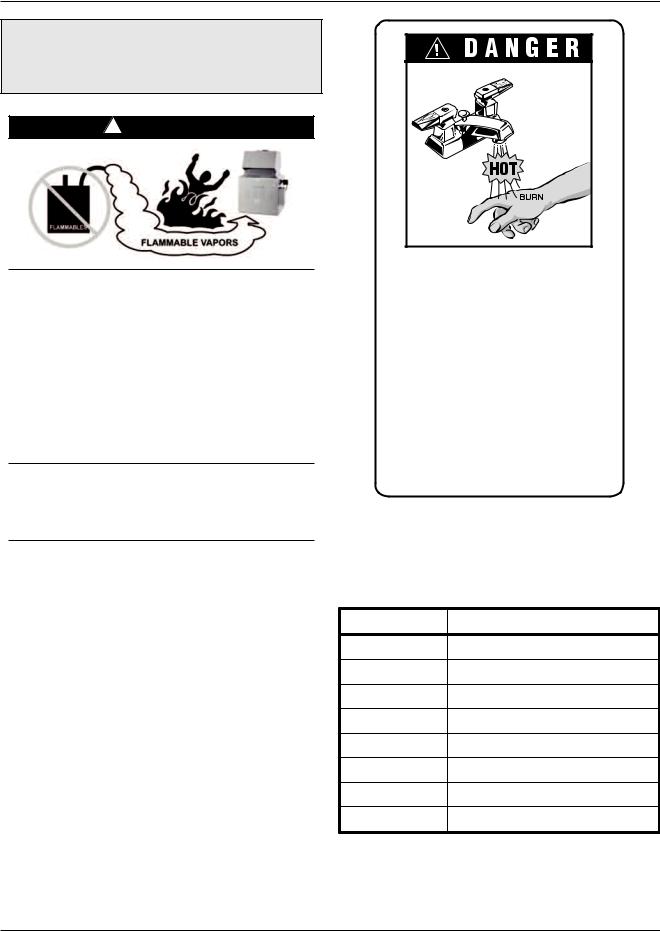
Vapors from flammable liquids will explode and catch fire causing death or severe burns.
Do not use or store flammable products such as gasoline solvents or adhesives in the same room or area near the water heater.
Keep flammable products:
1.Far away from heater,
2.In approved containers,
3.Tightly closed and
4.Out of children's reach.
Water heater has a main burner and pilot flame.
The pilot flame:
1.Is on all the time or intermittently (IID).
2.Will ignite flammable vapors.
Vapors:
1.Cannot be seen,
2.Are heavier than air,
3.Go a long way on the floor,
4.Can be carried from other rooms to the pilot flame by air currents.
Installation:
Do not install water heater where flammable products will be stored or used unless the main burner and pilot flames are at least 18" above the floor. This will reduce, but not eliminate, the
risk of vapors being ignited by the main burner or pilot flame.
GENERALRead and follow water heaterSAFETYwarnings and instructions.
To meet commercial hot water needs, this heater is equipped with a manual reset temperature limit that does not exceed 200°F. However, water temperatures over 125°F can cause instant severe burns or death from scalds. This is the preferred temperature setting when supplying general purpose hot water.
Safety and energy conservation are factors to be considered when setting the water temperature on the thermostat. The most energy-efficient operation will result when the temperature setting is the lowest that satisfies the needs consistent with the application.
Maximum water temperatures occur just after burner has shut-off. To determine the water temperature being delivered, turn on the hot water only, place a thermometer in the stream, and read the thermometer.
Water temperature over 125°F can cause instant severe burns or death from scalds.
Children, disabled, and elderly are at highest risk of being scalded.
See instruction manual before setting temperature at water heater.
Feel water before bathing or showering.
Temperature limiting valves are available, see manual.
The following chart details the relationship of water temperature and time with regard to scald injury and may be used as a guide in determining the safest water temperature for your applications.
Temperature |
Time to Produce Serious Burn |
120°F |
More than 5 minutes |
125°F |
1-1/2 to 2 minutes |
130°F |
About 30 seconds |
135°F |
About 10 seconds |
140°F |
Less than 5 seconds |
145°F |
Less than 3 seconds |
150°F |
About 1-1/2 seconds |
155°F |
About 1 second |
Table courtesy of Shriners Burn Institute.
Table A: Time to Produce Serious Burn
5
Time/Temperature Relationships in Scalds
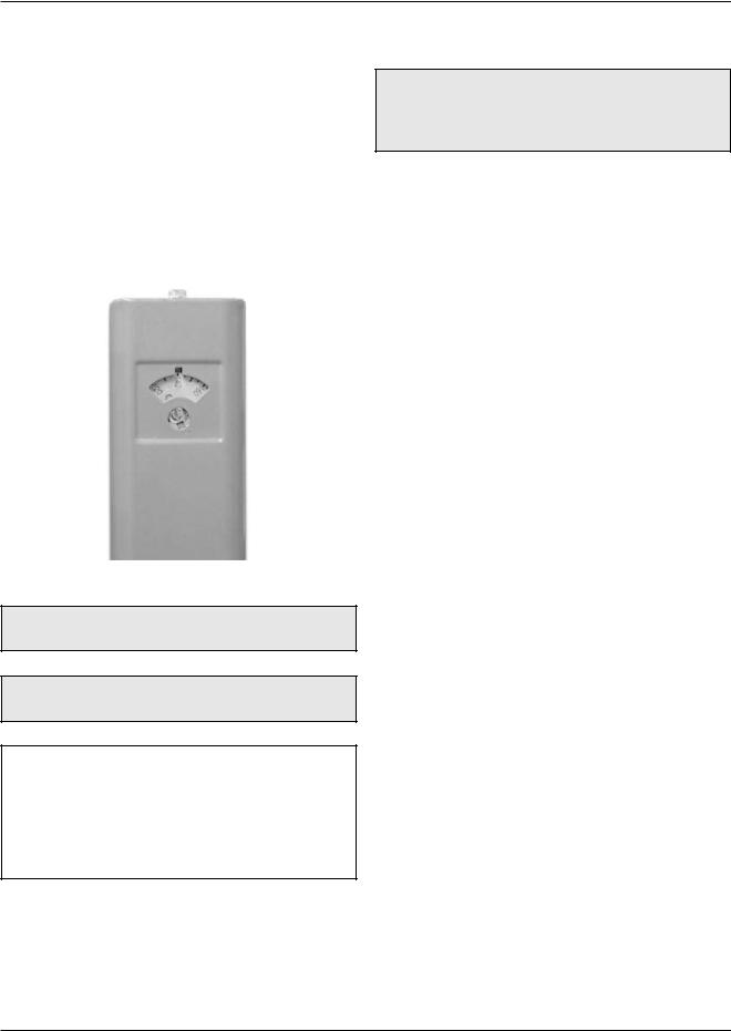
The temperature of the water in the storage tank heater can be regulated by setting the temperature dial on front of the tankstat. To comply with safety regulations, the tankstat was set at its lowest setting before shipment from the factory.
Fig. 1 illustrates a mechanical tankstat. To adjust the water temperature, insert a small straight screwdriver into slotted screw in hole in front of tankstat and turn wheel to desired setting. Thermostat is adjustable up to 190°F.
Fig. 1: Tankstat Adjustment
DANGER: There is a Hot Water SCALD Potential if the tankstat is set too high.
CAUTION: Hotter water increases the risk of SCALDING!
NOTE: When this heater is supplying general purpose hot water requirements for use by individuals, a thermostatically controlled mixing valve for reducing point of use water temperature is recommended to reduce the risk of scald injury. Contact a licensed plumber or the local plumbing authority for further information.
RECEIVING EQUIPMENT
WARNING: Pump motors should NOT be supported by any type of stand or support from above due to possible misalignment of pump and motor which might occur.
On receipt of the equipment, visually check for external damage to the carton or the shipping crate. If the carton or shipping crate is damaged, make a note on the Bill of Lading and report the damage to the Carrier immediately. Remove the heater from the carton or the shipping crate.
Do NOT use the shipping crate base as an installation base. On occasion, items are shipped loose. Be sure that you receive the number of packages indicated on the Bill of Lading.
When ordering parts, you must specify Model and Serial Number of the heater. When ordering under warranty conditions, you must also specify date of installation.
Raypak recommends that this manual be reviewed thoroughly before installing your Raypak heater. If there are any questions which this manual does not answer, please contact the factory or your local Raypak representative.
Claims for shortages and damages must be filed with carrier by consignee. Permission to return goods must be factory-authorized and are subject to a stocking charge.
Purchased parts are subject to replacement only under the manufacturer's warranty. Debits for defective replacement parts will not be accepted and will be replaced in kind only per our standard warranties.
Model Identification
The model identification number and the heater serial number are found on the heater data plate. The model number will have the form WH1-0514A or similar depending on the heater model. (WH = Hot Water Supply System, 1 = on/off firing, 0514 = size of heater).
Rated inputs are suitable for up to 2000 feet elevation. For elevations above 2000 feet, reduce input 4% for each 1000 feet above sea level.
6

General Specifications
The Raypak water heaters are design certified and tested under the latest requirements of the American National Standard, ANSI Z21.10.3/CSA 4.3. Each heater has been constructed and pressure tested in accordance with the requirements of Section IV of the American Society of Mechanical Engineers Code, and factory fire tested. Materials are CSA-certified for lowlead content (<.25%).
All Models (Approved)
All models are National Board approved. Temperature and pressure gauge is standard. Intermittent ignition device is standard on models 0514 and up.
Model 0133 has 4-pass heat exchanger, 1 tube per pass.
Models 0181-0401 have 2-pass heat exchangers, 5 tubes first pass, 4 tubes second pass.
Models 0514-1826 have 2-pass heat exchangers, 5 tubes first pass, 4 tubes second pass.
Models 2100-4001 have 2-pass heat exchangers, 9 tubes per pass.
Models 0926-4001 have optional single pass with cast iron headers only.
Hot Water Supply Heaters
All Raypak hot water supply heaters are ASME rated and design certified as hot water heaters, with 125 PSI pressure relief valves.
TYPE WH1 with ON/OFF CONTROLS Models 0133-4001
To be used with storage tank systems. Available with integrally mounted pump, factory mounted and wired for models 0133-1826. Models 0181, 0261, 0331 and 0401 are Low NOx Hot Water Heaters.
TYPE WH2 with MODULATING CONTROLS
Models 0133-4001
Hot water supply heater with 110°-170°F gas modulation. Available with integrally mounted pump, factory mounted and wired for models 0133-1826. To be used with storage tank systems.
7
TYPE WH3 with 2-STAGE
CONTROLS
Models 0181-4001
Hot water supply heater with low-high fire for 2-stage control. Available with integrally mounted pump, factory mounted and wired for models 0181-1826. To be used with storage tank systems.
INSTALLATION
Installation Codes
Installation must be in accordance with local codes, or, in the absence of local codes, with the latest editions of the National Fuel Gas Code, ANSI Z223.1/NFPA 54, and the National Electrical Code, ANSI/NFPA 70. In Canada installations must conform with the current CAN/CSA B149 and the Canadian Electrical Code Part 1 CSA C22.2 No.1. Where required by the authority having jurisdiction, the installation must conform to American Society of Mechanical Engineers Safety Code for Controls and Safety Devices for Automatically Fired Heaters, CSD-1.
WARNING: This product must be installed by a licensed plumber or gas fitter when installed within the Commonweatlh of Massachusetts.
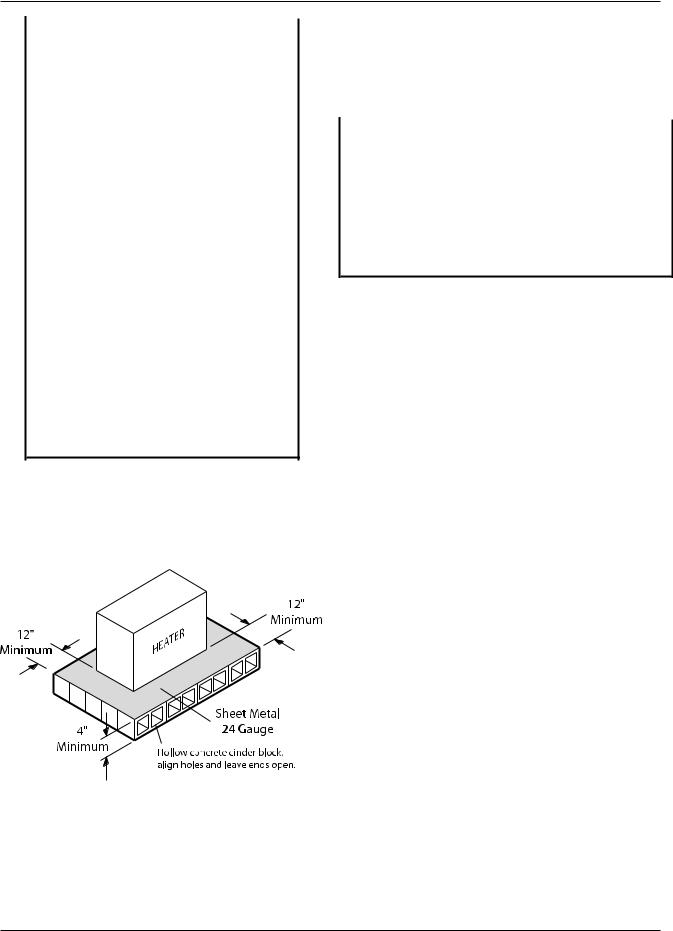
Installation Base
The heater should be mounted on a level, non-com- bustible surface. Heater must not be installed on carpeting. The heater can be installed on a combustible surface only when the appropriate listed floor shield base is provided. An optional listed floor shield base is available for factory installation with the heater on all indoor models. Do NOT use the shipping base crate as an installation base.
NOTE: The heater should be located in an area where water leakage will not result in damage to the area adjacent to the appliance or to the structure. When such locations cannot be avoided, it is recommended that a suitable drain pan, adequately drained, be installed under the appliance. The pan must not restrict air flow.
WARNING: The heater shall not be located in an area where water sprinklers, or other devices, may cause water to spray through the cabinet louvers and into the heater. This could cause internal rusting or damage electrical components, and void the warranty.
Heater |
Floor Base |
Model |
Part |
Number |
Number |
0133 |
001749 |
0182/0181 |
058313 |
0260/0261 |
058314 |
0330/0331 |
058315 |
0400/0401 |
058316 |
0514 |
056199 |
0624 |
056200 |
0724 |
056201 |
0824 |
056202 |
0926* |
054597 |
1083* |
054598 |
1178* |
054599 |
1287* |
054600 |
1414* |
054601 |
1571* |
058378 |
1758* |
058379 |
0962 |
059233 |
1125 |
059234 |
1223 |
059235 |
1336 |
059236 |
1468 |
059237 |
1631 |
059238 |
1826 |
059239 |
*Models with factory installed floor shield as standard.
BOLD TYPE indicates Low NOx models.
Table B: Combustible Floorshield Ordering Information
Fig. 2: Alternate Method for Providing a NonCombustible Base
Clearances
Installation Clearances
(All Dimensions are in Inches)
|
|
|
Heater Size |
|
|
|
||
|
0133 |
0181 to |
|
0514 to |
|
0926 to |
2100 to |
|
Location |
|
0401 |
|
0824 |
|
1826 |
4001 |
|
Floor |
|
|
See Note 1 |
|
|
|
||
Front |
|
|
See Note 2 |
|
|
|
||
Back |
12 |
12 |
|
12 |
|
24 |
24 |
|
Right |
6 |
12 |
|
6 |
|
24 |
24 |
|
Left |
12 |
12 |
|
18 |
|
24 |
24 |
|
*Vent |
6 |
6 |
|
6 |
|
6 |
6 |
|
Indoor Top |
42 |
39 |
|
36 |
|
24 |
24 |
|
Outdoor Top |
|
Unobstructed |
|
NA |
||||
Note 1: Combustible floor shield is required when heater is to be installed on a combustible surface. (See ordering info.)
Note 2: Servicing Clearances: Provide at least 24" (Models 0133-
1826), 48" (Models 2100-4001) in front of unit for removal & servicing of the Controls & Burner Tray. Provide at least 18" on side opposite water connections for deliming of Heat Exchanger Tubes. *Vent includes factory supplied drafthoods and does not include field supplied vent systems above the drafthood. On Models 2100-4001 drafthood is built into heater.
Table C: Clearances From Combustible Surfaces
|
|
|
|
Heater Size |
|
||
|
|
0133 |
0181 to |
|
0514 to |
0926 to |
2100 to |
Description |
Location |
|
0401 |
|
0824 |
1826 |
4001 |
a. 3-1/2 in. thick masonry walls |
Back |
9 |
9 |
|
9 |
16 |
16 |
without ventilated air space. |
Right |
5 |
9 |
|
5 |
16 |
16 |
|
Left |
9 |
9 |
|
12 |
16 |
16 |
|
Vent |
5 |
5 |
|
5 |
5 |
5 |
|
Indoor Top |
43 |
39 |
|
36 |
24 |
24 |
|
Outdoor Top |
|
|
Unobstructed |
NA |
||
b. 1/2 in. insulation board |
Back |
6 |
6 |
|
6 |
12 |
12 |
over 1 in. glass fiber or |
Right |
3 |
6 |
|
3 |
12 |
12 |
mineral wool batts. |
Left |
6 |
6 |
|
9 |
12 |
12 |
|
Vent |
3 |
3 |
|
3 |
3 |
3 |
|
Indoor Top |
30 |
30 |
|
24 |
16 |
16 |
|
Outdoor Top |
|
|
Unobstructed |
NA |
||
c. 0.024 sheet metal over 1 in. |
Back |
4 |
4 |
|
4 |
8 |
8 |
glass fiber or mineral wool |
Right |
3 |
4 |
|
3 |
8 |
8 |
batts reinforced with wire |
Left |
4 |
4 |
|
6 |
8 |
8 |
on rear face with ventilated |
Vent |
3 |
3 |
|
3 |
3 |
3 |
air space. |
Indoor Top |
24 |
24 |
|
18 |
12 |
12 |
|
Outdoor Top |
|
|
Unobstructed |
NA |
||
d. 3-1/2 in. thick masonry wall |
Back |
6 |
6 |
|
6 |
8 |
8 |
with ventilated air space. |
Right |
6 |
6 |
|
6 |
8 |
8 |
|
Left |
6 |
6 |
|
6 |
8 |
8 |
|
Vent |
6 |
6 |
|
6 |
6 |
6 |
|
Indoor Top |
42 |
39 |
|
36 |
24 |
24 |
|
Outdoor Top |
NA |
|
Unobstructed |
NA |
||
e. 0.024 sheet metal with |
Back |
4 |
4 |
|
4 |
8 |
8 |
ventilated air space. |
Right |
2 |
4 |
|
2 |
8 |
8 |
|
Left |
4 |
4 |
|
6 |
8 |
8 |
|
Vent |
2 |
2 |
|
2 |
2 |
2 |
|
Indoor Top |
24 |
24 |
|
18 |
12 |
12 |
|
Outdoor Top |
|
|
Unobstructed |
NA |
||
f. 1/2 in. thick insulation |
Back |
4 |
4 |
|
4 |
8 |
8 |
board with ventilated |
Right |
3 |
4 |
|
3 |
8 |
8 |
air space. |
Left |
4 |
4 |
|
6 |
8 |
8 |
|
Vent |
3 |
3 |
|
3 |
3 |
3 |
|
Indoor Top |
24 |
24 |
|
18 |
12 |
12 |
|
Outdoor Top |
NA |
|
Unobstructed |
NA |
||
g. 0.024 sheet metal with |
Back |
4 |
4 |
|
4 |
8 |
8 |
ventilated air space over |
Right |
3 |
4 |
|
3 |
8 |
8 |
0.024 sheet metal with |
Left |
4 |
4 |
|
6 |
8 |
8 |
ventilated air space. |
Vent |
3 |
3 |
|
3 |
3 |
3 |
|
Indoor Top |
24 |
24 |
|
18 |
12 |
12 |
|
Outdoor Top |
|
|
Unobstructed |
NA |
||
h. 1 in. glass fiber or mineral |
Back |
4 |
4 |
|
4 |
8 |
8 |
wool batts sandwiched |
Right |
3 |
4 |
|
3 |
8 |
8 |
between two sheets 0.024 |
Left |
4 |
4 |
|
6 |
8 |
8 |
sheet metal with ventilated |
Vent |
3 |
3 |
|
3 |
3 |
3 |
air space. |
Indoor Top |
24 |
24 |
|
18 |
12 |
12 |
|
Outdoor Top |
NA |
|
Unobstructed |
NA |
||
Table D: Clearances to Protected Surfaces
8
NOTE: The heater shall be installed in a space large in comparison to the size of the heater. Large space is defined as having a volume at least sixteen (16) times the total volume of the heater.
Specifications and Dimensions
|
|
|
|
|
Indoor |
Outdoor |
|
|
|
|
|
Model |
|
Recovery |
Recovery |
Number |
Input MBH |
GPH* |
GPH* |
WH-0133 |
136.0 |
135 |
132 |
* Recovery based on manufacturer’s rating.
NOTE:
Ratings are shown for elevations up to 2,000 feet. For elevations over 2,000 feet, reduce ratings 4% for each 1,000 feet above sea level.
MODELS 0182-0400 and 0181-0401
|
|
|
|
|
|
|
|
|
|
|
Indoor |
|
|
Dimensions (in inches) |
|
||
|
|
|
|
|
Width |
Height |
|
Flue |
|
Input |
|
Recovery |
|
J |
Diameter |
||
Model Number |
MBH |
|
GPH* |
|
A |
C |
K |
|
WH-0182/0181 |
181.0 |
|
180 |
|
18-1/4 |
62-5/8 |
12-1/16 |
6 |
WH-0206/0261 |
264.0 |
|
262 |
|
22-3/8 |
62-7/8 |
11-1/8 |
7 |
WH-0330/0331 |
334.0 |
|
332 |
|
25-3/4 |
63-3/4 |
10-3/4 |
8 |
WH-0400/0401 |
399.0 |
|
397 |
|
29-1/4 |
65-3/8 |
12-1/2 |
9 |
|
|
|
|
|
|
|
|
|
* Recovery based on manufacturer’s rating. |
|
|
|
|
||||
|
|
|
|
|
|
|
9 |
|
NOTE:
Ratings are shown for elevations up to 2,000 feet. For elevations over 2,000 feet, reduce ratings 4% for each 1,000 feet above sea level.
Bold type indicates Low NOx models.
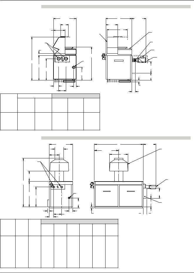
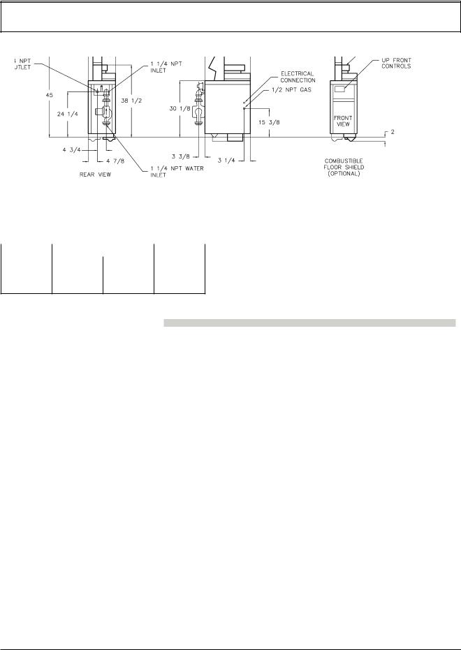
MODELS 0514-0824
29-1/2
|
|
|
|
|
K |
|
|
|
|
|
14-3/4 |
|
|
|
|
|
|
|
|
|
|
|
|
|
|
DRAFT HOOD |
|
|
WATER |
|
|
|
|
|
|
|
|
2 |
|
|
|
|
|
|
|
|
2-3/4 |
|
|
|
|
|
|
|
|
|
|
|
|
|
|
44-1/8 |
|
|
57 |
|
|
|
|
|
GAS |
|
|
|
|
|
|
|
1 NPT |
|
|
|
|
|
|
OUT |
IN |
|
|
|
|
33 |
|
|
|
|
||
|
|
|
|
|
|
|
|
|
|
|
28-1/4 |
|
|
|
|
|
|
|
|
|
|
|
|
|
17 |
|
|
|
|
|
6 |
|
3-3/4 |
||
|
|
|
11-1/8 |
|
|
|
|
|
|
Indoor/Outdoor |
|
|
Dimensions (in inches) |
||||
|
|
|
|
|
Width |
Flue |
|
|
Model |
Input |
Recovery |
|
Diameter |
L |
|||
Number |
MBH |
GPH* |
|
|
A |
K |
|
|
WH-0514 |
511.5 |
508 |
|
32-3/4 |
10 |
|
25-3/8 |
|
WH-0624 |
627.0 |
623 |
|
37-1/2 |
12 |
|
29-1/2 |
|
WH-0724 |
726.0 |
722 |
|
41-5/8 |
12 |
|
34-1/4 |
|
WH-0824 |
825.0 |
820 |
|
45-3/4 |
14 |
|
38-1/2 |
|
* Recovery based on manufacturer’s rating. |
|
|
|
|||||
A |
19-1/2 |
A/2
L
STACKLESS TOP
INDOOR |
|
ELECT |
|
OUTDOOR |
CONN |
||
|
PUMP (OPTIONAL)
PUMP COVER (OPTIONAL)
14-1/2
10
COMBUSTIBLE |
2-1/4 |
FLOOR SHIELD (OPTIONAL) 5
NOTE:
Ratings are shown for elevations up to 2,000 feet. For elevations over 2,000 feet, reduce ratings 4% for each 1,000 feet above sea level.
MODELS 0962-1826
|
|
|
|
32-1/2 |
|
|
|
|
|
A |
|
|
|
|
K |
|
|
|
|
A/2 |
|
|
|
|
|
|
|
|
|
|
L |
|
|
|
|
11-1/4 |
|
|
|
|
|
|
|
|
|
WATER |
|
|
|
|
|
|
|
|
|
|
2-1/2 |
|
|
|
|
|
|
|
|
|
|
23-5/8 |
|
|
|
|
|
|
|
|
|
B |
|
|
|
|
|
|
|
|
|
|
|
C |
|
IN |
G |
|
|
|
|
|
|
|
|
OUT |
|
|
|
|
|
||
|
|
|
|
|
|
|
|
|
|
|
|
|
27-3/4 |
|
|
GAS |
|
|
|
|
|
|
|
|
|
|
14 |
|
|
|
|
|
|
|
2-1/2 |
|
5-1/8 |
|
|
COMBUSTIBLE FLOOR SHIELD |
|||
|
|
|
|
1-1/8 |
|
(OPTIONAL) |
||||
|
|
|
|
|
11-1/8 |
|
|
|
||
|
|
|
|
|
|
|
|
|
||
|
|
|
6 |
|
|
|
|
|
|
|
|
|
|
|
|
Dimensions (in inches) |
|
|
|
||
|
|
|
|
Overall |
Jacket |
Gas |
|
Flue |
|
|
Model |
Input |
Recovery |
Width |
Height |
Height |
Conn. |
Diameter |
|
||
A |
B |
C |
G |
|
K |
|
L |
|||
Number |
MBH |
GPH* |
|
|
||||||
WH-0962 |
961.7 |
956 |
52-3/8 |
68-3/4 |
33-1/2 |
1 |
|
14 |
|
28 |
WH-1125 |
1124.7 |
1118 |
59-1/4 |
74-1/2 |
33-1/2 |
1 |
|
16 |
|
32 |
WH-1223 |
1222.5 |
1215 |
63-5/8 |
74-1/2 |
33-1/2 |
1-1/4 |
|
16 |
|
32 |
WH-1336 |
1336.6 |
1328 |
68-5/8 |
76-1/2 |
33-1/2 |
1-1/4 |
|
18 |
|
36 |
WH-1468 |
1467.0 |
1458 |
74-7/8 |
76-1/2 |
33-1/2 |
1-1/4 |
|
18 |
|
36 |
WH-1631 |
1630.0 |
1620 |
82-1/8 |
79-1/2 |
36-1/2 |
1-1/4 |
|
18 |
|
36 |
WH-1826 |
1825.6 |
1814 |
89-3/8 |
81-1/2 |
36-1/2 |
1-1/4 |
|
20 |
|
40 |
* Recovery based on manufacturer’s rating. |
|
|
|
|
|
|
||||
|
|
|
|
|
|
|
|
10 |
|
|
19-1/2
INDOOR
DRAFT
HOOD
PUMP (OPTIONAL)
|
14-1/2 |
|
11-3/4 |
ELECT |
|
CONN |
||
|
||
|
(J-BOX) |
 5
5 
NOTE:
Ratings are shown for elevations up to 2,000 feet. For elevations over 2,000 feet, reduce ratings 4% for each 1,000 feet above sea level.
MODELS 0926-1758
|
|
32-1/2 |
|
|
|
|
H |
|
|
|
|
|
|
|
|
|
|
|
46-3/4 |
|
|
OUT |
IN |
|
G |
|
|
|
|
|
|
|
|
|
27-3/4 |
|
|
|
GAS |
|
|
|
|
|
|
14 |
|
|
|
|
|
|
5-1/8 |
1-1/8 |
|
|
|
|
11-1/8 |
|
|
|
|
6 |
|
|
|
|
|
|
|
|
|
|
|
|
|
|
|
Dimensions (in inches) |
|||
|
|
|
Width |
|
Gas |
Water |
Model |
Input |
Recovery |
|
Conn. |
Conns. |
|
A |
|
G |
H |
|||
Number |
MBH |
GPH* |
|
|||
WH-0926 |
926.0 |
920 |
52-3/8 |
|
1 |
2-1/2 |
WH-1083 |
1083.0 |
1076 |
59-1/4 |
|
1 |
2-1/2 |
WH-1178 |
1178.0 |
1171 |
63-5/8 |
|
1-1/4 |
2-1/2 |
WH-1287 |
1287.0 |
1279 |
68-5/8 |
|
1-1/4 |
2-1/2 |
WH-1414 |
1413.0 |
1404 |
74-7/8 |
|
1-1/4 |
2-1/2 |
WH-1571 |
1570.0 |
1560 |
82-1/8 |
|
1-1/4 |
2-1/2 |
WH-1758 |
1758.0 |
1747 |
89-3/8 |
|
1-1/4 |
2-1/2 |
* Recovery based on manufacturer’s rating. |
|
|
||||
MODELS 2100-4000
A |
19-1/2 |
|
PUMP COVER (OPTIONAL)
PUMP (OPTIONAL)
14-1/2
ELECT 11-3/4 CONN
(J-BOX)
COMBUSTIBLE FLOOR SHIELD |
|
(OPTIONAL) |
5 |
|
NOTE:
Ratings are shown for elevations up to 2,000 feet. For elevations over 2,000 feet, reduce ratings 4% for each 1,000 feet above sea level.
|
|
|
|
|
|
|
|
|
|
|
|
|
Dimensions (in inches) |
|
|
||
|
|
|
|
Overall |
Gas |
Water |
|
Flue |
Model |
Input |
Recovery |
Width |
Height |
Conn. |
Conns. |
|
Diameter |
A |
B |
G |
H |
|
K |
|||
Number |
MBH |
GPH* |
|
|||||
WH-2100 |
2100.0 |
2087 |
61 |
68-1/4 |
** |
3 |
|
24 |
WH-2500 |
2499.0 |
2484 |
70 |
68-1/4 |
** |
3 |
|
26 |
WH-3001 |
3000.0 |
2982 |
81-1/4 |
68-1/4 |
2 |
3 |
|
28 |
WH-3500 |
3500.0 |
3479 |
92-1/2 |
68-1/4 |
2 |
3 |
|
30 |
WH-4001 |
4000.0 |
3976 |
103-3/4 |
68-1/4 |
2 |
3 |
|
32 |
|
|
|
|
|
|
|
|
|
* Recovery based on manufacturer’s rating. |
|
|
|
|
||||
** 1-1/2” or 2” contingent on code requirements |
|
|
|
|
||||
|
|
|
|
|
|
|
11 |
|
MODEL,
NOTE:
Ratings are shown for elevations up to 2,000 feet. For elevations over 2,000 feet, reduce ratings 4% for each 1,000 feet above sea level.
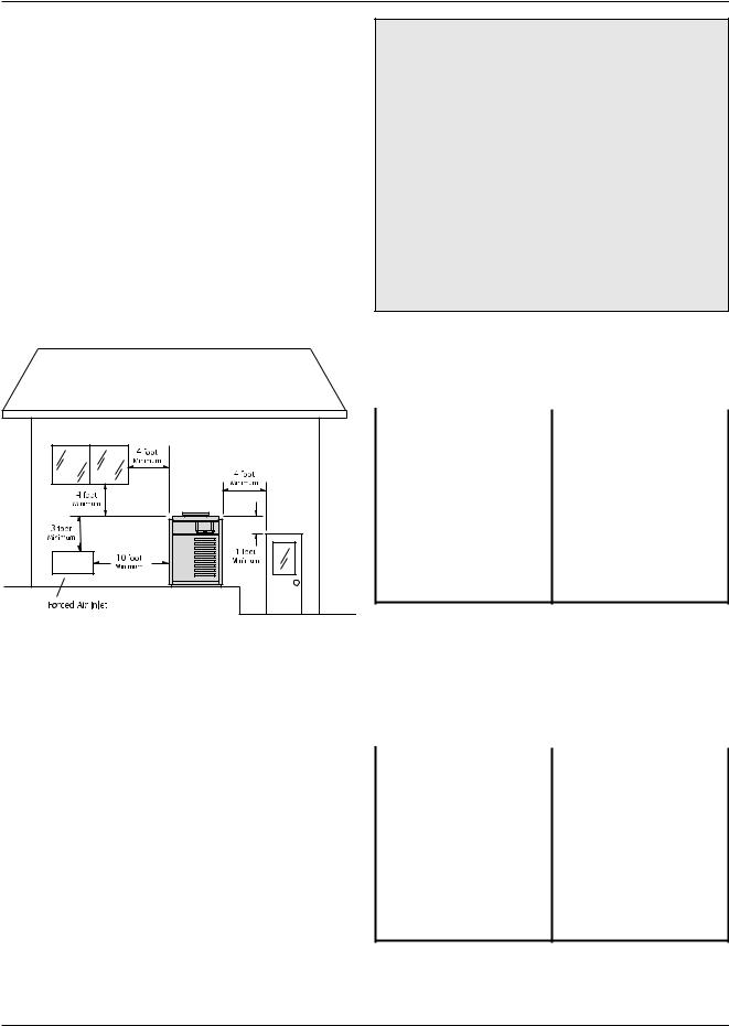
Outdoor Water Heaters
These heaters are design certified for outdoor installation. Heaters must not be installed under an overhang of less than three (3) feet from the top on the heater. Three (3) sides must be open in the area under the overhang. Roof water drainage must be diverted away from the heaters installed under overhangs with the use of gutters.
The point from where the flue products exit the heater must be a minimum of four (4) feet below, four (4) feet horizontally from or one (1) foot above any door, window or gravity inlet to a building. The top surface of the heater shall be at least three (3) feet above any forced air inlet, or intake ducts located within ten (10) feet horizontally.
CAUTION: Combustion air must not be contaminated by corrosive chemical fumes which can damage the heater. Measures must be taken to prevent the entry of corrosive chemical fumes to the combustion and ventilation air supply. Such chemicals include, but are not limited to, chlorinated and/or fluorinated hydrocarbons such as found in refrigerants, aerosol propellants, dry-cleaning fluids, degreasers, and paint removers. Other harmful elements may come from bleaches, air fresheners, or mastics. Vapors from these types of products can form corrosive acid compounds when burned in a gas flame. The resulting acidic condensate can damage or substantially reduce the life of the heater. It may become necessary to provide outside air directly to the heater in order to avoid this problem.
a. All Air From Inside The Building:
Each opening shall have a minimum net free square inches as noted:
Fig. 3: Outdoor Clearances from Openings |
High Wind Conditions (Outdoor |
Units Only) |
In areas where high winds are frequent, it may be necessary to locate the heater a minimum of 3' from high vertical walls, or install a wind break so the heater is not in direct wind current.
Combustion Air (Indoor Units Only) Air for Combustion and Ventilation
The heater must have both combustion and ventilation air. Minimum requirements for net free air supply openings are 12 inches from ceiling for ventilation and 12 inches from the floor for combustion air as outlined in ANSI Z223.1, and any local codes that may have jurisdiction.
|
Square |
|
Square |
|
Model |
Inches |
Model |
Inches |
|
0133 |
136 |
1223 |
1223 |
|
0182/0181 |
181 |
1336 |
1337 |
|
0260/0261 |
264 |
1468 |
1467 |
|
0330/0331 |
334 |
1631 |
1630 |
|
0400/0401 |
399 |
1826 |
1826 |
|
0514 |
512 |
2100 |
2100 |
|
0624 |
627 |
2500 |
2499 |
|
0724 |
726 |
3001 |
3000 |
|
0824 |
825 |
3500 |
3500 |
|
0962 |
962 |
4001 |
4000 |
|
1125 |
1125 |
|
|
|
BOLD TYPE indicates Low NOx models.
Table E: All Air From Inside The Building
b. All Air From Outdoors:
When air is supplied directly from outside of building, each opening shall have a minimum net free square inches as noted:
|
Square |
|
Square |
|
Model |
Inches |
Model |
Inches |
|
0133 |
34 |
1223 |
306 |
|
0182/0181 |
46 |
1336 |
335 |
|
0260/0261 |
66 |
1468 |
367 |
|
0330/0331 |
84 |
1631 |
408 |
|
0400/0401 |
100 |
1826 |
457 |
|
0514 |
128 |
2100 |
525 |
|
0624 |
157 |
2500 |
625 |
|
0724 |
182 |
3001 |
750 |
|
0824 |
207 |
3500 |
875 |
|
0962 |
241 |
4001 |
1000 |
|
1125 |
282 |
|
|
|
BOLD TYPE indicates Low NOx models.
Table F: All Air From Outdoors
12

NOTE: If louvers, grills or screens are used on the openings, obtain the net free area from their supplier or manufacturer. If the design free area of a louver is not known nor available, it shall be assumed that wood louvers will have 20-25 percent free area and metal louvers will have 60-75 percent free area as specified in the National Fuel Gas Code.
Venting
WARNING: Examine the venting system at least
once a year. Check all joints and vent pipe
connections for tightness, corrosion or deterioration.
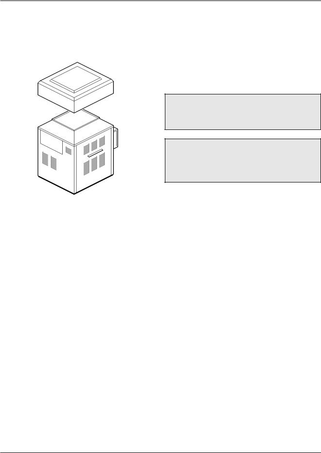
Outdoor Installations
Model 0133
1.Remove the front (4) screws.
2.Line up outdoor top vent opening over heater vent opening.
3.Lower outdoor top onto unit lining up slots in the outdoor top with screws holes in jacket top.
4.Reinstall (5) screws to secure jacket top and outdoor top to unit.
Fig. 4: Outdoor Top Installation
Models 0181-0401 and 0182-0400
OUTDOOR |
|
|
|
|
|
|
|
|
|
|
|
|
|
|
|
|
|
|
|
|
|
|
|
|
|
|
|
|
|
|
|
|
|
|
|
|
|
|
|
|
|
|
|
|
|
|
|
|
|
|
|
|
|
|
|
|
|
|
|
|
|
|
|
|
|
|
|
|
|
|
|
|
|
|
|
|
|
|
|
|
|
|
|
|
|
|
|
|
|
|
|
|
|
|
|
|
|
|
|
|
|
|
|
|
|
|
|
|
|
|
|
|
|
|
|
|
|
|
|
|
|
|
|
|
|
|
|
|
|
|
|
|
|
|
|
|
|
|
|
|
|
|
|
|
|
|
|
|
|
|
|
|
|
|
|
|
|
|
|
|
|
|
|
|
|
|
|
|
|
|
|
|
|
|
|
|
|
|
|
|
|
|
|
|
|
|
|
|
|
|
|
|
|
|
|
|
|
|
|
|
|
|
|
|
|
|
|
|
|
|
|
|
|
|
|
|
|
|
|
|
|
|
|
|
|
|
|
|
|
|
|
|
|
|
|
|
|
|
|
|
|
|
|
|
|
|
|
|
|
|
|
|
|
|
|
|
|
|
|
|
|
|
|
|
|
|
|
|
|
|
|
|
|
|
|
|
|
|
|
|
|
|
|
|
|
|
|
|
|
|
|
|
|
|
|
|
|
|
|
|
|
|
|
|
|
|
|
|
|
|
|
|
|
|
|
|
|
|
|
|
|
|
|
|
|
|
|
|
|
|
|
|
|
|
|
|
|
|
|
|
|
|
|
|
|
|
|
|
|
|
|
|
|
|
|
|
|
|
|
|
|
|
|
|
|
|
|
|
|
|
|
|
|
|
|
|
|
|
|
|
|
|
|
|
|
|
|
|
|
|
|
|
|
|
|
|
|
|
|
|
|
|
|
|
|
|
|
|
|
|
|
|
|
|
|
|
|
|
|
|
|
|
|
|
|
|
|
|
|
|
|
|
|
|
|
|
|
|
|
|
|
|
|
|
|
|
|
|
|
|
|
|
|
|
|
|
|
|
|
|
|
|
|
|
|
|
|
|
|
|
|
|
|
|
|
|
|
|
|
|
|
|
|
|
|
|
|
|
|
|
|
|
|
|
|
|
|
|
|
|
|
|
|
|
|
|
|
|
|
|
|
|
|
|
|
|
|
|
|
|
|
|
|
|
|
|
|
|
|
|
|
|
|
|
|
|
|
|
|
|
|
|
|
|
|
|
|
|
|
|
|
|
|
|
|
|
|
|
|
|
|
|
|
|
|
|
|
|
|
|
|
|
|
|
|
|
|
|
|
|
|
|
|
|
|
|
|
|
|
|
|
|
|
|
|
|
|
|
|
|
|
|
|
|
|
|
|
|
|
|
|
|
|
8-3/8" |
|||||
FLOOR BASE |
|
|
|
|
|
|
|
|
|
|
|||||||||
|
|
|
|
|
|
|
|
|
|
|
|
|
|
|
|
|
|
||
|
|
|
|
|
|
|
|
|
|
|
|
|
|
|
|
|
|
|
|
Fig. 5: Outdoor Top Installation
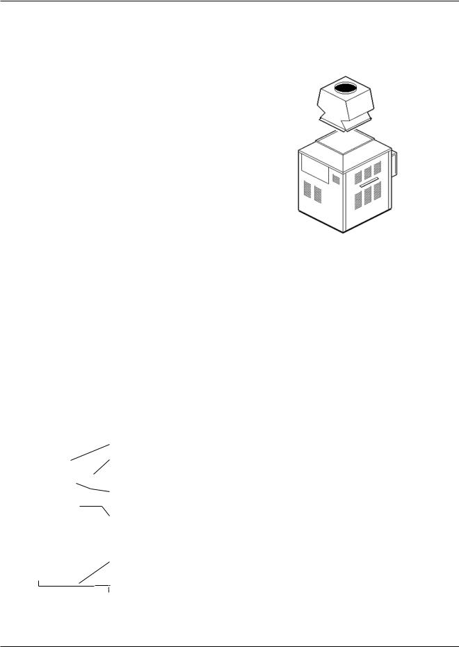
Vent Terminal (Outdoor) Stackless Top
Installation
1.Insert tabs into keyhole (4 places).
2.Snap tabs into keyholes so as not to pull out.
Pagoda Top (Shipped Loose with Heater)
Fig. 6: Outdoor Top Installation
13
Models 0514-0824
1.Lower outdoor "Stackless" top onto unit. Position top so it is centered on unit from side-to-side and front-to-rear.
Fig. 7: Outdoor Top Installation
2.Tighten the (4) screws (Shown below) until they come in contact with the unit jacket top, then evenly tighten all (4) screws to secure to unit.
Fig. 8: Outdoor Top Installation
Models 0926-1758
Heaters are shipped with outdoor vent terminal factory installed.
Models 2100-4001
These units are not certified for outdoor installation.
Indoor Installations
WARNING: Do not use the “one permanent opening” method if the equipment room is under negative pressure conditions or the equipment is common vented with other gas-fired appliances.
WARNING: These heaters must not be connected into any portion of mechanical draft systems operating under positive pressure. To do so may cause the flue products to be discharged into the living space causing serious health injury.
Model 0133
Refer to Fig. 9 on the following page.
1.Shut-off main electrical power switch to heater.
2.Turn heater manual ON/OFF switch, located in upper control panel, to the "OFF" position.
3.Shut-off gas supply and water supply to the heater.
4.Mount drafthood on heater and attach with the 8 sheet metal screws provided. Drafthood should be positioned with the vent sensor located on the front left side as shown.
5.Remove plastic plug from left side of heater jacket and install the plastic grommet provided.
6.Route flue sensor wire harness through the grommet installed in Step 5.
7.Remove door and locate wire from roll out sensor to High Limit with the male/female connector.
8.Disconnect male/female connector and attach to the 2 wires from drafthood vent sensor harness.
14

Fig. 9: Indoor Top Installation
15
Models 0181-0401 and 0182-0400
Vent Terminal/Indoor Stack
Installation
1.Remove the louvered jacket top by removing four
(4) #10 flathead screws.
2.If originally installed, remove "Pagoda" top from the louvered jacket top.
3.Place the inner stack adapter panel over the flue collector inside the heater. Make sure the flanged side of the flue opening is up.
4.Turn the stack (drafthood) upside down and set it down bottom side up.
5.Turn the jacket top panel (removed in step 1) upside down and place it over the stack.
6.Attach the three (3) mounting brackets to the stack using the screws provided and the holes that are pre-drilled in the stack. Make sure the brackets are positioned with the flange near the top side of the stack (see Fig. 10). Caution must be taken not to over tighten and strip the screw threads.
7.Turn the assembled stack and jacket top, right side up. The jacket top will be trapped between the brackets and the top of the stack. Place the stack over the inner adapter panel flanged hole and lower the louvered jacket top panel back into its original position. Reinstall the four (4) green #10 flathead screws removed in step 1 above.
Models 0514-0824
Locate and assemble as shown below. Secure with screws supplied in envelope in carton.
Fig. 11: Indoor Top Installation
Models 0962-1826
Locate and assemble as shown below. Secure with screws supplied in envelope in carton.
SCREW HOLE LOCATION
 3-1/4"
DRAFTHOOD
JACKET TOP PANEL
(part of the heater)
#10 SHEET METAL SCREW (3)  MOUNTING BRACKET (3)
 INNER STACK ADAPTER PANEL FLUE COLLECTOR
(part of heater)
COMBUSTIBLE FLOOR SHIELD
(optional for indoor) 
 2-1/2"
Fig. 10: Indoor Top Installation
Fig. 12: Indoor Top Installation
Models 2100-4001
These models have built-in drafthoods. For proper operation, the drafthood outlet must be connected to the venting system.
16
Loading...