


INSTALLATION & OPERATING
INSTRUCTIONS
Electric
SPA-PAK
Heater
Models
ELS 552-2 & ELS 1102-2
FOR YOUR SAFETY: Do not store or use gasoline or other flammable vapors and liquids or other combustible materials in the vicinity of this or any other appliance. To do so may result in an explosion or fire.
Catalog No. 6100.53V |
Effective: 09-01-15 |
Replaces: 09-28-09 |
P/N 240362 Rev. 23 |

WATER CHEMISTRY (Corrosive water voids all warranties)
For your health and the protection of your pool equipment, it is essential that your |
||||
water be chemically balanced. The following levels must be used as a guide for bal- |
||||
anced water. |
|
|
|
|
Recommended Level(s) |
Fiberglass Pools |
Fiberglass Spas |
Other Pool & Spa |
|
Types |
||||
|
|
|
||
Water Temp. (Deg. F) |
68 to 88 |
89 to 104 |
68 to 104 |
|
|
|
|
|
|
pH |
7.3 to 7.4 |
7.3 to 7.4 |
7.6 to 7.8 |
|
|
|
|
|
|
Total Alkalinity (PPM) |
120 to 150 |
120 to 150 |
80 to 120 |
|
|
|
|
|
|
Calcium Hardness (PPM) |
200 to 300 |
150 to 200 |
200 to 400 |
|
|
|
|
|
|
Salt (PPM) |
4500 MAXIMUM |
4500 MAXIMUM |
4500 MAXIMUM |
|
|
|
|
|
|
Free Chlorine (PPM)* |
2 to 3 |
2 to 3 |
2 to 3 |
|
|
|
|
|
|
Total Dissolved Solids (PPM) |
3000 MAXIMUM** |
3000 MAXIMUM** |
3000 MAXIMUM** |
|
*Free Chlorine MUST NOT EXCEED 5 PPM!
**In salt water chlorinated pools, the total TDS can be as high as 6000 ppm.
•Occasional chemical shock dosing of the pool or spa water should not damage the heater providing the water is balanced.
•Automatic chemical dosing devices and salt chlorinators are usually more efficient in heated water, unless controlled, they can lead to excessive chlorine level which can damage your heater, and which is not covered under warranty. A check valve should be installed between the heater outlet and a chlorinator or other chemical dosing device.
•Further advice should be obtained from your pool or spa builder, accredited pool shop, or chemical supplier for the correct levels for your water.
Rev. 23 reflects the following: Changes to: Water Chemistry on page 2.
2

INTRODUCTION
The Spa-Pak spa Heaters have been designed to pro- vide efficient, pollution-free, electric pool heating while requiring minimal installation. The Spa-Pak consists of a sheathed resistance element installed in a copper tank.
This tank has a 1-1/2 NPT inlet and outlet on the side for plumbing connections. The heater voltage is 208/240V single-phase. The control circuit passes through a manual switch, the temperature control, and the magnetic contactor coil. All items are pre-wired and installed in a powder coated steel case.
It is essential that the heater be installed in accordance with the instructions given herein. Failure to do so may cause damage to the heater and to the equipment to which it is connected, or may prevent the heater from operating in a correct manner. The heater is to be installed in accordance with article 680 of the National Electrical Code ANSI/NFPA No. 70. Consult State and local codes BEFORE installing this unit. Where such codes have requirements beyond the instructions given herein, the codes shall have precedence over these instructions.
Location
These heaters are listed by UL for either indoor or outdoor use. Unit must be mounted on a level base parallel to the ground. Allow 6” clearance at sides and 18” clearance at top and front for maintenance. Secure the unit with 5/16” mounting hardware using the holes provided. The heater must be located where leakage of heat exchanger or connections will not damage the area adjacent to the heater or structure.
Water Connections
|
Check Valve |
|
To Spa |
|
Filter |
|
Chlorinator |
Bypass |
Pump |
|
|
(Customer Installed) |
|
Drain Valve |
|
(Customer Installed) |
|
|
Gate Valve |
|
From Spa |
NOTE: PVC pipe may be used.
NOTE: When using two-speed pumps, do not install gate valve on inlet.


 NPT
NPT


 NPT
NPT
The Spa-Pak has 1-1/2” male NPT inlet and outlet connections at the right side of the heater. The inlet is at the base of the heater and must be piped directly to the filter discharge to ensure proper flow direction. Minimum flow rate through the heater is 15 gpm, maximum is 60 gpm. If this is exceeded, an external bypass must be added as shown. Unions should be used on piping connections. A shut-off valve should be included on the heater inlet to prevent draining the spa when performing maintenance.
CAUTION: No shut-off valves are to be installed in the piping between the heater outlet and the spa. Any chlorinators, valves, etc., that can cause return line blockage will void the warranty.
Automatic Chlorinators and Chemical Feeders
All chemicals must be introduced and completely diluted into the spa water before being circulated through the heater. Do not place chlorine tablets or bromine sticks in the skimmer. High chemical concentrations will result when the pump is not running (e.g. overnight).
Chlorinators must feed downstream of the heater and have an anti-siphoning device to prevent chemical backup into the heater when the pump is shut off.
3
CAUTION: High chemical concentrates from feeders and chlorinators that are out of adjustment will cause very rapid corrosion to the heater. Such damage is not covered under the warranty.
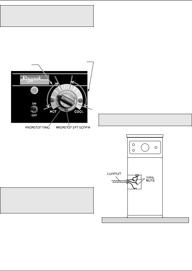
Thermostat
The heater thermostat located on the front of the unit, may be set for any desired spa temperature.
TYPICAL COMFORTABLE |
TYPICAL COMFORTABLE |
|
TEMPERATURE |
TEMPERATURE |
|
RANGE FOR SPAS |
RANGE FOR POOLS |
|
|
|
|
|
|
|
codes. Keep wire runs as short as possible to minimize voltage drop. Bring wires of size indicated from a fused disconnect switch (customer furnished) with an amp rating of at least 125% of the amp rating shown on the spa heater nameplate. A ground lug is provided for connection to the supply ground. A wiring diagram of the heater is shown at right. It is also affixed to the inside front cover of the units.
Field Wiring
Heater requires three-wire service. With 240 VAC there are two hot wires and a grounding conductor. Even when metallic conduit is used, the grounding conductor must be run to the supply ground.
Field wiring connections are made to the electrical entry at the left side of the unit. A hole in the jacket is provided for a 1” trade size conduit hub. The location of the field wiring box is shown below. Wire nuts are used to connect all leads except the grounding conductor, for which a pressure lug is provided.
NOTE: Heater grounding conductor shall be the same or larger than the live power supply conductor.
Maximum Temperature Setpoint
(Knobstop Adjustment)
Adjustment to a different maximum setting is a simple task. Loosen the small set screw on the knobstop and rotate the knobstop ring until vertical “stop” tab is at the desired maximum setting. Retighten the set screw.
ELECTRICAL
WARNING: The power supply circuit to this heater shall be protected by a ground-fault circuit interrupter (GFCI), in accordance with Art. 680 of the latest edition of the National Electrical Code (NEC). Failure to do so could result in severe personal injury or death.
The GFCI devices shall be of the self-contained types, circuit breaker types or the receptacle types. Feeder ground-fault protection is not required where GFCI is already provided in the branch circuits or receptacles supplying power to the heater.
Electrical Disconnect
An electrical disconnect and over-current protection device must be provided in accordance with local
4
Recommended Wire Sizes for Field Connection
Use type THWN copper wire to the unit, with the AWG wire sizes (Internal wire sizes may differ) listed in Table A on the following page.
 Loading...