

Page 1

User Manual for Commercial Series Net DVR
Commercial Series Net DVR
User Manual
(V2.0)
Thank you for purchasing our embedded Net DVR. This manual is applicable for QSD42208,
QSC26408, and QSC26416 Net DVR, as well as the QSF2648008 and QSF2648016 Enterprise
DVR models. Please read this User Manual carefully to ensure that you can use the device
correctly and safely.
DISCLAIMER: The contents of this Manual are subject to change without notice; we are
also not responsible for typing errors or errors of omission.
Contact Us:
Q-See Products
8015 E. Crystal Dr
Anaheim, CA 92807
Website:
http://www.q-see.com
Customer Service:
Phone: 877-998-3440 x 538
Email: cs@dpsi-usa.com
Tech Support:
Phone: 877-998-3440 x 539
Email: ts@dpsi-usa.com
Fax:
714-998-3509
Rev 082907D
Page 1 Total 121
Page 2

User Manual for Commercial Series Net DVR
Index
V ersion Description ........................................................................................................................... 4
Chapter 1 Product Introduction.................................................................................................. 6
1.1 Summary ................................................................................................................... 6
1.2 Features ..................................................................................................................... 6
Chapter 2 Installation ................................................................................................................. 8
2.1 Checking the DVR and Its Accesso ries..................................................................... 8
2.2 HDD Installation ....................................................................................................... 8
2.3 Rear Panel Description .............................................................................................. 9
2.3.1 8-ch QSD42208 Rear Panel .............................................................................. 9
2.3.2 8-ch/16-ch QSC26408/16 Rear Panel ............................................................. 10
2.4 External Alarm In/Out Connection ......................................................................... 12
Chapter 3 Operational Instructions .......................................................................................... 13
3.1.1 8-ch QSD42208 Front Panel ................................................................................... 13
3.1.2 8-ch QSC26408 Front Panel ................................................................................... 15
3.1.3 16-ch QSC26416 Front Panel ................................................................................. 17
3.2 Remote Control ....................................................................................................... 19
3.3 Menu Description .................................................................................................... 21
3.3.1 Menu Items...................................................................................................... 21
3.3.2 Menu Operation .............................................................................................. 22
3.4 Character Input ........................................................................................................ 25
Chapter 4 Basic Operation Guide ............................................................................................ 26
4.1 Power on ................................................................................................................. 26
4.2 Preview.................................................................................................................... 26
4.3 User name and password ......................................................................................... 29
4.4 PTZ Control ............................................................................................................ 31
4.5 Manual Record ........................................................................................................ 33
4.6 Playback .................................................................................................................. 34
4.7 Backup Recorded Files ........................................................................................... 39
4.8 Shut Down DVR ..................................................................................................... 41
Chapter 5 Main and Aux Output Function ............................................................................... 43
5.1 Main and aux output................................................................................................ 43
5.2 Main and Aux output preview ................................................................................. 44
5.3 Main and Aux output playback ............................................................................... 47
5.4 Main or Aux output to control PTZ ......................................................................... 48
Chapter 6 Parameters Setup Guide .......................................................................................... 49
6.1 Administrator and Password ................................................................................... 49
6.2 Add and Delete User ............................................................................................... 51
6.3 Unit Name and Device ID ....................................................................................... 54
6.4 V ideo Output Standard and VGA Setup .................................................................. 55
6.5 OSD Setup............................................................................................................... 56
6.6 V ideo Parameters Setup .......................................................................................... 59
Page 2 Total 121
Page 3

User Manual for Commercial Series Net DVR
6.7 Mask Area Setup ..................................................................................................... 60
6.8 V iew T ampering Alarm ........................................................................................... 62
6.9 V ideo Loss Alarm .................................................................................................... 64
6.10 Motion Detection Alarm ......................................................................................... 66
6.11 Preview Properties .................................................................................................. 69
6.12 Recording Setup ...................................................................................................... 71
6.13 External Alarm Input and Relay Output .................................................................. 75
6.14 Network Parameters ................................................................................................ 79
6.141 Accessing the DVR over a network ...................................................................... 81
6.142 Accessing the DVR from a remote computer ....................................................... 82
6.15 PTZ ......................................................................................................................... 83
6.16 RS232 setup ............................................................................................................ 87
6.17 Exceptions ............................................................................................................... 92
6.18 T ransaction Information .......................................................................................... 93
Chapter 7 Utilities .................................................................................................................... 97
7.1 Save Parameters ...................................................................................................... 97
7.2 Restore Parameters .................................................................................................. 97
7.3 Upgrade ................................................................................................................... 98
7.4 Hard Disk Management .......................................................................................... 99
7.5 Clear Alarm Out ...................................................................................................... 99
7.6 Reboot ..................................................................................................................... 99
7.7 Power Off ................................................................................................................ 99
7.8 V iew Log ................................................................................................................. 99
7.9 System Information ............................................................................................... 102
Chapter 8 Firmware Upgrade ................................................................................................ 103
8.1 FTP Server Setup .................................................................................................. 103
8.2 Upgrade Mode....................................................................................................... 105
Appendix A HDD Capacity Calculation............................................................................ 106
Appendix B DVR Connect Cable Definition .................................................................... 107
1 How to make a RS-485 connect cable .......................................................................... 107
2 How to make a UTP network connect cable ................................................................. 107
3 How to make a RS-232 connect cable .......................................................................... 109
Appendix C Specifications ................................................................................................ 112
Appendix D Quick Search Function T able ........................................................................ 115
Appendix E Troubleshoot ing ........................................................................................... 117
Appendix F Product Service ............................................................................................ 1 19
Appendix G Cu stomer Information Card .......................................................................... 120
Page 3 Total 121
Page 4

User Manual for Commercial Series Net DVR
Version Description
Version 2.0 built 070206:
The new version firmware DVR has the following new features:
1. Supports USB mouse
Recommended USB mouse model list:
Logitech: M-UV83
Benq: M800
ViewSonic: MC204
Philips: SPM4500BB/93
LG: LGIM-ML208
GlodFly: GF-OP718
Newmen: MS0270 (www.newmen.com.cn
Agiler: A GM-018LU (www.agilertech.com)
Citu: CH-3090 (www .citu.cn
2. Supports USB external DVD backup
Recommended USB external DVD model list:
LG GSA-E10L
BENQ EW164B
Samsung SE-S164
3. Supports DS-1000KI network keyboard
4. Supports E-SATA HDD backup
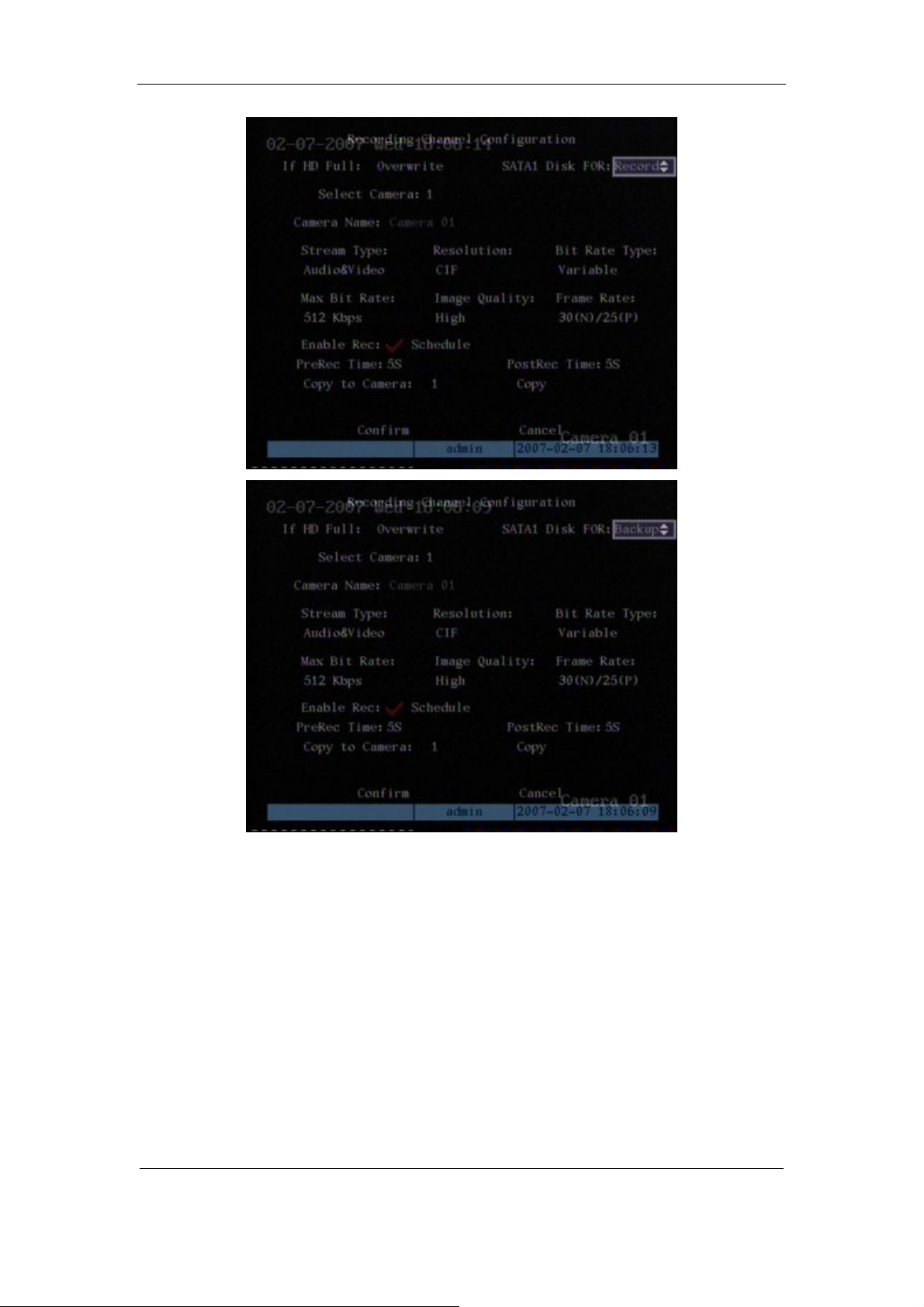
E-SATA interface in QSD42208, QSC26408, and QSC26416 model DVRs is optional. 1st
internal SATA interface can be extended to E-SATA (external SATA) interface. In DVR
“Recording” menu, you can select 1st SATA HDD as either “Recording” or “Backup” work mode.
)
)
Page 4 Total 121
Page 5
User Manual for Commercial Series Net DVR
If you select “Backup” mode, in D VR “Playback” menu, you can select SATA HDD for
backup.
5.Solved some old version bugs
VGA black screen and Aux audio output issues
Page 5 Total 121
Page 6

User Manual for Commercial Series Net DVR
Chapter 1 Product Introduction
1.1 Summary
The Commercial series network digital video recorder is a n excellent digital surveillance product.
It uses the embedded MCU and embedded operating system (RTOS), combining the most
adva nced technology in the Information Industry such as vide o and audio encoding/decoding, ha rd
disk recording and TCP/IP. The firmware is burned into flash memory, more stable and reliable.
The Commercial series device has both the features of digital video recorder (DVR) and
digit al vi de o server (D VS) . It ca n wor k st a nd a lo ne, a l so b e us ed t o b ui ld a p ower f ul s ur vei l la nce
network, widely used in banking, telecommunications, transportation, factories, warehouses,
irrigation, etc.
1.2 Features
Compression
l Supports 16 channnels video input (PAL/NTSC) at most. Each channel is independent,
H.264 hardware compression and real time (PAL: 25 FPS, NTSC: 30FPS). Support both
variable bitrate and variable frame rate.
l Supports 16 channels audio input at most. Each channel is independent, OggVorbis
compression and bitrate is 16Kbps.
l Compresse d video a nd audio a re syn chrono us. You ca n select either mixed st ream or
only vide o stream.
l Supports 4CIF, DCIF, 2CIF, CIF and QCIF resolution (depending on model).
l Supports multi area motion detection.
l Supports OSD and changeable OSD position.
l Supports LOGO and changeable LOGO position.
Local functions
Record
l Supports multiple record type, including real time, manual record, motion detection,
external alarm, motion&alarm, motion|alarm.
l Supports 8 SATA HDDs and each HDD can support 2000GB maximum.
l Supports FAT32 file system.
l Supports HDD S.M.A.R.T technology.
l Supports cycle or none cycle record.
l Supports backing up the recorded files and clips. Supports USB flash memory, USB
HDD, USB CD-R/W, USB DVD-R/W, SATA DVDRW/CDRW HDD for backup.
Page 6 Total 121
Page 7

User Manual for Commercial Series Net DVR
Preview and playback
l Supports BNC analog moniotor and VGA output for main output
l Supports one aux video and audio input
l Supports multiple preview modes.
l Supports sensitive area mask.
l Supports camera spiteful block alarm.
l Supports 2-ch synchronous playback. Support play forward, backward, pause, frame by
frame, etc.
l Supports play back by files or by time.
l Displays local record status.
PTZ
l Support s man y PTZ pr otocol s.
l Supports preset, sequence and cruise.
Alarms
l Supports exception alarm, motion detection alarm, external alarm, etc.
Others
l Supports IR control.
l Supports RS-485 keyboard.
l Supports multi-level user management.
Network
l Supports TCP, UDP, RTP, Multicast for network preview.
l Supports PPPoE for broad band access.
l Supports PSTN for narrow band access.
l Supports remote parameters setup.
l Alarm information can be sent to remote center.
l Network control PTZ.
l Network record real time stream.
l Network downl oad and pla yback of the r ecorded files in DVR.
l Remotely upgrade the firmware.
l RS-23 2 suppor ts tra nsparent chann el funct ion so t hat th e remote PC can us e DVR t o
control serial devices.
l Supports bi-directional voice talk or one-way voice broadcast.
l Supports IE to preview and config DVR.
l Support log.
Development support
l Provides networ k S DK.
l Pr ovides client demo source code.
Page 7 Total 121
Page 8

User Manual for Commercial Series Net DVR
Chapter 2 Installation
Warning: Before you install the DVR, please make sure the power to the DVR is
switched off.
2.1 Checking the DVR and Its Accessories
When you ge t the product , check that all the items a re incl uded in your product pa ckage.
There is a list in the package. If any of the items are missing, please contact your dealer.
2.2 HDD Installation
Installation notice
The DVR has no HDD when leaving factory. Based on the record schedule, you can calculate
the total capacity you need (refer to Appendix A). Please ask the specialist to disassembly the
DVR a nd insta ll HD D. If the vendor you pur cha sed the DVR fro m did n ot incl ude a H DD have
HDD installed by qualified technicians.
Installation instrument
One Phillips screw driver.
HDD installation
1. Open the DVR box.
2. Take off the HDD mounting plate.
3. Place the HDD on the mounting plate and attach it with screws.
4. Attach the mounting plate in the DVR.
5. Connect the ATA data cable correctly.
6. Plug the HDD power connector into the HDD.
7. Cover and re-attach the DVR box lid.
Note: After you install the HDDs, you must format them. Please re fer to section 6.4. If your
vendor supplied the DVR with HDDs this may have already been done for you.
Page 8 Total 121
Page 9

User Manual for Commercial Series Net DVR
2.3 Rear Panel Description
2.3.1 8-ch QSD42208 Rear Panel
Index Physical Interface Description
Video Input
1
Loop Back Ports
2
Main video Output
3
4
VGA Interface
RS-232/Keyboard
5
Interface
RJ45 Ethernet Port
Keyboard Interface
RS-485
6
External Alarm Input
Standard BNC.
Standard BNC.
Connect CCTV monitor, output video a nd menu.
VGA display.
Connect RS-232 devices. Refer to Appendix B for pin
definition.
Connect network devices. Refer to Appendix B for pin
definition.
Can use Hikvision DS-1000K1, DS-1002K1, DS1003K1
PTZ connection. Using T+/T- to connect PTZ.
4 sensor alarm in.
Relay Output
7
GND
8
AC Input
9
E-SATA
2 replay output .
Ground
100~240VAC
Optional. Extend 1st internal SATA to E-SATA.
Page 9 Total 121
Page 10
User Manual for Commercial Series Net DVR
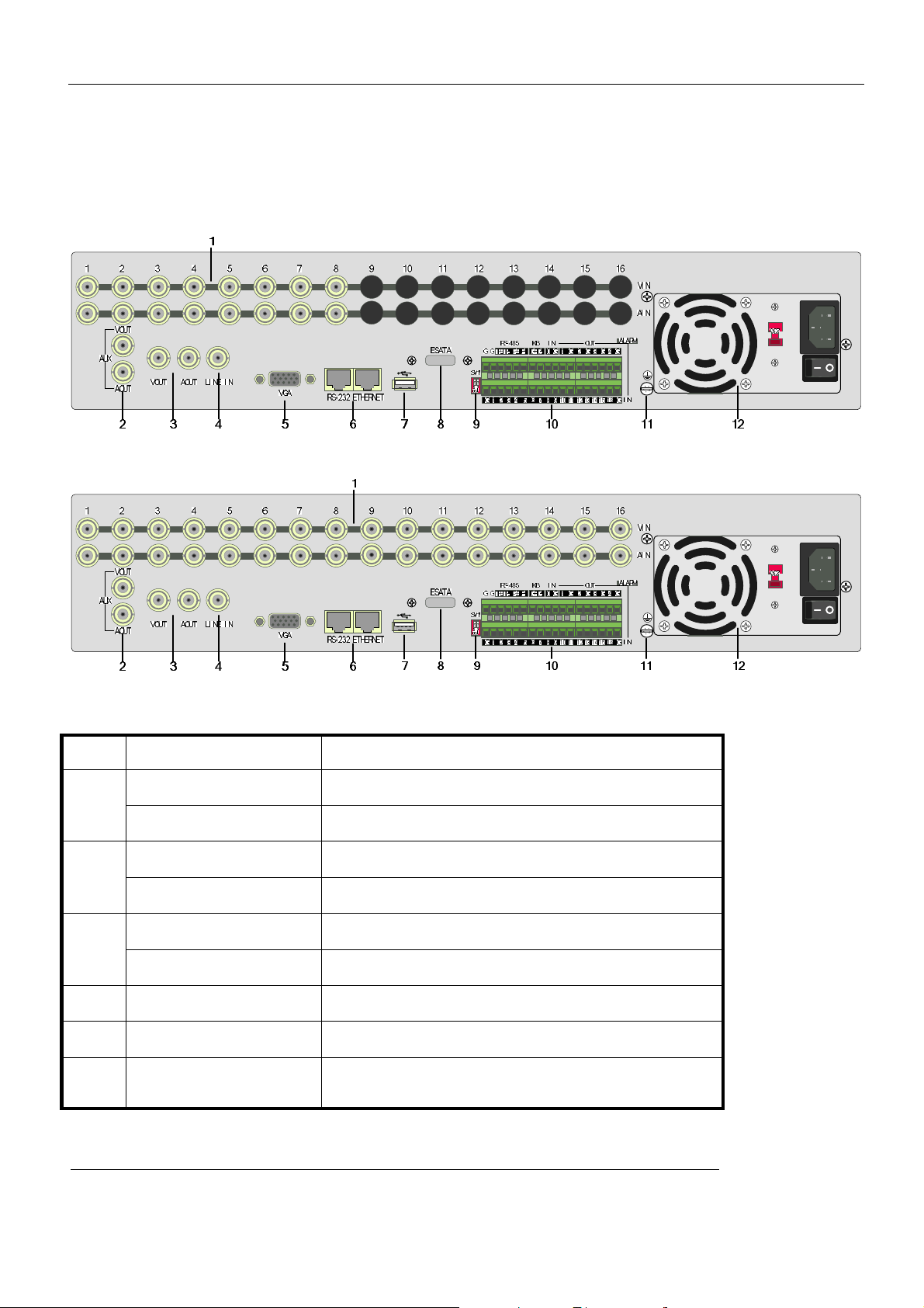
2.3.2 8-ch/16-ch QSC26408/16 Rear Panel
QSC26408 Rear Panel
QSC26416 Rear Panel
Index Physical Interface Description
Video Input
Standard BNC.
1
Audio Input
Aux video Output
Standard BNC.
Spot monitor for video preview and playback.
2
Aux audio Output
Main video output
Spot monitor for audio preview and playback.
Mai n monitor for vide o and me nu.
3
Main audio output
4
Line In
5
VGA Interface
6
RS-232
Mai n monit or for audi o previ ew an d playb ack.
Audio line input for voice talk.
VGA display.
Connect RS-232 devices. Refer to Appendix B for pin
definition.
Page 10 Total 121
Page 11

User Manual for Commercial Series Net DVR
Connect network devices. Refer to Appendix B for pin
7
8
9
10
11
12
RJ45 Network Port
USB Interface
E-SATA
SW1
RS-485
Keyboard Interface
External Alarm Input
Relay Output
GND
AC Input
definition.
USB memory disk, USB HDD, USB CD-R/W, USB DVD
or USB mouse.
Optional. Extend 1st internal SATA to E-SATA.
RS-485 terminal resistor switch. Default is off. The
resistor is 120Ohm.
PTZ connection. Using T+/T- to connect PTZ.
Using D+/D- for keyboard and DVR cascade connection.
Can use Hikvision DS-1000K1, DS-1002K1, DS1003K1
16 sensor alarm in.
4 replay output .
Ground
100~240VAC
Page 11 Total 121
Page 12
User Manual for Commercial Series Net DVR
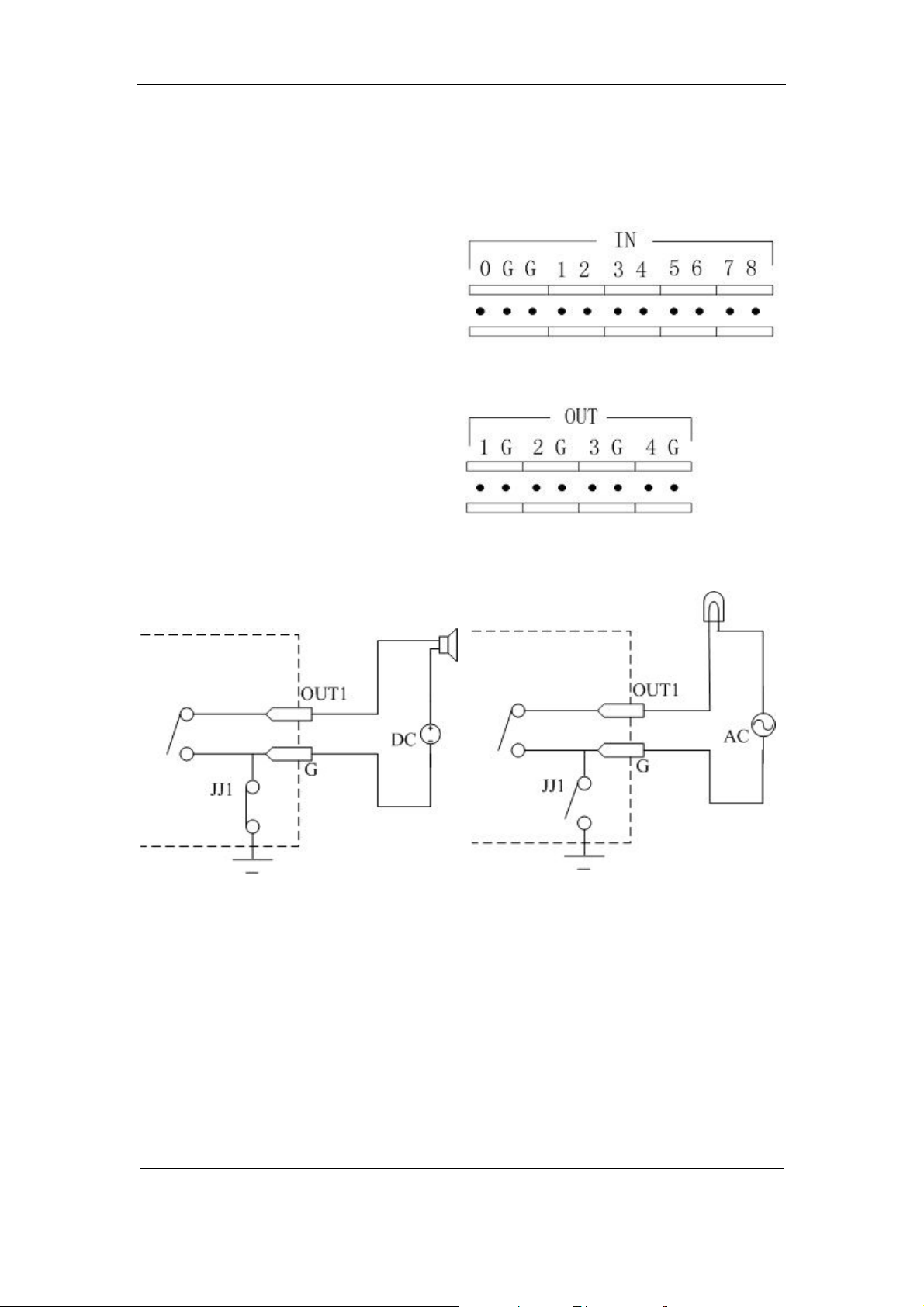
2.4 External Alarm In/Out Connection
Alarm input port (drp node):
G (GND): Connect the GND of sensor.
1~8: Alarm input, support normal
open/normal close.
0: Reserved.
Alarm output:
1G~4G: 4 relay output.
Alarm output connection
Please note the usage of jumper JJ1. If you use DC, either connection is OK. We suggest you
use DC under 12V, 1A.
If you use AC, please open the jumper. There are 4 jumpers (JJ1, JJ2, JJ3 and JJ4) on DVR
main board, corresponding with 4 alarm output. The default is closed.
Warning: If you use AC input for relay outpu t, please open the jumpers.
Page 12 Total 121
Page 13

User Manual for Commercial Series Net DVR
Chapter 3 Operational Instructions
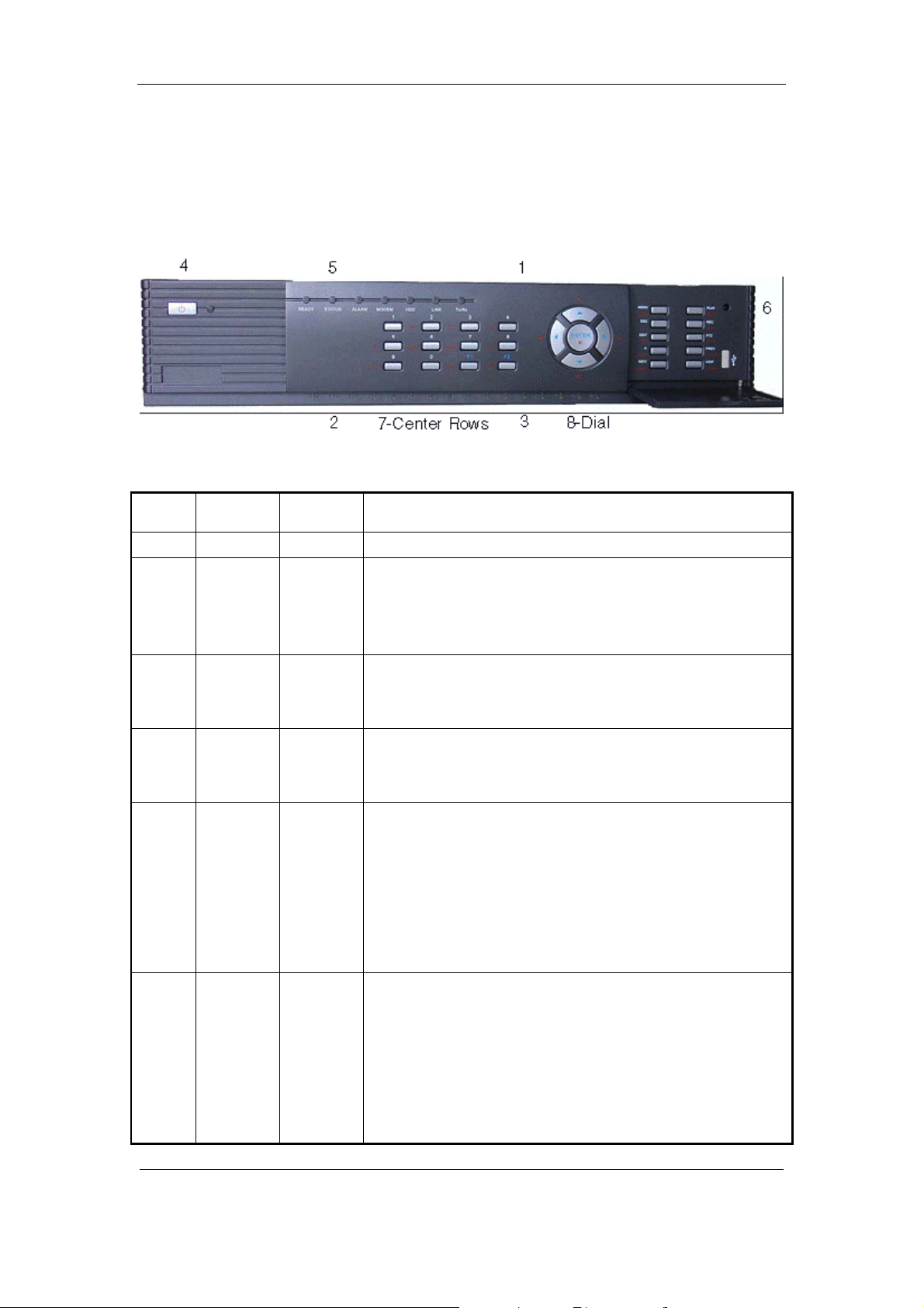
3.1.1 8-ch QSD42208 Front Panel
Index Type Name Description
1 USB Port USB flash drive, HDD, DVDRW/CDRW or Mouse
2 Status
Lamps
3 POWER POWER Device switch with power indicator lamp. Green means DVR is
4 Compound
Keys
1-8 Shows channel 1-8 status. Green means recording; Red mean s
network transmission; Orange means recording and network
transmission. Lamp twinkle and red means the corresponding
HDD has error.
working; Red mean s DVR is powered off; No light means n o
power is supplied.
MENU
ESC
PLAY
REC
EDIT
PTZ
A
1. Switch preview mode into menu;
2. Brush control short key【WIPER】.
Cancel and back to parent menu.
1. Local playback;
2. 【AUTO】in PTZ mode.
1. Man ual r ecord;
2. 【SHOT】in PTZ mode (adjust preset).
1. In edit state, delete current cursor charact er;
2. 【IRIS+】 in PTZ control;
1. Select ü or × to enable or disable.
1. Enter into PTZ control mode;
Page 13 Total 121
Page 14

User Manual for Commercial Series Net DVR
5 Input
Keys
PREV
INFO
Main/Aux
Numeric
Keys
F1
F2
2. 【IRIS-】in PTZ control.
1. Input switch (number, lower case, upper case and symbol);
2. 【FOCUS+】in PTZ control;
3. In preview mode, display or hide the channel status bar.
1. Mul ti screen preview switch;
2. Switch menu mode into preview;
3. 【FOCUS-】in PTZ control.
【ZOOM+】in PTZ control.
1. 【ZOOM-】in PTZ control.
2. Switch main/aux video output control mode.
Input number, lower case, upper case character and symbols.
【LIGHT】in PTZ control.
6 Control
Keys
Direction
Keys
ENTER
【AUX】in PTZ control.
Composed of 【á】,【â】,【ß】and【à】.
1. Menu mode, use【ß】/【à】 to select 【á】/【â】 t o
edit;
2. PTZ dir ection control;
3. Pla yback speed contr ol.
1. Menu confirmation;
2. Select ü or × to enable or disable;
3. Pause playback.
Page 14 Total 121
Page 15

User Manual for Commercial Series Net DVR
3.1.2 8-ch QSC26408 Front Panel
Index Type Name Description
1 IR receiver.
2 Status
Lamps
3 Status
Lamps
4 POWER POWER Device switch with power indicator lamp. Green means DVR is
5 Status
Lamps
6 Command
Keys
1-8 Shows ch annel 1- 8 status. Green mean s recording; Red means
network transmission; Orange means recording and network
transmission. Lamp twinkle and red means the corresponding
HDD has error.
9-16
(Previous
model
QSC26416)
READY
STATUS
ALARM
MODEM
HDD
LINK
Tx/Rx
MENU
ESC
PLAY
Shows ch annel 1 -16 status. Green mean s recordin g; Red mean s
network transmission; Orange means recording and network
transmission.
working; Red means DVR i s powered off; No ligh t means n o
power is supplied.
DVR is ready.
Green means you can use IR remote control.
Red means there is an alarm.
Green mean s modem conn ecti on an d dial -up successfu l.
Twinkle in red means reading or writing HDD.
Green means net work is OK.
Twinkle in green means da ta is bein g transmitt ed.
1. Switch preview mode into menu;
2. Brush control short key【WIPER】.
Cancel and back to parent menu.
Page 15 Total 121
Page 16

User Manual for Commercial Series Net DVR
REC
EDIT
PTZ
A
PREV
INFO
Main/Aux
1. Local playback 2.【AUTO】in PTZ mode.
1. Man ual r ecord;
2. 【SHOT】in PTZ mode (adjust preset).
1. In edit state, delete current cursor charact er;
2. 【IRIS+】 in PTZ control;
2. Select ü or × to enable or disable.
1. Enter into PTZ control mode;
2. 【IRIS-】in PTZ control.
1. Input switch (number, lower case, upper case and symbol);
2. 【FOCUS+】in PTZ control;
3. In preview mode, display or hide the channel status bar.
1. Mul ti screen preview switch;
2. Switch menu mode into preview;
7 Input
Keys
Control
Keys
Numeric
Keys
F1
F2
Direction
Keys
ENTER
3. 【FOCUS-】in PTZ control.
【ZOOM+】in PTZ control.
3. 【ZOOM-】in PTZ control.
4. Switch main/aux video output control mode
Input number, lower case, upper case character and symbols.
【LIGHT】in PTZ control.【AUX】in PT Z control.
Composed of 【á】,【â】,【ß】and【à】.
1. Menu mode, use【ß】/【à】 to select 【á】/【â】 to
edit;
2. PTZ dir ection control;
3. Pla yback speed contr ol.
1. Menu confirmation;
2. Select ü or × to enable or disable;
3. Pause playback.
Page 16 Total 121
Page 17
User Manual for Commercial Series Net DVR
3.1.3 16-ch QSC26416 Front Panel
Index Type Name Description
1 IR receiver.
2 Status
Lamps
3 Status
Lamps
4 POWER POWER Device switch with power indicator lamp. Green means DVR is
5 Status
Lamps
6 Command
Keys
1-8 Shows channel 1-8 status. Green means recording; Red means
network transmission; Orange means recording and network
transmission. Lamp twinkle and red means the corresponding
HDD has error.
9-16 Shows ch annel 1-1 6 status. Green means r ecording; Red means
network transmission; Orange means recording and network
transmission.
working; Red means DVR is powered off; No light means no
power is supplied.
READY
STATUS
ALARM
MODEM
HDD
LINK
Tx/Rx
MENU
ESC
PLAY
REC
DVR is ready.
Green means you can use IR remote control.
Red means there is an alarm.
Green mean s modem conn ecti on an d dial -up successfu l.
Twinkle in red means reading or writing HDD.
Green means net work is OK.
Twinkle in green means da ta is bein g transmitt ed.
1. Switch preview mode into menu;
2. Brush control short key【WIPER】.
Cancel and back to parent menu.
1. Local playback;
2. 【AUTO】in PTZ mode.
Page 17 Total 121
Page 18

User Manual for Commercial Series Net DVR
EDIT
PTZ
A
PREV
INFO
Main/Aux
1. Man ual r ecord;
2. 【SHOT】in PTZ mode (adjust preset).
1. In edit state, delete current cursor charact er;
2. 【IRIS+】 in PTZ control;
3. Select ü or × to enable or disable.
1. Enter into PTZ control mode;
2. 【IRIS-】in PTZ control.
1. Input switch (number, lower case, upper case and symbol);
2. 【FOCUS+】in PTZ control;
3. In preview mode, display or hide the channel status bar.
1. Mul ti screen preview switch;
2. Switch menu mode into preview;
3. 【FOCUS-】in PTZ control.
7 Input
Keys
8 Control
Keys
Numeric
Keys
F1
F2
Direction
Keys
ENTER
【ZOOM+】in PTZ control.
5. 【ZOOM-】in PTZ control.
6. Switch main/aux video output control mode.
Input number, lower case, upper case character and symbols.
【LIGHT】in PTZ control.
【AUX】in PTZ control.
Composed of 【á】,【â】,【ß】and【à】.
1. Menu mode, use【ß】/【à】 to select 【á】/【â】 to edit;
2. PTZ dir ection control;
3. Pla yback speed contr ol.
1. Menu confirmation; 2. Select ü or × to enable or disable;
3. Pause playback.
Page 18 Total 121
Page 19

User Manual for Commercial Series Net DVR
3.2 Remote Control
Index Name Description
1 POWER Turnoff device.
2 DEV Enable/Disable IR remote control
3 Numeric Keys Same as numeric keys of fron t p anel.
4 EDIT Same as EDIT key of front panel.
5 A Same as A key of front panel.
6 REC Same as REC key of front panel.
7 PLAY Same as PLAY key of front panel.
8 INFO Same as INFO key of front panel.
9 VOIP
10 MENU Sam e a s MENU ke y of front panel.
11 PREV Same as PREV key of front pan el.
12
Dir ection Keys
ENTER
Same as [Main/Aux] key of front
panel.
Same as direction keys and enter key of
front panel.
Page 19 Total 121
Page 20

User Manual for Commercial Series Net DVR
13 PTZ Same PTZ key of front panel.
14 ESC Same as ESC key of front panel.
15 Reserved
16 F1
17 Lens control
18 F2
Same as【F1】key of front pan el.
IRIS, FOCUS ZOOM for lens control
of PTZ ca mera.
Same as【F2】key of front pan el.
Loading the batteries into the Remote Control
1. Remove the battery cover.
2. Insert the battery. Please make sure the poles (+ and -) are correctly positioned.
3. Replace the battery cover.
Start to use the Remote Control
Press【DEV】key, i nput the DVR devi ce ID (defa ult is “88 ”, can b e chan ged i n “Di splay”
menu) and then press【ENTER】key. If the “STATUS” lamp of DVR front panel turns to green, it
means you can use IR controll er to operate thi s DVR.
Stop using the Remote Control
When remote control status is on, press【DEV】ke y again, the “STATUS” lamp will be turned
off, then the remote control can not control this DVR.
Switch the DVR off
When remote control status is on, press【POWER】key for several seconds, the DVR will be
powered off.
When the Remote Control can not work normally
l Check batteries pole positions.
l Check the remaining charge in the batteries.
l Check to see the remote control sensor is covered.
If the problem is still exists, please contact administrator.
Page 20 Total 121
Page 21

User Manual for Commercial Series Net DVR
3.3 Menu Description
3.3.1 Menu Items
Menu Name Function Menu Name Function
Camera name and position setup
Adjust Brightness, Contrast, Hue
and Saturation
OSD Display mode, position and
OSD format setup
Mask area setup
View tampering area and response
setup
Video signal loss
Motion detection sensitivity, area
and response setup
DVR IP address
DNS IP
Multicast IP address
Remote host IP and port
NAS I P and directory
PPPoE username and password
Exceptions type
Exceptions response
RS232 parameters
RS232 work mode
Add or delete user
Password setup or modification
User rights setup
Display
Recording
Alarms
PTZ
Preview
Video standard
Brightness
Menu transparency
Unit name
Device ID
Require password
Screen saver ti me
VGA resolution
Date and Time
Overwrite/Stop recording
Resolution and recording
parameters setup
Record schedule
PreRecord time
PostRecord time
Alarm input type (Normal open/
Normal close)
Alarm response and PTZ linkage
Alarm output and schedule
PTZ parameter s
Preset setup
Sequence setup
Cruise setup
Preview mode
Switch time
Enable/Disable audio preview
Preview layout
Image
Network
Exceptions
RS232
User
Password
Page 21 Total 121
Page 22

User Manual for Commercial Series Net DVR
Text input mode
Transaction
ATM IP address
ATM type
T ext information
3.3.2 Menu Operation
How to enter into menu mode
l Press【MENU】key to enter into DVR main menu.
l Press【PLAY】 short key to enter i nto playba ck menu.
Utilities
Restore parameters
Upgrade firm ware
HDD management
Clear alarm output
Reboot
Power off
View log
System information
l Perss【REC】short key to enter into manual record menu.
l Perss【PTZ】s hort ke y to ent er int o PTZ co ntrol interfa ce.
Notes: You must input user name and password. The default user name is “admin” and
password is “12345”.
Main Menu Description
The main menu interface is:
There is one rectanglar frame called “Active Frame”. It can be moved from one icon to
another by usi ng 【à】or【ß】key. When the “Active Frame” is located on an icon, you can press
Page 22 Total 121
Page 23

User Manual for Commercial Series Net DVR
【ENTER】key to e nt er int o t he s ec on dar y me nu. F or e x ampl e, mov e t he “Act ive Fr a me” t o t he
“Ima ge” icon, press 【ENTER】to enter into the secondary menu show below:
Each menu c ontains different kinds of i tems. There is a rectangular frame called “ Active
Frame” which is pointing to the selected item. This “Active Frame” can be moved by 【à】or【ß】
keys. There are such kinds of menu items:
a) Che ck B ox: Pr ovi de 2 o ptio ns, “ ü” means enable and “×” means dis ab le. You ca n us e
【ENTER】or【ED IT】key to swi tch over.
b) List Box: Provides more than 2 options. However, only one of them can be selected. You
can use 【↑】and【↓】to select one option. For example, on the right side of “Select
Camera”, there is a list box for you to select one camera.
c) Edit Box: This is for you to input characters. Press【EDIT】key to enter into edit status,
you can input characters as follows:
i. Press【A】key to select number, upper case, lower case or symbols;
ii. Use【à】and【ß】keys to move cursor;
iii. Use【EDIT】key to delete the charcter in front o f cursor;
iv. Press【ENTER】or【ESC】to exit edit.
d) Button: Excute a special function or enter into next sub-menu. For example, press
“Policy” button to enter into sub-menu. Press【Confirm】to save pa ramet ers and return
Page 23 Total 121
Page 24

User Manual for Commercial Series Net DVR
to par ent menu. Press【Cancel】button to cancel and return to parent menu. The button in
grey means it can be operated only after it is enabled.
How to exit menu
Press【PREV】key to exit menu and return to previ ew mo de.
Page 24 Total 121
Page 25

User Manual for Commercial Series Net DVR
3.4 Character Input
In th e men u inter face, if y ou ent er int o edit stat us (f or e xampl e, in t he “ camera name” edit
box), at the bottom of screen, the input status appears:
Here you can press numeric keys to input digital numbers.
Press【A】key to change input methods. You can select “number”, “Uppercase”, “Lowercase”
or “Symbol”.
Uppercase
Lowercase
Symbol
Ther e a r e 24 s y mb ol s i n a l l. T he y a r e di vi d e d i nto 4 pa ge s , a n d y o u can use【0 】key t o g o t o t he
next page.
Page 25 Total 121
Page 26

User Manual for Commercial Series Net DVR
Chapter 4 Basic Operation Guide
4.1 Power on
Note: Please make sure the power supply matches DVR and AC cable is connected
correctly. Before switching DVR on, please connect one monitor with VOUT or VGA
interface. Otherwise, you can not see graphic user interface and can not operate.
If【POWER】lamp is off, please check the following:
Step1: Connect AC cable correctly;
Step2: Switch on the power button on the rear panel.
If【POWER】lamp is in red, just press 【POWER】button to start DVR.
When DVR is started,【POWER】lamp is gr ee n. O n t he monit or or VGA dis pla y, DSP an d
HDD initialization process will be shown.
The first line represents DSP initialization. If the DSP icon is “×”, it mea ns t ha t t he D SP ha s
an initialization error, please contact administrator at once.
The s econ d line r epres ents HDD i nitia liza tion. Ic ons of SATA ha rd dri ves ar e dis playe d. If
the HDD icon has a “×”, it means the corr esp ondi ng HD D is not i nsta lled or n ot det ect ed. I f the
HDD is installed but not detected, please contact administrator.
Note: If HDD is not installed or not detected, DVR will beep for alarm. You can disable the
alarm option in “Exceptions” menu.
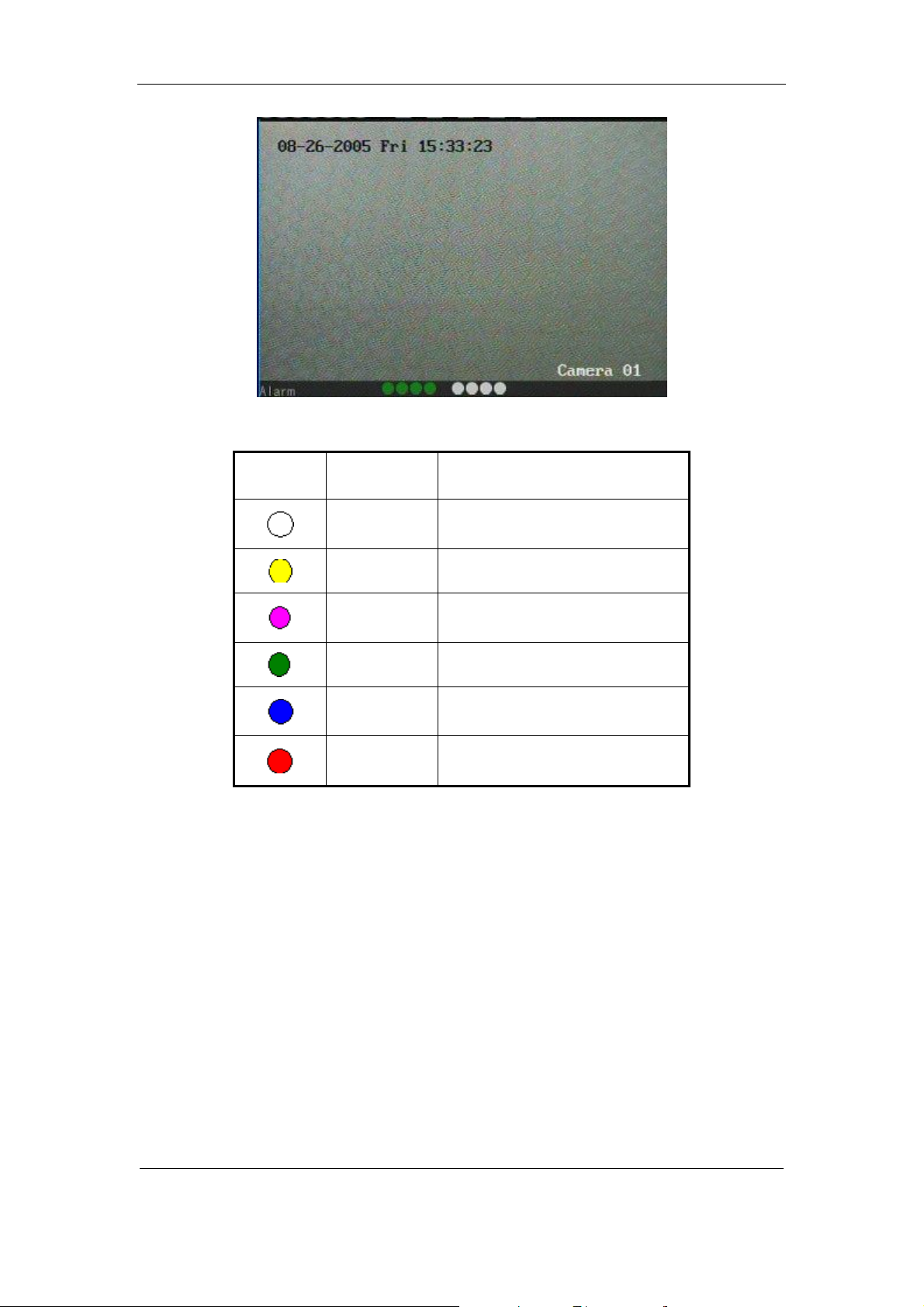
4.2 Preview
DVR will enter into preview mode after it is started.
On preview screen, you can see date, time, camera name and camera status icon.
Set system date and time in “Display” menu, refer to section 5.2.9; Change camera name in
“Image” menu, refer to section 5.3.2.
In the screen, it will dis play record and alarm status of each ca mera. Thes e two kinds of
status will switch over automatically.
Page 26 Total 121
Page 27

User Manual for Commercial Series Net DVR
Press【A】key to display or hide the camera status bar.
Camera record status is:
Icon Icon Color Status Description
White No video signal
Yellow Vdieo input
Pink Manual recording
Green Real time recording
Blue Motion detect r ecordin g
Red External alarm recording
Page 27 Total 121
Page 28
Camera alarm status is:
Icon Icon Color Status Description
User Manual for Commercial Series Net DVR
White Video signal lost
Yellow View tampering alarm
Pink Motion&External alarm
Green No alarm
Blue Motion alarm
Red External alarm
Press numeric keys to switch to individual camera preview. If DVR has less than 10 channels,
press one numeric key to switch corresponding channel. For example, press【2】key to preview 2nd
camera. If DVR has 10 or more than 10 channels, press two numeric keys to switch to
corresponding channel. For example, press 【0】【 2 】 to preview 2nd camera; and press 【1】
【2】keys to preview 12th camera.
Press【EDIT】key to manually cycle preview. You can set the auto preview mode in
“Preview” menu, refer to section 5.11.
Press【PREV】key to switch multi-screen perview.
Page 28 Total 121
Page 29
User Manual for Commercial Series Net DVR
4.3 User name and password
Note: When DVR is delivered from factory, there is only one default administrator
named “admin”, and password is “12345”. The administrator ’s name can not be modified,
while the password can be modified. The administrator can create 15 users and define their
user rights.
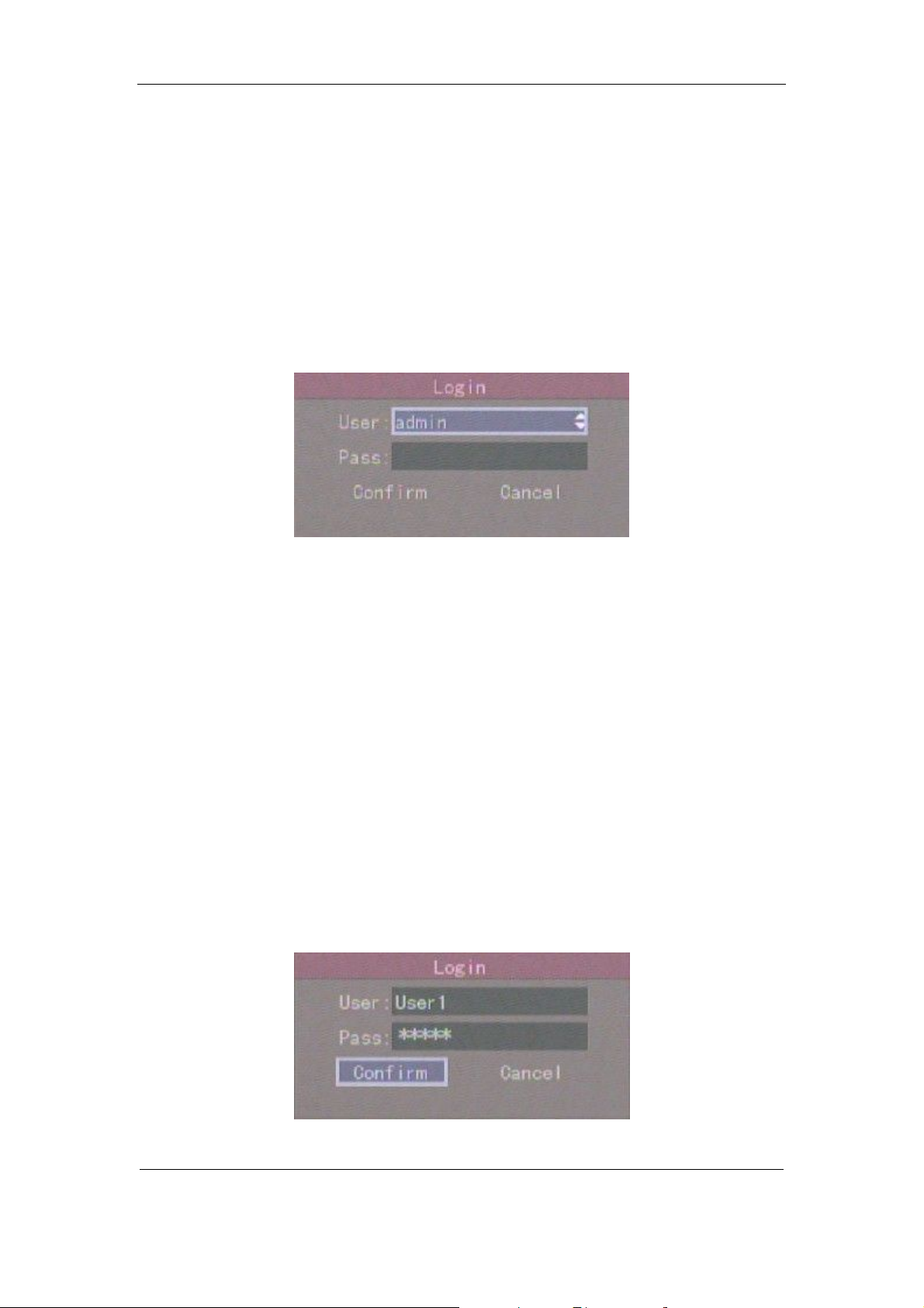
Login
Login dialog box:
Use【á】/【â】keys to sel ect one user, perss【à】key to enter into “Password” edit box, input
corr espon di n g passw ord, pr es s【ENTER】key to exit edit box. The “Active Frame” will be moved
to “Confirm” button. Press【ENTER】key to enter into main menu. If there is beeper alarm, it
means the user name a nd passw ord do not match. After three inc orrect trys the D VR wil l enter
into previ ew mode.
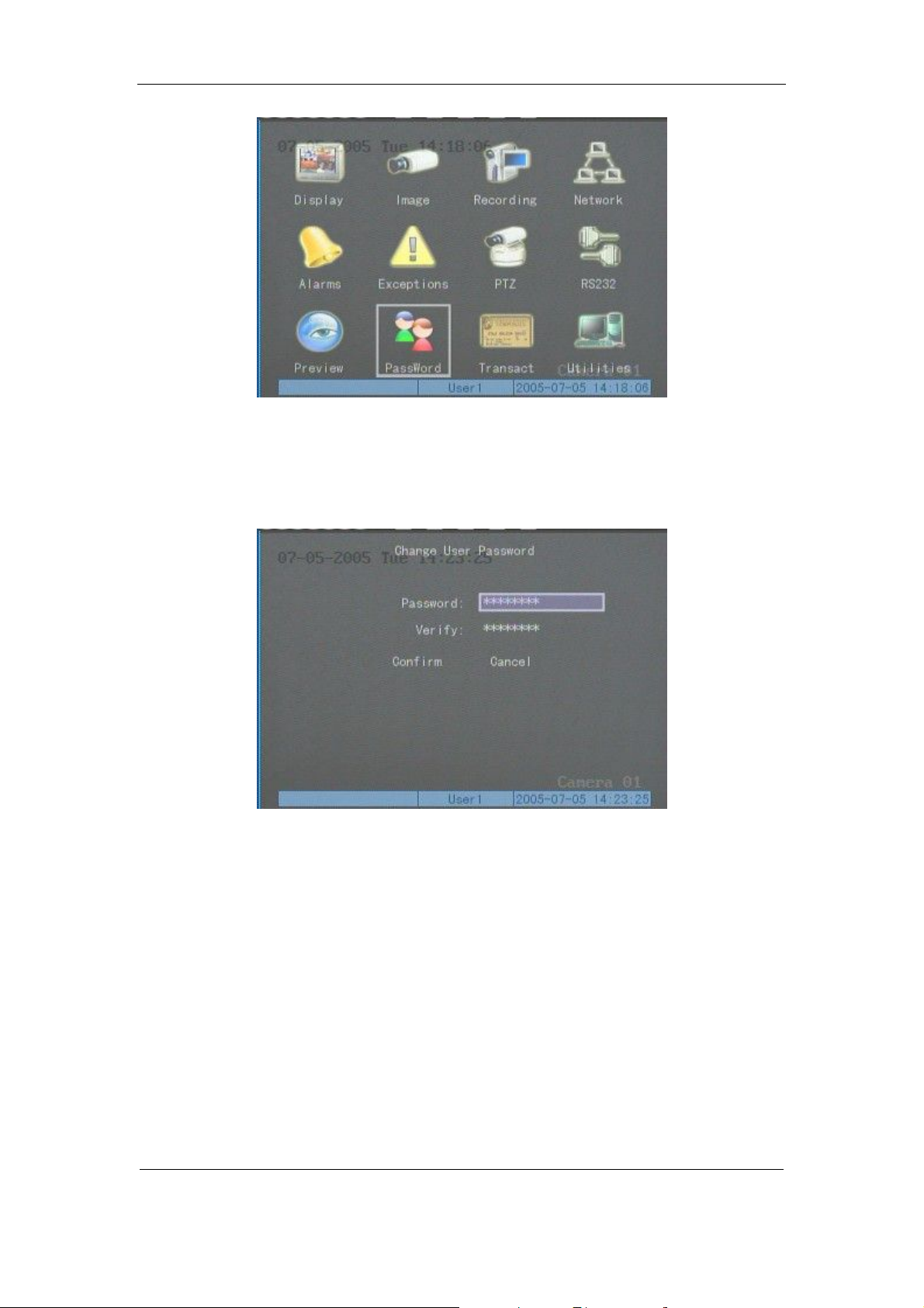
Modify password
For those users created by admin, they can modify their password as follows:
Step1: Enter into main menu
Press【MENU】key, in the logi n dialog, s elect your user name, i nput t he cor rect password, you
can e nter into t he main menu.
Page 29 Total 121
Page 30
User Manual for Commercial Series Net DVR
Setp 2: Enter into password modification menu
Move the “Active Frame” to “Password” icon by using【à】/【ß】keys. Press【ENTER】
key t o enter into password menu:
Step 3: Input new password
Press【EDIT】k ey t o ent er i nt o e dit b ox. You can use n umer ic ke ys t o i npu t new pa ssw or d.
The password can be null. It also can be 16 numerals. Press【ENTER】to exit edit box, and move to
“Verify” ite m to inpu t t he new pa ss w or d for ver if i ca ti on.
Note: In edit box, use 【à】/【ß】to move cursor and【EDIT】key to delete the numeral
in front of the cursor.
Step 4: Modify password successfully
Move the “Active Frame” to “Confirm” button, press【ENTER】key. If the password is
Page 30 Total 121
Page 31

User Manual for Commercial Series Net DVR
modif ied succ essf ully, you wi ll get t he main menu or an error dialo g box will pop up. You can
repeat step 3 to modify again.
4.4 PTZ Control
Note: The user must have the “PTZ control” right.
PTZ control interface
In pre view mo de, pr ess【PTZ】key, in t he logi n dia lo g, s elec t one user na me and i nput t he
correct password, you can enter into PTZ control interface.
In menu mode, press【PTZ】key, you can enter into PTZ control interface directly.
There is “ PTZ Co ntrol” pr ompt in t he PTZ c ontrol interface. The displaye d camera na me
shows which channel’s PTZ is under control. For example, “Camera 01” means you are
controlling the 1st camera PTZ.
Select channel
In PTZ control mode, you can press numeric keys to select channel. If DVR has less than 10
channels, press one numeric key to select. For example, press【2】key to select 2nd camera PTZ. If
DVR has 10 or more than 10 channels, you must press two numeric keys to select. For
example, press【0】【 2 】 to select 2nd camera PTZ, and press【1】【 2 】 to select 12th camera PTZ.
After you s elec t the camer a PT Z, yo u can us e the dir ecti ona l keys on th e fro nt pa nel or the
remote to control PTZ.
Page 31 Total 121
Page 32

User Manual for Commercial Series Net DVR
PTZ control keys description
Dir ec tion contr ol keys: 【↑】,【↓】,【←】,【→】;
ZOOM control keys: 【ZOOM+】,【ZOOM-】;
FOCUS control keys: 【FOCUS+】,【FOCUS-】;
IRIS control keys: 【IRIS+】,【IR IS-】;
Adju st pr eset ke ys : 【REC/SHOT】;
Auto control key: 【PLAY/AUTO】;
Wiper co ntrol key: 【WIPER/MENU】;
Light control key: 【LIGHT/F1 】;
Auxiliary device control key:【AUX/F2】
Adjust preset description
In PTZ c ontr ol mod e, pres s【REC/SHOT】key, and pres s the pres et number ( thre e numeric
keys), DVR will adjust the corresponding preset number. Repeat pressing【REC/SHOT】key, and
press the preset number, DVR will adjust that preset number.
When you exit PTZ control mode, the camera will stay at the current position.
Note: The P TZ preset nu mber is set alr eady. Plea se refer to PTZ menu for pr eset setup. C urrent
firmware can support 128 preset number at most.
Start/Stop auto in PTZ control mode
In PTZ control mode, press【 PLAY/AUTO】 key to start PTZ auto function. Press
【PLAY/AUTO】key again to stop.
When PTZ is in auto mode, if you exit PTZ control mode, PTZ will continue auto
function.You must enter into PTZ control mode again, and press【PLAY/AUTO】key to stop.
Exit PTZ control mode
Press【ESC】or【ENTER】to exit and return to preview mode.
Page 32 Total 121
Page 33

User Manual for Commercial Series Net DVR
4.5 Manual Record
Note: The user must have the corresponding right, DVR must have HDD and HDD must be
formatted.
Manual record
In pre view mod e, pr ess【REC】key, in the pop-up login dialog, select the name and input the
corr ec t passw ord, yo u ca n t he n e nt er into the “Manual Record” i nt erface .
In menu mode, press【REC】key to enter into “Manual Record” interface directly.
Description
Manual record interface has following parts: channel number, channel status, start/stop record,
start all and stop all buttons.
Channel: Lists the channel numbers that the DVR has.
Status: Channel work status has 4 cases:
means idle. Green means the channel is
recordi ng (in cluding r eal time recor ding, ala rm recording, motion detect ion recording). Red means
netw or k tramsmi s sion. Or a nge means b ot h recordi n g an d net w or k tra nsmis sion.
Start/Stop: “ü” means you can st art cor respon ding cha nnel rec ording. “×” menas you can
stop recor ding.
S tart All: Press this button to start all channels recording.
S top All: Press this button to stop all channels recording.
Exit manual record
Press【ESC】key to enter into preview mode. Press【MENU】key to enter into main menu.
Page 33 Total 121
Page 34

User Manual for Commercial Series Net DVR
Press【PLAY】key to enter into playback menu. Press【PTZ】key to enter into PTZ control mode.
4.6 Playback
Note: The user must have “Playback” right.
Playback interface
In pre view mode , pres s【PLAY】 key, in t he po p-u p lo gi n dia lo g, s ele ct userna me a nd i npu t
corr ect pass word, yo u ca n ent er i nto “Pl a yb a ck” i nt er face.
In menu mode, press【PLAY】key, you can enter into “Playback” interface directly.
One Channel Playback
Two Channel Playback
Page 34 Total 121
Page 35

User Manual for Commercial Series Net DVR
Description
If DVR only supports one channel playback, you can not select second channel. If DVR can
support two channel playback, you can select second channel.
Main Channel: Use【↑】or【↓】key to select one channel.
Second: If DVR supports 2-ch playback, you can use【↑】or【↓】key to select the second channel.
These tw o cha n nels ca n be pla ye d ba ck s i mult ane ous l y. If yo u sel e ct t he s ec ond c ha nn el a s no ne,
only the ma in channel is played back.
Rec Type: Use【↑】or【↓】to select recorded files type. The file type options have “All”, “All
Time”, “Motion Detect”, “Alarm” and “Manual”.
Time Section: You can de fi ne the s ea r ch ti me section. M ove “ Active Fra me” to t he ti me e dit
box, use numeric keys to input the detail time.
Card Number: DVR can get text number through RS-232 or network port. The text is sent
from devices such as ATM machine, POS machine or others. DVR can overlay the text on the real
time i ma ge a n d rec or d. You ca n us e t he t ext to s ea r ch t he r ecor de d fi le s a nd pl ay t h em b ack. Us e
the numeric keys to input the text number.
Search: Se arch the matched r ecorde d files and dis play the m in the li st box. I f there is no
matched file, a corresponding dialog box will be pop-up.
Play by Time: Playback the recorded stream directly based on the time section.
Select Page: In the file list box, each page will only display 8 fi les. If the matched files are
more than 8, you can select page to list other files. 500 pages (4000 files) can be searched at one
time. You can use numeri c keys or 【↑】【↓】keys to select page.
File List Box: Lists the matched f iles. File started time, file size a re displayed in the list
box.You can use【↑】【↓】keys to move the scroll bar to select file.
Backup Devices: You can select USB flash, USB HDD, USB DVDRW/CDRW, SATA
DVDRW/CDRW or SATA HDD to backup the files or clips.
Copy: Start to backup.
Backup Today: Backup all recorded files from today.
Page 35 Total 121
Page 36

User Manual for Commercial Series Net DVR
Three kinds of playback mode
1. Search and playbck file: In the playback interface, you can select main channel, second
cha nnel (2 -c h pla yba c k), rec or d t yp e, ti me s ect i on. M ove “ Ac tive Fr a me” t o “ Se a rch” b utt on a n d
press【ENTER】key, DVR will search and list the matched files.
If th e mat che d fil es a re more tha n 8, you ca n us e “ Page No. ” to s ele ct pa ge ( us e nu meri c ke ys or
【↑】【↓】keys to select page). In the file list box, use【↑】【↓】keys to move the scroll bar to the
file, press【ENTER】key to playback the file. If the second channel is selected, these two channels
can be played back simultaneously
.
If DVR can not find the matched files, a failure dialog box will pop-up.
2. Playback by Time: In the playback interface, select main channel, second channel (2-ch
playback), record type and time section, move “Active Frame” to “Play” button, press【ENTER】
key, DVR will start to playback based on time section.
3. Search by Card No and Playback file: In the playb ack i nterfac e, sel ect ma in c hannel,
second channel (2-ch playback), record type, enable card No. search option (“ü”) and inp ut the
card number, move “Active Frame” to “Search” button, press【ENTER】key, DVR will search and
list the matched files. If the matched files are more than 8, you can use numeric keys or【↑】【↓】
keys to select page. Use【↑】【↓】keys to move scroll bar to the file, press【ENTER】key to playback
the selected file. If DVR can not find any matched files, a message dialog box will pop-up.
Page 36 Total 121
Page 37

User Manual for Commercial Series Net DVR
Operation when playing back
Playback picture:
One Channel Playback
Two Channel Playback
At the bottom of the image, there is an information bar with the following information:
Volume, Play Progress, Play Speed, Played Time and File Total Time.
l Display/Hide information bar: 【MENU】
l Open/Close sound: 【PLAY】
l Adjust play progress: 【←】(Backward),【→】(Forward). The un it is “%”.
l Adjust play speed: Normal speed is “1x”. Use 【↑】to increase play speed ( 2X, 4X,
Page 37 Total 121
Page 38

User Manual for Commercial Series Net DVR
8X and MAX). Use【↓】to decrease play speed (1/2X, 1/4X, 1/8X and Frame by
Frame)
l Pause/Continue: Press 【ENTER】to pause/ c o nti n ue pl a yba ck. If pla y ed fra me by
frame, Press【ENTER】to display one frame.
l Copy segment:【EDIT】
l Exit: 【ESC】
l Pla yba ck swi tch : Whe n in 2- ch pl ayba ck, press 【PREV】to s wit ch b et wee n main
channel and second channel.
Note: When DVR is busy, if you select high play speed, t here may be a difference from
actual play speed.
Exit playback
In playback interfa ce , pres s【ESC】key t o enter into preview mo de.
In playback interfa ce , pres s【MENU】key to enter i nto main menu, press【REC】key to enter
into manua l record, and press【PTZ】key to enter into PTZ control mode.
Page 38 Total 121
Page 39

User Manual for Commercial Series Net DVR
4.7 Backup Recorded Files
Note: The user must have “Playback” right. Please connect with backup devices before
you start to backup.
In the playback interface, you can backup the recorded files.
In the preview mode, press【PLAY】 key, in t h e login di a l og box , select user name and i n p ut
the c orrect password, you can ent er into the pl ayback interface.
In the menu mode, just press【PLAY】 key, you can enter i nt o pla yba c k inter fa c e dir ect l y.
Record Daily Backup
In the playback interface, move “Active Frame” to “Backup Today” button, press【ENTER】
key, all r ecor ded f iles of al l cha nnels for the da y wil l be b acke d up t o the sa ve devic e. A pop- up
dialog box will display the backup status.
If backup device is not connected correctly or DVR does not detect the backup device, the
following dialog box will pop-up. Please ask administrator for more information.
Backup the files that you selected
Step 1: Search the matched files
In the playba ck interface, select one chan nel and recor d type, input the ti me section, move
“Active Frame” to “Search” button, press【ENTER】key, DVR will start to find and list the
matched files.
Page 39 Total 121
Page 40

User Manual for Commercial Series Net DVR
Step 2: Select the files that you want to backup
In the file list box, use【↑】or【↓】keys to move the scroll bar. When the scroll bar stays at the
file you want to backup, press【EDIT】key to select it. The symbol “ü” is the selection tag. You
can us e t he sa me me t hod t o sel ect ot her fi les yo u wa nt to ba ckup. Af ter fi nis hin g, you ca n d o the
next step.
Step 3: Select backup device
Please select the backup device: USB flash memory, USB HDD, USB DVDRW/CDRW,
SATA DVDRW/CDRW, or SATA HDD.
Step 4: Start and finish backup
Move “Active Frame” to “Save” button and press【ENTER】key to start backup.
When backup is started, corresponding message box will pop-up to indicate the result.
Backup video segment
You also can backup the image segments when the image is being playback. The steps are:
1) Enter into the interface of playback the fil es or playback by time;
2) Press【EDIT】key to start selecting the current playback images, and press【EDIT】again
to stop selecting. This segment is selected;
3) You can repeat step 2 to select many segments. 30 segments can be selected in all;
4) After you select all segments, press【ESC 】key, a message window will pop-up. If you
press “Confirm” button, DVR will start to backup the selected segments. If you press
“Cancel” button, DVR will abort backup.
Page 40 Total 121
Page 41

User Manual for Commercial Series Net DVR
Note: The backup function is effective when two channels are played back simultaneously. In such
case, each channel can backup 30 segments so 60 segments can be backed up for two channels.
Playback the video segment
You can use our fil e pla yer soft wa re to pl ayba ck t he v ide o seg ment i n PC. You can fin d the
player software on the included CD.
Exit playback interface
Please refer to chapter 4.6.
4.8 Shut Down DVR
Note: Do not switch off the power directly in case of damaging HDD. The correct step is
using “Power Off” in the “Utilities” menu, or【POWER】key on the front panel or on IR
controller.
Shut down DVR normally
Use menu
Enter into “Utilities” menu, move “Active Frame” to “Power Off” button and enter into
power off dialog box, press “Confirm” to shut down the DVR.
Use【POWER】key of front panel or IR controller
Press【POWER】key for 3 seconds.
In pre vi ew mod e , a l ogi n di a l og b ox wi l l p o p- up, s e l ec t u ser name a nd i n put pa s sw or d, pr es s
【Enter】to ent er i nt o po we r o ff dia log box and pr es s “Co nfi rm” to s h ut d ow n D VR. If yo u i np ut
incor r ect passw ord thr ee ti me s, D VR wi ll return pr e vie w mod e.
In menu mode, if the user has “Utilities” right, you can enter into power off dialog box, press
Page 41 Total 121
Page 42

User Manual for Commercial Series Net DVR
“Confirm” to shut down DVR. Otherwise, the user can not shut down DVR.
If DVR is shut down correctly, the【POWER】lamp is on red.
Note: When me ssage of “Shut down…” has appea red, plea se do not press【POWER】key any
more, otherwise, DVR can not be shut down.
Abnormally Shutting down DVR
Using the power switch on rear panel
When DVR is running, if you switch off the power, the HDD in DVR may be damaged.
Please avoid such operation.
Taking away the power cable
Please avoid taking away the power cable directly.
Note: In some cases, when the power supply is abnormal, DVR will be damaged. We suggest
that you use recommended power supplies.
Page 42 Total 121
Page 43

User Manual for Commercial Series Net DVR
Chapter 5 Main and Aux Output Function
5.1 Main and aux output
QSC26408, and QSC26416 Commercial series DVRs have one main output and one aux
output.
You can use mai n vi deo out put to enter into DVR men u a s f ollows, while aux output can not
display DVR menu.
The aux output can support DVR local preview, local playback and local PTZ control. Press
【Mai n/A ux 】 button to switch between “Main” output and “Aux” output control mode.
Page 43 Total 121
Page 44

User Manual for Commercial Series Net DVR
5.2 Main and Aux output preview
You can use “Main” output to enter into DVR menu, setup both “Main” and “Aux” output
preview proper t ies.
Please press 【Main/A ux】 button to enter into “Main” output control mode, then press
【Menu】 button to enter into DVR menu, the main video output will display the following DVR
menu:
Move “Active Frame” to “Preview” icon and press【ENTER】to enter into “Preview” menu:
You can sel ect out t o setup ma in output and aux output respecti vely.
Page 44 Total 121
Page 45

User Manual for Commercial Series Net DVR
Preview mode: For preview mode item, you can use【↑】【↓】key to select one mode. If DVR
has o nly 1 channel , y ou can s elect onl y “1 Sc reen” opti on. If D VR ha s 4 cha nnel s, ther e ar e “1
Scree n” a nd “4 Scree n” opt ions. If DVR has more t han 4 but les s t han 9 c hann els, t here a re “ 1
Screen”, “4 Screen” a nd “9 Screen” options. I f DVR has 16 channels, ther e are “ 1 Screen”, “4
Screen”, “9 Screen” “12 Screen” and “16 Screen” options.
Switch time: That is image preview switch time. You can use【↑】【↓】keys to select switch
time. There are many options, including “5 Seconds”, “10 Seconds”, “20 Seconds”, “30 Seconds”,
“60 seconds”, “120 seconds”, “600 seconds” and “Never”. If you select “Never”, the preview
image will not be switched automatically. For example, for 16 channels DVR, if you select “4
Screen” preview mode and “20 Seconds” switch time, DVR will cycle display 4 channel image
every 20 seconds.
Audio preview: If y ou e nab le a udi o pre vie w (“ü” ) , whe n y ou pre vie w si n gle camer a , D VR
will play the audio of that channel.
Preview layout setup: There i s a sq uar e fr a me di vide d i nt o ma ny wi nd ows . I f y ou sel e ct “ 4
Screen”pr eview mode, this fra me i s divid ed int o 4 wind o ws . E a ch wind ow r e prese nt s o ne c amer a .
You can move “Active Frame” among the windows. There is one bar under the square to display
the preview order of all cameras.
First sel ect the biggest screen preview mode, for exa mple, for 16- channel DVR, sel ect “16
Screen” preview mode so that all windows are display in the square.
Secondly, move “Active Frame” to one of these windows, press numeric keys to input
camera index (If DVR has less than 10 channels, just use one numeric key, otherwise, use 2
numeric keys). The s mall wi ndow will displa y tha t ca mera nu mber. In t his wa y yo u can c hange
the display order. If you press 0 or 00, then the corresponding window will not display live video.
Page 45 Total 121
Page 46

User Manual for Commercial Series Net DVR
After you define the camera preview order, you can select preview mode to meet your
demand.
Save setup: Press “Confirm” button to save preview configuration. Press “Cancel” or
【ESC】key to abort.
Whet her in “ Mai n” or “ Aux ” out put contr ol mod e, y ou c an pr ess 【PREV】butto n t o e nter
into live preview and cha nge preview screen mode.
Page 46 Total 121
Page 47

User Manual for Commercial Series Net DVR
5.3 Main and Aux output playback
Both “Main” and “Aux” output can be used to playback the recorded files on DVR HDD.
Press 【Main/Aux】button to enter into “Main” or “Aux” control mode, and press 【PLAY】button
to ent er into “ Playb ack” men u. You ca n use “ Main” out put to pl aybac k one cha nnel and “ Aux”
output to playback another channel at the same time.
Page 47 Total 121
Page 48

User Manual for Commercial Series Net DVR
5.4 Main or Aux output to control PTZ
You can press 【Main/Aux】 button to enter into “Main” or “Aux” output control mode and
press 【PTZ】button to control one PTZ.
Please note if you enter into “PTZ” control mode, 【Main/Aux】button is not effective until
you press 【ESC】button to exit PTZ control mode.
Only the users that have “Para meters Set up” right need read this chapt er. When the following
parameters are modified and saved, you must reboot the DVR to make the new parameters
effective. Other parameters do not require you to reboot.
Page 48 Total 121
Page 49

User Manual for Commercial Series Net DVR
Chapter 6 Parameters Setup Guide
Only the users that have “Para meters Set up” right need read this chapt er. When the following
parameters are modified and saved, you must reboot the DVR to make the new parameters
effective. Other par ameters do not need to r eboot.
l Any network para meters
l Stream type, resolution and record schedule
l External alarm sensor type
l View tampering alarm schedule
l Video lost alarm schedule
l Motion detec tion alarm schedul e
l External alarm schedule
l Alarm output schedule
l Transaction
l RS232 work mode
l Change video output standard
6.1 Administrator and Password
When the DVR leaves the factory, there is one default administrator. The name is “admin”
and password is “12345”. The name can not be changed, while the password can be.
Password modification
Press【MENU】key, in t he l o gi n dia l og b ox, sel ect th e us er na me “ ad min” , us e 【→】key, to
move cursor to passwor d edit box, i nput “12345”, pr ess “Confirm” to e nter into administra tor
menu.
Page 49 Total 121
Page 50

User Manual for Commercial Series Net DVR
Move “Active Frame” to “User” icon, press【ENTER】key to enter into “User M anagement”
menu.
In the user name list box, only “admin” exists. You can use【→】key, move “Active Frame” to
password edit box, and press【EDIT】key to enter into edit status. Press numeric keys to input the
new pa ss wor d. T he pa ss wor d is a c ombi na tio n of 1 6 numer a ls a t most . Aft er yo u fini s h i nput ti ng
pass w or d, press【ENTER】key to exit. Move “Active Frame” to “Verify password” edit box, input
the new password. Move “ Active Frame” to “Confirm” button, and press【ENTER】, if new
password and verified new password are the same, the password will be saved and take effect.
If password and verified password are not same, a warning message box will open.
In this case, press【ENTER】to ret ur n to pa s s word edit box, a nd i npu t ne w pa s sw ord aga in.
Page 50 Total 121
Page 51

User Manual for Commercial Series Net DVR
6.2 Add and Delete User
Enter into “User Management” interface.
Add user
The steps are as follows:
Step 1: Enter into “User Management” menu
Please refer to chapter 5.1
Step 2: Add new user name
In the “User Management” menu, move “Active Frame” to “Add” button and press
【ENTER】, in the pop-up dialog box, input the new user name (refer to chapter 3.4), press
【ENTER】and return “User Management” menu. 15 users can be added in all.
Step 3: Setup the password for new user
After yo u a dd a new user, t he pa sswor d is n ull. You ca n s ki p thi s st ep if yo u do n ot wa nt to
cha nge the passwor d.
Page 51 Total 121
Page 52

User Manual for Commercial Series Net DVR
In the users list box of “User Management” menu, use【á】【 â 】 keys to select the new user
name, t he n us e 【à】key t o t h e pa s sw or d e di t b ox . P r ess【EDIT】ke y t o e nt er i nto e dit box, use
numeric keys to input the new password.
Step 3: Setup the rights for new user
The new added user has not any operational rights. You must setup rights for him.
In the users list box of “User Management” menu, use【á】【 â 】 keys to select the new user
name, then use【à】key to “Default Rights” but ton, press【ENTER】, the user wil l hav e the default
rights. The default rights include local playback, remote playback and view log.
If yo u want to de fine t he det ail ri ghts, move “ Acti ve Fra me” t o “Setu p Right s” b utton a nd
press【ENTER】to enter into rights setup menu as follows:
Operational rights are divided into “Local Rights” and “Remote Rights”. You can assign the
necessary rights to the user. Use【à】【 ß 】 key to move “Active Frame” to the corresponding right
items, press【ENTER】or【EDIT】key to enable or disable the item. “ü” means ass igning the right
to that user.
After you fi nish, pr ess “E nter” butto n, the us er’s r ights will be sav ed and r eturn t o “User
Management” menu. If you press “Cancel” button, the user’s rights will be aborted.
Step 4: Save the new user’s password and rights
In t he “User Management” me nu, pres s “Con firm” b utton, t he user ’s pass word an d rights
will b e s a v e d a nd y o u wi l l r et urn t o ma i n me nu. I f y o u pr ess “ Ca nce l” b ut t o n, t he us er’s pa s s word
and rights will be aborted.
Page 52 Total 121
Page 53

User Manual for Commercial Series Net DVR
User rights d escription
“Local Rights”:
Loca l r i g hts a re for local oper atio n, s u c h a s t he o per a t i o n us ing front panel, I R cont r ol l er and
RS-485 keyboard.
PTZ control: Locally control PTZ;
Record: Manual start/stop recording;
Playback: Local playback and backup the recorded files;
Para meters Setup: Loca ll y setup the DVR parameter s;
Log: Locally view the log on DVR;
Utilities: Locally upgrade firmware, format HDD, reboot DVR and shut down DVR, etc.
“Remote Rights”:
PTZ Control: Remote control PTZ;
Record: Remote manual start/stop recording;
Playback: Remote playba ck, do wnload the recorded fi l es on DVR ;
Parameters Setup: Remotely setup the DVR parameters;
Log: Remotely view the log on DVR;
Utilities: Remotely upgrade firmware, format HDD, reboot DVR and shut down DVR, etc.
Voice: Client talks with DVR;
Previ ew: Net wor k live previ ew;
Alarm: Remote control DVR ala r m output;
Local Video Out: Remote control DVR video output;
Com Control: DVR RS-232 transparent channel function.
MAC address
This MAC address is not the address of DVR but the PC that will access DVR. If you setup
this MAC address, only the PC with this MAC address can access this DVR.
At PC end, in DO S pro mpt , y o u can us e “ipc o nfig” c o m ma n d to get t he PC MAC a ddress ( 6
bytes).
Delete user
In “User Ma nageme nt” interfa ce, you ca n use【á】【 â 】 ke ys to select one user, then use【à】,
move “Acti ve Fra me” to “ D el” butt on, press 【ENTER】, in the pop-up confirmation dialog box,
press “ Confir m” b utto n to de let e the s ele cte d user and r etur n. Pr ess “Ca ncel ” or 【ESC 】to abort
deleting.
Page 53 Total 121
Page 54

User Manual for Commercial Series Net DVR
6.3 Unit Name and Device ID
Uni t name
In the “Displa y” menu:
There is an item called “Unit Name”. The default unit name is “Embedded Net DVR”. Move
“Active Frame” to unit name edit box, press【EDIT】key to enter into edit status, you can modify
the unit name. For instructions on how to input characters, please refer to chapter 3.4. Press
【ENTER】key to finish modification. Select “Confirm” button and press【ENTER】, you can save
the new unit name and make it take effect. Press “Cancel” button or【ESC】key to abort
modification.
Device ID:
When y ou use I R contr oller t o oper ate DVR, you mus t use d evice ID to selec t DVR. The
default device ID of the DVR is “88”. If there is more than one DVR in one place, please set a
different device ID for each DVR. Otherwise, the IR controller will control all DVRs with the
same device ID at the same time.
In “Display” menu, move “Active Frame” to the device ID edit box, in the edit status, you
can use numeric keys to input a new device ID. The device ID can be set between 01-100.
After you finish t he modifi catio n, press “ Confir m” b utton t o save a nd take effect or press
“Cancel” to abort modification.
Page 54 Total 121
Page 55

User Manual for Commercial Series Net DVR
6.4 Video Output Standard and VGA Setup
Video output standard
There is one VOUT BNC connector at the rear panel of DVR. It is used to connect with an
analog monitor and can support PAL or NTSC video output. You can modify video output
sta ndard to match vi deo input.
In “Displ ay” menu :
There is a list box called “Video Standard”, you can use【á】【 â 】 key to select PAL or NTSC
vide o outp ut.
VGA setup
There is one VGA interface on the rear panel of DVR. You can use it to connect with a VGA
displ ay. You can defi n e VGA res oluti o n an d r e fresh freq u en cy in “D i s play” me nu.
There are three options: 1024*768/60Hz, 800*600/60Hz and 800*600/75Hz. You can use
【á】【 â 】 key to select.
Press “Confirm” button to save or “Cancel” to abort.
Page 55 Total 121
Page 56

User Manual for Commercial Series Net DVR
6.5 OSD Setup
OSD is an a bbreviation for “On Screen Display”. For our embedded net DVR models it
includes displaying system time and camera name.
OSD settings include: System time, time format, time display position, camera na me, camera
name dis play posi ti on, etc.
System Time
In “Di s pla y” me nu, y o u ca n set u p DVR s ys t e m date a nd time.
Display System Time
You can setup display properties for each camera, including display status, position and
format. Of course, you can copy the properties of one camera to another camera or to all cameras.
In “Image Setup” menu select one camera :
Page 56 Total 121
Page 57

User Manual for Commercial Series Net DVR
Display mode: There are several display modes: Opaque&Steady, Transparent&Steady,
Transpa rent &Fla shin g, Opa que& Flas hin g,
Move “Active Frame” to “OSD” item, you can select one mode.
Display position and format: Move “Active Frame” to “Position” button on the right side of
“OSD”, press 【ENTER】to enter into setup image, there are 22*18 (for NTSC, 22*15) small
panes, and OSD position i s in red . You can use【â】【 á 】【 à 】【 ß 】 keys to move the OSD position.
Press【EDIT】key to select OSD format. There are following OSD formats:
MM DD YYYY W hh:mm:ss (default)
MM DD Y YYY hh:mm: ss
YYYY MM DD W hh:mm:ss
YYYY MM DD hh:mm:ss
Here YYYY means year, MM means month, DD means day, W means weekday, hh menas
hour, mm means minute and ss means second.
Press【ENTER】 to save and retur n to “ Ima ge” me nu or pr es s【ESC】to ab ort modification.
Copy parameters: After you setup the properties of one camera, you can copy it’s parameter
to any other camera or all cameras.
After you sa ve t he modifi cat ion, i t wil l bec ome e ffec tive . You can pr ess “ Ca ncel” b utto n or
【ESC】key to abort.
Camera Name
In “Image Setup” menu, you can define name for each camera. Please note that camera’s
name can not be copied.
Page 57 Total 121
Page 58

User Manual for Commercial Series Net DVR
The steps for camera name setup:
Step 1: Select one camera.
Step 2: Move “ Active Fra me” to camera na me edit b ox, p r ess 【EDIT】ke y to enter i nto edi t
status, you can input digital number, uppercase and lowercase characters (refer to Chapter 3.4).
The camera name can s upport 32 characters.
Step 3: Press【ENTER】key to exit edit status.
Move “Active Frame” to “Confirm” button, press【ENTER】to save the modification and you
can see the new camera name. Press “Cancel” button or【ESC】key to abort.
Setup Camera Name Position
If you do not want to display camera name, just disable the check box beside camera name
edit box. The disable flag is “×”. If you enable the check box, you can setup the camera name
position. You can copy the position to any other camera. The setup steps are:
Step 1: Enter into “Ima ge Setup” menu.
Step 2: Select one camera.
Step 3: Enable the check box on the right side of camera name, then move “Active Frame” to
“Position” button, press【ENTER】to enter into camera name position setup interface, in that
interface , y ou can use【â】【 á 】【 à 】【 ß 】 keys to move camera name position. When the position
is fixed, press【ENTER】and return “Image Se tup” menu, and press “Con firm” button to save i t. In
the “ Image Setup” men u, press “ Cancel ” button or【ESC】key, to abort the modification.
Page 58 Total 121
Page 59

User Manual for Commercial Series Net DVR
6.6 Video Parameters Setup
For di fferent camer as and di fferent b ackgr ounds, i n order to get t he best video i mage, y ou
may need to adjus t video para meters such as brightens s, satur ation, contrast and hue, etc.
You can setup the cameras individually, and you can copy the video parameters of one
camera to any other cameras. Here are the setup steps:
Step 1: Enter into “Image Setup” menu:
S tep 2: Selec t camera: Please use【á】【 â 】 keys to sel ect one camera.
Step 3: Adjust brightness, contrast, saturation and hue: Move “Active Frame” to the
“Adj ust ” butt o n on the r i ght si de o f Br i ght n ess , Co nt ra s t, Sa tur a ti on a nd H ue, pr es s 【ENTER】
key, you will ent er int o the cor respon ding adjust int erface. In the a djust i nterface , ther e is one
scroll bar at the bottom, you can use【á】【 â 】 keys to adjust and the video image will be changed
at the same time. When you are satisfied with the real time video image, press【ENTER】to return
“Image Setup” menu.
Step 4: You can co py the video para meters of the c urrent camer a to an y oth er ca meras. Or
you can re peat setp2 and step3 to adjust for any other camera.
After adj ust, i n “I mage Set up” menu, press “ Confi rm” b utto n to sa ve pa ramet ers a nd ma ke
them effective. Otherwise, perss “Cancel” button or【ESC】key to abort modification.
Page 59 Total 121
Page 60

User Manual for Commercial Series Net DVR
6.7 Mask Area Setup
In some cases, you may want to mask a sensiti ve area. This a rea will not be previ ewed or
recorded. The mask area setup steps are following:
Step 1: Enter into “Image Setup” menu:
Step 2: Select a camera: You can use【á】【 â 】 keys to select the camera.
Step 3: Enter into mask area setup interface: Enable the check box beside “Privacy Mask”,
you can pres s【E D IT】key to change the flag into “ü”, and activate “Area” button. Move “Active
Frame” to “Area” button on the right side of mask check box, press【ENTER】key to enter into
mask area setup interface.
Page 60 Total 121
Page 61

User Manual for Commercial Series Net DVR
Step 4: Setup mask area: In the mask area setup interface, there is one small yellow pane on
the upper left side. For PAL camera, the whole screen is divided into 22*18 panes (22*15 for
NTSC), you can use【↑】【↓】【→】【←】keys to move the yellow pane to your desired position and
press【EDIT】key, the yellow pane will be turned into red, then you can use【↑】【↓】【→】【←】
keys to extend the red pane. This red area is the mask area.
After you s ele ct t he red mask ar ea , pr ess 【EDIT】key to save the mask area. Press【ESC】
key to cancel the mask area. The maximum mask area size is 8*8 panes and the minimum size is
only one pane. You can setup 4 mask areas at most.
After y ou fi ni s h se tup, pr es s【ENTER】key t o r etur n t o “Imag e S etup” menu. You ca n pr es s
【A】key to clear all mask areas.
Step 5: Save mask area: You can r e pea t s t ep2, st e p3 a n d ste p4 t o s et up mas k a rea for ot her
ca meras. In “I mage Set up” menu, pr ess “ Confi rm” b utto n to sav e the mask a rea , press “ Ca ncel”
button to abort.
Here is an example of the mask area function.
If you disable the mask check box, you can cancel the mask area.
Page 61 Total 121
Page 62

User Manual for Commercial Series Net DVR
6.8 View Tampering Alarm
If you enable this function, when someone blocks the camera spitefully, DVR will transmit a
warning alar m.
Step 1: Enter into “Image Setup” menu:
S tep 2: Select camera : Please use【á】【 â 】 keys to select one camera.
Step 3: Select sensitivity: You can use【↑】【↓】keys to select the sensitivity for “ View
Tampering” item. The sensitivity options are: Low, Normal and High. Select one of them to
activate “Area Setup” and “Policy Setup” function.
Step 4: View tampering area setup: Move “Active Frame” to “Area” button, press
【ENTER】key to enter into area setup interface. The setup methods are same as that of mask area
setup. Aft er setup the area , press【ENTER】key to re turn “ Ima ge Setup” menu. You can pr ess
【ESC】key to abort.
Only one view tampering area can be setup.
Step 5: View tampering alarm setup: In “ Image Setup” menu, move “Active Frame” to
“Policy” button, pr ess【ENTER】key to enter into “View Tampering Handle” menu:
Page 62 Total 121
Page 63

User Manual for Commercial Series Net DVR
Step 6: Alarm schedule setup: When a vi ew ta mper ing al ar m occur s, t he DVR wil l han dle
the a la r m ba s e d o n t he sc he d ul e. You can s et 4 perio ds f or ea ch da y o ne w eek. Al s o you ca n c o py
the sche d ule of on e day to other da ys.
Notes: Time periods can not be repeated. Please reboot the DVR to make the setting
effective.
Step 7: Setup alarm policy: If a view tampering alarm occurs during a schedule, the DVR
will response based on the policy. You can select one or more solutions including “On Screen
Warning”, “Audible W arning”, “Upload to Center” and “Trigger Alarm Output”. You can use 【↑】
【↓】and 【EDIT】key to enable or disable them. “×” is disabled and “ü” is enabled.
Step 8: Save alarm setup: After you set up, pres s “Con firm” b utton a nd retur n to “ Image
Setup” interface. In “Image Setup” menu, press “Confirm” button to save current camera
para met er s and ret ur n to main me nu.
Step 9: Save all cameras: If you want to setup other cameras, please repeat from step 2 to
step 8. In “Image Setup” menu, press “Confirm” key to save all cameras parameters. Press
“Cancel” button or【ESC】key to abort.
Select “Off” option for “View Tampering”, you can delete the view tampering area.
Note: Onl y one vi ew ta mperi ng ar ea ca n be set up for ea ch ca mera . The view ta mper ing ar ea
can not be c opie d. If t he sc hedul e is modif ied, you must r ebo ot the D VR to make t he par a meter s
effective.
Page 63 Total 121
Page 64

User Manual for Commercial Series Net DVR
6.9 Video Loss Alarm
When t he vide o ca b le or ca mer a ha s s omet hi n g wro ng, t he vi de o i mage i s l os t. If y ou e nab le
video loss alarm, in such case, the DVR will send an alarm.
Step 1: Enter into “Image Setup” menu:
S tep 2: Selec t camera: Use 【á】【 â 】 keys to select one camera .
Step 3: Enter into “Video Signal Loss Handle” interface: Move “Active Fr ame” to the list
box o n the rig ht side o f “Video Los s” item, use【á】key to select “ Handle” option and move
“Ac ti ve Fr ame” t o t he “Policy” b ut t on on r ig ht s i de. Press 【ENTER】to enter into “Video Signal
Loss Handle” interface:
Page 64 Total 121
Page 65

User Manual for Commercial Series Net DVR
Step 4: Setup alarm schedule: You can set u p a w or ki n g schedu le. O nly w he n t he video l os s
occurs during the schedule will the DVR respond.
Note: The 4 time periods can not be repea ted. Please r eboot the DVR t o make para meters
effective.
Step 5: Setup alarm policy: You can select one or more response solutions, including “On
Scree n Warnin g”, “ Audibl e Warnin g”, “ Upload t o C ent er ” a nd “ Trigger Ala rm O utput ”. You can
use 【↑】【↓】and 【EDIT】key to enable or disable them. “×” is disabled and “ü” is enabled.
Step 6: Save alarm setup: Aft er yo ur setu p, pres s “Conf irm” butto n and r eturn t o “I mage
Setup” interface. In “Image Setup” menu, press “Confirm” button to save current camera
parameters and ret urn to main menu.
Step 7: Save all cameras: If you want to setup other cameras, please repeat from step 2 to
step 6. In “Image Setup” menu, press “Confirm” key to save all cameras parameters. Press
“Cancel” button or【ESC】key to abort.
Page 65 Total 121
Page 66

User Manual for Commercial Series Net DVR
6.10 Motion Detection Alarm
If you enable this function, when there is motion detected, DVR will make alarm.
Step 1: Enter into “Image Setup” menu:
S tep 2: Selec t camera: Use 【á】【 â 】 key to select one camera.
Step 3: Select motion detection sensitivity: On the right side of “Motion Det. Level” item,
there is a list box. That is motion detection sensitivit y. There are 7 options, from 0 (the lowest) to
5 (the highest) and “Off”. You can use【↑】【↓】keys to select one. If you select “Off” option, DVR
will n ot res p on d e ve n i f moti on is det ected. If yo u s elect other o pt i o ns , it w i ll active “ M ot io n Ar ea
Setup” button and “Policy Setup” button. If you select low sensitivity such as 0, only when there
are l arge amou nts of moti o n wi ll t he D VR r es po nd. On t he ot her s id e, f or hi gh s ens iti vi ty s uc h a s
5, the DVR will respond to small amounts of motion.
Step 4: Motion area setup: You must defi ne motio n ar eas so tha t DVR will res pons e whe n
there is motion in those areas. Move “Active Frame” to “Area” button on the right side of
sensiti vity li st box, pr ess【ENTER】key, you can enter into “Motion Area Setup” interface.
Page 66 Total 121
Page 67

User Manual for Commercial Series Net DVR
The whole screen is divided into 22*18 panes (NTSC: 22*15). There is one yellow panel on
the upper left side. The motion area setup steps are the same as that of mask area setup (refer to
chapter 5.7). The only differences are that you can use【PTZ】key to set the whole screen as motion
area, and multiple moti on areas ca n be defined. Press【A】key to clear all motion areas.
Setup multi areas: After you setup one motion area, press【EDIT】key, the yellow pane will
appear again, then you can setup another motion area.
Clear motion area:
Clear part of motion area: Move the yel l ow pane t o t he sta r t cl ea r pos iti o n of moti on a r ea ,
press【EDIT】, you will find the yellow pane is turned into black pane. You can use【↓】【→】keys
to enlarge or shrink the black area. Press【EDIT】key t o clea r this part motion area.
Press【Enter】key to save and return to “Image” menu. Press【ESC】to cancel.
Clear all motion areas: Press【A】key to clear all motion areas of this channel.
The keys used to setup moti on areas are a s follows:
l 【↑】【↓】【←】【→】: M ove yellow pa nel to any position;
l 【EDIT】:Yellow panel and re d panel switch key:;
l 【→】: Right-enlarge red panel;
l 【←】: Left-shrink red panel;
Page 67 Total 121
Page 68

User Manual for Commercial Series Net DVR
l 【↓】: Down-enla rge red panel;
l 【↑】: Up-shrink red panel;
l 【PTZ】: Set whole screen as motion area;
l 【A】: Clear all motion areas;
l 【ENTER】: Save and return to “Image Setup” menu;
l 【ESC】: Cancel setup and return to “Image Setup” menu;
The mo tion detection area is displayed as fol lows:
Step 5: Motion alarm policy: Move “Active Frame” to the corresponding “Policy” button of
motion detection alarm, press【ENTER】key to enter into “Motion Alarm Handle” menu:
Step 6: Motion alarm record channel setup: When a motion alarm happens, you can
Page 68 Total 121
Page 69

User Manual for Commercial Series Net DVR
trig ger r ela ted ca mer a to s tar t rec ordi ng. I n “ Motio n Alar m Ha ndle” men u, y ou can s ele ct on e or
more record cha nnels. Please us e【ENTER】or【EDIT】key to change the flag to “ü”.
Note: In or der to make th e camer as sta rt r ecordi ng, in “ Recor ding” menu, you must enab le
recording schedule and set “Rec Type” as “Motion Detection” or “Motion | Alarm”. Please refer to
chapter 5.12 for recording setup.
Step 7: Motion alarm schedule: When the motion occurs during a schedule, DVR will
resp ond wit h “O n Scree n War ning”, “ Audib le Warning” , “Upl oad to C enter ” or “ Trigger Alar m
Output”. You can setup 4 time periods for one day and 7 days for one week.
Note: Time per iods in one day can not be repeated.
Step 8: Motion alarm handle method setup: You ca n sel ect o ne or more ha ndle methods
such as “On Screen Warning”, “Audible Warning”, “Upload to Center” and “Trigger Alarm
Output”.
Descr ipti on: If “ On Sc ree n Warning” is e nab led, when a mo tio n ala rm ha ppe ns a nd DVR is
in pre vie w mode, DVR will dis pla y the r elat ed ca mer a. If more t han one ca mer a is t rig gere d the
DVR wi ll dis play the m one by o ne ever y 10 seco nds. W hen the motion al arm is has ende d the
DVR will return to preview mode.
Step 9: Save motion alarm setup: Pres s “Confirm” button to return “Image Setu p” menu. I n
the “Image Setup” menu, press “Confirm” button to save the current camera para meters.
Step 10: Save all cameras: You ca n repeat from ste p2 to st ep8 to set up moti on detect ion
parameters for other cameras. You can also copy the parameters of one camera to any other
camera or ca meras.
Note: Motion alarm area can not be copied.
If yo u wa nt t o di s a bl e mo t i on a la rm area a nd mo ti o n a la r m p oli c y, you j us t nee d t o s el ec t t h e
motion alarm sensitivity as “Off”.
6.11 Preview Properties
In “Previe w” menu, y o u ca n s et u p pr e vi e w mode, s cree n s wit c h time, e na b l e or dis a b l e a ud io
preview and preview layout.
Step 1: Enter into “Preview” menu: In the main men u, move “Active Fr a me” to “ Previ ew”
icon and press【ENTER】, you will enter into “preview” menu.
Page 69 Total 121
Page 70

User Manual for Commercial Series Net DVR
Step 2: Preview properties:
Preview mode: For preview mode item, you can use【↑】【↓】key to select one mode. If DVR
has o nly 1 channel , y ou can s elect onl y “1 Sc reen” opti on. If D VR ha s 4 cha nnel s, ther e ar e “1
Scree n” a nd “4 Scree n” opt ions. If DVR has more t han 4 but les s t han 9 c hann els, t here a re “ 1
Screen”, “4 Screen” a nd “9 Screen” options. I f DVR has 16 channels, ther e are “ 1 Screen”, “4
Screen”, “9 Screen”, “12 Screen” and “16 Screen” options.
Switch time: That is image preview switch time. You can use【↑】【↓】keys to select switch
time. There are many options, including “5 Seconds”, “10 Seconds”, “20 Seconds”, “30 Seconds”,
“60 seconds”, “120 seconds”, “600 seconds” and “Never”. If you select “Never”, the preview
image will not be switched automatically. For example, for 16 channel DVR, if you select “4
Scree n” pr evi ew mo de a nd “ 20 Sec onds” swi tch time, DVR will cycl e dis pla y 4 cha nnel s i mage
every 20 seconds.
Audio preview: If y ou e nab le a udi o pre vie w (“ü” ) , whe n y ou pre vie w si n gle camer a , D VR
will play the audio of that channel.
Preview layout setup: There i s a sq uar e fr a me di vide d i nt o ma ny wi nd ows . I f y ou sel e ct “ 4
Screen”pr eview mode, this fra me i s divid ed int o 4 wind o ws . E a ch wind ow r e prese nt s o ne c amer a .
You can move “Active Frame” among the windows. There is one bar under the square to display
the preview order of all cameras.
First sel ect the biggest screen preview mode, for exa mple, for 16- channel DVR, sel ect “16
Screen” preview mode so that all windows are display in the square.
Second, move “Active Frame” to one of these windows, press numeric keys to input camera
index (If DVR has less than 10 channels, just use one numeric key, otherwise, use 2 numeric keys).
The s ma ll wi n do w wil l di s pl a y t ha t c a mera n umb er. I n t h is w a y y o u c a n change the displa y order.
If you press 0 or 00, then the corresponding window will not display live video.
After you define the camer a preview or der, you ca n select pr eview mo de to meet y our needs.
Save setup: Pres s “Confi rm” b utton t o s ave pr evie w pr o p er t ies. Pr es s “Ca nce l” or 【ESC】
key to abort.
Page 70 Total 121
Page 71

User Manual for Commercial Series Net DVR
6.12 Recording Setup
In mai n menu, ther e is an i con na med “Re cordin g”. You can e nter int o recor ding menu as
follows:
“Recording” menu description:
If HD Full: There are two options: “Overwrite” and “Stop recording”. If you select
“Overwrite” option, when all HDDs in DVR are full, DVR will overwrite the ear liest recorded
files and c ontin ue recor ding. If yo u select “Stop r ecor ding” o ption, when a ll HD Ds are a ll full ,
DVR will handle it as “Hard Disk Full” exception, please refer to chapter 5.17 for exception
menu.
Select Camera: Here all channels are listed. You can use【↑】【↓】keys to select one.
Stream Type: There ar e t wo o pt i o ns, one is “Aud i o& Video” s t r eam an d t he other i s “Video”
stream only. If you want to record video and audio, please select “Audio&Video” option,
other w is e y ou can s el e ct “ Video” op tion to rec or d only vide o.
Note: If you change t hi s option, please reb oot DV R to make par ameter int o effective.
Resolution: The higher the resolution is, the cl earer the image is. The resol ution options
from low to high are: QCIF, CIF, 2CIF, DCIF, 4CIF depending on model.
For QSD42208, QSC26408, and QSC26416 DVRs: All channels can support QCIF and CIF
resolution.
For QSF2648008 and QSF2648016 DVRs: All channels can support QCIF, CIF, 2CIF, DCIF
and 4CIF resolution.
Note: If you change this resolution option, please reboot DVR to make it into effective.
Page 71 Total 121
Page 72

User Manual for Commercial Series Net DVR
Bit Rate Type: There are two options: “Variable” and “Fixed”.
If you select variable bit rate, DVR will adjust the actual bit rate according to the video
movement. When there is not much movement, DVR will use low bit rate, when there is much
movement, DVR will use high bit rate. In this case, DVR can save HDD usage and network
bandwidth.
If you select fixed bit rate, DVR will use the fixed bit ra te to compress image. The bit rate
size is defined in “Max Bit Rate” option. In this case, we can calculate the recorded file size and
network bandwidth that we need.
Max Bit Rate: If you select variable bit rate, when the video input has great movement, we
need to limit the max bit rate. The max bit rate has the following options (bps): 32K, 48K, 64K,
80K, 96K, 128K, 160K, 192K, 224K, 256K, 320K, 384K, 448K, 512K, 640K, 768K, 896K, 1M,
1.25M, 1.5M, 1.75M, 2M and “User define”.
The max bit rate selection is related to resolution. If you select high resolution, you must
select high bit rate. For CIF resolution, the typical max bit rate is 384K-768Kbps. For DCIF
resolution, the typical bit rate is 512K-1Mbps. For 4CIF resolution, the typical bit rate is
1.25Mbps-1.75Mbps. Of course, you will select the proper max bit rate based on the camera,
background and image quality requirement.
Bit rate: You can select bit rate size for fixed bit rate type. It is the same as “Max Bit Rate”.
Image Quality: If you select variable bit rate type, you can define image quality. There are 6
options: Highest, Higher, High, Average, Low and Lowest. High image quality needs high bit rate
size.
Frame Rate: Frames per second. Options are: Full (PAL is 25 FPS and NTSC is 30FPS), 20,
16, 12, 10, 8, 6, 4, 2, 1, 1/2, 1/4, 1/8, 1/16. For low frame rate, you can select low bit rate size.
PreRecord Time: When you e na ble mot i on de tec ti on r e cor di ng or ext erna l al ar m rec or di ng,
you can define prerecord time. The options are: No PreRecord, 5 Seconds (default selection), 10
Seconds, 15 Seconds, 20 Seconds, 25 Seconds, 30 Seconds and Max PreRecord.
MaxPreRecord is to save all data in PreRecord buffer. The PreRecord time is related with bit
rate. The lower bit rate, the longer PreRecord time is.
If the bit rate (Max bit rate) is very low, and you select “PreRecord Time” as “5 Seconds”,
maybe the actual perrecord time is more than 5 seconds. On the other side, if the bit rate is high,
and set “PreRecord Time” as “30 Seconds”, the actual pre-record time is less than 30 seconds.
PostRecord Time: When external alarm or moti on alar m is stopped, DVR will continue
recording time. The options are: 5 Seconds (default), 10 Seconds, 30 Seconds, 1 Minute, 2
Minutes, 5 Minutes and 10 Minutes.
Page 72 Total 121
Page 73

User Manual for Commercial Series Net DVR
Enable Rec: Ena ble or disa ble sele cte d camera r ecor d funct ion. “ ×” means disable and “ü”
means enable.
Schedule: When you enable recording function, you can setup recording schedule.
Note: When the camera’s recording schedule is modified, you must reboot DVR to make it
effective.
All day recording setup:
Step 1: Enter into recording schedule menu
In recording menu, use【ENTER】or【EDIT】key to enable record function (“ü” flag), press
“Sc hed ul e” b ut t o n to enter int o re cordi n g sc he dule men u:
Step 2: Select one day and enable all day recording option
For “ Day” item the optio ns are: Monda y, Tues day, Wednes day, Thur sday, Fri day, Satur day
and Sunday. Use【↑】【↓】keys to sel ec t one da y. Mov e “Act iv e F r ame” to the c heck box on the
right side of “All Day” item, press【ENTER】or【EDIT】key to enable “All Day” option. “×” means
disable and “ü” means enable.
Step 3: Record type
For “Rec Type” item, the options are: All Time, Motion Detect, Alarm, Motion|Alarm, and
Motion&Alarm.
For all day record mode, only one record type can be selected.
Step 4: Copy to other days
You can repea t s t ep 2 and ste p 3 t o s etup f or other days. Al so you can co py the c ur r ent day to
other days.
Page 73 Total 121
Page 74

User Manual for Commercial Series Net DVR
Step 5: Save
Pres s “Con firm” b ack to “ Recor ding” menu. Pr ess “ Confir m” aga in to s ave the para meters
and retur n main menu.
None all day recording setup
Step 1: Enter into recording schedule menu
In recording menu, use【ENTER】or【EDIT】key to enable record function (“ü” flag), press
“Schedule” button to enter i nto recording schedule menu.
Step 2: Select one day and disable all day recording option
For “ Day” item the optio ns are: Monda y, Tues day, Wednes day, Thur sday, Fri day, Satur day
and Sunday. Use【↑】【↓】keys to sel ec t one da y. Mov e “Act iv e F r ame” to the c heck box on the
right side of “All Day” item, press【ENTER】or【EDIT】key to disable “All Day” option. “×” means
disabled and “ü” means enabled.
Step 3: Setup time period and record type
Ther e ar e 4 ti me peri ods for one da y, and ea ch ti me per io d can s elect di ffere nt r ecor d ty pes.
Input start time and stop time for each time period, and select record type for each period. The
record type options are: All Time, Motion Detect, Alarm, Motion&Alarm and Motion|Alarm.
Note: The time periods in one day can not be repeated.
Step 4: Copy to other days
You can repeat st e p2 a n d s tep 3 t o setup f or o th er days. A ls o y ou can c o py the c ur r ent day t o
other days.
Step 5: Save
Page 74 Total 121
Page 75

User Manual for Commercial Series Net DVR
Press “Confirm” you go back to “Recording” menu. Press “Confirm” again to save the
para met er s and ret ur n to main me nu.
Note:
1) If record type is “Motion Detect” or other related types, you must setup “Motion
Detection” in order to t rigger motion recording (refer to chapter 5.10).
2) If record type is “Alarm” or other related types, you must setup “Alarms” in order to
trigger alarm recording (refer to chapter 5.13).
3) The time period is among 00:00—24:00.
6.13 External Alarm Input and Relay Output
For 8-channel DVR, there are 8 external alarm inputs and 4 relay outputs. For 16-channel
DVR, there are 16 external alarm inputs and 4 relay outputs. In “Alarms” menu, you can setup
each external alarm input.
In main menu, move “Active Frame” to “Alarms” icon and press【ENTER】key t o enter into
alarms menu:
External alarm input setup:
Step 1: Select one alarm input Use【↑】【↓】keys to select one alarm input.
Step 2: Alarm type
This is sensor type. You can select “Normal Open” or “Normal Close” according to the
sensor type.
Step 3: Enter into “Alarm in Handling” sub menu
In the “Alarms” menu, there are two options for “Alarm Handling” item. One is “Ignore”,
Page 75 Total 121
Page 76

User Manual for Commercial Series Net DVR
and the ot her is “Handle”. If you select “Handle” option, you can a ctivate “Policy” and “PTZ
Linkage” buttons on right side. Move “Active Frame” to “Policy” button and press【ENTER】key,
you will enter into “Alarm in Handling” sub menu:
Step 4: Alarm trigger record channel setup
You can select channels to record for each alarm input. In the sub menu, you can use
【ENTER】or【EDIT】key to enable record channel. “×” means disable and “ü means enable.
Note: In order to trigger the channel to record, in “Recording” menu, you must enable
recording and select record type as “Alarm” or other related type. Please refer to chapter 5.12.
Step 5: Schedule for alarm handle method
When an external alarm occurs in the schedule, the DVR will respond according to the
handle methods.
Step 6: Alarm handle method
You can select one or more handle methods: “On Screen Warning”, “Audible Warning”,
“Upload to Center” and “Trigger Alarm Output”.
Description: If “On Screen Warning” is enabled, when an external alarm happens and DVR is
in preview mode, DVR will display the related camera. If you trigger more than one camera, DVR
will display them one by one every 10 seconds. When the external alarm ends, the DVR will
retur n to preview mode.
Step 7: Save setup
In “Alarm in Handling” sub menu, press “Confirm” button and return to “Alarms” menu. In
“Alarms” menu, press “Confirm” button to save the parameters.
Step 8: PTZ Linkage
Page 76 Total 121
Page 77

User Manual for Commercial Series Net DVR
Move “ Active Fr ame” to “ PTZ Linkage” button, pres s【ENTER】key t o ent er in to “ PTZ
Lin kage” setu p menu:
First select one camera, then select one of following PTZ linkage:
l Preset: Set the flag as “ü” to enable preset, in the preset number edit box and input one
preset number that has been setup already. Please refer to chapter 6.15 for preset setup.
l Sequence: Set the flag as “ü” to enable sequence and input one sequence number that
has been setup already. Please refer to chapter 6.15 for sequence setup.
l Cruise: Set the flag as “ü” to enable cruise. Please refer to chapter 6.15 for cruise setup.
Press “Confirm” button to save and return to “Alarms” menu. Press “Cancel” button or
【ESC】key to abort and r eturn to “Alarms” menu.
Note: Plea se make sure t hat the PTZ y ou are using ca n support preset , sequen ce and cruise
functions. One external alarm input can trigger many cameras PTZ linkage.
Step 9: Copy the parameters to other external alarm inputs: You can copy the parameters
of current alarm input to other external inputs.
Step 10: Save setup: In “ Alarms” menu, pre ss “Confirm” button t o save the parameters.
Press “ Cancel” button or【ESC】key to abort.
Alarm relay output setup
Step 1: In “Al arms” menu, us e 【↑】【↓】keys to select one alarm output.
Step 2: Select delay time
The del a y ti me i s w hen t h e al ar m has sto pp ed, t h e al ar m out put w i ll c ont in ue t o o utp ut for a
specified time. The delay time options are: 5 Seconds, 10 Seconds, 30 Seconds, 1 Minute, 2
Page 77 Total 121
Page 78

User Manual for Commercial Series Net DVR
Minutes, 5 Minutes, 10 Minutes and Manual Stop. If you select “Manual’ option, the alarm output
will not stop until you press the “Clear Alar m” button i n “Utilities” menu. So the actual alarm
output time is made up of alarm input time and this delay time.
Step 3: Enter into alarm out schedule
You can set the schedule to make alarm output effective. Move “Active Frame” to
“Sc hed ul e” b utton on r i g ht s i de of “ Al a r m Out Time” i t e m, pr es s 【ENTER】key to enter int o the
corresponding schedule menu:
Step 4: Setup alarm out schedule
Like other sche dule s et up, yo u ca n set 4 t ime p eri ods f or one day a nd 7 da ys for one week.
When you finish setup, press “Confirm” button to return to “Alarms” menu.
Step 5: Copy one alarm output parameters to other alarm outputs
In “Al ar ms” menu, you can c opy pa rameters of curr ent alarm output t o other ala rm outp ut s .
Step 6: Save setup
When you finish setup, in “Alarms” menu, press “Confirm” button to save all parameters.
Note: If any schedule is modified, you must reboot DVR to make it effective.
Page 78 Total 121
Page 79

User Manual for Commercial Series Net DVR
6.14 Network Parameters
If you want to access the DVR over a network you must setup network para meters.
Note: If any network parameter is modified, you must save and reboot DVR to make it
effective.
In main menu, move “Active Frame” to “Network” icon and press【ENTER】, you can enter
into “N et work” me nu as foll o ws:
“Network” menu description:
*NIC type: Default is “10M/100M Auto”, the other options are: 10M Half-Dup, 10M
Full-Dup, 100M Half-Dup and 100M Full-Dup.
*IP address: This IP addr ess must not conflict with ot her IP addresses. If there is DHCP
server in the netw ork, yo u can set t he IP as “ 0.0 .0.0”, sa ve and r eboot D VR. In r eboot pr ocess ,
DVR will search the DHCP server and get a dynamic IP address. This item will display the
dyna mic IP addr ess. If D VR uses PPPoE f uncti on, the DVR can di al int o inter net an d this it em
will display the dynamic internet IP address.
*Port: Network access port number, must be greater than 2000.
*Mask: This is sub net mask.
Gateway: The gateway IP is used to communicate with different network segments, it is the
network IP of the router the DVR is attached to.
DNS addre ss : If DVR uses PPPoE function, and gets a dynamic IP address. If you set DNS
IP with one fixed Internet IP, DVR will send some information such as DVR name, DVR serial
Page 79 Total 121
Page 80

User Manual for Commercial Series Net DVR
number, DVR current IP to that fixed IP address. We call that fixed Internet IP as DNS IP. The
DNS server wi th tha t fix ed Int ernet I P can rece ive DV R inf ormati on and used to provid e DVR
with a dynamic IP address.
This DNS is special software, not the normal domain name server. You can use SDK to
develop this DNS software (available on request).
Multicast IP: It is one D-class IP address, among 224.0.0.0 --- 239.255.255.255. If you do
not use multicast function, you do not need to set. Some routers will prohibit multicast function in
case of network storm.
Remote Host IP and Port: If yo u set th is IP and port, wh en ther e is a larm a nd exce ption
happe ns, t he D VR wi l l se nd i nf or mati o n t o tha t h ost IP. The ce nter wi t h thi s IP can r ec ei ve a la r m
and exception information from DVR. You can use SDK to develop this center software (available
on request).
NAS: Network access storage. DVR will regard network HDD as local HDD. If you enable
this function, DVR will send and save the real time image to that network HDD.
NFS IP: The IP of that network storage server.
Dir: The directory name shared by that network storage server.
This fu nct ion is not c ur rent l y avail ab le.
HttpPort: The port is for IE browser. The default value is 80. It can be modified.
PPPoE: DVR supports PPPoE dail-up function.
Example: Use PPPoE function
Step 1: Enter into “Network” menu.
Step 2: Select NIC type.
Step 3: Input port number. In the port edit box, use numeric keys to input port number. The
port number must be more than 2000.
Step 4: Input DNS IP. Input one fix ed Int ernet IP a ddress wher e the IP ana lyst s oftware
(IPServer) is run.
Step 5: Input PPPoE parameters. Use【ENTER】or【EDIT】key to enable PPPoE function
(set PPPoE flag as “√”). Inp ut PP P oE us erna me, password and verif y pas s w or d tha t ISP provi de d.
Step 6: Save parameters. In “N etwor k” me nu, pr ess “ Conf ir m” t o s av e pa r amet er s. R eb oot
DVR to make parameters effective. In reboot process, DVR will start dialup using PPPoE function.
If DVR dials up internet successfully, DVR will display the dynamic internet IP address in
“Net work” menu.
Page 80 Total 121
Page 81

User Manual for Commercial Series Net DVR
6.141 Accessing the DVR over a network
To access the DVR through a computer you need to make sure the default gateway on
the DVR is the same IP address as your router, and the first three sets of numbers of the DVR
IP address are the same as the first three sets of numbers of router’s address. Example: if your
router’s default gateway is 192.168.1.1 then the default gateway setting in the DVR should be
192.168.1.1, and the first three sets of numbers on the DVR's IP address should be 192.168.1.
The la st set of number s has t o be diff erent t hen thos e on any ot her dev ices a ttached t o the
router to avoid conflicts. The subnet on the DVR also needs to be the same as the router,
example: if the subnet on the router is 255.255.255.0 the subnet on the DVR needs to be
255.255.255.0. To get the default gateway and subnet of the router, on a computer that is
attached t o t h e same rou t er as t he D VR, cl ic k on the st a rt b ut ton, t h en cl ic k on r u n, then enter
cmd into the box and click on OK. At the curser type ipconfig, the default gateway and subnet
will b e displayed.
You can access the DVR through an Internet Explorer browser window, or through the included client software program.
To access the DVR through Internet Explorer: once you have set up the network settings on the
DVR to match the settings of your router, you need to modify your browser controls. You need to
all ow Pop- ups. To do s o go to t he Int ernet Explor er too l bar a nd selec t the " tools " opti on, th en
selec t the " Pop u p Bloc ker" opti on and s elect "Turn O ff Po p-up Bl ocker. ” You will als o nee d to
enable Active X controls. To do so go to the Internet Explorer tool bar and select the "tools" option,
then " I nt ernet Options" , t hen "Se curity", t h e n c l i c k th e "Custom L evel" butt o n, an d ma k e sure t he
Active X Controls and Plug Ins are set to prompt or enabled. To connect to the DVR
from the computer you would then open an internet browser window and enter the gateway IP of
your router. You will get a login screen were you will need to enter your user name and
password (admin and 12345 by default). The first time you connect a webcam program will
be downloaded to your system and you may get a message that an ActiveX control on the
pag e may be u nsafe b ut it is ok to c lick t he Yes optio n to do wnloa d th e contr ol an d progr am
sinc e you ha ve reques ted t he progr am. T his will t ake you t o the I nternet Explor er Webca m
screen. You would click on the Camera Icon to display cameras.
If you wish to access the DVR through the included client software follow the installation
instructions on the included manual.
Page 81 Total 121
Page 82

User Manual for Commercial Series Net DVR
6.142 Accessing the DVR from a remote computer
To access the DVR from a remote computer, in addition to the above steps, you will also need
to for ward ports 80 and 8000 on the r outer the DVR is at tached to, t o the IP a ddress of the
DVR. How you would do this depends on the brand and model number of your router. You
can go to www.portforward.com
routers. To access your router's program you wou ld open an internet browser window and
type the default gateway of the router into the address bar at the top of the window. Then
follow the instructions for your router.
You can access the DVR through an Internet Explorer browser window, or through the included client software program.
To access the DVR through Internet Explorer: once you have setup the network settings on
the DVR to match the settings of your router and forwarded the ports needed by the DVR,
you need to modify your browser controls. You need to allow Pop-ups. To do so go to the
Internet Explorer tool bar and select the "tools" option, then select the "Pop up Blocker"
option and select "Turn Off Pop-up Blocker.” You will also need to enable Active X controls.
To do so go to the Internet Explorer tool bar and select the "tools" option, then "Internet
Options", then "Security", then click the "Custom Level" button, and make sure the Active X
Controls and Plug Ins are set to prompt or enabled. To connect to the DVR from the
remot e co mput er you woul d then open an int ern et b rowser win dow an d ent er t he int ern et IP
of your router. To get the internet IP of your router go to www.myipaddress.com
computer that is attached to the same router as the DVR. You would then access the DVR by
typing the IP address you got from www.myipaddress.com
(Example:http://70.69.120.123). You will get a login screen were you will need to enter your
user name and password (admin and 12345 by default). The first time you connect a webcam
program will be downloaded to your system and you may get a message that an ActiveX
control on the page may be unsafe but it is ok to click the Yes option to download the control
and program since you request ed the pr ogram. This will take you to t he Internet Explor er
Webcam screen. You would click on the Camera Icon to display cameras. If you wish to
access the DVR through the included client software follow the installation instructions
on the incl uded manual.
to get instructions on how to forward ports on most popular
from a
into the browser window
Page 82 Total 121
Page 83

User Manual for Commercial Series Net DVR
6.15 PTZ
Ther e is one R S-485 port a t DVR r ear pa nel use d for PTZ contr ol. You can set up RS- 485
para meters t o match your PT Z protoc ol. In ma in menu, move “ Active Fr ame” t o PTZ ico n and
press【ENTER】key, you can enter into PTZ menu as follows:
PTZ menu desc ription
Select channel: Select one PTZ ca mera.
RS-485 parameters: Incl uding ba udrate, data bit, stop bit, pa rity, fl ow contr ol, et c. These
parameters must be the same as those of PTZ. Protocol.
PTZ address: Each PTZ has one different address.
PTZ type: DVR supports the following PTZ protocols: YouLi, LinLin-1016, LinLin-820,
Pelco-p, DM DynaColor, HD600, JC-4116, Pelco-d WX, Pelco-D, VCOM VC-2000, NetStreamer,
SAE/YAAN, Samsung, Kalatel-312, CELOTEX, TLPelco-p, TLHHX-2000, BBV, RM110,
KC3360S, ACES, ALSON, INV3609HD, Howell, Tc Pelco P, Tc Pelco D, AUTO-M, AUTO-H,
ANTEN, CHANGLIN, DeltaDome, XYM-12, ADR8060, EVI-D30, DEMO-SPEED,
DM-PELCO-D, ST832, LC-D2104, HUNTER, A01, TECHYIN, WEIHAN, LG, D-MAX,
Panasonic, KTD-348, infinova, PIH-7625, LCU, DennarDome, etc. Other PTZ protocols may be
added through new firmware.
Note: In DVR “ PTZ” menu, if you sel ect Pelco-P protocol , when you set up PTZ a ddress,
please use 1 number higher or lower then the Camera ID. For example, if camera ID is 2, the DVR
PTZ address is set as ID 3.
Preset setup: Preset is using one number to represent the camera’s position, zoom, focus and
iris. Move “Active Fra me” to “Setup” button on the right side of “Preset” item, press【ENTER】
Page 83 Total 121
Page 84

User Manual for Commercial Series Net DVR
key to enter into pr eset s etup menu . You can save 128 preset nu mbers. Plea se ma ke sure t he PTZ
supports preset function before you setup preset.
Sequence setup: Each sequence is made up of several cruise points. Each cruise point
includes one preset number, dwell time and dwell speed. Please make sure the PTZ you are using
can support sequence function before you start to setup. You can save 16 sequences.
Cruise setup: Cruise is reme mberi ng th e tr ack o f P TZ moveme nt . Plea se make s ure the PTZ
you are using can support cruise function.
Preset setup
In “PTZ” menu, move “Active Frame” to “Setup” button on the right side of “Preset” item,
press【ENTER】, you can enter into “Preset” setup menu:
Add preset number: You can input preset number (among 1-128) in the edit box. Then press
“Adjust” button to enter into PTZ co ntrol interface. In PTZ co ntrol interface, yo u can us e directi on
keys to adjust PTZ position, and use【IRIS+】【 IRIS-】【 FOCUS+】【 FOCUS-】【 ZOOM+】【 ZOOM-】
keys to adjust iris, focus and zoom. After you finish adjusting, press【ENTER】, then press “Save”
button to save the preset number. You can repeat this step to setup other preset numbers.
After you setup all preset numbers, press “Return” button to return to “PTZ” menu. In “PTZ”
menu, press “Confirm” button to save all parameters.
Delete preset number: In “Preset” setup menu, input one preset number, press “Delete”
butt on, yo u can del ete thi s preset nu mber.
After deleting, pr ess “ Re t ur n” b utton to g o t o “PTZ” me nu. I n “PTZ” menu, pr es s “Conf irm”
button to save all modifications.
Page 84 Total 121
Page 85

User Manual for Commercial Series Net DVR
Please make sure the PTZ you are using can support preset function.
Sequence setup
In “PTZ” menu, press “Setup” button on the right side of “Sequence No” item, you will enter
into “Sequence” setup menu:
In “Sequence” setup menu, first input the sequence number. The sequence is among 1 --- 16.
Each seq uence is made u p of cruise points, and ea ch cruise poin t includes preset number, dwel l
time and dwell speed. Dwell time is the time staying at that preset number. Dwell speed is the
speed that PTZ is moved to that preset number.
Press “Add” button to add one cruise point.
Press “Confirm” button to save the cruise point into the sequence.
After y ou fi ni s h s et up t he seq ue nce n umber, pr ess “ Sta rt Seq ” t o c he ck t he cur r ent seq ue nce .
Press “StopSeq” button to stop checking.
You can delete cruise points in one sequence.
After yo u f ini sh s eq ue nce set u p, pres s “Re tur n” b utt o n to go ba ck t o “PTZ” men u. I n “ PTZ ”
menu, press “Confirm” button to save the modification.
Please make sure the PTZ you are using can support sequence function.
Cruise setup
In “ PTZ” menu, pres s “ Setu p” b utt on on t he r ight s id e of “ Cr uise” ite m, y ou ca n ent er i nto
“Cruise” setup menu:
Page 85 Total 121
Page 86

User Manual for Commercial Series Net DVR
Pres s “ Re cCr u” but t on, y ou wi ll ent er int o “PTZ co ntrol” int er fa ce. You can s ta r t co ntr oll i ng
PTZ with dir ec t i o n k e ys , press 【ENTER】to save the operation track and return to “Cruise” setup
menu. Press “StartCru” button to repeat the PTZ track until you press “Stop” button.
Pres s “ Ret ur n” butt on b ac k t o “ PTZ” me nu. In “PTZ” men u, pr es s “ Conf ir m” but t on t o sa ve
this cruise.
Please make sure the PTZ you are using can support cruise function.
Page 86 Total 121
Page 87

User Manual for Commercial Series Net DVR
6.16 RS232 setup
There is one RS-232 port on DVR rear panel. In main menu, move “Active Frame” to
“RS232” icon and perss【ENTER】key, you enter into “RS232” setup menu:
RS232 menu description
RS-232 parameters: Including baud rate, data bit, stop bit, parity, flow control, etc.
Work mode: The RS-232 can be used as “Console”, “PPP” or “Transparent Channel”.
Console: Connect with PC serial port. You can use HyperTerminal or NetTerm to control it.
PPP: Connect Modem, using PSTN to transfer video image.
Transparent channel: Connect serial devices. Remote PC can control these serial devices
thro ugh networ k.
PPP Mode: O nly used whe n work mode is “ PPP”. There are two options : “Active” and
“Passive”. “Active” means DVR will diaup through PSTN. “ Active” function is not available.
“Passive” means DVR will wait for dialup.
Callbac k mo de: Only use d whe n work mod e is “PP P”. Ther e are two opt io ns: “ By Dial er”
and “Preset Tel’. This function is not currently available.
Remote IP: Only used w h en w or k mo d e is “PP P” . Th is IP is de fi ned for r e mote PC t ha t w il l
connect DVR through PSTN.
Local IP: Only used when work mode is “PPP”. This IP is defined for DVR.
Mask: O nly use d when work mo de is “PPP” . Re mote I P and Loca l IP are i n th e same s ub
net.
Username, password and Verify password: Only used when work mode is “PPP”. Used for
Page 87 Total 121
Page 88

User Manual for Commercial Series Net DVR
login with remote PC dialup through PSTN.
Phone: Only use d when w ork mode is “PPP” a nd PPP mod e is “Active”. It i s the phone
number of remote PC.
Callback and Data Encryption: Onl y use d whe n wor k mode is “ PPP” . This opti on is not
currently available.
Confirm: Save parameters and r eturn main menu.
Cancel: Abort modifica tio n a nd return ma in menu.
Example: PPP (Modem) passive dialup through PSTN
There are two Modems. One is connected to the DVR RS-232 port with DCE cable. The
other is connected with PC COM port.
Setup at DVR end
Step 1: RS232 setup: Setup baud rate, data bit, stop bit, parity and flow control. They must
be the same as those of modem connected with PC.
Step 2: Video setup I n “Recor ding” menu, s elect t he ca mera yo u want t o trans fer thr ough
PSTN. If you set CIF resolution, we suggest you set frame rate as 1 FPS. If you set QCIF
resolution, the frame rate can be selected under 4FPS. You can adjust bit rate, resolution and frame
rat e accor din g to your nee ds.
Page 88 Total 121
Page 89

User Manual for Commercial Series Net DVR
Step 3: Save setup: In “Recording” menu, press “ Confir m” button to save parameters.
Step 4: Setup Modem used on DVR side: Use DCE cable to connect Modem with PC serial
port . You can use HyperTermina l or N et Term to setup mo de m:
AT&F ------------ Retore default parameters (Generally, Modem is hard flow control)
AT&S0=1-------- Set Modem as answer
ATE0 ------------- Not display the input characters
ATQ1 -------------Commit instruction and not display
AT&W&W1 ---- Save parameters
Step 5: Use DCE cab le to connect Modem with DVR RS232 port.
Setup at PC end
Step 1: Setup Modem used on PC side. Use DCE cable to con nect M odem wit h PC serial
port. You can use Hyper Terminal or N etTerm to setup modem:
AT&F ---- Retore default parameters (Generally, Modem is hard flow control)
AT&W&W1 ---- Save parameters
Step 2: Open “Network and Dial-up Connections” in control panel, then press “New
Connection…”, select “Dial-up to private network” according to the guide. Select the
corresponding MODEM, input the telephone number to be dialed in the next step, finish it
accordi ng t o t he gui de. At t hi s p oi nt y ou w ill fi n d a ne w pr ogr am na me d “ D i a l- up C on n ect i o n” i n
“Network and Dial-up Connections” folder.
During setup especially pay attention to:
Open the properties of the new-established dialup program, select “Advanced”(custom
settings) in security option, press setup, set it in the popup dialogue box that is “Advanced
Security Settings” as follows:
Page 89 Total 121
Page 90

User Manual for Commercial Series Net DVR
Page 90 Total 121
Page 91

User Manual for Commercial Series Net DVR
Step 3: Establish the dialup connection
Select the Modem connected with PC just like the dialup network connection, input the
telephone number connected with DVR’s modem. Input the username, password. They must be
the same as in DVR PPP setup.
Step 4: Duri n g the di a lu p co n nec tion, i t wil l gi ve t h e messa ge: “ ver i fi ca tion of username an d
pass word” , after su ccessfull verificati on; the message will b e give n: “ on process of regi s ter i n PC”.
The process is the same as a common dialup connection.
Step 5: Aft er su ccess ful dia lup, netw ork wil l des igna te the “ re mote IP” addr ess t o PC, e. g.
the set 192.1.0.1. User can Ping-link the assigned IP address through Ping command, and can
Ping-link DVR. Please refer to the following picture.
Step 6: You can preview the image of 192.1.0.2 by using client-end software.
Page 91 Total 121
Page 92

User Manual for Commercial Series Net DVR
6.17 Exceptions
The ex ce ptio ns t hat ca n be ha nd led a t pr ese nt inc lud e: har d dis k full , ha rd di sk er ror, i lle gal
access, IP address conflict, network failure, and NTSC/PAL difference.
Enter into “Exceptions” menu:
Including the following handle methods:
Audible Warning: DVR beep warning.
Upload to Center: Send exception information to center host PC.
Trigger Alarm Output: trigger local relay output.
You can selec t more than one handle metho d.
After yo u finis h set up, press “Con fir m” b utt on to sa ve p ara meters . Pr ess “ Ca ncel” butto n or
【ESC】key to abort.
Page 92 Total 121
Page 93

User Manual for Commercial Series Net DVR
6.18 Transaction Information
The DVR can actively obtain or passively receive the credit card number from ATM
machi nes l in ked t hr ough netw ork or ser ia l por t, a nd cr edi t ca rd nu mber ca n be ov erl aye d on li ve
video, recorded and playback. The following description indicates how to carry out relevant
parameter set ting according to different links t o ATM machine.
In “Transaction Information” menu, there are 4 kinds of text capture solutions:
1. Network Sniff: Obtain the transaction information such as credit card number actively through
network.
The network connection is as follows:
The corresponding setup menu is as follows:
You need to setup the following information:
IP address of ATM machine
Type of ATM machine
Start & end position, length and the content of data message
Page 93 Total 121
Page 94

User Manual for Commercial Series Net DVR
Start & end position and length of credit card number
Start & end position and length of transaction type
Transaction type and code
When t h e ATM ma c hine is sen di n g tr a ns a ct i o n i nf ormat i o n t o b a nk c e nt er, D VR will capt ur e
the da ta pa cka ge t hrou gh ne twor k, a nd a nal yse th e da ta a ccor ding to t he for mat. The n DVR will
overlay the corresponding text on live video.
2. Network receive: DVR receives data sent by ATM machine through network.
You only need to setup DVR listen port. The default port value is 10000.
In this case, you must develop the software that is run in the ATM machine based on
Hikv isi o n pr ot oc ol. T h e so ft wa re w ill se n d the t r a nsa cti o n i nfor ma ti on dir ect l y t o the D VR . D VR
will receive, analyse and overlay the text on live video.
3. Receive data sent by ATM through serial port
The connection is following:
The corresponding setup menu is following:
You only need to setup ATM machine ty pe.
Page 94 Total 121
Page 95

User Manual for Commercial Series Net DVR
In the case, you must set the RS-232 of DVR as transparent channel mode as follows:
A softwa re must b e run in t he ATM mac hine, and sen d the cre dit ca rd number, transa ction
code to DVR through RS-232 port.
Plea se provide deta i l ATM machine com munication protocol for a ctual projec t s.
4. Receive the command sent by A TM through serial port
Page 95 Total 121
Page 96

User Manual for Commercial Series Net DVR
In this case, you must set the RS-232 of DVR as transparent channel mode as follows:
Also, a software must be run in ATM machine, and send command to DVR through RS-232
port based on Hikvision communication protocol.
Page 96 Total 121
Page 97

User Manual for Commercial Series Net DVR
Chapter 7 Utilities
Ther e ar e man y t ools in “ Ut ilit ies” me nu. Incl udi ng “ Sa vePa ra ”, “ Res toreP ar a”, “ Upgr ade” ,
“Hard Disk”, “Stop Alarm Out”, “Reboot”, “Power Off”, “View Log” and “System Info”.
Enter into “ Utilities” menu:
7.1 Save Parameters
Save factor y defaul t para meters into FL ASH memo ry. You can r eboot D VR to ma ke the m
effective.
7.2 Restore Parameters
Restore factory parameters for DVR. The IP address, gateway and port number will not be
cha nge d back to defaul ts .
Page 97 Total 121
Page 98

User Manual for Commercial Series Net DVR
7.3 Upgrade
You can use this function to upgrade the firmware.
Pres s “Upgrade” i con, i n th e pop-up di alog, yo u can select e ither “ FTP” or “US B” upgra de
mode.
If you select “FTP” mode, you will enter into “FTP Upgrade” menu:
Input t he ftp server I P a nd pr es s 【ENTER】key. DVR will connect with FTP server through
netw ork a nd dow nl oad the firmwa re fil e.
If you select “USB” mode, please make sure you connect one USB flash memory to USB
port on the DVR and that the firmware file is in it’s root directory.
Reboot after successfully upgrading, the system will use the new firmware.
Page 98 Total 121
Page 99

User Manual for Commercial Series Net DVR
7.4 Hard Disk Management
Check HDD work status
Capacity, Free space, Stand by or not, Normal status or not.
Format HDD
Before formatting stop all recording. After formatting, you must reboot DVR, otherwise
DVR will not work normally.
7.5 Clear Alarm Out
Clear the alarm output manually.
7.6 Reboot
Reboot DVR.
7.7 Power Off
Shut down DVR.
7.8 View Log
To view the log recorded in DVR HDD.
In “Utilit ies” menu, pres s “View Log” to enter int o “Log” menu:
Page 99 Total 121
Page 100

User Manual for Commercial Series Net DVR
If you want to view the log based on default option, just press【ENTER】key. DVR will list all
matched information. Also you can select options to search (By Type, By Date, By Type&Date).
By T ype
To view log information of the assigned type.
Type is di vide d int o “Ma jor t ype” a nd “M inor t ype”. Major type i ncl udes opera tion, a lar m,
exception and all.
For operation major type, there are many minor types, including Power On, Shut Down,
Abnormal Shut, Panel Login, Panel Logout, Panel Config, Panel File Play, Panel Time Play, Local
Star t Rec or d, Loca l St op Re c ord, Pa nel PT Z, Pa n el Pr e vi ew, Panel Se t Time , L oca l U pgr a de, N et
Login, Net Logout, Net Start Recor d, Net Stop Record, Net Start Transparent Channel, Net Stop
Transparent Channel, Net Get Parameter, Net Config, Net get Status, Net Alert On, Net Alert Off,
Net Reboot, BiComStart (Start Voice Talk), BiComStop (Stop Voice Talk), Net Upgrade, Net File
Play, Net Time Play, Net PTZ.
For alarm major type, the minor type includes: External Alarm In, External Alarm Out,
Motion Detect Start, Motion Detect Stop, View Tamper Start, View Tamper Stop.
For exce ption maj or type, the min or type inclu des: Vide o Sig nal Loss, Ill egal Access , Hard
Disk Error, Hard Disk Full, IP C onflict, DCD Lost.
For example: The steps of viewing alarm log.
Step 1: For “ Query” item, s elect “ By Type” to acti vate “Major Type” a nd “Minor Type”
items.
Step 2: For “Major Type” option, select “Alarm” option. For “ Minor Type” option, select one
of following options: All, External Alarm In, External Alarm Out, Motion Detect Start, Motion
Detect Stop, View Ta mper Start, View Tamper Stop .
Page 100 Total 121
 Loading...