


QSDF8204 Digital Video Recorder User Manual
QSDF8204
DVR User Manual
For H.264-4-channel Digital Video Recorder
All rights reserved
Rev 102208B
i

QSDF8204 Digital Video Recorder User Manual
CONTENTS
CHAPTER 1 Introduction ................................................................................. 4
1.1 DVR Introduction
1.2 Main Features and Functions ....................................................................... 4
CHAPTER 2
2.1 Check Accessories ....................................................................................... 6
2.2 Front Panel & Interface Terminals ................................................................ 6
2.3 Rear Panel
2.4 Remote Control Introduction
CHAPTER 3 Basic Operation Guide ............................................................... 11
3.1 How to Start DVR
3.2 Main Menu Setting
3.3 Shortcut Menu ............................................................................................ 29
CHAPTER 4 Remote Surveillance ................................................................. 35
4.1 Accessing DVR .......................................................................................... 35
4.2 Main Interface ............................................................................................ 37
4.3 Remote Playback and Search .................................................................... 38
4.4 Remote DVR Configuration ........................................................................ 42
4.5 Remote PTZ ............................................................................................... 46
Panel Functions .......................................................................... 6
2.4.1 Us e R emote Control ................................................................................................... 9
2.4.2 Rem ote Control
3.2.1 Basic Configu ration .................................................................................................. 13
3.2.2 Live Configuration
3.2.3 Record Configuration
3.2.4 Alarm Configuration
3.2.5 PTZ Configuration
3.2.6 Us er Configuration
3.2.7 Network Configuration
3.2.8 Manager Tools
3.3.1 PTZ .......................................................................................................................... 29
3.3.2 Se arch
3.3.3 Information
3.3.4 Other
4.1.1 Accessing DVR Over a Network ............................................................................... 35
4.1.2 Accessing DVR Over the Internet
4.2.1 Login ........................................................................................................................ 37
4.2.2 Snap Picture
4.2.3 Parameter Settings
4.2.4 Record
4.2.5 Camera Audio
4.2.6 DVR Status P anel
4.3.1 Remote Playback ..................................................................................................... 38
4.3.2 Other Functio ns
4.4.1 Basic Configu ration .................................................................................................. 42
4.4.2 Live Configuration
4.4.3 Record Configuration
4.4.4 Alarm Configuration
4.4.5 Network Configuration
4.4.6 Us er Configuration
4.4.7 Manage Tools
.......................................................................................... 4
................................................................................................... 8
........................................................................ 9
.......................................................................................................... 9
........................................................................................ 11
..................................................................................... 12
.................................................................................................... 14
............................................................................................... 15
.................................................................................................. 17
.................................................................................................... 21
................................................................................................... 22
.............................................................................................. 24
.......................................................................................................... 26
..................................................................................................................... 30
............................................................................................................... 34
........................................................................................................................ 34
............................................................................. 36
............................................................................................................ 37
................................................................................................... 37
..................................................................................................................... 38
.......................................................................................................... 38
..................................................................................................... 38
........................................................................................................ 40
.................................................................................................... 43
............................................................................................... 44
.................................................................................................. 45
.............................................................................................. 45
................................................................................................... 45
........................................................................................................... 45
ii

QSDF8204 Digital Video Recorder User Manual
CHAPTER 5 Operation with Mouse ............................................................... 48
5.1 Switch Channel
5.2 Enter Menu List
5.2.1 Se arch ..................................................................................................................... 48
5.2.2 Configuration
5.2.3 PTZ C ontrol
5.2.4 Stop Record/Start Record
5.3 Fast Reverse and Fast Forward ................................................................. 49
CHAPTER 6
6.1 By Smart Phone with WinCE Operating System ........................................ 50
6.2 By Smart Phone with Symbian Operating System ..................................... 52
CHAPTER 7
Appendix A Standard & Specif icat ions ........................................................ 58
Appendix B
Appendix C
Q-See Product Warranty ……………………………………………………………..60
Mobile Surveillance ................................................................... 50
Frequently A sked Questions .................................................... 55
Record Capacity ........................................................................ 59
Abbreviation .............................................................................. 59
.......................................................................................... 48
.......................................................................................... 48
............................................................................................................ 48
.............................................................................................................. 48
......................................................................................... 49
iii

QSDF8204 Digital Video Recorder User Manual
CHAPTER 1 Introduction
1.1 DVR Introduction
This DVR uses Dual Stream technology, and standard H.264 algorithm,
combined with a fashionable outline design and the latest advanced
video compression format, with a main processor that can process
recorded video and internet transmissi on simultaneo usly at different bit
rates and has a distinct independent LCD monitor embedded on the
front panel. This DVR has powerful internet functions including complete
remote control, good inter net s peed, and high-quality picture recording
with very low bit rate that saves HDD space to ensure the ability to
record for long periods .
1.2 Main Features and Functions
LIVE SURVEILLANCE
• Supports channel security by hiding live display
• Displays the local record status and basic information
• Two level password control: administrator and common user
• Supports USB mouse and remote control operation
• 7-inch TFT LCD pop-up scree n monitor
COMPRESSION FORMAT
• Standard H.264
RECORD MEDIA
• Supports one SATA HDD to record
BACKUP
• Supports backup via USB to USB flash memory
• Supports backup remotely by network client
• Two backup formats: DVR and AVI
RECORD & PLAYBACK
• Recording modes: Manual operation, Sensor detection, Schedule
Record and Motion detection
• Supports HDD recycling
• Supports single channel playback
• Supports four-channel playback on DVR
• Supports deleting and locking r ecord ed files
• Supports remote playback in Network Client through LAN or
Internet
• Two record sear ch mod es: time search and ev ent sear ch
ALARM
• Four alarm inputs and one alarm output
4

QSDF8204 Digital Video Recorder User Manual
PTZ CONTROL
• Supports various PTZ protocols
• Supports 16 PTZ presets
• Supports remote PTZ control
COMMUNICATION PORT FOR PTZ CAMERAS
• RS 485 communication port
NETWORK
• Supports TCP/IP protocol
• Supports remote DVR configuration
• Supports static IP, dynamic IP (DHCP) and PPPoE
• Supports DDNS: Pending
• Real-time live surveillance, remote playback and remote backup
• Remote PTZ control and Preset setting
• Supports IE browser
• Supports Central Management software (short for CMS below) to
manage multiple devices ov er the Internet
• Supports mobile viewing by phones and PDAs with WinCE or
Symbian operating systems on 3G networks
5
QSDF8204 Digital Video Recorder User Manual
Item
1
OPEN button
Pop-up or close the TFT LCD monitor screen
2
MENU
For adjusting the TFT monitor screen
3
VOL +/-
Audio volume control
4
CH +/-
Change channels on TFT LCD monitor screen
5
CLOCK
Display time on TFT LCD monitor screen
6
HOUR/SET/MIN
Enter SETUP mode to correct the time display
CHAPTER 2 Panel Functions
Warning: Please power off the DVR before you connect other devices to it.
2.1 Check Accessories
When you receive the unit, please check the accessories and make sure
you have all of the parts.
Normally, accessories will include one mouse, a power cable, manual,
and some screws for installing HDD. If you purchased a complete
monitoring package, it will also include cameras, hard drive, Ethernet
cable, and cables, stands, and power adapters for the cameras.
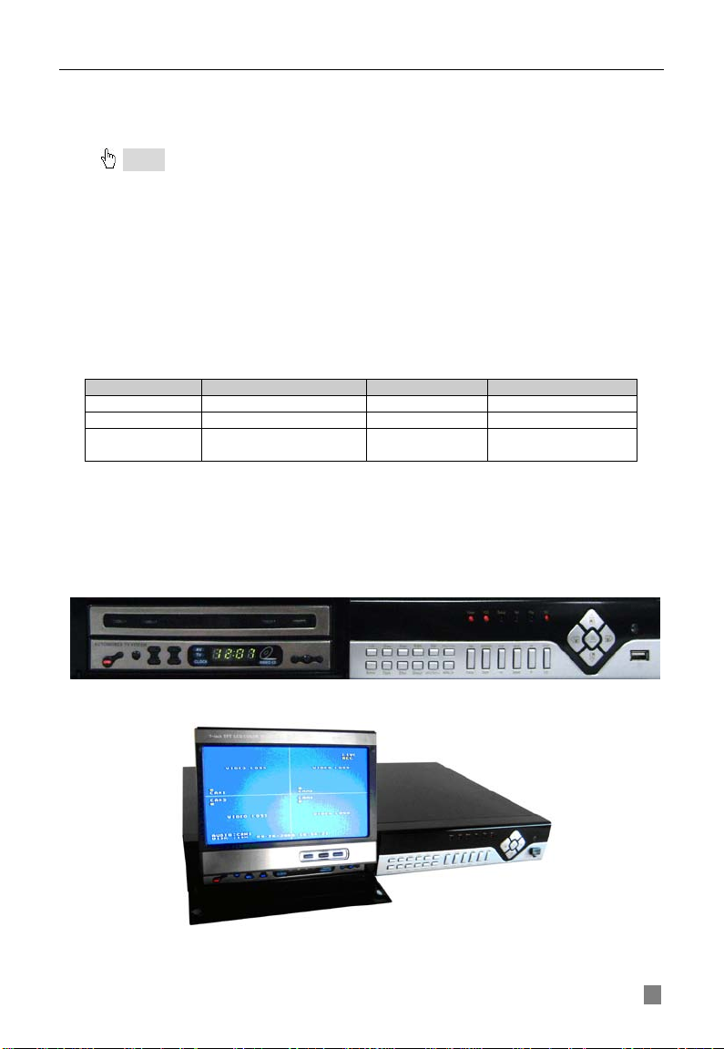
2.2 Front Panel & Interface Terminals
The front panel layouts with the flip screen open and closed are shown
below. The functions of all buttons on the fr ont panel are explained in the
following tables. The product you have may be slightly difference since
we sometimes upgrade or improve our products.
Name Function
6
QSDF8204 Digital Video Recorder User Manual
1
Digital buttons
Input numbers or choose camera s
1. Decrease the value in setup
4
RECORD
Record manually
5
REW
Rewind
To connect USB mouse for control or external
Fig2.1 Front Panel
Item Name Function
2 +/Menu button
3 -/Backup
1. Increase the value in s etup
2. Enter menu in live mode
2. Enter backup mode in live mode
6 PLAY Enter playback interface
7 10+
Choose channel 10 and above
0-9, and double-click is 10.
8 SEARCH Enter search mode
9 FF/PTZ
10 STOP/ESC
11 USB port
1. Fast forward
2. Enter PTZ mode in live
1. Quit playback mode
2. Exit the current interface or status
USB devices like USB flash drive or USB HDD
for backup or firmware update
12 Indicator lights
Working status lights for power, HDD, network,
etc
1. Direction buttons. Move cursor in setup or
Direction/Multi-screen
13
button
control PTZ cameras
2. Change screen display between single &
4 screen
14 Enter button To confirm the choice or setup
15 IR Receiver For remote control
7
QSDF8204 Digital Video Recorder User Manual
Connect to external sensor 1-4.
Connection for PTZ cameras
Connection for network or internet
Audio input, connection for MIC or other audio
Audio output, connection for speaker
S-Video output, connect to monitor
INPUT
For cooling the device
2.3 Rear Panel
Layout subject to change, may be slightly different from your model.
The rear panel sketch and interface buttons are shown below:
Items Names Functions
1 ALARM IN
2 ALARM OUT
3 +5 V and GND
4 COM port
Relay output. Connect to external alarm.
+5 Volt and ground connection
For debugging or data entry
5 RS485
6 RJ45 PORT
7 Not Used
8 AUDIO IN
capture devices
9 AUDIO OUT
10 S-VIDEO
11 VIDEO OUT
12 VIDEO IN
POWER
13
Connect to TV or monitor
4ch Video inputs
DC 12V
To connect USB mouse for control or external USB
14 USB PORT
devices like USB flash drive and USB HDD for
backup or firmware update
15 FAN
8
QSDF8204 Digital Video Recorder User Manual
2.4 Remote Control Introduction
2.4.1 Using Remote Control
Notice
package might not include it.
: Pleas e not e tha t Rem ote Con trol is not a standard part of this DVR. Your
To setup Remote Control:
1. Open the battery cover of Remote Control.
2. Put in two AAA batteries with poles aligned correctly.
3. Replace the battery cover.
If the Remote Control does not work, please check the following:
− Are the batteries positioned correctly?
− Do the batteries still have power?
− Is something blocking the Infrared signal between the
Remote Control and the DVR?
− Are signals transmitted by other devices interfering with
the Remote Control?
Notice
remote control.
: If none of the above problems apply, please contact Q-See to replace the
2.4.2 Remote Control
The layout of the remote control is show n below.
9
QSDF8204 Digital Video Recorder User Manual
Start shutdown to stop firmware running. Do it
before powering off.
Get information about the DVR like firmware
version, HDD information
3
REC Button
To record manually
Number and Letter
Buttons
5
Multi-Screen Button
To choose multi-screen display mode
6
SEARCH Button
To enter file search mode
7
MENU Button
To enter menu
8
ENTER Button
To confirm the choice or setup
9
Direction Button
Move cursor in setup or move PTZ cameras
10
+/- Button
To increase or decrease the value in setup
Button
forward/rewind/stop/single frame play
12
AUDIO Button
To enable audio output in live mode
13
Auto Dwell Button
To enter auto dwell mode
letters, numbers and special symbols
To control PTZ camera
control
The functions of the buttons on the Remote Control are described in the
table below:
Items Names Functions
1 Power Button
2 INFO Button
4
11
Playback Control
14 A Button
15 PTZ Control Button
Input numbers and letters or choose camera
To control playback, Fast
Press the button to change input mode.
Including switches among capi tal lett er, small
Move camera/ZOOM/FOCUS/IRIS/SPEED
10
QSDF8204 Digital Video Recorder User Manual
Symbol
Meaning
Symbol
Meaning
LIVE
Live picture mode
REC
Manual recording
A
Sensor recording
M
Motion r ecording
Percentage of hard
drive us ed
OPEN
CHAPTER 3 Basic Operation Guide
3.1 How to Start DVR
Notice
power voltage.
To start the DVR:
STEP1 Connect the DVR to AC adaptor and plug in. STEP2 Turn on the DVR. STEP3 Wait for the DVR to initialize.
After DVR is powered on, ‘STARTING……’ appears on the screen, which
indicates the DVR is initializing.
After ‘WELCOME’ is displayed, you enter into live display mode. You can
press the "Menu" button to enter Main Menu.
The symbols displayed on the screen are explained in the following table:
: Before powering on the unit, please make sure the pow er input matches the local
DISK
V-LOSS Video loss
3.1.1 Basic operation of TFT LCD Monitor Screen
The basic operation of TFT LCD monitor screen is shown below:
Press OPEN button, the TFT LCD Monitor Screen will pop-up, press OPEN
again it will close.
TFT LCD Monitor Screen Open.
11

QSDF8204 Digital Video Recorder User Manual
MENU
LIVE CONFIG
RECORD CONFIG
ALARM CONFIG
PTZ CONFIG
BASIC CONFIG
USER CONFIG
NETWORK
MANAGER TOOLS
MOTION ALARM
SENSOR ALARM
OTHER ALARM
BASIC CONFIG
IP CONFIG
DDNS CONFIG
DISK MANAGEMENT
SYSTEM LOG
SYSTEM INFO
UPDATE FIRMWARE
LOAD DEFAULT
CLEAR ALARM OUT
SHUTDOWN SYSTEM
Fig 3.2 Main
Fig 3.1 Login
3.2 Main Menu Setting
There is an administrator setup in the DVR. The administrator has control
over all settings. The userna me is "Ad min", an d default password is "123456".
Steps of entering the Main Menu are:
Notice
a mouse the operation may be easier, you would follow the instructions in dialogue boxes and
navigate through menu items. If using the front panel buttons you cannot co ntrol PTZ
cameras, but the other oper ations are the same as the remote control.
STEP1 Press the "Menu" button, input username and password in the
Login interface (as Fig. 3.1), and then you will see the Main Menu (as Fig.
3.2).
: The instructions in the examples are the steps using the Remote Control. If using
STEP2 Move the cursor, and the selected items will be highlighted in yellow STEP3 Press "Enter" key to enter the sub-menu, and press "Menu" key to get back to Main Menu
The structure of the main menu is shown in Fig 3.3.
12
Fig 3.3 Structure of Main Menu

QSDF8204 Digital Video Recorder User Manual
Fig 3.4 Basic Configuration
Fig3.5 Time Adjust
3.2.1 Basic Configuration
Basic Configuration menu is shown as Fig. 3.4.
Fig 3.5 Time adjustment
1. VIDEO FORMAT
There are two video formats: NTSC and PAL. Please select according to your
area, NTSC is used in the USA.
2. TIME POSITION
This item is for setting up the position of the time on the display. There are
three options:
• TOP: Time is displayed on top of the screen.
• BOTTOM: Time is displayed at the bottom of the screen.
• NO: Time is not displayed on the screen
3. Language
There are languages to be selecte d English or Spanish.
4. DVR NAME
Users can set DVR name with letters from ‘a’ to ‘z’ or numbers from ‘0’ to ‘9’.
STEP1 Press "A" button to switch the inputting mode from letters to
numbers
STEP2 Modify the DVR name. STEP3 Press "Enter" key to confirm the operation.
13

QSDF8204 Digital Video Recorder User Manual
5. DVR ID
DVR ID consists of three numbers.
STEP1 Move the cursor to the item. STEP2 Press "Enter" key to modify numbers. STEP3 Enter three numbers, and then press "Enter" key to confirm the
modified entry.
STEP4 Press "OK" button to confirm the operation.
6. DATE FORMAT
There are three date formats:
• Asian Date format: YY/MM/DD
• European Date format: DD/MM/YY
• American Date format: MM/DD/YY
7. TIME ADJUSTMENT
Time Adjustment menu is shown as Fig. 3.5. Please stop recording before
adjusting time.
STEP1 Move the cursor to the item.
STEP2 Modify numbers by using
STEP3 Press "Enter" key to confirm the operation.
Notice
adjusted time and current time will be deleted automatically.
: If you set a time that is before the current displayed time, the record between the
8. BUZZER ALARM
There are seven options to choose: always (continuous buzzer), 5 seconds,
10 seconds, 30 seconds, 1 minute, 2 minutes and 4 minutes.
3.2.2 Live Configuration
Live Configuration menu is shown in Fig. 3.6.
"+" and "-" buttons.
Fig 3.6 Live Configuration
1. CHANNEL
STEP1 Move the cursor to the item.
STEP2 Press "Enter" key to select the channel
2. CHANNEL NAME
User can set the channel name with letters from ‘a’ to ‘z’ or numbers from ‘0’
to ‘9’.
STEP1 Press "A" button to switch the inputting mode between letters and
numbers.
14
QSDF8204 Digital Video Recorder User Manual
STEP2 Enter channel name.
STEP3 Press "Enter" key to confirm the operation.
3. SHOW NAME If selecting "SHOW NAME", the camera name will be displayed in live view. If unselecting "SHOW NAME", the camera name will not be displayed.
4. CHANNEL HIDE
If selecting "HIDE", the video from the channel will not display in live view, but
it will still be recorded. If unselecting "HIDE", the video will be displayed.
5. CHANNEL COLOR
Change the values of contrast, brightness, saturation, and hue of the picture.
6. COPY CONFIG TO
Copy the configuration of one channel to any other selected channels. By
selecting “ALL”, users can copy the configuration to all other channels.
STEP1 Select the channel you want to copy this channel to, or select ALL to copy the configuration to all other channels.
STEP2 Press "COPY" button.
STEP3 Press "Enter" key to confirm the operation.
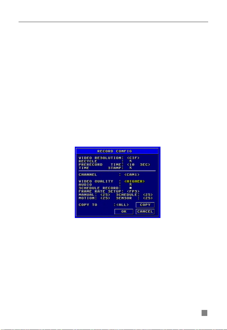
3.2.3 Record Configuration
Record Configuration menu is shown in Fig. 3.7.
Fig 3.7 Record Configuration
1. VIDEO RESOLUTION
This unit supports CIF format.
Resolutions of different video formats are: PAL: 352*288(CIF);
NTSC: 352*240(CIF)
2. RECYCLE Checking the "RECYCLE" option means once the hard drive is filled the DVR will continue to record by covering the previous recording automatically, starting with the oldest. If you do not check "RECYCLE", recording will stop once the hard drive is full.
15
QSDF8204 Digital Video Recorder User Manual
3. PRERECORD TIME
Prerecord time refers to the amount of time recorded from memory before the
alarm was triggered. There are two options: 5 seconds and 10 seconds.
4. TIME STAMP
If selected, record time will be displayed on the bottom of the s creen at
playback
5. CHANNEL
STEP1 Move the cursor to the item.
STEP2 Press "Enter" key to switch the channel and select.
6. VIDEO QUALITY
There are five options: lowest, lower, medium, higher and highest. The higher
the picture quality, the clearer the image is, but more hard drive space wil l b e
taken up.
7. AUDIO If you check "AUDIO", DVR will record audio with video recording. Otherwise, it will not record audio.
Notice: • The default setting is that Audio input 1 matches channel1 and Audio input2
matches channel2.
•
to the corresponding channel.
When playing back the record, please press "AUDIO" button to switch the sound
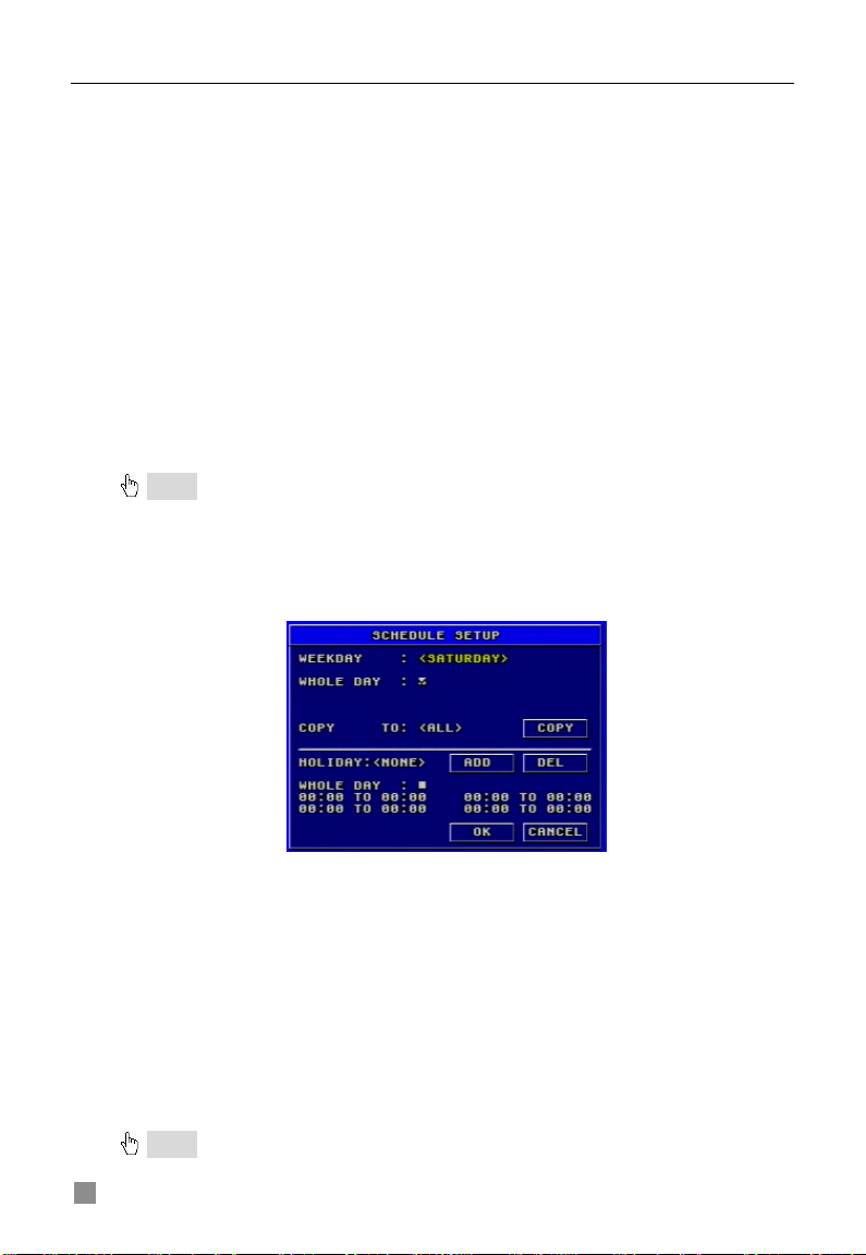
8. SCHEDULE RECORD
Schedule Record Setup is shown as Fig. 3.8.
Fig 3.8 Schedule Setup
STEP1 Move the cursor to "SCHEDULE RECORD" option STEP2 Check "SCHEDULE RECORD", and the “Setup” window will pop
up.
STEP3 Press "Setup" to enter the Schedule Setup menu.
Press "ESC" button on the front panel to get back to upper menu. STEP4 In the Schedule Setup menu, move the cursor to select a day, and check “whole day” if you want to record all of the time. STEP5 If you only want to record certain time periods press "Enter" key to set up time. STEP6 Press "+" and "-" buttons on the front panel to modify the time.
Notice: When you use t he mouse, you need roll the middle wheel to modify the time.
16
QSDF8204 Digital Video Recorder User Manual
Fig 3.10 Motion Alarm Configuration
STEP7 Press "Enter" key to confirm the setup.
On weekday and holiday, you can select whole day or set four periods in a
day to record.
9. FRAME RATE SETUP
Frame rate is the number of pictures recorded each second. If choosing 15,
the picture-recording rate is 15 frames per second.
User can set frame rates based on the record mode.
If the video format is NTSC, there will be five frame rates to choose: 1, 3, 7,
15 and 30. The maximum frame rate is 30.
If the video format is PAL, there will be five frame rates to choose: 1, 3, 6, 12
and 25. The maxi m um frame rate is 25.
10. COPY TO
This option allows you to copy the settings of thi s channel to other selected
channels.
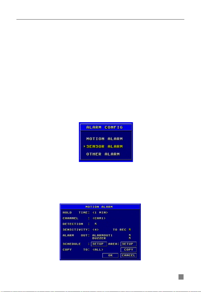
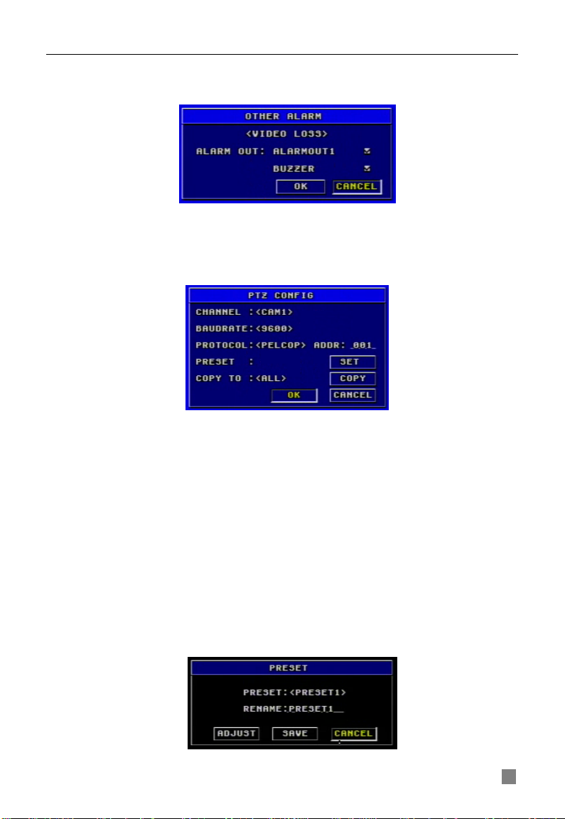
3.2.4 Alarm Configuration
Alarm Setup menu is shown as Fig. 3.9.
MOTION ALARM
If you select Motion Alarm in Alarm Configuration, the submenu shown as Fig.
3.10 will be displayed.
Fig 3.9 Alarm Configuration
17

QSDF8204 Digital Video Recorder User Manual
1. HOLD TIME
This sets the continued recording time after an alarm is triggered. There are
two options: 1 minute and 2 minutes. It also determines the interval between
motion detection events. If the HOLD TIME is 1 minute, if new motion is
detected within this period it will be considered part of the previous event
instead of the start of a new event.
2. CHANNEL
STEP1 Move the cursor to the channel. STEP2 Press "Enter" key to switch the channel and select.
3. DETECTION
Checking "DETECTION" means to enable motion detection, not checking
means motion detection will not be enabled.
4. SENSITIVITY
This is the sensitivity level of the motion sensors.
The range is from ‘1’ to ‘8’. The higher the value, the more sensitive.
5. TO REC
If selecting "TO REC", DVR will record when motion is detected. If not, DVR
will not record when motion is dete cted.
6. ALARM OUT
There are two options: ALARMOUT1 and BUZZER.
• When ALARMOUT1 is selected and an alarm is triggered, the DVR will
give send signal to the alarm out port.
• When BUZZER is selected and the sensor is triggered, DVR will give a
buzzer alarm.
When the alarm output is unselected, DVR will not send an alarm.
7. SCHEDULE
This is the schedule for the motion detection. The default schedule is
everyday. Press "SETUP” button to set the motion detection schedule.
8. AREA
STEP1 Move the cursor to “setup”.
STEP2 Press "SETUP" button to enter the Area Setup submenu.
It displays the selected detection area (refer to Fig. 3.11). There
are four options:
− ALL: motion anywhere in the area will be detected as shown
in the picture.
− CUSTOM: You can select part of the area to be detected.
− NULL: No area will not be open to motion detection
− BACK: Go back to Motion Alarm Configuration menu.
18

QSDF8204 Digital Video Recorder User Manual
Fig 3.11 Detection Area Setup
Sub-steps for manually selecting the detection area are described below:
1. In the Area Setup submenu, choose "CUSTOM" option.
2. Press "Enter" key to confirm the operation.
3. Pre ss "Up", "Down", "L e ft" and "R ight" buttons to c hoos e the
area which needs to be detected
4. Press "Enter" key to select or cancel the area.
5. Pres s "Esc" button to confirm the option and exit "CUSTOM"
option.
STEP3 Press "BACK" option to go back the Motion Alarm Configuration
menu.
Notice
the same time. The alarm events can be found in Search by Event”, please refer to the ‘3.3.2
Search’ function in ‘3 Search by Event’.
: If continuous recording mode, manual record and alarm record are activated at
9. COPY TO
Use this option to copy the settings of this channel to any other selected
channel.
SENSOR ALARM
Sensor alarm submenu is shown as Fig. 3.12 . Every Sensor m atches one or
more channels.
Fig 3.12 Sensor Alarm Configurat ion
19

QSDF8204 Digital Video Recorder User Manual
1. HOLD TIME
This sets the continued recording time after an alarm is triggered. There are
two options: 1 minute and 2 minutes. It also determines the interval between
motion detection events. If the HOLD TIME is 1 minute, if new motion is
detected within this period it will be considered part of the previous event
instead of the start of a new event.
2. SENSOR
STEP1 Move the cursor to the "SENSOR" option. STEP2 Press "Enter" key to switch the Sensor.
3. DETECTION This is the switch of the sensor alarm. If you check "DETECTION", DVR will begin detecting. If you do not check it, the detection function is disabled.
4. TYPE
Press "Enter" key to enter the sub-menu. There are two options: NO and NC.
‘NO’ means normal open. If ‘NO’ is chosen, the DVR will be triggered when
the alarm when the voltage drops.
‘NC’ means normal close. If ‘NC’ is chosen, the DVR will be triggered when
the alarm sends a high voltage charge.
5. TRIGGER RECORD
One channel can connect with one sensor. However, one sensor can trigger
one or more channels.
STEP1 Move the cursor to "TRIGGER RECORD" option. STEP2 Select the channel you want that sensor to trigger. STEP3 Press "Enter" key to confirm the operation.
For example, if you select the sensor named SENSOR1 and the trigger
records named CAM1 and CAM2, it will record on channel 1 and channel 2
when the SENSOR1 is triggered.
6. ALARM OUT
There are two options: ALARMOUT1 and BUZZER.
• When ALARMOUT1 is selected and the sensor is triggered, DVR will
give send a signal to the alarm out port.
• When BUZZER is selected and the sensor is triggered, DVR will give
buzzer alarm.
• When the alarm output is unselected, DVR will not send alarm.
7. SCHEDULE
This is the schedule of when the sensor detection is active. The default
schedule is everyday.
8. COPY TO
Users can copy the setting of this channe l to all or any other sele cte d
channel.
20
QSDF8204 Digital Video Recorder User Manual
Fig 3.14 PTZ Configuration
OTHER ALARM
Other Alarm submenu is shown in Fig. 3.13 . O ther alarm includes video loss,
disk full and so on.
Fig 3.13 Other Alarm Configuration
There are two options of alarm output: ALARMOUT1 and BUZZER. Their
functions are same with that in sensor alarm.
3.2.5 PTZ Configuration
PTZ Configuration menu is shown in Fig. 3.14.
1. CHANNEL
Set the channel connecting to the Speed Dome.
2. BAUDRATE
There are five options for baud rate: 1200, 2400, 4800, 9600, and 19200.
3. PROTOCOL
Choose PTZ protocol. Currently the DVR supports PELCO_D, PELCO_P,
MINKING, NEON, STAR, VIDO, DSCP, VISCA and LILIN.
4. ADDR
Set PTZ address. Press "Enter" key and use the number key, "+" and "-"
buttons to set.
5. PRESET
STEP1 Press "SET" button to enter Preset submenu shown in Fig. 3.15.
There are 16 preset points that can be set in every channel.
Fig 3.15 Preset
21

QSDF8204 Digital Video Recorder User Manual
Fig 3.16 User Configuration
STEP2 In Preset submenu, press "Enter" button to switch the preset point
needing to be reset.
STEP3 Press "ADJUST" button to enter PTZ mode.
STEP4 On the front panel, press "ZOOM", "FOCUS", "SPEED", "IRIS", "+"
(MENU) and "-" (PTZ) buttons to modify the position of the preset point.
STEP5 Press "UP", "DOWN" , "RIGHT" and "LEFT" buttons to rot ate the
Speed Dome.
STEP6 Press "ESC" button to come back to Preset menu.
STEP7 Press "SAVE" button to save the setting, and press "CANCEL" to
discard the setting.
Notice: how to use the presetting point:
press "PTZ" button to enter PTZ mode, then press the number key such as "1", and the
Speed Dom e w ill move to preset point 1.
Users can use the number keys to switch the preset point in PTZ mode. First
6. COPY TO
You can use this option to copy the settings of this channel to all channels or
any other selected channel.
3.2.6 User Configuration
User Configuration is shown as Fig 3.16. The default username is Admin.
Administrator can add users, set users’ authorization and delete users.
22

QSDF8204 Digital Video Recorder User Manual
Fig 3.17 Authority Setup
1. AUTHORIZATION CHECK If you put a chec kmark in "AUTHORIZATION CHECK", all users need to input the password before entering the Main Menu.
If you do not check "AUTHORIZATION CHECK", users can enter the system
directly without password.
2. USER
Press "Enter" key to switch to another user. Use "+” and "-" buttons change
users.
3. PASSWORD
The default password of administrator is ‘123456’. Users can change
password that is made up of numbers from 0 to 9.
4. AUTHORIZATION STEP1 Move the cursor to "User" option, then press "Enter" key to switch to the user whose authorization you want to modify.
STEP2 Move the cursor to "SETUP" button on the screen.
STEP3 Press "Enter" key, Authority Setup menu (refer to Fig. 3.17) will
pop up.
STEP4 In the Authority Setup menu, move the cursor to "DEFAULT".
STEP5 Press "Enter" key. The default authorization will be set.
The default authorizations include:
− Live preview, playback, backup, and Record in l ocal system
− Live preview, playback, backup, and Record in remote
network client
5. NEW USER
STEP1 Move the cursor to "ADD" button on the screen. STEP2 Press "Enter" key, the Add User menu will display. STEP3 Input username and password. STEP4 Press "OK" button to confirm the option.
Username is formed by numbers or letters with a maximum of 15 char act ers.
The Password is numbers between 0 and 9.
23

QSDF8204 Digital Video Recorder User Manual
Fig 3.18 Network Configuration
6. DELETE USER
STEP1 Move the cursor to the "DEL" button on the screen.
STEP2 Press "Enter" key to confirm the operation. When a u ser is de leted,
the username and pas sword will no longer exist in the system.
3.2.7 Network Configuration
Network Configuration menu is shown as Fig. 3.18.
Fig 3.19 Basic Configuration
BASIC CONFIGURATION
Basic Configuration submenu is shown as Fig. 3.19.
STEP1 Move the cursor to “Basic configuration”.
STEP2 Press "Enter" key to enter the Basic Configuration menu.
1. NET SERVER
If you select the check box and set the port number of the server, you will
enable the NET SERVER.
2. NET VIDEO QUALITY
This refers to the picture quality in remote surveillance. There are three
options: low, medium and high. The higher of th e qu ality v alu e, t he clearer the
image is, the lower the quality value, the less bandwidth the video takes up.
The default level is medium.
IP CONFIGURATION
IP Configuration submenu is shown as Fig. 3.20.
24
Fig 3.20 IP Configuration
QSDF8204 Digital Video Recorder User Manual
Fig 3.21 System Information
This is the DVR’s IP configuration. There are three options: STATIC, DHCP
and PPPoE.
If you use the Static IP address option you will need to access the router the
DVR is attached and get the setup informat ion. You can do this by going to
the run option on a computer that is attached to the same router as the DVR
and typing cmd or command to get to a command prompt. At the command
prompt type ipconfig and hit ENTER to access the network information. The
screen will list the computer’s I P address, t he Sub net M ask, and the G atew ay.
The IP address you assign to the DVR must have the same first 3 sets of
numbers as the Gateway. If the computer’s IP address end s in a 1 or 2-digit
number, y ou can sele ct an IP address ending in 100, if the computer’s IP
address ends in a number in the 100s then select an IP address ending in
200.
STEP1 Input IP Address, Subnet Mask and Gateway STEP2 Press "OK" button to modify the IP Configuration menu.
If you select DHCP, the router will automatically assign the IP address.
After
selecting DHCP, you need to wait about 30 seconds. The automatically
assigned IP will be displayed in the system information window.
If you are attachin g the DVR directly to a DSL or cable modem/router, you can
use the PPPoE option. You need to input usern ame and p a s sword when
connecting to internet. You would get the username and password
information from your internet service provider.
If you press the "INFO" button, S y stem I nf orm atio n menu can be displayed on
the screen as long as the DVR connects with the network well (refer to Fig.
3.21).
Notice: • If the local area netw ork has a DHCP server or the router the DVR is attached to
supports DHCP we recommend using the DHCP option.
•
you need wait for a while for the settings to take effect.
Before you set PPPoE, you need to reboot the modem. After s et ting the PPPoE,
25
QSDF8204 Digital Video Recorder User Manual
Fig3.28 Disk Management
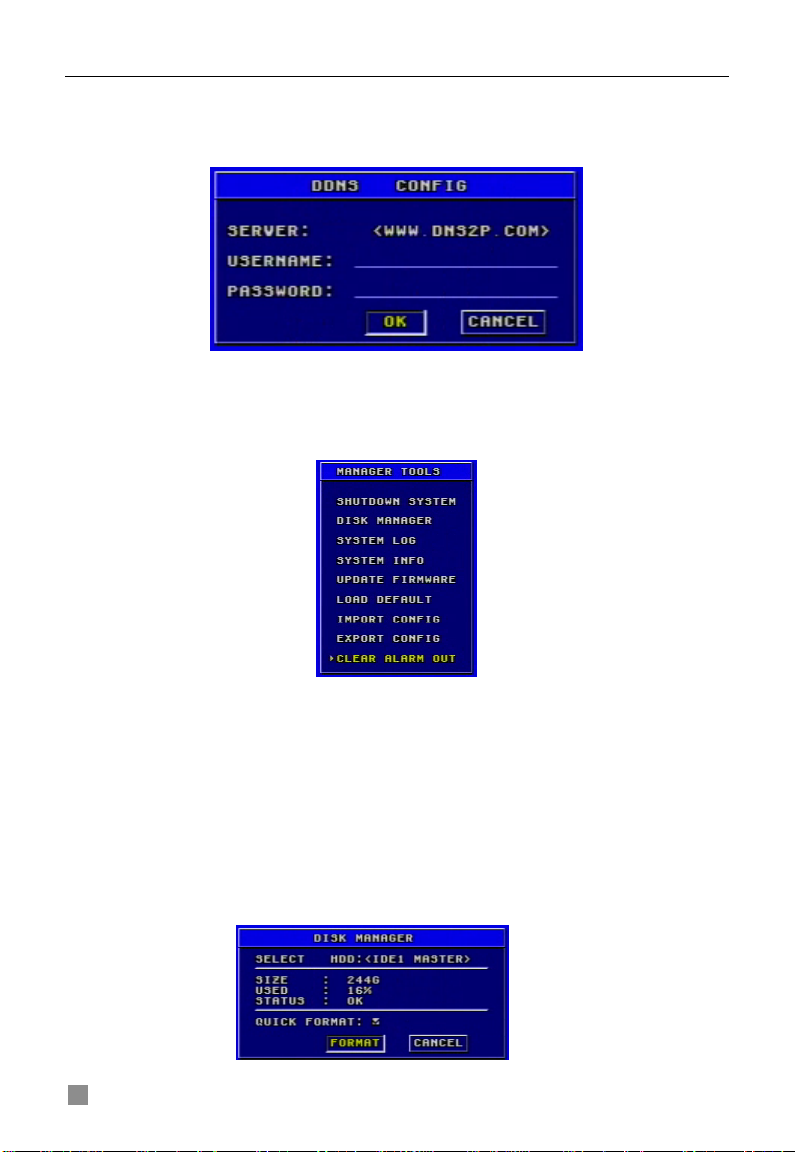
DDNS CONFIGURATION
DDNS Configuration submenu is shown as Fig. 3.22. The DVR does not
currently support any DDNS servers in the USA, support may be added in
future firmware updates.
Fig 3.22 DDNS Configuration
3.2.8 Manager Tools
The Manager Tools menu is shown as Fig. 3.27.
Fig 3.27 Manager Tools
SHUTDOWN SYSTEM
This option is used to shut down the system. STEP1 Enter the SHUTDOWN submenu.
The following words will be shown: ‘Are you sure to shut down
DVR system?’.
STEP2 Press "Enter" key to confirm the operation.
DISK MANAGER
Disk Manager Submenu is shown as Fig. 3.28.
Fig 3.28 Disk Manager
26
QSDF8204 Digital Video Recorder User Manual
Fig 3.29 Log Search
There are two options: FORMAT and CANCEL.
1. QUICK FORMAT
If you check this item, you can format the hard drive quickly.
2. FORMAT
STEP1 Select "FORMAT" button.
STEP2 Press "Enter" key, a warning will pop up: ‘Format will erase all data
on this hdd! Format now? ’
STEP3 Press "OK" button to format the HDD; Press "CANCEL" or "ESC"
button to cancel this operation.
Notice: • When a hard drive is used for the first time the system will remind you to format
the HDD when the DVR is started up. HDD cannot record until it is formatted.
•
Before you can format the HHD you must stop recording and playing back.
•
capacity is, the longer it takes. Normally, a 40G HDD tak es about eight seconds to format.
Time it takes to format t he HDD depends on the HDD capacity. The higher the
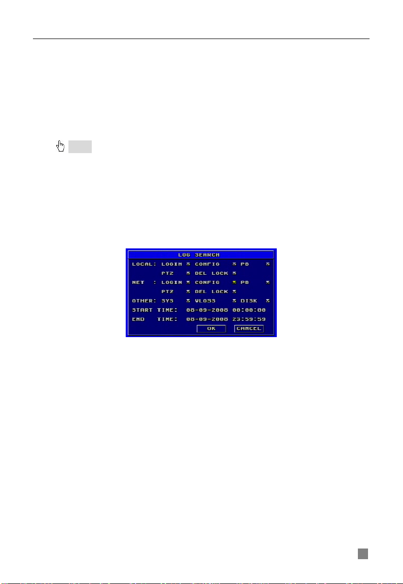
SYSTEM LOG
System log submenu is shown as Fig. 3.29.
The DVR will note all operations, status, and time automatically while working.
You can view them through searching using the Log Search.
1. LOCAL, NET, AND OTHER
Check the corresponding ite m s of loc al operation, network client operation and other operation first. (Note: VLOSS is video loss)
2. TIME
Select start time and end time of the log file you want to view.
Press "OK" button to view the event log; Press "CANCEL" or "ESC" button to
cancel this operation.
The information in log files contains start time, end time and log file types. For
example, 110707:092151 means 2007-7-11 9:21:51 and N-L means the
LOGIN of the NET.
If there are too many log lists, you can use "PREV" button to page up and
"NEXT" button to page down.
27

QSDF8204 Digital Video Recorder User Manual
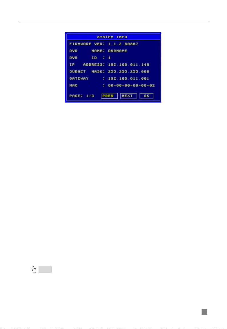
SYSTEM INFORMATION
System information subm enu is shown as Fig. 3.30. It displays the
information about the system, such as firmware version, device name, DVR
IP ADDRESS, Client information and so on.
Fig 3.30 System Information
Press the "INFO" button on the front panel and it will display the system
information on the screen.
UPDATE FIRMWARE
Fig 3.31 Update Firmware
Update Firmware submenu is shown as Fig. 3.31. Users can use USB flash
drive to update the firmware.
Steps are described below:
STEP1 Make sure the firmware update is on the USB flash drive. STEP2 Enter the menu after word-‘USB’ is displayed on the live mode. STEP3 Move the cursor to "UPDATE" button. STEP4 Press "Enter" key to start updating. STEP5 After the program is upgraded, the system will restart.
LOAD DEFAULT
Fig 3.33 Load Default
Load Default menu is shown as Fig. 3.33. Click YES, and it will recover the
default setting installed at the factory.
28
QSDF8204 Digital Video Recorder User Manual
IMPORT CONFIGURATION & EXPORT CONFIGURATION
This function is used to help users manage multiple DVRs conveniently. When users need to set up the same parameters in more than one DVR, they can copy one DVR’s setting to all others without setting them up one by one. EXPORT CONFIGURATION can copy one DVR’s parameter settings to a USB flash drive; and then use IMPORT CONFIGURATION to input the settings copied onto the USB flash drive from the first DVR to another DVR.
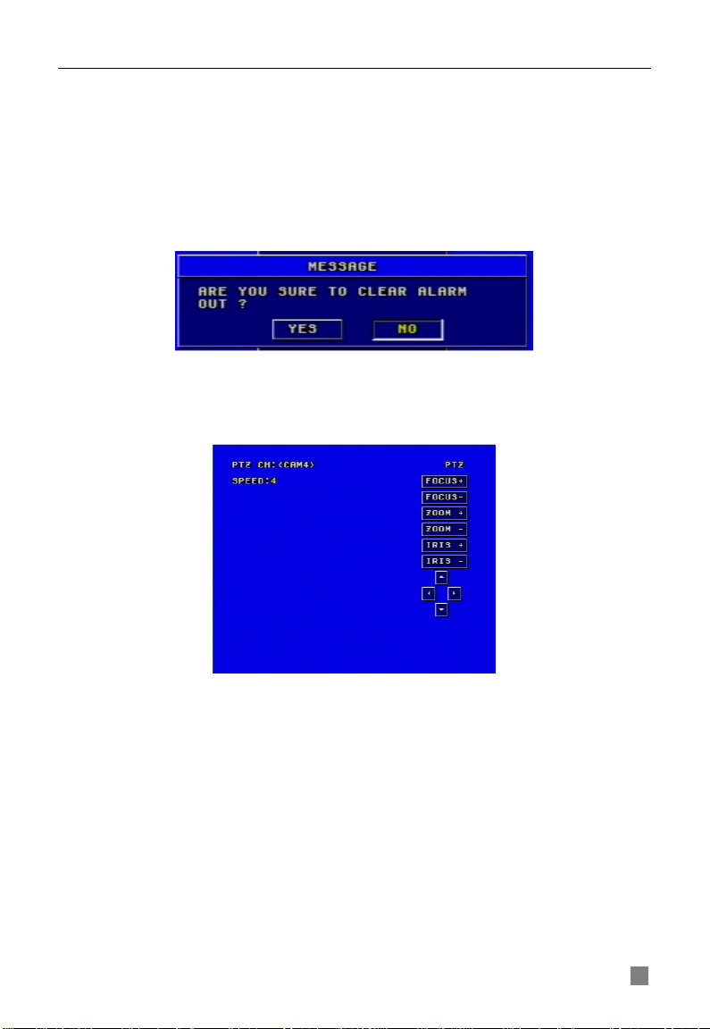
CLEAR ALARM OUT
This item is to clear the current alarm out, please refer to Fig. 3.34.
Fig 3.34 Clear Alar m Out
3.3 Shortcut Menu
3.3.1 PTZ
Fig 3.35 PTZ Mode
PTZ mode is shown as Fig. 3. 35. To switch the channel to which the video
output of the Speed Dome connects you press "PTZ" button to enter the PTZ
mode.
In the live view of PTZ mode the default channel is channel 1, you can use
mouse to change the channel number to enter the corresponding channel
PTZ mode.
SPEED
STEP1 In PTZ mode, press "Speed" button.
STEP2 Press "+" and "-" buttons to change the rotational speed.
STEP3 Press "Up", "Down", "Left" and "Right" buttons to rotate the Speed
Dome to a certain position.
29
QSDF8204 Digital Video Recorder User Manual
ZOOM
STEP4 In PTZ mode, press "ZOOM" button.
STEP5 Press "+" and "-" buttons to zoom in and zoom out.
FOCUS
STEP1 In PTZ mode, press "FOCUS" button.
STEP2 Press "+" and "-" buttons to control focus.
IRIS
STEP1 In PTZ mode, press "IRIS" button.
STEP2 Press "+" and "-" buttons to change the brightness of the Speed
Dome.
3.3.2 Search
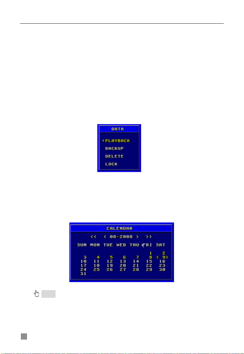
Press the "Search" button, there are five submenus dis played on the screen: PLAYBACK, BACKUP, DELETE and LOCK. Data menu is shown as Fig.
3.36.
Fig 3.36 Data Menu
PLAYBACK
1. Select the Date
STEP1 In Playback menu, move the cursor to Calendar
STEP2 Press "Enter" key to enter the Calendar submenu.
Calendar submenu is shown as Fig. 3.37.
Notice : You can search for records by time search or event search. The times displayed
in red have record files.
Fig 3.37 Calendar
30
QSDF8204 Digital Video Recorder User Manual
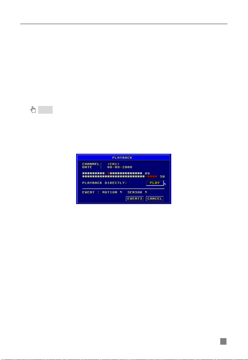
2. Search by Time
All records can be searched through this option. Steps of searching by t ime
are below:
STEP1 In Calendar submenu, select date.
STEP2 Press "Enter" key to enter the Playback submenu, refer to Fig.
3.38.
STEP3 Press "Enter" key to select channels.
STEP4 Select time of the day
The times in red have record files. The first line is hour, and the
second line is minute.
STEP5 Select "PLAY" button.
STEP6 Press "Enter" key to play the record.
Notice: • the DVR supports playing back in full screen mode and quad screen mode.
buttons or "Up", "Down", "Left" and "Right" buttons to swit ch the channel.
record playing bac k as normal spe ed.
to play or stop channel audio.
- When you play back the rec ord in full screen mode, you may use the number
- When you play back the record in quad screen mode, you can only see the
•
When you play back the record, you may press "INFO" button on the fr ont p anel
Fig 3.38 Playback
3. Search by Event
Steps for searching by event are below:
STEP1 In Playback submenu, select the camera and date. The dates having recorded events are highlighted in red. STEP2 Move the cursor to event option.
The Event search types are: MOTION and SENSOR
STEP3 Press the "Down" button to move the cursor to "EVENTS" button in
the submenu.
STEP4 Press "Enter" key to enter the event list.
STEP5 Vies the list information.
Taking one of the event records information as an example the
meanings of the words are described below:
− CH: Channel
− START TIME: The start time of the record.
− TYPE: The type of the event. There are two types of event:
MOTION and SENSOR.
− M: Motion detection
− A: Sensor detection
− LOCK: Lock status of files.
31
QSDF8204 Digital Video Recorder User Manual
STEP6 Choose an event record. STEP7 Press "Enter" key to play back the record STEP8 Press "Stop" button to get back to live display mode.
Notice
: If event list is over one page, use "PREV" and "NEXT" buttons to view next page.
BACKUP & VIEW BACKUP
1. BACKUP
Select the Backup submenu in the Data menu to enter the Backup submenu
shown as Fig. 3.39.
Fig 3.39 Backup
(1) BACKUP MEDIA
Backup media refers to the device you are copying the record to. There are
five options: DVD-R, DVD-RW, DVD+R, DVD+RW and USB disk. They
connect with DVR through USB interface.
(2) BACKUP FILE
It denotes the format of backup files. This system supports AVI and DAT video
formats.
• When selecting the format that DVR supports, the video format of
backup files is DAT.
• Before playing the record of AVI format, it is necessary to in s t all the
decoder at first.
(3) ST AR T TIME
It is start time of recording at backup. The first line is hour, and the second line
is minute. Users should ch oos e the date firstly and choose the time secondly.
(4) END TIME
It is end time of recording at back up. The first line is hour, and the second line
is minute. Users should choose the date firstly and choose the time secondly.
(5) CHANNEL
It supports to select more than one channel at the same time.
(6) EVENTS
There are two options: motion and sensor. If you want to backup all records,
please select "ALL".
32

QSDF8204 Digital Video Recorder User Manual
(7) BACKUP
Before to backup, users should select BACKUP MEDIA, BACKUP FILE,
CHANNEL, START T IME, END TIME a nd EVENTS.
STEP1 Press "BACKUP" button, the backup information of DVR will display on the screen (refer to Fig. 3.40).
Fig 3.40 Backup Information
STEP2 Press "START" button, and backup will start.
The progress of backup will b e disp lay ed o n the screen. If stopping
recording at backup, its speed will be faster. STEP3 When the backup is over, the system will pop up a dialog box saying ‘BACKUP COMPLETELY’.
2. VIEW BACKUP
If backing up with AVI format, most media players can play directly as long as
to install a decoder in advance. Installa tion method: Ent er "D ecode" file (being
created automatically by system at your backup.), then double-click
"InstallDecode.bat" fil e to Install successfully.
If backing up with the format DVR supports, the file player will be copied
automatically in the file copying media.
DELETE
Delete submenu is shown as Fig. 3.42. The operation is shown below:
Fig 3.42 Delete
STEP1 Press "Enter" key to enter the Delete submenu.
STEP2 Press "Enter" key to select the record.
STEP3 Move the cursor to "DELETE" button and press "Enter" key,
information will be given as below:
‘SOME RECORDS WILL BE DELETED, CONTINUE?’
STEP4 Select "OK" button.
STEP5 Press "Enter" key to delete this record.
33
QSDF8204 Digital Video Recorder User Manual
LOCK/UNLOCK
Lock submenu is shown as Fig. 3.43. Its function is to lock or unlock the
record.
Fig 3.43 LOCK/UNLOCK
Use "Enter" key to change the state. If a record event is locked, it cannot be
deleted or covered.
3.3.3 Information
Press "INFO" button, and the information will appear on the screen, such as
HDD quantity, usable rate of HDD, record mode including
manual/alarm/motion, etc.
3.3.4 Other
• In live display mode, if pressing "Up" button, it will display the first
channel in full screen.
• If pressing "Down" button, it will display the second channel in full
screen.
• If pressing "Left" button, it will display the third channel in full screen.
• If pressing "Right" button, it will display the fourth channel in full screen.
• If pressing "Enter" button, it will display the four-divided channel.
• If pressing "Audio" button, it will switch the voice of corresponding
channel in live display mode.
34
QSDF8204 Digital Video Recorder User Manual
CHAPTER 4 Remote Surveillance
4.1 Accessing DVR
The system supports remote surveillance through a network or Internet.
This DVR supports five users logging in at the same time.
First, the DVR needs to be con nected with a router so that it can be accessed
over the network or Internet. As for network access, it suppor t s
Win2000/XP/Vista. Second, you need to set up the network configuration in
the DVR to work with the router. The specific setup steps are shown in the
following sections.
4.1.1 Accessing DVR Over a Network
STEP1 Input IP address, Subnet, and Gateway, please refer to section
3.2.7 Network Configuration. If using DHCP, please enable DHCP in both of
DVR and router. STEP2 Enter “Video” submenu to set network video parameters like resolution, frame rate, etc. STEP3 Open an Internet Explorer browser on a computer on the same network. Input the IP addr es s of the DVR in an Internet Explorer textbox and hit enter. STEP4 Internet Explorer will download ActiveX automatically. (Notice: Internet Explorer must be set up to permit downloading ActiveX controls. Please refer to Q7 in FAQ chapter) Then a window pops up and asks for user name and password. STEP5 Input name and password correctly, and enter. It will show the picture below:
Fig 4.1 Network Client Interfac e
35

QSDF8204 Digital Video Recorder User Manual
4.1.2 Accessing DVR Over the Internet
When accessing the DVR over the Internet, in addition to the above steps, you
would then need to forward port 80 on the router the DVR is attached to, to the IP
address of the DVR. You can get instructions on how to do this for most popular
routers by going to the www.portforward.com website. On this website click on the
orange “Routers” link in the second paragraph (RED box in Fi g 4.1.1), which will
open a list of router manufactures, then find the brand and model of your router on
the list and click on the link. On the next page that opens click on the orange
“Default Guide” link ( BLU E b ox in F ig 4.1. 2), t his w ill t ake you to the port forwarding
instructions for your router.
Fig 4.1.1
Fig 4.1.2
When you ac cess th e DVR from a remote computer, you also need to use a
different address in the Internet Explorer browser window. Instead of entering
the IP address of the DVR you need to enter the public IP address of the
router the DVR is attached to. You can get this address by going to
www.myipaddress.com from a computer that is attached to the same router
as the DVR. This website wil l display the box in Fig 4.1.3 below that shows
the IP address you need to use. It will be in the space where the below
example shows 76.254.183.54.
36
 Loading...