

Page 1
Page 2
replac ed.
Safety Precautions
The lightning flash with arrowhead symbol, within an equilateral
triangle, is intended to alert the user to the presence of insulated
dangerous Voltage within the product’s enclosure that may be
sufficient magnitude to constitute risk of electrical shock to persons.
The exclam ation point within an equilateral triangle is intended to
alert the user to the presence of important operation and
maintenance (servici ng) instructi ons in the li terature accom panying
the appliance.
Warranty
and Service
Attention: installation should be performed by qualified service
Personnel o nly in accordance with the National Elect rical Code or
applicable local codes.
Power Disconnect. Units with or without ON-OFF switches have
power supp lied to the unit w henever the pow er cord is i nserted i nto
the power source; however, the unit is operational only when the
ON-OFF switch is the ON position. The power cord is the main
power disconnect for all unites.
CAUTION: Danger of explosion if battery is incorrectly
Replace only with the same or equivalent type recommended by the
manufacturer. Dispose of used batteries according to the
manufacturer’s instruction.
During the warranty period (one year for Hard Disk), we will repair or
replace the hard disk free of charge.
Be sure to have th e m odel num ber, s erial num ber and v endor st ick
on hard disk for service representative.
About this document
Before install ing stand alone DVR, be sure to thorou ghly review and foll ow the instructions in
this Users Manual. Pay particular attention to the parts that are marked NOTICE.
Also, when connecting with external application, first turn the power OFF and follow manual
instruction for appropriate installation.
2
Page 3

Before reading this document
1. This document is intended for both the administrator and users of this stand alone DVR
Model.
2.This manual contains information for configuring, managing and using this stand alone DVR
Model.
3. To prevent fire or electrical shock, do not expose the product to heat or moisture.
4. Be sure to read this manual before using this stand alone DVR Model.
5. For questions and technical assistance of this product, contact Q-see.
►Strong recom mendation on installation of the DVR unit
1. Verify that the electricity at the place you want to install the DVR unit is stable and meets
our electrical requirements.
Unstable electricity can cause malfunction of the unit or cause critical damage to the unit.
Notice: We also STRONGY recommend that you plug the DVR and cameras into a
Transient Voltage Surge Protector (UL-1449 rating). Look for a clamping voltage of
330 or lower, Joule rating of at least 400, and a response time of 10 nanoseconds or
less.
2. Several chips on the main board of the DVR unit and hard drive inside the unit generate
heat and it must be properly discharged.
Do not put any objec ts near the exhaust port (fan) on the left side of the unit and do not
block the opening (fresh air in-take) on the right side of the unit..
3. Put the DVR unit in a well-ventilated place and do not put heat-generating objects on the
unit. When it is installed inside 19 inch mounting racks together with other devices check
that the built-in ventilation fan of the rack is properly running.
3
Page 4

CONTENTS
1. FEATURES AND FUNCTION…………………………………………………………………….…..5
2. UNIT DESCRIPTION OF FRONT PANEL.…………………………………………………..……….6
3. REAR PANEL AND SYSTEM CONNECTION…..……………………………………………………8
4. REMOTE CONTROL…………………………………………………………………………………12
5. SYSTEM SETUP………………….………………………………………………..………………..12
5.1. SETUP MENU.………………..…………………………………………………………………12
5.2. SYSTEM SETUP…………………………………………………………………………………14
5.2.1. TIME/DATE SET……………………………………………………………………………...14
5.2.2. HDD FORMAT SET…………………………………………………………………………15
5.2.3. FACTORY RESET………………………………………………………………………….15
5.2.4 CHANGE PASSWORD………………………………………………………………………16
5.2.5 FIRMWARE UPDATE…………………………………………………………………………17
5.3. DISPLAY SETUP………………………………………………………………………..………18
5.3.1. CAMERA NAME SET…………………………………………………………………..……18
5.3.2. COLOR SET.……………………………………………………………………………..…19
5.3.3. AUTO SEQUENCE SET…………...………………………………………………………20
5.4. RECORD SETUP………………………………………………………………………………….20
5.4.1. AUDIO CH SET………………………………………………………………………………21
5.4.2. REC CH SET.……………………………………………………………………………..…22
5.4.3. RECORD LENGTH SET………………………………………………………………..…22
5.5. NETWORK SETUP.……………………………………………………………………………….22
5.5.1. N/W ENABLE SET……………………………………………………………………………23
5.5.2. MAC SET………………………………………………………………………… …………24
5.6. SENSOR SETUP…………………………………………………………………………………24
5.6.1. MOTION DETECTION SETTINGS…………………………………………………………25
5.6.2. MOTION AREA SET…………………………………………………………………………26
5.7. SCHEDULE SET…………………………………………………………………………………27
5.8. USB BACKUP…………………………………… ………………………………………………27
5.9. STORAGE INFO…………………………………………………………………………………28
5.10. PTZ SET…………………………………………………………………………………………28
6. QUICK USER GUIDELINE……………………………………………………………………………29
7. USING THE NETWORK VIEWER……………………………………………………………………38
8. MAIN STANDARD & PARAMETER CHART……………........…………………………………44
9. TROUBLE SHOOTING GUIDE……………........……………........………………………………45
10. RECORD TIME TABLE……………...……......……………........…………………………………47
11. INTERNET VIEW/PLAYBACK CONFIGURATIONS………........………………………………48
Q-SEE PRODUCT WARRANTY…………………………………………………………………...51
4
Page 5

1. FEATURE AND FUNCTION
l Video input: 16channels; Video output: 3channels.
l Audio input: 4channels; Audio output: 2channels.
l 16 alarm input and 1 rela y alarm output.
l Compression mode: M-JEPG.
l Support network view.
l Support USB backup.
l Compatible with NTSC and PAL form at.
l Support zoom, auto function, watermark security.
l Four optional level s of image quality: very high, high, low, very low. Record and play-back
frame rate are changeable.
l Support alarm recording, time recording.
l Suppor t v ideo loss and m otion detecti on functions.
l Multi-function searches: be ab le to distingui sh diff erent alar m records and time records f rom
ordinary records; be able to search by time, by segment or by event.
l Support var ious p layback m odes: pause, sev eral fast forw ard and backward play modes.
l Eq uipped wi th r emote dev ice and PTZ control enables (RS485).
l Triplex operation can play back and se arch w hile it is recording.
l 480frame (NTSC, PAL is 400) per second for view, 120frame (NTSC, PAL is 100) per
second for recording.
l SATA Hard Disk Interface, support Over 500G Byte.
5
Page 6
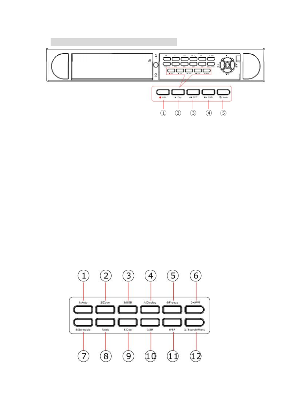
2. UNIT DESCRIPTION OF FRONT PANEL
2.1 Recording/Playing Control Buttons Area
1. REC: It i s manual recordi ng button. Press thi s button to r ecord v ideo to hard disk , Re-p ress
this button, it will stop recording. So, this button is the switch button of manual recording and
stoppi ng recording operation, r ecording and s top will w ork simul taneously on 16 c hannels. This
button doesn’t work in schedule mode.
2 . PLAY: Pr ess thi s b utton t o s tart p la ying the v ideo st ored in h ard disk, r e- pr ess thi s button, i t
will stop playing. So, this button is the switch button of playing video and stopping playing
operations. Play and stop will work simultaneously on 16 channels. This button doesn’t work while
time recording and alarming recording.
3. REW: f ast backw ard button. Press this button to start f ast backw ard playing ti ll press play
button to start normal playing.
4. FORWARD: f ast forw ard button. Pr ess this button to start fast f orward p laying ti ll press p lay
button to start normal playing the fast forward has five speeds; each time you press the button will
change the speed from slow to fast and then back to slow.
5. MODE: mode change key, press this key to change to shift mode, re-press to change to
normal mode.
2.2 Function Control Area
6
Page 7

1. Auto/1: Auto key, in shift mode, press thi s button, The DVR w i l l b e in auto dwel l state, i t dwells
according to the time set in auto seque nce set menu, and you can set the dwell time of each
channel. Press this button to quit this mode. If not in shift mode, p ress this button to see big
picture of channel 1. While inputting numbers, this button is used as number key of “1”.
2. Zoom/2: Zoom key, in shift mode, press this button, the DVR will be in zoom mode, please
refer to zoom operation in user guideline for details, press zoom button again to cancel zoom
operation. If not in shift mode, press this button to see big picture of channel 2. While inputting
numbers, this button is used as number key of “2”.
3. USB/3: USB key, in shift mode, press this button, the DVR will start USB backup, please refer
to USB backup operation in user guideline for details, press USB button again to cancel USB
backup. If not in shift mode, press this button to see big picture of channel 3, while inputting
numbers, this button is used as number key of “3”.
4. Display/4: Di splay key, i n shift mode, press this button to disp lay current inf ormation on the
screen, p ress ag ain this t o cle ar the inform ation di sp lay. If not in shift m ode, p ress thi s butto n to
see big picture of channel 4. While inputting numbers, this button is used as number key of “4”
5. Freeze/5: Freeze k e y, in shift m ode, p ress thi s b utton, the D VR w ill b e i n fr eeze m ode, p lease
refer to freeze oper ation in user guideline f or details, re-press this button to quit f reeze mode, I f
not in shift mode, p ress this button to see b ig p icture of channel 5. While i nputti ng numb ers, this
button is used as number key of “5”.
6.WM/10+: Watermark button, In shift mode, if the DVR is playing video, you can press this button
to see the watermark of the picture, if the video was recorded by this DVR and has not be
changed, ther e w ill be a w atermar k symbol in each pi cture, pr ess waterm ark key ag ain to cl ear
the display. If not in shift mode, p ress this button and then press 1 to 6 to see big picture of
channel 11 to channel 16.
7. Schedu le/ 6: Schedul e k ey, in shift m ode, p ress this b utton t o e nter sche dule s tate, i f the DVR
is in schedule state, there will be an “S” symbol on screen, press again this button to quit
schedule mode. If not in shift mode, press this button to see big picture of channel 6. While
inputting numbers, this button is used as number key of”6”
8. ADD/7: Add key, press this button to see big picture of channel 7. When in system setup menu,
this is an increase button. While inputting numbers, this button is used as number key of “7”.
9. DEC/8: D ecr ease ke y, press this b utton t o se e bi g pictur e of channel 8. W hen i n system set up
menu, this is a decrease button. While inputting numbers, this button is used as number key of”8”.
10. SR/9: Single frame rewind button, in shift mode, while in playback state, long press this button
can see sing le frame r ewind, press play button to p lay normall y. If not in shi ft mode, p ress this
button to se e bi g pictur e of channel 8.w hile inputti ng numb ers, thi s button is used as numb er key
of”9”.
7
Page 8
11. SF/0: Single frame forward button, in shift mode, while in playback state, long press this
button can see singl e frame forward, press play button to p l ay normal l y. If not in shi ft mode, pr ess
this button to see big picture of channel 10.while inputting numbers, this button is used as number
key of”0” .
12. Search/Menu: press this button to enter search menu, please refer search play in user
guideli ne for details. Long press thi s key to enter m enu (need passwor d), in menu setup , press
this key to quit current menu.
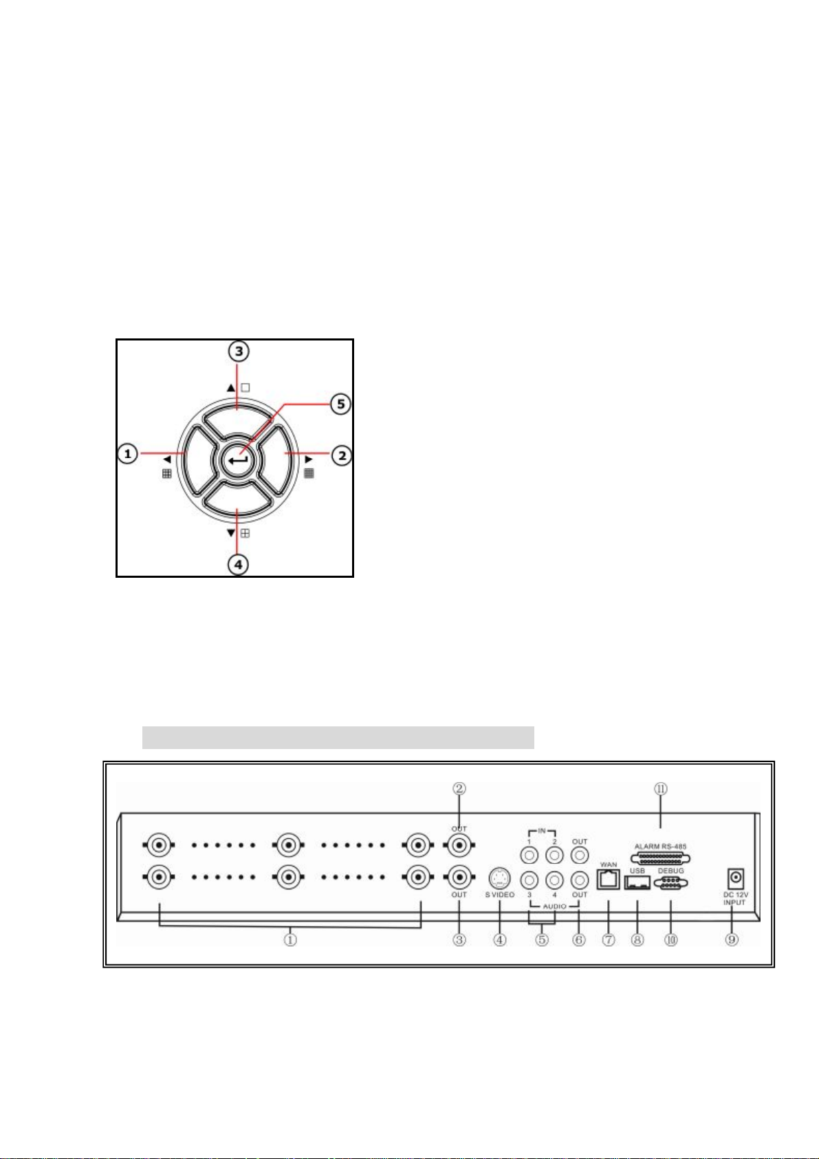
2.3 Channel Choosing Control Area
1. Nine pictures/left: Press this button to see nine pictures
display, re-press this button to see eight pictures. While
select menu items, press this button to move the cursor left
ward.
2. Sixteen picture/right: Press this button to see sixteen
pictures display, re-press this button to see thirteen
pictures. While selecting menu items, press this button to
move the cursor rightward.
3. Big picture/up: Press this button to see full screen, repress this button to see the next channel. While selecting
menu items, press this button to move up the cursor.
4. Four pictures/down: Press this button to see four pictures display , re-press this button will
display next four pictures. While selecting menu items, press this button to move down the cursor.
5. Enter: W hile sel ecting menu i tems, pr ess this button to select the item. W hile playing video,
press this button to pause the play, press play button to continue play.
3. REAR PANEL AND S YSTEM CONNECTION
8
Page 9
3.1 Back panel and connection terminals
Main
Assisant
S Video
Video In 16
Microphone
The power cable and input, outp ut signal term inals are all at the b ack of the machi ne, the
connection to monitor, camera etc equipments are all carried out through the terminals and
sockets on the back panel the back view of the machine is illustrated as below.
Each part of the back panel is illustrated as below:
1. Video input CH1-CH16 2.main output 3.assistant monitor 4.S-VIDEO 5.audio input 6.audio
output 7.net interface 8.USB port 9.power 10.debug port 11.Alarm and RS485 ,port define:
(1-12: sensor1-sensor12; 13, 20, 24, 25: GND, 14-17: sensor 13-sensor16, 18: RS485A 19:
RS485B, 21: COM 22: NC 23: NO)
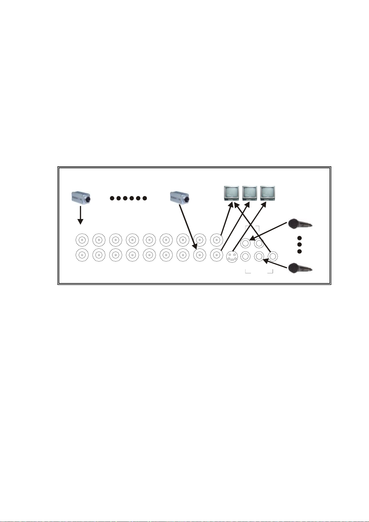
3.2 Video and Audio Connection
The DVR can support up to 16 cameras video input at the same time.
VideoIn1
Out
Out
Out
CH1
CH9
CH2
CH10
CH3
CH11
CH4
CH12
CH5
CH13
CH6
CH14
CH7
CH15
CH8
CH16
OUT
S VIDEOOUT
IN
21
OUT
3 4
AUDIO
The DVR can connect 4 channel’s audio input, but you can only select one for recording. To
display the D VR picture, the DVR video output signal should be transferred to your TV set or
monitor. Any TV set that has a “video input” terminal is suitable for displaying the image. The
figure above shows the video and audio signal line connecti on.
Notice: you can only connect one audio input at any one time, which means, if you
connect an audio input to CH1, you cannot connect any to CH2 through CH4.
3.3 Alarm Connection
The DVR can support up to 16-alarm input and 1 alarm output.
Alarm input: there are two types of alarm input.
1. Voltage output (5V and 0V)
A: In case sensor output high voltage (5V) normally and output low voltage when trigg
ered (0V), then users must set DVR as low voltage alarm.
B: In case sensor output low voltage (0V) normally and output high voltage when trigg
ered (5V), then users must set DVR as high voltage alarm.
Please refer to the picture below, channel 2 to channel 16 are the same as channel 1.
9
Page 10
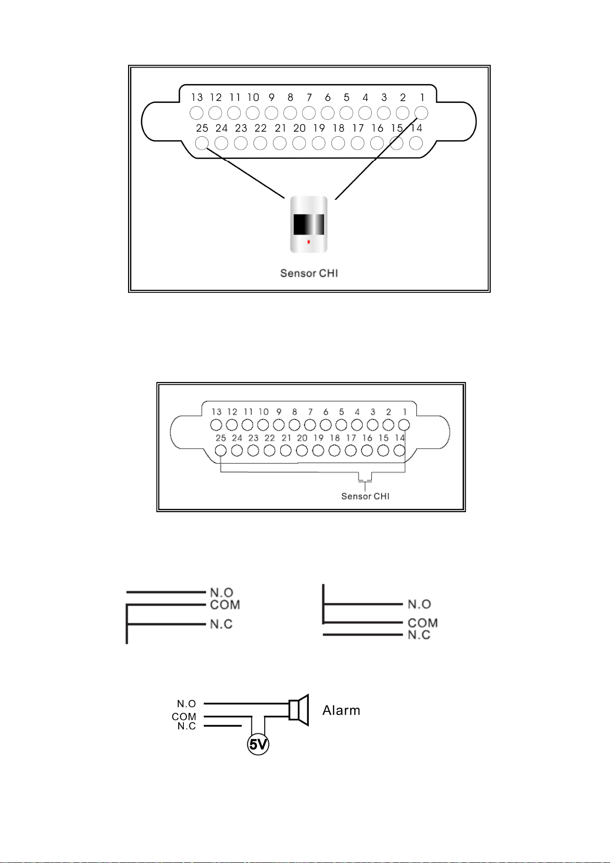
2. Open/Close output
A: N.O. Normal open, close when triggered. DVR must set as low voltage alarm.
B: N.C. Normal close, open when triggered. DVR must set as high voltage alarm.
Please refer to the picture below, channel 2 to channel 16 are the same as channel 1.
Alarm output:
There are three alarm output pin, the status of these pin are illustrated as below
Before Alarm After Alarm
There is an example for alarm output connection
10
Page 11
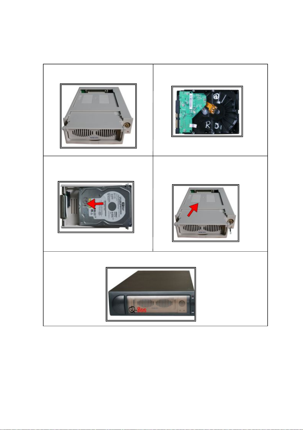
3.4 Hard Disk Connection
There are processing to install the hard disk.
Note: If the DVR comes with a HDD pre-installed then skip the following steps.
1. Pull out the hard drive rack from DVR
side panel.
3. Open the top cover of the drawer.
2. Connect the DATA cable & power cord.
4. Close the top cover of the drawer and
put the hard drive drawer back into the
DVR
5. Lock the hard drive draw by turning the key cl ockwise.
If you have another HDD, please jump that HDD to SLAVE, and open then machine, put the HDD
to the HDD rack, and then connect the power cord and DATA cable.
11
Page 12

4. REMOTE CONTROLLER
0 – 9, 10+: Select the channel (Full screen)
2x2: 2x2 Screen Modes
3x3: 3x3 Screen Modes
4x4: 4x4 Screen Modes
USB: USB Storage Backup
AUTO: Auto Sequence Mode
ZOOM: 2X Zoom
FREEZE: Freeze
DISPLAY: Hard Disk Information
MENU/EXIT: System Setup
SEARCH: Time Searc h, Event Search a nd Start Stop Searc h
ENTER: Enter Nex t Menu
REC: Record
WM: Watermark set
PTZ: Control Speed dome
5. SYSTEM SETUP
Before usi ng the video recorder, the first s tep i s t o set up the system acc or di ng to user’s needs;
otherwise the machine will run with the default settings.
5.1 SETUP MENU
When in s etup mode, press upward button or downward button, the cursor will move among
the settable items, continuous pressing will make the cursor move among the options one by
one, and it can recur. The selected one will display in yellow color.
While choosing digital fields, e.g. year, month, day, hour, minute, second etc, press
leftward button or rightward button, the cursor can move leftward or rightward among
The sever al digits of one fiel d, continuous p ressing w ill make i t move am ong digits one b y one,
and it can recur.
Please press leftward or rightward button to change the value that the cursor on,
Press “ENTER” button to enter sub menu and press menu button to return to previous menu.
Long press the m enu/s earch b utton o n th e ke yboar d or p ress the rem ote c ontrol ler to enter the
Setup Main Menu. You can show passw ord input box acc ording setting of password set. If you
fault password input 3-times, then you can’t enter the setup menu. Default password is “0000”,
12
Page 13
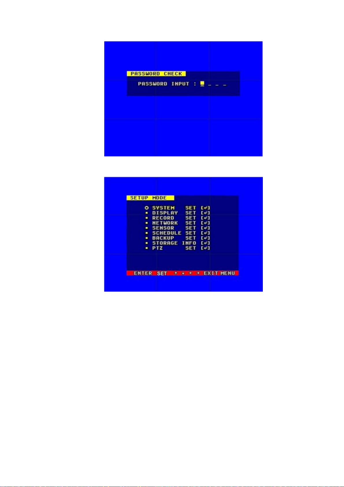
If you enter the correct password, the main menu will display ad below.
13
Page 14
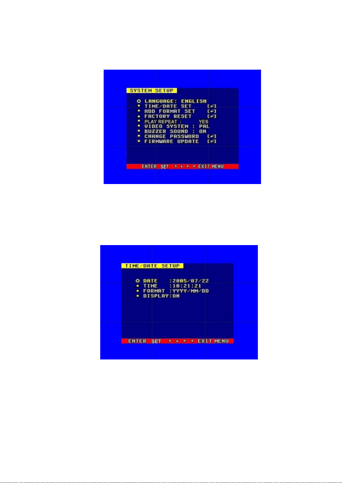
5.2 SYSTEM SETUP
Press “ENTER” button to enter sub menu
PLAY REPEAT: Set the Playback Repeat
VIDEO SYSTEM: Set the NTSC/PAL
BUZZER SOUND: Set the Buzzer On/Off
5.2.1 TIME/DATA SET
Set the date and time.
DATE: Set the date
TIME: Set the time
FORMAT: Set the tim e display form at (USA, EURO and Asia Users)
DISPLAY: Set the time display on/off
LOCAL: Set the time displ ay position
14
Page 15
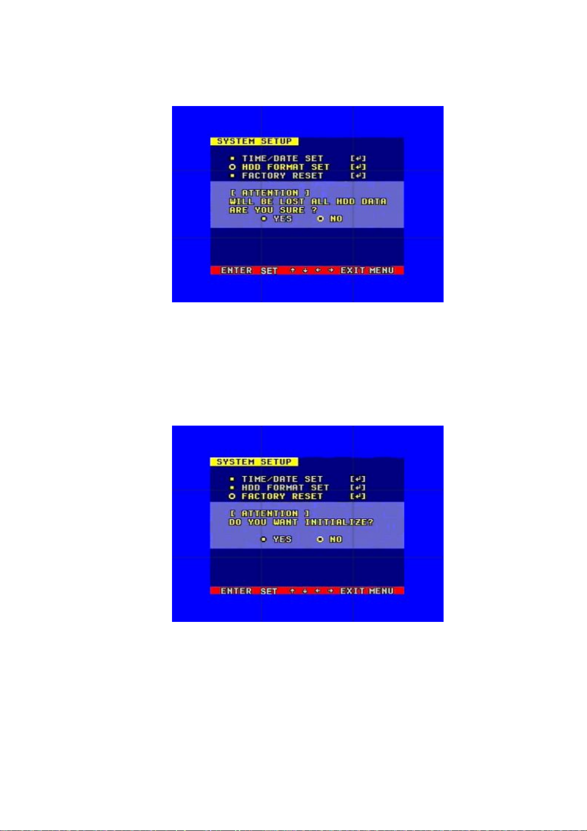
5.2.2 HDD FORMAT SET
Format the hard disk.
Select “YES”, to form at the hard disk. And all video on the HDD will los s.
5.2.3 FACTORY RESET
Initialize all the setup; the DVR will reset to factory default settings.
15
Page 16
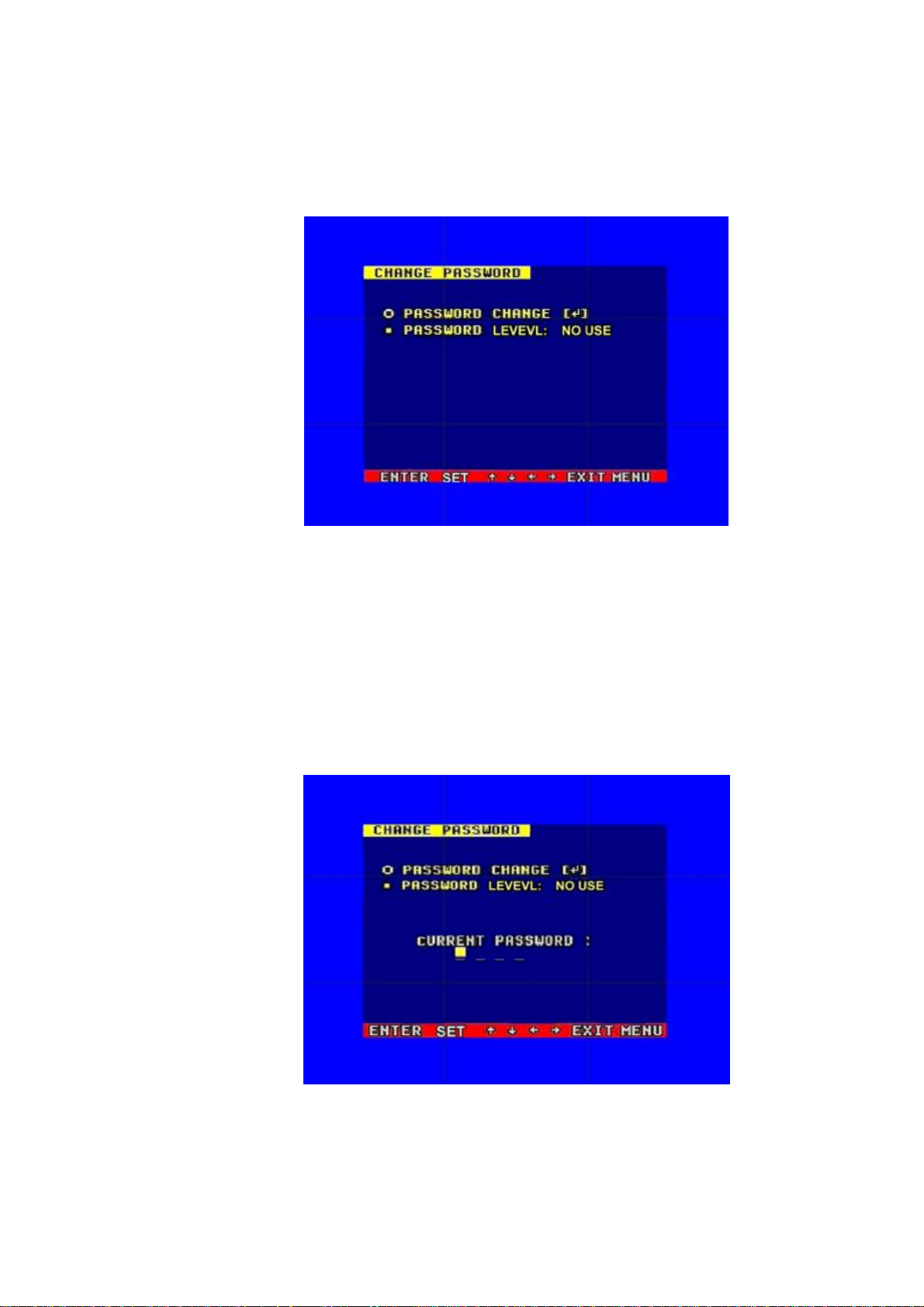
5.2.4 Change Password
When the c ursor moves to CHANGE PASSW ORD, please press the enter button, and the
Change Password window will appear.
Password Level: password type of the DVR, the DVR has various types of password:
SETUP: If set to “YES”, you have to input password to enter menu.
SYSTEM: If set to “YES”, you have to input password to boot the DVR.
ALWAYS: If set to “YES”, you have to input password to all operation.
If you select the Passwor d Change and press the Enter button, t he Passwor d change
window will display as below:
Please enter the current password, then input new password and confirm the password.
16
Page 17

5.2.5 Firmware Update
When the cur sor mov es to FIRMWARE UPDATE, please p ress enter butto n, and the firmware
update window will appear.
Update Method: There are two methods to update the DVR firmware, USB (for USB thumb
drives) and Network (not support)
USB update: cr eate a new f older nam ed “f irmw are” in the USB t hum b driv e’s r oot dir ector y, copy
the update f ile to the fol der, and p lug in the U SB th umb driv e. Enter the Fi rmw ar e Up date m enu,
select Update Start and press enter button, the system will start updating. When updating is
finished, the window below will be displayed, please manually reboot the DVR.
17
Page 18

5.3 DISPLAY SETUP
BOUND COLOR: Set the Color of Video Boundary (BLACK / W HITE / GRAY).
BLANK COLOR: Set the Background Color of Loss Video (BLACK / WHITE).
5.3.1 CAMERA NAME SET
When the cursor moves to Camera Name, please press the Enter button, the Camera Name
Setup window will appear.
Press the up or down button to select channels, press the Enter button to change the channel
name.
18
Page 19

Each chann el’s name i s a combi nation of six eight character s. Press up or dow n button t o
select each c har act er, pr ess LEFT or R IGHT button to modif y each char acter, and then press
enter button to save this name.
DISPLAY: if Display is set to “OFF”, the channel’s name will not display on the screen.
5.3.2 COLOR SET
When the cur sor moves to Color Set, please press the Enter b utton, the C ol or Setup w i ndow
will appear.
CON: picture contrast BRI: picture brightness
HUE: picture hue SAT: picture saturation
Press LEFT or RIGHT butto n to select CON/BRI/HUE/SAT, press UP or DOW N button to
change the value, if setup over, press UP or DOWN button to change channel.
19
Page 20

5.3.3. AUTO SEQUENCE SET
When the c ursor moves to Autoseq Set, p lease press enter button, the Aut o Sequence Setup
window will appear.
Press the UP or DOWN button to select channel, press LEFT or RIGHT button to change the auto
Sequence time.
5.4 RECORD SETUP
When the cursor moves to Record Set, then press the Enter button, the Record Setup window will
appear, which i s illust rated as below. Press UP or DOWN button to m ove the cur sor. Then press
the LEF T or R IGH T but ton to cha ng e the value. While the DVR is in recor di ng or p l a yback mode,
you cannot access this menu unless you stop record or play first.
OVER WRITE: if set to “YES”, the DVR will automatically overwrite the HDD from the
beginning when the HDD is full. If set to “NO”, the DVR will automatically stop recording when
the HDD is full. If there are t wo HDD i n the DVR, w hen the MASTER HDD is f ull, the v ideo
will stor e to the SLAVE HDD, and when the SLAVE HDD is also full , the DVR wi ll overwr ite
the MASTER HDD if set this to “YES”, otherwise it will stop recording.
20
Page 21

REC SPEED: the recor ding f rame r ate of the D VR, f actory defaul t setti ng is 30F /SEC under
NTSC (25F/ SEC under PAL). This m eans the DVR records the ev ents at the spee d of 30
shots of f r am es per second. The hi gher of the record f r am e rate, the m or e natural look w i ll be
displayed on th e scr een when you p layback the footage. Th e low er of the r ecord fr ame rate,
the more you ca n sav e the space on the har d di sk. The hi ghest f r ame r ate is 120F/SEC (PAL
is 100F/SEC) when the resolution is in CIF mode
REC QUALITY: There are four different video quality setti ngs: LOW, LOW+, HIGH, HIGH+.
The higher of the video quality, the clearer images you can get when you playback. The lower
of the video quality, the more you can save the space on the hard disk drive.
RESOLUTION: the r ecord pi ct ur e size of the DVR have two modes:CIF and F IELD, def aul t i s
CIF. In F IELD mode, t he recor ded pict ure is twice the size of that in C IF mode. I n CIF m ode
the REC speed is 120F/SEC NTSC (PAL is 100F/SEC) and the maximal REC speed in
FIELD mode is 60F/SEC NSTC (PAL is 50F/SEC).
PB SPEED: the frame rate of playback, default is AUTO, which means the same as record.
5.4.1 AUDIO CH SET
When the cur sor m oves to Audi o CH Set, press the Enter b utton, t he Audio C H Set w indow
will appear, as illustrated below.
There are four audio input channels, for each channel you can select anyone of the 8
channels. Although there are four audio input channels, you can only record from one
channel’s audio at the same time. To setting the audio correctly, you have to select one
channel within these four channels in the Audio Select menu.
21
Page 22

5.4.2 REC CH SET
When the cursor moves to REC ch Set, please press enter button, the REC ch setup window
will appear. This screen is different for CIF and FIELD modes . In FIELD mode, the window is
illustrated as below, press UP and DOWN buttons to select channel and press LEFT or
RIGHT button to change the setting, if the channel is set “OFF”, this channel will not record
when in recording mode. If the resolution is set to "CIF ", the REC ch Setup window can not
be setup.
5.4.3 RECORD LENGTH SET
To set the file package time in continuous time record mode
5.5 NETW ORK SETUP
When the c ursor m oves to Netw ork Set, p ress t he Enter b utton, an d the netw ork setup window
will appear. Please note if the N etviewer softw are is connected to the D VR. You cannot ac cess
this menu unless you close the Netviewer software.
22
Page 23

IP MODE: the DVR has 2 IP modes, STATIC IP and DHCP, if you select STATIC IP, you can set
the IP address manually, if you select DHCP mode, the DVR will automatically get the IP address.
For STATIC IP, press UP or DOWN button to m ove the cur sor among the di gits, you can pr ess
LEFT and RIGHT buttons to modify the digits, press enter to save you change.
WEB SERVER PORT: the WEB transmit port for data. Default is 0080.
NETWORK EN V: the DVR has thr ee types of different netw or k c onditions: LOCAL, EX TER_ LAN,
and EXTER_W AN. If in local network, please select LOCAL. If for internet use, please choos e
EXTER_LAN. If the internet condition is not very good, please select EXTER_WAN.
VIDEO PORT: the video transmit port for the computer. Default is 5000.
COMMAND PORT: the command transmit port for the computer. Default is 5001.
If you change any of the VIDEO PORT and COMMAND PORT or MAC address, you have to
restart the DVR before you use the “net viewer” softw are.
Notice: if you have changed the MAC address, you will not have access to the “MA
C ADDR SET” Option.
5.5.1. N/W ENABLE SET
When the cursor moves to N/W Enable, press the Enter button, and the N/W Enable setup
window will appear.
If one chann el her e set OF F, this channel w i l l not tr ansmit to the network, so i f you want to see a
channel from network, you must to set this channel ON.
23
Page 24

5.5.2. MAC SET
When the cursor moves to Mac Set then press the Enter button, the Mac Set window will appear.
If you hav e more than one DVR in a l ocal area network, you have to set each DVR to have a n
exclusiv e MAC addr ess, but rem ember that you have only one chance to modify the MAC
address, onc e you hav e c hanged th e M AC address , this m enu w il l not ap pear ag ain. If you w ant
to change t he MAC addr ess again, p lease load the factory s et, then you c an change the MAC
address. For MAC address, you’d better set the first two bytes to “00 00”, and change other bytes.
5.6 SENSOR SETUP
When the cur sor moves to Sensor Set, then p r ess the Enter b utton, t he s ens or set up w i ndow w ill
appear. Press UP or DOWN button to move the cursor. Press LEFT or RIGHT to change the
value.
24
Page 25

ALARM ENABLE: al arm trigger sw itch, can be set to off, N.C(normal cl osed) or N.O(norm al open).
If users set it to off, the DVR will ignore the alarm input.
MOTION ENABLE: Motion alarm switch, can be set to ON or OFF. If set to off, the DVR will ignore
the motion alarm.
MOTION LEVEL: m oti on sens iti vi ty lev el, i f the f igure in the p ictur e is s m all , please s et to hi g h or
very high, default is normal.
BUZZER TIME: buzzer sound time when there is a sensor or motion alarm.
SENSE RECTIME: when a motion or sensor alarm is triggered, the recording time of DVR, default
is 10 seconds.
Notice: Users should press the schedule button after setting up the parameters to activate
the settings.
5.6.1 Motion Detection settings
1) When surveying nearby objects (2-10 meters)
When in daytime, please set motion detection sensitivity to Normal level; when in night,
please set to low.
2) When surveying objects in 50-100 meters area
The objects 50- 100 m eters away will b e qui te smal l on the scree n. W hen in da ytime, p lease
set motion detection sensitivity to high level.
25
Page 26

When in night as below, please set to normal level.
Note: the above sugg est i ons are a guide only bas ed on testing i n a g eneral environment. Yo u
will need to sel ect the best par am eters accordi ng to the actual operation env i ronment you are
covering. Try different settings until you get the desired motion detection result.
5.6.2 MOTION AREA SET
Move the c ursor t o Moti on Area Set, then p ress the Enter button, an d the area se tup window
will appear. Press the up , down, left, right button to m ove the cursor and press the Enter
button to cha nge from detection ON to OFF. Press and hold the E nter button to c hange all
values to the same as the area you have selection.
If the area m ar ker i con is s et to yellow, thi s area i s m oni tored f or m otion detec tion, and i f the
icon is blue, motion sensing is disabled for that area.
26
Page 27

5.7 SCHEDULE SET
When the c ursor moves to Schedule Set, press the Enter button, and the schedule setup
window will appear.
You can change a recording schedule during a day by using this setup window.
Please note: Military time must be used.
START: start record time
STOP: stop record time
SCHEDULE ENABLE: must set to “on”, if want to enable schedule record function
Note: Manual record mode and schedule record mode (including motion detection
record mode, sensor record mode and time schedule record mode) can not be used at
the sam e tim e. Once the user selects S ched ul e r ecord m ode, m anu al recor d mod e w ill
disabled; once user select manual record mode, schedule record mode will be
disabled.
5.8 USB BACKUP
Set the USB BACKUP.
Plug in the USB device, and press “ENTER” button, you can see the below picture.
There are tw o typ es of back up m ode: STIL L and MOVIE , in S TILL m ode you ca n b ackup Pict ure
and in MOVIE mode you can backup video.
27
Page 28

5.9 STORAGE INFO
When the cur sor m ov es to Storage Inf o, p ress the Enter button, and the st orag e inf o wi ndow
will appear.
MODEL: Model Number of the Hard Disk
CAPACITY: Total capacity
USED SIZE: Space used
OVER WRITE: The number of times overwritten
5.10 PTZ SET
When the cursor moves to PTZ Set, press the Enter button, and the PTZ Set window will appear.
You m ust set the correct p rotocol so you can control a Pan Tilt c amera (Speed Dome) v ia the
DVR. Press the UP or DOWN button to move the cur sor, and press LEFT or RIGHT to change
the value.
28
Page 29

CHANNEL SEL: If you have a speed dome camera, select the channel which the camera is
connected to.
BAUD RATE: Changeable from 1200bps to 115200bps. The default value is 2400bps.
DOME ADDR: The a ddress of the speed dome camera, changeable from 0x00 to 0xff.
PROTOCOL: The protocol of speed dome camera: PELCO-D,PELCO-P,NEON,SAMSUNG
6. Quick User Guideline
6.1 Start the DVR
Before starti ng the DVR, p l ease make sur e all the i tems i n the “Security Notice
of this manual are fulfilled and that the input and output cables are all correctly connected.
Also ensure th e DVR ’s v ideo inp ut f ormat (N TSC/PAL) and the m oni tor ( NTSC/PAL) are both s et
to the same video standard. NTSC for USA & Canada, PAL for Australia, UK and most of Europe.
Fit the hard disk to t he remov able caddy and i nsert the rem ovable caddy i nto the h ousing, th en
lock it up (turn the hard di sk lock to the right) and connec t the power which will t hen boot the DVR
and it will start to work.
” at the beginning
6.2 Turn off the DVR
Only turn off the DVR w hen the system is inactive. D o not to turn off the DVR w hile playing or
doing the S ystem Setup. Turning off the D VR while recording may cause the r ecording to c or r up t,
and can cause the HDD to be unreadable in some cases.
Press the Record button to stop recording or press Stop button to stop playing or exit from
System Setup menu, then turn off the power.
If do not w ish us e the vi deo recorder f or a l ong time, you sho uld p ull out the p ower line fr om the
electrical outlet and store the unit where it will not be damaged.
6.3 Normal Recording
Connect the power to all related equipment; ensure that there is video input using direct
connection to your TV or VC R. Press the Di spl ay button to chec k spare spac e of the hard disk, i f
there is no t m uch s pace, p lease c onsi der ch ang ing your hard di sk fi rst or sel ect Overwri te mode.
Check recor di ng par ameter set up b ef or e r ecording; s elect video qual i ty, frame r ate. Note that you
cannot chang e recor d setti ng dur ing the p roces s of recor ding. M anual r ecording s are the norm al
recording conditi on. Under t he manual m ode (non-schedul e stat us) ,
pressing the Record button will record all channel’s video. Press the Record button to begin
recording , f our channel s w ill start sim ultaneous r eco r ding . W hile i n norm al r ecor di ng m ode, pr ess
the Record or Stop button, a nd e nter the r ig ht password, to stop recor ding . D uring the pr ocess of
recording if the hard di sk i s full and the system i s s et to au tomatic overwrite, the r ecording will not
be inter rupted b ut the DVR will automatical ly begi n to overwri te recorded v ideo from the ear liest
(oldest) recorded area. If the system is set to ov erwrite disab led, it wil l stop recordi ng once the
HDD is full.
29
Page 30

6.4 Alarm R ecording
Alarm recording is not started by manually pressing the Record button, it is automatically
activated once Schedule mode is enab l ed. Alarm recor di ng can be activated by alarm input signal
or moti on, if the connect i on of alarm i np ut equipm ent is c or r ect , s tabl e and reliab l e, and the alarm
settings ar e cor rect . For r ec ording to b e acti v ated by ex teri or inp ut si gnal or m otion d etecti on t h e
system m ust be set to Schedule M ode active and that period is set to “A” in Recor d Schedule
setup. You m ust al so set the m enu of Al arm Setup for ext erior inp ut alar m , and the alar m enabl e
setting of that channel must b e set to “ON ”. For Motion Al arm, t he motion enab le setting of that
channel m ust set “ON ”, and set the are a for m otion detec tion m ust be set. If Schedul e mode is
disabled the system will not start recording on alarm. Setting schedule on or off is achieved
through p r ess i ng the SCHEDULE button on t he front panel or r em ote, but not throug h the System
Setup m enu and wi ndow. W hen the unit is in Sche dule Mode act i ve, the character “S” w ill displ ay
on the sc r een. Alarm video recording can’ t be st op ped b y pressi ng the RECOR D or STOP button
while Schedul e M od e is acti ve. To ensure th at o nce Schedule Mo de is set to on that the sc h edul e
cannot be acc identally stop ped ther e is a passw ord pr otection to s top Schedul e Mode. You must
press the SC HEDU LE button th en enter the c orrect pass wor d to turn Sche dule Mod e off. C heck
Alarm Recording setup before recording; confirm the video quality and the frame rate, as the
record setti ng can’t be changed dur i ng the recording proces s. As long as th e alar m inp ut si g nal i s
correctl y set the alar m recor di ng will cont i nue d ur i ng the per i od of tim e set up by A/M REC TIME,
and when the outside the time period the alarm recording automatically stops.
6.5 Time Recording
Time recording starts and stops recor di ng automati cally according to the pre-arr anged time per i od.
It is ap plied to a f ixed ti metabl e, for example b usiness hours t im e recor ding (or outside business
hours tim e recording) w ith fixed start/s top time. To start the Time Recor ding function you must
have a r ecord schedule set up befor ehand. When thi s is done, pr ess the SCHEDU LE button on
the front panel to set schedule mode to on and the schedule symbol “S” will display on the screen.
The Time Recording mode will not work unless you activate Schedule Mode. To make Time
Recording mode activ e the system m ust b e set t o Schedul e Mode acti v e and that p eri od is set to
“T” in Record Schedule setup. In Time Recor d m ode, you m ust pr ess the SCHEDULE b utton t hen
enter the pass word to stop ti me recor di ng. Because Time recor ding is reliant on the system being
set with the correct time, you m ust adjust the tim e to your correct local time before using this
function.
6.6 Playback
Press the PLAY button and the system will b egi n to play the im ag es recorded fr om the start of the
most current recording.
If the recording is playing, press the PAUSE button to pause playing, press the PLAY button again
to resume normal play.
To use Fast Forwar d playing or Fast Backwar d playing , press the FW D or REW button whi le the
30
Page 31

recording is playing to see faster playback. Press the PLAY button to return to normal speed
playing from the current place.
Continuous p ressing of the FWD button wil l change the fast - forward between four l evels of speed
(X2, X4, X8, X16,) in sequence. Continuously pressing the REW button will change the fast
backward playback between four levels of speed (X2, X4, X8, X16) in sequence.
During playback mode, press the Single Frame Forward button to play a frame at a time, and hold
the button in to continuall y play one frame at time while the button is hold.
During p l ayback mode, pr ess the Single F r am e Rewi nd button to pl ay b ack a frame at a time, and
hold the button in to continually play one frame at tim e while the button is hold.
Press the PLAY button again to resume normal playback speed, or press the STOP button to stop
playing.
6.7 Search Play
Press the search button to display the Search play window on the screen.
TIME SEARCH: search recording by the time entered.
EVENT SEARCH: search recording by event list.
RECORD SEARCH: search recording by segment.
Press the U P or DOWN button to move c ursor, then press Enter button to ent er sub m enu you
have highlighted. Press the Search button again to quit from search menu.
31
Page 32

6.8 Time Search
Move the c ursor to Time Sear ch, then p ress the E nter button and the Tim e search w indow will
appear, which is illustrated as below.
The red block below the number means there is recorded video at that time.
Press the LEFT and RIGHT buttons to move the cursor along the year, month, day, hour and
minutes.
Please note : You can only vi ew footage that has been r ecorded. Therefore you m ust select time
and dates that have a red block below them.
6.9 Event Search
Move the cur sor to Event Search, and then p ress the Enter b utton, the ev ent sear ch w indow will
appear, which is illustrated as below.
There are four types of event on this list: MOTION, ALARM, SCHEDULE and NETWORK.
MOTION means motion triggered alarm r ecor ding .
ALARM means external sensor trigger ed alarm recor ding.
SCHEDU LE means scheduled tim e recordi ng .
NETWORK means network activated recording.
Press the U P and DOWN buttons to m ove the cursor al ong the event l ist, and p ress the Ente r
button to play the segment you selected. Press the search button to return to the Search menu.
32
Page 33

If you w ant t o se arch from M ASTER HD D to SLAVE HDD , p ress the SERACH button, a nd then
press Enter button. Press the Menu button to exit.
6.10 Record Search
Move the c ur sor to the Record Search, p r ess the Enter button, and t he r ecor d search window wi l l
appear, which is illustrated as below.
All recor ded segments are di splayed here, p ress the up or down button to m ove
the cursor al ong the s egment l i st , press left or r ig ht buttons to see p r evious or next
page, press the Enter button to play the segment you selected. Press search
button again to return to the Search Play menu.
33
Page 34

If you w ant to change i t from the MASTER HD D to the SLAVE HDD, p ress the SEARC H button,
then press Enter button. Press the Menu button to exit.
6.11 USB Backup
If you want to use this function, the first step is to format USB device with “FAT” system on your
computer.
NOTE: the DVR doesn’t support “FAT32” file system .
Plug in the USB device, go to the menu of Backup set, check whether the USB device was
detected, and there is enough free space of the USB device, select the backup mode, then
completel y exit the menu system. USB backup is available only in playb ack m ode.
If you select ed “STI LL” for the back up mode, p ress the U SB button and an “S” wi ll appear on the
screen. W hen it disap pears, the back up of the pi cture is fini shed, and you can u n-plug the U SB
device out and see the picture on a com p uter w ith the netviewer softw are.
If you select “MOVIE” for the backup mode, press and hold the USB button until the “A” appears on
the screen, press the USB button again to select the end of the backup video. This may take a little
time, and m ake sur e the USB d evice has enoug h free space, i f the “ A” disap pear s, the back up is
ok, and you can view the video on a computer with netviewer software.
NOTE: if you backup still picture, please choose full picture display.
We recommend using high quality USB thumb drives that we provide
34
Page 35

6.12 USB Update
Using your PC to create a f ol der cal l e d “ f i rmw ar e” i n the r oot di r ect ory of your USB memor y sti ck ,
copy the update f iles t o th e fol der. Plug th e USB de vice i nto t he D VR, g o to th e m enu of B ackup
set, check that whether the USB device was detected, go to the Firmware Update menu and
select USB m ethod, move to Update Start and pr ess Enter b utton and th e up date w il l start. If you
see screen below, update was successful. Then reboot the DVR.
NOTE: Do not shut down the DVR when the DVR is updating, it may damage the system.
6.13 Zoom Operation
In shift mode, press zoom button, the DVR will be in zoom mode, which is illustrated as below.
Press upward, downward, leftward or rightward to move the zoom area, and then press enter
button to zoom, press zoom button again to cancel zoom operation.
35
Page 36

6.14 Information Display
In shift mode, press display button, the main information of the DVR will display on screen.
HDD SIZE: the si ze of the hard disk
HDD USED: the used space of the hard disk.
HDD READ: cur rent HDD address f or playback
OVERWRITE: overwrite time of the HD D
NETWORK IP: IP a ddress of the DVR.
REC LIST: number of record list
EVENT LIST: number of event list
REC OVER: record list overwrite or not
EVENT OVER: event list overwrite or not.
S/W VER: software version
6.15 PTZ Operation
This DVR can control all speed domes which are connected to the DVR.
To control the speed dom e, m ake sure al l the l ines are cor rectl y connected, f irst you must set the
right protocol, b aud r ate, and speed dome’s address for each speed dome, please r efer to protocol
set. For exam ple, you connect t he first speed dome to channel one, you should m ake s ur e that t h e
baud rate, the p r otoc ol , and speed dome’s address i s t he same as the speed dome you connect t o
the channel. Pr ess the P TZ b utton on the front pan el or remote c ontroll er, “PTZ” will b e disp layed
on the scree n, then select 1 to 16 t o choose PTZ c hannel, t he channel number w ill be disp layed
after “PTZ”, please refer to the picture below:
36
Page 37

You can pr ess up , down, left, or rig ht buttons to m ove the s peed dom e, and pr ess the Enter
button to stop . If you press the Ir is button, th e character “Iris” w ill app ear on the screen, p lease
refer to the p ict ure bel ow, then you can p ress the “ ADD” and “ DEC” b utton to chang e th e Ir is, the
same to control the focus, zoom, and speed, also press enter button to stop.
Note: W hen DVR is in PTZ mode, “REC” button is used as “ZOOM” ; “PLAY” button is used
as “IRIS”; “REW” button is used as “FOCUS”; “FWD” button is used as “SPEED”. “ADD” and
“DEC” buttons are used to adjust the value.
Press the PTZ button one more time to exit from PTZ control.
37
Page 38

6.16 REMOTE CONTROLLER
REC: Start or stop recording
SCHEDULE: Start Schedule recording function
0~9: Select channel or input password
2x2: Display Quad mode on screen
3x3: Display 9-channel cameras on screen
4x4: Display all 16-channel cameras on screen
AUTO: Same with “Auto” button on DVR keyboard
DISPLAY: Same with “Display” button on DVR keyboard
MENU: Same with “MENU” button on DVR keyboard
W/M: Same with “W/M” button on DVR keyboard
SEARCH: Same with “Search” button on DVR keyboard
CH +-: Change channel
SET+-: Select channel, address, or speed while in PTZ function
Forward button
Backward button
: Move one frame picture forward in Pause mode
: Move one frame picture backward in Pause mode
ZOOM: Same with “Zoom” button on DVR keyboard
FREEZE: Same with “Freeze” button on DVR keyboard
7. USING THE NETWORK VIEWER
Using the net viewer software, you can view the DVR through Int ernet or Intranet, also, you can view
and backup the video data on the HDD through a computer. Open the software; you will see the
window below:
38
Page 39

7.1 Setting
Please click
Enter the IP address and click “OK” button.
button, you will see the window below:
7.2 Viewer connect
Press
bottom, you can see the login box. Enter the correct password and click ok to login DVR.
<Connect success> <Connect fail >
39
Page 40

7.3 Live play
Click play button to see live picture,
7.4 Playback
After clicki ng “Playback” tab, net search window will display. Fi rst, you have t o select the HDD of t he
DVR. Click t he “Get rec ord list” or “Get event li st”, if the DVR has rec ord li st, you can see the window
below:
Double click the record list; you can see the pl ayback video. The event list operation is the same as
record list operation.
40
Page 41

7.5 Scandisk
Connect the HDD that used in the DVR to a PC and then select Scandisk, Scandisk window wil l displa
y, click
and select one HDD, then you can play all the video on the HDD.
<Scandisk Menu>
7.6 File Play
Press “FilePlay” button, you can see the below picture, press the “open” button play the video file on th
e com puter.
< Fileplay Menu>
1. Pressing the button, you can
record the video by you computer.
2. Pressing the button, you can See
the below picture.
3. Pressing the button, you can
stop the record DVR.
4. Pressing the button, you can
remote the DVR record to the HDD.
41
Page 42

7.7 Save to AVI
To record t he video to your PC’s HDD with “ .avi” file system , just click" AVI" button, and the following
window will pop-up
Here, select t he record channel and cli ck "+" icon to define the fil e nam e and sav e path and click "ok"
to sta rt the AVI save.
Re-press the "AVI" button to stop the AVI record.
42
Page 43

7.8 Save to DVR
To record the vi deo stream t o your PC’s HDD , just click " DVR" button and the video stream will be
saved in the directory that you set (the default directory is c:\DVR\)
Note: to play the file saved to DVR, just click "FilePlay" tab to open it.
7.9 PTZ Control
To control the speed dome, just click "UP","DOWN","LEFT" and "RIGHT" buttons to control speed
dome's horizontal or v ertical position. Also, you can control speed dome's Iris, Focus and Zoom , j ust
to select the item and then click the "+" and "-" icons.
43
Page 44

8. Main standard & parameter chart
Item Specification
Compress ed picture M-JPEG
Video signal NTSC/PAL
Video input
Video output
Audio input
Audio output
Alarm i np ut 16
Alarm outp ut 1
Record tim e 18-1680 hours/ 40G
Electron clock Year/Month/D ay; Hour/Minute/Seco nd
Secrete functi on
Update
Power sour ce
Conposite:1.0Vp -p/75Ω,BNC×16
Conposite:1.0Vp -p/75Ω,BNC×2 S- VIDEO
-8Db 22KΩ,RCA connector×4
-8Db 3KΩ,RCA connector×2
Passwor d protection
USB
DC12V 5A
Work temperature:+5℃~+70℃;humidity:<90%
Envir onm ent temperature
store temperature-20℃~+70℃;humidity:<95%
weight 5.3kg(include power supply)
Exterior size 430mmX400mm X90mm
44
Page 45

9. Trouble shooting guide
Q. What kind of camera should I buy for this DVR?
A. Any BNC or RCA interface indoor/outdoor/infrared camera will work with the DVR. It doesn’t matter
whether it’s a color or black/white camera. However, web cameras that require a USB interface are not
compatible with the DVR.
Q. What kind of alarm device should I buy for DVR?
A. Most sound alarms are compatible with our DVR.
Q. I can’t turn on DVR.
A. Make sure that the power cord is plugged in correctly and t he power light on DVR front panel is on.
Q. I see nothing but a blue screen after I turn on DVR.
A. Check the camera input and video output connection on DVR back panel. If you can’t find problem
with these connections, check whether the camera power cable is firmly connected. Make sure the
system format for NTSC and PAL is right.
Q. Can I prevent other people from stopping the recording while I am gone?
A. If the DVR is in schedule or recording mode, set password “on” in menu setup, no one can change
the set unless he has the ri ght password.
Q. How can I erase all data on the hard disk drive?
A. Select “HDD Format Set” option in the menu.
Q. Can my desktop PC read the video data on hard disk drive i n DVR?
A. Yes, you can use our software to read all video data on hard disk.
Q. What happens if I install my PC hard disk drive into the DVR?
A. You can use a PC hard disk drive in the DVR. However, once it runs in DVR, it will delete any PC
operation system and files on the hard disk drive.
Q. What kind of hard disk driv e should I purchase to make the DVR run?
A. Any PC compatible IDE, ATA hard disk drive will work.
Q. What is the capacity to record?
A. Up to a year with two 120 GB HDD at the lowest quality setting when set at 1 frame per second.
Q. Does this DVR come with a remote control either hardwire or wireless?
A. Yes, there is a remote control come with the DVR.
45
Page 46

Q. Why cannot I access Time/Date Set, HDD Format Set, Record Set menu?
A. Pl ease stop record or play before you access these menu.
Q. Why cannot I access Network Set menu?
A. Please stop the connection of t he PC View soft from Internet before you access Network Set menu.
Q. I press record button, but the DV R does not start rec ording, why?
A. Press di splay button to see if there i s a hard disk detected, also if the DVR is in schedule mode
(there is a “S” on the screen i n yell ow), you c annot start recordi ng by pr ess record butt on, you have to
press schedule button again to cancel schedule mode.
Q. I press record button while recording, but the DVR does not stop recording, why?
A. If the DVR is recording in schedule mode (there is a “S” on screen), you cannot stop recording
unless you quit schedul e mode first. Press schedule button to cancel schedule mode.
Q. There is a movement, but the DVR does not start recording.
A. Make sure t he m ot i on enabl e of that channel i s on, the area set i s ok, t he A/M rec tim e is not set t o
off, and the DVR is in schedule mode. Otherwise set the motion level to HIGH or VERY HIGH.
Q. When the net work connection bet ween DVR and client computer is cut off, why the DVR hal ts and
clock stops?
A: In c ase network is cut off abnormally, DVR machine wi ll halts for 20 seconds without response to
any operation of pressing f ront panel buttons. 20 seconds lat er, it will restore normal state, but the icon
that shows network status won't disappear i n 10 minutes and in this period client computer cannot
connect to the DVR or enter network menu.
Q. I long press the “Menu/ search” button, but it do not di splay password menu, and directly enter the
menu, why do not I need a password?
A. If the password level setup in Password Setup i s “NO USE”, you do not need a password to enter
the menu, if you want to need a password when enter m enu setup, j ust change the password l evel t o
“SETUP”.
Q. I press the menu button, but it does not display the password menu to enter menu, why?
A. To enter menu, you have to long press the “Menu/ search” button, if you j ust press this butt on, you
will see the search menu.
46
Page 47

Q. How do I change the On Screen Display (OSD) language on the DVR?
A. You can change t he OSD language f rom the def ault English to Germ an, French, Itali an, Polish, or
Spanish by following the steps below.
To change the OSD language, enter t he menu system by pressing t he MENU button on the front of the
DVR and correctly input your password.
Highlight the “SYSTEM SET” option, and press the ENTER button.
Select “ LANGUAGE SET” and press the ENTER button.
Press the LEFT or RIGHT buttons to change t he l anguage and press the ENT ER but ton to selec t your
language.
Now fully exit the menu system and restart your DVR.
10. Record Time Table
Rec rate field/sec Picture quality Resolution Recording time
60 fps Very high 720 47 hours
60 fps Low 720 125 hours
120 fps Normal 360 47 hours
1 fps Normal 720 4500 hours
Note: The above figu res are from our test with a 250GB hard disk. Just for users’ reference.
Different d efinition and stabilization (objects’ movement) of the images will make some kin d of
different results.
47
Page 48

11. Int ernet View/Pla yback C onfigurati ons
11.1 About Networks
Users will generally use the following network t ypes and hardware:
1): Local Area Network (LAN): An internal network usually operated via a hub, a switch, or a router and
will usually operate within an office or household via wireless or Ethernet cable connec tions.
2): DSL (or ADSL): T his is a specif i c type of broadband I nternet acc ess obtained by conn ect ing a DSL
or ADSL modem (or modem /router) to a norm al telephone cable, and sett ing up an Internet ac count
with an Internet Service Provider (ISP) such as AT&T or AOL.
3): Port Forwardi ng: This allows ex ternal connec tions to pass through security sett ings on rout ers and
firewall devices. Ports need to be allows in, and then directed to the specific IP address of the
computer or device that the connection is intending to reach.
4): Router: Thi s is a device that connects 2 separate net works (most commonly a LAN to the Int ernet)
and comes with bui lt in security options and allows multiple devices to connect to a LAN and gain
Internet access (if the router is connected to a modem).
11.2 Network Configurations
After connecting to Internet, DVR users should make the following configurations to make remote
view/playback.
1): When in LAN, network administrators should open the following ports for specifics computers:
5000- 5002. Please make sure that the other services don't use the sam e ports.
2): In case users use ADSL network and the surveillance system computer connect to the ADSL
MODEM, then the ports hav e all opened by default. If not, please close fire wall by guidance of the
ADSL MODEM user's manual.
48
Page 49

3): In case you connect t o Internet by proxy server, users should ut ilize port mapping software and
open ports 500 0, 5001, and 5002 f or the surveillance com puter.
4): In case users connect to Internet by router, then users should add the IP address of the
surveill ance computer and open t he abov e mentioned ports in DMZ setup or Virtual Serv er setup (t he
names maybe different in various other kinds of routers) of the router.
5): For CABLE MODEM type and ADSL MODEM type, the configurations are similar to the images
below:
49
Page 50

As ADSL and CABLE MODEM net work users usually use dynam ic IP address, so once t he MODEM
restarts, the IP addresses will change. For this situation, users should apply for DNS services.
To use the Swann DVRs with remote viewing capabilities you may have to “open“ ports on your
Windows® Firewall, your Software Firewall or on the Broadband Router/Modem that you use to
connect to the Internet. Please consult the documentation or help fil es on the relevant software or
system for i nstructions on how to do this. To successfully access your cam eras from the I nternet you
will need to have allowed access to and from the following ports from an outside connection. This
process is also called “Port Forwarding” or creating a “Virtual Server” connection.
For more information on Port Forwarding, please visit www.portforward.com
Once you have c orrectly forwarded the ports, pl ease check to see what your ext ernal IP address is
(this cannot start wit h 192.168.x.x). You can check this by going to htt p://www.whati smyip.com (note:
you must do this on the server machine to find the correct external IP of the router.)
You may also hav e to place the IP address of the Swann DVR in the “DMZ” of your Fi rewall to enable
the remote viewing int erface. Information on how to do this should be detail ed in the documentation
covering operation of your Firewall.
As ADSL and CABLE MODEM network users usually use a dynam ic IP address, once the MODEM
restarts, the IP addresses can change. Users can opt for a static IP address which does not change by
contacting their ISP. Otherwise users can apply for a DNS service through www.no-ip.com or
www.dyndns.com
50
Page 51

Q-SEE Product Warranty
Thank you for choosing our products.
All of our products users have a conditional free warranty repair service for
hardware within 12 months starting from purchase date, and a free exchange service
within one month (valid for manufacturing defects). Permanent upgrading service is
provided for the software.
Liability Exclusions:
Any product malfunction, abnormalities in operation or damage caused by
following reasons are not within the free service scope of our company. Please select
payable service.
(1) Equipment damage caused by improper operation
(2) Improper environment and conditions in/on which the equipment operates, e.g.,
improper power, environment temperature, humidity and lightening strike etc. that
cause equipment damage.
(3) Damage caused by acts of nature: earthquake and fire etc.
(4) Equipment damage caused by the maintenance of personnel not authorized by
our company.
(5) Product sold over 12 months ago.
In order to provide various services to you, please complete registration
procedure after you purchase the product. Cut off or copy User ’s Information Card
and fax or mail it to us after the card is filled in. You can also register the product by
going to the www.q-see.com website and clicking on the Register link.
If you have questions:
Contact Us:
Mailing Address: Customer Service:
DPS Inc. Phone: 877-998-3440 x 538
8015 E. Crystal Dr Email: cs@dpsi-usa.com
Anaheim, CA 92807
Website: Tech Support:
http://www.q-see.com Phone: 877-998-3440 x 539
Fax: Email: ts@dpsi-usa.com
714-998-3509
51
Page 52

Customer Information Card
User’s Name Mr./Mrs.
Company
Name
Postal
Address
Postal code
Phone
Number
E-mail
Model Number
of Product
Serial Nu mber
of Product
Purchase Date
Distributor
The material in this document is the intellectual property of our compa ny.
No part of this manual may be reproduced, copied, translated, transmitted, or published in any form
or by any means without our company’s prior written permission.
1. Our products are under continual improvement and we reserve the right to make changes without
notice. But no guarantee is given as to the correctness of its contents.
2. We do not accept any responsibility for any harm caused by using our product.
3. The product picture may differ from the actual product, which is only for your reference. The
accessories will probably be different according to the different selling areas. For details of accessories,
please refer to your local distributor.
Copyright reserved
52
 Loading...