

Page 1
MVI56-S3964R
ControlLogix Platform
Siemens 3964R Protocol
User Manual
April 17, 2008
Page 2

Please Read This Notice
Successful application of this module requires a reasonable working knowledge of the Rockwell Automation
ControlLogix hardware, the
used. For this reason, it is important that those responsible for implementation satisfy themselves that the
combination will meet the needs of the application without exposing personnel or equipment to unsafe or
inappropriate working conditions.
This manual is provided to assist the user. Every attempt has been made to ensure that the information
provided is accurate and a true reflection of the product's installation requirements. In order to ensure a
complete understanding of the operation of the product, the user should read all applicable Rockwell
Automation documentation on the operation of the Rockwell Automation hardware.
Under no conditions will ProSoft Technology be responsible or liable for indirect or consequential damages
resulting from the use or application of the product.
Reproduction of the contents of this manual, in whole or in part, without written permission from ProSoft
Technology is prohibited.
Information in this manual is subject to change without notice and does not represent a commitment on the
part of ProSoft Technology Improvements and/or changes in this manual or the product may be made at any
time. These changes will be made periodically to correct technical inaccuracies or typographical errors.
MVI56-S3964R Module and the application in which the combination is to be
Warnings
UL Warnings
A Warning - Explosion Hazard - Substitution of components may impair suitability for
Class I, Division 2.
B Warning - Explosion Hazard - When in Hazardous Locations, turn off power before
replacing or rewiring modules.
Warning - Explosion Hazard - Do not disconnect equipment unless power has been
switched off or the area is known to be nonhazardous.
C Suitable for use in Class I, division 2 Groups A, B, C and D Hazardous Locations or
Non-Hazardous Locations.
ATEX Warnings and Conditions of Safe Usage:
Power, Input, and Output (I/O) wiring must be in accordance with the authority having
jurisdiction
A Warning - Explosion Hazard - When in hazardous locations, turn off power before
replacing or wiring modules.
B Warning - Explosion Hazard - Do not disconnect equipment unless power has been
switched off or the area is known to be non-hazardous.
C These products are intended to be mounted in an IP54 enclosure. The devices shall
provide external means to prevent the rated voltage being exceeded by transient
disturbances of more than 40%. This device must be used only with ATEX certified
backplanes.
D DO NOT OPEN WHEN ENERGIZED.
Page 3

Electrical Ratings
Backplane Current Load: 800 mA @ 5 V DC; 3mA @ 24V DC
Operating Temperature: 0 to 60°C (32 to 140°F)
Storage Temperature: -40 to 85°C (-40 to 185°F)
Shock: 30g Operational; 50g non-operational; Vibration: 5 g from 10 to 150 Hz
Relative Humidity 5% to 95% (non-condensing)
All phase conductor sizes must be at least 1.3 mm(squared) and all earth ground
conductors must be at least 4mm(squared).
Markings:
II 3 G 0C <=Ta<= 60C EEx nA IIC T4 DEMKO 07ATEX0710717X
Battery Life Advisory
All modules in the MVI series use a rechargeable Lithium Vanadium Pentoxide battery to
backup the 512K SRAM memory, real-time clock, and CMOS. The battery should last for
the life of the module.
The module must be powered for approximately twenty hours before it becomes fully
charged. After it is fully charged, the battery provides backup power for the CMOS setup
and configuration data, the real-time clock, and the 512K SRAM memory for
approximately 21 days.
Before you remove a module from its power source, ensure that the battery within the
module is fully charged. A fully charged battery will hold the BIOS settings (after being
removed from its power source) for a limited number of days (15 for the PC56). When
the battery is fully discharged, the module will revert to the default BIOS settings.
Note: The battery is not user replaceable.
ProSoft® Product Documentation
In an effort to conserve paper, ProSoft Technology no longer includes printed manuals
with our product shipments. User Manuals, Datasheets, Sample Ladder Files, and
Configuration Files are provided on the enclosed CD and are available at no charge from
our web site:
Printed documentation is available for purchase. Contact ProSoft Technology for pricing
and availability.
Asia Pacific: +603.7724.2080
Europe, Middle East, South Africa: +33.5.34.36.87.20
Latin America: +1.281.298.9109
North America: +1.661.716.5100
http://www.prosoft-technology.com
Page 4

Your Feedback Please
We always want you to feel that you made the right decision to use our products. If you have suggestions,
comments, compliments or complaints about the product, documentation or support, please write or call us.
ProSoft Technology
1675 Chester Avenue, Fourth Floor
Bakersfield, CA 93301
+1 (661) 716-5100
+1 (661) 716-5101 (Fax)
http://www.prosoft-technology.com
Copyright © ProSoft Technology, Inc. 2000 - 2008. All Rights Reserved.
MVI56-S3964R User Manual
April 17, 2008
PSFT.S3964R.MVI56.UM.08.04.17
ProSoft Technology ®, ProLinx ®, inRAx ®, ProTalk® and RadioLinx ® are Registered Trademarks of
ProSoft Technology, Inc.
Page 5

Contents TMVI56-S3964RT ♦ TControlLogix PlatformT
TSiemens 3964R ProtocolT
Contents
PLEASE READ THIS NOTICE................................................................................................................2
Warnings............................................................................................................................................ 2
Battery Life Advisory.......................................................................................................................... 3
ProSoft® Product Documentation .....................................................................................................3
Your Feedback Please ......................................................................................................................4
GUIDE TO THE MVI56-S3964R USER MANUAL..................................................................................7
1 START HERE....................................................................................................................................9
1.1 System Requirements.................................................................................................................9
1.2 Package Contents.....................................................................................................................10
1.3 Install ProSoft Configuration Builder Software.......................................................................... 10
1.4 Setting Jumpers ........................................................................................................................12
1.5 Install the Module in the Rack...................................................................................................12
1.6 Connect your PC to the Processor ...........................................................................................14
1.7 Open the Sample Ladder Logic ................................................................................................ 15
1.7.1 To Determine the Firmware Version of your Processor............................................................. 15
1.7.2 Select the Slot Number for the Module...................................................................................... 16
1.7.3 Configuring RSLinx.................................................................................................................... 17
1.8 Download the Sample Program to the Processor..................................................................... 18
1.9 Connect your PC to the Module................................................................................................ 19
2 INSTALLING AND CONFIGURING THE MODULE.......................................................................21
2.1 Installation Instructions..............................................................................................................21
2.1.1 Module Data Object................................................................................................................... 22
2.2 ProSoft Configuration Builder ...................................................................................................26
2.2.1 Set Up the Project .....................................................................................................................26
2.2.2 Set Module Parameters............................................................................................................. 28
2.3 [Module] ....................................................................................................................................30
2.3.1 Module Name ............................................................................................................................ 30
2.4 [Backplane 56] ..........................................................................................................................30
2.4.1 Block Transfer Size ................................................................................................................... 30
2.4.2 Status Interval............................................................................................................................ 30
2.5 [3964R Port x] ........................................................................................................................... 30
2.5.1 Enable ....................................................................................................................................... 31
2.5.2 Baud Rate ................................................................................................................................. 31
2.5.3 Parity ......................................................................................................................................... 31
2.5.4 Data Bits.................................................................................................................................... 31
2.5.5 Stop Bits .................................................................................................................................... 31
2.5.6 RTS On ..................................................................................................................................... 31
2.5.7 RTS Off ..................................................................................................................................... 31
2.5.8 Use CTS Line ............................................................................................................................ 31
2.5.9 Swap .........................................................................................................................................31
2.5.10 Priority ....................................................................................................................................... 32
2.5.11 Protocol .....................................................................................................................................32
2.5.12 ACK Delay................................................................................................................................. 32
2.5.13 Setup Attempts .......................................................................................................................... 32
2.5.14 Transmit Attempts ..................................................................................................................... 32
2.6 Download the Project to the Module ......................................................................................... 32
3 LADDER LOGIC .............................................................................................................................35
3.1 Introduction ...............................................................................................................................35
3.1.1 Explanations About the Example Programs .............................................................................. 35
3.1.2 The 3964R Communication Program ........................................................................................ 36
ProSoft Technology, Inc. Page 5 of 78
April 17, 2008
Page 6

TMVI56-S3964RT ♦ TControlLogix PlatformT Contents
TSiemens 3964R ProtocolT
3.2 Commands ............................................................................................................................... 36
3.2.1 9998 Warm Boot ....................................................................................................................... 36
3.2.2 9999 Cold Boot.......................................................................................................................... 36
4 DIAGNOSTICS AND TROUBLESHOOTING................................................................................. 37
4.1 Reading Status Data from the Module ..................................................................................... 37
4.1.1 Required Hardware ................................................................................................................... 37
4.1.2 The Configuration/Debug Menu ................................................................................................ 38
4.1.3 Main Menu................................................................................................................................. 40
4.1.4 Database View Menu ................................................................................................................ 43
4.1.5 Backplane Menu........................................................................................................................ 45
4.1.6 Protocol Serial 3964R Menu......................................................................................................46
4.2 LED Status Indicators............................................................................................................... 47
4.2.1 Clearing a Fault Condition ......................................................................................................... 48
4.2.2 Troubleshooting......................................................................................................................... 48
5 REFERENCE.................................................................................................................................. 51
5.1 Product Specifications .............................................................................................................. 51
5.1.1 Features and Benefits ............................................................................................................... 51
5.1.2 General Specifications .............................................................................................................. 51
5.1.3 Hardware Specifications............................................................................................................ 52
5.1.4 Functional Specifications........................................................................................................... 52
5.2 Functional Overview ................................................................................................................. 53
5.2.1 Products in the Environment .....................................................................................................53
5.2.2 3964R Protocol Overview.......................................................................................................... 53
5.2.3 General Concepts ..................................................................................................................... 54
5.2.4 Communications........................................................................................................................ 58
5.2.5 Job Processing.......................................................................................................................... 61
5.3 Cable Connections ................................................................................................................... 61
5.3.1 RS-232 Configuration/Debug Port............................................................................................. 61
5.3.2 RS-232 ...................................................................................................................................... 64
5.3.3 RS-232 Cable............................................................................................................................ 64
5.3.4 RS-422 ...................................................................................................................................... 64
5.3.5 DB9 to RJ45 Adaptor (Cable 14)............................................................................................... 65
5.4 Reference Documents.............................................................................................................. 65
5.5 Status Data ............................................................................................................................... 65
5.6 Error Codes .............................................................................................................................. 66
6 SUPPORT, SERVICE & WARRANTY ........................................................................................... 67
6.1 How to Contact Us: Sales and Support.................................................................................... 68
6.2 Return Material Authorization (RMA) Policies and Conditions................................................. 68
6.2.1 All Product Returns ................................................................................................................... 69
6.3 Procedures for Return of Units Under Warranty ...................................................................... 69
6.4 Procedures for Return of Units Out of Warranty ...................................................................... 70
6.4.1 Un-repairable Units ................................................................................................................... 70
6.4.2 Purchasing Warranty Extension ................................................................................................ 71
6.5 LIMITED WARRANTY.............................................................................................................. 71
6.5.1 What Is Covered By This Warranty ........................................................................................... 71
6.5.2 What Is Not Covered By This Warranty..................................................................................... 72
6.5.3 DISCLAIMER REGARDING HIGH RISK ACTIVITIES .............................................................. 73
6.5.4 DISCLAIMER OF ALL OTHER WARRANTIES......................................................................... 73
6.5.5 LIMITATION OF REMEDIES**.................................................................................................. 73
6.5.6 Time Limit for Bringing Suit ....................................................................................................... 73
6.5.7 No Other Warranties ................................................................................................................. 74
6.5.8 Intellectual Property................................................................................................................... 74
6.5.9 Additional Restrictions Relating To Software And Other Intellectual Property........................... 74
6.5.10 Allocation of risks ...................................................................................................................... 74
6.5.11 Controlling Law and Severability ............................................................................................... 75
INDEX.................................................................................................................................................... 77
Page 6 of 78 ProSoft Technology, Inc.
April 17, 2008
Page 7
Start Here TMVI56-S3964RT ♦ TControlLogix PlatformT
TSiemens 3964R ProtocolT
Guide to the MVI56-S3964R User Manual
Function Section to Read Details
Introduction
(Must Do)
Verify Communication,
Diagnostic and
Troubleshooting
Reference
Product Specifications
Functional Overview
Glossary
Support, Service, and
Warranty
Index
→
→
→
→
Start Here (page 9)
Verifying
Communication
(page 47)
Diagnostics and
Troubleshooting
(page 37)
Reference (page
51)
Functional
Overview
Product
Specifications
(page 51)
Support, Service
and Warranty
(page 67)
(page 53)
This Section introduces the customer to the
module. Included are: package contents,
system requirements, hardware installation,
and basic configuration.
This section describes how to verify
communications with the network. Diagnostic
and Troubleshooting procedures.
These sections contain general references
associated with this product, Specifications,
and the Functional Overview.
This section contains Support, Service and
Warranty information.
Index of chapters.
ProSoft Technology, Inc. Page 7 of 78
April 17, 2008
Page 8

TMVI56-S3964RT ♦ TControlLogix PlatformT Start Here
TSiemens 3964R ProtocolT
Page 8 of 78 ProSoft Technology, Inc.
April 17, 2008
Page 9
Start Here MVI56-S3964RT ♦ TControlLogix PlatformT TSiemens 3964R ProtocolT
1 Start Here
In This Chapter
System Requirements .............................................................................9
Package Contents .................................................................................10
Install ProSoft Configuration Builder Software....................................... 10
Setting Jumpers ....................................................................................12
Install the Module in the Rack ...............................................................12
Connect your PC to the Processor ........................................................14
Open the Sample Ladder Logic............................................................. 15
Download the Sample Program to the Processor.................................. 18
Connect your PC to the Module ............................................................19
Installing the MVI56-S3964R module requires a reasonable working knowledge
of the Rockwell Automation hardware, the
application in which they will be used.
Caution: It is important that those responsible for implementati on can complete the
application without exposing perso nnel, or equipment, to unsafe or inappropr iate working
conditions. Safety, quality and experience are key factors in a successful installation.
1.1 System Requirements
The MVI56-S3964R module requires the following minimum hardware and
software components:
Rockwell Automation ControlLogix™ processor, with compatible power
supply and one free slot in the rack, for the
module requires 800mA of available power.
Rockwell Automation RSLogix 5000 programming software version 2.51 or
higher.
Rockwell Automation RSLinx communication software
Pentium® II 450 MHz minimum. Pentium III 733 MHz (or better)
recommended
Supported operating systems:
o
Microsoft Windows XP Professional with Service Pack 1 or 2
o
Microsoft Windows 2000 Professional with Service Pack 1, 2, or 3
o
Microsoft Windows Server 2003
128 Mbytes of RAM minimum, 256 Mbytes of RAM recommended
MVI56-S3964R Module and the
MVI56-S3964R module. The
ProSoft Technology, Inc. Page 9 of 78
April 17, 2008
Page 10

MVI56-S3964RT ♦ TControlLogix PlatformT Start Here
TSiemens 3964R ProtocolT
100 Mbytes of free hard disk space (or more based on application
requirements)
256-color VGA graphics adapter, 800 x 600 minimum resolution (True Color
1024
× 768 recommended)
CD-ROM drive
HyperTerminal or other terminal emulator program.
Note: You can install the module in a local or remote rack. For remote rack installation, the modul e
requires EtherNet/IP or ControlNet communication with the processor.
1.2 Package Contents
The following components are included with your MVI56-S3964R module, and
are all required for installation and configuration.
Important: Before beginning the installati on, please verify that all of the following items ar e
present.
Qty. Part Name Part Number Part Description
1
1 Cable
3 Cable
2 Adapter 1454-9F
1
MVI56S3964R
Module
ProSoft
Solutions
CD
MVI56-S3964R Siemens 3964R Protocol
Cable #15, RS232
Null Modem
Cable #14, RJ45 to
DB9 Male Adapter
cable
For RS232 Connection to the CFG Port
For DB9 Connection to Module's Port
Two Adapters, DB9 Female to Screw Terminal.
For RS422 or RS485 Connections to Port 1 and 2
of the Module
Contains sample programs, utilities and
documentation for the
MVI56-S3964R module.
If any of these components are missing, please contact ProSoft Technology
Support for replacement parts.
1.3 Install ProSoft Configuration Builder Software
You must install the ProSoft Configuration Builder (PCB) software in order to
configure the
ProSoft Configuration Builder from the ProSoft Technology web site.
To install ProSoft Configuration Builder from the ProSoft Web Site
1 Open your web browser and navigate to http://www.prosoft-
technology.com/pcb
2 Click the
Configuration Builder.
Page 10 of 78 ProSoft Technology, Inc.
MVI56-S3964R module. You can always get the newest version of
Download Here link to download the latest version of ProSoft
April 17, 2008
Page 11
Start Here MVI56-S3964RT ♦ TControlLogix PlatformT
TSiemens 3964R ProtocolT
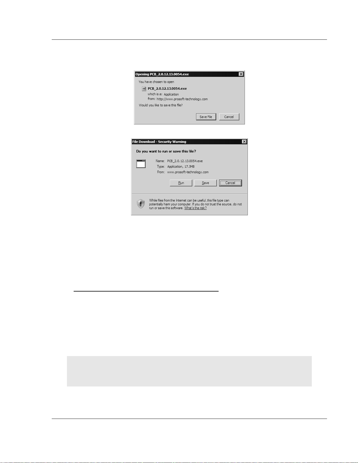
3 Choose "Save" or "Save File" when prompted. The following illustrations
show the file download prompt for two of the most common web browsers.
4 Make a note of the location where you saved the file, for example "Desktop",
or "My Documents", so you can start the installation program.
5 When the download is complete, locate and open the file, and then follow the
instructions on your screen to install the program.
If you do not have access to the Internet, you can install ProSoft Configuration
Builder from the ProSoft Solutions CD-ROM, included in the package with your
MVI56-S3964R module.
To install ProSoft Configuration Builder from the CD-ROM
1 Insert the ProSoft Solutions CD-ROM into the CD drive of your PC. Wait for
the startup screen to appear.
2 On the startup screen, click
Product Documentation. This action opens an
explorer window.
3 Click to open the
Utilities folder. This folder contains all of the applications
and files you will need to set up and configure your module.
4 Double-click the
ProSoft Configuration Builder Setup program and follow the
instructions on your screen to install the software on your PC.
Note: Many of the configuration and maintenance procedures use files and other utilities on the
CD-ROM. You may wish to copy the files from the Utilities folder on the CD-ROM to a convenient
location on your hard drive.
ProSoft Technology, Inc. Page 11 of 78
April 17, 2008
Page 12
MVI56-S3964RT ♦ TControlLogix PlatformT Start Here
TSiemens 3964R ProtocolT
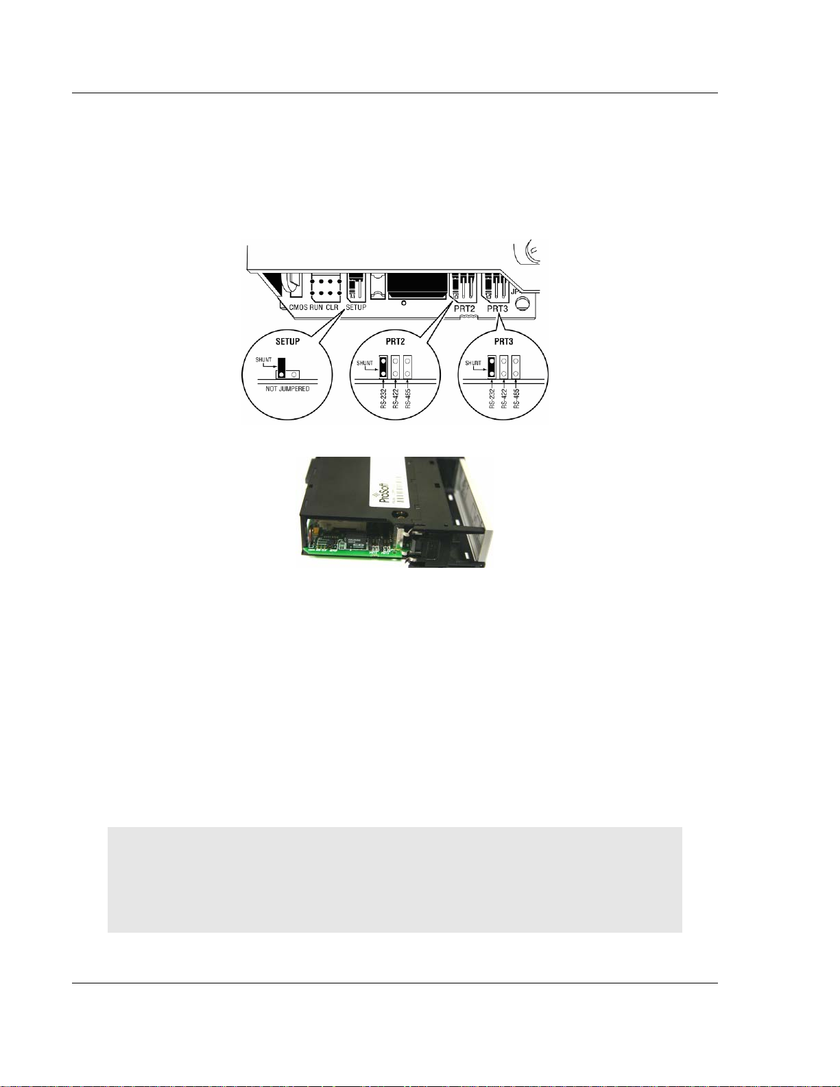
1.4 Setting Jumpers
If you use an interface other than RS-232 (default), you must change the jumper
configuration to match the interface. There are three jumpers located at the
bottom of the module.
The following illustration shows the MVI56-S3964R jumper configuration:
1 Set the PRT 2 (for application port 1) and PRT 3 (for application port 2)
jumpers for RS232, RS422 or RS485 to match the wiring needed for your
application. The default jumper setting for both application ports is RS-232.
2 The Setup Jumper acts as "write protection" for the module's flash memory.
In "write protected" mode, the Setup pins are not connected, and the
module's firmware cannot be overwritten. Do not jumper the Setup pins
together unless you are directed to do so by ProSoft Technical Support.
1.5 Install the Module in the Rack
If you have not already installed and configured your ControlLogix processor and
power supply, please do so before installing the
your Rockwell Automation product documentation for installation instructions.
Warning: You must follow all safety instructions when installing this or any other electronic
devices. Failure to follow safety procedures could result in damage to hardware or data, or even
serious injury or death to personnel. Refer to the documentation for each device you plan to
connect to verify that suitable safety procedures are in place before installing or servicing the
device.
MVI56-S3964R module. Refer to
Page 12 of 78 ProSoft Technology, Inc.
April 17, 2008
Page 13
Start Here MVI56-S3964RT ♦ TControlLogix PlatformT
TSiemens 3964R ProtocolT
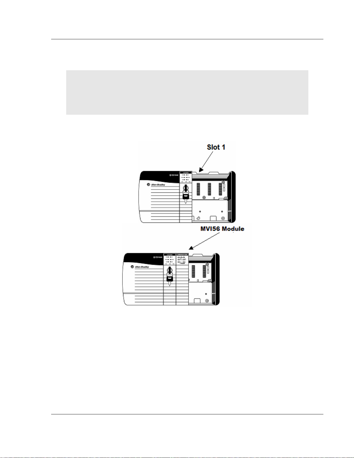
After you have checked the placement of the jumpers, insert
MVI56-S3964R into
the ControlLogix chassis. Use the same technique recommended by Rockwell
Automation to remove and install ControlLogix modules.
Warning: When you insert or remove the module while backplane power is on, an electrical arc
can occur. This could cause an explosion in hazardous location installations. Verify that power is
removed or the area is non-hazardous before proceeding. Repeated electrical arcing causes
excessive wear to contacts on both the module and its mating con nector. Worn contacts may
create electrical resistance that can affect module operation.
1 Turn power OFF.
2 Align the module with the top and bottom guides, and slide it into the rack
until the module is firmly against the backplane connector.
3 With a firm but steady push, snap the module into place.
4 Check that the holding clips on the top and bottom of the module are securely
in the locking holes of the rack.
5 Make a note of the slot location. You will need to identify the slot in which the
module is installed in order for the sample program to work correctly. Slot
numbers are identified on the green circuit board (backplane) of the
ControlLogix rack.
6 Turn power ON.
ProSoft Technology, Inc. Page 13 of 78
April 17, 2008
Page 14
MVI56-S3964RT ♦ TControlLogix PlatformT Start Here
TSiemens 3964R ProtocolT
Note: If you insert the module improperly, the system may stop working, or may behave
unpredictably.
Note: If you are installing MVI56-S3964R with other modules connected to the PCI bus, the
peripheral modules will not have holdi ng clips. Make sure all of the modules are alig ned with their
respective slots before you snap them into place.
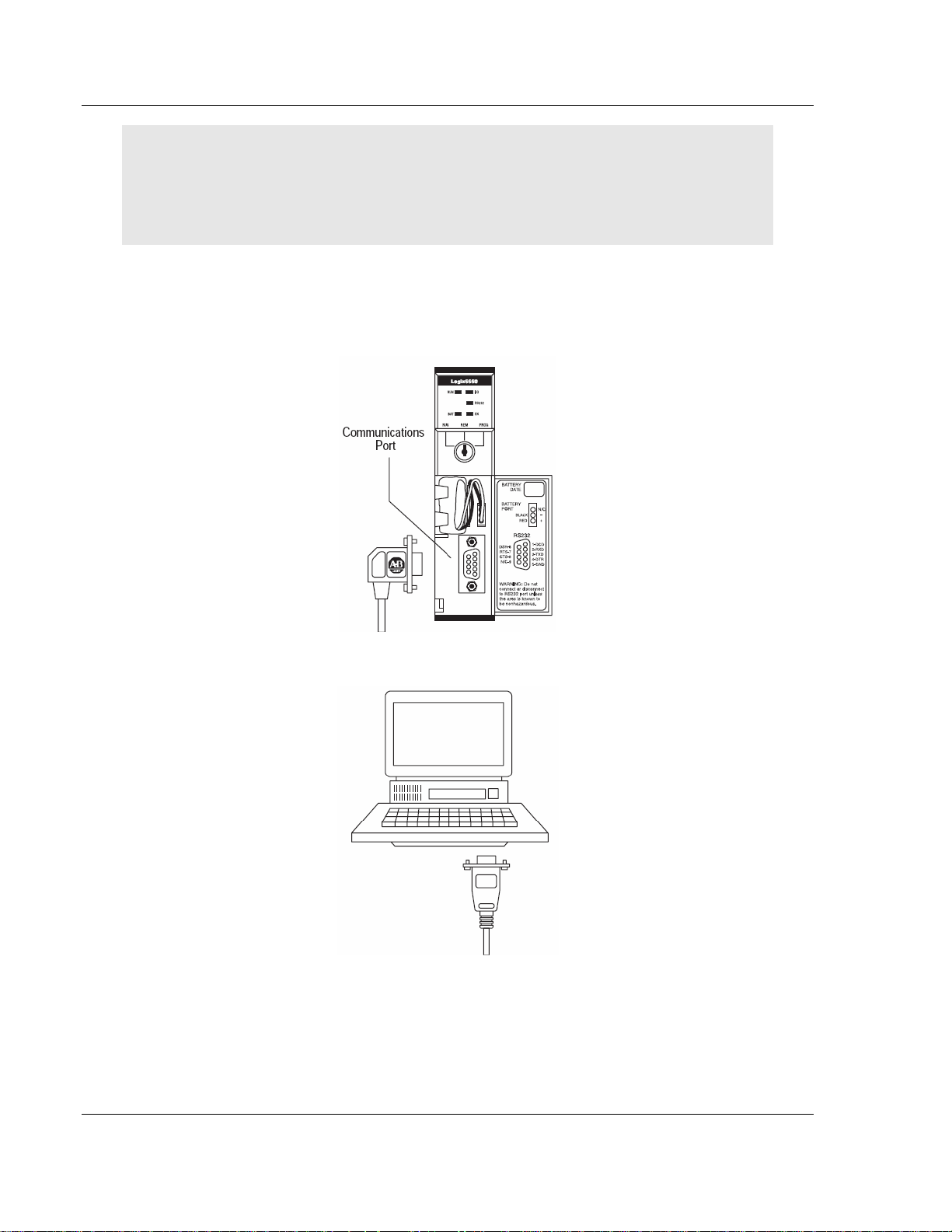
1.6 Connect your PC to the Processor
1 Connect the right-angle connector end of the cable to your controller at the
communications port.
2 Connect the straight connector end of the cable to the serial port on your
computer.
Page 14 of 78 ProSoft Technology, Inc.
April 17, 2008
Page 15
Start Here MVI56-S3964RT ♦ TControlLogix PlatformT
TSiemens 3964R ProtocolT
1.7 Open the Sample Ladder Logic
The sample program for your MVI56-S3964R module includes custom tags, data
types and ladder logic for data I/O and status monitoring. For most applications,
you can run the sample ladder program without modification, or, for advanced
applications, you can incorporate the sample program into your existing
application.
The inRAx Solutions CD provides one or more versions of the sample ladder
logic. The version number appended to the file name corresponds with the
firmware version number of your ControlLogix processor. The firmware version
and sample program version must match.
1.7.1 To Determine the Firmware Version of your Processor
Important: The RSLinx service must be installed and running on your computer in order for
RSLogix to communicate with the processor. Refer to your RSLinx and RSLogix documentation for
help configuring and troubleshooting these applications.
1 Connect an RS-232 serial cable from the COM (serial) port on your PC to the
communication port on the front of the processor.
2 Start RSLogix 5000 and close any existing project that may be loaded.
3 Open the Communications menu and choose
establish communication with the processor. This may take a few moments.
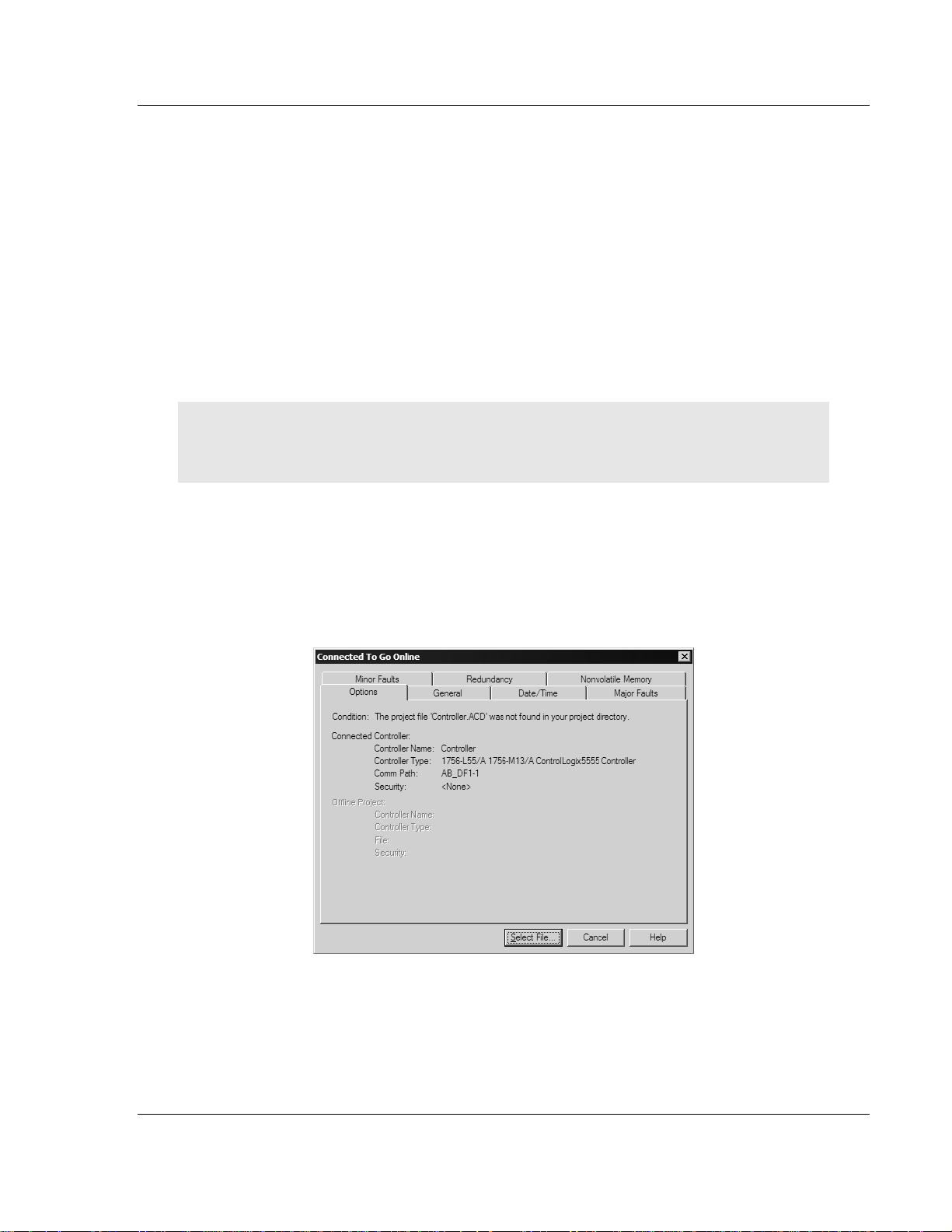
4 When RSLogix has established communication with the processor, the
Connected To Go Online dialog box will open.
Go Online. RSLogix will
ProSoft Technology, Inc. Page 15 of 78
April 17, 2008
Page 16
MVI56-S3964RT ♦ TControlLogix PlatformT Start Here
TSiemens 3964R ProtocolT
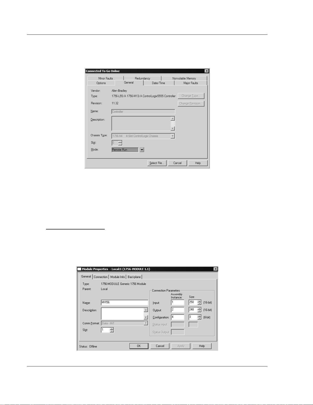
5 On the Connected To Go Online dialog box, click the General tab. This tab
shows information about the processor, including the Revision (firmware)
version. In the following illustration, the firmware version is 11.32
1.7.2 Select the Slot Number for the Module
The sample application is for a module installed in Slot 1 in a ControlLogix rack.
The ladder logic uses the slot number to identify the module. If you are installing
the module in a different slot, you must update the ladder logic so that program
tags and variables are correct, and do not conflict with other modules in the rack.
To change the slot number
1 In the Controller Organization list, select the module [1] 1756-MODULE
MVI56, and then click the right mouse button to open a shortcut menu.
2 On the shortcut menu, choose
Properties dialog box.
Properties. This action opens the Module
Page 16 of 78 ProSoft Technology, Inc.
April 17, 2008
Page 17
Start Here MVI56-S3964RT ♦ TControlLogix PlatformT
TSiemens 3964R ProtocolT
3 In the
Slot: field, use the spinners on the right side of the field to select the
slot number where the module will reside in the rack, and then click OK.
RSLogix will automatically apply the slot number change to all tags, variables
and ladder logic rungs that use the MVI56-S3964R slot number for computation.
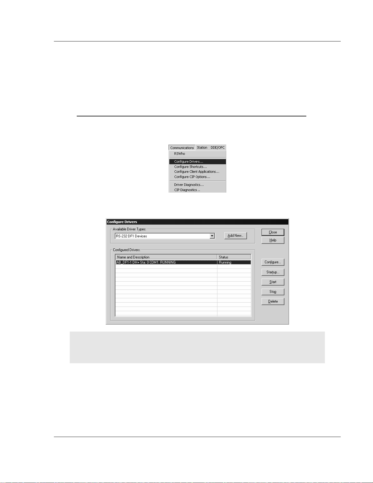
1.7.3 Configuring RSLinx
If RSLogix is unable to establish communication with the processor, follow these steps:
1 Open RSLinx.
2 Open the Communications menu, and choose Configure Drivers.
This action opens the Configure Drivers dialog box.
Note: If the list of configured drivers is blank, you must first choose and configure a driver from the
Available Driver Types list. The recommended driv er type to choose for serial communication with
the processor is "RS-232 DF1 Devices".
ProSoft Technology, Inc. Page 17 of 78
April 17, 2008
Page 18
MVI56-S3964RT ♦ TControlLogix PlatformT Start Here
TSiemens 3964R ProtocolT
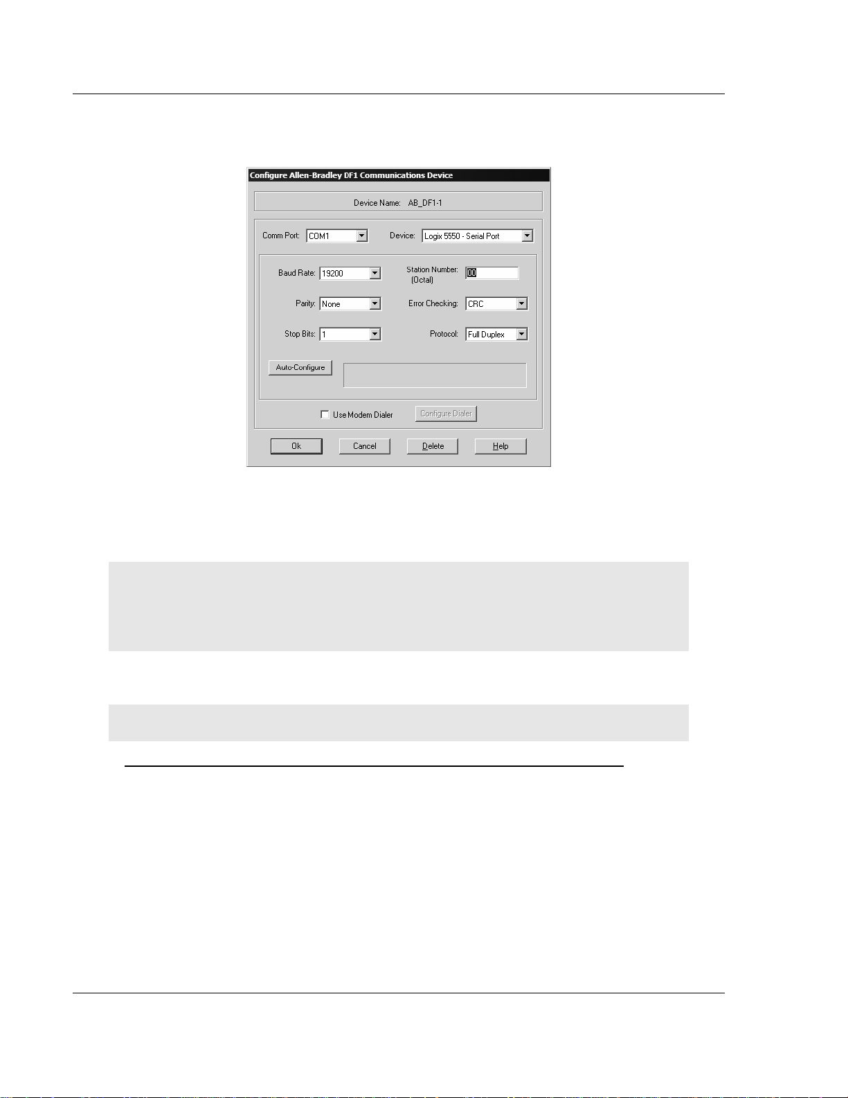
3 Click to select the driver, and then click Configure. This action opens the
Configure Allen-Bradley DF1 Communications Device dialog box.
4 Click the Auto-Configure button. RSLinx will attempt to configure your serial
port to work with the selected driver.
5 When you see the message "Auto Configuration Successful", click the OK
button to dismiss the dialog box.
Note: If the auto-configuration procedure fai ls, verify that the cables are connected correctly
between the processor and the serial p ort on your computer, and then try again. If you are still
unable to auto-configure the port, refer to your RSLinx documentation for further troubleshooti ng
steps.
1.8 Download the Sample Program to the Processor
Note: The key switch on the front of the ControlLogix module must be in the REM position.
To download the sample program from RSLogix 5000 to the ControlLogix processor
1 If you are not already online to the processor, open the Communications
menu, and then choose Download. RSLogix will establish communication
with the processor.
Page 18 of 78 ProSoft Technology, Inc.
April 17, 2008
Page 19
Start Here MVI56-S3964RT ♦ TControlLogix PlatformT
TSiemens 3964R ProtocolT
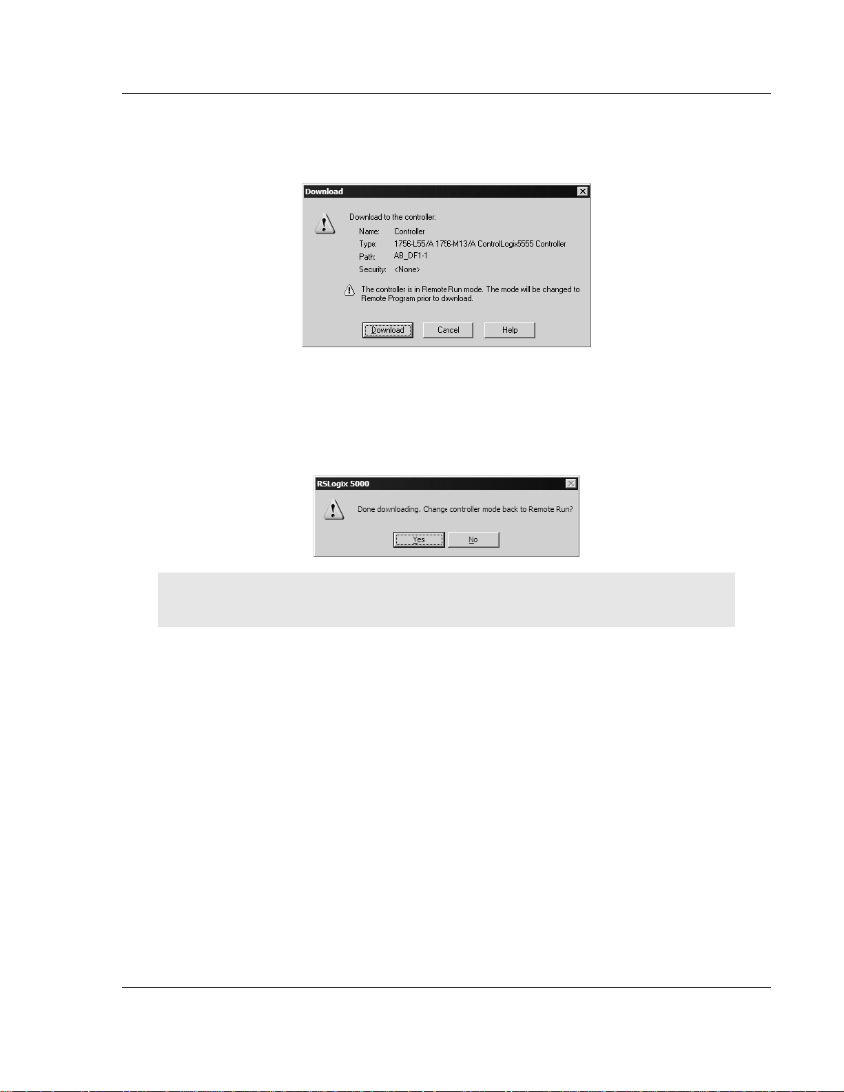
2 When communication is established, RSLogix will open a confirmation dialog
box. Click the Download button to transfer the sample program to the
processor.
3 RSLogix will compile the program and transfer it to the processor. This
process may take a few minutes.
4 When the download is complete, RSLogix will open another confirmation
dialog box. Click OK to switch the processor from Program mode to Run
mode.
Note: If you receive an error message during these steps, refer to your RSLogix documentation to
interpret and correct the error.
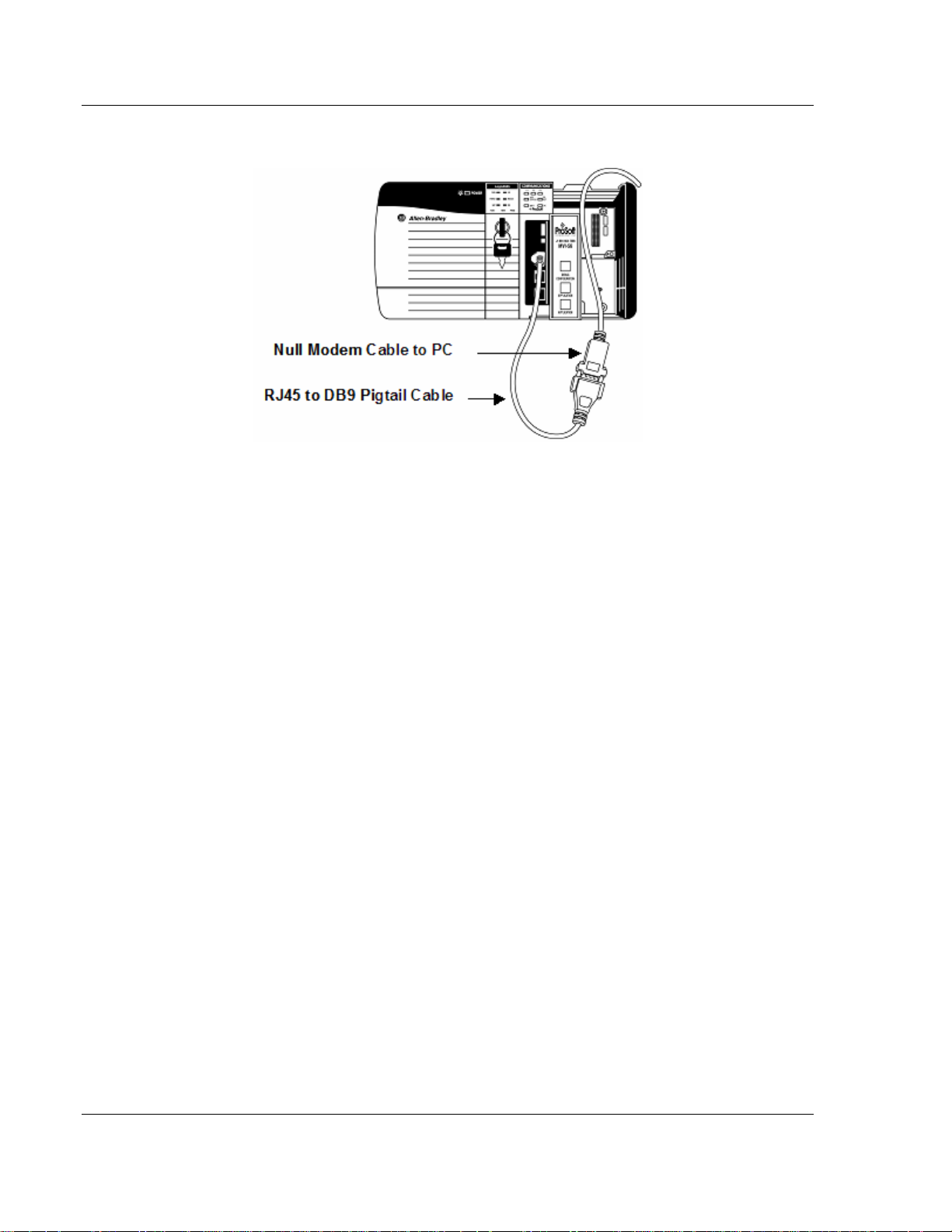
1.9 Connect your PC to the Module
With the module securely mounted, connect your PC to the
Configuration/Debug port using an RJ45-DB-9 Serial Adapter Cable and a Null
Modem Cable.
1 Attach both cables as shown.
2 Insert the RJ45 cable connector into the Configuration/Debug port of the
module.
ProSoft Technology, Inc. Page 19 of 78
April 17, 2008
Page 20
MVI56-S3964RT ♦ TControlLogix PlatformT Start Here
TSiemens 3964R ProtocolT
3 Attach the other end to the serial port on your PC or laptop.
Page 20 of 78 ProSoft Technology, Inc.
April 17, 2008
Page 21

Installing and Configuring the Module MVI56-S3964RT ♦ TControlLogix PlatformT
TSiemens 3964R ProtocolT
2 Installing and Configuring the Module
In This Chapter
Installation Instructions .......................................................................... 21
ProSoft Configuration Builder ................................................................26
[Module]................................................................................................. 30
[Backplane 56]....................................................................................... 30
[3964R Port x] .......................................................................................30
Download the Project to the Module...................................................... 32
This chapter describes how to install and configure the module to work with your
application. The configuration process consists of the following steps.
1 Use RSLogix 5000 to identify the module to the processor and add the
module to a project.
Note: The RSLogix 5000 software must be in "offline" mod e to a dd the module to a project.
2 Modify the example ladder logic to meet the needs of your application, and
copy the ladder logic to the processor. Example ladder logic files are provided
on the CD-ROM.
Note: If you are installing this module in an existin g a pplication, you can copy the necessary
elements from the example ladder logic into your application.
The rest of this chapter describes these steps in more detail.
2.1 Installation Instructions
The following setups/limitations are to be observed:
Please make sure that you are using an MVI56-S3964R with the original
parameters and image as delivered. Jumper SETUP: Please remove to run the
MVI56-S3964R in application mode.
ATTENTION: Incorrect setting of the jumpers may cause damage to the
MVI56-S3964R module.
The remaining jumpers for PRT1 and PRT2 have to be set according to the
requirements of the user.
The communication partners are to be connected to the serial interface PRT1
and/or PRT2 of the
The serial parameters of the communication partners are to be set to 9600
Baud, even parity, 8 bit and 1 stop bit if the standard parameters of the
S3964R
will be used.
MVI56-S3964R.
MVI56-
ProSoft Technology, Inc. Page 21 of 78
April 17, 2008
Page 22
MVI56-S3964RT ♦ TControlLogix PlatformT Installing and Configuring the Module
TSiemens 3964R ProtocolT
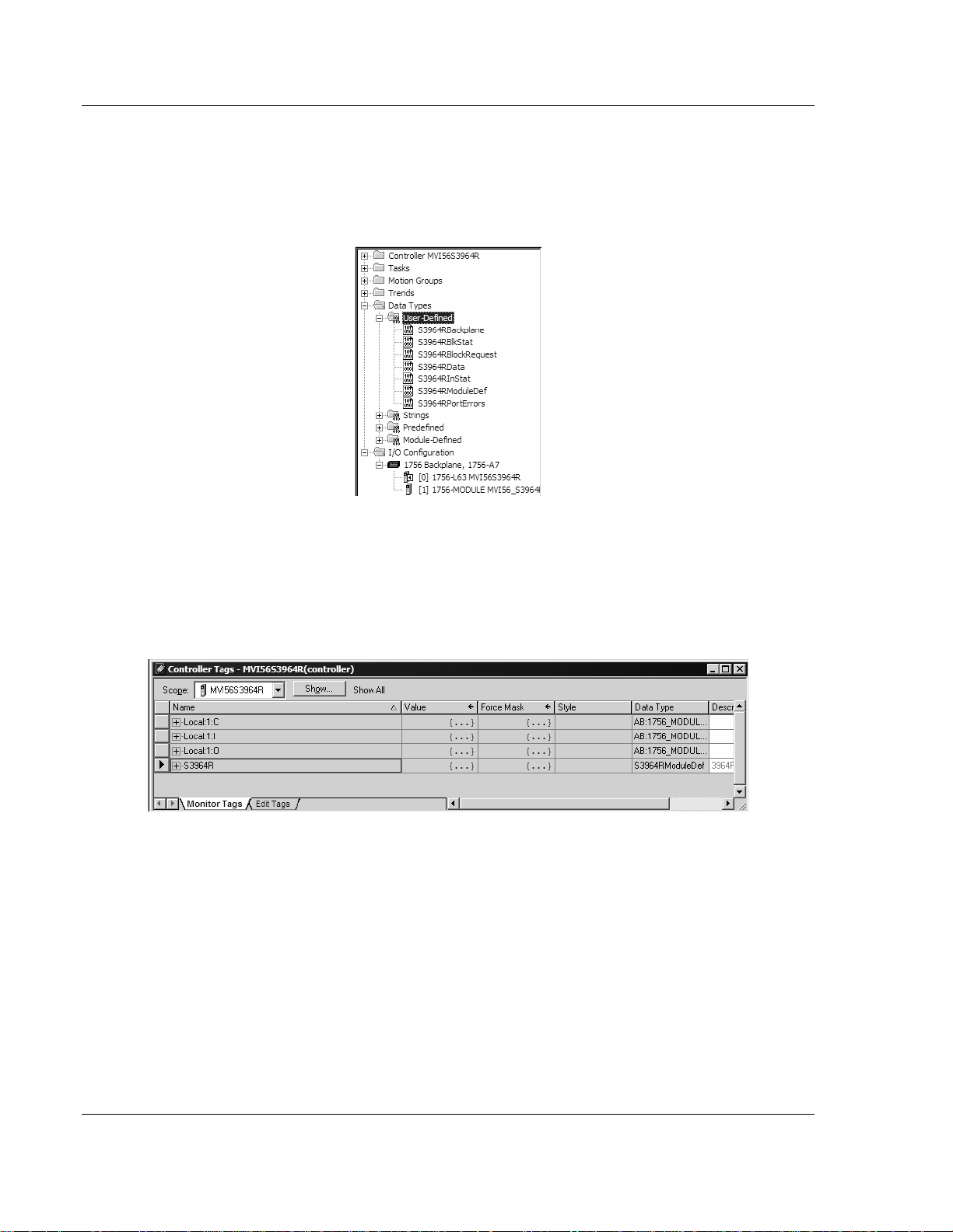
The next step in the module's setup is to define the User Defined Data Types to
be used with the module. Copy these data types from the example ladder logic if
you are not using the example. They will be defined if you are starting from the
example ladder logic. The Controller Organization window should display the
User Defined Data Types shown below:
After you have defined the User Defined Data Types, the next step is to define
the data to be used to interface with the module and the ladder logic. Open the
Controller Tags Edit Tags dialog box and enter the values shown in the following
example. The
MVI56-S3964R module is defined in the example as S3964R. You
can set the tag name to any valid tag name you desire. If you are using the
example ladder logic, this step has already been performed.
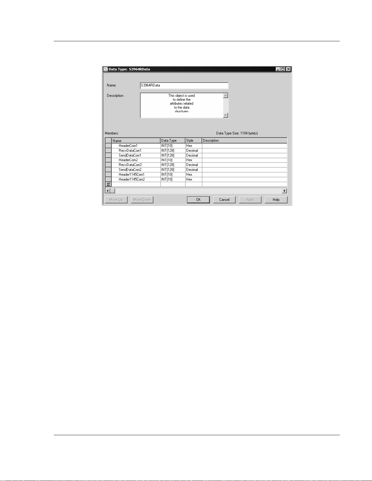
2.1.1 Module Data Object
All data related to the MVI56-S3964R module is stored in a user defined data
type. An instance of the data type is required before the module can be used.
This is done by declaring a variable of the data type in the Controller Tags Edit
Tags dialog box.
Page 22 of 78 ProSoft Technology, Inc.
April 17, 2008
Page 23
Installing and Configuring the Module MVI56-S3964RT ♦ TControlLogix PlatformT
TSiemens 3964R ProtocolT
The structure of the object is displayed in the following figure:
This object contains objects that define user and status data related to the
module. Each of these object types is discussed in the following topics of the
document.
ProSoft Technology, Inc. Page 23 of 78
April 17, 2008
Page 24
MVI56-S3964RT ♦ TControlLogix PlatformT Installing and Configuring the Module
TSiemens 3964R ProtocolT
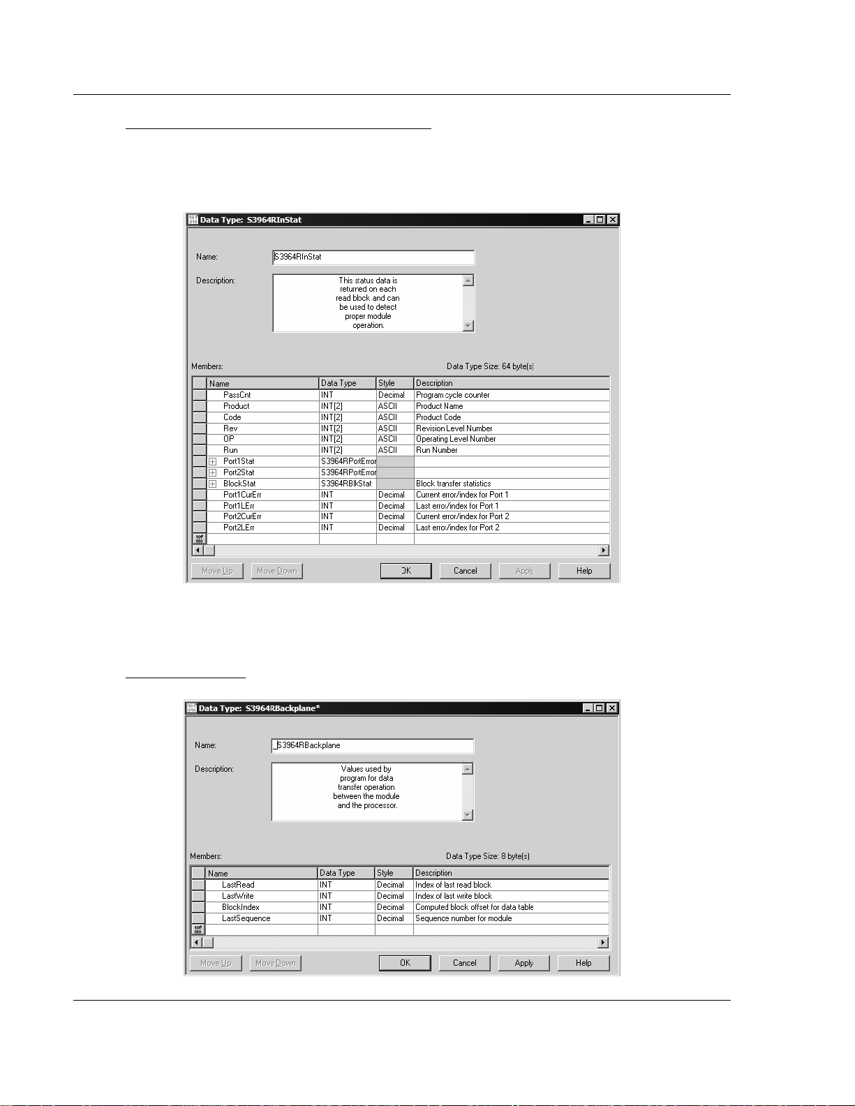
Status Object (S3964RInStat Data Structure)
This object views the status of the module. The
S3964RInstat object shown
below is updated each time a read block is received by the processor. Use this
data to monitor the state of the module at a "real-time rate".
Refer to
stored in this object.
Module Status Data Table (page 65) for a complete listing of the data
Backplane Object
Page 24 of 78 ProSoft Technology, Inc.
April 17, 2008
Page 25

Installing and Configuring the Module MVI56-S3964RT ♦ TControlLogix PlatformT
TSiemens 3964R ProtocolT
Block Control Data
This data object stores the variables required for the data transfer between the
processor and the
MVI56-S3964R module. The structure of the object is shown
in the following illustration.
Port Errors
ProSoft Technology, Inc. Page 25 of 78
April 17, 2008
Page 26

MVI56-S3964RT ♦ TControlLogix PlatformT Installing and Configuring the Module
TSiemens 3964R ProtocolT
2.2 ProSoft Configuration Builder
ProSoft Configuration Builder (PCB) provides a quick and easy way to manage
module configuration files customized to meet your application needs. PCB is not
only a powerful solution for new configuration files, but also allows you to import
information from previously installed (known working) configurations to new
projects.
2.2.1 Set Up the Project
To begin, start ProSoft Configuration Builder. If you have used other Windows
configuration tools before, you will find the screen layout familiar. ProSoft
Configuration Builder's window consists of a tree view on the left, an information
pane and a configuration pane on the right side of the window. When you first
start ProSoft Configuration Builder, the tree view consists of folders for Default
Project and Default Location, with a Default Module in the Default Location
folder. The following illustration shows the ProSoft Configuration Builder window
with a new project.
Your first task is to add the
MVI56-S3964R module to the project.
1 Use the mouse to select "Default Module" in the tree view, and then click the
right mouse button to open a shortcut menu.
Page 26 of 78 ProSoft Technology, Inc.
April 17, 2008
Page 27

Installing and Configuring the Module MVI56-S3964RT ♦ TControlLogix PlatformT
TSiemens 3964R ProtocolT
2 On the shortcut menu, choose "Choose Module Type". This action opens the
Choose Module Type dialog box.
3 In the Product Line Filter area of the dialog box, select MVI56. In the Select
Module Type dropdown list, select
MVI56-S3964R, and then click OK to save
your settings and return to the ProSoft Configuration Builder window.
The next task is to set the module parameters.
Adding a Project
To add a project to an existing project file:
1 Select the Default Project icon.
2 Choose Project from the Project menu, then choose Add Project. A new
project folder appears.
Adding a Module
To add a module to your project:
1 Double-click the Default Module icon to open the Choose Module Type dialog
box.
2 On the Choose Module Type dialog box, select the module type.
or
1 Open the Project menu and choose Location
ProSoft Technology, Inc. Page 27 of 78
April 17, 2008
Page 28

MVI56-S3964RT ♦ TControlLogix PlatformT Installing and Configuring the Module
TSiemens 3964R ProtocolT
2 On the Location menu, choose Add Module.
To add a module to a different location:
1 Right-click the Location folder and choose Add Module. A new module icon
appears.
or
Select the Location icon.
2 From the Project menu, select Location, then select Add Module.
2.2.2 Set Module Parameters
Notice that the contents of the information pane and the configuration pane
changed when you added the
MVI56-S3964R module to the project.
At this time, you may wish to rename the "Default Project" and "Default Location"
folders in the tree view.
To rename an object:
1 Select the object, and then click the right mouse button to open a shortcut
menu. From the shortcut menu, choose Rename.
2 Type the name to assign to the object.
3 Click away from the object to save the new name.
Page 28 of 78 ProSoft Technology, Inc.
April 17, 2008
Page 29

Installing and Configuring the Module MVI56-S3964RT ♦ TControlLogix PlatformT
TSiemens 3964R ProtocolT
Module Entries
To configure module parameters
1 Click on the plus sign next to the icon
to expand module
information.
2 Double-click the
icon to open the Edit dialog box.
3 To edit a parameter, select the parameter in the left pane and make your
changes in the right pane.
4 Click OK to save your changes.
Comment Entries
To add comments to your configuration file:
1 Click the plus sign to the left of the
icon to expand the Module
Comments.
2 Double-click the
icon. The Edit - Module Comment dialog
appears.
3 Enter your comment and click OK to save your changes.
Printing a Configuration File
To print a configuration file:
1 Select the Module icon, and then click the right mouse button to open a
shortcut menu.
2 On the shortcut menu, choose View Configuration. This action opens the
View Configuration window.
3 On the View Configuration window, open the File menu, and choose Print.
This action opens the Print dialog box.
ProSoft Technology, Inc. Page 29 of 78
April 17, 2008
Page 30

MVI56-S3964RT ♦ TControlLogix PlatformT Installing and Configuring the Module
TSiemens 3964R ProtocolT
4 On the Print dialog box, choose the printer to use from the dropdown list,
select printing options, and then click OK.
2.3 [Module]
This section defines the configuration for the Module level data.
2.3.1 Module Name
0 to 80 characters
This parameter assigns a name to the module that can be viewed using the
configuration/debug port. Use this parameter to identify the module and the
configuration file.
2.4 [Backplane 56]
[Backplane 56]
Status Interval: 0 #Minimum interval (ms) between status blocks (0 =
disable)
2.4.1 Block Transfer Size
60
This read-only parameter specifies the number of words in each block transferred
between the module and processor. This value is fixed at 60 words.
2.4.2 Status Interval
Minimum interval (ms) between status blocks (0 = disable)
2.5 [3964R Port x]
This section is used to define the port 1 configuration for the 3964R device
[3964R Port 1]
Enable : Yes #No=Port Disabled,Yes=Port Enabled
Baud Rate : 9600 #Baud rate for port (300, 600, 1200, 2400, 4800,
#9600, 19200, 38400, 57600, 115)
Parity : Even #N=None,O=Odd,E=Even
Data Bits : 8 #7 or 8 data bits for messages
Stop Bits : 1 #1 or 2 stop bits for messages
RTS On : 0 #Delay after RTS set before message sent (mSec)
RTS Off : 0 #Delay after message before RTS dropped (mSec)
Use CTS Line : No #Monitor CTS modem line (Y/N)
Swap : 0 #0=No Data Byte Swapping, 1=Data Byte Swapping
Priority : 1 #0=High Priority, 1=Low Priority
Protocol : 0 #0=3964 RK512, 1=3964
ACK Delay : 1000 #Number of mSec to wait for ACK (Default 1000ms)
Setup Attempts : 1 #Number of times to try to connect to CP (Default 6)
Transmit Attempts : 1 #Number of times to try to transmit to CP (Default 6)
Page 30 of 78 ProSoft Technology, Inc.
April 17, 2008
Page 31

Installing and Configuring the Module MVI56-S3964RT ♦ TControlLogix PlatformT
TSiemens 3964R ProtocolT
2.5.1 Enable
Yes or No
This parameter specifies whether to enable or disable the port. No = Port
Disabled, Yes = Port Enabled.
2.5.2 Baud Rate
300 to 115200
This parameter specifies the baud rate to be used on the port. Valid values are
300, 600, 1200, 2400, 4800, 9600, 19200, 38400, 57600, and 115200.
2.5.3 Parity
N, O, E
This parameter specifies the parity setting for this port. Valid values are N =
None, O = Odd, E = Even.
2.5.4 Data Bits
7 or 8
This parameter specifies the number of message data bits. Valid values are 7 or
8 bits.
2.5.5 Stop Bits
1 or 2
This parameter specifies the number of message stop bits. Valid values are 1 or
2 stop bits.
2.5.6 RTS On
Delay (in milliseconds) after RTS before message is sent.
2.5.7 RTS Off
Delay (in milliseconds) after message before RTS dropped.
2.5.8 Use CTS Line
Yes or No
This parameter specifies whether or not to monitor CTS modem line.
2.5.9 Swap
0 or 1
ProSoft Technology, Inc. Page 31 of 78
April 17, 2008
Page 32

MVI56-S3964RT ♦ TControlLogix PlatformT Installing and Configuring the Module
TSiemens 3964R ProtocolT
This parameter specifies whether bytes should be swapped. 0 = No data byte
swapping, 1 = Data byte swapping.
2.5.10 Priority
0 or 1
This parameter specifies whether the data is high priority or low priority. 0 = High
priority, 1 = Low Priority.
2.5.11 Protocol
0 or 1
0=3964 RK512, 1=3964
2.5.12 ACK Delay
Number of milliseconds to wait for ACK. The default is 1000 ms.
2.5.13 Setup Attempts
Number of times to try to connect to CP (Default 6)
2.5.14 Transmit Attempts
Number of times to try to transmit to CP (Default 6)
2.6 Download the Project to the Module
In order for the module to use the settings you configured, you must download
(copy) the updated Project file from your PC to the module.
To Download the Project File
1 In the tree view in ProSoft Configuration Builder, click once to select the
MVI56-S3964R module.
2 Open the
will scan your PC for a valid com port (this may take a few seconds). When
PCB has found a valid com port, the following dialog box will open.
Project menu, and then choose Module / Download. The program
Page 32 of 78 ProSoft Technology, Inc.
April 17, 2008
Page 33

Installing and Configuring the Module MVI56-S3964RT ♦ TControlLogix PlatformT
TSiemens 3964R ProtocolT
3 Choose the com port to use from the dropdown list, and then click the
Download button.
The module will perform a platform check to read and load its new settings.
When the platform check is complete, the status bar in ProSoft Configuration
Builder will be updated with the message
"Module Running".
ProSoft Technology, Inc. Page 33 of 78
April 17, 2008
Page 34

MVI56-S3964RT ♦ TControlLogix PlatformT Installing and Configuring the Module
TSiemens 3964R ProtocolT
Page 34 of 78 ProSoft Technology, Inc.
April 17, 2008
Page 35

Ladder Logic MVI56-S3964RT ♦ TControlLogix PlatformT TSiemens 3964R ProtocolT
3 Ladder Logic
In This Chapter
Introduction............................................................................................35
Commands ............................................................................................ 36
Ladder logic is required for application of the MVI56-S3964R module. Tasks that
must be handled by the ladder logic are module data transfer, special block
handling and status data receipt. Additionally, a power-up handler may be
needed to handle the initialization of the module's data and to clear any
processor fault conditions.
The sample ladder logic, on the ProSoft Solutions CD-ROM, is extensively
commented, to provide information on the purpose and function of each rung. For
most applications, the sample ladder will work without modification.
3.1 Introduction
The example programs mentioned in the following paragraphs illustrate the
principle of how to communicate between an
processor. All programs mentioned were tested with appropriate communication
partners.
It is up to the programmer to examine the programs in detail and integrate them
into the ControlLogix processor application.
The following setups/limitations are to be observed in the example
programs:
Changes according to the requirements of your ControlLogix system are
recommended for setups only. Limitations must not be changed.
Setup: The MVI56-S3964R resides in slot 2 of the ControlLogix chassis.
Setup: The 1756-L series controller resides in slot 0 of the ControlLogix
chassis.
ATTENTION: You must be trained in programming and operating Rockwell
Automation 1756-L series controllers and ControlLogix environment. Otherwise,
incorrect use may lead to personal injury or death, property damages or
economic loss.
MVI56-S3964R and a ControlLogix
3.1.1 Explanations About the Example Programs
is the general S3964R communication program used for the following types of
3964R jobs:
ProSoft Technology, Inc. Page 35 of 78
April 17, 2008
Page 36

MVI56-S3964RT ♦ TControlLogix PlatformT Ladder Logic
TSiemens 3964R ProtocolT
3.1.2 The 3964R Communication Program
The general functionality of the program is as follows:
Send jobs to a CP:
Transfer the job data to the MVI56-S3964R.
Acknowledgement from the
Depending on the type of send job the transfer of the user data from/to the
MVI56-S3964R/ControlLogix processor takes place.
Acknowledgement from the
successful/unsuccessful completion of the send job.
Receive jobs from a CP:
Depending on the type of receive job the transfer of the user data from/to the
MVI56-S3964R/ControlLogix processor takes place. The header data
generated from the
S3964R
needs no extra job data from the ControlLogix processor for receive
MVI56-S3964R will be added automatically. The MVI56-
jobs, it will be triggered through the STX character sent from the CP to
establish the communication.
Acknowledgement from the
successful/unsuccessful completion of the receive job.
MVI56-S3964R regarding validity of the job data.
MVI56-S3964R regarding
MVI56-S3964R regarding
During the processes described above additional status/error messages may be
transferred from the
Module Status Data Table (page 65)). Refer to Error Processing for more
information.
3.2 Commands
The WriteData sub-routine is used to handle special block processing, as well as
3964R communication jobs.
Special blocks include:
9998 - Warm Boot
9999 - Cold Boot
3.2.1 9998 Warm Boot
The ControlLogix processor can request a warm boot operation of the module by
placing a value of 9998 in Word 0 of the module's Output Image.
3.2.2 9999 Cold Boot
The ControlLogix processor can request a cold boot operation by the module by
placing a value of 9999 in Word 0 of the module's Output Image.
MVI56-S3964R to the ControlLogix processor (refer to
Page 36 of 78 ProSoft Technology, Inc.
April 17, 2008
Page 37

Diagnostics and Troubleshooting MVI56-S3964RT ♦ TControlLogix PlatformT TSiemens 3964R ProtocolT
4 Diagnostics and Troubleshooting
In This Chapter
Reading Status Data from the Module .................................................. 37
LED Status Indicators............................................................................ 47
The module provides information on diagnostics and troubleshooting in the
following forms:
Status data values are transferred from the module to the processor.
Data contained in the module can be viewed through the
Configuration/Debug port attached to a terminal emulator.
LED status indicators on the front of the module provide information on the
module's status.
4.1 Reading Status Data from the Module
The MVI56-3964R module returns a 31-word Status Data Block (page 65) that
may be used to determine the module's operating status.
This data is transferred to the ControlLogix processor every time the module
does not have 3964R communication data to send to the processor.
The Configuration/Debug port provides the following functionality:
Full view of the module's configuration data
View of the module's status data
Version Information
Control over the module (warm boot, cold boot, transfer configuration)
4.1.1 Required Hardware
You can connect directly from your computer's serial port to the serial port on the
module to view configuration information, perform maintenance, and send
(upload) or receive (download) configuration files.
ProSoft Technology recommends the following minimum hardware to connect
your computer to the module:
80486 based processor (Pentium preferred)
1 megabyte of memory
At least one UART hardware-based serial communications port available.
USB-based virtual UART systems (USB to serial port adapters) often do not
function reliably, especially during binary file transfers, such as when
uploading/downloading configuration files or module firmware upgrades.
A null modem serial cable.
ProSoft Technology, Inc. Page 37 of 78
April 17, 2008
Page 38

MVI56-S3964RT ♦ TControlLogix PlatformT Diagnostics and Troubleshooting
TSiemens 3964R ProtocolT
4.1.2 The Configuration/Debug Menu
The Configuration and Debug menu for this module is arranged as a tree
structure, with the Main Menu at the top of the tree, and one or more sub-menus
for each menu command. The first menu you see when you connect to the
module is the Main menu.
Because this is a text-based menu system, you enter commands by typing the
command letter from your computer keyboard in the diagnostic window in
ProSoft Configuration Builder (PCB). The module does not respond to mouse
movements or clicks. The command executes as soon as you press the
command letter — you do not need to press
letter, a new screen will be displayed in your terminal application.
Using the Diagnostic Window in ProSoft Configuration Builder
To connect to the module's Configuration/Debug serial port:
1 Start PCB program with the application file to be tested. Right click over the
module icon.
[Enter]. When you type a command
2 On the shortcut menu, choose Diagnostics.
Page 38 of 78 ProSoft Technology, Inc.
April 17, 2008
Page 39

Diagnostics and Troubleshooting MVI56-S3964RT ♦ TControlLogix PlatformT
TSiemens 3964R ProtocolT
3 This action opens the Diagnostics dialog box. Press "?" to display the Main
Menu.
Important: The illustrations of configuration/debug menus in this section are intended as a general
guide, and may not exactly match the configuration/debug menus in your own module.
If there is no response from the module, follow these steps:
1 Verify that the null modem cable is connected properly between your
computer's serial port and the module. A regular serial cable will not work.
2 On computers with more than one serial port, verify that your communication
program is connected to the same port that is connected to the module.
If you are still not able to establish a connection, contact ProSoft Technology for
assistance.
Navigation
All of the sub-menus for this module contain commands to redisplay the menu or
return to the previous menu. You can always return from a sub-menu to the next
higher menu by pressing
[M] on your keyboard.
ProSoft Technology, Inc. Page 39 of 78
April 17, 2008
Page 40

MVI56-S3964RT ♦ TControlLogix PlatformT Diagnostics and Troubleshooting
TSiemens 3964R ProtocolT
The organization of the menu structure is represented in simplified form in the
following illustration:
The remainder of this section shows you the menus available for this module,
and briefly discusses the commands available to you.
Keystrokes
The keyboard commands on these menus are almost always non-case sensitive.
You can enter most commands in lower case or capital letters.
The menus use a few special characters (
exactly as shown. Some of these characters will require you to use the
[?], [-], [+], [@]) that must be entered
[Shift],
[Ctrl] or [Alt] keys to enter them correctly. For example, on US English
keyboards, enter the
Also, take care to distinguish capital letter
number
[1]; likewise for capital letter [O] and number [0]. Although these
[?] command as [Shift][/].
[I] from lower case letter [l] (L) and
characters look nearly the same on the screen, they perform different actions on
the module.
4.1.3 Main Menu
When you first connect to the module from your computer, your terminal screen
will be blank. To activate the main menu, press the
keyboard. If the module is connected properly, the following menu will appear on
your terminal screen:
[?] key on your computer's
Page 40 of 78 ProSoft Technology, Inc.
April 17, 2008
Page 41

Diagnostics and Troubleshooting MVI56-S3964RT ♦ TControlLogix PlatformT
TSiemens 3964R ProtocolT
Caution: Some of the commands available to you from this menu are designed for advanced
debugging and system testing only, and can cause the module to stop communicating with the
processor or with other devices, resulting in potential data loss or other failures. Only use these
commands if you are specifically directed to do so by ProSoft Technology Technical Support staff.
Some of these command keys are not listed on the menu, b ut are active nevertheless. Please be
careful when pressing keys so that you do not accidentally execute an unwanted command.
Redisplaying the Menu
Press
at a screen of data, and want to view the menu choices available to you.
[?] to display the current menu. Use this command when you are looking
Viewing Version Information
Press
[V] to view Version information for the module.
Use this command to view the current version of the software for the module, as
well as other important values. You may be asked to provide this information
when calling for technical support on the product.
Values at the bottom of the display are important in determining module
operation. The Program Scan Counter value is incremented each time a
module's program cycle is complete.
Tip: Repeat this command at one-second intervals to determine the frequency of program
execution.
Opening the Database Menu
Press
current contents of the module's database.
[D] to open the Database View menu. Use this menu command to view the
Clearing Diagnostic Data
Press
[C] to clear diagnostic data from the module's memory.
Opening the Backplane Menu
Press
[B] from the Main Menu to view the Backplane Data Exchange List. Use
this command to display the configuration and statistics of the backplane data
transfer operations.
Tip: Repeat this command at one-second intervals to determine the number of blocks transferred
each second.
Opening the Protocol_Serial_S3964R Menu
Press
[0] or [1] from the Main Menu to open the Protocol_Serial_S3964R menu
for S3964R Ports 1 and 2.
ProSoft Technology, Inc. Page 41 of 78
April 17, 2008
Page 42

MVI56-S3964RT ♦ TControlLogix PlatformT Diagnostics and Troubleshooting
TSiemens 3964R ProtocolT
Use this command to view communication status and statistics for the selected
port. This information can be useful for trouble-shooting communication
problems.
Transferring the Configuration File from MVI56 module to PC
Press
[S] to receive (download) the configuration file from the module to your
PC.
Press
[Y] to confirm the file transfer, and then follow the instructions on the
terminal screen to complete the file transfer process.
After the file has been successfully downloaded, you can open and edit the file to
change the module's configuration.
Transferring the Configuration File from PC to MVI56 module
Press
[R] to send (upload) the configuration file from your PC to the module and
store the file on the module's Compact Flash Disk.
Press
[Y] to confirm the file transfer, and then follow the instructions on the
terminal screen to complete the file transfer process.
After the file has been successfully downloaded, the module will restart the
program and load the new configuration information. Review the new
configuration using menu commands
configured correctly.
[0] and [1] to verify that the module is
Warm Booting the Module
Caution: Some of the commands available to you from this menu are designed for advanced
debugging and system testing only, and can cause the module to stop communicating with the
processor or with other devices, resulting in potential data loss or other failures. Only use these
commands if you are specifically directed to do so by ProSoft Technology Technical Support staff.
Some of these command keys are not listed on the menu, b ut are active nevertheless. Please be
careful when pressing keys so that you do not accidentally execute an unwanted command.
Press [W] from the Main Menu to warm boot (restart) the module. This command
will cause the program to exit and reload, refreshing configuration parameters
that must be set on program initialization. Only use this command if you must
force the module to re-boot.
Exiting the Program
Caution: Some of the commands available to you from this menu are designed for advanced
debugging and system testing only, and can cause the module to stop communicating with the
processor or with other devices, resulting in potential data loss or other failures. Only use these
commands if you are specifically directed to do so by ProSoft Technology Technical Support staff.
Some of these command keys are not listed on the menu, b ut are active nevertheless. Please be
careful when pressing keys so that you do not accidentally execute an unwanted command.
Page 42 of 78 ProSoft Technology, Inc.
April 17, 2008
Page 43

Diagnostics and Troubleshooting MVI56-S3964RT ♦ TControlLogix PlatformT
TSiemens 3964R ProtocolT
Press
[Esc] to restart the module and force all drivers to be loaded. The module
will use the configuration stored in the module's Flash ROM to configure the
module.
4.1.4 Database View Menu
Press [D] from the Main Menu to open the Database View menu. Use this menu
command to view the current contents of the module's database. Press
view a list of commands available on this menu.
M = Main Menu
D = Database Menu
? = Display Menu Redisplays (refreshes) this menu
0 – 3 = Pages 0 to 3000
S = Show Again Redisplays last selected page of data
– = Back 5 Pages
P = Previous Page
+ = Skip 5 Pages
N = Next Page
D = Decimal Display
H = Hexadecimal Display
F = Float Display
A = ASCII Display
M = Main Menu Goes up one level to main menu
Selects page 0, 1000, 2000 or 3000
Goes back five pages of data
Goes back one page of data
Goes forward five pages of data
Goes forward one page of data
Displays data in decimal format
Displays data in hex format
Displays data in floating point format
Displays data in text format
[?] to
Viewing Register Pages
To view sets of register pages, use the keys described below:
Command Description
[0]
[1]
[2]
Display registers 0 to 99
Display registers 1000 to 1099
Display registers 2000 to 2099
And so on. The total number of register pages available to view depends on your
module's configuration.
Displaying the Current Page of Registers Again
ProSoft Technology, Inc. Page 43 of 78
April 17, 2008
Page 44

MVI56-S3964RT ♦ TControlLogix PlatformT Diagnostics and Troubleshooting
TSiemens 3964R ProtocolT
This screen displays the current page of 100 registers in the database.
Moving Back Through 5 Pages of Registers
Press
registers of data.
[-] from the Database View menu to skip back to the previous 500
Viewing the Previous 100 Registers of Data
Press
data.
[P] from the Database View menu to display the previous 100 registers of
Skipping 500 Registers of Data
Hold down
[Shift] and press [=] to skip forward to the next 500 registers of data.
Viewing the Next 100 Registers of Data
Press
registers of data.
[N] from the Database View menu to select and display the next 100
Viewing Data in Decimal Format
Press
[D] to display the data on the current page in decimal format.
Viewing Data in Hexadecimal Format
Press
[H] to display the data on the current page in hexadecimal format.
Viewing Data in Floating Point Format
Press
[F] from the Database View menu. Use this command to display the data
on the current page in floating point format. The program assumes that the
values are aligned on even register boundaries. If floating-point values are not
aligned as such, they are not displayed properly.
Viewing Data in ASCII (Text) Format
Press
for regions of the database that contain ASCII data.
[A] to display the data on the current page in ASCII format. This is useful
Returning to the Main Menu
Press
[M] to return to the Main Menu.
Page 44 of 78 ProSoft Technology, Inc.
April 17, 2008
Page 45

Diagnostics and Troubleshooting MVI56-S3964RT ♦ TControlLogix PlatformT
TSiemens 3964R ProtocolT
4.1.5 Backplane Menu
Press [B] from the Main Menu to view the Backplane Data Exchange List. Use
this command to display the configuration and statistics of the backplane data
transfer operations. Press
M = Main Menu
Redisplaying the Menu
[?] to view a list of commands available on this menu.
B = Backplane Menu
? = Display Menu
V = Version Information
M = Main Menu
C = Configuration Information
D = Diagnostic Information
Redisplays (refreshes) this menu
Displays version information screen
Goes up one level to main menu
Displays configuration screen
Displays backplane diagnostic
information
Press
at a screen of data, and want to view the menu choices available to you.
[?] to display the current menu. Use this command when you are looking
Viewing Version Information
Press
[V] to view Version information for the module.
Use this command to view the current version of the software for the module, as
well as other important values. You may be asked to provide this information
when calling for technical support on the product.
Values at the bottom of the display are important in determining module
operation. The Program Scan Counter value is incremented each time a
module's program cycle is complete.
Tip: Repeat this command at one-second intervals to determine the frequency of program
execution.
Returning to the Main Menu
Press
[M] to return to the Main Menu.
Viewing Configuration Information
Press
or device.
[C] to view configuration information for the selected port, protocol, driver
Viewing Backplane Diagnostic Information
Press
[D] to view Backplane Diagnostic information.
ProSoft Technology, Inc. Page 45 of 78
April 17, 2008
Page 46

MVI56-S3964RT ♦ TControlLogix PlatformT Diagnostics and Troubleshooting
TSiemens 3964R ProtocolT
Use this command to display the configuration and statistics of the backplane
data transfer operations between the module and the processor. The information
on this screen can help determine if there are communication problems between
the processor and the module.
Tip: Repeat this command at one-second intervals to determine the number of blocks transferred
each second
4.1.6 Protocol Serial 3964R Menu
Press [0] or [1] to view protocol serial information for ports 1 and 2, respectively.
Use this command to view a variety of error and status screens for the port.
Press
[?] to view a list of commands available on this menu.
M = Main Menu
0 / 1 = Protocol_Serial Menu
? = Display Menu Redisplays (refreshes) this menu
V = Version Information
M = Main Menu Goes up one level to main menu
C = Configuration Information
S = Serial Port
E = Error/Status Information
Displays version information screen
Displays configuration information
screen
Opens the Serial Port menu
Opens the Command List menu
See Serial Port Menu section
See Command List Menu section
Redisplaying the Menu
Press
at a screen of data, and want to view the menu choices available to you.
[?] to display the current menu. Use this command when you are looking
Viewing Version Information
Press
[V] to view Version information for the module.
Use this command to view the current version of the software for the module, as
well as other important values. You may be asked to provide this information
when calling for technical support on the product.
Values at the bottom of the display are important in determining module
operation. The Program Scan Counter value is incremented each time a
module's program cycle is complete.
Tip: Repeat this command at one-second intervals to determine the frequency of program
execution.
Returning to the Main Menu
Press
[M] to return to the Main Menu.
Page 46 of 78 ProSoft Technology, Inc.
April 17, 2008
Page 47

Diagnostics and Troubleshooting MVI56-S3964RT ♦ TControlLogix PlatformT
TSiemens 3964R ProtocolT
Viewing Configuration Information
Press
or device.
[C] to view configuration information for the selected port, protocol, driver
Opening the Serial Port Menu
Press
additional serial port driver settings.
[S] to open the Serial Port menu. Use this command to view and change
Viewing Error and Status Data
Press
[E] to display the error/status data for the module.
4.2 LED Status Indicators
The LEDs indicate the module's operating status as follows:
ProSoft
Module
CFG Green
BP ACT Amber
OK Red/
Color Status Indication
On
Off
On Data being transferred between master and port 1. P1 Green
Off No data
On Data being transferred between master and port 2. P2 Green
Off No data
Off The MVI56-3964R is working normally. APP Status Amber
On
On
Off
Off
Green
Green The module is operating normally.
Red
Off The battery voltage is OK and functioning. BAT Red
On
Data is being transferred between the module and a
remote terminal using the Configuration/Debug port.
No data is being transferred on the Configuration/Debug
port.
The MVI56-3964R module program has recognized a
communication error.
The LED is on when the module is performing a write
operation on the backplane.
The LED is off when the module is performing a read
operation on the backplane. Under normal operation, the
LED should blink rapidly on and off.
The card is not receiving any power and is not securely
plugged into the rack.
The program has detected an error or is being configured.
If the LED remains red for over 10 seconds, the program
has probably halted. Remove the card from the rack and
re-insert the card to restart the module's program.
The battery voltage is low or battery is not present. Allow
battery to charge by keeping module plugged into rack for
24 hours. If BAT LED still does not go off, contact ProSoft
Technology, as this is not a user serviceable item.
If the APP, BP ACT and OK LEDs blink at a rate of every one-second, this
indicates a serious problem with the module. Call ProSoft Technology support to
arrange for repairs.
ProSoft Technology, Inc. Page 47 of 78
April 17, 2008
Page 48

MVI56-S3964RT ♦ TControlLogix PlatformT Diagnostics and Troubleshooting
TSiemens 3964R ProtocolT
4.2.1 Clearing a Fault Condition
Typically, if the OK LED on the front of the module turns red for more than ten
seconds, a hardware problem has been detected in the module, or the program
has exited.
To clear the condition, follow these steps:
1 Turn off power to the rack
2 Remove the card from the rack
3 Verify that all jumpers are set correctly
4 If the module requires a Compact Flash card, verify that the card is installed
correctly
5 Re-insert the card in the rack and turn the power back on
6 Verify the configuration data being transferred to the module from the
ControlLogix processor.
If the module's OK LED does not turn green, verify that the module is inserted
completely into the rack. If this does not cure the problem, contact ProSoft
Technology Support.
4.2.2 Troubleshooting
Use the following troubleshooting steps if you encounter problems when the
module is powered up. If these steps do not resolve your problem, please contact
ProSoft Technology Technical Support.
Processor Errors
Problem Description Steps to take
Processor Fault
Processor I/O LED
flashes
Verify that the module is plugged into the slot that has been configured
for the module.
Verify that the slot in the rack configuration has been set up correctly in
the ladder logic.
This indicates a problem with backplane communications. Verify that all
modules in the rack are configured in the ladder logic.
Page 48 of 78 ProSoft Technology, Inc.
April 17, 2008
Page 49

Diagnostics and Troubleshooting MVI56-S3964RT ♦ TControlLogix PlatformT
TSiemens 3964R ProtocolT
Module Errors
Problem Description Steps to take
BP ACT LED remains
off or blinks slowly
OK LED remains red
This indicates that backplane transfer operations are failing. Connect to
the module's Configuration/Debug port to check this.
To establish backplane communications, verify the following items:
The processor is in Run mode.
The backplane driver is loaded in the module.
The module is configured for read and write block data transfer.
The ladder logic handles all read and write block situations.
The module is configured in the processor.
The program has halted or a critical error has occurred. Connect to the
Configuration/Debug port to see if the module is running. If the program
has halted, turn off power to the rack, remove the card from the rack
and re-insert the card in the rack, and then restore power to the rack.
ProSoft Technology, Inc. Page 49 of 78
April 17, 2008
Page 50

MVI56-S3964RT ♦ TControlLogix PlatformT Diagnostics and Troubleshooting
TSiemens 3964R ProtocolT
Page 50 of 78 ProSoft Technology, Inc.
April 17, 2008
Page 51

Reference MVI56-S3964RT ♦ TControlLogix PlatformT
TSiemens 3964R ProtocolT
5 Reference
In This Chapter
Product Specifications ........................................................................... 51
Functional Overview.............................................................................. 53
Cable Connections ................................................................................ 61
Reference Documents...........................................................................65
Status Data............................................................................................ 65
Error Codes ........................................................................................... 66
5.1 Product Specifications
The MVI56 S3964R Protocol module from ProSoft Technology allows point-topoint communication between a ControlLogix processor (1756-L1, -L1Mx, L55,
L6x) and a partner with 3964R communication capability.
5.1.1 Features and Benefits
The 3964R protocol (with or without RK512) was designed by Siemens for bidirectional data communication through a point-to-point connection. It is a peer to
peer protocol with read and write access. A BCC checksum ensures the safety of
the transfer.
5.1.2 General Specifications
Single Slot - 1756 backplane compatible
Local or remote rack
The module is recognized as an Input/Output module and has access to
processor memory for data transfer between processor and module
Ladder Logic is used for data transfer between module and processor.
Configuration data obtained through user-defined ladder. Sample ladder file
included
ProSoft Technology, Inc. Page 51 of 78
April 17, 2008
Page 52

MVI56-S3964RT ♦ TControlLogix PlatformT Reference
TSiemens 3964R ProtocolT
5.1.3 Hardware Specifications
Specification Description
Backplane Current Load
Operating Temperature 0 to 60°C (32 to 140°F)
Storage Temperature -40 to 85°C (-40 to 185°F)
Shock 30g Operational
Relative Humidity 5% to 95% (non-condensing)
LED Indicators Module Status
Debug/Configuration port (CFG)
CFG Port (CFG) RJ45 (DB-9M with supplied cable)
Application ports (PRT1 & PRT2)
Full hardware handshaking control, providing radio, modem and multi-drop support
Software configurable
communication parameters
App Ports (P1,P2) (Serial modules) RJ45 (DB-9M with supplied cable)
Shipped with Unit RJ45 to DB-9M cables for each port
800 mA @ 5 V DC
3mA @ 24V DC
50g non-operational
Vibration: 5 g from 10 to 150 Hz
Backplane Transfer Status
Application Status
Serial Activity
RS-232 only
Baud rate: 110 to 115,200 baud, depending on protocol
RS-232 and 422
Parity: none, odd or even
Data bits: 5, 6, 7, or 8
Stop bits: 1 or 2
RTS on/off delay: 0 to 65535 milliseconds
RS-232 handshaking configurable
500V Optical isolation from backplane
6-foot RS-232 configuration cable
5.1.4 Functional Specifications
Single-slot, ControlLogix backplane compatible
Multiple modules can be placed in a rack up to the chassis power supply limit
While in 3964R with RK512 mode on PRT1 and PRT2, DB-SEND and DB-
FETCH instructions can be initiated from the ControlLogix processor or
received by the communications partner
While in 3964R without RK512 mode on PRT1 and PRT2, data can be sent
from the ControlLogix processor or be received from the communications
partner
The maximum transfer size is 512 bytes in any mode
Data byte swapping can be configured to adjust to a different word format
Page 52 of 78 ProSoft Technology, Inc.
April 17, 2008
Page 53

Reference MVI56-S3964RT ♦ TControlLogix PlatformT
TSiemens 3964R ProtocolT
While in 3964R with RK512 mode on PRT1 and PRT2, evaluation of the
header information DB (data block), DW (data word) and coordination bytes 9
and 10 is possible
Communication activity and diagnostics are available through LEDs and
acknowledgment telegrams
Ladder Logic
Ladder logic programming in the ControlLogix processor is required in order to
enable and support the Siemens 3964R protocol functionality. The ladder
program handles the encoding/decoding of data transferred from the module as
well as the initiation of protocol-specific functionality in the module. Example
ladder programs are provided with the module to simplify the implementation of
the module in the user application.
5.2 Functional Overview
5.2.1 Products in the Environment
The 3964R protocol can be installed in all local ControlLogix chassis with at least
one controller.
You can obtain more information about ControlLogix and the ControlLogix
environment through your Rockwell Automation branch office.
Product Compatibility
The communication between the MVI56 and the ControlLogix processor is
realized through the module's Input/Output Images.
5.2.2 3964R Protocol Overview
The 3964R Protocol in General
The 3964R protocol defined by Siemens is used for bi-directional data exchange
between two peers through a bit-serial point-to-point connection. This protocol
may be additionally embedded in the RK512 telegram level. If 3964R is used with
RK512, each participant can send jobs to its partner and has read
and write access
(DB-SEND) to the partner's data. The data exchange is realized
in the form of messages and response messages. The maximum user data
volume is 512 byte per job and 128 byte per message.
3964R without RK512 allows only block wise sending and receiving of data. The
detailed handshake procedure through messages and response messages is not
applicable in this case.
(DB-FETCH)
ProSoft Technology, Inc. Page 53 of 78
April 17, 2008
Page 54

MVI56-S3964RT ♦ TControlLogix PlatformT Reference
TSiemens 3964R ProtocolT
If both partners want to send a job (3964R with RK512) or data (3964R without
RK512) at the same time, the resulting initialization conflict will be solved through
the high/low priority setup. In such a case one partner will be allocated high
priority and the other one low priority. Thus, in case of an initialization conflict the
device with low priority will defer its job whereas the device with the high priority
will be able to send a job.
The safety of data transmission on the line is guaranteed by a
BCC checksum.
You should have sufficient knowledge about the 3964R protocol in order to
understand the operation of the driver for the
efficient use of the example programs.
MVI56-S3964R and to make
MVI56-S3964R Operation
The protocol realized on the
MVI56-S3964R has the following special features:
Immediately after power-up and completion of the internal/external
initialization procedures the
MVI56-S3964R with installed 3964R protocol is
ready to serve as an interface between a ControlLogix processor and one or
two communication partners using 3964R protocol. The parameterization of
the module is realized through a configuration file. This is where a
differentiation between the communication modes 3964R with RK512 and
3964R without RK512 takes place.
The communication mode 3964R without RK512 supports processing of up to
512 bytes.
The serial transmission parameters are optional and can be allocated
independently to each interface. Possible baud rates are 300 to 115200
following parity setups are possible:
Even, Odd and None.
. The
5.2.3 General Concepts
Module Power Up
On power up the module begins performing the following logical functions:
Initialize hardware components
o
Initialize ControlLogix backplane driver
o
Test and Clear all RAM
o
Initialize the serial communication ports
Read module configuration from the Compact Flash
Initialize Module Register space
Set up the communication interface for the debug/configuration port
When this initialization procedure is complete, the module will begin
communicating with other nodes on the network, depending on the configuration.
Page 54 of 78 ProSoft Technology, Inc.
April 17, 2008
Page 55

Reference MVI56-S3964RT ♦ TControlLogix PlatformT
TSiemens 3964R ProtocolT
Main Logic Loop
Upon completing the power up configuration process, the module enters an
infinite loop that performs the functions shown in the following diagram.
From Power Up Logic
Call I/O Handler
Call CFG/DEBUG Port
Driver
Call Network
Slave Drivers
Backplane Data Transfer
Receive from CP
Transfers data between the module and processor
Call I/O Handler
(user, status, etc.)
Call S erial Port Driver
Rx and Tx buffer routines are interrupt driven. Call to
serial port routines check to see if there is any data
in the buffer, and depending on the value, will either
service the buffer or wait for more characters.
Call N etwork Slave Drivers
Respond to messages received.
ProSoft Technology, Inc. Page 55 of 78
April 17, 2008
Page 56

MVI56-S3964RT ♦ TControlLogix PlatformT Reference
TSiemens 3964R ProtocolT
Send to CP
Request from CP
Block ID for the transfer of data from the processor to the module to be sent out the serial
port
9 X X X
9 Always 9 0 Not Last Block 1 Block 1 1 Port 1
9 Last block 2 Block 2 2 Port 2
3 Block 3
4 Block 4
5 Block 5
9011 First block for port 1
9921 Second and last block for port 1
9912 First and last block for port 2
Page 56 of 78 ProSoft Technology, Inc.
April 17, 2008
Page 57

Reference MVI56-S3964RT ♦ TControlLogix PlatformT
TSiemens 3964R ProtocolT
Send Block for Module to send to CP (Block 1)
Offset Data Length
0 9X1X 1
1 Header 10
11 Data 50
Send Block for Module to send to CP (Blocks 2 to 4)
Offset Data Length
0 9X2X, 9X3X, 9X4X 1
1 Data 60
Request for data Block from Module to respond to CP
Offset Data Length
0 910X 1
1 Reserved 2
3 1145h 1
4 Data Block (DB) 1
5 Data Word (DW) 1
6 Number of Data Words 1
7 Coordination Bytes 1
8 Data Type (4Dh/44h) 1
9 to 12 Reserved 4
Receive Data from CP (First Block)
Offset Data Length
0 910X 1
1 Reserved 1
2 Data Block 1 1
3 1141h/11FFh 1
4 Data Block (DB) 1
5 Data Word (DW) 1
6 Number of Data Words 1
7 Coordination Bytes 1
8 Data Type (4Dh/44h) 1
9 to 12 Reserved 4
13 Data 49
Receive Data from CP (Blocks 2 to 4)
Offset Data Length
0 910X 1
1 Reserved 1
2 Data Block (2 to 4) 1
3 Data 59
ProSoft Technology, Inc. Page 57 of 78
April 17, 2008
Page 58

MVI56-S3964RT ♦ TControlLogix PlatformT Reference
TSiemens 3964R ProtocolT
Receive Data from CP (Block 5)
Offset Data Length
0 910X 1
1 Reserved 1
2 Data Block (5) 1
3 Data 30
5.2.4 Communications
Job Allocation by the ControlLogix Controller
This section describes the different types of jobs and the relevant parameters to
be entered. For a better understanding a printout of the sample ladder file is
recommended.
Every job that is transferred to or from the
MVI56-S3964R consists of defined
header data and user data.
The Job structure in general:
Word: High Byte: Low Byte:
0 Header data
.. ..
9 Header data
10 User data
.. ..
137 User data
Header Data
The header data consists of 10 words with a job identifier and parameter data.
The header data is to be entered either in the file
or the file
HEADER_P2 to send to port 2.
HEADER_P1 to send to port 1
The header in general:
Word: High Byte: Low Byte:
0 Job identifier (hex)
1 00 Data Block (DB)
2 00 Data Word (DW)
3 Number of data words/data bytes
4 Coordination byte 9 Coordination byte 10
5 00 Data Type
6 00 00
7 00 00
8 00 00
9 00 00
The meaning of the entries and possible values are described below.
Page 58 of 78 ProSoft Technology, Inc.
April 17, 2008
Page 59

Reference MVI56-S3964RT ♦ TControlLogix PlatformT
TSiemens 3964R ProtocolT
Job Identifier
The job identifiers are defined as follows:
Send jobs to a CP:
Job: Identifier:
3964R with RK512: DB-SEND to CP 0041hex
3964R with RK512: DB-FETCH to CP 0045hex
The MVI56-S3964R receives jobs from a CP automatically without extra
parameterization. To differentiate the header data the
header to the user data received and transfers it to the ControlLogix processor.
Receive jobs from a CP
Job: Identifier:
3964R with RK512: DB-SEND from CP 1141hex
3964R with RK512: DB-FETCH from CP 1145hex
MVI56-S3964R adds a
Data Block (DB)
Number of the data block. This data block must exist in the communication
partner (3964R with RK512 only, otherwise to be set to "0").
Data Word (DW)
Number of the data word in the selected data block. The selected data block
must contain this number (3964R with RK512 only, otherwise to be set to "0").
Number of Data Words/Data Bytes
Dependent on the type of communication mode used on port 1/2 of the module,
this value will be interpreted as number of data words. This value defines
whether a job will be carried out with or without subsequent telegram. For jobs
without subsequent telegram the value will be 1 ... 64 words (1 … 128 bytes),
and for jobs with subsequent telegram(s) it will be 65 ... 256 words (129 … 512
bytes).
Coordination Byte 9/10
3964R with RK512 send jobs offer the possibility of entering so called
coordination bytes (byte 9 and 10 in the RK512 telegram header). Otherwise to
be set to "0".
Data Type
The send message can request a data type of Data Words (44h) or Marker
(4Dh). If the value is 0 (zero), then data words is used.
Receive Jobs
To receive jobs from a CP only, no additional parameterization is necessary. The
user data received is stored in a file in the ControlLogix processor.
The following table shows an example of the data
stored in HeaderCom1 in case
of a DB-Send from a CP. The CP is connected to port 1.
ProSoft Technology, Inc. Page 59 of 78
April 17, 2008
Page 60

MVI56-S3964RT ♦ TControlLogix PlatformT Reference
TSiemens 3964R ProtocolT
Word: High Byte: Low Byte:
0 1141hex
1 00 Data Block (DB)
2 00 Data Word (DW)
3 Number of data words (total number)
4 Number of data words (actual block)
5 00 00
6 00 00
7 00 00
8 00 00
9 00 00
1
= This is the total number of data words for the whole job.
2
= This is the number of data words stored in RecvDataCom1.
1
2
The user data is copied to
RecvDataCom1. This is the file you should operate
with.
For port 2, which is similar to port 1, the file for storing the user data received is
called
RecvDataCom2.
Send Jobs
To send a job to a CP, the next step is to define the appropriate header for the
job. The following table shows an example of the header data for a DB-Send job
to a CP with the following parameters:
DB = 10, DW = 0, 128 words, coordination byte 9 = FFhex, coordination byte 10
= FFhex, Data Type = 44hex.
Word: High Byte: Low Byte:
0 0041hex
1 00 10
2 00 0
3 80hex (= 128dec)
4 FFhex FFhex
5 00 44hex
6 00 00
7 00 00
8 00 00
9 00 00
A DB-Fetch job will be parameterized similar to the example above.
To send with 3964R without RK512 to a CP (identifier 00FFhex), the values for
DB, DW and the coordination bytes will be ignored and can be set to "0".
The next step is to copy the user data into the appropriate files of the
ControlLogix processor.
Page 60 of 78 ProSoft Technology, Inc.
April 17, 2008
Page 61

Reference TMVI56-S3964RTT ♦ TControlLogix PlatformT
TSiemens 3964R ProtocolT
5.2.5 Job Processing
Both ports can be used independently from each other (multi tasking).
A possible initialization conflict will be solved as follows:
MVI56-S3964R has "High Priority":
The MVI56-S3964R retries the sending of the 3964R start character (STX) 3
times and waits for the CP to send the 3964R acknowledge (DLE). If the CP
does not send the acknowledge as expected the communication will fail and has
to be restarted.
MVI56-S3964R has "Low Priority":
The MVI56-S3964R rejects its send job and sends the 3964R acknowledge
(DLE) to the CP.
Important: If the MVI56-S3964R has rejected its send job due to "Low Priority", you must restart its
send job completely (starting with the copyin g of the job data).
5.3 Cable Connections
The application ports on the MVI56-S3964R module support RS-232 and RS-422
interfaces. Please look at the module to ensure that the jumpers are set correctly
to correspond with the type of interface you are using.
Note: When using RS-232 with radio modem applications, some radios or modems require
hardware handshaking (control and monitoring of modem signal lines). Enable this in the
configuration of the module by setting the U s eCTS parameter to 1.
5.3.1 RS-232 Configuration/Debug Port
This port is physically an RJ45 connection. An RJ45 to DB-9 adapter cable is
included with the module. This port permits a PC based terminal emulation
program to view configuration and status data in the module and to control the
module. The cable for communications on this port is shown in the following
diagram:
ProSoft Technology, Inc. Page 61 of 78
April 17, 2008
Page 62

MVI56-S3964RT ♦ TControlLogix PlatformT Reference
TSiemens 3964R ProtocolT
Disabling the RSLinx Driver for the Com Port on the PC
The communication port driver in RSLinx can occasionally prevent other
applications from using the PC's COM port. If you are not able to connect to the
module's configuration/debug port using ProSoft Configuration Builder (PCB),
HyperTerminal or another terminal emulator, follow these steps to disable the
RSLinx Driver.
1 Open RSLinx and go to Communications>RSWho
2 Make sure that you are not actively browsing using the driver that you wish to
stop. The following shows an actively browsed network:
3 Notice how the DF1 driver is opened, and the driver is looking for a processor
on node 1. If the network is being browsed, then you will not be able to stop
this driver. To stop the driver your RSWho screen should look like this:
Branches are displayed or hidden by clicking on the
4 When you have verified that the driver is not being browsed, go to
Communications>Configure Drivers
or the icons.
Page 62 of 78 ProSoft Technology, Inc.
April 17, 2008
Page 63

Reference MVI56-S3964RT ♦ TControlLogix PlatformT
TSiemens 3964R ProtocolT
You may see something like this:
If you see the status as running, you will not be able to use this com port for
anything other than communication to the processor. To stop the driver press
the "Stop" on the side of the window:
5 After you have stopped the driver you will see the following:
6 Upon seeing this, you may now use that com port to connect to the debug
port of the module.
Note: You may need to shut down and restart your P C before it will allow you to stop the driver
(usually only on Windows NT machines). If you have followed all of the above steps, and it will not
stop the driver, then make sure you do not have RSLogix open. If RSLogix is not open, and you
still cannot stop the driver, then reboot your PC.
ProSoft Technology, Inc. Page 63 of 78
April 17, 2008
Page 64

MVI56-S3964RT ♦ TControlLogix PlatformT Reference
TSiemens 3964R ProtocolT
5.3.2 RS-232
When the RS-232 interface is selected, the use of hardware handshaking
(control and monitoring of modem signal lines) is user definable. If no hardware
handshaking will be used, the cable to connect to the port is as shown below:
5.3.3 RS-232 Cable
The assignment of the RS-232 connection cable between PRT1/2 (9 pole) and
CP-544 (25 pole) is as follows:
PRT1/2 Pin Description CP 544 Pin Description
2 RxD 2 TxD
3 TxD 3 RxD
5 Gnd 7 Gnd
Important: The other pins of the RS-232 must not be used.
5.3.4 RS-422
RS-422 Tip
If communication in the RS-422 mode does not work at first, despite all attempts,
try switching termination polarities. Some manufacturers interpret +/- and A/B
polarities differently.
Page 64 of 78 ProSoft Technology, Inc.
April 17, 2008
Page 65

Reference MVI56-S3964RT ♦ TControlLogix PlatformT
TSiemens 3964R ProtocolT
5.3.5 DB9 to RJ45 Adaptor (Cable 14)
5.4 Reference Documents
Siemens
Simatic CP544
Handbuch zum Kommunikationspartner CP544
Ausgabe 01
Bestell-Nr. 6ES5 998-2DB11
5.5 Status Data
Value Description
0 Pass Count
1 Product
3 Code
5 Revision
7 Operating System
9 Run Number
11 Port 1 Requests
12 Port 1 Responses
13 Port 1 Errors Sent
14 Port 1 Errors Received
15 Port 1 DLE Not Received
ProSoft Technology, Inc. Page 65 of 78
April 17, 2008
Page 66

MVI56-S3964RT ♦ TControlLogix PlatformT Reference
TSiemens 3964R ProtocolT
Value Description
16 Port 1 STX Not Received
17 Port 2 Requests
18 Port 2 Responses
19 Port 2 Errors Sent
20 Port 2 Errors Received
21 Port 2 DLE Not Received
22 Port 2 STX Not Received
23 Backplane Writes
24 Backplane Reads
25 Backplane blocks parsed
26 Backplane Errors
27 Port 1 Current Error
28 Port 1 Last Error
29 Port 2 Current Error
30 Port 2 Last Error
5.6 Error Codes
Error Code Description
-2 0xFFFE DLE could not be sent
-10 0xFFF6 DLE not received in time
-11 0xFFF5 Communication Timeout occurred
-20 0xFFEC Invalid character or acknowledge received
-30 0xFFE2 Amount of user data is 0 or greater than 256 words
-31 0xFFE1 Reject pending job from the processor due to low priority
-32 0xFFE0 No reaction (STX) from Communication Partner
-33 0xFFDF Communication Partner error occurred
-34 0xFFDE Job code not defined
-35 0xFFDD High/High (priority) initialization conflict occurred
-36 0xFFDC First Header Byte does not match telegram type
-37 0xFFDB Character received was not an STX
-38 0xFFDA
-39 0xFFD9 S3964R communication could not be established/finished
S3964R problem occurred after connection to Communication Partner was
established
Page 66 of 78 ProSoft Technology, Inc.
April 17, 2008
Page 67

Support, Service & Warranty MVI56-S3964RT ♦ TControlLogix PlatformT
TSiemens 3964R ProtocolT
6 Support, Service & Warranty
In This Chapter
How to Contact Us: Sales and Support .................................................68
Return Material Authorization (RMA) Policies and Conditions............... 68
Procedures for Return of Units Under Warranty.................................... 69
Procedures for Return of Units Out of Warranty.................................... 70
LIMITED WARRANTY...........................................................................71
Be sure and read the full Warranty that can be found on our web site at
www.prosoft-technology.com for details and other terms and conditions. The
content in this summary is subject to change without notice. The content is
current at date of publication.
ProSoft Technology, Inc. strives to provide meaningful support to its customers.
Should any questions or problems arise, please feel free to contact us at:
Internet
Web Site:
E-mail address:
http://www.prosoft-technology.com/support
support@prosoft-technology.com
Those of us at ProSoft Technology, Inc. want to provide the best and quickest
support possible, so before calling please have the following information
available. You may wish to fax this information to us prior to calling.
1 Product Version Number
2 System architecture
3 Network details
In the case of hardware, we will also need the following information:
1 Module configuration and contents of file
2 Module Operation
3 Configuration/Debug status information
4 LED patterns
5 Information about the processor and user data files as viewed through the
development software and LED patterns on the processor
6 Details about the networked devices interfaced, if any
For technical support calls within the United States, an after-hours answering
system allows pager access to one of our qualified technical and/or application
support engineers at any time to answer your questions.
ProSoft Technology, Inc. Page 67 of 78
April 17, 2008
Page 68

MVI56-S3964RT ♦ TControlLogix PlatformT Support, Service & Warranty
TSiemens 3964R ProtocolT
6.1 How to Contact Us: Sales and Support
All ProSoft Technology Products are backed with full technical support. Contact
our worldwide Technical Support team and Customer Service representatives
directly by phone or email:
USA / Latin America (excluding Brasil) (Office in California)
+1(661) 716-5100
+1(661) 716-5101 (Fax)
1675 Chester Avenue, 4th Floor
Bakersfield, California 93301
U.S.A.
+1.661.716.5100,
Languages spoken include: English, Spanish
Asia Pacific Sales (office in Malaysia)
+603.7724.2080
+603.7724.2090 (Fax)
C210, Damansara Intan,
1 Jalan SS20/27, 47400 Petaling Jaya
Selangor, Malaysia
+603.7724.2080,
Languages spoken include: Chinese, Japanese, English
Asia Pacific Support (office in China)
+86.21.64518356 x 8011
+86.21.64756957 (Fax)
4/F, No. 16 Hongcao Road
Shanghai, China 200233
China
+86.21.64518356 x 8011,
Languages spoken include: Chinese, English
Europe / Middle East / Africa (office in Toulouse, France)
+33 (0) 5.34.36.87.20
+33 (0) 5.61.78.40.52 (Fax)
Zone d'activité de Font Grasse
17, rue des Briquetiers
F-31700 Blagnac
France
+33 (0) 5.34.36.87.20.
Languages spoken include: French, English
Brasil (office in Sao Paulo)
+55-11-5084-5178
+55-11-5083-3776 (Fax)
Rua Vergueiro, 2949 - sala 182 - Edifício Vergueiro Work Center
Vila Mariana - São Paulo
Cep: 04101-300 - Brasil
+55-11-5084-5178,
Languages spoken include: Portuguese, English
support@prosoft-technology.com
asiapc@prosoft-technology.com
zhang@prosoft-technology.com
support.emea@prosoft-technology.com
eduardo@prosoft-technology.com
6.2 Return Material Authorization (RMA) Policies and Conditions
The following RMA Policies and Conditions apply to any returned product. These
RMA Policies are subject to change by ProSoft without notice. For warranty
information, see Section C below entitled "Limited Warranty". In the event of any
inconsistency between the RMA Policies and the Warranty, the Warranty shall
govern.
Page 68 of 78 ProSoft Technology, Inc.
April 17, 2008
Page 69

Support, Service & Warranty MVI56-S3964RT ♦ TControlLogix PlatformT
TSiemens 3964R ProtocolT
6.2.1 All Product Returns
1 In order to return a Product for repair, exchange or otherwise, the Customer
must obtain a Returned Material Authorization (RMA) number from ProSoft
and comply with ProSoft shipping instructions.
2 In the event that the Customer experiences a problem with the Product for
any reason, Customer should contact ProSoft Technical Support at one of the
telephone numbers listed above in Section A. A Technical Support Engineer
will request several tests in an attempt to isolate the problem. If after these
tests are completed, the Product is found to be the source of the problem,
ProSoft will issue an RMA.
3 All returned Products must be shipped freight prepaid, in the original shipping
container or equivalent, to the location specified by ProSoft, and be
accompanied by proof of purchase. The RMA number is to be prominently
marked on the outside of the shipping box. Customer agrees to insure the
Product or assume the risk of loss or damage in transit. Products shipped to
ProSoft without an RMA number will be returned to the Customer, freight
collect. Contact ProSoft Technical Support for further information.
4 Out of warranty returns are not allowed on RadioLinx accessories such as
antennas, cables, and brackets.
The following policy applies for Non-Warranty Credit Returns:
A 10% Restocking Fee if Factory Seal is
not broken
B 20% Restocking Fee if Factory Seal is broken
ProSoft retains the right, in its absolute and sole discretion, to reject any nonwarranty returns for credit if the return is not requested within three (3) months
after shipment of the Product to Customer, if the Customer fails to comply with
ProSoft's shipping instructions, or if the Customer fails to return the Product to
ProSoft within six (6) months after Product was originally shipped.
6.3 Procedures for Return of Units Under Warranty
1 A Technical Support Engineer must pre-approve all product returns.
2 Module is repaired or replaced after a Return Material Authorization Number
is entered and a replacement order is generated.
3 Credit for the warranted item is issued within 10 business days after receipt of
product and evaluation of the defect has been performed by ProSoft. The
credit will only be issued provided the product is returned with a valid Return
Material Authorization Number and in accordance with ProSoft's shipping
instructions.
ProSoft Technology, Inc. Page 69 of 78
April 17, 2008
Page 70

MVI56-S3964RT ♦ TControlLogix PlatformT Support, Service & Warranty
TSiemens 3964R ProtocolT
a) If no defect is found, a credit is issued.
b) If a defect is found and is determined to be customer generated or if the
defect is otherwise not covered by ProSoft's Warranty, or if the module is
not repairable, a credit is not issued and payment of the replacement
module is due.
6.4 Procedures for Return of Units Out of Warranty
1 Customer sends unit in for evaluation.
2 If no defect is found, Customer will be charged the equivalent of US $100
plus shipping, duties and taxes that may apply. A new Purchase Order will be
required for this evaluation fee.
If the unit is repaired the charge to the Customer will be 30%* of the list price
plus any shipping, duties and taxes that may apply. A new Purchase Order
will be required for a product repair.
3 For an immediate exchange, a new module may be purchased and sent to
Customer while repair work is being performed. Credit for purchase of the
new module will be issued when the new module is returned in accordance
with ProSoft's shipping instructions and subject to ProSoft's policy on nonwarranty returns. This is in addition to charges for repair of the old module
and any associated charges to Customer.
4 If, upon contacting ProSoft Customer Service, the Customer is informed that
unit is believed to be unrepairable, the Customer may choose to send unit in
for evaluation to determine if the repair can be made. Customer will pay
shipping, duties and taxes that may apply. If unit cannot be repaired, the
Customer may purchase a new unit.
6.4.1 Un-repairable Units
3150-All
3750
3600-All
3700
3170-All
3250
1560 can be repaired, if defect is the power supply
1550 can be repaired, if defect is the power supply
3350
3300
1500-All
* 30% of list price is an estimated repair cost only. The actual cost of
repairs will be determined when the module is received by ProSoft and
evaluated for needed repairs.
Page 70 of 78 ProSoft Technology, Inc.
April 17, 2008
Page 71

Support, Service & Warranty MVI56-S3964RT ♦ TControlLogix PlatformT
TSiemens 3964R ProtocolT
6.4.2 Purchasing Warranty Extension
As detailed below in ProSoft's Warranty, the standard Warranty Period is one
year (or in the case of RadioLinx modules, three years) from the date of delivery.
The Warranty Period may be extended for an additional charge, as follows:
Additional 1 year = 10% of list price
Additional 2 years = 20% of list price
Additional 3 years = 30% of list price
6.5 LIMITED WARRANTY
This Limited Warranty ("Warranty") governs all sales of hardware, software and
other products (collectively, "Product") manufactured and/or offered for sale by
ProSoft, and all related services provided by ProSoft, including maintenance,
repair, warranty exchange, and service programs (collectively, "Services"). By
purchasing or using the Product or Services, the individual or entity purchasing or
using the Product or Services ("Customer") agrees to all of the terms and
provisions (collectively, the "Terms") of this Limited Warranty. All sales of
software or other intellectual property are, in addition, subject to any license
agreement accompanying such software or other intellectual property.
6.5.1 What Is Covered By This Warranty
A Warranty On New Products: ProSoft warrants, to the original purchaser only,
that the Product that is the subject of the sale will (1) conform to and perform
in accordance with published specifications prepared, approved, and issued
by ProSoft, and (2) will be free from defects in material or workmanship;
provided these warranties only cover Product that is sold as new. This
Warranty expires one year (or in the case of RadioLinx modules, three years)
from the date of shipment (the "Warranty Period"). If the Customer discovers
within the Warranty Period a failure of the Product to conform to
specifications, or a defect in material or workmanship of the Product, the
Customer must promptly notify ProSoft by fax, email or telephone. In no
event may that notification be received by ProSoft later than 15 months (or in
the case of RadioLinx modules, 39 months) from the date of delivery. Within
a reasonable time after notification, ProSoft will correct any failure of the
Product to conform to specifications or any defect in material or workmanship
of the Product, with either new or used replacement parts. Such repair,
including both parts and labor, will be performed at ProSoft's expense. All
warranty service will be performed at service centers designated by ProSoft.
If ProSoft is unable to repair the Product to conform to this Warranty after a
reasonable number of attempts, ProSoft will provide, at its option, one of the
following: a replacement product, a full refund of the purchase price or a
credit in the amount of the purchase price. All replaced product and parts
become the property of ProSoft. These remedies are the Customer's only
remedies for breach of warranty.
ProSoft Technology, Inc. Page 71 of 78
April 17, 2008
Page 72

MVI56-S3964RT ♦ TControlLogix PlatformT Support, Service & Warranty
TSiemens 3964R ProtocolT
B
Warranty On Services: Material and labor used by ProSoft to repair a verified
malfunction or defect are warranted on the terms specified above for new
Product, provided said warranty will be for the period remaining on the
original new equipment warranty or, if the original warranty is no longer in
effect, for a period of 90 days from the date of repair.
C The Warranty Period for RadioLinx accessories (such as antennas, cables,
brackets, etc.) are the same as for RadioLinx modules, that is, three years
from the date of shipment.
6.5.2 What Is Not Covered By This Warranty
A ProSoft makes no representation or warranty, expressed or implied, that the
operation of software purchased from ProSoft will be uninterrupted or error
free or that the functions contained in the software will meet or satisfy the
purchaser's intended use or requirements; the Customer assumes complete
responsibility for decisions made or actions taken based on information
obtained using ProSoft software.
B With the exception of RadioLinx accessories referenced in paragraph 1(c)
this Warranty does not cover any product, components, or parts not
manufactured by ProSoft.
C This Warranty also does not cover the failure of the Product to perform
specified functions, or any other non-conformance, defects, losses or
damages caused by or attributable to any of the following: (i) shipping; (ii)
improper installation or other failure of Customer to adhere to ProSoft's
specifications or instructions; (iii) unauthorized repair or maintenance; (iv)
attachments, equipment, options, parts, software, or user-created
programming (including, but not limited to, programs developed with any IEC
61131-3 programming languages, or "C") not furnished by ProSoft; (v) use of
the Product for purposes other than those for which it was designed; (vi) any
other abuse, misapplication, neglect or misuse by the Customer; (vii)
accident, improper testing or causes external to the Product such as, but not
limited to, exposure to extremes of temperature or humidity, power failure or
power surges outside of the limits indicated on the product specifications; or
(viii) disasters such as fire, flood, earthquake, wind or lightning.
D The information in this Agreement is subject to change without notice.
ProSoft shall not be liable for technical or editorial errors or omissions made
herein; nor for incidental or consequential damages resulting from the
furnishing, performance or use of this material. The user guides included with
your original product purchased by you from ProSoft, contains information
protected by copyright. No part of the guide may be duplicated or reproduced
in any form without prior written consent from ProSoft.
Page 72 of 78 ProSoft Technology, Inc.
April 17, 2008
Page 73

Support, Service & Warranty MVI56-S3964RT ♦ TControlLogix PlatformT
TSiemens 3964R ProtocolT
6.5.3 DISCLAIMER REGARDING HIGH RISK ACTIVITIES
PRODUCT MANUFACTURED OR SUPPLIED BY PROSOFT IS NOT FAULT
TOLERANT AND IS NOT DESIGNED, MANUFACTURED OR INTENDED FOR
USE IN HAZARDOUS ENVIRONMENTS REQUIRING FAIL-SAFE
PERFORMANCE (INCLUDING, WITHOUT LIMITATION, THE OPERATION OF
NUCLEAR FACILITIES, AIRCRAFT NAVIGATION OF COMMUNICATION
SYSTEMS, AIR TRAFFIC CONTROL, DIRECT LIFE SUPPORT MACHINES
OR WEAPONS SYSTEMS), IN WHICH THE FAILURE OF THE PRODUCT
COULD LEAD DIRECTLY OR INDIRECTLY TO DEATH, PERSONAL INJURY,
OR SEVERE PHYSICAL OR ENVIRONMENTAL DAMAGE (COLLE CTIVELY,
"HIGH RISK ACTIVITIES"). PROSOFT SPECIFICALLY DISCLAIMS ANY
EXPRESS OR IMPLIED WARRANTY OF FITNESS FOR HIGH RISK
ACTIVITIES.
6.5.4 DISCLAIMER OF ALL OTHER WARRANTIES
THE WARRANTIES SET FORTH IN PARAGRAPH 1 ABOVE ARE IN LIEU OF
ALL OTHER WARRANTIES, EXPRESS OR IMPLIED, INCLUDING BUT NOT
LIMITED TO THE IMPLIED WARRANTIES OF MERCHANTABILITY AND
FITNESS FOR A PARTICULAR PURPOSE.
6.5.5 LIMITATION OF REMEDIES**
IN NO EVENT WILL PROSOFT (OR ITS DEALER) BE LIABLE FOR ANY
SPECIAL, INCIDENTAL, OR CONSEQUENTIAL DAMAGES BASED ON
BREACH OF WARRANTY, BREACH OF CONTRACT, NEGLIGENCE, STRICT
TORT, OR ANY OTHER LEGAL THEORY. DAMAGES THAT PROSOFT AND
ITS DEALER WILL NOT BE RESPONSIBLE FOR INCLUDE, BUT ARE NOT
LIMITED TO: LOSS OF PROFITS; LOSS OF SAVINGS OR REVENUE; LOSS
OF USE OF THE PRODUCT OR ANY ASSOCIATED EQUIPMENT; LOSS OF
DATA; COST OF CAPITAL; COST OF ANY SUBSTITUTE EQUIPMENT,
FACILITIES, OR SERVICES; DOWNTIME; THE CLAIMS OF THIRD PARTIES,
INCLUDING CUSTOMERS OF THE PURCHASER; AND INJURY TO
PROPERTY.
** Some areas do not allow time limitations on an implied warranty, or allow the exclusion or
limitation of incidental or consequential damages. In such areas the above limitations may not
apply. This Warranty gives you specific legal rights, and you may also have other rights which vary
from place to place.
6.5.6 Time Limit for Bringing Suit
Any action for breach of warranty must be commenced within 15 months (or in
the case of RadioLinx modules, 39 months) following shipment of the Product.
ProSoft Technology, Inc. Page 73 of 78
April 17, 2008
Page 74

MVI56-S3964RT ♦ TControlLogix PlatformT Support, Service & Warranty
TSiemens 3964R ProtocolT
6.5.7 No Other Warranties
Unless modified in writing and signed by both parties, this Warranty is
understood to be the complete and exclusive agreement between the parties,
suspending all oral or written prior agreements and all other communications
between the parties relating to the subject matter of this Warranty, including
statements made by salesperson. No employee of ProSoft or any other party is
authorized to make any warranty in addition to those made in this Warranty. The
Customer is warned, therefore, to check this Warranty carefully to see that it
correctly reflects those terms that are important to the Customer.
6.5.8 Intellectual Property
A Any documentation included with Product purchased from ProSoft is
protected by copyright and may not be photocopied or reproduced in any
form without prior written consent from ProSoft.
B ProSoft's technical specifications and documentation that are included with
the Product are subject to editing and modification without notice.
C Transfer of title shall not operate to convey to Customer any right to make, or
have made, any Product supplied by ProSoft.
D Customer is granted no right or license to use any software or other
intellectual property in any manner or for any purpose not expressly permitted
by any license agreement accompanying such software or other intellectual
property.
E Customer agrees that it shall not, and shall not authorize others to, copy
software provided by ProSoft (except as expressly permitted in any license
agreement accompanying such software); transfer software to a third party
separately from the Product; modify, alter, translate, decode, decompile,
disassemble, reverse-engineer or otherwise attempt to derive the source
code of the software or create derivative works based on the software; export
the software or underlying technology in contravention of applicable US and
international export laws and regulations; or use the software other than as
authorized in connection with use of Product.
6.5.9 Additional Restrictions Relating To Software And Other
Intellectual Property
In addition to complying with the Terms of this Warranty, Customers purchasing
software or other intellectual property shall comply with any license agreement
accompanying such software or other intellectual property. Failure to do so may
void this Warranty with respect to such software and/or other intellectual
property.
6.5.10 Allocation of risks
This Warranty allocates the risk of product failure between ProSoft and the
Customer. This allocation is recognized by both parties and is reflected in the
price of the goods. The Customer acknowledges that it has read this Warranty,
understands it, and is bound by its Terms.
Page 74 of 78 ProSoft Technology, Inc.
April 17, 2008
Page 75

Support, Service & Warranty MVI56-S3964RT ♦ TControlLogix PlatformT
TSiemens 3964R ProtocolT
6.5.11 Controlling Law and Severability
This Warranty shall be governed by and construed in accordance with the laws of
the United States and the domestic laws of the State of California, without
reference to its conflicts of law provisions. If for any reason a court of competent
jurisdiction finds any provisions of this Warranty, or a portion thereof, to be
unenforceable, that provision shall be enforced to the maximum extent
permissible and the remainder of this Warranty shall remain in full force and
effect. Any cause of action with respect to the Product or Services must be
instituted in a court of competent jurisdiction in the State of California.
ProSoft Technology, Inc. Page 75 of 78
April 17, 2008
Page 76

MVI56-S3964RT ♦ TControlLogix PlatformT Support, Service & Warranty
TSiemens 3964R ProtocolT
Page 76 of 78 ProSoft Technology, Inc.
April 17, 2008
Page 77

Index MVI56-S3964RT ♦ TControlLogix PlatformT
TSiemens 3964R ProtocolT
Disabling the RSLinx Driver for the Com Port on the
PC • 62
DISCLAIMER OF ALL OTHER WARRANTIES • 73
Index
[
[3964R Port x] • 30
[Backplane 56] • 30
[Module] • 30
3
3964R Protocol Overview • 53
9
9998 Warm Boot • 36
9999 Cold Boot • 36
DISCLAIMER REGARDING HIGH RISK ACTIVITIES •
73
Displaying the Current Page of Registers Again • 44
Download the Project to the Module • 32
Download the Sample Program to the Processor • 18
E
Enable • 31
Error Codes • 66
Exiting the Program • 42
Explanations About the Example Programs • 35
F
Features and Benefits • 51
Functional Overview • 7, 53
Functional Specifications • 52
A
ACK Delay • 32
Adding a Module • 27
Adding a Project • 27
Additional Restrictions Relating To Software And Other
Intellectual Property • 74
All Product Returns • 69
Allocation of risks • 74
B
Backplane Data Transfer • 55
Backplane Menu • 45
Backplane Object • 24
Battery Life Advisory • 3
Baud Rate • 31
Block Control Data • 25
Block Transfer Size • 30
C
Cable Connections • 61
Clearing a Fault Condition • 48
Clearing Diagnostic Data • 41
Commands • 36
Comment Entries • 29
Communications • 58
Configuring RSLinx • 17
Connect your PC to the Module • 19
Connect your PC to the Processor • 14
Controlling Law and Severability • 75
Coordination Byte 9/10 • 59
D
Data Bits • 31
Data Block (DB) • 59
Data Type • 59
Data Word (DW) • 59
Database View Menu • 43
DB9 to RJ45 Adaptor (Cable 14) • 65
Diagnostics and Troubleshooting • 7, 37
General Concepts • 54
General Specifications • 51
Guide to the MVI56-S3964R User Manual • 7
Hardware Specifications • 52
Header Data • 58
How to Contact Us
Sales and Support • 68
Install ProSoft Configuration Builder Software • 10
Install the Module in the Rack • 12
Installation Instructions • 21
Installing and Configuring the Module • 21
Intellectual Property • 74
Introduction • 35
Job Allocation by the ControlLogix Controller • 58
Job Identifier • 59
Job Processing • 61
Keystrokes • 40
Ladder Logic • 35
LED Status Indicators • 7, 47
LIMITATION OF REMEDIES** • 73
LIMITED WARRANTY • 71
Main Logic Loop • 55
Main Menu • 40
Module Data Object • 22
Module Entries • 29
G
H
I
J
K
L
M
ProSoft Technology, Inc. Page 77 of 78
April 17, 2008
Page 78

MVI56-S3964RT ♦ TControlLogix PlatformT Index
TSiemens 3964R ProtocolT
Module Name • 30
Module Power Up • 54
Moving Back Through 5 Pages of Registers • 44
MVI56-S3964R Operation • 54
N
Navigation • 39
No Other Warranties • 74
Number of Data Words/Data Bytes • 59
O
Open the Sample Ladder Logic • 15
Opening the Backplane Menu • 41
Opening the Database Menu • 41
Opening the Protocol_Serial_S3964R Menu • 41
Opening the Serial Port Menu • 47
P
Package Contents • 10
Parity • 31
Please Read This Notice • 2
Port Errors • 25
Printing a Configuration File • 29
Priority • 32
Procedures for Return of Units Out of Warranty • 70
Procedures for Return of Units Under Warranty • 69
Product Compatibility • 53
Product Specifications • 7, 51
Products in the Environment • 53
ProSoft Configuration Builder • 26
ProSoft® Product Documentation • 3
Protocol • 32
Protocol Serial 3964R Menu • 46
Purchasing Warranty Extension • 71
R
Reading Status Data from the Module • 37
Receive Jobs • 60
Receive jobs from a CP • 59
Redisplaying the Menu • 41, 45, 46
Reference • 7, 51
Reference Documents • 65
Required Hardware • 37
Return Material Authorization (RMA) Policies and
Conditions • 68
Returning to the Main Menu • 45, 46
RS-232 • 64
RS-232 Cable • 64
RS-232 Configuration/Debug Port • 62
RS-422 • 64
RS-422 Tip • 65
RTS Off • 31
RTS On • 31
S
Select the Slot Number for the Module • 16
Send Jobs • 60
Set Module Parameters • 28
Set Up the Project • 26
Setting Jumpers • 12
Setup Attempts • 32
Skipping 500 Registers of Data • 44
Start Here • 7, 9
Status Data • 24, 36, 37, 65
Status Interval • 30
Status Object (S3964RInStat Data Structure) • 24
Stop Bits • 31
Support, Service & Warranty • 7, 67
Swap • 31
System Requirements • 9
T
The 3964R Communication Program • 36
The 3964R Protocol in General • 53
The Configuration/Debug Menu • 38
Time Limit for Bringing Suit • 73
To Determine the Firmware Version of your Processor
• 15
Transferring the Configuration File from MVI56 module
to PC • 42
Transferring the Configuration File from PC to MVI56
module • 42
Transmit Attempts • 32
Troubleshooting • 48
U
Un-repairable Units • 70
Use CTS Line • 31
Using the Diagnostic Window in ProSoft Configuration
Builder • 38
V
Viewing Backplane Diagnostic Information • 45
Viewing Configuration Information • 45, 47
Viewing Data in ASCII (Text) Format • 44
Viewing Data in Decimal Format • 44
Viewing Data in Floating Point Format • 44
Viewing Data in Hexadecimal Format • 44
Viewing Error and Status Data • 47
Viewing Register Pages • 43
Viewing the Next 100 Registers of Data • 44
Viewing the Previous 100 Registers of Data • 44
Viewing Version Information • 41, 45, 46
W
Warm Booting the Module • 42
Warnings • 2
What Is Covered By This Warranty • 71
What Is Not Covered By This Warranty • 72
Y
Your Feedback Please • 4
Page 78 of 78 ProSoft Technology, Inc.
April 17, 2008
 Loading...