

Page 1
MVI56-PDPMV1
ControlLogix Platform
PROFIBUS DPV1 Master
USER MANUAL
March 22, 2011
Page 2

Your Feedback Please
We always want you to feel that you made the right decision to use our products. If you have suggestions, comments,
compliments or complaints about our products, documentation, or support, please write or call us.
How to Contact Us
ProSoft Technology
5201 Truxtun Ave., 3rd Floor
Bakersfield, CA 93309
+1 (661) 716-5100
+1 (661) 716-5101 (Fax)
www.prosoft-technology.com
support@prosoft-technology.com
Copyright © 2011 ProSoft Technology, Inc., all rights reserved.
MVI56-PDPMV1 User Manual
March 22, 2011
ProSoft Technology ®, ProLinx ®, inRAx ®, ProTalk ®, and RadioLinx ® are Registered Trademarks of ProSoft
Technology, Inc. All other brand or product names are or may be trademarks of, and are used to identify products
and services of, their respective owners.
ProSoft Technology® Product Documentation
In an effort to conserve paper, ProSoft Technology no longer includes printed manuals with our product shipments.
User Manuals, Datasheets, Sample Ladder Files, and Configuration Files are provided on the enclosed CD-ROM in
Adobe® Acrobat Reader file format (.PDFs). These product documentation files may also be freely downloaded from
our web site: www.prosoft-technology.com
Page 3

Important Installation Instructions
Power, Input, and Output (I/O) wiring must be in accordance with Class I, Division 2 wiring methods, Article 501-4 (b)
of the National Electrical Code, NFPA 70 for installation in the U.S., or as specified in Section 18-1J2 of the Canadian
Electrical Code for installations in Canada, and in accordance with the authority having jurisdiction. The following
warnings must be heeded:
WARNING - EXPLOSION HAZARD - SUBSTITUTION OF COMPONENTS MAY IMPAIR SUITABILITY FOR CLASS
I, DIV. 2;
WARNING - EXPLOSION HAZARD - WHEN IN HAZARDOUS LOCATIONS, TURN OFF POWER BEFORE
REPLACING OR WIRING MODULES
WARNING - EXPLOSION HAZARD - DO NOT DISCONNECT EQUIPMENT UNLESS POWER HAS BEEN
SWITCHED OFF OR THE AREA IS KNOWN TO BE NON-HAZARDOUS.
THIS DEVICE SHALL BE POWERED BY CLASS 2 OUTPUTS ONLY.
MVI (Multi Vendor Interface) Modules
WARNING - EXPLOSION HAZARD - DO NOT DISCONNECT EQUIPMENT UNLESS POWER HAS BEEN
SWITCHED OFF OR THE AREA IS KNOWN TO BE NON-HAZARDOUS.
AVERTISSEMENT - RISQUE D'EXPLOSION - AVANT DE DÉCONNECTER L'ÉQUIPEMENT, COUPER LE
COURANT OU S'ASSURER QUE L'EMPLACEMENT EST DÉSIGNÉ NON DANGEREUX.
Warnings
North America Warnings
A Warning - Explosion Hazard - Substitution of components may impair suitability for Class I, Division 2.
B Warning - Explosion Hazard - When in Hazardous Locations, turn off power before replacing or rewiring
modules.
Warning - Explosion Hazard - Do not disconnect equipment unless power has been switched off or the area is
known to be nonhazardous.
C Suitable for use in Class I, Division 2, Groups A, B, C, and D Hazardous Locations or Non-Hazardous Locations.
ATEX Warnings and Conditions of Safe Usage
Power, Input, and Output (I/O) wiring must be in accordance with the authority having jurisdiction
A Warning - Explosion Hazard - When in hazardous locations, turn off power before replacing or wiring modules.
B Warning - Explosion Hazard - Do not disconnect equipment unless power has been switched off or the area is
known to be non-hazardous.
C These products are intended to be mounted in an IP54 enclosure. The devices shall provide external means to
prevent the rated voltage being exceeded by transient disturbances of more than 40%. This device must be used
only with ATEX certified backplanes.
D DO NOT OPEN WHEN ENERGIZED.
Battery Life Advisory
The MVI46, MVI56, MVI56E, MVI69, and MVI71 modules use a rechargeable Lithium Vanadium Pentoxide battery to
backup the real-time clock and CMOS. The battery should last for the life of the module. The module must be
powered for approximately twenty hours before the battery becomes fully charged. After it is fully charged, the battery
provides backup power for the CMOS setup and the real-time clock for approximately 21 days. When the battery is
fully discharged, the module will revert to the default BIOS and clock settings.
Note: The battery is not user replaceable.
Page 4
Markings
Electrical Ratings
Backplane Current Load: 800 mA @ 5 Vdc; 3 mA @ 24 Vdc
Operating Temperature: 32°F to 140°F (0°C to 60°C)
Storage Temperature: -40°F to 185°F (-40°C to 85°C)
Shock: 30 g operational; 50 g non-operational; Vibration: 5 g from 10 Hz to 150 Hz
Relative Humidity 5% to 95% (with no condensation)
All phase conductor sizes must be at least 1.3 mm (squared) and all earth ground conductors must be at least
4mm (squared).
Label Markings
<Ex>
II 3 G
Ex nA IIc T6 X
0°C <= Tamb <= 60°C
Agency Approvals and Certifications
CE EMC-EN61326-1:2006; EN61000-6-4:2007
CB Safety CA/10533/CSA IEC 61010-1 Ed. 2,
CB 243333-2056722 (2090408)
GOST-R EN61010
CSA 61010
DNV DET NORSKE VERITAS Test 2.4
Lloyds Lloyds Register Test Specification Number 1,2002
ATEX EN 60079-0:July 2006; EN60079-15:Oct 2005
243333 ME06
Page 5

MVI56-PDPMV1 ♦ ControlLogix Platform Contents
PROFIBUS DPV1 Master User Manual
Contents
Your Feedback Please ........................................................................................................................ 2
How to Contact Us .............................................................................................................................. 2
ProSoft Technology® Product Documentation .................................................................................... 2
Important Installation Instructions ....................................................................................................... 3
MVI (Multi Vendor Interface) Modules ................................................................................................ 3
Warnings ............................................................................................................................................. 3
Battery Life Advisory ........................................................................................................................... 3
Markings .............................................................................................................................................. 4
Guide to the MVI56-PDPMV1 User Manual 9
1 Start Here 11
1.1
1.2
1.3
1.4
1.5
1.6
1.7
1.8
1.9
1.10
1.5.1
1.5.2
1.5.3
1.5.4
1.7.1
1.7.2
1.8.1
1.8.2
1.8.3
1.8.4
1.8.5
System Requirements ............................................................................................. 12
Package Contents ................................................................................................... 13
Installing ProSoft Configuration Builder Software ................................................... 14
Installing the Module in the Rack ............................................................................ 15
Choosing Sample Ladder Logic For Your Application ............................................ 16
Determining the Firmware Version of Your Processor ............................................ 17
Determining the Firmware Version of the MVI56-PDPMV1 Module ....................... 18
Determining the Module Mode (LEGACY or FLEX) ................................................ 20
Sample Program Summary ..................................................................................... 22
Using the MVI56-PDPMV1 Sample Ladder Logic .................................................. 23
Using the MVI56-PDPMV1 Add-On Instruction ...................................................... 24
LEGACY Sample Add-On Instruction Import Procedure ........................................ 24
FLEX Sample Add-On Instruction Import Procedure .............................................. 38
Common Settings for All Sample Programs ............................................................ 65
Choosing the Controller Type ................................................................................. 65
Selecting the Slot Number for the Module .............................................................. 68
Selecting the Connection Parameters for the Module ............................................ 69
Selecting the RPI Time for the Module ................................................................... 71
Changing and Importing Configuration Changes (for PCB v 2.2.0 and up only) .... 72
Downloading the Sample Program to the Processor .............................................. 76
Connecting Your PC to the Module ......................................................................... 77
2 Configuring the MVI56-PDPMV1 Module 79
2.1
2.2
2.3
2.3.1
2.3.2
2.3.3
2.3.4
2.3.5
2.3.6
2.4
2.4.1
Setting Up the Project ............................................................................................. 80
Setting Module Parameters ..................................................................................... 82
Configuring the PROFIBUS Master ........................................................................ 84
Installing the GSD Files ........................................................................................... 85
Configuring the PROFIBUS Slaves ......................................................................... 86
Printing the Processor Network Memory Map....................................................... 104
Exporting the Processor Files Prior to PCB v2.2.0 ............................................... 105
Exporting the Processor Files for PCB v2.2.0 or later .......................................... 107
Backing Up the Project .......................................................................................... 109
Downloading the Project to the Module ................................................................ 111
Example 1: Local Rack Application ....................................................................... 113
ProSoft Technology, Inc. Page 5 of 255
March 22, 2011
Page 6

Contents MVI56-PDPMV1 ♦ ControlLogix Platform
User Manual PROFIBUS DPV1 Master
2.4.2
2.5
2.5.1
2.5.2
2.5.3
2.5.4
2.5.5
Example 2: Remote Rack Application .................................................................. 117
Verifying Correct Operation .................................................................................. 123
Checking the PROFIBUS LEDs on the MVI56-PDPMV1 ..................................... 123
Viewing the Online Status of the PROFIBUS Network ......................................... 124
Viewing the Fieldbus Data from the MVI56-PDPMV1’s Configuration/Debug Menu126
Viewing the Controller Tags in RSLogix 5000 ...................................................... 129
Sending a Mailbox Message in RSLogix 5000 ..................................................... 130
3 Mailbox Messaging 133
3.1
3.2
3.3
3.4
3.5
3.6
3.1.1
3.2.1
3.2.2
3.2.3
3.2.4
3.2.5
3.3.1
3.3.2
3.3.3
3.5.1
3.5.2
3.5.3
3.5.4
3.5.5
3.5.6
3.5.7
3.5.8
3.5.9
3.5.10
3.5.11
3.6.1
3.6.2
3.6.3
3.6.4
Mailbox Message Queuing ................................................................................... 134
Queue Timeouts ................................................................................................... 134
Flex Mode Mailbox Communication...................................................................... 135
Using FLEX Mode MSG Instructions .................................................................... 136
Retrieving Status Information ............................................................................... 137
Sending Mailbox Commands ................................................................................ 139
Reading Alarms .................................................................................................... 143
Rebooting the Module ........................................................................................... 144
Legacy Mode Mailbox Communication ................................................................. 145
Input Mailbox: Legacy Mode ................................................................................. 145
Output Mailbox: Legacy Mode .............................................................................. 146
Receiving Mailbox Message Responses from the Module: Legacy Mode ........... 146
Special Function Mailbox Messaging Commands ................................................ 148
Mailbox Message Commands .............................................................................. 150
Mailbox Message: Set Slave Mode ...................................................................... 150
Mailbox Message: Get Slave Diagnostics ............................................................ 153
Mailbox Message: Get Slave Configuration ......................................................... 155
Mailbox Message: Set Slave Address .................................................................. 157
Mailbox Message: Get Live List ............................................................................ 160
Mailbox Message: Acyclic Data Read: Class 1 .................................................... 161
Mailbox Message: Acyclic Data Write: Class 1 .................................................... 164
Mailbox Message: Alarm Indication ...................................................................... 165
Mailbox Message: Set Operating Mode ............................................................... 167
Mailbox Message: Start Slave .............................................................................. 169
Mailbox Message: Stop Slave .............................................................................. 170
Mailbox Messaging Error Codes........................................................................... 173
Acyclic Message Status Word .............................................................................. 173
Return Codes ........................................................................................................ 174
Error Codes ........................................................................................................... 175
DP-V1 Error Codes ............................................................................................... 176
4 Diagnostics and Troubleshooting 177
4.1
4.2
4.2.1
4.2.2
4.2.3
4.2.4
4.2.5
4.3
4.3.1
4.3.2
Basic Troubleshooting Steps ................................................................................ 178
LED Status Indicators: Front of MVI56 Module .................................................... 179
Module Faceplate Status Indicators ..................................................................... 179
PROFIBUS Master Indicators ............................................................................... 180
Examples .............................................................................................................. 180
Legacy Mode (Use Legacy Mode = Yes) ............................................................. 182
Flex Mode (Use Legacy Mode=No) ...................................................................... 183
Using ProSoft Configuration Builder (PCB) for Diagnostics ................................. 184
Disabling the RSLinx Driver for the Com Port on the PC ..................................... 184
RS-232 Configuration/Debug Port ........................................................................ 186
Page 6 of 255 ProSoft Technology, Inc.
March 22, 2011
Page 7

MVI56-PDPMV1 ♦ ControlLogix Platform Contents
PROFIBUS DPV1 Master User Manual
4.3.3
4.3.4
DB9 to RJ45 Adaptor (Cable 14) .......................................................................... 186
Using the Diagnostic Window in ProSoft Configuration Builder ............................ 187
5 Reference 197
5.1
5.2
5.3
5.4
5.1.1
5.1.2
5.1.3
5.2.1
5.2.2
5.2.3
5.2.4
5.2.5
5.2.6
5.2.7
5.3.1
5.3.2
5.3.3
5.3.4
5.3.5
5.3.6
5.4.1
5.4.2
Product Specifications ........................................................................................... 198
General Specifications .......................................................................................... 198
Hardware Specifications........................................................................................ 199
Functional Specifications....................................................................................... 199
About the PROFIBUS Protocol ............................................................................. 201
PROFIBUS DP Architecture .................................................................................. 201
Bus Access ............................................................................................................ 201
Master/Slave Communication Phases .................................................................. 202
How Cable Length Affects Communication Rate .................................................. 202
PROFIBUS Master Port ........................................................................................ 203
Constructing a Bus Cable for PROFIBUS DP ....................................................... 204
Supported PROFIBUS Services ........................................................................... 208
PROFIBUS comDTM ............................................................................................ 209
ProSoft Technology Product Availability ............................................................... 209
Introduction to PROFIBUS comDTM .................................................................... 210
System Requirements ........................................................................................... 212
Installation ............................................................................................................. 213
Quick Start ............................................................................................................. 215
Verifying the comDTM Version and comDTM Install Version ............................... 223
Module Functional Overview ................................................................................. 229
Legacy Mode Input and Output Data Blocks......................................................... 230
Flex Mode Input and Output Data Blocks ............................................................. 236
6 Support, Service & Warranty 245
Contacting Technical Support ......................................................................................................... 245
6.1
6.2
6.1.1
6.1.2
6.1.3
6.2.1
6.2.2
6.2.3
6.2.4
6.2.5
6.2.6
6.2.7
6.2.8
6.2.9
6.2.10
Return Material Authorization (RMA) Policies and Conditions.............................. 247
Returning Any Product .......................................................................................... 247
Returning Units Under Warranty ........................................................................... 247
Returning Units Out of Warranty ........................................................................... 248
LIMITED WARRANTY ........................................................................................... 248
What Is Covered By This Warranty ....................................................................... 249
What Is Not Covered By This Warranty ................................................................ 249
Disclaimer Regarding High Risk Activities ............................................................ 250
Intellectual Property Indemnity .............................................................................. 250
Disclaimer of all Other Warranties ........................................................................ 251
Limitation of Remedies ** ...................................................................................... 251
Time Limit for Bringing Suit ................................................................................... 252
No Other Warranties ............................................................................................. 252
Allocation of Risks ................................................................................................. 252
Controlling Law and Severability ........................................................................... 252
Index 253
ProSoft Technology, Inc. Page 7 of 255
March 22, 2011
Page 8

Contents MVI56-PDPMV1 ♦ ControlLogix Platform
User Manual PROFIBUS DPV1 Master
Page 8 of 255 ProSoft Technology, Inc.
March 22, 2011
Page 9
MVI56-PDPMV1 ♦ ControlLogix Platform Guide to the MVI56-PDPMV1 User Manual
PROFIBUS DPV1 Master User Manual
Guide to the MVI56-PDPMV1 User Manual
Function
Introduction
(Must Do)
Diagnostic and
Troubleshooting
Reference
Product Specifications
Support, Service, and
Warranty
Index
Section to Read Details
Start Here (page 11) This section introduces the customer to the
→
Diagnostics and
→
Troubleshooting
(page 177)
Reference (page
→
197)
Product
Specifications (page
198)
Support, Service
→
and Warranty (page
245)
Index
module. Included are: package contents,
system requirements, hardware installation, and
basic configuration.
This section describes Diagnostic and
Troubleshooting procedures.
These sections contain general references
associated with this product and its
Specifications..
This section contains Support, Service and
Warranty information.
Index of chapters.
ProSoft Technology, Inc. Page 9 of 255
March 22, 2011
Page 10

Guide to the MVI56-PDPMV1 User Manual MVI56-PDPMV1 ♦ ControlLogix Platform
User Manual PROFIBUS DPV1 Master
Page 10 of 255 ProSoft Technology, Inc.
March 22, 2011
Page 11

MVI56-PDPMV1 ♦ ControlLogix Platform Start Here
PROFIBUS DPV1 Master User Manual
1 Start Here
In This Chapter
System Requirements ........................................................................... 12
Package Contents ................................................................................. 13
Installing ProSoft Configuration Builder Software .................................. 14
Installing the Module in the Rack ........................................................... 15
Choosing Sample Ladder Logic For Your Application ........................... 16
Using the MVI56-PDPMV1 Sample Ladder Logic ................................. 23
Using the MVI56-PDPMV1 Add-On Instruction ..................................... 24
Common Settings for All Sample Programs .......................................... 65
Downloading the Sample Program to the Processor ............................. 76
Connecting Your PC to the Module ....................................................... 77
For most applications, the installation and configuration steps described in this
section will work without additional programming. ProSoft Technology strongly
recommends that you complete the steps in this chapter before developing a
custom application.
After you have verified that the module is installed and communicating
successfully with the processor and the PROFIBUS network.
ProSoft Technology, Inc. Page 11 of 255
March 22, 2011
Page 12

Start Here MVI56-PDPMV1 ♦ ControlLogix Platform
User Manual PROFIBUS DPV1 Master
1.1 System Requirements
The MVI56-PDPMV1 module requires the following minimum hardware and
software components:
Rockwell Automation ControlLogix processor, with compatible power supply
and one free slot in the rack, for the MVI56-PDPMV1 module. The module
requires 800 mA of available power.
Rockwell Automation RSLogix 5000 programming software version 2.51 or
higher.
Rockwell Automation RSLinx communication software
Pentium® II 450 MHz minimum. Pentium III 733 MHz (or better)
recommended
Supported operating systems:
o
Microsoft Windows XP Professional with Service Pack 1 or 2
o
Microsoft Windows 2000 Professional with Service Pack 1, 2, or 3
o
Microsoft Windows Server 2003
128 Mbytes of RAM minimum, 256 Mbytes of RAM recommended
100 Mbytes of free hard disk space (or more based on application
requirements)
256-color VGA graphics adapter, 800 x 600 minimum resolution (True Color
1024 x 768 recommended)
CD-ROM drive
Dial-up Internet connection (Broadband connection recommended)
Approved PROFIBUS cabling and connectors.
Small flat blade screwdriver to secure the PROFIBUS connector to the
module
Note: You can install the module in a local or remote rack. For remote rack installation, the module
requires Ethernet I/P or ControlNet access to the processor.
Page 12 of 255 ProSoft Technology, Inc.
March 22, 2011
Page 13

MVI56-PDPMV1 ♦ ControlLogix Platform Start Here
PROFIBUS DPV1 Master User Manual
1.2 Package Contents
The following components are included with your MVI56-PDPMV1 module, and
are all required for installation and configuration.
Important: Before beginning the installation, please verify that all of the following items are
present.
Qty. Part Name Part Number Part Description
1 MVI56-PDPMV1
Module
1 Cable Cable #15 - RS232
1 Cable Cable #14 - RJ45
1 inRAx Solutions CD Contains sample programs, utilities and
If any of these components are missing, please contact ProSoft Technology
Support for replacement parts.
MVI56-PDPMV1 PROFIBUS DPV1 Master
For RS232 between a Personal Computer
Null Modem
to DB9 Male
Adapter
(PC) and the CFG port of the module
For connecting the module’s port to Cable
#15 for RS-232 connections
documentation for the MVI56-PDPMV1
module.
ProSoft Technology, Inc. Page 13 of 255
March 22, 2011
Page 14

Start Here MVI56-PDPMV1 ♦ ControlLogix Platform
User Manual PROFIBUS DPV1 Master
1.3 Installing ProSoft Configuration Builder Software
You must install the ProSoft Configuration Builder (PCB) software to configure
the module. You can always get the newest version of ProSoft Configuration
Builder from the ProSoft Technology website.
To install ProSoft Configuration Builder from the ProSoft Technology website
1 Open your web browser and navigate to http://www.prosoft-
technology.com/pcb
2 Click the D
Configuration Builder.
3 Choose S
4 Save the file to your Windows Desktop, so that you can find it easily when
you have finished downloading.
5 When the download is complete, locate and open the file, and then follow the
instructions on your screen to install the program.
If you do not have access to the Internet, you can install ProSoft Configuration
Builder from the ProSoft Solutions Product CD-ROM, included in the package
with your module.
To install ProSoft Configuration Builder from the Product CD-ROM
1 Insert the ProSoft Solutions Product CD-ROM into the CD-ROM drive of your
PC. Wait for the startup screen to appear.
2 On the startup screen, click P
Windows Explorer file tree window.
3 Click to open the U
and files you will need to set up and configure your module.
4 Double-click the S
PCB_*.
software on your PC. The information represented by the "*" character in the
file name is the PCB version number and, therefore, subject to change as
new versions of PCB are released.
OWNLOAD HERE
AVE
or S
AVE FILE
TILITIES
ETUP CONFIGURATION TOOL
EXE
file and follow the instructions on your screen to install the
link to download the latest version of ProSoft
when prompted.
RODUCT DOCUMENTATION
folder. This folder contains all of the applications
folder, double-click the
. This action opens a
Note: Many of the configuration and maintenance procedures use files and other utilities on the
CD-ROM. You may wish to copy the files from the Utilities folder on the CD-ROM to a convenient
location on your hard drive.
Page 14 of 255 ProSoft Technology, Inc.
March 22, 2011
Page 15
MVI56-PDPMV1 ♦ ControlLogix Platform Start Here
PROFIBUS DPV1 Master User Manual
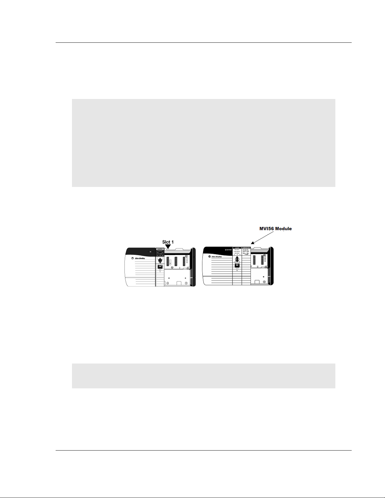
1.4 Installing the Module in the Rack
If you have not already installed and configured your ControlLogix processor and
power supply, please do so before installing the MVI56-PDPMV1 module. Refer
to your Rockwell Automation product documentation for installation instructions.
Warning: You must follow all safety instructions when installing this or any other electronic
devices. Failure to follow safety procedures could result in damage to hardware or data, or even
serious injury or death to personnel. Refer to the documentation for each device you plan to
connect to verify that suitable safety procedures are in place before installing or servicing the
device.
Warning: When you insert or remove the module while backplane power is on, an electrical arc
can occur. This could cause an explosion in hazardous location installations. Verify that power is
removed or the area is non-hazardous before proceeding. Repeated electrical arcing causes
excessive wear to contacts on both the module and its mating connector. Worn contacts may
create electrical resistance that can affect module operation.
1 Turn power OFF.
2 Align the module with the top and bottom guides, and slide it into the rack
until the module is firmly against the backplane connector.
3 With a firm but steady push, snap the module into place.
4 Check that the holding clips on the top and bottom of the module are securely
in the locking holes of the rack.
5 Make a note of the slot location. You must identify the slot in which the
module is installed in order for the sample program to work correctly. Slot
numbers are identified on the green circuit board (backplane) of the
ControlLogix rack.
6 Turn power ON.
Note: If you insert the module improperly, the system may stop working, or may behave
unpredictably.
ProSoft Technology, Inc. Page 15 of 255
March 22, 2011
Page 16

Start Here MVI56-PDPMV1 ♦ ControlLogix Platform
User Manual PROFIBUS DPV1 Master
1.5 Choosing Sample Ladder Logic For Your Application
The sample program for your MVI56-PDPMV1 module includes custom tags,
data types and ladder logic for data I/O, status and alarm monitoring, and
mailbox messaging. For most applications, you can run the sample ladder
program without modification, or, for advanced applications, you can incorporate
the sample program into your existing application.
NOTE: ControlLogix firmware versions 15 or earlier do not support Add-On Instructions (AOIs).
For these applications, you will need to use the plain ladder logic sample programs.
For applications with ControlLogix firmware version 16 or newer, you can use the supplied AOI
samples, which encapsulate the ladder logic, controller tags, and user-defined data types into one
convenient import file.
SPECIAL NOTE: For AOI applications created using ProSoft Configuration Builder (PCB) version
2.2.0 or later, the following process of sample ladder selection is not necessary. PCB versions
2.2.0 and up allow you to export custom-made RSLogix 5000 .L5X Rung Import files that precisely
match the module's configuration. Selecting and modifying sample logic will not be required if you
use PCB 2.2.0. or later and follow the procedure found in the topic, Export the Processor Files for
PCB v2.2.0 or later (page 107). For more details, see the section, Using the MVI56-PDPMV1 AddOn Instructions (page 24).
The inRAx Solutions CD provides several versions of the sample ladder logic.
The version number appended to the sample file name (for example, "_v13" or
"_v15") indicates which ControlLogix firmware version the sample program was
created to match. It is best if the ControlLogix processor firmware version and
sample program version match. However, RSLogix 5000 can convert an older
version sample to a later ControlLogix firmware version, if necessary.
The following criteria determine which sample program to select:
o
Processor Firmware Version
o
MVI56-PDPMV1 module firmware version
o
MVI56-PDPMV1 mode used (FLEX or LEGACY)
Note: FLEX mode is available only for module firmware versions 1.21 or later.
The next few topics will help you determine which sample programs will work
best for your application.
Page 16 of 255 ProSoft Technology, Inc.
March 22, 2011
Page 17
MVI56-PDPMV1 ♦ ControlLogix Platform Start Here
PROFIBUS DPV1 Master User Manual
1.5.1 Determining the Firmware Version of Your Processor
Important: The RSLinx service must be installed and running on your computer in order for
RSLogix to communicate with the processor. Refer to your RSLinx and RSLogix documentation for
help configuring and troubleshooting these applications.
1 Connect an RS-232 serial cable from the COM (serial) port on your PC to the
communication port on the front of the processor.
2 Start RSLogix 5000 and close any existing project that may be loaded.
3 Open the C
establish communication with the processor. This may take a few moments.
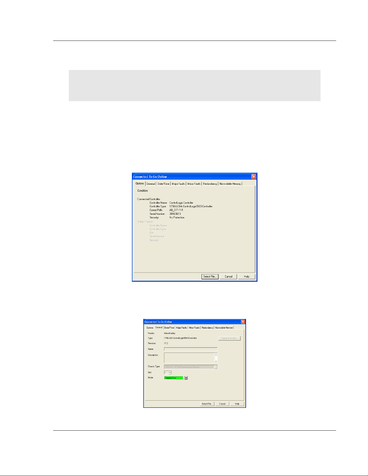
4 When RSLogix has established communication with the processor, the
Connected To Go Online dialog box will open.
OMMUNICATIONS
menu and choose GO O
NLINE
. RSLogix will
5 In the Connected To Go Online dialog box, click the G
ENERAL
tab. This tab
shows information about the processor, including the Revision (firmware)
version. In the following illustration, the firmware version is 17.2.
ProSoft Technology, Inc. Page 17 of 255
March 22, 2011
Page 18
Start Here MVI56-PDPMV1 ♦ ControlLogix Platform
User Manual PROFIBUS DPV1 Master
1.5.2 Determining the Firmware Version of the MVI56-PDPMV1
Module
There are two ways to verify the module firmware version:
Checking the Version During Power-Up
When the module powers up, it will search for the ControlLogix processor to
establish backplane connectivity. If the correct ladder is not loaded to the
processor, or if the module is not located in the configured slot, or the processor
is missing, the module will not allow access to the debug menu and will print the
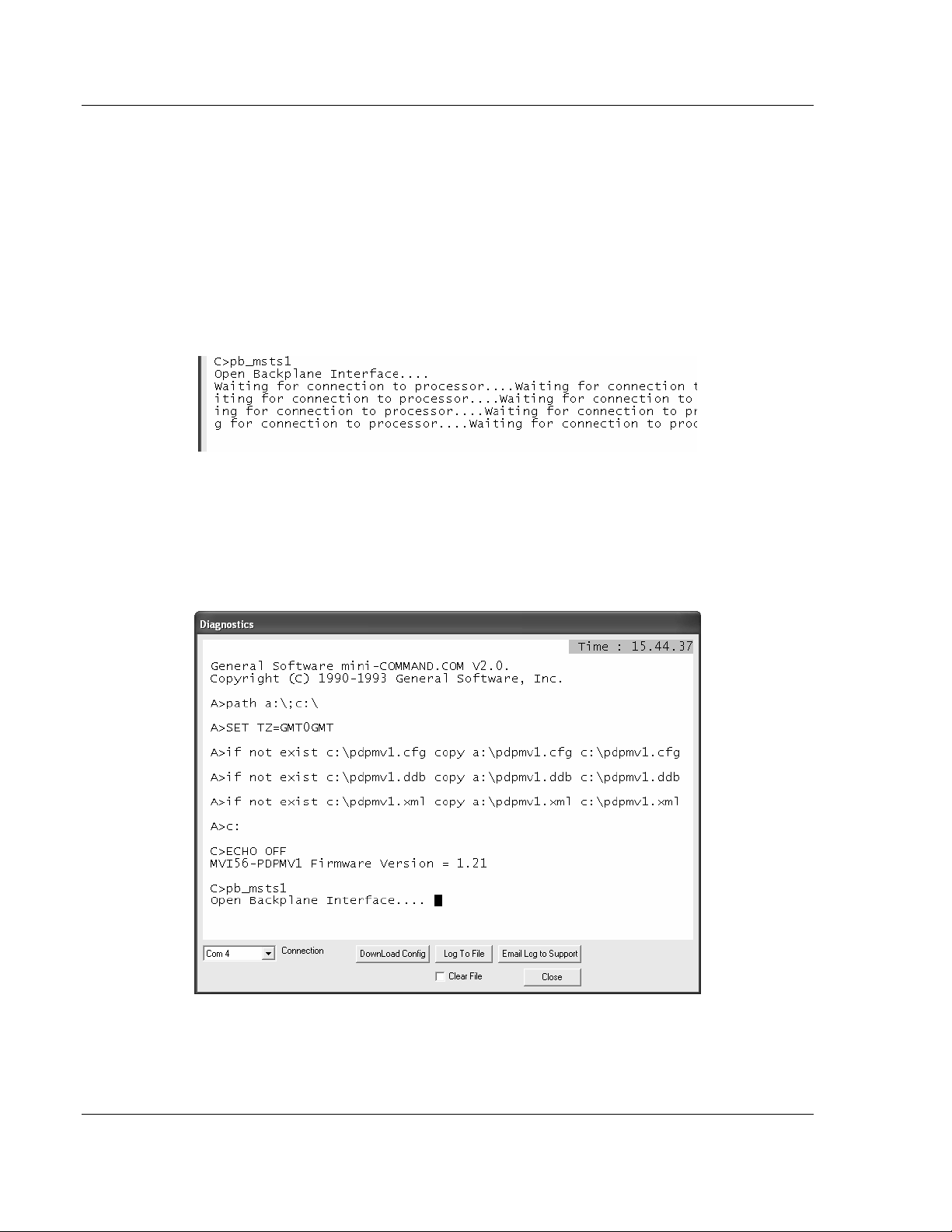
message "Waiting for Connection to the processor…"
Because debug menu access is not allowed at this point, view the debug menu
messages that are printed during power-up for the module firmware version.
Refer to the message that appears just before the message "C>pb_msts1":
If the message "MVI56-PDPMV1 Firmware Version = x.xx" appears on the
screen as shown in the following illustration, the module firmware is version 1.21
or later.
Page 18 of 255 ProSoft Technology, Inc.
March 22, 2011
Page 19
MVI56-PDPMV1 ♦ ControlLogix Platform Start Here
PROFIBUS DPV1 Master User Manual
If the message "MVI56-PDPMV1 Firmware Version = x.xx" does not appear on
the screen, the module firmware version is 0.30.
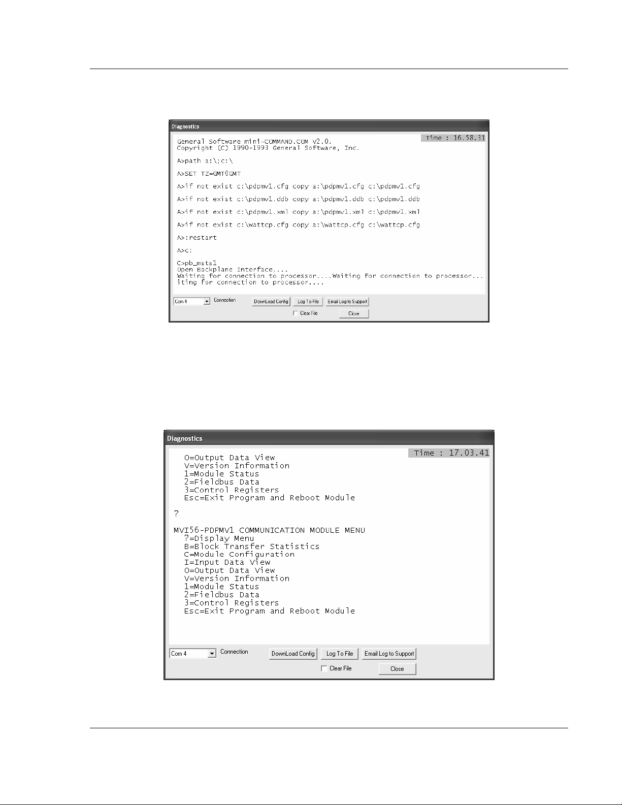
Checking the Version After Power-Up
If the correct sample program (LEGACY or FLEX) is loaded into your processor
and the module is located in same slot that was configured, then after module
power-up it will be possible to access the debug menu through ProSoft
Configuration Builder (PCB).
1 Press [?] to display the main menu:
ProSoft Technology, Inc. Page 19 of 255
March 22, 2011
Page 20
Start Here MVI56-PDPMV1 ♦ ControlLogix Platform
User Manual PROFIBUS DPV1 Master
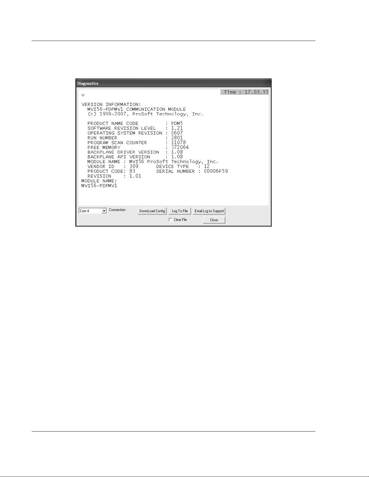
2 Press [V] to display the module version information. Verify "SOFTWARE
REVISION LEVEL" for the module firmware version (1.21 for the example
below):
1.5.3 Determining the Module Mode (LEGACY or FLEX)
There are two versions of the sample program: LEGACY (fixed I/O sizes) and
FLEX (variable I/O sizes) versions.
MVI56-PDPMV1 firmware version 0.30 must use the LEGACY sample
program and fixed I/O sizes.
MVI56-PDPMV1 firmware version 1.21 or later can use either the LEGACY or
FLEX mode sample programs.
For module firmware version 1.21 or later, the U
parameter in ProSoft Configuration Builder selects which mode you will use.
Setting the parameter to YES says to use fixed I/O sizes in LEGACY mode.
Setting the parameter to NO says to use variable I/O sizes in FLEX mode. This
step is described in Select the Connection Parameters for the Module (page 69).
LEGACY mode allows backward compatibility with firmware version 0.30 and
implements the following features:
Fixed backplane I/O block size (input size = 250 words, output size = 248
words)
Status and Mailbox transferred through regular I/O blocks.
SE LEGACY MODE
configuration
Page 20 of 255 ProSoft Technology, Inc.
March 22, 2011
Page 21

MVI56-PDPMV1 ♦ ControlLogix Platform Start Here
PROFIBUS DPV1 Master User Manual
LEGACY mode offers these advantages:
Works with all module firmware versions; use LEGACY mode for backward
compatibility in older applications.
Since all parameters are fixed, configuration is simpler than FLEX mode.
Status data is bought across the backplane as I/O data without the need for
additional logic to trigger MSG instructions.
FLEX mode implements the following features:
Supports variable backplane I/O block sizes (input backplane block size can
be set from 12 words to 250 words; output backplane block size can be set
from 5 to 248 words).
Status, Slave Diagnostic, and Mailbox data transferred through MSG
instructions.
Supports IOT instruction for immediate write of backplane output.
When transfer speed for smaller data configurations is a priority or when
backward compatibility is not required, consider using FLEX mode, which
provides these advantages:
Makes it easier to support installing the module in a remote rack. The flexible
backplane I/O block size allows you to adjust the amount of data to transfer
for any specific remote rack application and optimize network bandwidth
utilization.
Improves backplane I/O block transfer performance by implementing MSG
instructions to retrieve module status. This means regular I/O block transfers
are not needed for status data, so process I/O data can be updated more
often. The same applies to Mailbox MSG data transfers.
Improves backplane performance by implementing the IOT instruction for
Immediate Output Transfers, which overrides the module RPI time and sends
data as fast as possible.
ProSoft Technology, Inc. Page 21 of 255
March 22, 2011
Page 22

Start Here MVI56-PDPMV1 ♦ ControlLogix Platform
User Manual PROFIBUS DPV1 Master
1.5.4 Sample Program Summary
Use the following table to determine which sample program to use for your
application.
MVI56-PDPMV1
Version
0.30 13 - MVI56PDPMV1_LEGACY_v13.ACD -
0.30 15 - MVI56PDPMV1_LEGACY_v15.ACD -
0.30 16 - MVI56PDPMV1_LEGACY_v16.ACD MVI56PDPMV1_LEGACY_v1_3.L5X
1.21 or later 13 Y (LEGACY) MVI56PDPMV1_LEGACY_v13.ACD -
1.21 or later 15 Y (LEGACY) MVI56PDPMV1_LEGACY_v15.ACD -
1.21 or later 16 Y (LEGACY) MVI56PDPMV1_LEGACY_v16.ACD MVI56PDPMV1_LEGACY_v1_3.L5X
1.21 or later 17 Y (LEGACY) MVI56PDPMV1_LEGACY_v17.ACD MVI56PDPMV1_LEGACY_v1_3.L5X
1.21 or later 13 N (FLEX) MVI56PDPMV1_FLEX_v13.ACD -
1.21 or later 15 N (FLEX) MVI56PDPMV1_FLEX_v15.ACD -
1.21 or later 16 N (FLEX) MVI56PDPMV1_FLEX_v16.ACD MVI56PDPMV1_FLEX_v1_2.L5X
1.21 or later 17 N (FLEX) MVI56PDPMV1_FLEX_v17.ACD MVI56PDPMV1_FLEX_v1_2.L5X
Note: For ControlLogix version 16, you will use the Add-On Instruction (AOI) rung import (.L5X)
files, which encapsulate all the required ladder logic, controller tags, and user-defined data types
into a single import file; or you can use the version 16 ladder logic sample files (.ACD), which
already have the AOI files imported. The plain ladder logic sample files (.ACD) for versions 13 and
15 use the same logic as the AOI versions but display them as standard ladder logic. The separate
AOI .L5K file exists to make it easier to import the sample application into an existing project or
new project file. You do not need to import the AOI .L5K files into any of the .ACD ladder logic
sample programs. ControlLogix versions 15 and earlier do not support Add-On Instructions; so do
not try to import the AOI .L5K files into those older versions of RSLogix 5000.
For ControlLogix firmware version 16, refer to Using the MVI56-PDPMV1 Add-On Instructions
(page 24).
For ControlLogix firmware version 15 or older, Using the MVI56-PDPMV1 Sample Ladder
Logic (page 23).
ControlLogix
Version
Use Legacy
Mode
parameter
value
Sample Ladder Add-On Instruction
Page 22 of 255 ProSoft Technology, Inc.
March 22, 2011
Page 23

MVI56-PDPMV1 ♦ ControlLogix Platform Start Here
PROFIBUS DPV1 Master User Manual
1.6 Using the MVI56-PDPMV1 Sample Ladder Logic
If you will be using ControlLogix firmware versions 16 or higher, you may skip to
the section on Using the MVI56-PDPMV1 Add-On Instructions (page 24).
If you will be using ControlLogix firmware versions 13 or 15, then follow this
procedure:
1 Copy any of the sample programs you may want to use from the distribution
CD in a convenient folder on your local PC hard drive.
2 Start RSLogix 5000 and close any project or programs that may open
automatically when the program starts.
3 On the F
4 Browse to the location where you saved the sample program files on your
local drive and select (left-mouse-click) the one that matches your firmware
version of your ControlLogix processor firmware.
5 Left-click the O
6 RSLogix will load the sample program.
The next step is to configure the correct controller type and slot number for your
application. For details, skip to the section on Common Settings for All Sample
Programs (page 65).
If you want to add the sample file to an existing application, do the following:
1 Open the RSLogix 5000 project .ACD file you wish to use.
2 In a separate instance of RSLogix 5000, open the sample ladder logic you
wish to use.
3 Follow the procedures for adding a Module to the project and setting
Connection Parameters, as found in Creating the MVI56-PDPMV1 Module
Profile - Legacy (page 25), Creating the MVI56-PDPMV1 Module Profile Flex (page 50), and Common Settings for All Sample Programs (page 65).
4 Manually copy the user-defined data types from the sample program and
paste them into your existing application.
5 Manually copy the controller tags from the sample program and paste them
into your existing application.
6 Manually copy the ladder logic tasks and rungs from the sample program and
paste them into your existing application.
ILE
menu, click the O
PEN
button.
PEN
button.
ProSoft Technology, Inc. Page 23 of 255
March 22, 2011
Page 24

Start Here MVI56-PDPMV1 ♦ ControlLogix Platform
User Manual PROFIBUS DPV1 Master
1.7 Using the MVI56-PDPMV1 Add-On Instruction
Note: This section applies only for applications with ControlLogix firmware version 16 or higher.
For earlier firmware versions, refer to Using the MVI56-PDPMV1 Sample Ladder Logic (page 23).
The Add-On Instruction (AOI) is supplied already installed as part of a complete
.ACD program file and also as an .L5X ladder import file that can be imported
into an existing or new application. Importing the AOI reduces module setup time
and simplifies your application logic. The .L5X file automatically imports the
following components into an application:
User-defined data types
Controller tags and tag arrays
Add-On Instruction logic
Ladder rung required to call the Add-On Instruction
This section will show the procedure on how to import the Add-On Instruction into
your existing ladder for both module modes (LEGACY or FLEX).
1.7.1 LEGACY Sample Add-On Instruction Import Procedure
Note: This section applies only if your application meets one or more of the following conditions:
MVI56-PDPMV1 module firmware version 0.30
MVI56-PDPMV1 module firmware version 1.21 (or later) AND configured in LEGACY mode
(U
SE LEGACY MODE
= YES)
Before You Begin
The following file is required before you start this procedure. Copy the file from
the ProSoft Solutions CD-ROM, or download it from
www.prosoft-technology.com.
File Name Description
MVI56PDPMV1_LEGACY_v*.L5X
(where * is the current sample
program version number)
L5X file containing Add-On Instruction, user-defined data
types, controller tags and tag arrays, and ladder logic required
to set up the MVI56-PDPMV1 module in Legacy mode
Page 24 of 255 ProSoft Technology, Inc.
March 22, 2011
Page 25
MVI56-PDPMV1 ♦ ControlLogix Platform Start Here
PROFIBUS DPV1 Master User Manual
Creating a New RSLogix5000 Project - Legacy
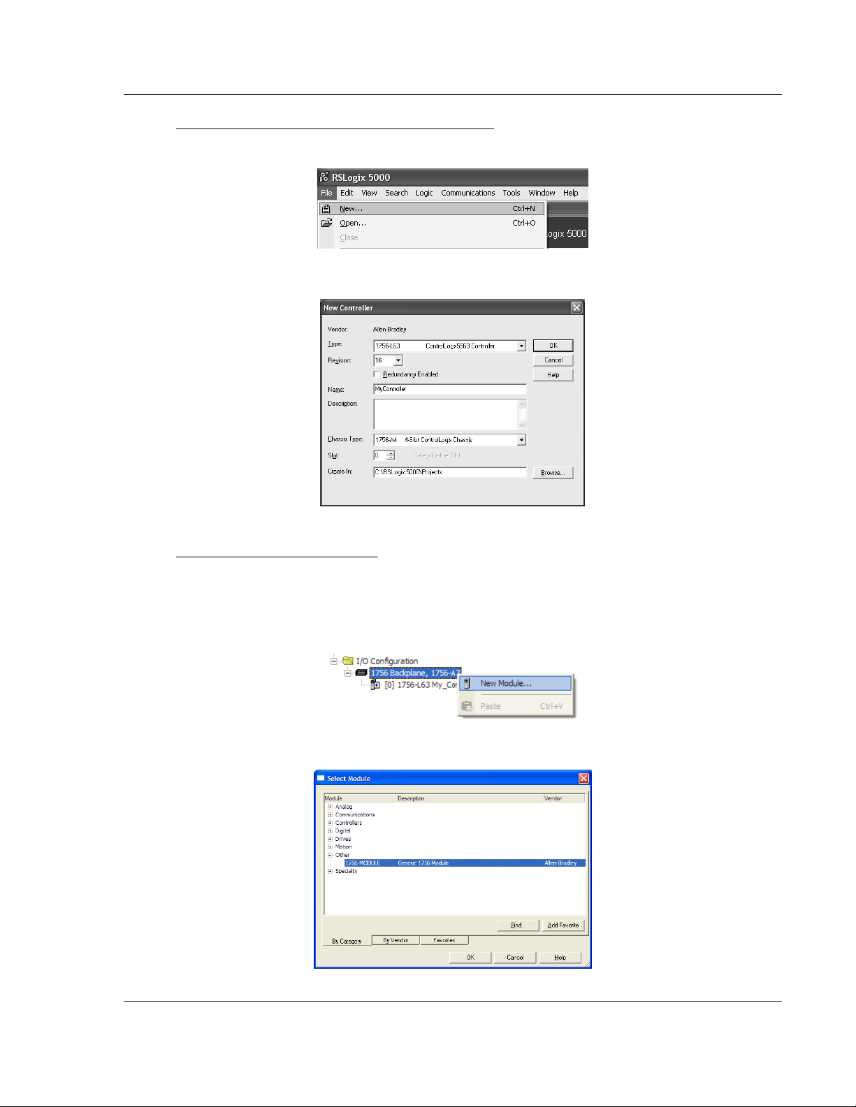
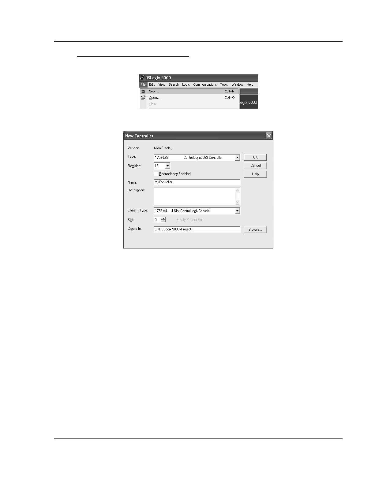
1 Open the File menu, and then choose NEW.
2 Select Revision 16.
Creating the Module - Legacy
1 Add the MVI56-PDPMV1 module to the project.
In the Controller Organization window, select I/O C
ONFIGURATION
the right mouse button to open a shortcut menu. On the shortcut menu,
choose N
EW MODULE
.
This action opens the Select Module dialog box.
and click
ProSoft Technology, Inc. Page 25 of 255
March 22, 2011
Page 26
Start Here MVI56-PDPMV1 ♦ ControlLogix Platform
User Manual PROFIBUS DPV1 Master
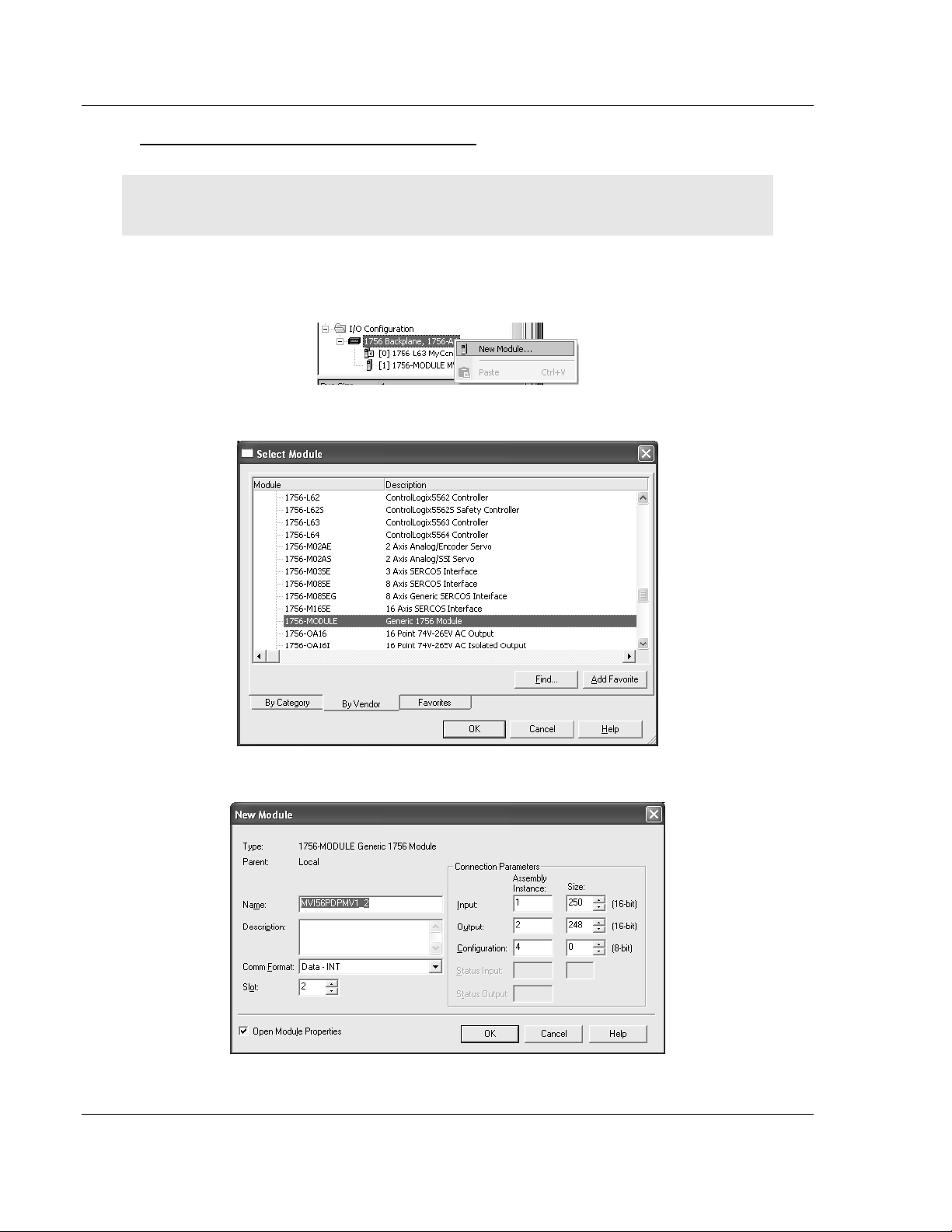
2 Select the 1756-M
ODULE (GENERIC
1756 M
ODULE)
from the list and click OK.
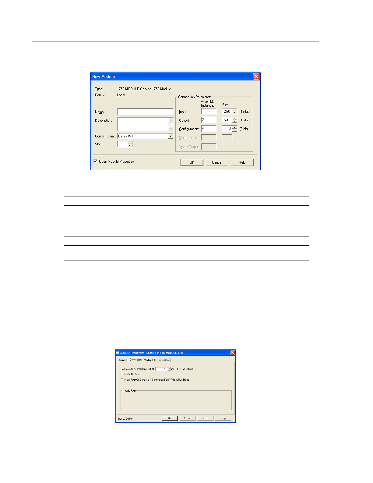
This action opens the New Module dialog box.
3 Set the Module Properties values as follows:
Parameter Value
Name Enter a module identification string. Example:
MVI56PDPMV1
Description Enter a description for the module. Example: ProSoft
communication module for PROFIBUS communication.
Comm Format
Slot Enter the slot number in the rack where the MVI56-
Input Assembly Instance
Input Size
Output Assembly Instance
Output Size
Configuration Assembly Instance
Configuration Size
Select DATA-INT
PDPMV1 module is located.
1
250
2
248
4
0
4 On the Connection tab, set the RPI value for your project. Click OK to
confirm.
Page 26 of 255 ProSoft Technology, Inc.
March 22, 2011
Page 27
MVI56-PDPMV1 ♦ ControlLogix Platform Start Here
PROFIBUS DPV1 Master User Manual
Now the MVI56-PDPMV1 module will be visible in the I/O Configuration section.
Importing the Ladder Rung - LEGACY
Note: ProSoft Configuration Builder (PCB), version 2.2.0, or higher, will allow you to export an .L5X
rung import file based on the configuration information you enter in PCB. When using LEGACY
mode, these custom export files will be very similar to the provided sample LEGACY AOI Rung
Import files.
For additional information on how to export custom-made .L5X files from PCB, please see
Exporting the Processor Files (page 105).
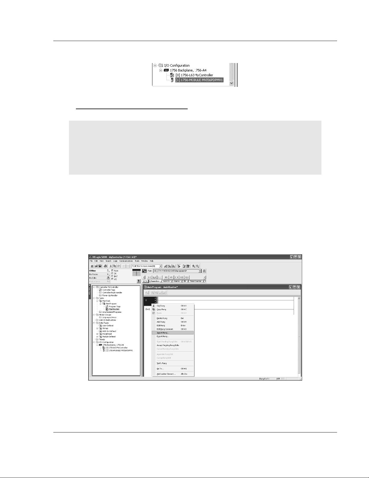
1 Open your application in RSLogix 5000.
2 Expand the Tasks folder, and then expand the MainTask folder.
3 On the MainProgram folder, click the right mouse button to open a shortcut
menu. On the shortcut menu, choose N
EW ROUTINE
.
4 In the New Routine dialog box, enter the name and description of your
routine, and then click OK.
5 Select an empty rung in the new routine, and then click the right mouse
button to open a shortcut menu. On the shortcut menu, choose I
MPORT RUNG
.
ProSoft Technology, Inc. Page 27 of 255
March 22, 2011
Page 28
Start Here MVI56-PDPMV1 ♦ ControlLogix Platform
User Manual PROFIBUS DPV1 Master
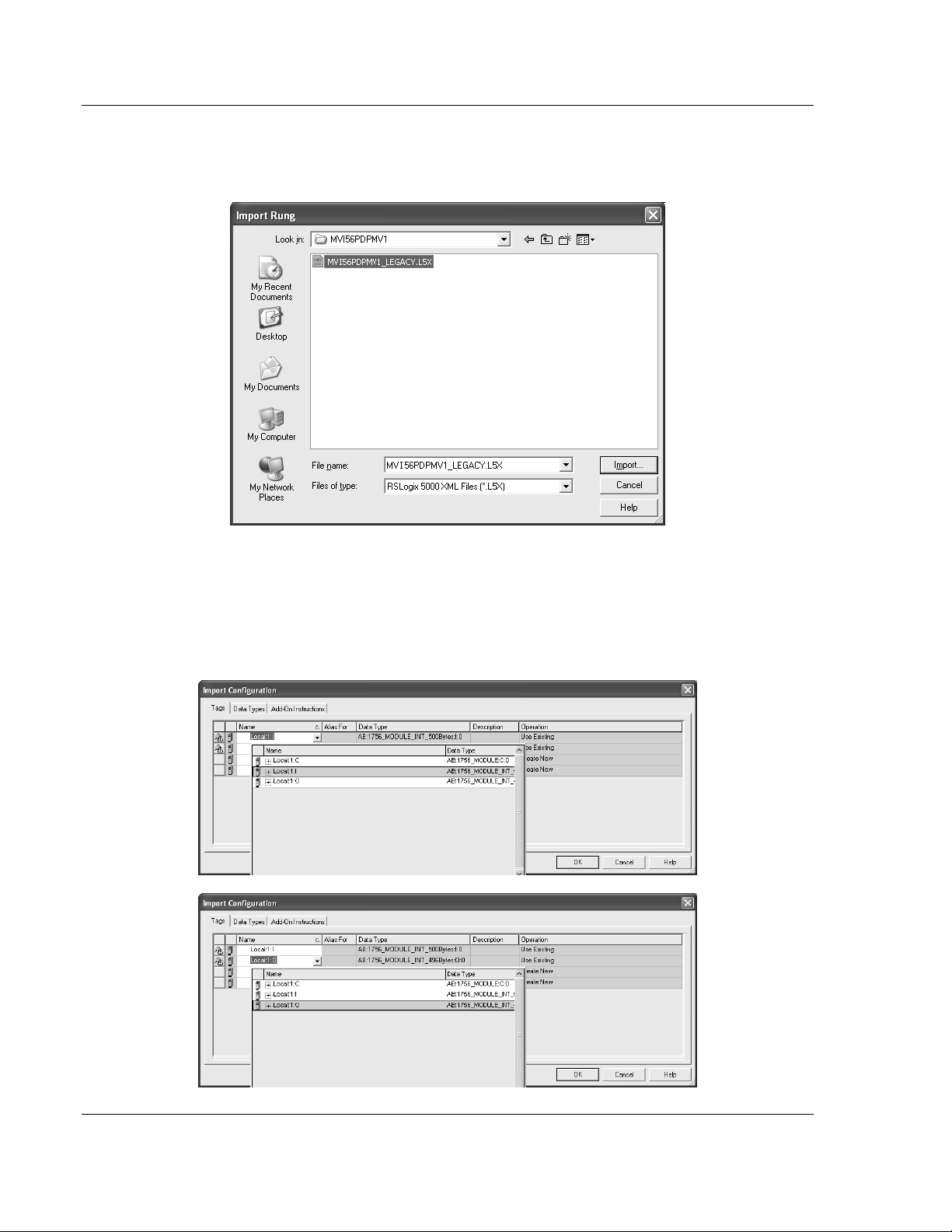
6 Select the MVI56PDPMV1_LEGACY_v*.ACD standard sample file, or the
MVI56PDPMV1_LEGACY_AddOn_Rung_v1_2.L5X custom file you exported
from PCB, and click the I
MPORT
button.
7 A window will be displayed showing the controller tags to be created during
the import procedure.
8 If you are using the module in a different slot (or remote rack) select the
correct connection input and output variables to provide the correct path to
the module. If your module is located in Slot 1 of the local rack, this step is
not required.
Page 28 of 255 ProSoft Technology, Inc.
March 22, 2011
Page 29
MVI56-PDPMV1 ♦ ControlLogix Platform Start Here
PROFIBUS DPV1 Master User Manual
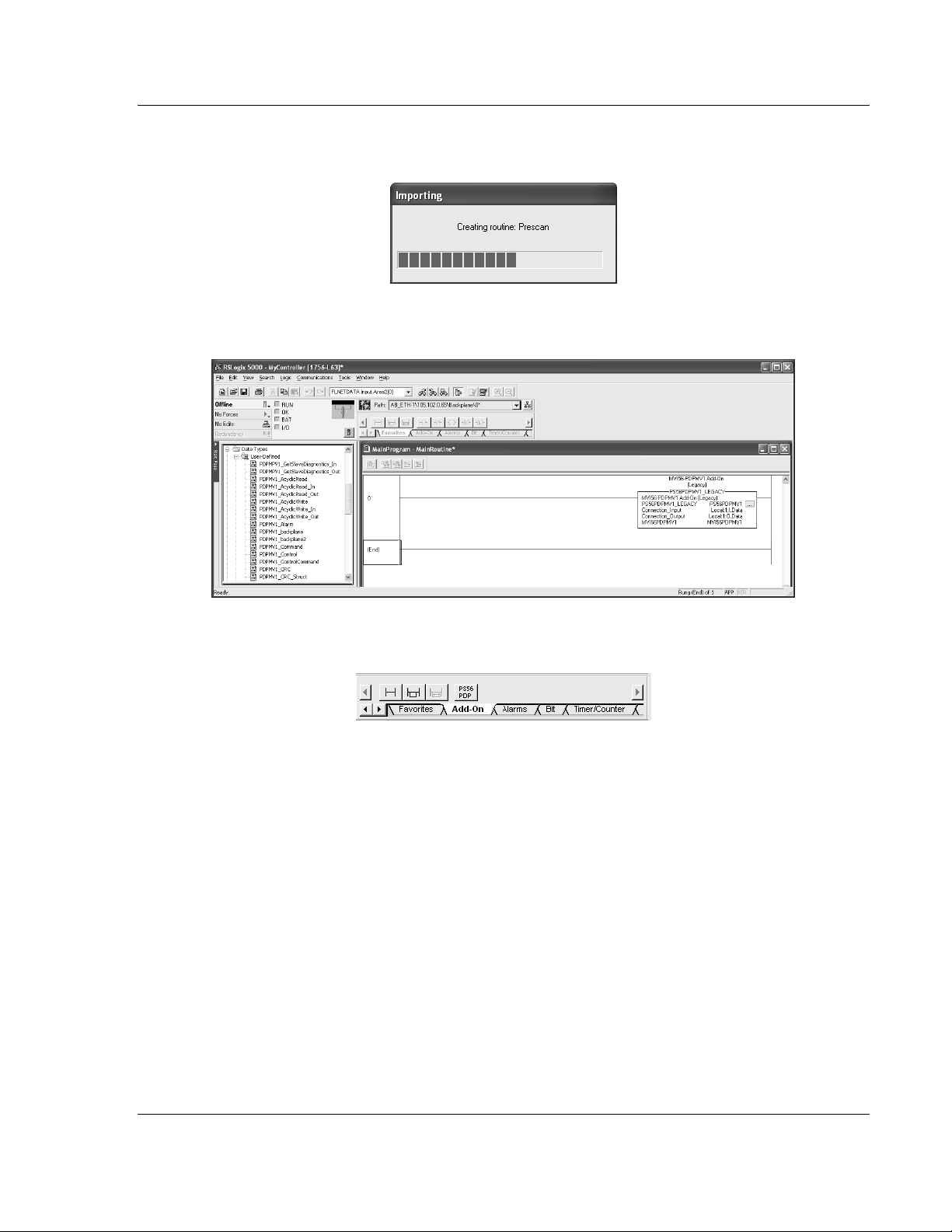
9 Click OK to confirm the import. RSLogix will indicate that the import is in
progress:
10 When the import is completed, the new rung with the Add-On Instruction will
be visible as shown in the following illustration.
The procedure has also imported new user-defined data types, controller tags
and tag arrays, and the Add-On Instruction to be used at your project.
ProSoft Technology, Inc. Page 29 of 255
March 22, 2011
Page 30
Start Here MVI56-PDPMV1 ♦ ControlLogix Platform
User Manual PROFIBUS DPV1 Master
Adding Multiple Modules (Optional) - Legacy
Important: If your application requires more than one MVI56-PDPMV1 module into the same
project, follow the steps below.
1 In the I/O Configuration folder, click the right mouse button to open a shortcut
menu, and then choose N
EW MODULE
.
2 Select 1756-MODULE.
3 Fill the module properties as follows:
Page 30 of 255 ProSoft Technology, Inc.
March 22, 2011
Page 31

MVI56-PDPMV1 ♦ ControlLogix Platform Start Here
PROFIBUS DPV1 Master User Manual
Parameter Value
Name Enter a module identification string. Example: MVI56PDPMV1_2
Description Enter a description for the module. Example: ProSoft communication
module for PROFIBUS communication.
Comm Format
Slot Enter the slot number in the rack where the MVI56-PDPMV1 module is
Input Assembly
Instance
Input Size Enter the number of words per backplane input block to copy from the
Output Assembly
Instance
Output Size Enter the number of words per backplane output block to copy from the
Configuration
Assembly Instance
Configuration Size
Select DATA-INT
located.
1
module to the processor. The allowable range is from 12 to 250 words.
Each input block will reserve 8 words for general purposes (CRC, block/CIP
handshaking). The remainder is reserved for PROFIBUS input data.
2
module to the processor. The allowable range is from 5 to 248 words. Each
output block will reserve 5 words for general purposes (CRC and block
handshaking). The remainder is reserved for PROFIBUS output data.
4
0
4 Click OK to confirm. The new module is now visible:
5 Expand the Tasks folder, and then expand the MainTask folder.
6 On the MainProgram folder, click the right mouse button to open a shortcut
menu. On the shortcut menu, choose N
EW ROUTINE
.
7 In the New Routine dialog box, enter the name and description of your
routine, and then click OK.
ProSoft Technology, Inc. Page 31 of 255
March 22, 2011
Page 32

Start Here MVI56-PDPMV1 ♦ ControlLogix Platform
User Manual PROFIBUS DPV1 Master
8 Select an empty rung in the new routine, and then click the right mouse
button to open a shortcut menu. On the shortcut menu, choose I
MPORT RUNG
.
9 Select the file PS56PDPMV1_LEGACY_v*.L5X
Page 32 of 255 ProSoft Technology, Inc.
March 22, 2011
Page 33

MVI56-PDPMV1 ♦ ControlLogix Platform Start Here
PROFIBUS DPV1 Master User Manual
10 The following window will be displayed showing the tags to be imported:
11 Associate the I/O connection variables to the correct module. The default
values are Local:1:I and Local:1:O so these require change.
ProSoft Technology, Inc. Page 33 of 255
March 22, 2011
Page 34

Start Here MVI56-PDPMV1 ♦ ControlLogix Platform
User Manual PROFIBUS DPV1 Master
12 Change the default tags MVI56PDPMV1 and PS56PDPMV1 to avoid conflict
with existing tags by append the string "_2" (or any other unique identifier
string) as follows:
13 Click OK to confirm.
The setup procedure is now complete. Save the project and download the
application to your ControlLogix processor.
Page 34 of 255 ProSoft Technology, Inc.
March 22, 2011
Page 35

MVI56-PDPMV1 ♦ ControlLogix Platform Start Here
PROFIBUS DPV1 Master User Manual
Adding MVI56-PDPMV1 Logic To Existing Applications
Perform the following steps to add the sample ladder logic into your existing
application. The controller tags and user-defined data types provided with the
sample ladder logic are critical to incorporating the MVI56-PDPMV1 into your
application.
Legacy Mode
Note: You cannot perform this procedure while you are online to the controller.
1 Open your application in RSLogix 5000.
2 In the Controller Organization list in RSLogix 5000, click the right mouse
button on the I/O Configuration option to open a shortcut menu. On the
shortcut menu, choose N
EW MODULE
. This action opens the Select Module
Type dialog box.
3 In the Select Module Type dialog box, select 1756-M
M
ODULE
) from the list and, and then click OK. This action opens the Module
ODULE (GENERIC
1756
Properties dialog box.
ProSoft Technology, Inc. Page 35 of 255
March 22, 2011
Page 36

Start Here MVI56-PDPMV1 ♦ ControlLogix Platform
User Manual PROFIBUS DPV1 Master
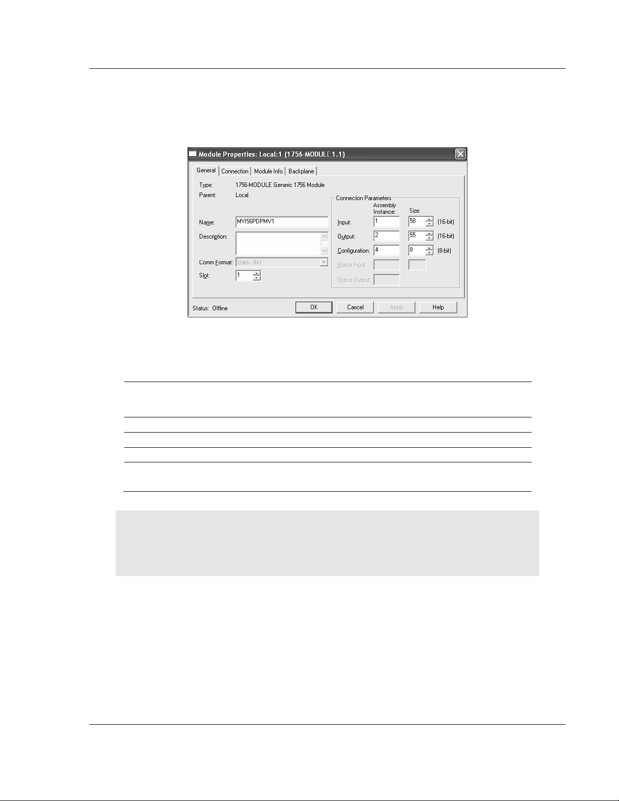
4 In the Module Properties dialog box, enter the N
AME, DESCRIPTION
and S
LOT
options for your application, using the examples in the following illustration.
You must select the C
OMM FORMAT
as D
ATA -
INT in the dialog box. Failure to
set the correct parameters will result in backplane communication problems
between the module and the processor.
5 Click the C
MS
as shown in the following illustration.
ONNECTION
tab and change the Requested Packet Interval to 5.0
6 Click F
INISH
to save the module into your existing application.
7 Next, open the sample program in RSLogix 5000. Refer to Open the Sample
Program in RSLogix (page 16) to determine the correct version of the sample
program to use.
Page 36 of 255 ProSoft Technology, Inc.
March 22, 2011
Page 37

MVI56-PDPMV1 ♦ ControlLogix Platform Start Here
PROFIBUS DPV1 Master User Manual
8 Copy the ladder logic routines from the sample ladder logic into your existing
application. Repeat this step for each subroutine.
9 Copy and paste each of the user-defined types from the sample ladder logic
into your existing application.
10 Export the controller tags from the sample program (Tools/Export) into a CSV
file, and then import the CSV file (Tools/Import) into your existing application.
ProSoft Technology, Inc. Page 37 of 255
March 22, 2011
Page 38

Start Here MVI56-PDPMV1 ♦ ControlLogix Platform
User Manual PROFIBUS DPV1 Master
1.7.2 FLEX Sample Add-On Instruction Import Procedure
Note: This section applies only if the MVI56-PDPMV1 firmware version is 1.21 (or later) AND
configured in FLEX mode (U
Before You Begin
The following file is required before you start this procedure. Copy the file from
the ProSoft Solutions CD-ROM, or download it from
www.prosoft-technology.com.
File Name Description
PS56PDPMV1_FLEX_v*.L5X
(where * is the current sample
program version number)
Flexible Connection I/O Length Overview
This section describes the flexible backplane connection I/O concept.
The connection parameters may assume values within the following ranges:
Minimum Size
(16-bit)
Input 12 250 [input size - 8] 1
Output 5 248 [bp output size - 5] 2
Configuration 0 0 not used 4
SE LEGACY MODE
L5X file containing Add-On Instruction, user-defined data types,
controller tags, and ladder logic required to set up the MVI56PDPMV1 module
Maximum Size (16bit)
= NO)
Maximum PROFIBUS data count per
block (16-bit)
Assembly
Instance
For applications where the module will be used in the local rack (the same rack
as the ControlLogix processor), use the maximum backplane I/O sizes.
For applications where the module will be used in a remote rack, use the
backplane I/O sizes that will provide optimal network performance (PROFIBUS
and ControlNet or EtherNet/IP).
The configured sizes will have an impact on the number of blocks required to
transfer the entire PROFIBUS I/O database between the ControlLogix processor
and the MVI56-PDPMV1 module. Reducing the number of words per backplane
block may improve the ControlNet or EtherNet/IP network performance.
However, doing so will increase the number of backplane block transfers and
have a negative effect on overall backplane data transfer efficiency.
Page 38 of 255 ProSoft Technology, Inc.
March 22, 2011
Page 39

MVI56-PDPMV1 ♦ ControlLogix Platform Start Here
PROFIBUS DPV1 Master User Manual
IMPORTANT: ControlLogix Version 16 with FLEX Mode
If you change the connection sizes in the module profile, you must also update the following data
types with the new sizes. The connection I/O sizes defined in the module profile must always
match the following user-defined data types:
PDPMV1_C
PDPMV1_C
ONNECTION_INPUT
ONNECTION_OUTPUT
You will also need to adjust limits in some of the ladder logic or AOI logic. For additional details,
see Adjusting the Connection Sizes for Your Application. (page 41)
The array sizes must be modified (in the Data Type column) to match the
connection sizes configured in the module profile. Failure to do so will prevent
the module from establishing backplane communication with the ControlLogix
processor.
Example 1
For the following example, if the module profile is configured as:
ProSoft Technology, Inc. Page 39 of 255
March 22, 2011
Page 40

Start Here MVI56-PDPMV1 ♦ ControlLogix Platform
User Manual PROFIBUS DPV1 Master
Then, the PDPMV1_C
ONNECTION_INPUT
user-defined data type must have an
array size of 250 words, as shown in the following illustration.
And, the PDPMV1_C
ONNECTION_OUTPUT
user-defined data type must have an
array size of 248 words, as shown in the following illustration.
Note: Each backplane block contains certain registers reserved for general purposes (nonPROFIBUS data transfer). The backplane input block reserves 8 words for general purposes and
the backplane output block reserves 5 words. You must subtract these reserved words from the
total I/O block size to calculate the actual number of PROFIBUS I/O data per backplane I/O block
and where the break points between data blocks will be in the PROFIBUS data arrays.
Page 40 of 255 ProSoft Technology, Inc.
March 22, 2011
Page 41

MVI56-PDPMV1 ♦ ControlLogix Platform Start Here
PROFIBUS DPV1 Master User Manual
Adjusting the Connection Sizes for Your Application
Note: ProSoft Configuration Builder (PCB), version 2.2.0, or higher, will automatically make the
following adjustments for you based on the configuration information you enter in PCB. The newer
versions of PCB allow you to export custom-made RSLogix 5000 .L5X Add-On Instruction (AOI)
Rung Import files that are already tailored to your application-specific configuration. These custom
files will be similar to the provided sample AOI Rung Import files but will already include the
adjustments shown in the next few topics. If you use the custom import files, you will not need to
do any of the following; it will be done for you already. If this is the case, all you need to do is
import the custom .L5X file according to the procedure found in Importing the Ladder Rung: FLEX
(page 53).
For additional information on how to export custom-made .L5X files from PCB, please see the
topic, Exporting the Processor Files (page 105).
The information provided in this topic shows you what kind of modifications are being done
automatically for you by PCB. This information can also help you manually edit the standard FLEX
sample files to better fit your application or help you determine what kinds of modifications you
might need to make to any existing applications you may already be using.
1 The AOI Connection Input and Output parameters use certain data type sizes
that must be set based on how you configured the MVI56-PDPMV1 module.
2 In the D
PDPMV1_C
ATA TYPES/USER-DEFINED
ONNECTION_INPUT
data type.
folder, double-click
ProSoft Technology, Inc. Page 41 of 255
March 22, 2011
Page 42

Start Here MVI56-PDPMV1 ♦ ControlLogix Platform
User Manual PROFIBUS DPV1 Master
3 Adjust the array size for your application. The default array size is INT[250]
(maximum size). This example is for 250 input words.
4 In the D
PDPMV1_C
ATA TYPES/USER-DEFINED
ONNECTION_OUTPUT
folder, double-click
data type.
Page 42 of 255 ProSoft Technology, Inc.
March 22, 2011
Page 43

MVI56-PDPMV1 ♦ ControlLogix Platform Start Here
PROFIBUS DPV1 Master User Manual
5 Adjust the array size for your application. The default array size is INT[248]
(maximum size). This example is for 248 output words.
6 The imported ladder rung has also used the default I/O settings (Input Count
= 250 words, Output Count = 248 words). If different values are used, make
the following changes to the ladder logic:
COP Instruction (input)
Change the Length to match the number of input words configured for the
module. The default uses 250 words.
NEQ Instruction
Change the array element as the last element of the connection input array. The
default refers to element 249, since this is the last element of the array of 250
words. For example, if the module connection input is set as 122 words, set the
last element as 121.
ProSoft Technology, Inc. Page 43 of 255
March 22, 2011
Page 44

Start Here MVI56-PDPMV1 ♦ ControlLogix Platform
User Manual PROFIBUS DPV1 Master
COP Instruction (output)
Change the Length to match the number of output words configured for the
module. The default uses 248 words.
Example - FLEX application
For this example, if your application requires the PROFIBUS total data sizes
configured as follows (through the ProSoft Configuration Builder):
PROFIBUS I
PROFIBUS O
NPUT DATA SIZE:
UTPUT DATA SIZE:
100
WORDS
100
WORDS
Then, the following four scenarios illustrate the flexible I/O size functionality
(FLEX), using different backplane I/O sizes for the same PROFIBUS I/O size.
Page 44 of 255 ProSoft Technology, Inc.
March 22, 2011
Page 45

MVI56-PDPMV1 ♦ ControlLogix Platform Start Here
PROFIBUS DPV1 Master User Manual
Scenario 1: The PROFIBUS data fits into one backplane block
This example uses the following backplane configuration:
For this scenario, each backplane block reserves 100 words for PROFIBUS data,
so the data fits into one backplane I/O block. The module will generate two block
IDs, blocks 0 and 1, in order to force a Block ID switch, as required for the ladder
logic to function correctly, but both blocks will contain the same data.
Backplane Block Overview
Block
Number
0 Input 108 100 0 99
1 Input 108 100 0 99
0 Output 105 100 0 99
1 Output 105 100 0 99
Input/
Output
Total word count
in backplane
block
PROFIBUS Data
Word Count in
backplane block
Initial PROFIBUS Data
Word Offset in
backplane block
Last PROFIBUS Data
Word Offset in
backplane block
ProSoft Technology, Inc. Page 45 of 255
March 22, 2011
Page 46

Start Here MVI56-PDPMV1 ♦ ControlLogix Platform
User Manual PROFIBUS DPV1 Master
Scenario 2: The PROFIBUS data fits into two backplane blocks (different PROFIBUS data
count per block)
For this example, we will subtract one word for each I/O backplane block, using
the following backplane configuration:
For this scenario, each backplane block reserves a maximum of 99 words for
PROFIBUS I/O data. The configured PROFIBUS I/O size (100 words) will not fit
into one block, so two backplane input blocks and two backplane output blocks
will be required to transfer the entire PROFIBUS I/O data.
Note: For this scenario, block 0 is no longer required because there are two backplane blocks with
different data.
Backplane Block Overview
Block
Number
1 Input 107 99 0 98
2 Input 107 1 99 99
1 Output 104 99 0 98
2 Output 104 1 99 99
Input/
Output
Total word count in
backplane block
PROFIBUS Data
Word Count in
backplane block
Initial PROFIBUS Data
Word Offset in
backplane block
Last PROFIBUS Data
Word Offset in
backplane block
Note: This configuration would be inefficient and is therefore not recommended. The previous
example is a more efficient configuration that will accomplish the same thing. This example is here
solely to illustrate how changing the I/O sizes without changing the amount of PROFIBUS data to
be transferred will affect the number of I/O data blocks the module will need to transfer.
Page 46 of 255 ProSoft Technology, Inc.
March 22, 2011
Page 47
MVI56-PDPMV1 ♦ ControlLogix Platform Start Here
PROFIBUS DPV1 Master User Manual
Scenario 3: The PROFIBUS data fits into two backplane blocks (same PROFIBUS data count
per block)
For this example, we will split the PROFIBUS data evenly within two backplane
blocks, using the following backplane configuration:
For this scenario, each backplane block reserves 50 words for PROFIBUS I/O
data. The configured PROFIBUS I/O size (100 words) will not fit into one block,
so two backplane input blocks and two backplane output blocks will be required.
Backplane Block Overview
Block
Number
1 Input 58 50 0 49
2 Input 58 50 50 99
1 Output 55 50 0 49
2 Output 55 50 50 99
Input/
Output
Total word count
in backplane
block
PROFIBUS Data
Word Count in
backplane block
Initial PROFIBUS Data
Word Offset in
backplane block
Last PROFIBUS Data
Word Offset in
backplane block
Note: This configuration would be inefficient and is therefore not recommended. The first example
(Scenario 1) is a more efficient configuration that will accomplish the same thing. This example is
here solely to illustrate how changing the I/O sizes without changing the amount of PROFIBUS
data to be transferred will affect the number of I/O data blocks the module will need to transfer.
ProSoft Technology, Inc. Page 47 of 255
March 22, 2011
Page 48

Start Here MVI56-PDPMV1 ♦ ControlLogix Platform
User Manual PROFIBUS DPV1 Master
Scenario 4: The PROFIBUS data fits into ten backplane blocks (same PROFIBUS data count
per block)
For this scenario, each backplane block reserves 10 words for PROFIBUS I/O
data. The configured PROFIBUS I/O size (100 words) will not fit into one block,
so ten backplane input blocks and ten backplane output blocks will be required.
Backplane Block Overview
Block
Number
1 Input 18 10 0 9
2 Input 18 10 10 19
3 Input 18 10 20 29
4 Input 18 10 30 39
5 Input 18 10 40 49
6 Input 18 10 50 59
7 Input 18 10 60 69
8 Input 18 10 70 79
9 Input 18 10 80 89
10 Input 18 10 90 99
1 Output 15 10 0 9
2 Output 15 10 10 19
3 Output 15 10 20 29
4 Output 15 10 30 39
5 Output 15 10 40 49
6 Output 15 10 50 59
7 Output 15 10 60 69
8 Output 15 10 70 79
9 Output 15 10 80 89
10 Output 15 10 90 99
Input/
Output
Total word count in
Backplane block
PROFIBUS Data
Word Count in
backplane block
Initial PROFIBUS
Data Word Offset in
backplane block
Last PROFIBUS Data
Word Offset in
backplane block
Note: This configuration would be extremely inefficient and is therefore not recommended. The first
example (Scenario 1) is a more efficient configuration that will accomplish the same thing much
faster with one backplane transfer. This example is here solely to illustrate how changing the I/O
sizes without changing the amount of PROFIBUS data to be transferred will affect the number of
I/O data blocks the module will need to transfer.
Page 48 of 255 ProSoft Technology, Inc.
March 22, 2011
Page 49
MVI56-PDPMV1 ♦ ControlLogix Platform Start Here
PROFIBUS DPV1 Master User Manual
Creating a New RSLogix5000 Project
1 Open the File menu and then choose NEW.
2 Select Revision 16.
ProSoft Technology, Inc. Page 49 of 255
March 22, 2011
Page 50

Start Here MVI56-PDPMV1 ♦ ControlLogix Platform
User Manual PROFIBUS DPV1 Master
Creating the MVI56-PDPMV1 Module Profile - Flex
1 Right-click I/O C
ONFIGURATION
and then choose N
EW MODULE
.
2 Select 1756-MODULE.
Page 50 of 255 ProSoft Technology, Inc.
March 22, 2011
Page 51

MVI56-PDPMV1 ♦ ControlLogix Platform Start Here
Parameter
PROFIBUS DPV1 Master User Manual
3 Fill the module properties as follows:
Value
Name Enter a module identification string. Example: MVI56PDPMV1
Description Enter a description for the module. Example: ProSoft communication
module for PROFIBUS communication.
Comm Format
Slot Enter the slot number in the rack where the MVI56-PDPMV1 module is
Input Assembly
Instance
Input Size Enter the number of words per backplane input block to copy from the
Output Assembly
Instance
Output Size Enter the number of words per backplane output block to copy from the
Configuration
Assembly Instance
Configuration Size
Select DATA-INT
located.
1
module to the processor. The allowable range is from 12 to 250 words.
Each input block will reserve 8 words for general purposes (CRC, block/CIP
handshaking). The remainder is reserved for PROFIBUS input data.
2
module to the processor. The allowable range is from 5 to 248 words. Each
output block will reserve 5 words for general purposes (CRC and block
handshaking). The remainder is reserved for PROFIBUS output data.
4
0
4 The following illustration shows an example for a local rack application where
the module was set with the maximum backplane I/O sizes (250/248 words).
5 Click the C
ONNECTION
tab, and then enter the Requested Package Interval
(RPI) value.
o
If the module is located in the local rack (same rack where the processor
is located) or in a remote rack connected through EtherNet/IP adapters,
select the maximum value of 750
o
If the module is located in a remote rack connected through ControlNet
adapters, adjust the RPI time to be not less than 5
MS
.
MS
and not less than
(and, preferably, some even multiple of) the RSNetWorx for ControlNet
Network Update Time (NUT).
ProSoft Technology, Inc. Page 51 of 255
March 22, 2011
Page 52

Start Here MVI56-PDPMV1 ♦ ControlLogix Platform
User Manual PROFIBUS DPV1 Master
6 Click OK to confirm.
Now the MVI56-PDPMV1 module will be visible in the I/O Configuration section.
Page 52 of 255 ProSoft Technology, Inc.
March 22, 2011
Page 53

MVI56-PDPMV1 ♦ ControlLogix Platform Start Here
PROFIBUS DPV1 Master User Manual
Importing the Ladder Rung - Flex
1 Open your application in RSLogix 5000.
2 Expand the Tasks folder, and then expand the MainTask folder.
3 In the MainProgram folder, select an empty rung, and then click the right
mouse button to open a shortcut menu. On the shortcut menu, choose
I
MPORT RUNG
.
4 Select the PS56PDPMV1_FLEX_v*.L5X standard sample file, or the
MVI56PDPMV1_FLEX_AddOn_Rung_v1_2.L5X custom file you exported
from PCB, and click the I
MPORT
button.
ProSoft Technology, Inc. Page 53 of 255
March 22, 2011
Page 54

Start Here MVI56-PDPMV1 ♦ ControlLogix Platform
User Manual PROFIBUS DPV1 Master
5 The following window will be displayed showing the controller tags associated
with the project. The I/O connection parameters will be set (as default) as
L
OCAL
:1:I and L
OCAL
:1:O, which assumes that the module is located at the
local rack and Slot 1.
6 If your module is located in a different slot or in a remote rack, modify the
parameters to set the correct path to the module, as follows:
Page 54 of 255 ProSoft Technology, Inc.
March 22, 2011
Page 55

MVI56-PDPMV1 ♦ ControlLogix Platform Start Here
PROFIBUS DPV1 Master User Manual
7 Click OK to confirm the import.
8 The new rung will be now visible in the ladder logic showing also the
PS56PDPMV1_FLEX Add-On Instruction.
9 The procedure has also imported new user-defined data types, controller
tags, and controller tag arrays. The new Add-On Instruction can also be used
through the new toolbar button (at Add-On tab).
ProSoft Technology, Inc. Page 55 of 255
March 22, 2011
Page 56

Start Here MVI56-PDPMV1 ♦ ControlLogix Platform
User Manual PROFIBUS DPV1 Master
Adding Multiple Modules (Optional) - Flex
Important: If your application requires more than one MVI56-PDPMV1 module into the same
project, follow the steps below.
1 In the I/O Configuration folder, click the right mouse button to open a shortcut
menu, and then choose N
EW MODULE
.
2 Select 1756-MODULE.
Page 56 of 255 ProSoft Technology, Inc.
March 22, 2011
Page 57
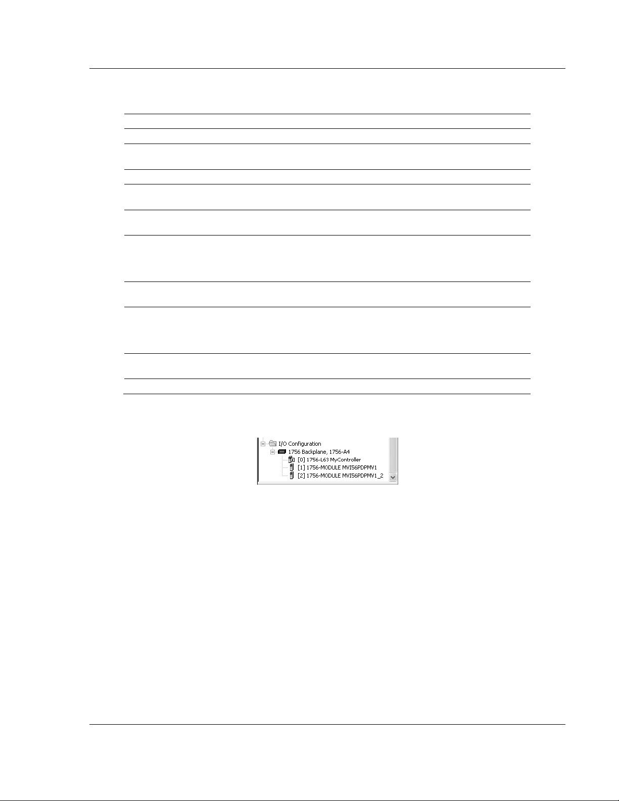
MVI56-PDPMV1 ♦ ControlLogix Platform Start Here
PROFIBUS DPV1 Master User Manual
3 Fill the module properties as required:
Parameter Value
Name Enter a module identification string. Example: MVI56PDPMV1_2
Description Enter a description for the module. Example: ProSoft communication
module for PROFIBUS communication.
Comm Format
Slot Enter the slot number in the rack where the MVI56-PDPMV1 module is
Input Assembly
Instance
Input Size Enter the number of words per backplane input block to copy from the
Output Assembly
Instance
Output Size Enter the number of words per backplane output block to copy from the
Configuration
Assembly Instance
Configuration Size
Select DATA-INT
located.
1
module to the processor. The allowable range is from 12
Each input block will reserve 8 words for general purposes (CRC, block/CIP
handshaking). The remainder is reserved for PROFIBUS input data.
2
module to the processor. The allowable range is from 5
output block will reserve 5 words for general purposes (CRC and block
handshaking). The remainder is reserved for PROFIBUS output data.
4
0
TO
250 words.
TO
248 words. Each
4 Click OK to confirm. The new module is now visible:
5 Expand the Tasks folder, and then expand the MainTask folder.
6 On the MainProgram folder, click the right mouse button to open a shortcut
menu. On the shortcut menu, choose N
EW ROUTINE
.
7 In the New Routine dialog box, enter the name and description of your
routine, and then click OK.
ProSoft Technology, Inc. Page 57 of 255
March 22, 2011
Page 58

Start Here MVI56-PDPMV1 ♦ ControlLogix Platform
User Manual PROFIBUS DPV1 Master
8 Select an empty rung in the new routine, and then click the right mouse
button to open a shortcut menu. On the shortcut menu, choose I
MPORT RUNG
.
9 Select the PS56PDPMV1_FLEX_v*.L5X standard sample file, or the
MVI56PDPMV1_FLEX_AddOn_Rung_v1_2.L5X custom file you exported
from PCB, and click the I
MPORT
button.
Page 58 of 255 ProSoft Technology, Inc.
March 22, 2011
Page 59

MVI56-PDPMV1 ♦ ControlLogix Platform Start Here
PROFIBUS DPV1 Master User Manual
10 The following window will be displayed showing the tags to be imported:
11 Change the names of all controller tags to avoid a conflict with the existing
names. In this step, you should append a string to the default tag names,
such as "_2", as shown in the following illustration.
ProSoft Technology, Inc. Page 59 of 255
March 22, 2011
Page 60

Start Here MVI56-PDPMV1 ♦ ControlLogix Platform
User Manual PROFIBUS DPV1 Master
12 For the connection I/O variables, select the variables associated to the
correct module as follows:
Input Connection Variable
Page 60 of 255 ProSoft Technology, Inc.
March 22, 2011
Page 61
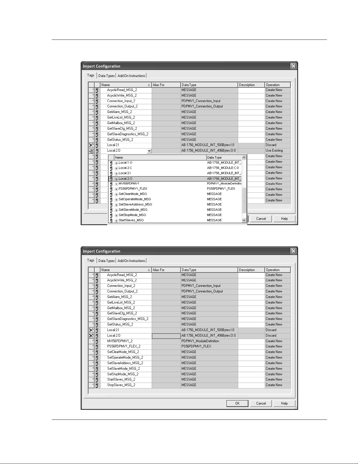
MVI56-PDPMV1 ♦ ControlLogix Platform Start Here
PROFIBUS DPV1 Master User Manual
Output Connection Variable
13 Click OK to confirm the import procedure.
ProSoft Technology, Inc. Page 61 of 255
March 22, 2011
Page 62

Start Here MVI56-PDPMV1 ♦ ControlLogix Platform
User Manual PROFIBUS DPV1 Master
14 The new rung will now be visible in the ladder logic.
15 The module name associated with the project uses a different name than the
standard "MVI56PDPMV1". You must re-define the path accordingly for each
MESSAGE tag associated to the Add-On Instruction. Click the symbol to
set up each MESSAGE tag. Select the Communication path as follows:
Page 62 of 255 ProSoft Technology, Inc.
March 22, 2011
Page 63

MVI56-PDPMV1 ♦ ControlLogix Platform Start Here
PROFIBUS DPV1 Master User Manual
16 Select the B
ROWSE
button and select the correct module to be associated to
the MESSAGE instruction. Click OK to confirm.
17 Click OK to confirm the MESSAGE configuration. Repeat this procedure for
every MESSAGE tag associated to the Add-On Instruction.
ProSoft Technology, Inc. Page 63 of 255
March 22, 2011
Page 64

Start Here MVI56-PDPMV1 ♦ ControlLogix Platform
User Manual PROFIBUS DPV1 Master
The setup procedure is now completed and the processor is ready to
communicate with the MVI56-PDPMV1 module.
Page 64 of 255 ProSoft Technology, Inc.
March 22, 2011
Page 65

MVI56-PDPMV1 ♦ ControlLogix Platform Start Here
PROFIBUS DPV1 Master User Manual
1.8 Common Settings for All Sample Programs
Certain parameter options are common to all the various versions of ladder logic
and Add-On Instruction sample programs. Specific settings for these parameters
vary based on which sample is used and the details of your specific custom
application.
1.8.1 Choosing the Controller Type
This sample application shows a 1756-L63 ControlLogix 5563 Controller
selected. If you are using a different model of the ControlLogix processor, you
must configure the sample program to use the correct processor model.
To change the controller type
1 In RSLogix 5000, once you have loaded a sample program or started a new
project, right-click the Controller <Name> folder at the top of the Controller
Organizer pane to open a shortcut menu; or you may left-click the Processor
icon in the Online Toolbar .
ProSoft Technology, Inc. Page 65 of 255
March 22, 2011
Page 66

Start Here MVI56-PDPMV1 ♦ ControlLogix Platform
User Manual PROFIBUS DPV1 Master
2 On the shortcut menu, choose P
ROPERTIES
. This action opens the Controller
Properties dialog box.
Page 66 of 255 ProSoft Technology, Inc.
March 22, 2011
Page 67

MVI56-PDPMV1 ♦ ControlLogix Platform Start Here
PROFIBUS DPV1 Master User Manual
3 Click the C
HANGE CONTROLLER
button. This action opens the Change
Controller dialog box.
4 Open the T
YPE
drop-down list, and then select your ControlLogix controller.
5 Select the correct firmware revision for your controller.
6 Click OK to save your changes and return to the previous window.
7 Select the chassis type that matches your specific installation.
ProSoft Technology, Inc. Page 67 of 255
March 22, 2011
Page 68

Start Here MVI56-PDPMV1 ♦ ControlLogix Platform
User Manual PROFIBUS DPV1 Master
1.8.2 Selecting the Slot Number for the Module
This sample application is for a module installed in Slot 1 in a ControlLogix rack.
The ladder logic uses the slot number to identify the module. If you are installing
the module in a different slot, you must update the ladder logic so that program
tags and variables are correct, and do not conflict with other modules in the rack.
To change the slot number
1 In the Controller Organization list, select the module and then click the right
mouse button to open a shortcut menu.
2 On the shortcut menu, choose P
Properties dialog box.
ROPERTIES
. This action opens the Module
3 In the Slot field, use the spinners on the right side of the field to select the slot
number where the module will reside in the rack, and then click OK.
RSLogix will automatically apply the slot number change to all tags, variables
and ladder logic rungs that use the MVI56-PDPMV1 slot number for computation.
Page 68 of 255 ProSoft Technology, Inc.
March 22, 2011
Page 69

MVI56-PDPMV1 ♦ ControlLogix Platform Start Here
PROFIBUS DPV1 Master User Manual
1.8.3 Selecting the Connection Parameters for the Module
The connection parameters will determine the number of words each backplane
I/O block will contain for data transfer between the processor and the module.
The input and output backplane block sizes will depend on the MVI56-PDPMV1
version and the selected mode (LEGACY or FLEX). Depending on these factors,
the connection parameters may be set as Fixed or Flexible lengths.
While following the procedures in the appropriate sections, keep in mind to set
the Use Legacy Mode parameter to match the sample program version
(LEGACY or FLEX) that you selected and loaded. If you get a mismatch between
this parameter setting and the sample ladder program loaded, the module will not
function.
The following settings are configured in ProSoft Configuration Builder for
modules with firmware version 1.21 or later only. Note that the parameters that
are displayed on the Edit screen vary depending on whether YES or NO is
selected for the Use Legacy Mode parameter. For more information, refer to
Setting Module Parameters (page 82).
Select LEGACY mode (U
SE LEGACY MODE =
Y)
ProSoft Technology, Inc. Page 69 of 255
March 22, 2011
Page 70

Start Here MVI56-PDPMV1 ♦ ControlLogix Platform
User Manual PROFIBUS DPV1 Master
Select FLEX mode (U
SE LEGACY MODE
= N)
Set Module Properties in RSLogix 5000 According to Mode Selected
For additional details about setting connection parameters for FLEX mode, see
Adjust the Connection Sizes for Your Application (page 41).
Page 70 of 255 ProSoft Technology, Inc.
March 22, 2011
Page 71

MVI56-PDPMV1 ♦ ControlLogix Platform Start Here
PROFIBUS DPV1 Master User Manual
1.8.4 Selecting the RPI Time for the Module
Refer to the Connection tab and enter the RPI time. The connection is scheduled
to move data to or from the module at least this often.
The RPI time to enter depends on your application as follows:
RPI Time 5 to 750 milliseconds
For ANY of the following conditions
MVI56-PDPMV1 module firmware version 0.30
MVI56-PDPMV1 module firmware version 1.21 (or later) AND configured in
LEGACY mode (U
MVI56-PDPMV1 module firmware version 1.21 (or later) AND configured in
FLEX mode (U
remote rack through ControlNet
Enter the RPI time that will provide optimum backplane performance for your
application, within the range from 5
SE LEGACY MODE = YES
SE LEGACY MODE
= NO) AND MVI56-PDPMV1 is located in a
MS
to 750
)
MS
.
ProSoft Technology, Inc. Page 71 of 255
March 22, 2011
Page 72

Start Here MVI56-PDPMV1 ♦ ControlLogix Platform
User Manual PROFIBUS DPV1 Master
RPI Time 750 milliseconds
If ALL of the following conditions are true:
MVI56-PDPMV1 module firmware version 1.21 (or later)
MVI56-PDPMV1 module configured in FLEX mode (U
SE LEGACY MODE = NO
)
MVI56-PDPMV1 module is located in either the local rack or remote rack
through EtherNet/IP adapters
For optimal performance set the RPI time as 750
MS
. For this scenario, the
module will use the IOT (Immediate Output) instruction that will override the
configured RPI time. Setting a lower RPI time will cause unnecessary interrupts
to the module, delaying data updates and lowering data throughput.
1.8.5 Changing and Importing Configuration Changes (for PCB v
2.2.0 and up only)
NOTE: This procedure must be used anytime you wish to change the module configuration after
the first time an AOI rung import was performed. For changes to be effective, previous controller
tags and ladder logic must be manually deleted before the new rung export file can be successfully
imported. Failure to follow this procedure may result in the module becoming non-functional.
This procedure assumes you have already made your configuration changes and
have re-exported the processor files according the procedure specified in Export
the Processor Files for PCB v2.2.0 or later (page 107).
To successfully complete this update procedure, you must do the following steps
in the order shown:
Page 72 of 255 ProSoft Technology, Inc.
March 22, 2011
Page 73

MVI56-PDPMV1 ♦ ControlLogix Platform Start Here
PROFIBUS DPV1 Master User Manual
1 D
ELETE
the existing ladder logic rung that contains the previously imported
Add-On Instruction (AOI) ladder file.
2 Go to the Controller Tags window and select the E
the controller tags associated with the AOI import.
DIT TAGS
tab. D
ELETE
all
ProSoft Technology, Inc. Page 73 of 255
March 22, 2011
Page 74

Start Here MVI56-PDPMV1 ♦ ControlLogix Platform
User Manual PROFIBUS DPV1 Master
3 Go to the Add-On Instructions folder in the project tree. D
ELETE
the
"AOI56PDPMV1_FLEX" AOI that was created by the original import.
4 Go to the Data Types folder, to the User-Defined sub-folder. D
ELETE
the
following user-defined data types in the following order:
a) PDPMV1_Connection_Input
b) PDPMV1_Connection_Output
c) PDPMV1_PBInF
d) PDPMV1_PBOutF
e) PDPMV1_ModuleDefinition
f) PDPMV1_UTIL
g) PDPMV1_Configuration
h) PDPMV1_Backplane_IOSize
i) PDPMV1_PROFIBUS_IOSize
j) PDPMV1_Status
k) PDPMV1_StatusControl
l) PDPMV1_Module
Page 74 of 255 ProSoft Technology, Inc.
March 22, 2011
Page 75

MVI56-PDPMV1 ♦ ControlLogix Platform Start Here
PROFIBUS DPV1 Master User Manual
5 Go to the I/O Configuration folder. Locate the MVI56-PDPMV1 and right-click
on it to open a context menu, then left-click on P
Module Properties dialog box. Check and edit (if necessary) the I
O
UTPUT
Sizes in the Module Properties dialog box so that they match those
ROPERTIES
to open the
NPUT
and
you configured for the module in the ProSoft Configuration Builder (PCB) MVI
Profibus Master DPV1 edit window.
REMEMBER: It is also critically important that the I/O Configuration Module Name on the PCB
Edit box be set to match the Name parameter in the RSLogix5000 Module Properties box. The
name you enter in PCB is used to create a communication path for the Status and Acyclic Data
MSG instructions. If the two names are not identical, the import may appear to have completed
successfully; but the module will not work correctly because the MSG instructions will not have the
correct module name in the MSG instruction Communication tab Path parameter.
If you receive any warning messages from RSLogix 5000, during or after the import, about
duplicate data types being overwritten or not imported, you may safely ignore these messages.
The module will function correctly. You can eliminate any such warning messages by deleting all
UDTs before importing the new ladder rung file.
6 At this point, you are ready to import your new ladder rung file with your
configurations changes. Please return to the previous section and follow the
procedure found in the topic, Exporting the Processor Files for PCB v2.2.0 or
later (page 107).
ProSoft Technology, Inc. Page 75 of 255
March 22, 2011
Page 76

Start Here MVI56-PDPMV1 ♦ ControlLogix Platform
User Manual PROFIBUS DPV1 Master
1.9 Downloading the Sample Program to the Processor
To download the sample program from RSLogix 5000 to the ControlLogix
processor
Note: The key switch on the front of the ControlLogix module must be in the REM position. Be sure
you have saved a copy of the latest version of your RSLogix 5000 project file before you attempt a
download.
1 Connect to the processor using the best available method.
2 If you are not already online with the processor, open the C
menu, and then choose D
with the processor.
3 When communication is established, RSLogix will open a confirmation dialog
box. Click the D
OWNLOAD
processor.
OWNLOAD
. RSLogix will establish communication
button to transfer your application project to the
OMMUNICATIONS
4 RSLogix will compile the program and transfer it to the processor. This
process may take a few minutes.
5 When the download is complete, RSLogix will open another confirmation
dialog box. Click OK to switch the processor from Program mode to RUN
mode.
Note: If you receive an error message during these steps, refer to your RSLogix documentation to
interpret and correct the error.
6 To verify that the processor is communicating with the module, open the Main
Program folder in the Controller Organization pane in RSLogix, and double-
click MainRoutine. You will be able to see the numbers change in the
MVI56PDPMV1.Util.LastRead area in Rung 0 of the MainRoutine program.
Page 76 of 255 ProSoft Technology, Inc.
March 22, 2011
Page 77

MVI56-PDPMV1 ♦ ControlLogix Platform Start Here
PROFIBUS DPV1 Master User Manual
1.10 Connecting Your PC to the Module
With the module securely mounted, connect your PC to the Configuration/Debug
port using the RJ45-DB-9 Serial Adapter Cable and the Null Modem Cable
included in the package with the MVI56-PDPMV1 module.
1 Connect the RJ45-DB-9 Serial Adapter Cable to the Null Modem Cable.
2 Insert the RJ45 cable connector from the RJ45-DB-9 cable into the
Configuration/Debug port of the module.
3 Attach the other end to the serial port on your PC.
ProSoft Technology, Inc. Page 77 of 255
March 22, 2011
Page 78

Start Here MVI56-PDPMV1 ♦ ControlLogix Platform
User Manual PROFIBUS DPV1 Master
Page 78 of 255 ProSoft Technology, Inc.
March 22, 2011
Page 79

MVI56-PDPMV1 ♦ ControlLogix Platform Configuring the MVI56-PDPMV1 Module
PROFIBUS DPV1 Master User Manual
2 Configuring the MVI56-PDPMV1 Module
In This Chapter
Setting Up the Project ........................................................................... 80
Setting Module Parameters ................................................................... 82
Configuring the PROFIBUS Master ....................................................... 84
Downloading the Project to the Module ............................................... 111
Verifying Correct Operation ................................................................. 123
Because the task of configuring the PROFIBUS network can be challenging,
ProSoft Technology has provided a configuration tool called ProSoft
Configuration Builder (PCB) that will help you with the following tasks:
Creating a configuration project (page 80)
Setting module parameters (page 82)
Configuring the PROFIBUS network (page 84) (Master and slaves)
Downloading the project to the module (page 111)
The following topics of this chapter explain each task step-by-step.
ProSoft Technology, Inc. Page 79 of 255
March 22, 2011
Page 80

Configuring the MVI56-PDPMV1 Module MVI56-PDPMV1 ♦ ControlLogix Platform
User Manual PROFIBUS DPV1 Master
2.1 Setting Up the Project
To begin, start ProSoft Configuration Builder (PCB). If you have used other
Windows configuration tools before, you will find the screen layout familiar.
ProSoft Configuration Builder’s window consists of a tree view on the left, and an
information pane and configuration pane on the right side of the window. When
you first start PCB, the tree view consists of folders for Default Project and
Default Location, with a Default Module in the Default Location folder. The
following illustration shows the PCB window with a new project.
Start configuring the module by adding the MVI56-PDPMV1 module to the
project.
1 Use the mouse to select D
EFAULT MODULE
in the tree view, and then click the
right mouse button to open a shortcut menu.
Page 80 of 255 ProSoft Technology, Inc.
March 22, 2011
Page 81

MVI56-PDPMV1 ♦ ControlLogix Platform Configuring the MVI56-PDPMV1 Module
PROFIBUS DPV1 Master User Manual
2 On the shortcut menu, choose C
HOOSE MODULE TYPE
. This action opens the
Choose Module Type dialog box.
3 In the Product Line Filter area of the dialog box, select MVI56. In the Select
Module Type dropdown list, select MVI56-PDPMV1, and then click OK to
save your settings and return to the main PCB window.
ProSoft Technology, Inc. Page 81 of 255
March 22, 2011
Page 82

Configuring the MVI56-PDPMV1 Module MVI56-PDPMV1 ♦ ControlLogix Platform
User Manual PROFIBUS DPV1 Master
2.2 Setting Module Parameters
Notice that the contents of the information pane and the configuration pane
changed when you added the MVI56-PDPMV1 module to the project. The red
"X" icon indicates that the module’s configuration is incomplete.
In the following steps, you will provide the missing information to make the red
"X"s go away.
1 Click the plus sign [+] next to the module to expand the module tree, and
then expand the MVI PDPM-V1 tree.
2 Double-click the MVI56 PROFIBUS M
ASTER
object. This action opens the
Edit dialog box.
3 In the Edit dialog box, configure the values for I
D
ATA SIZE
(PROFIBUS input and output words) to match the values required
NPUT DATA SIZE
and O
UTPUT
by your application. To change a value, select the parameter to modify in the
left pane, and then type the new value in the edit field in the right pane.
Page 82 of 255 ProSoft Technology, Inc.
March 22, 2011
Page 83
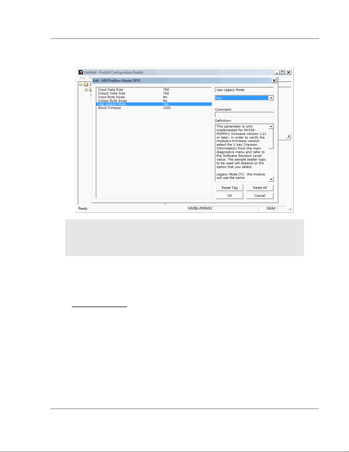
MVI56-PDPMV1 ♦ ControlLogix Platform Configuring the MVI56-PDPMV1 Module
PROFIBUS DPV1 Master User Manual
For the sample application, the input and output data size values should both
be 768.
Note: Select the module mode (FLEX or LEGACY) to match the sample program previously
selected as follows:
If you chose a FLEX sample: Set U
If you chose a LEGACY sample: Set U
SE LEGACY MODE
SE LEGACY MODE
= NO
= YES
4 Click OK to save your settings and return to the main PCB window.
At this time, you may wish to rename the D
L
OCATION
folders in the tree view.
EFAULT PROJECT
and D
EFAULT
To rename an object
1 Select the object, and then click the right mouse button to open a shortcut
menu. From the shortcut menu, choose R
ENAME
.
2 Type the name to assign to the object.
3 Click away from the object to save the new name.
ProSoft Technology, Inc. Page 83 of 255
March 22, 2011
Page 84

Configuring the MVI56-PDPMV1 Module MVI56-PDPMV1 ♦ ControlLogix Platform
User Manual PROFIBUS DPV1 Master
2.3 Configuring the PROFIBUS Master
In this task, you will configure the PROFIBUS Master, and then add PROFIBUS
slaves to the PROFIBUS network. When this step is complete, you will download
the configuration information to the MVI56 module. You will also export the I/O
maps for the processor.
1 In PCB tree view, click [+] to expand the MVI56-PDPMV1 tree, and then
double-click the PROFIBUS DP icon. This action opens the PDPMV1
PROFIBUS Master Setup dialog box.
2 In the PDPMV1 PROFIBUS Master Setup dialog box, click the C
PROFIBUS button. This action opens the ProSoft Configuration Builder for
PROFIBUS application.
3 Click [+] to expand the PROFIBUS Master tree.
4 Drag the PROFIBUS Master icon into the Bus Configuration window. This is
automatically done by the software for new applications.
ONFIGURE
5 Double-click the PROFIBUS M
ASTER
icon in the Bus Configuration window.
This action opens the Master Properties dialog box.
6 On the Common tab, name your PROFIBUS drop.
Note: The PROFIBUS tab contains the address setting and advanced configuration settings for the
Master. The default settings on this tab work best in most applications.
7 Click OK to save your changes and return to the Bus Configuration window.
Page 84 of 255 ProSoft Technology, Inc.
March 22, 2011
Page 85

MVI56-PDPMV1 ♦ ControlLogix Platform Configuring the MVI56-PDPMV1 Module
PROFIBUS DPV1 Master User Manual
2.3.1 Installing the GSD Files
ProSoft Configuration Builder (PCB) uses PROFIBUS slave device definition files
(GSD files) to obtain basic configuration information about the PROFIBUS slaves
you add to the network. The GSD configuration files identify the slave’s
capabilities so that the MVI56-PDPMV1 can communicate with it correctly. Slave
device manufacturers provide the GSD files for the equipment they make. Slave
device files sometimes come in various languages. When a manufacturer
provides slave device files in several languages, it is a common practice to use
the third letter of the file extension to indicate the language used in the file. For
instance:
o
.GSD is the most commonly used file extension and will usually be in
either English or German
o
.GSE will usually be in English
o
.GSS will usually be in Spanish
o
.GSF will usually be in French
o
other combinations may also be seen, as well as other languages using
the letters indicated above
Follow these steps to install the GSD file or files for your slave device or devices.
Tip: GSD configuration files for popular PROFIBUS slaves and ProSoft Technology solutions are
included with PCB. Before installing GSD files, browse the list of available slaves in the Tree View
window to see if GSD files for your slave are already installed.
GSD files are often both model number specific as well as model revision specific. Just because
you may have an older GSD file from a manufacturer for the particular make and model of your
slave device does not guarantee it will work for a newer revision of that device. Be sure you obtain
from the device manufacturer the correct GSD file or files for your PROFIBUS slave or slaves.
ProSoft Technology, Inc. Page 85 of 255
March 22, 2011
Page 86

Configuring the MVI56-PDPMV1 Module MVI56-PDPMV1 ♦ ControlLogix Platform
User Manual PROFIBUS DPV1 Master
To install GSD files manually
1 In ProSoft Configuration Builder tree view, click [+] to expand the module
tree, and then double-click the PROFIBUS DP icon. This action opens the
PDPMV1 PROFIBUS Master Setup dialog box.
2 Click the C
ONFIGURE
PROFIBUS button. This action opens the ProSoft
Configuration Builder for PROFIBUS application.
3 Open the T
OOLS
menu, and then choose I
NSTALL NEW
GS*
FILE
. This action
opens a dialog box that allows you to browse for the location of the GSD
configuration files to install. (Depending on the device and language used in
the file, the actual extension may be ".GSD", ".GSE", ".GSS", or other
combinations; hence the generic reference to ".GS*" files, where "*" is a
wildcard that stands for any letter.)
4 Choose the file to install, and then click O
PEN
. If the file already exists in the
configuration file path, you will be prompted to overwrite the file.
5 You will be prompted to associate the GSD configuration file with a bitmap
image of the slave device. Use the F
ILE / OPEN
dialog box to browse for the
location of the image file to use. If you have no device-specific bitmap file,
you may C
the Bus Configuration window for this slave device.
ANCEL
the bitmap upload, and a generic device icon will be used in
2.3.2 Configuring the PROFIBUS Slaves
There are two essential steps to configuring a slave:
1 Add the slave in ProSoft Configuration Builder (PCB) as a device connected
to the PROFIBUS Master, specifying the slave address and any necessary
input and output configuration. Download the PROFIBUS Master
configuration to the MVI56-PDPMV1 module.
2 Configure the slave (using PCB or the configuration tool supplied by the
manufacturer, for some PROFIBUS slaves). Verify that the slave address
configured in the slave module matches the slave address configured in PCB.
Download the PROFIBUS Slave configuration to the slave module.
Page 86 of 255 ProSoft Technology, Inc.
March 22, 2011
Page 87

MVI56-PDPMV1 ♦ ControlLogix Platform Configuring the MVI56-PDPMV1 Module
PROFIBUS DPV1 Master User Manual
Scanning for Slaves Manually
The following steps describe how to add and configure a Siemens EM 277 PLC
as a slave module. The configuration information (.GSD file) for this module is
already installed with ProSoft Configuration Builder.
1 In ProSoft Configuration Builder for PROFIBUS, click the plus sign [+] to
expand the PROFIBUS DP tree.
2 Navigate to the PLC/Siemens folder containing the EM 277 slave device to
add, and then click the plus sign [+] to expand the folder.
ProSoft Technology, Inc. Page 87 of 255
March 22, 2011
Page 88

Configuring the MVI56-PDPMV1 Module MVI56-PDPMV1 ♦ ControlLogix Platform
User Manual PROFIBUS DPV1 Master
3 Drag the slave icon into the Bus Configuration window. This action adds the
slave device and connects it to the Master in a network relationship.
Page 88 of 255 ProSoft Technology, Inc.
March 22, 2011
Page 89

MVI56-PDPMV1 ♦ ControlLogix Platform Configuring the MVI56-PDPMV1 Module
PROFIBUS DPV1 Master User Manual
4 In the tree view, click the plus sign [+] to expand the slave device you added.
This action opens a list of device configuration values. The following
illustration shows the possible input/output configuration values for a Siemens
EM 277 PLC Slave. The selections available for other devices will be
different, so you should review the specifications for the product you are
installing in order to determine the correct values to use.
5 Drag the input and output parameters to the Slot Location Grid (Subscriber
List) below the Bus Configuration window. This view displays the slot number,
configuration data, and starting input and output addresses. The MVI56PDPMV1 Master uses this information to identify and communicate with
individual slaves on the network.
ProSoft Technology, Inc. Page 89 of 255
March 22, 2011
Page 90

Configuring the MVI56-PDPMV1 Module MVI56-PDPMV1 ♦ ControlLogix Platform
User Manual PROFIBUS DPV1 Master
For this example, we will configure thirty-two (32) words of output and eight
(8) words of input. These input and output words are assigned to addresses
within the MVI56-PDPMV1 module's internal database.
For each new slave added to the PROFIBUS network, PCB automatically
converts the input/output byte addresses to word input/output addresses for
the tag database in the processor.
Tip: To make it easier to view the data from individual slaves, give each slave a meaningful name,
and place each slave's I/O areas in contiguous blocks. Use the Processor Network Memory Map
(page 104) as an aid to cross-referencing the slave I/O data in RSLogix 5000.
Page 90 of 255 ProSoft Technology, Inc.
March 22, 2011
Page 91

MVI56-PDPMV1 ♦ ControlLogix Platform Configuring the MVI56-PDPMV1 Module
PROFIBUS DPV1 Master User Manual
6 Double-click the S
LAVE
icon to view the Slave Properties.
PCB automatically assigns a PROFIBUS address to each new slave. The
address assignment begins at address 3, and is incremented by 1 for each
new slave added to the network. You can change the address in the
Common tab of the Slave Properties dialog box. PCB will not allow you to
assign a PROFIBUS address that is already in use by another device on this
network.
Leave the remaining settings unchanged for now, and click OK to close the
Slave Properties dialog box.
7 Repeat steps 2 through 6 for all slaves you intend to place on the network.
8 When you are finished adding slaves, open the P
E
XIT
. Click YES to save the project and return to the PROFIBUS Master
Setup dialog box.
ROJECT
menu and choose
ProSoft Technology, Inc. Page 91 of 255
March 22, 2011
Page 92

Configuring the MVI56-PDPMV1 Module MVI56-PDPMV1 ♦ ControlLogix Platform
User Manual PROFIBUS DPV1 Master
Using The Autoscan Feature
The concept of Automatic network scanning means that the user can instruct the
Bus Configuration window to automatically gather information about slaves that
are connected to the network. When the scan is completed the user can adopt
the detected slaves to the bus configuration and download to the Master.
This is a quick way to get a network up and running. However, one should be
aware that it is not guaranteed that any particular slave will enter data exchange
since the user parameter data might not match. This is especially obvious if no
associated GSD-file is found during the network scan, this means that no user
parameter data would be sent to the slave.
N
ETWORK SCAN
down menu for the M
is selectable from the Online menu as well as from the drop-
ASTER
icon.
Page 92 of 255 ProSoft Technology, Inc.
March 22, 2011
Page 93

MVI56-PDPMV1 ♦ ControlLogix Platform Configuring the MVI56-PDPMV1 Module
PROFIBUS DPV1 Master User Manual
When the download is completed, the PROFIBUS Master Configuration window
will initialize the Master to operate as a Class 2 Master only. In this mode it is
possible to initialize the Master even if the database does not contain any slaves.
After successful initialization, the PROFIBUS Master Configuration window will
issue the following mailboxes in order to gather information about the connected
slaves:
1 1. Send FB_APPL_GET_LIVE_LIST in order to detect connected slaves,
2 2. Send FB_APPL_GET_SLAVE_DIAG (external request) to all devices
identified as slaves according to the Live list.
3 3. Send FB_APPL_GET_SLAVE_CONFIG to all devices identified as slaves
according to the Live list.
ProSoft Technology, Inc. Page 93 of 255
March 22, 2011
Page 94

Configuring the MVI56-PDPMV1 Module MVI56-PDPMV1 ♦ ControlLogix Platform
User Manual PROFIBUS DPV1 Master
When the information is collected the PROFIBUS Master Configuration window
will find a matching GSD-file and extract information from it. Refer to the
flowchart below for this sequence:
Page 94 of 255 ProSoft Technology, Inc.
March 22, 2011
Page 95

MVI56-PDPMV1 ♦ ControlLogix Platform Configuring the MVI56-PDPMV1 Module
PROFIBUS DPV1 Master User Manual
GSD Selection Algorithm
If two or more matching GSD-files are found, the first one found should be
selected. The other compatible files should be stored so that the user can select
one of them instead. If the user selects another GSD-file, the PROFIBUS Master
Configuration window will run through the Module Selection Algorithm (described
below) again.
Module Selection Algorithm
The algorithm used to find modules in the GSD based on the Identifier byte(s) is
as follows:
Select the module that matches the largest number of Identifier bytes. If the GSD
contains two or more modules with the exact set of Identifier bytes, use the first
module found.
Example:
If a slave responds with identifier bytes: 0x11, 0x21, 0x31 and that the associated
GSD-file contains five modules: “A” = 0x11, “B” = 0x21, “C” = 0x31, “AB” = 0x11,
0x21 and “BC” = 0x21, 0x31. The PROFIBUS Master Configuration window will
then select modules "AB" and "C".
Note: If no matching module is found in the GSD, The PROFIBUS Master Configuration window
will display the identifier byte(s) instead.
Network scan window
The information extracted from the GSD-file(s) will be displayed in the Network
scan window.
Select
In this column all found slaves will be marked as selected by default, except for
slaves with the special address 126 (refer to the next section that describes the
Address column). Only selected slaves will be added to the PROFIBUS Master
Configuration when the A
DOPT SELECTED SLAVES
button is clicked.
Address
In this column the node address of the slaves will be displayed. Found slaves
should be listed in ascending order according to their node addresses.
ProSoft Technology, Inc. Page 95 of 255
March 22, 2011
Page 96

Configuring the MVI56-PDPMV1 Module MVI56-PDPMV1 ♦ ControlLogix Platform
User Manual PROFIBUS DPV1 Master
Special address 126 -Set Slave address:
If a slave with node address 126 is detected during the network scan, the
PROFIBUS Master Configuration window will display the address in red color. It
will not be possible for the user to adopt the slave to the configuration since it is
not allowed to exchange data with devices having this address. The check box in
the Select column will be grayed out.
To be able to adopt a slave with address 126 the user must first assign a valid
address by clicking the icon next to the node address. By doing so the Set Slave
Address dialog box is started.
Note that the Old slave address is preset to a value of 126 that is not editable (grayed out).
Page 96 of 255 ProSoft Technology, Inc.
March 22, 2011
Page 97

MVI56-PDPMV1 ♦ ControlLogix Platform Configuring the MVI56-PDPMV1 Module
PROFIBUS DPV1 Master User Manual
If the Slave is in the configuration already then it will not affect the addressing.
Example:
After scanning, the network finds these other slaves: 2, 6, 25, and 40
Slaves 2, 6, and 25 are found, but are marked as in the bus configuration (the
mapping of the inputs and outputs will not be affected)
Slaves 40 is new and could be added and the input/output addressing will be
appended to the end as shown on the last screen.
ProSoft Technology, Inc. Page 97 of 255
March 22, 2011
Page 98

Configuring the MVI56-PDPMV1 Module MVI56-PDPMV1 ♦ ControlLogix Platform
User Manual PROFIBUS DPV1 Master
The PROFIBUS Master Configuration window will prevent the user from selecting
a New slave address that is already occupied by another device; this includes
detected Master stations as well. If the user selects an occupied address, a
message similar to the one shown here will open.
When an address has been successfully assigned, the PROFIBUS Master
Configuration window will update the Network scan window as shown here. The
node address will be updated to the one that the user selected in the Set Slave
dialog box. The check box in the Select column will be marked allowing the user
to adopt the slave to the configuration.
Page 98 of 255 ProSoft Technology, Inc.
March 22, 2011
Page 99
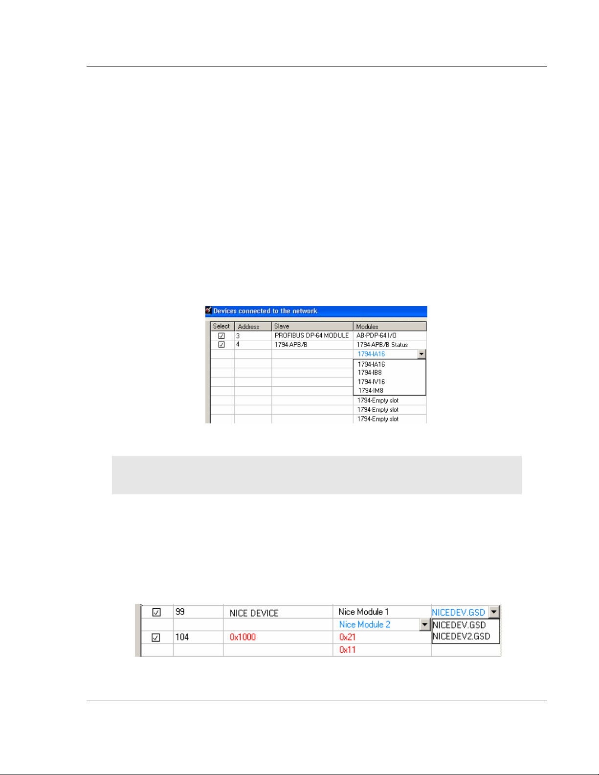
MVI56-PDPMV1 ♦ ControlLogix Platform Configuring the MVI56-PDPMV1 Module
PROFIBUS DPV1 Master User Manual
Slave
In this column the name of the slave as stated in the assigned GSD-file will be
displayed. If no matching GSD-file is found the Ident number will be displayed in
red color in the drop-down list.
Module
This column shows the name of the module(s) as stated in the assigned GSD-
file, which matches the Identifier byte(s) derived from the GetCfg mailbox
message. If no GSD-file or no matching module is found the Identifier byte(s) will
be displayed in red color. If the configuration for a slave is constructed of several
modules, the modules will be listed under each other.
If there is more than one module in the GSD-file that matches the Identifer bytes,
the first matching module will be displayed in blue color in a drop-down list. The
drop-down list will contain all other matching modules so that the user can select
the desired one.
Note: Only modules that have the exact same Identifer bytes as the first matching module will be
displayed in the drop-down list
GSD-file
This column shows the name of the GSD-file that matches the Ident number
derived from the SlaveDiag mailbox message. If there are more files with the
same Ident number in the device catalog, the first matching GSD-file will be
displayed in blue color in a drop-down list.
ProSoft Technology, Inc. Page 99 of 255
March 22, 2011
Page 100

Configuring the MVI56-PDPMV1 Module MVI56-PDPMV1 ♦ ControlLogix Platform
User Manual PROFIBUS DPV1 Master
This could be the case if the device catalog contains two or more brand labeled
devices, or GSD-files for two or more languages (for example NICEDEV.GSD
and NICEDEV.GSE) exist.
Note: If the user selects another GSD-file, The PROFIBUS Master Configuration window will
update the modules for that slave accordingly.
If no GSD-file is found the user will be able to copy the expected GSD to the
device catalog by clicking the icon next to the text No GSD found. This will start
the Install new GS*-file dialog box. When the file is installed, the PROFIBUS
Master Configuration window will verify that the installed file matches the slave
and update the modules for the slave accordingly.
Rescan
Pressing the Y
ES
button will trigger a new network scan. Before proceeding with
the scan a message similar to the one below will appear. If a new scan is
accepted, detected slaves found during the previous scan will be lost.
Note: The autoscan function cannot delete slaves in the current configuration, it can only change (if
slaves differs) or add. The slave must be manually removed from the bus configuration in order to
be able to add it again via the scan window.
Page 100 of 255 ProSoft Technology, Inc.
March 22, 2011
 Loading...