

Page 1
MVI56-LTQ
ControlLogix Platform
Limitorque Valve Actuator Master
Communication Module
August 30, 2010
USER MANUAL
Page 2

Your Feedback Please
We always want you to feel that you made the right decision to use our products. If you have suggestions, comments,
compliments or complaints about our products, documentation, or support, please write or call us.
ProSoft Technology
5201 Truxtun Ave., 3rd Floor
Bakersfield, CA 93309
+1 (661) 716-5100
+1 (661) 716-5101 (Fax)
www.prosoft-technology.com
support@prosoft-technology.com
Copyright © 2010 ProSoft Technology, Inc., all rights reserved.
MVI56-LTQ User Manual
August 30, 2010
®
ProSoft Technology
, ProLinx ®, inRAx ®, ProTalk®, and RadioLinx ® are Registered Trademarks of ProSoft
Technology, Inc. All other brand or product names are or may be trademarks of, and are used to identify products
and services of, their respective owners.
ProSoft Technology® Product Documentation
In an effort to conserve paper, ProSoft Technology no longer includes printed manuals with our product shipments.
User Manuals, Datasheets, Sample Ladder Files, and Configuration Files are provided on the enclosed CD-ROM,
and are available at no charge from our web site: www.prosoft-technology.com
Printed documentation is available for purchase. Contact ProSoft Technology for pricing and availability.
North America: +1.661.716.5100
Asia Pacific: +603.7724.2080
Europe, Middle East, Africa: +33 (0) 5.3436.87.20
Latin America: +1.281.298.9109
Page 3

Important Installation Instructions
Power, Input, and Output (I/O) wiring must be in accord anc e with Class I, Division 2 wiring methods, Article 501-4 (b)
of the National Electrical Code, NFPA 70 for installation in the U.S., or as specified in Section 18-1J2 of the Canadian
Electrical Code for installations in Canada, and in accordance with the authority having jurisdiction. The following
warnings must be heeded:
A WARNING - EXPLOSION HAZARD - SUBSTITUTION OF COMPONENTS MAY IMPAIR SUITABILITY FOR
CLASS I, DIV. 2;
B WARNING - EXPLOSION HAZARD - WHEN IN HAZARDOUS LOCATIONS, TURN OFF POWER BEFORE
REPLACING OR WIRING MODULES
C WARNING - EXPLOSION HAZARD - DO NOT DISCONNECT EQUIPMENT UNLESS POWER HAS BEEN
SWITCHED OFF OR THE AREA IS KNOWN TO BE NON-HAZARDOUS.
D THIS DEVICE SHALL BE POWERED BY CLASS 2 OUTPUTS ONLY.
MVI (Multi Vendor Interface) Modules
WARNING - EXPLOSION HAZARD - DO NOT DISCONNECT EQUIPMENT UNLESS POWER HAS BEEN
SWITCHED OFF OR THE AREA IS KNOWN TO BE NON-HAZARDOUS.
AVERTISSEMENT - RISQUE D'EXPLOSION - AVANT DE DÉCONNECTER L'ÉQUIPEMENT, COUPER LE
COURANT OU S'ASSURER QUE L'EMPLACEMENT EST DÉSI GNÉ NON DANGEREUX.
Warnings
North America Warnings
A Warning - Explosion Hazard - Substitution of components may impair suitability for Class I, Division 2.
B Warning - Explosion Hazard - When in hazardous locations, turn off power before replacing or rewiring modules.
Warning - Explosion Hazard - Do not disconnect equipment unless power has been switched off or the area is
known to be non-hazardous.
C Suitable for use in Class I, Division 2 Groups A, B, C and D Hazardous Locations or Non-Hazardous Locations.
ATEX Warnings and Conditions of Safe Usage:
Power, Input, and Output (I/O) wiring must be in accordance with the authority having jurisdiction.
A Warning - Explosion Hazard - When in hazardous locations, turn off power before replacing or wiring modules.
B Warning - Explosion Hazard - Do not disconnect equipment unless power has been switched off or the area is
known to be non-hazardous.
C These products are intended to be mounted in an IP54 enclosure. The devices shall provide external means to
prevent the rated voltage being exceeded by transient disturbances of more than 40%. This device must be used
only with ATEX certified backplanes.
D DO NOT OPEN WHEN ENERGIZED.
Electrical Ratings
Backplane Current Load: 800 mA @ 5.1 Vdc; 3 mA @ 24 Vdc
Operating Temperature: 0°C to 60°C (32°F to 140°F)
Storage Temperature: -40°C to 85°C (-40°F to 185°F)
Shock: 30 g operational; 50 g non-operational; Vibration: 5 g from 10 Hz to 150 Hz
Relative Humidity: 5% to 95% (without condensation)
All phase conductor sizes must be at least 1.3 mm(squared) and all earth ground conductors must be at least
4mm(squared).
Page 4

CSA/cUL
C22.2 No. 213-1987
CSA CB Certified
IEC61010
EN60079-0 Category 3, Zone 2
243333
ME06
Markings:
ATEX
EN60079-15
Battery Life Advisory
The MVI46, MVI56, MVI69, and MVI71 modules use a rechargeable Lithium Vanadium Pentoxide battery to backup
the real-time clock and CMOS. The battery should last for the life of the module. The module must be powered for
approximately twenty hours before the battery becomes fully charged. After it is fully charged, the battery provides
backup power for the CMOS setup and the real-time clock for approximately 21 days. When the battery is fully
discharged, the module will revert to the default BIOS and clock settings.
Note: The battery is not user replaceable.
Page 5

MVI56-LTQ ♦ ControlLogix Platform Contents
Limitorque Valve Actuator Master Communication Module User Manual
Contents
Your Feedback Please ........................................................................................................................ 2
ProSoft Technology® Product Documentation .................................................................................... 2
Important Installation Instructions ....................................................................................................... 3
MVI (Multi Vendor Interface) Modules ................................................................................................ 3
Warnings ............................................................................................................................................. 3
Battery Life Advisory ........................................................................................................................... 4
Guide to the MVI56-LTQ User Manual 9
1 Start Here 11
1.1 System Requirements ............................................................................................. 12
1.2 Package Contents ................................................................................................... 13
1.3 Setting Jumpers ...................................................................................................... 14
1.4 Installing the Module in the Rack ............................................................................ 15
1.5 Connecting Your PC to the ControlLo gix Pr oces s or ............................................... 16
1.6 Opening the Sample Ladder Logic .......................................................................... 17
1.6.1 Configuring the RSLinx Driver for the PC COM Port .............................................. 17
1.7 Downloading the Sample Program to the Processor .............................................. 19
1.8 Connect your PC to the Module .............................................................................. 20
2 Configuring the MVI56-LTQ Module 21
This chapter gives you a summary of all possible configuration parameters and their allowable
settings and ranges. For more detailed information on configuration and operation options, please
refer to the Reference chapter. ......................................................................................................... 21
2.1 Reference Documents ............................................................................................. 21
2.2 Configuration Object (LTQCfg) ............................................................................... 22
2.3 Configuration Data .................................................................................................. 23
2.3.1 BaudRate ................................................................................................................ 23
2.3.2 MsgRespTm ............................................................................................................ 23
2.3.3 MaxSlaves ............................................................................................................... 23
2.3.4 BTRMax................................................................................................................... 23
2.3.5 BlkDelay .................................................................................................................. 24
2.3.6 LastState ................................................................................................................. 24
2.3.7 NetPoll ..................................................................................................................... 24
2.3.8 PropDelay ................................................................................................................ 25
2.3.9 RTSOn..................................................................................................................... 25
2.3.10 SpecPolling ............................................................................................................. 26
2.3.11 Use_CTS ................................................................................................................. 26
2.3.12 BlkFailCnt ................................................................................................................ 26
2.3.13 ActiveSlaves ............................................................................................................ 27
3 Ladder Logic 29
3.1 Module Data Object (LTQModuleDef) ..................................................................... 30
3.1.1 Status Object (LTQStat) .......................................................................................... 31
3.1.2 User Data Objects ................................................................................................... 32
ProSoft Technology, Inc. Page 5 of 98
August 30, 2010
Page 6

Contents MVI56-LTQ ♦ ControlLogix Platform
User Manual Limitorque Valve Actuator Master Communication Module
3.2 Adding the Module to an Existing Project ............................................................... 34
4 Diagnostics and Troubleshooting 37
4.1 LED Status Indicators ............................................................................................. 38
4.1.1 Clearing a Fault Condition ...................................................................................... 39
4.1.2 Troubleshooting ...................................................................................................... 40
4.1.3 Communication Error Codes .................................................................................. 41
4.2 Using the Configuration/Debug Port ....................................................................... 42
4.3 Reading Status Data from the Module ................................................................... 43
4.3.1 Required Software .................................................................................................. 43
4.3.2 The Configuration/Debug Menu .............................................................................. 44
4.3.3 Main Menu .............................................................................................................. 45
4.3.4 Data Analyzer ......................................................................................................... 47
4.3.5 Data Analyzer Tips ................................................................................................. 49
4.3.6 Database View Menu .............................................................................................. 52
4.3.7 Valve Data Menu .................................................................................................... 54
5 Reference 55
5.1 Product Specifications ............................................................................................ 55
5.1.1 General Specifications ............................................................................................ 55
5.1.2 Hardware Specifications ......................................................................................... 56
5.1.3 Functional Specifications ........................................................................................ 57
5.2 Functional Overview ............................................................................................... 58
5.2.1 General Concepts ................................................................................................... 58
5.2.2 Data Flow Between MVI56-LTQ Module and ControlLogix Processor .................. 67
5.3 Cable Connections ................................................................................................. 68
5.3.1 RS-232 Configuration/Debug Port .......................................................................... 68
5.3.2 RS-232 Application Port(s) .................................................................................... 68
5.3.3 Network Cable Connection to Limitorque RS-232/RS-485 Converters .................. 71
5.3.4 RS-422 .................................................................................................................... 71
5.3.5 RS-485 Application Port(s) ..................................................................................... 72
5.3.6 DB9 to RJ45 Adaptor (Cable 14) ............................................................................ 72
5.4 MVI56-LTQ Database Definition ............................................................................. 74
5.5 MVI56-LTQ Status Data Definition ......................................................................... 76
5.6 LTQValve Object Definition .................................................................................... 77
5.7 Command Usage for Limitorque Products ............................................................. 80
5.8 Polling Schemes ..................................................................................................... 82
5.9 Typical Network Loop ............................................................................................. 85
6 Support, Service & Warranty 87
How to Contact Us: Technical Support ............................................................................................ 87
6.1 Return Material Authorization (RMA) Policies and Conditions ............................... 89
6.1.1 All Product Returns: ................................................................................................ 89
6.1.2 Procedures for Return of Units Under Warranty: .................................................... 90
6.1.3 Procedures for Return of Units Out of Warranty: .................................................... 90
6.2 LIMITED WARRANTY ............................................................................................ 91
6.2.1 What Is Covered By This Warranty ........................................................................ 91
6.2.2 What Is Not Covered By This Warranty .................................................................. 92
6.2.3 Disclaimer Regarding High Risk Activities .............................................................. 92
6.2.4 Intellectual Property Indemnity ............................................................................... 93
Page 6 of 98 ProSoft Technology, Inc.
August 30, 2010
Page 7

MVI56-LTQ ♦ ControlLogix Platform Contents
Limitorque Valve Actuator Master Communication Module User Manual
6.2.5 Disclaimer of all Other Warranties .......................................................................... 93
6.2.6 Limitation of Remedies ** ........................................................................................ 94
6.2.7 Time Limit for Bringing Suit ..................................................................................... 94
6.2.8 No Other Warranties ............................................................................................... 94
6.2.9 Allocation of Risks ................................................................................................... 94
6.2.10 Controlling Law and Severability ............................................................................. 95
Index 97
ProSoft Technology, Inc. Page 7 of 98
August 30, 2010
Page 8

Contents MVI56-LTQ ♦ ControlLogix Platform
User Manual Limitorque Valve Actuator Master Communication Module
Page 8 of 98 ProSoft Technology, Inc.
August 30, 2010
Page 9

MVI56-LTQ ♦ ControlLogix Platform Start Here
Details
system requirements, hardware installation, and
(page 58, page 53)
These sections contain general references
Index
This section contains Support, Service and
Limitorque Valve Actuator Master Communication Module User Manual
Guide to the MVI56-LTQ User Manual
Function
Introduction
(Must Do)
Diagnostic and
Troubleshooting
Reference
Product Specifications
Functional Overview
Support, Service, and
Warranty
Index
→
→
→
→
Section to Read
Start Here (page 11)
Diagnostics and
Troubleshooting
(page 37)
Reference (page 55)
Product
Specifications (page
55)
Functional Overview
Support, Service
and Warranty (page
87)
This section introduces the customer to the
module. Included are: package contents,
basic configuration.
This section describes Diagnostic and
Troubleshooting procedures.
associated with this product, Specifications, and
the Functional Overview.
Warranty information.
Index of chapters.
ProSoft Technology, Inc. Page 9 of 98
August 30, 2010
Page 10

Start Here MVI56-LTQ ♦ ControlLogix Platform
User Manual Limitorque Valve Actuator Master Communication Module
Page 10 of 98 ProSoft Technology, Inc.
August 30, 2010
Page 11

MVI56-LTQ ♦ ControlLogix Platform Start Here
Limitorque Valve Actuator Master Communication Module User Manual
1 Start Here
In This Chapter
System Requirements
Package Contents ................................................................................. 13
Setting Jumpers .................................................................................... 14
Installing the Module in the Rack ........................................................... 15
Connecting Your PC to the ControlLogix Processor .............................. 16
Opening the Sample Ladder Logic ........................................................ 17
Downloading the Sample Program to the Processor ............................. 19
Connect your PC to the Module ............................................................ 20
........................................................................... 12
To get the most benefit from this User Manual, you should hav e the following
skills:
Rockwell Automation
®
RSLogix™ software: launch the program, configure
ladder logic, and transfer the ladder logic to the processor
Microsoft Windows: install and launch programs, execute menu commands,
navigate dialog boxes, and enter data
Hardware installation and wiring: install the module, and safely connect
LTQ and ControlLogix devices to a power source and to the MVI56-LTQ
module’s application port(s)
Caution: You must be able to complete the application without exposing personnel or
equipment to unsafe or inappropriate working conditions.
ProSoft Technology, Inc. Page 11 of 98
August 30, 2010
Page 12

Start Here MVI56-LTQ ♦ ControlLogix Platform
User Manual Limitorque Valve Actuator Master Communication Module
1.1 System Requirements
The MVI56-LTQ module requires the following minimum hardware and software
components:
Rockwell Automation ControlLogix™ processor, with compatible power
supply and one free slot in the rack, for the MVI56-LTQ module. The module
requires 800 mA of available power.
Rockwell Automation RSLogix 5000 programming software version 2.51 or
higher
Rockwell Automation RSLinx communication software
Pentium
recommended
Supported operating systems:
o Microsoft Windows XP Professional with Service Pack 1 or 2
o Microsoft Windows 2000 Professional with Service P ack 1, 2, or 3
o Microsoft Windows Server 2003
128 Mbytes of RAM minimum, 256 Mbytes of RAM recommended
100 Mbytes of free hard disk space (or more based on application
requirements)
256-color VGA graphics adapter, 800 x 600 minimum resolution (True Color
1024 × 768 recommended)
CD-ROM drive
ProSoft Configuration Builder, HyperTerminal or other terminal emulator
program.
®
II 450 MHz minimum. Pentium III 733 MHz (or better)
Note: You can install the module in a local or remote rack. For remote rack installation, the module
requires EtherNet/IP or ControlNet communication with the processor.
Page 12 of 98 ProSoft Technology, Inc.
August 30, 2010
Page 13

MVI56-LTQ ♦ ControlLogix Platform Start Here
Qty.
Part Name
Part Number
Part Description
MVI56-LTQ Module
MVI56-LTQ
Limitorque Valve Actuator Master
Cable
Cable #15, RS232
Null Modem
For RS232 Connection to the CFG Port
Cable
Cable #14, RJ45 to
cable
For DB9 Connection to Module’s Port
ProSoft Solutions CD
Contains sample programs, utilitie s and
Limitorque Valve Actuator Master Communication Module User Manual
1.2 Package Contents
The following components are included with your MVI56-LTQ module, and are all
required for installation and configuration.
Important: Before beginning the installation, please verify that all of the following items are
present.
1
1
3
2
1
If any of these components are missing, please contact ProSoft Technology
Support for replacement parts.
Adapter 1454-9F Two Adapters, DB9 Female to Screw
Communication Module
DB9 Male Adapter
Terminal. For RS422 or RS485
Connections to Port 1 and 2 of the Module
documentation for the MVI56-LTQ module.
ProSoft Technology, Inc. Page 13 of 98
August 30, 2010
Page 14
Start Here MVI56-LTQ ♦ ControlLogix Platform
User Manual Limitorque Valve Actuator Master Communication Module
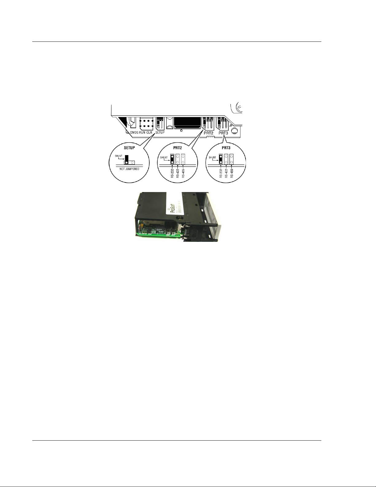
1.3 Setting Jumpers
If you use an interface other than RS-232 (default), you must change the jumper
configurati on to match the interface. There are three jumpers located at the
bottom of the module.
The following illustration shows the MVI56-LTQ jumper configuration:
1 Set the PRT 2 (for application port 1) and PRT 3 (for application port 2)
jumpers for RS232, RS422, or RS485 to match the wiring needed for your
application. The default jumper setting for both application ports is RS-232.
2 The Setup Jumper acts as "write protection" for the module’s flash memory.
In "write protected" mode, the Setup pins are not connected, and the
module’s firmware cannot be overwritten. Do not jumper the Setup pins
together unless you are directed to do so by ProSoft Technical Support.
Page 14 of 98 ProSoft Technology, Inc.
August 30, 2010
Page 15
MVI56-LTQ ♦ ControlLogix Platform Start Here
Limitorque Valve Actuator Master Communication Module User Manual
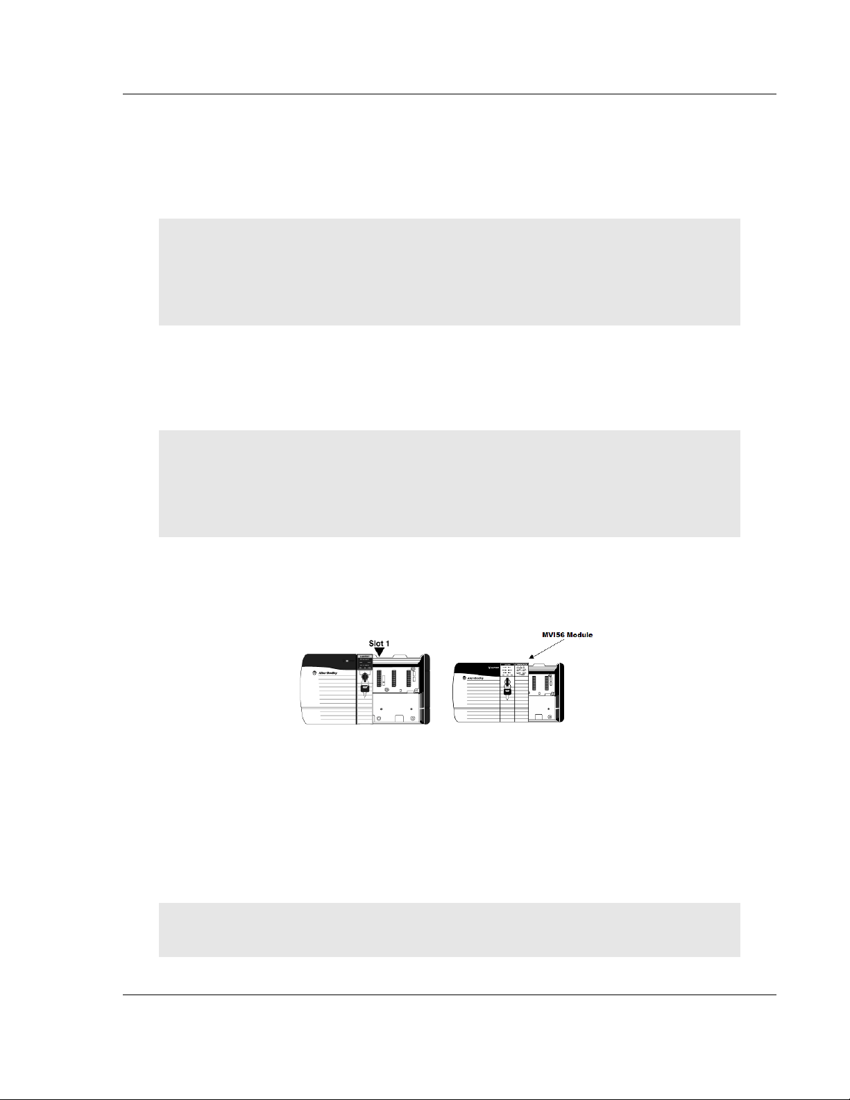
1.4 Installing the Module in the Rack
If you have not already installed and configured your ControlLogix processor and
power supply, please do so before installing the MVI56-LTQ module. Refer to
your Rockwell Automation product documentation for installation instructions.
Warning: You must follow all safety instructions when installing this or any other electronic
devices. Failure to follow safety procedures could result in damage to hardware or data, or even
serious injury or death to personnel. Refer to the documentation for each device you plan to
connect to verify that suitable safety procedures are in place before installing or servicing the
device.
After you have checked the placement of the jumpers, insert MVI56-LTQ into the
ControlLogix chassis. Use the same technique recommended by Rockwell
Automation to remove and install ControlLogix modules.
Warning: When you insert or remove the module while backplane power is on, an electrical arc
can occur. This could cause an explosion in hazardous location installations. Verify that power is
removed or the area is non-hazardous before proceeding. Repeated electrical arcing causes
excessive wear to contacts on both the module and its mating connector. Worn contacts may
create electrical resistance that can affect module operation.
1 Turn power OFF.
2 Align the module with the top and bottom guides, and slide it into the rack
until the module is firmly against the backplane connector.
3 With a firm but steady push, snap the module into place.
4 Check that the holding clips on the top and bottom of the module are securely
in the locking holes of the rack.
5 Make a note of the slot location. You must identify the slot in which the
module is installed in order for the sample program to work correctly. Slot
numbers are identified on the green circuit board (backplane) of the
ControlLogix rack.
6 Turn power ON.
Note: If you insert the module improperly, the system may stop working, or may behave
unpredictably.
ProSoft Technology, Inc. Page 15 of 98
August 30, 2010
Page 16
Start Here MVI56-LTQ ♦ ControlLogix Platform
User Manual Limitorque Valve Actuator Master Communication Module
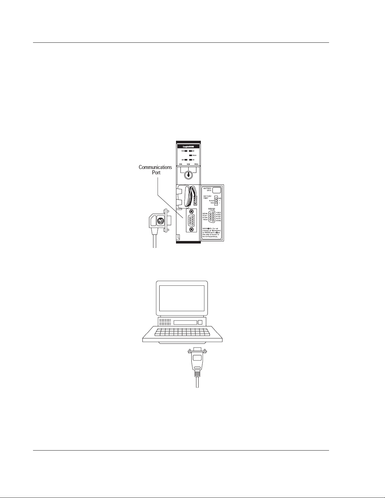
1.5 Connecting Your P C to the Control Logix Processor
There are several ways to establish communication between your PC and the
ControlLogix processor. The following steps show how to establish
communication through the serial interface. It is not mandatory that you use the
processor's serial interface. You may access the processor through whatever
network interface is available on your system. Refer to your Rockwell Automation
documentation for information on other connection methods.
1 Connect the right-angle connector end of the cable to your controller at the
communications port.
2 Connect the straight connector end of the cable to the serial port on your
computer.
Page 16 of 98 ProSoft Technology, Inc.
August 30, 2010
Page 17
MVI56-LTQ ♦ ControlLogix Platform Start Here
Limitorque Valve Actuator Master Communication Module User Manual
1.6 Opening the Sample Ladder Logic
The sample program for your MVI56-LTQ module includes custom tags, data
types and ladder logic for data I/O and status monitoring. For most applications,
you can run the sample ladder program without modification, or, for advanced
applications, you can incorporate the sample program into your existing
application.
The inRAx Solut io ns CD pr ovides one or more versions of the sample ladder
logic. The version number appended to the file name corresponds with the
firmware version number of your ControlLogix processor. The firmware version
and sample program version must match.
1.6.1 Configuring the RSLinx Driver for the PC COM Port
If RSLogix is unable to establish communication with the processor, follow these
steps.
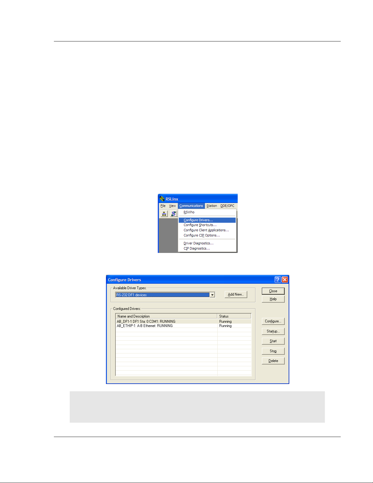
1 Open RSLinx.
2 Open the C
OMMUNICATIONS menu, and choose CONFIGURE DRIVERS.
This action opens the Configure Drivers dialog box.
Note: If the list of configured drivers is blank, you must first choose and configure a driver from the
Available Driver Types list. The recommended driver type to choose for serial communication with
the processor is RS-232 DF1 Devices.
ProSoft Technology, Inc. Page 17 of 98
August 30, 2010
Page 18
Start Here MVI56-LTQ ♦ ControlLogix Platform
User Manual Limitorque Valve Actuator Master Communication Module
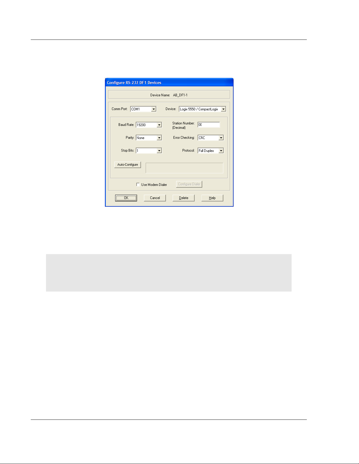
3 Click to select the driver, and then click C
ONFIGURE. This action opens the
Configure RS-232 DF1 Devices dialog box.
4 Click the A
UTO-CONFIGURE button. RSLinx will attempt to configure your
serial port to work with the selected driver.
5 When you see the message Auto Configuration Successful, click the OK
button to dismiss the dialog box.
Note: If the auto-configuration procedure fails, verify that the cables are connected correctly
between the processor and the serial port on your computer, and then try again. If you are still
unable to auto-configure the port, refer to your RSLinx documentation for further troubleshooting
steps.
Page 18 of 98 ProSoft Technology, Inc.
August 30, 2010
Page 19
MVI56-LTQ ♦ ControlLogix Platform Start Here
Limitorque Valve Actuator Master Communication Module User Manual
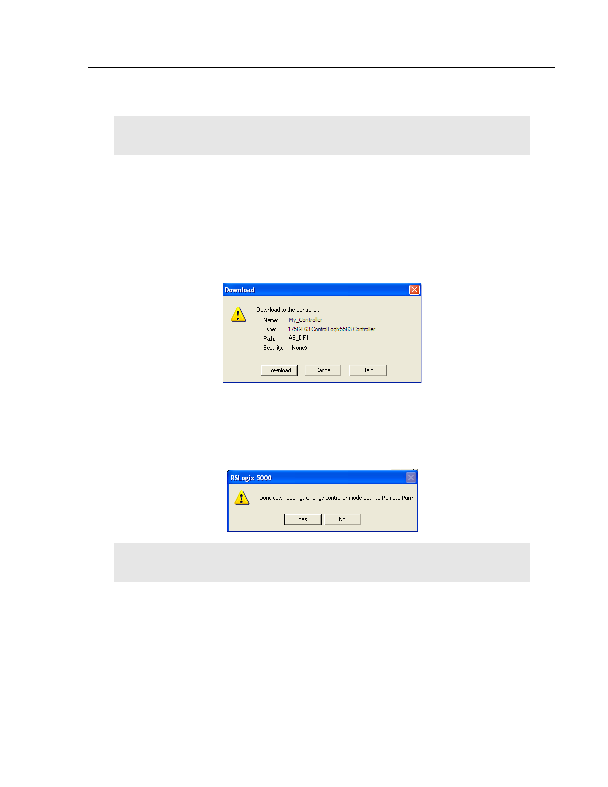
1.7 Downloading the Sample Program to the Processor
Note: The key switch on the front of the ControlLogix processor must be in the REM or PROG
position.
1 If you are not already online with the processor, open the Communications
menu, and then choose DOWNLOAD. RSLogix 5000 will establish
communication with the processor. You do not have to download through the
processor's serial port, as shown here. You may download through any
available network connection.
2 When communication is established, RSLogix 5000 will open a confirmation
dialog box. Click the D
processor.
OWNLOAD button to transfer the sample program to the
3 RSLogix 5000 will compile the program and transfer it to the processor. This
process may take a few minutes.
4 When the download is complete, RSLogix 5000 will open another
confirmation dialog box. If the key switch is in the REM position, click OK
switch the processor from PROGRAM
mode to RUN mode.
to
Note: If you receive an error message during these steps, refer to your RSLogix documentation to
interpret and correct the error.
ProSoft Technology, Inc. Page 19 of 98
August 30, 2010
Page 20
Start Here MVI56-LTQ ♦ ControlLogix Platform
User Manual Limitorque Valve Actuator Master Communication Module
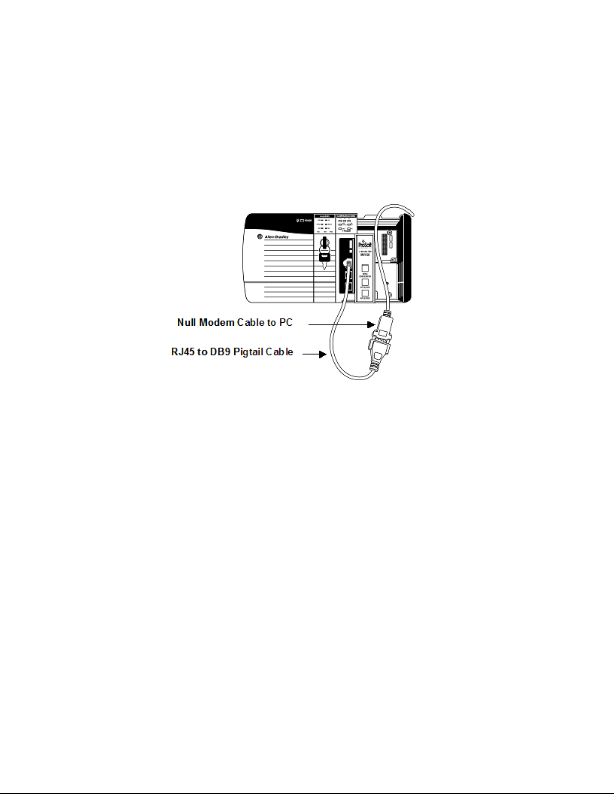
1.8 Connect your PC to the Module
With the module securely mounted, connect your PC to the
Configuration/Debug port using an RJ45-DB-9 Serial Adapter Cable and a Null
Modem Cable.
1 Attach both cables as shown.
2 Insert the RJ45 cable connector into the Configuration/Debug port of the
module.
3 Attach the other end to the serial port on your PC.
Page 20 of 98 ProSoft Technology, Inc.
August 30, 2010
Page 21

MVI56-LTQ ♦ ControlLogix Platform Configuring the MVI56-LTQ Module
Limitorque Valve Actuator Master Communication Module User Manual
2 Configuring th e MVI56-LTQ Module
In This Chapter
Reference Documents
Configuration Object (LTQCfg) .............................................................. 22
Configuration Data ................................................................................ 23
This chapter gives you a summary of all possible configuration parameters and their allowable settings and ranges. For more detailed information on configuration and operation options, please refer to the Reference chapter.
2.1 Reference Documents
The following Limitorque supporting documents can assist you in deploying your
network. These documents may be obtained from your local Limitorque
representative or downloaded from the Flowserve Corporation website:
http://www.flowserve.com/Products/Heritage-Brands/ch.Limitorque.literature
Wiring Specifications
http://www.flowserve.com/files/Files/Literature/ProductLiterature/FlowControl/
Limitorque/440-15001.pdf
Register mapping and communications
http://www.flowserve.com/files/Files/Literature/Products/Flowcontrol/Limitorqu
e/LMAIM4019.pdf
Modbus information and wiring
http://www.flowserve.com/files/Files/Literature/Products/Flowcontrol/Limitorqu
e/LMAIM1329.pdf
........................................................................... 21
ProSoft Technology, Inc. Page 21 of 98
August 30, 2010
Page 22

Configuring the MVI56-LTQ Module MVI56-LTQ ♦ ControlLogix Platform
Name
Data Type
Description
BaudRate
INT
Baudrate for port (110 to 115.2K)
MsgRespTm
INT
Message Response Timeout
MaxSlaves
INT
Maximum number of slaves to consider
BTRMax
BlkDelay
Block transfer delay counter
LastState
INT
State for slave data on comm failure
NetPoll
INT
Network polling scheme (0=A/B, 1=A, 2=B)
PropDelay
INT
Propagation delay for messages
RTSOn
INT
RTS to TxD delay (milliseconds)
INT
Special polling used (0=No, 1=T-MID, 2=Reg 6/7;
Use_CTS
INT
Monitor CTS line (0=No, 1=Yes)
BlkFailCnt
INT
Number of failed transfers before COM shutdown
ActiveSlaves
INT[10]
Array to set active slaves (1-bit/slave)
User Manual Limitorque Valve Actuator Master Communication Module
2.2 Configuration Object (LTQCfg)
The configuration object LTQCfg contains all the configuration information
required by the module. Fill in the members of this object to set the parameters
required for each application. This data set will be transferred from the processor
to the module each time a restart (warm or cold boot) operation is requested.
Configuration of the module is performed by filling in the values in the module
object defined in the Controller Tags Edit Tags dialog box. Each parameter
required by the module has a defined location in the object. The following table
describes the structure of the object.
INT
INT
SpecPolling
Maximum BTR block count
other numbers of the range 1 to 65535 refer to the
corresponding register).
Each parameter contained in this object is described in MVI56-LTQ Configuration
Data Definition (page 23). Ensure that you fill in each parameter carefully for
successful application of the module in a system.
Page 22 of 98 ProSoft Technology, Inc.
August 30, 2010
Page 23

MVI56-LTQ ♦ ControlLogix Platform Configuring the MVI56-LTQ Module
Value
Baud Rate
1200
1200 Baud
2400
2400 Baud
4800
9600
19200
19200 Baud
38400
38400 Baud
57600
57600 Baud
115200
115200 Baud
Limitorque Valve Actuator Master Communication Module User Manual
2.3 Configuration Data
This section contains listings of the MVI56-LTQ module’s configuration that is
read from the ControlLogix processor when the module first initializes.
2.3.1 BaudRate
The baud rate at which the port is to operate. The available configurations are as
follows:
* Limitorque Field Unit Factory Default Setting
2.3.2 MsgRespTm
This register represents the message response timeout period in 1 millisecond
increments. This is the time which a port configured as a Master will wait before
re-transmitting a command if no response is received from the addressed slave.
The value is set depending on the expected slave response times.
A value of 200 milliseconds should be the minimal setting. Values from 200 to
65535 (0xffff) are permitted.
4800 Baud
9600 Baud *
2.3.3 MaxSlaves
This value is used by the module to optimize the number of slaves polled by the
module. The value entered here can range from 1 to 150, and should always
meet or exceed the last slave in the Active Slave Table.
2.3.4 BTRMax
This value is not used in the current version of the software.
ProSoft Technology, Inc. Page 23 of 98
August 30, 2010
Page 24

Configuring the MVI56-LTQ Module MVI56-LTQ ♦ ControlLogix Platform
Value
Description
0
Maintain last data values
Value
Description
0
Port 1 polling only
2
Port 2 polling only
User Manual Limitorque Valve Actuator Master Communication Module
2.3.5 BlkDelay
This is an empirical value used by the module to balance the amount of time the
module spends block transferring and the amount spent handling port
communications. The value entered is used as a loop counter in the module,
where each time through the loop the count is incremented. When the count
equals the Block Transfer Delay Counter a Block Transfer sequence is initiated.
Example: In Master Mode applications with the module in a remote rack, the
frequency of command execution can be improved by entering a value of 75 to
150. The value must be determined empirically.
2.3.6 LastState
This value determines the state of the Limitorque read register values that are
returned to the PLC upon the detection of a communication failure state (that is,
comm has failed on both Port A and B).
Clear last data values (default)
1
2.3.7 NetPoll
Loop Mode (Port 1 and 2 alternating)
1
The Network Loop Mode emulates Limitorque’s polling scheme that takes
advantage of the actuator ability to repeat data transmissions and to operate in a
looped mode. In this mode, the module will alternate communications between
Port 1 and 2. Command failures on one port will be retried on the other port.
Page 24 of 98 ProSoft Technology, Inc.
August 30, 2010
Page 25

MVI56-LTQ ♦ ControlLogix Platform Configuring the MVI56-LTQ Module
Value
Number of Slaves
0
1 to 20
10
21 to 40
15
61 to 80
25
81 to 100
30
101 to 120
35
121 to 140
40
141 to 150
Limitorque Valve Actuator Master Communication Module User Manual
2.3.8 PropDelay
Provides a delay time between primary port polls to prevent network collisions on
port changeover. Values should be no lower than the listed minimal settings. The
value represents delay time in milliseconds.
41 to 60
20
Note: These values are reference only. Empirical data gathered on site will enable proper
adjustment of these values.
Slave #1 Channel A Fail bit (port 1) being true AND all other slave
communications not in fault will be an indication of improper adjustment of this
value.
2.3.9 RTSOn
This value represents the time in 1 millisecond increments for delay between
asserting RTS and the actual transmission of data. Delay between the receipt of
messages and transmit of new message must be greater than 10 milliseconds.
When used, a value of 20 is typically inserted into this field.
Note: This value is reference only. Empirical data gathered on site will enable proper adjustment of
these values.
ProSoft Technology, Inc. Page 25 of 98
August 30, 2010
Page 26

Configuring the MVI56-LTQ Module MVI56-LTQ ♦ ControlLogix Platform
Value
Description
0
Disabled
1
2
Registers 6/7, Analog Input 1 and 2
Any value other than 0, 1, or 2 will tell the module to poll that corresponding
User Manual Limitorque Valve Actuator Master Communication Module
2.3.10 SpecPolling
Enables polling of specific registers in addition to the standard polling. A value
other than zero will cause an additional poll request to be sent to the slaves that
are enabled. The results are placed in registers 8 and 9 in the slave response
data block.
Using this feature has a performance cost as the time available for the standard
polling is shared with the special polling.
Register 55, TP_BEFORE_MID_T_HIGH
3 to 65535
register number. This been added to allow for expanded use of the
SpecPolling tag. If low byte is set to 1 or 2 then the existing logic will will
remain consistent for backwards compatibility.
2.3.11 Use_CTS
This parameter defines if the CTS line is to be monitored for the communication
process. If the parameter is set to 0, the line will not be monitored. If the
parameter is set to 1, the modem control line must be set after the RTS line is
asserted for communications to occur.
2.3.12 BlkFailCnt
This parameter defines the number of successive block transfers that must occur
before the communication channels are shutdown. If the value is set to 0,
communications will continue on the ports even if the data transfer between the
processor and module fails. If the value is set to greater-than 0, the module will
suspend communications when the number of block transfer failures set is
exceeded. The valid range for this parameter is 0 to 65535.
Page 26 of 98 ProSoft Technology, Inc.
August 30, 2010
Page 27

MVI56-LTQ ♦ ControlLogix Platform Configuring the MVI56-LTQ Module
Index
Description
0
Slaves 1 to 16
1
2
Slaves 33 to 48
3
Slaves 49 to 64
4
Slaves 65 to 80
5
Slaves 81 to 96
6
Slaves 97 to 112
7
Slaves 113 to 128
8
9
Slaves 145 to 150
Limitorque Valve Actuator Master Communication Module User Manual
2.3.13 ActiveSlaves
These 10 words allow the user to configure the specific slaves that are active on
a network. The intent of this table is to allow the user to selectively enable slave
addresses and therefore not have to be concerned about activating slave
addresses continuously.
All values are entered into the table in a right to left order with bit 0 representing
the lower address. The slave addresses are mapped into the table as follows:
Slaves 17 to 32
Slaves 129 to 144
ProSoft Technology, Inc. Page 27 of 98
August 30, 2010
Page 28

Configuring the MVI56-LTQ Module MVI56-LTQ ♦ ControlLogix Platform
User Manual Limitorque Valve Actuator Master Communication Module
Page 28 of 98 ProSoft Technology, Inc.
August 30, 2010
Page 29

MVI56-LTQ ♦ ControlLogix Platform Ladder Logic
Limitorque Valve Actuator Master Communication Module User Manual
3 Ladder Logic
In This Chapter
Module Data Object (LTQModuleDef)
Adding the Module to an Existing Project .............................................. 34
................................................... 30
Ladder logic is required for application of the MVI56-LTQ module. Tasks that
must be handled by the ladder logic are module data transfer, special block
handling, and status data receipt. Additionally, a power-up handler may be
needed to handle the initialization of the module’s data and to clear any
processor fault conditions.
The sample ladder logic, on the ProSoft Solutions CD-ROM, is extensively
commented, to provide information on the purpose and function of each rung. For
most applications, the sample ladder will work without modification.
ProSoft Technology, Inc. Page 29 of 98
August 30, 2010
Page 30

Ladder Logic MVI56-LTQ ♦ ControlLogix Platform
Name
Data Type
Description
Cfg
Module Setup information
Stat
LTQStat
Status information in each read block
BP
LTQBackplane
Data to handle backplane logic
Valve
LTQValve[150]
Valve data
DoneBits
INT[10]
Done bit data for commands
Open
INT[10]
Open Command bits
Stop
Close
Close Command bits
InitESD
INT[10]
Initiate ESD bits
TermESD
INT[10]
Terminate ESD bits
Reset
INT[10]
Reset Command bits
Contactors
LTQCont[6]
Contactors #1 to #6 engage/disengage bits
AnalogCmd
User Manual Limitorque Valve Actuator Master Communication Module
3.1 Module Data Object (LTQModuleDef)
All data related to the MVI56-LTQ is stored in a user defined data type. An
instance of the data type is required before the module can be used. This is done
by declaring a variable of the data type in the Controller Tags Edit Tags dialog
box. The following table describes the structure of this object.
LTQCfg
INT[10]
INT[10]
INT[10]
AnalogPos
INT[150] Analog valve positions (0-100) to be used for
Stop Command bits
Command valve to set analog position bits
set cmd
This object contains objects that define the configuration, status and user data
related to the module. Each of these object types is discussed in the following
topics of the document.
Page 30 of 98 ProSoft Technology, Inc.
August 30, 2010
Page 31

MVI56-LTQ ♦ ControlLogix Platform Ladder Logic
Name
Data Type
Description
Product
INT[2]
Product code
Revision
INT[2]
Revision
OpSys
Run number
PassCnt
INT
Program scan counter
Queue
INT
Number of entries used in command queue
BTR_Cnt
INT
Number of BTR’s
BTW_Cnt
INT
Number of BTW’s
BlkParse
INT
Number of BTW blocks parsed
BlkEvent
Number of block transfer errors
CurSlave
INT
Current slave number being processed
CurPort
INT
Active port used on module (0=A, 1=B)
INT
Other port being tried after failure (0=No,
INT
Special Poll (0=No, 1=T_M, 2=Reg 6/7, 3 to
State
INT
Communication state machine value
ComState
INT
Communication state machine for port activity
CfgErr
INT
Module Configuration Error
Limitorque Valve Actuator Master Communication Module User Manual
3.1.1 Status Object (LTQStat)
This object views the status of the module. The LTQStat object shown below is
updated each time a read block is received by the processor. Use this data to
monitor the state of the module at a "real-time rate" .
Operating system code
Number of event commands received
1=Yes)
65535=corresponding register v alue)
Run
BlkErr
AltPort
SpecPoll
INT[2]
INT[2]
INT
INT
Refer to MVI56-LTQ Status Data Definition (page 76) for a complete listing of
data stored in this object.
ProSoft Technology, Inc. Page 31 of 98
August 30, 2010
Page 32

Ladder Logic MVI56-LTQ ♦ ControlLogix Platform
Name
Data Type
Description
LastRead
INT
Index of last read block
LastWrite
INT
Index of last write block
BlockIndex
INT
Computed block offset for data table
Name
Data Type
Description
Valve
DoneBits
INT[10]
Open Command bits
Stop
INT[10]
Stop Command bits
Close
INT[10]
Close Command bits
InitESD
INT[10]
Initiate ESD bits
TermESD
INT[10]
Terminate ESD bits
Reset
Contactors
INT[10]
Command valve to set analog position bits
INT[150]
Analog valve positions (0-100) to be used for
Name
Data Type
Description
ValvePos
INT
Position of valve 0-100%
Status
INT
Status Register BIts
Fault
DOut
DIn1
INT
Digital Input 1 bits
DIn2
INT
Digital Input 2 bits
ComStatus
INT
Communication Status Code
INT
Communication poll counter (0-32767) for
SPoll1
INT
Special polling register #55
SPoll2
INT
Special polling register #6 and #7
SPoll3-SPoll65535
INT
Special Polling register #3 to #65535
User Manual Limitorque Valve Actuator Master Communication Module
3.1.2 User Data Objects
These objects hold data to be transferred between the processor and the MVI56LTQ module. The first user data object is the LTQBackplane object that contains
the variables required by the ladder logic program for data transfer between the
module and the processor. The following table describes the structure of this
object.
Values in this structure are used by the ladder logic and initialized by the powerup function. The values in this block should change very rapidly as the transfer
process is very fast.
The last set of user data is shown in the following illustration:
LTQValve[150]
INT[10]
Open
Valve data
Done bit data for commands
INT[10]
LTQCont[6]
AnalogCmd
AnalogPos
Reset Command bits
Contactors #1 to #6 engage/disengage bits
set cmd
The value array stores data transferred from the module to the processor. The
following table describes the structure of each element in the array.
INT
INT
ComCntr
Fault Register Bits
Digital Output Bits
success
Page 32 of 98 ProSoft Technology, Inc.
August 30, 2010
Page 33

MVI56-LTQ ♦ ControlLogix Platform Ladder Logic
Name
Data Type
Description
Engage
INT[10]
Engage Command
Disengate
INT[10]
Disengage Command
Limitorque Valve Actuator Master Communication Module User Manual
Information in this structure contains the status and monitor information for each
valve in the system. This information should be considered by the user control
logic to determine the status and control required for each valve to be utilized in a
system. It is important to note that slave 1 has an array index of 0. This offset
applies to all valves (slave 150 has an index of 149).
The next data set received from the module is the DoneBits array. Each slave in
the system is associated with a bit in the array. Each element contains the done
bit status for 16 slave units ([0]=slaves 1 to 16, [1]=slaves 17 to 32, and so on). It
is important to use these bits to clear the commands issued using the next data
sets. Commands issued to the module to generate messages on the Limitorque
Valve Network are issued in a one-shot operation. After an event command is
issued to the slave, the done bit for the slave is set. This bit is held high for one
scan of the module and then is reset in the data transfer block. Ladder logic
should clear the commands for each slave using the status of the done bit.
The last set of data in the module object contains the control information for the
valves. This data is to be controlled by the ladder logic. An array is defined for
each of the command instructions available through the module. Each bit in the
array is associated with a slave. Bit 0 in word 0 corresponds to slave 1, and Bit 0
in word 1 corresponds to slave 17. An array of LTQCont objects is defined for the
contactor engage/disengage commands. The following table describes the
structure of this object.
In order to execute one of the commands, set the bit for the selected slave in the
array. For example, to open slave-3 valve, set bit 2 in word 0 of the Open array.
For the analog control commands, set the value for the analog first (AnalogPos[
]), then set the analog control array bit (AnalogCmd[ ]). The analog position
requires two commands. The first command issued by the module sets the
position in the valve. The second command instructs the valve to seek the new
position.
ProSoft Technology, Inc. Page 33 of 98
August 30, 2010
Page 34
Ladder Logic MVI56-LTQ ♦ ControlLogix Platform
User Manual Limitorque Valve Actuator Master Communication Module
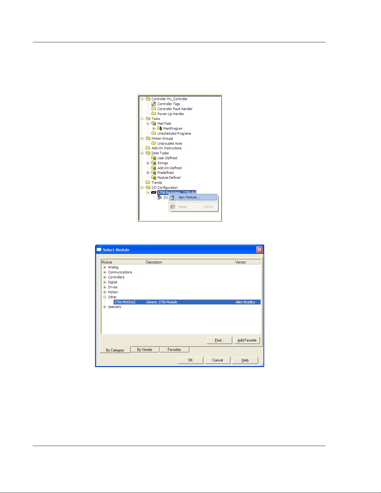
3.2 Adding the Module to an Existing Project
1 Select the I/O Configuration folder in the Controller Organization window of
RSLogix 5000, and then click the right mouse button to open a shortcut
menu. On the shortcut menu, choose N
EW MODULE.
This action opens the Select Module dialog box:
2 Select the 1756-M
ODULE (GENERIC 1756 MODULE) from the list and click OK.
This action opens the New Module dialog box.
Page 34 of 98 ProSoft Technology, Inc.
August 30, 2010
Page 35
MVI56-LTQ ♦ ControlLogix Platform Ladder Logic
Parameter
Value
Name
Enter a module identification string. Example: LTQ_2.
Comm Format
Select D
-INT.
Input Assembly Instance
1
Input Size
250
Output Assembly Instance
2
248
Configuration Assembly Instance
4
Configuration Size
0
Limitorque Valve Actuator Master Communication Module User Manual
3 Enter the Name, Description and Slot options for your application. You must
select the Comm Format as D
module will not communicate. Click OK to continue.
Description
Slot
Output Size
ATA - INT in the dialog box, otherwise the
Enter a description for the module. Example: Limitorque
Valve Actuator Master Communication Module
ATA
Enter the slot number in the rack where the MVI56-LTQ
module is located.
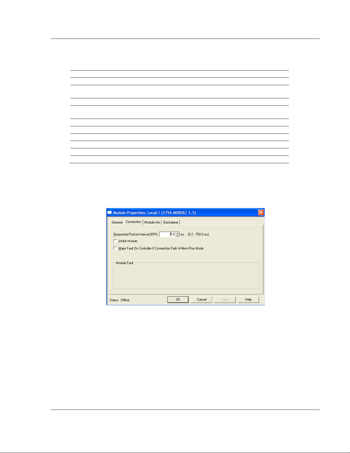
4 Select the Requested Packet Interval value for scanning the I/O on the
module. This value represents the minimum frequency that the module will
handle scheduled events. This value should not be set to less than 1
millisecond. The default value is 5 milliseconds. Values between 1 and 10
milliseconds should work with most applications.
ProSoft Technology, Inc. Page 35 of 98
August 30, 2010
Page 36
Ladder Logic MVI56-LTQ ♦ ControlLogix Platform
User Manual Limitorque Valve Actuator Master Communication Module
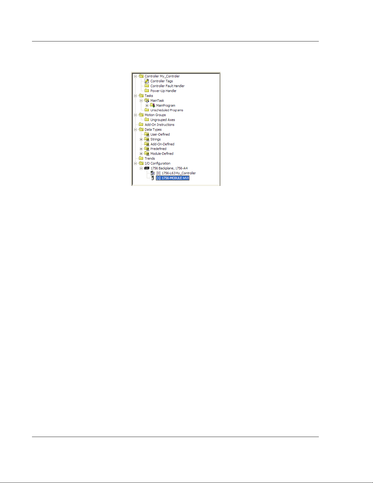
5 SAVE the module. Click OK to dismiss the dialog box. The Controller
Organization window now displays the module's presence.
6 Copy the User Defined Data Types from the sample program into your
existing RSLogix 5000 project.
7 Copy the Controller Tags from the sample program into your project.
8 Copy the Ladder Rungs from the sample program into your project.
Page 36 of 98 ProSoft Technology, Inc.
August 30, 2010
Page 37

MVI56-LTQ ♦ ControlLogix Platform Diagnostics and Troubleshooting
Limitorque Valve Actuator Master Communication Module User Manual
4 Diagnostics an d Troubleshootin g
In This Chapter
LED Status Indicators
Using the Configuration/Debug Port ...................................................... 42
Reading Status Data from the Module .................................................. 43
............................................................................ 38
The module provides information on diagnostics and troubleshooting in the
following forms:
LED status indicators on the front of the module provide general information
on the module's status.
Status Data contained in the module can be viewed through the
Configuration/Debug port, using the troubleshooting and diagnostic
capabilities of ProSoft Configuration Builder (PCB).
Status data values can be transferred from the module to processor memory
and can be monitored there manually or by customer-created logic. For
details on Status Data values, see MVI56-LTQ Status Data Area.
ProSoft Technology, Inc. Page 37 of 98
August 30, 2010
Page 38

Diagnostics and Troubleshooting MVI56-LTQ ♦ ControlLogix Platform
LED
Color
Status
Indication
Off
No data is being transferred on the Configuration/Debug port.
Off
No data is being transferred on the port.
Off
No data is being transferred on the port.
Amber
On
The LED is on when the module is performing a write
Off
The LED is off when the module is performing a read
The battery voltage is OK and functioning.
On
The battery voltage is low or battery is not present. Allow
User Manual Limitorque Valve Actuator Master Communication Module
4.1 LED Status Indicators
The LEDs indicate the module’s operating status as follows:
CFG
P1
P2
APP
BP ACT
OK
BAT
Green On Data is being transferred between the module and a remote
Green On Data is being transferred between the module and the
Green On Data is being transferred between the module and the
Amber Off
On The MVI56-LTQ module program has recognized a
Red/
Green
Red Off
Off The card is not receiving any power and is not securely
Green
Red The program has detected an error or is being configured. If
terminal using the Configuration/Debug port.
Limitorque network on Port A.
Limitorque network on Port B.
The MVI56-LTQ is working normally.
communication error on one of its ports.
operation on the backplane.
operation on the backplane. Under normal operation, the LED
should blink rapidly on and off.
plugged into the rack.
The module is operating normally.
the LED remains red for over 10 seconds, the program has
probably halted. Remove the card from the rack and re-insert
the card to restart the module’s program.
battery to charge by keeping module plugged into rack for 24
hours. If BAT LED still does not go off, contact ProSoft
Technology, as this is not a user serviceable item.
Page 38 of 98 ProSoft Technology, Inc.
August 30, 2010
Page 39

MVI56-LTQ ♦ ControlLogix Platform Diagnostics and Troubleshooting
Bit
Description
Value
0
Invalid baud rate specified.
0x0001
1
Message response timeout < 200.
0x0002
2
Maximum slave count > 150.
0x0004
3
0x0010
5
Invalid network polling scheme value (must be 0, 1 or 2).
0x0020
0x0080
0x0100
0x0200
0x1000
0x2000
0x4000
0x8000
Limitorque Valve Actuator Master Communication Module User Manual
During module configuration, the OK LED will be red and the APP and BP ACT
LEDs will be on. The bits in the configuration word are shown in the following
table. The module configuration error word has the following definition:
Maximum slave count = 0.
4
7
8
9
10
11
12
13
14
15
0x0008
0x0400
0x0800
Correct any invalid data in the configuration for proper module operation. When
the configuration contains a valid parameter set, all the bits in the configuration
word will be clear. This does not indicate that the configuration is valid for the
user application. Make sure each parameter is set correctly for the specific
application.
If the APP, BP ACT and OK LEDs blink at a rate of every one-second, this
indicates a serious problem with the module. Call ProSoft Technology support to
arrange for repairs.
4.1.1 Clearing a Fault Condition
Typically, if the OK LED on the front of the module turns RED for more than ten
seconds, a hardware problem has been detected in the module or the program
has exited.
To clear the condition, follow these steps:
1 Turn off power to the rack.
2 Remove the card from the rack.
3 Verify that all jumpers are set correctly.
4 If the module requires a Compact Flash card, verify that the card is installed
correctly.
5 Re-insert the card in the rack and turn the power back on.
6 Verify correct configuration data is being transferred to the module from the
ControlLogix controller.
If the module's OK LED does not turn GREEN, verify that the module is inserted
completely into the rack. If this does not cure the problem, contact ProSoft
Technology Technical Support.
ProSoft Technology, Inc. Page 39 of 98
August 30, 2010
Page 40

Diagnostics and Troubleshooting MVI56-LTQ ♦ ControlLogix Platform
Problem description
Steps to take
Verify that the module is plugged into the slot that has been configured
Problem description
Steps to take
The program has halted or a critical error has occurred. Connect to the
User Manual Limitorque Valve Actuator Master Communication Module
4.1.2 Troubleshooting
Use the following troubleshooting steps if you encounter problems when the
module is powered up. If these steps do not resolve your problem, please contact
ProSoft Technology Technical Support.
Processor Errors
Processor fault
Processor I/O LED
flashes
Module Errors
BP ACT LED (not
present on MVI56E
modules) remains OFF
or blinks slowly
MVI56E modules with
scrolling LED display:
<Backplane Status>
condition reads ERR
OK LED remains RED
for the module in the I/O Configuration of RSLogix.
Verify that the slot location in the rack has been configured correctly in
the ladder logic.
This indicates a problem with backplane communications. A problem
could exist between the processor and any installed I/O module, not just
the MVI56-LTQ. Verify that all modules in the rack are correctly
configured in the ladder logic.
This indicates that backplane transfer operations are failing. Connect to
the module’s Configuration/Debug port to check this.
To establish backplane communications, verify the following items:
The processor is in RUN or REM RUN mode.
The backplane driver is loaded in the module.
The module is configured for read and write data block transfer.
The ladder logic handles all read and write block situations.
The module is properly configured in the processor I/O configuration
and ladder logic.
Configuration/Debug port to see if the module is running. If the program
has halted, turn off power to the rack, remove the card from the rack and
re-insert it, and then restore power to the rack.
Page 40 of 98 ProSoft Technology, Inc.
August 30, 2010
Page 41

MVI56-LTQ ♦ ControlLogix Platform Diagnostics and Troubleshooting
Code
Name
Description
1
Illegal Function
An illegal function code request is being attempted.
Bad Data Address
The address or range of addresses, covered by a request
3
Bad Data Value
The value in the data field of the command is not allowed.
Module Busy
The module busy status code is returned when a write
CTS Line Error
The module is monitoring the CTS line and it was not
Send Timeout
The message was not completely transmitted on the port
No Message
The command selected did not produce a message (Bad
-10
Long Message
The message received on the port is too long.
-11
Response Timeout
Timeout condition while waiting for response message.
Wrong Slave
The response message received on the port is not that in
Wrong Function Code
The function code in the response message does not
Limitorque Valve Actuator Master Communication Module User Manual
4.1.3 Communication Error Codes
The Error Codes returned from the module represent the outcome of the
commands and responses executed by the module. This data value is returned
for each slave at word offset 6. Note that in all cases, if a zero is returned, there
is no current error. Valid Error Status Codes are as follows:
Note: These error codes are used for communication module diagnostics. For programming
purposes, use the Slave Data Table (Slave #x Response Data Word 1 bits 7, 10, and 11) for
determining slave communication status.
0
2
6
-1
-2
-3
All ok The module is operating as desired or is currently being
polled or commanded.
from the master are not within allowed limits.
command from the master has not yet been completed
when a second write command is received.
asserted after the RTS line was asserted. The message
was not transmitted on the port.
within the 5-second message send timeout period.
command format or illegal instr ucti on).
253
254
255
CRC Error The CRC value returned in the message does not match
ProSoft Technology, Inc. Page 41 of 98
August 30, 2010
the request message.
match that in the last request message.
the computed CRC of the packet.
Page 42

Diagnostics and Troubleshooting MVI56-LTQ ♦ ControlLogix Platform
Baud Rate
57,600
Parity
None
Data Bits
8
Stop Bits
1
Software Handshaking
User Manual Limitorque Valve Actuator Master Communication Module
4.2 Using the Configuration/Debug Port
To connect to the module’s Configuration/Debug port:
1 Connect your computer to the module’s port using a null modem cable.
2 Start the communication program on your computer and configure the
communication parameters with the following settings:
None
3 Open the connection. When you are connected, press the [?] key on your
keyboard. If the system is set up properly, you will see a menu with the
module name followed by a list of letters and the commands associated with
them.
If there is no response from the module, follow these steps:
1 Verify that the null modem cable is connected properly between your
computer’s serial port and the module. A regular serial cable will not work.
2 Verify that RSLinx is not controlling the COM port. Refer to Disabling the
RSLinx Driver for the Com Port on the PC.
3 Verify that your communication software is using the correct settings for baud
rate, parity and handshaking.
4 On computers with more than one serial port, verify that your communication
program is connected to the same port that is connected to the module.
If you are still not able to establish a connection, you can contact ProSoft
Technology Technical Support for further assistance.
Page 42 of 98 ProSoft Technology, Inc.
August 30, 2010
Page 43

MVI56-LTQ ♦ ControlLogix Platform Diagnostics and Troubleshooting
DOS
ProComm, as well as several other terminal emulation programs
Windows 3.1
Terminal
Windows 95/98
HyperTerminal
Windows NT/2000/XP
HyperTerminal
Limitorque Valve Actuator Master Communication Module User Manual
4.3 Reading Status Data from the Module
The MVI56-LTQ module returns a 22-word Status Data Block that can be used to
determine the module’s operating status. This data is transferred to the
ControlLogix processor continuously with each read block.
The Configuration/Debug port provides the following functionality:
Full view of the module’s configuration data
View of the module’s status data
Complete display of the module’s internal database (registers 0 to 3999)
Version Information
Control over the module (warm boot, cold boot, transfer configuration)
Facility to upload and download the module’s configuration file
4.3.1 Required Software
In order to send and receive data over the serial port (COM port) on your
computer to the module, you must use a communication program (terminal
emulator).
A simple communication program called HyperTerminal is pre-installed with
recent versions of Microsoft Windows operating systems. If you are connecting
from a machine running DOS, you must obtain and install a compatible
communication program. The following table lists communication programs that
have been tested by ProSoft Technology.
ProSoft Technology, Inc. Page 43 of 98
August 30, 2010
Page 44

Diagnostics and Troubleshooting MVI56-LTQ ♦ ControlLogix Platform
User Manual Limitorque Valve Actuator Master Communication Module
4.3.2 The Configuration/Debug Menu
The Configuration and Debug menu for this module is arranged as a tree
structure, with the Main Menu at the top of the tree, and one or more sub-menus
for each menu command. The first menu you see when you connect to the
module is the Main menu.
Because this is a text-based menu system, you enter commands by typing the
command letter from your computer keyboard in the terminal application (for
example, HyperTerminal). The module does not respond to mouse movements
or clicks. The command executes as soon as you press the command letter —
you do not need to press [Enter]. When you type a command letter, a new
screen will be displayed in your terminal application.
Navigation
All of the submenus for this module contain commands to redisplay the menu or
return to the previous menu. You can always return from a submenu to the next
higher menu by pressing [M]
The organization of the menu structure is represented in simplified form in the
following illustra tion:
on your keyboard.
The remainder of this section shows the menus available for this module, and
briefly discusses the commands available to you.
Keystrokes
The keyboard commands on these menus are usually not case sensitive. You
can enter most commands in lowercase or uppercase letters.
The menus use a few special characters (?,
as shown. Some of these characters will require you to use the SHIFT,
ALT
keys to enter them correctly. For example, on US English keyboards, enter
the ?
command as SHIFT and /.
Also, take care to distinguish the different uses for uppercase letter "eye" (I),
-, +, @) that must be entered exactly
CTRL, or
lowercase letter "el" (L), and the number one (1). Likewise, uppercase letter "oh"
(O)
and the number zero (0) are not interchangeable. Although these characters
look alike on the screen, they perform different actions on the module and may
not be used interchangeably.
Page 44 of 98 ProSoft Technology, Inc.
August 30, 2010
Page 45

MVI56-LTQ ♦ ControlLogix Platform Diagnostics and Troubleshooting
Limitorque Valve Actuator Master Communication Module User Manual
4.3.3 Main Menu
When you first connect to the module from your computer, your terminal screen
will be blank. To activate the main menu, press the [?] key on your computer’s
keyboard. If the module is connected properly, the following menu will appear.
Caution: Some of the commands available to you from this menu are designed for advanced
debugging and system testing only, and can cause the module to stop communicating with the
processor or with other devices, resulting in potential data loss or other failures. Only use these
commands if you are specifically directed to do so by ProSoft Technology Technical Support staff.
Some of these command keys are not listed on the menu, but are active nevertheless. Please be
careful when pressing keys so that you do not accidentally execute an unwanted command.
Opening the Data Analyzer Menu
Press [A] to open the Data Analyzer Menu. Use this command to view all bytes
of data transferred on each port. Both the transmitted and received data bytes
are displayed. Refer to Data Analyzer (page
47) for more information about this
menu.
Important: When in analyzer mode, program execution will slow down. Only use this tool during a
troubleshooting session. Before disconnecting from the Config/Debug port, please press [S] to stop
the data analyzer, and then press [M] to return to the main menu. This action will allow the module
to resume its normal high speed operating mode.
Viewing Block Transfer Statistics
Press [B] from the Main menu to view the Block Transfer Statistics screen.
Use this command to display the configuration and statistics of the backplane
data transfer operations between the module and the processor. The information
on this screen can help determine if there are communication problems between
the processor and the module.
Tip: To determine the number of blocks transferred each second, mark the numbers displayed at a
specific time. Then some seconds later activate the command again. Subtract the previous
numbers from the current numbers and divide by the quantity of seconds passed between the two
readings.
ProSoft Technology, Inc. Page 45 of 98
August 30, 2010
Page 46

Diagnostics and Troubleshooting MVI56-LTQ ♦ ControlLogix Platform
User Manual Limitorque Valve Actuator Master Communication Module
Viewing Module Configuration
Press [C] to view the Module Configuration screen.
Use this command to display the current configuration and statistics for the
module.
Opening the Database View Menu
Press [D] to open the Database View menu.
Use this menu command to view the current contents of the module’s database.
For more information about this submenu, see Database View Menu (page 52).
Viewing Version Information
Press [G] to view Version information for the module.
Use this command to view the current version of the software for the module, as
well as other important values. You may be asked to provide this information
when calling for technical support on the product.
Values at the bottom of the display are important in determining module
operation. The Program Scan Counter value is incremented each time a
module’s program cycle is complete.
Tip: Repeat this command at one-second intervals to determine the frequency of program
execution.
Warm Booting the Module
Press [W] from the Main menu to warm boot (restart) the module.
This command will cause the program to exit and reload, refreshing configuration
parameters that must be set on program initialization. Only use this command if
you must force the module to reboot.
Viewing Module Status
Press [1] to view information about Module Status. Use this command to view
status information about the module. This screen also contains useful information
for mailbox troubleshooting:
Scan count
Mailbox counters
Alarm counters
Number of acyclic read and write operations performed by the module.
You can also view the number of mailbox messages in the input and output
queues, and the number of alarms in the alarm queue.
Opening the Valve Data menu
Press [2] to display the data values for each valve. Refer to the Reference
chapter for a complete listing of this structure.
Page 46 of 98 ProSoft Technology, Inc.
August 30, 2010
Page 47

MVI56-LTQ ♦ ControlLogix Platform Diagnostics and Troubleshooting
Limitorque Valve Actuator Master Communication Module User Manual
Exiting the Program
Press [ESC] to restart the module and force all drivers to be loaded. The module
will use the configuration stored in the module's Flash memory to configure the
module.
4.3.4 Data Analyzer
The data analyzer mode allows you to view all bytes of data transferred on each
port. Both the transmitted and received data bytes are displayed. Use of this
feature is limited without a thorough understanding of the protocol.
Note: The Port selection commands on the Data Analyzer menu differs very slightly in different
modules, but the functionality is basically the same. Use the illustration above as a general guide
only. Refer to the actual data analyzer menu on your module for the specific port commands to
use.
Important: When in analyzer mode, program execution will slow down. Only use this tool during a
troubleshooting session. Before disconnecting from the Config/Debug port, please press [S] to stop
the data analyzer, and then press [M] to return to the main menu. This action will allow the module
to resume its normal high speed operating mode.
Analyzing Data for the first application port
Press [1] to display I/O data for the first application port in the Data Analyzer. The
following illustration shows an example of the Data Analyzer output.
Analyzing Data for the second application port
Press [2] to display I/O data for the second application port in the Data Analyzer.
ProSoft Technology, Inc. Page 47 of 98
August 30, 2010
Page 48
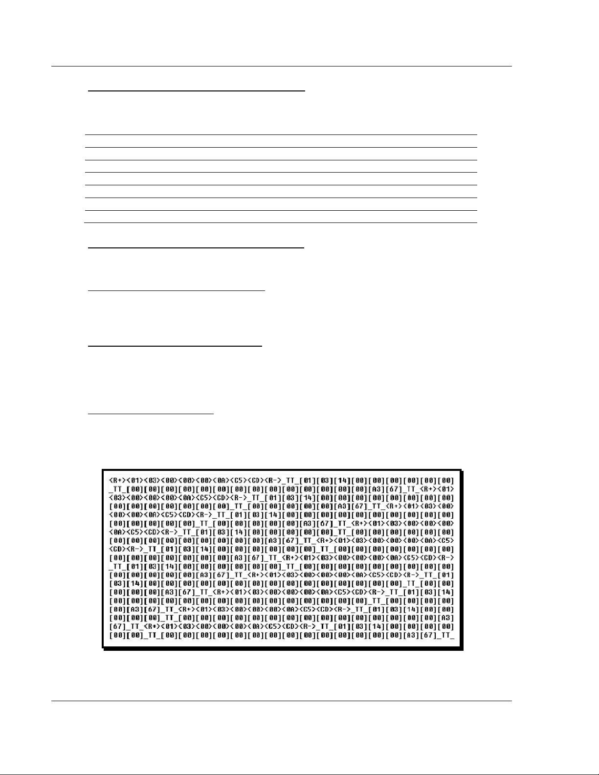
Diagnostics and Troubleshooting MVI56-LTQ ♦ ControlLogix Platform
Key
Interval
[5]
[6]
[7]
10 milliseconds ticks
[8]
50 milliseconds ticks
[9]
100 milliseconds ticks
[0]
Turn off timing marks
User Manual Limitorque Valve Actuator Master Communication Module
Displaying Timing Marks in the Data Analyzer
You can display timing marks for a variety of intervals in the data analyzer
screen. These timing marks can help you determine communication-timing
characteristics.
1 milliseconds ticks
5 milliseconds ticks
Removing Timing Marks in the Data Analyzer
Press [0] to turn off timing marks in the Data Analyzer screen.
Viewing Data in Hexadecimal Format
Press [H] from the Database View menu to display the data on the current page
in hexadecimal format.
Viewing Data in ASCII (Text) Format
Press [A] from the Database View menu to display the data on the current page
in ASCII format. This is useful for regions of the database that contain ASCII
data.
Starting the Data Analyzer
Press [B] to start the data analyzer. After the key is pressed, all data transmitted
and received on the currently selected port will be displayed. The following
illustration shows an example.
The Data Analyzer displays the following special characters:
Page 48 of 98 ProSoft Technology, Inc.
August 30, 2010
Page 49
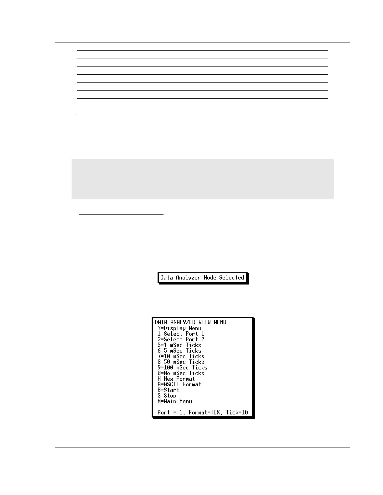
MVI56-LTQ ♦ ControlLogix Platform Diagnostics and Troubleshooting
Character
Definition
Data enclosed in these characters represent dat a receiv ed o n the port.
< >
Data enclosed in these characters represent data transmitted on the port.
<R+>
These characters are inserted when the RTS line is driven high on the port.
<R->
These characters are inserted when the RTS line is dropped low on the port.
<CS>
These characters are displayed when the CTS line is recognized high.
Limitorque Valve Actuator Master Communication Module User Manual
[ ]
_TT_
These characters are displayed when the timing mark interval has been reached.
This parameter is user defined.
Stopping the Data Analyzer
Press [S] to stop the data analyzer. Use this option to freeze the display so the
data can be analyzed. To restart the analyzer, press [B].
Important: When in analyzer mode, program execution will slow down. Only use this tool during a
troubleshooting session. Before disconnecting from the Config/Debug port, please press [S] to stop
the data analyzer, and then press [M] to return to the main menu. This action will allow the module
to resume its normal high speed operating mode.
Returning to the Main Menu Press [M] to return to the Main menu.
4.3.5 Data Analyzer Tips
From the main menu, press [A] for the "Data Analyzer". You should see the
following text appear on the screen:
After the "Data Analyzer" mode has been selected, press [?] to view the Data
Analyzer menu. You will see the following menu:
ProSoft Technology, Inc. Page 49 of 98
August 30, 2010
Page 50
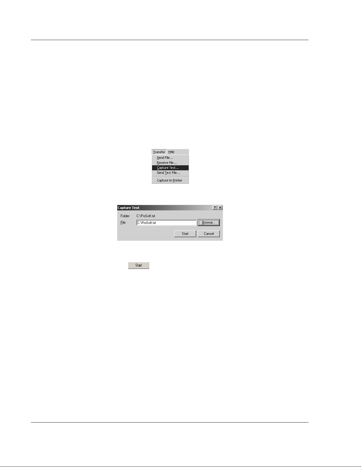
Diagnostics and Troubleshooting MVI56-LTQ ♦ ControlLogix Platform
User Manual Limitorque Valve Actuator Master Communication Module
From this menu, you can select the "Port", the "format", and the "ticks" that you
can display the data in.
For most applications, HEX is the best format to view the data, and this does
include ASCII based messages (because some characters will not display on
HyperTerminal and by capturing the data in HEX, we can figure out what the
corresponding ASCII characters are supposed to be).
The Tick value is a timing mark. The module will print a _TT for every xx
milliseconds of no data on the line. Usually 10milliseconds is the best value to
start with.
After you have selected the Port, Format, and Tick, we are now ready to start a
capture of this data. The easiest way to do so is to go up to the top of you
HyperTerminal window, and do a T
RANSFER / CAPTURE TEXT as shown below:
After selecting the above option, the following window will appear:
Next name the file, and select a directory to store the file in. In this example, we
are creating a file ProSoft.txt and storing this file on our root C: drive. After you
have done this, press the button.
Now you have everything that shows up on the HyperTerminal screen being
logged to a file called ProSoft.txt. This is the file that you will then be able to
email to ProSoft Technical Support to assist with issues on the communications
network.
Page 50 of 98 ProSoft Technology, Inc.
August 30, 2010
Page 51
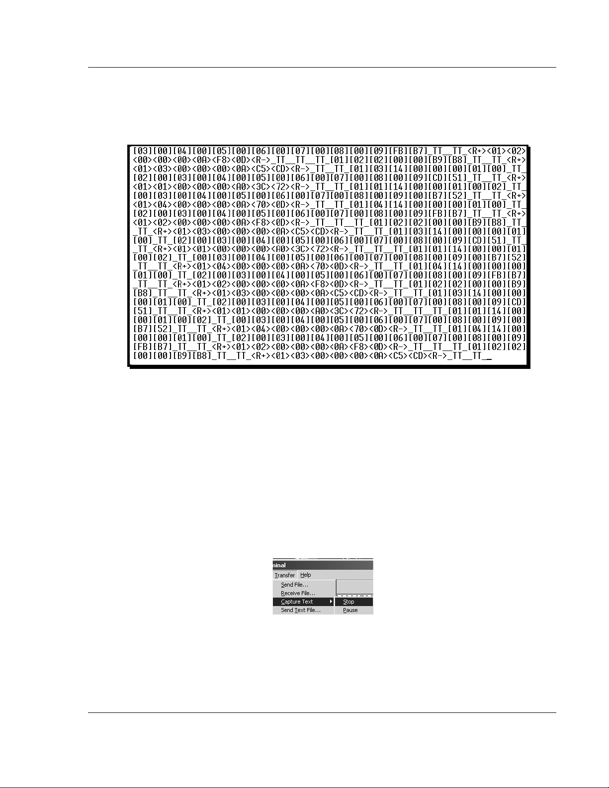
MVI56-LTQ ♦ ControlLogix Platform Diagnostics and Troubleshooting
Limitorque Valve Actuator Master Communication Module User Manual
To begin the display of the communications data, you will then want to press [B]
to tell the module to start printing the communications traffic out on the debug
port of the module. After you have pressed [B],
you should see something like
the following:
The <R+> means that the module is transitioning the communications line to a
transmit state.
All characters shown in <> brackets are characters being sent out by the module.
The <R-> shows when the module is done transmitting data, and is now ready to
receive information back.
And finally, all characters shown in the [ ] brackets is information being received
from another device by the module.
After taking a minute or two of traffic capture, you will now want to stop the "Data
Analyzer". To do so, press the [S] key, and you will then see the scrolling of the
data stop.
When you have captured the data you want to save, open the Transfer menu and
choose Capture Text. On the secondary menu, choose Stop.
You have now captured, and saved the file to your PC. This file can now be used
in analyzing the communications traffic on the line, and assist in determining
communication errors.
ProSoft Technology, Inc. Page 51 of 98
August 30, 2010
Page 52
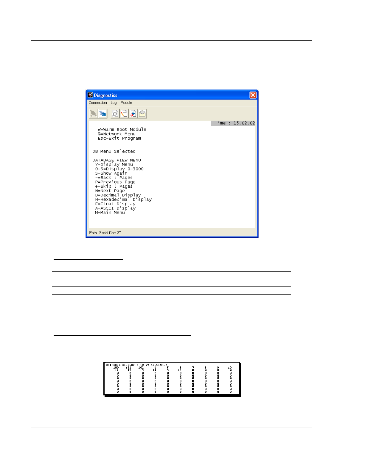
Diagnostics and Troubleshooting MVI56-LTQ ♦ ControlLogix Platform
Command
Description
[0]
Display registers 0 to 99
[1]
Display registers 1000 to 1099
[2]
Display registers 2000 to 2099
User Manual Limitorque Valve Actuator Master Communication Module
4.3.6 Database View Menu
Press [D] from the Main menu to open the Database View menu. Use this menu
command to view the current contents of the module database. Press [?]
a list of commands available on this menu.
to view
Viewing Register Pages
To view sets of register pages, use the keys described below:
And so on. The total number of register pages available to view depends on your
module’s configuration.
Displaying the Current Page of Registers Again
Press [S] from the Database View menu to show the current page of registers
again.
This screen displays the current page of 100 registers in the database.
Page 52 of 98 ProSoft Technology, Inc.
August 30, 2010
Page 53

MVI56-LTQ ♦ ControlLogix Platform Diagnostics and Troubleshooting
Limitorque Valve Actuator Master Communication Module User Manual
Moving Back Through 5 Pages of Registers
Press [-] from the Database View menu to skip five pages back in the database
to see the 100 registers of data starting 500 registers before the currently
displayed page.
Moving Forward Through 5 Pages of Registers
Press [+] from the Database View menu to skip five pages ahead in the database
to see the 100 registers of data starting 500 registers after the currently displayed
page.
Viewing the Previous 100 Registers of Data
Press [P] from the Database View menu to display the previous 100 registers of
data.
Viewing the Next 100 Registers of Data Press [N] from the Database View menu to display the next 100 registers of data.
Viewing Data in Decimal Format
Press [D] from t he Database View menu to display the data on the current page
in decimal format.
Viewing Data in Hexadecimal Format
Press [H] from the Database View menu to display the data on the current page
in hexadecimal format.
Viewing Data in Floating-Point Format
Press [F] from the Database View menu to display the data on the current page
in floating-point format. The program assumes that the values are aligned on
even register boundaries. If floating-point values are not aligned as such, they
are not displayed properly.
Viewing Data in ASCII (Text) Format
Press [A] from the Database View menu to display the data on the current page
in ASCII format. This is useful for regions of the database that contain ASCII
data.
Returning to the Main Menu
Press [M] to return to the Main menu.
ProSoft Technology, Inc. Page 53 of 98
August 30, 2010
Page 54

Diagnostics and Troubleshooting MVI56-LTQ ♦ ControlLogix Platform
Key
Function
Display valve 11
Display valve 31
Display valve 51
Display valve 61
Display valve 71
Display valve 81
Display valve 91
Display valve 101
Display valve 121
Display valve 141
User Manual Limitorque Valve Actuator Master Communication Module
4.3.7 Valve Data Menu
Press [2] to display the data values for each valve. Refer to the Reference
chapter for a complete listing of this structure.
Viewing Valve Registers
0 (zero) to E = Display 0 to 140
This command is used to jump to a specific set of registers in the database and
displays the data. The keys perform the following functions:
0
1
2
3
4
5
6
7
8
9
A
B
C
D
E
Display valve 1
Display valve 21
Display valve 41
Display valve 111
Display valve 131
Redisplaying the Current Page
Press [S] to display the current page of data.
Viewing the Next Page of Data
Press [N] to display the next page of data.
Viewing the Previous Page of Data
Press [P] to display the previous page of data.
Returning to the Main Menu
Press [M] to return to the Main menu.
Page 54 of 98 ProSoft Technology, Inc.
August 30, 2010
Page 55

MVI56-LTQ ♦ ControlLogix Platform Reference
Limitorque Valve Actuator Master Communication Module User Manual
5 Reference
In This Chapter
Product Specifications
Functional Overview .............................................................................. 58
Cable Connections ................................................................................ 68
MVI56-LTQ Database Definition ............................................................ 74
MVI56-LTQ Status Data Definition ........................................................ 76
LTQValve Object Definition ................................................................... 77
Command Usage for Limitorque Products............................................. 80
Polling Schemes .................................................................................... 82
Typical Network Loop ............................................................................ 85
........................................................................... 55
5.1 Product Specifications
The MVI56 Limitorque Valve Actuator Master Communication Module allows
ControlLogix compatible processors to interface easily with Limitorque Valve
Actuators and other Limitorque protocol compatible devices.
The MVI56-LTQ module acts as an input/output module between the Limitorque
valve network and the ControlLogix processor. The data transfer from the
ControlLogix processor is asynchronous from the actions on the network. The
1500-word register space in the module transfers the valve information from the
module to the processor. Ladder logic is responsible for control of the valves.
Data transferred from the processor to the module instructs the module to
execute commands to valves on the Limitorque network.
5.1.1 General Specifications
Single Slot - 1756 backplane compatible
Local or remote rack
The module is recognized as an Input/Output module and has access to
processor memory for data transfer between processor and module
Ladder Logic is used for data transfer between module and processor.
Configuration data obtained through user-defined ladder. Sample ladder file
included
ProSoft Technology, Inc. Page 55 of 98
August 30, 2010
Page 56

Reference MVI56-LTQ ♦ ControlLogix Platform
Specification
Description
800 mA @ 5 VDC
Operating Temperature
0 to 60°C (32 to 140°F)
Storage Temperature
-40 to 85°C (-40 to 185°F)
30g Operational
5 to 95% (non-condensing)
Module Status
RJ45 (DB-9M with supplied cable)
Baud rate: 110 to 115,200 baud, depending on
RJ45 (DB-9M with supplied cable)
RJ45 to DB-9M cables for each port
User Manual Limitorque Valve Actuator Master Communication Module
5.1.2 Hardware Specifications
Backplane Current Load
Shock
Relative Humidity
LED Indicators
Debug/Configuration port (CFG)
CFG Port (CFG)
Application ports (PRT1 & PRT2)
Full hardware handshaking control, prov idi ng radio, modem and multi-drop support
Software configurable
communication parameters
App Ports (P1, P2) (Serial
modules)
Shipped with Unit
3 mA @ 24 VDC
50g non-operational
Vibration: 5 g from 10 to 150 Hz
Backplane Transfer Status
Application Status
Serial Activity
RS-232 only
protocol
RS-232, 485 and 422
Parity: none, odd or even
Data bits: 5, 6, 7, or 8
Stop bits: 1 or 2
RTS on/off delay: 0 to 65535 milliseconds
RS-232 handshaking configurable
500V Optical isolation from backplane
6-foot RS-232 configuration cable
Page 56 of 98 ProSoft Technology, Inc.
August 30, 2010
Page 57

MVI56-LTQ ♦ ControlLogix Platform Reference
Limitorque Valve Actuator Master Communication Module User Manual
5.1.3 Functional Specifications
Support for the storage and transfer of up to 150 valves to the ControlLogix
processor’s controller tags
Emulates Limitorque’s Port A/B polling scheme using both ports on the
module
Supports the following valves
o MX/DDC Modbus
o UEC-3-DDC Modbus
o DDC-100M I/O module
o DDC-100M field unit
o Valvcon IVO (unit in multi-drop mode only)
Software configuration
o Baud rate: 1200 to 115200
o Message response timeout
o Number of active slaves
o Last state on communication failure for valve data
o Network polling scheme
o Active slave table (bit mapped)
o Use of CTS module line option
o Backplane failure affect on communication port availability
Support command
o Continuously polled
o Read registers 40008 to 40013, optional 40055 or 40006/40007
o Commands: open, stop, close, initiate network ESD, terminate network
ESD, engage contactors 1 to 6, disengage contactors 1 to 6, position
valve (0 to 100%)
Data returned to the processor for each valve
o Valve position
o Status register
o Fault register
o Digital out p uts
o Digital inputs registers 1 and 2
o Communication error code
o Communication poll counter
o Special polled registers
ProSoft Technology, Inc. Page 57 of 98
August 30, 2010
Page 58

Reference MVI56-LTQ ♦ ControlLogix Platform
User Manual Limitorque Valve Actuator Master Communication Module
5.2 Functional Overview
5.2.1 General Concepts
The following discussion explains several concepts that are important for
understanding module operation.
ControlLogix Processor Not in Run
Whenever the module detects that the processor has gone out of the Run mode
(that is, Fault or PGM), the ports can be shut down as prescribed in the user
configuration. When the processor is returned to a running state, the module will
resume communications on the network.
Backplane Data Transfer
The MVI56-LTQ module communicates directly over the ControlLogix backplane.
Data is paged between the module and the ControlLogix processor across the
backplane using the module's input and output images. The update frequency of
the images is determined by the scheduled scan rate defined by the user for the
module and the communication load on the module. Typical updates are in the
range of 1 to 10 milliseconds.
This bi-directional transference of data is accomplished by the module filling in
data in the module's input image to send to the processor. Data in the input
image is placed in the Controller Tags in the processor by the ladder logic. The
input image for the module is set to 250 words. This large data area permits fast
throughput of data between the module and the processor.
The processor inserts data to the module's output image to transfer to the
module. The module's program extracts the data and places it in the module's
internal database. The output image for the module is set to 248 words. This
large data area permits fast throughput of data from the processor to the module.
Page 58 of 98 ProSoft Technology, Inc.
August 30, 2010
Page 59

MVI56-LTQ ♦ ControlLogix Platform Reference
Limitorque Valve Actuator Master Communication Module User Manual
The following illustration shows the data transfer method used to move data
between the ControlLogix processor, the MVI56-LTQ module and the Limitorque
valve network.
All data transferred between the module and the processor over the backplane is
through the input and output images. Ladder logic must be written in the
ControlLogix processor to interface the input and output image data with data
defined in the Controller Tags. All data used by the module is stored in its internal
database. The following illustration shows the layout of the database:
Module’s Internal Database Structure
1500 registers for user data
Register Data
2500 words of control data
Control Data
0
1499
1500
3999
ProSoft Technology, Inc. Page 59 of 98
August 30, 2010
Page 60

Reference MVI56-LTQ ♦ ControlLogix Platform
Block Number
Description
On read, this block contains the valve information for slaves 1 to 20. For the
On read, this block contains the valve information for slaves 21 to 40. For the
These blocks are only used for the read operation. They contain valve data for
9000
User Manual Limitorque Valve Actuator Master Communication Module
Data contained in this database is paged through the input and output images by
coordination of the ControlLogix ladder logic and the MVI56-LTQ module's
program. Up to 248 words of data can be transferred from the module to the
processor at a time. Up to 247 words of data can be transferred from the
processor to the module. The read and write block identification codes in each
data block determine the function to be performed or the content of the data
block. The block identification codes used by the module are listed below:
0
1
2 to 7
9998
9999
write operation, this block contains the digital command control data.
write operation, this block contains the analog command control data.
up to 20 slave units.
This is the configuration data block transferred from the processor
This block is sent from the processor to the module to instruct the module to
perform the warm-boot operat i on.
This block is sent from the processor to the module to instruct the module to
perform the cold-boot opera tio n.
Each image has a defined structure depending on the data content and the
function of the data transfer.
Page 60 of 98 ProSoft Technology, Inc.
August 30, 2010
Page 61

MVI56-LTQ ♦ ControlLogix Platform Reference
Word
Description
0
Reserved
1
BTW ID Requested (0 or 1)
2 to 201
Valve Data (20 valves each block)
202 to 211
Done Bit Data
212 to 213
Revision
216 to 217
Operating System
218 to 219
Run Number
220
Pass Count
221
Queue Size
222
BTR Count
223
BT Parse Count
225
BT Event Count
226
BT Error Count
227
Current Slave
228
Current Port
229
230
Special Poll Request
231
State
232
Comm State
233
CfgErr
234 to 248
Spare
249
BTR ID (0 to 7)
Limitorque Valve Actuator Master Communication Module User Manual
Normal Data Transfer
Normal data transfer includes the paging of the valve data found in the module’s
internal database in registers 0 to 1499, the status data and the done bit data
from the module to the processor. These data are transferred through read (input
image) blocks 0 to 7. Data transferred from the processor to the module is
through blocks 0 and 1. The structure and function of each block is discussed in
the following topics.
Read Block
These blocks of data transfer information from the module to the ControlLogix
processor. The structure of the input image used to transfer this data is shown
below:
Product Code
214 to 215
BTW Count
224
Alt Port
The Read Block ID is an index value used to determine the location of where the
data will be placed in the ControlLogix processor controller tag array of module
read data. Each transfer can move up to 200 words (block offsets 2 to 201) of
data representing the data for up to 20 valves. In addition to moving valve data,
the block also contains status data for the module. This last set of data is
transferred with each new block of data and is used for high-speed data
movement.
ProSoft Technology, Inc. Page 61 of 98
August 30, 2010
Page 62

Reference MVI56-LTQ ♦ ControlLogix Platform
Word
Description
202
Cmd Done - Slaves 1 to 16
203
204
Cmd Done - Slaves 33 to 48
205
Cmd Done - Slaves 49 to 64
206
Cmd Done - Slaves 65 to 80
207
Cmd Done - Slaves 81 to 96
208
Cmd Done - Slaves 97 to 112
209
210
211
Cmd Done - Slaves 145 to 150
User Manual Limitorque Valve Actuator Master Communication Module
The LTQ Module returns Done Bit Data to the ladder logic. A single bit is
returned per slave address, allowing ladder logic to be used to clear the
Command Enable bits. The following important points should be noted about the
Command Done bits:
1 There is only one bit returned per slave address, not one bit per command
per slave. The implication of this is that one Done Bit must be used to clear
all possible Enable bits for one slave address.
2 The Done Bit is a positive indication that the module executed the command.
It is NOT an indication of the command’s success. A Done Bit is returned to
the ladder logic whenever the command was completed without error or not.
This allows all commands to be unlatched. To determine if there is a
communication problem with a slave, verify the Channel A/B communication
status bits in the valve data Status field.
3 The Done Bit data registers in the module are cleared and then updated prior
to each backplane transfer sequence. This is done to ensure that the ladder
logic receives the quickest possible acknowledgment of a command’s
execution.
The structure of the Done Bit Data in the input image from the module is as
follows:
Cmd Done - Slaves 17 to 32
Cmd Done - Slaves 113 to 128
Cmd Done - Slaves 129 to 144
The following tables can be used to determine the slave associated with each bit
in the array. These tables can also be used with the digital control words
discussed in the following section. The following table lists the relationship
between the word/bit combination and the slave address on the Limitorque valve
network:
Page 62 of 98 ProSoft Technology, Inc.
August 30, 2010
Page 63

MVI56-LTQ ♦ ControlLogix Platform Reference
Limitorque Valve Actuator Master Communication Module User Manual
The following table lists the relationship between the word/bit combination and
the slave index in the module:
The module status data starts at word 212 in the read block. This information can
be used to determine the "health" of the module and should be moved to the
status object in the processor logic.
The Write Block ID associated with the block requests data from the ControlLogix
processor. Under normal program operation, the module sequentially sends read
blocks and requests write blocks. For example, if eight read and two write blocks
are used with the application, the sequence will be as follows:
R0W0R1W1R2W0R3W1R4W0R5W1R6W0R7W1R0W0
This sequence will continue until interrupted by other write block numbers sent by
the controller or by operator control through the module’s Configuration/Debug
port.
ProSoft Technology, Inc. Page 63 of 98
August 30, 2010
Page 64

Reference MVI56-LTQ ♦ ControlLogix Platform
Word
Description
BTW ID 0
1 to 10
Open
11 to 20
Stop
21 to 30
Close
31 to 40
Initiate ESD
41 to 50
Reset
61 to 70
Engage Contactor #1
71 to 80
Disengage Contactor #1
81 to 90
Engage Contactor #2
91 to 100
Disengage Contactor #2
101 to 110
111 to 120
Engage Contactor #4
131 to 140
Disengage Contactor #4
141 to 150
Engage Contactor #5
151 to 160
Disengage Contactor #5
161 to 170
Engage Contactor #6
171 to 180
181 to 247
Spare
Word
Description
0
BTW ID 1
1 to 10
11 to 160
161 to 247
User Manual Limitorque Valve Actuator Master Communication Module
Write Block
These blocks of data transfer control information from the ControlLogix processor
to the module. This control information issues commands to valves on the
network. Two blocks are defined in the module for this operation; Block 0 and
Block 1. The structure of the output image used for block 0 is shown below:
0
Terminate ESD
51 to 60
Engage Contactor #3
Disengage Contactor #3
121 to 130
Disengage Contactor #6
This data set controls the digital command set of the modules. Each 10 words for
the command types represent the 150 valves in the system with the data stored
as a bit-mapped image. For example, in order to perform an open command on
slave 1, word 0-bit 0 is used in the open command array. In order to control the
analog values, block 1 is used. The format of block 1 is shown below:
Analog Write Enable
Analog Values
Spare
The Analog Write Enable words are bit-mapped values with each bit representing
one of the 150 valves in the system. W hen one of the bits is set, the associated
value in the Analog Values array is passed to the selected valve on the network.
Page 64 of 98 ProSoft Technology, Inc.
August 30, 2010
Page 65

MVI56-LTQ ♦ ControlLogix Platform Reference
Word
Description
0
BTW ID 9000
1
Baud Rate
2
Message Response Timeout
3
Max Number of Slaves
4
Block Transfer Delay
6
Last State of Comm Fail
7
Network Polling Scheme
8
Propagation Delay
9
RTS to TxD delay
10
11
Active Slave Table Word 0
12
Active Slave Table Word 1
13
Active Slave Table Word 2
14
Active Slave Table Word 3
15
Active Slave Table Word 4
16
Active Slave Table Word 5
17
18
Active Slave Table Word 7
19
Active Slave Table Word 8
20
Active Slave Table Word 9
21 to 247
Spare
Word
Description
0
Reserved
1
BTW ID 9000
2 to 248
BTR ID -2 or -3
Limitorque Valve Actuator Master Communication Module User Manual
Configuration Data Transfer
When the module performs a restart operation, it requests configuration
information from the ControlLogix processor. This data is transferred to the
module in specially formatted write block (output image). The module will poll for
the block by setting the required write block number in a read block (input
image). Refer to Module Configuration for a description of the data objects used
with the blocks and the ladder logic required. The following topics show the
format of the blocks for configuration.
Module Configuration Data
This block sends general configuration information from the processor to the
module. The data is transferred in a block with an identification code of 9000.
The following table shows the structure of this block.
Read Data Block Count
5
Special Polling
Active Slave Table Word 6
The read block used to request the configuration has the following structure.
Reserved
249
If there are any errors in the configuration, the bit associated with the error is set
in the module configuration error word. The error must be corrected in order for
the user configuration to be implemented without error.
ProSoft Technology, Inc. Page 65 of 98
August 30, 2010
Page 66

Reference MVI56-LTQ ♦ ControlLogix Platform
Offset
Description
Length
0
9998
1
1 to 247
Spare
247
Offset
Description
Length
0
9999
1
1 to 247
Spare
247
User Manual Limitorque Valve Actuator Master Communication Module
Command Control Blocks
Command control blocks are special blocks used to control the module or
request special data from the module. The current version of the software
supports two command control blocks; warm boot and cold boot.
Warm Boot
This block is sent from the ControlLogix processor to the module (output image)
when the module is required to perform a warm-boot (software reset) operation.
The block is commonly sent to the module any time configuration modifications
are made in the controller tags data area. This causes the module to read the
new configuration and restart. The following table shows this structure:
Cold Boot
This block is sent from the ControlLogix processor to the module (output image)
when the module is required to perform the cold boot (hardware reset) operation.
This block is sent to the module when a hardware problem is detected by the
ladder logic that requires a hardware reset. The following table describes the
format of the control block.
Page 66 of 98 ProSoft Technology, Inc.
August 30, 2010
Page 67
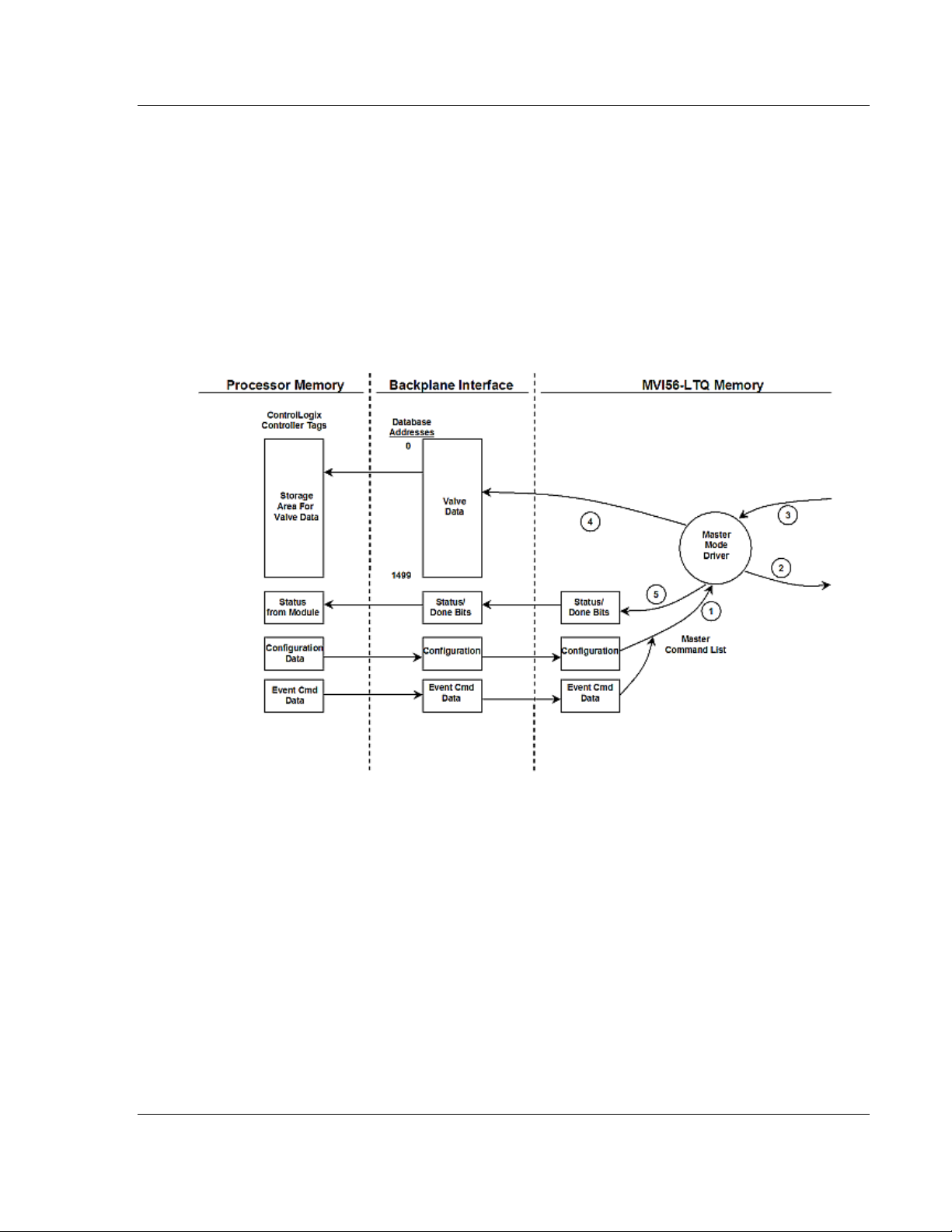
MVI56-LTQ ♦ ControlLogix Platform Reference
Limitorque Valve Actuator Master Communication Module User Manual
5.2.2 Data Flow Between MVI56-LTQ Module and ControlLogix
Processor
The following topics describe the flow of data between the two pieces of
hardware (ControlLinx processor and the MVI56-LTQ module) and nodes on the
Limitorque valve network. In the Master mode, the MVI56-LTQ module is
responsible for issuing read or write commands to slave devices on the
Limitorque valve network. These commands are generated from a fixed set of
commands contained in the module. The module issues the read commands
continuously. Write commands are issued under ladder logic control. The
following flow chart and associated table describe the flow of data into and out of
the module.
1 The module obtains configuration data from the ControlLogix processor. This
configuration completely defines the operation parameters for the module.
2 After configuration, the module begins transmitting read commands to the
valves on the network. If an event command (a bit in one of the digital control
word arrays is set) is recognized by the module, it will issue the associated
write command to the valve. The done bit for the event will be set in the
DoneBit array.
3 Presuming successful processing by the node specified in the command, a
response message is received into the driver for processing.
4 Data received from the node on the network is passed into the module’s
internal database (only for read function messages).
5 Status and done bit array data is returned to the ControlLogix processor.
Refer to Module Configuration (page 21) for a complete description of the
parameters required for configuration of the module.
ProSoft Technology, Inc. Page 67 of 98
August 30, 2010
Page 68
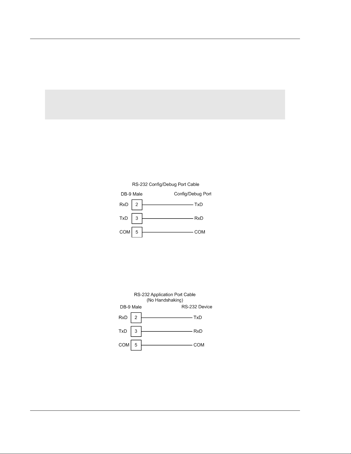
Reference MVI56-LTQ ♦ ControlLogix Platform
User Manual Limitorque Valve Actuator Master Communication Module
5.3 Cable Connections
The application ports on the MVI56-LTQ module support RS-232, RS-422, and
RS-485 interfaces. Please inspect the module to ensure that the jumpers are set
correctly to correspond with the type of interface you are using.
Note: When using RS-232 with radio modem applications, some radios or modems require
hardware handshaking (control and monitoring of modem signal lines). Enable this in the
configuration of the module by setting the UseCTS parameter to 1.
5.3.1 RS-232 Configuration/Debug Port
This port is physically an RJ45 connection. An RJ45 to DB-9 adapter cable is
included with the module. This port permits a PC based terminal emulation
program to view configuration and status data in the module and to control the
module. The cable for communications on this port is shown in the following
diagram:
5.3.2 RS-232 Application Port(s)
When the RS-232 interface is selected, the use of hardware handshaking
(control and monitoring of modem signal lines) is user definable. If no hardware
handshaking will be used, here are the cable pinouts to connect to the port.
Page 68 of 98 ProSoft Technology, Inc.
August 30, 2010
Page 69
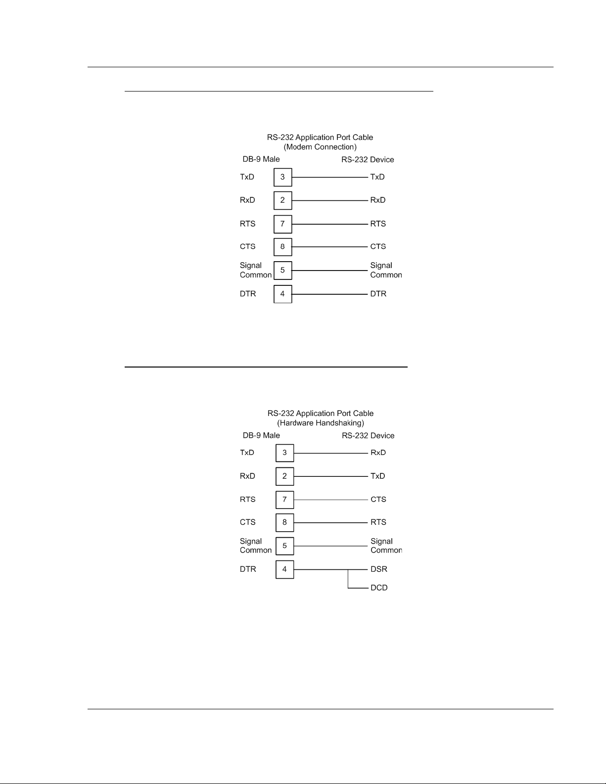
MVI56-LTQ ♦ ControlLogix Platform Reference
Limitorque Valve Actuator Master Communication Module User Manual
RS-232: Modem Connection (Hardware Handshaking Required)
This type of connection is required between the module and a modem or other
communication device.
The "Use CTS Line" parameter for the port configuration should be set to 'Y' for
most modem applications.
RS-232: Null Modem Connection (Hardware Handshaking)
This type of connection is used when the device connected to the module
requires hardware handshaking (control and monitoring of modem signal lines).
ProSoft Technology, Inc. Page 69 of 98
August 30, 2010
Page 70
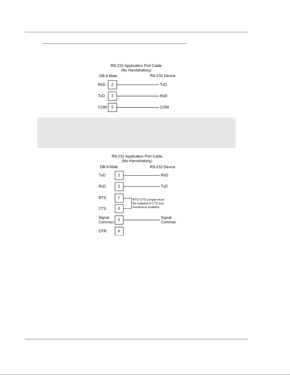
Reference MVI56-LTQ ♦ ControlLogix Platform
User Manual Limitorque Valve Actuator Master Communication Module
RS-232: Null Modem Connection (No Hardware Handshaking)
This type of connection can be used to connect the module to a computer or field
device communication port.
Note: For most null modem connections where hardware handshaking is not required, the Use
CTS Line parameter should be set to N and no jumper will be required between Pins 7 (RTS) and 8
(CTS) on the connector. If the port is configured with the Use CTS Line set to Y, then a jumper is
required between the RTS and the CTS lines on the port connection.
Page 70 of 98 ProSoft Technology, Inc.
August 30, 2010
Page 71
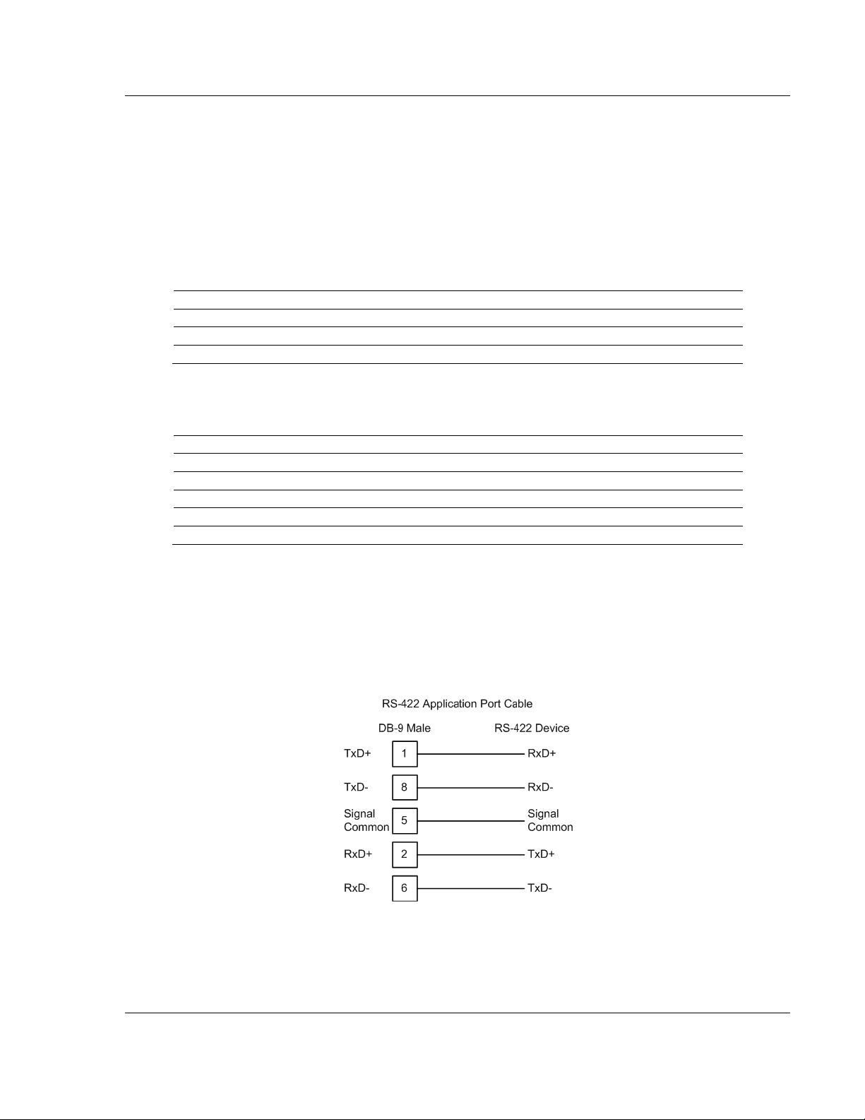
MVI56-LTQ ♦ ControlLogix Platform Reference
Pin
Function
Wire Color
1
Blue
3
Earth ground (see note 2)
Shield
Pin
Function
Wire Color
1
DATA
White
2
3
4
Not Used
Not Used
5
Not Used
Not Used
Limitorque Valve Actuator Master Communication Module User Manual
5.3.3 Network Cable Connection to Limitorque RS-232/RS-485
Converters
For the RS-485 connection, the network cable is connected to the converter via a
three-pin or five-pin removable connector (depending on the converter model).
This connector is located on the rear of the converter. Prepare the cable as
detailed in the Limitorque Accutronix MX/DDC-100 Field Unit Installation and
Operation Manual
Self-Steering Converter – P/N 61-825-1032-4
DATA
2
Note 1: Indicates negative side of signal.
Note 2: Must be connected to earth ground to assure surge protection.
DATA* (see note 1)
Steered Converter – P/N 61-825-0966-4
DATA* (see note 1)
Earth ground (see note 2)
White
Blue
Shield
Note 1: Indicates negative side of signal.
Note 2: Must be connected to earth ground to assure surge protection.
5.3.4 RS-422
The RS-422 interface requires a single four or five wire cable. The Common
connection is optional, depending on the RS-422 network devices used. The
cable required for this interface is shown below:
ProSoft Technology, Inc. Page 71 of 98
August 30, 2010
Page 72
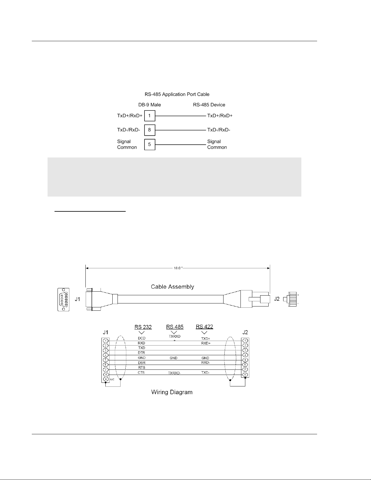
Reference MVI56-LTQ ♦ ControlLogix Platform
User Manual Limitorque Valve Actuator Master Communication Module
5.3.5 RS-485 Application Port(s)
The RS-485 interface requires a single two or three wire cable. The Common
connection is optional, depending on the RS-485 network devices used. The
cable required for this interface is shown below:
Note: Terminating resistors are generally not required on the RS-485 network, unless you are
experiencing communication problems that can be attributed to signal echoes or reflections. In
these cases, installing a 120-ohm terminating resistor between pins 1 and 8 on the module
connector end of the RS-485 line may improve communication quality.
RS-485 and RS-422 Tip
If communication in the RS-422 or RS-485 mode does not work at first, despite
all attempts, try switching termination polarities. Some manufacturers interpret +
and -, or A and B, polarities differently.
5.3.6 DB9 to RJ45 Adaptor (Cable 14)
Page 72 of 98 ProSoft Technology, Inc.
August 30, 2010
Page 73

MVI56-LTQ ♦ ControlLogix Platform Reference
Limitorque Valve Actuator Master Communication Module User Manual
(This page is intentionally left blank.)
ProSoft Technology, Inc. Page 73 of 98
August 30, 2010
Page 74

Reference MVI56-LTQ ♦ ControlLogix Platform
Content
Size
10
Slave #2 data
10
-
-
Slave # 150 data
10
Open command
10
10
Initiate ESD command
10
Terminate ESD Command
10
Reset command
10
Engage Contactor 1 command
10
Disengage Contactor 1 command
10
10
Engage Contactor 3 command
10
Disengage Contactor 3 command
10
Engage Contactor 4 command
10
Disengage Contactor 4 command
10
10
Engage Contactor 6 command
10
Disengage Contactor 6 command
10
Enable Analog command
10
Analog values
150
Done bits
10
10
Last Stop command
10
Last Close command
10
Last Initiate ESD command
10
Last Terminate ESD Command
10
Last Reset command
10
10
Last Engage Contactor 2 command
10
Last Disengage Contactor 2 command
10
Last Engage Contactor 3 command
10
Last Disengage Contactor 3 command
10
10
User Manual Limitorque Valve Actuator Master Communication Module
5.4 MVI56-LT Q Database Definition
This section contains a listing of the internal database of the MVI56-LTQ module.
Registers 0 to 1499 and 2340 to 2349 are transferred from the module to the
processor in blocks 0 to 7. The data in registers 2000 to 2339 is that transferred
in blocks 0 and 1 from the processor to the module.
Register Range
0 to 9
10 to 19
1490 to 1499
2000 to 2009
2010 to 2019
2020 to 2029
2030 to 2039
2040 to 2049
2050 to 2059
2060 to 2069
2070 to 2079
2080 to 2089
2090 to 2099
2100 to 2109
2110 to 2119
2120 to 2129
2130 to 2139
2140 to 2149
2150 to 2159
2160 to 2169
2170 to 2179
2180 to 2189
2190 to 2339
2340 to 2349
2500 to 2509
2510 to 2519
2520 to 2529
2530 to 2539
2540 to 2549
2550 to 2559
2560 to 2569
2570 to 2579
2580 to 2589
2590 to 2599
2600 to 2609
2610 to 2619
2620 to 2629
2630 to 2639
Slave #1 data
Stop command
Close command
Engage Contactor 2 command
Disengage Contactor 2 command
Engage Contactor 5 command
Disengage Contactor 5 command
Last Open command
Last Engage Contactor 1 command
Last Disengage Contactor 1 command
Last Engage Contactor 4 command
Last Disengage Contactor 4 command
10
10
10
10
10
Page 74 of 98 ProSoft Technology, Inc.
August 30, 2010
Page 75

MVI56-LTQ ♦ ControlLogix Platform Reference
Content
Size
10
Last Disengage Contactor 5 command
10
Last Engage Contactor 6 command
10
Last Disengage Contactor 6 command
10
Last Enable Analog command
10
10
Limitorque Valve Actuator Master Communication Module User Manual
Register Range
2640 to 2649
2650 to 2659
2660 to 2669
2670 to 2679
2680 to 2689
2690 to 2839
2840 to 2849
Last Engage Contactor 5 command
Last Analog values
Last Done bits
150
ProSoft Technology, Inc. Page 75 of 98
August 30, 2010
Page 76

Reference MVI56-LTQ ♦ ControlLogix Platform
Offset
Content
Description
212 to 213
Product
These two registers contain the product code of "LTQ5"
Revision
These two registers contain the product version for the current
OpSys
These two registers contain the month and year values for the
Run
These two registers contain the run number value for the
PassCnt
This value is incremented each time a complete program
BTR_Cnt
This field contains the total number of read blocks transferred
BTW_Cnt
This field contains the total number of write blocks transferred
BlkParse
This field contains the total number of blocks successfully
BlkEvent
This field contains the total number of command event blocks
BlkErr
This field contains the total number of block errors recognized
CurSlave
This field contains the index of the current slave being polled
CurPort
This field contains the index of the current port on the module
AltPort
This field is set to 1 when the alternate port (not the primary
SpecPoll
This field contains the value of 0, 1 or 2. A value of 0 indicates
231
State
This field contains the module state machine value.
ComState
This field contains the module communication state machine
CfgErr
This field contains the configuration error status for the
User Manual Limitorque Valve Actuator Master Communication Module
5.5 MVI56-LTQ Status Data Definition
This section contains a description of the members present in the LTQStat
object. This data is transferred from the module to the processor as part of each
read block.
214 to 215
216 to 217
218 to 219
220
221
222
223
224
225
226
227
228
229
230
Queue Number of messages present in the command queue w aiting
running software.
program operating system.
currently running software.
cycle occurs in the module.
for execution.
from the module to the processor.
from the processor to the module.
parsed that were received from the processor.
received from the processor. Each command received by the
module will cause this value to increment.
by the module.
by the module.
being utilized. A value of 0 indicates the first port (Port A). A
value of 1 indicates the second port (Port B) is utilized.
port) is being used due to a communication error.
a normal poll or command is being executed. A value of 1
indicates a special poll for TP_BEFORE_MID_T_HIGH
(register 55) is being executed. A value of 2 indicates a
special poll for registers 6 and 7 is being executed. A value of
3 to 65535 indicates the corresponding register is being
polled.
232
value.
233
module. If an error in the module’s configuration is recognized,
this field will be set to a value other than zero.
Page 76 of 98 ProSoft Technology, Inc.
August 30, 2010
Page 77

MVI56-LTQ ♦ ControlLogix Platform Reference
Member
Name
MX-DDC
UEC-3-DDC
ValvePos
Analog Register
Valve Position (0 - 100%)
Valve Position (0 - 100%)
Status Register
Limitorque Valve Actuator Master Communication Module User Manual
5.6 LTQValve Object Definition
This section describes each member of the LTQValve object of the module
object.
Status
Fault
Bit 00
01
02
03
04
05
06
07
08
09
10
11
12
13
14
15
Fault Register
Bit 00
01
02
03
04
05
06
07
08
09
10
11
12
13
14
15
Opened
Closed
Stopped
Opening
Closing
Valve Jammed
Local Mode Selected
Combined Fault *
Thermal Overload Fault
Future Use
Channel A Fault
Channel B Fault
Open Torque Switch Fault
Close Torque Switch Fault
Manual Operation
Phase Error
Not Used
Not Used
Not Used
Not Used
Phases Missing
Phase Reversed
Not Used
Not Used
Not Used
Not Used
Network ESD is ON **
Local ESD is ON
Unit Reset since last poll
Local Stop Selected
Opening in Local
Closing in Local
Opened
Closed
Stopped
Opening
Closing
Valve Jammed
Local Mode Selected
Combined Fault *
Thermal Overload Fault
Fail De-Energize
Channel A Fault
Channel B Fault
Open Torque Switch Fault
Close Torque Switch Fault
Manual Operation
Phase Error
Open Verify Fault
Close Verify Fault
Open De-Energize Fault
Close De-Energize Fault
Phases Missing
Phase Reversed
Manual Mid to Open
Manual Open to Mid
Manual Mid to Close
Manual Close to Mid
Network ESD is ON**
Local ESD is ON
Unit Reset since last poll
Wrong Rotation
Opening in Local
Closing in Local
ProSoft Technology, Inc. Page 77 of 98
August 30, 2010
* Combined Fault:
Bit 07 of Field Unit Status Register (Word 1) indicates a fault when both bits 10
AND 11, or bit 05, or 08, or 09, or 15 indicate a fault.
** Field unit Net work ESD
Parameter must be configured to Open, Stop, or Close.
Page 78

Reference MVI56-LTQ ♦ ControlLogix Platform
Member
Name
MX-DDC
UEC-3-DDC
Digital Inputs 1
Communication
See Trouble Shooting Section.
Communication
This is a rollover counter (0 to 32767) which increments
User Manual Limitorque Valve Actuator Master Communication Module
DOut
Din1
DIn2
ComStatus
ComCntr
Digital Output
Bit 00
01
02
03
04
05
06
07
08
09
10 to 15
Bit 00
01
02
03
04
05
06
07
08
09
10
11
12
13
14
15
Digital Inputs 2
Bit 00
01
02
03
04
05
06
07
08
09
10
11
12
13
14
15
Status Code
Counter
Close Contactor
Open Contactor
AS-1
AS-2
AS-3
AS-4
AR-1, Opt
AR-2, Opt
AR-3, Opt
Network Relay
Not Used
Remote Mode Selected
Thermal Overload Fault
Open Torque Switch
Open Limit Switch
Close Torque Switch
Close Limit Switch
Not Used
Not Used
User 0, Terminal-21
User 1, Terminal-10
User 2, Terminal-9
User 3, Terminal-6
User 4, Terminal-7
User 5, Terminal-5
User 6, Opt, Terminal-23
User 7, Opt, Terminal-24
Not Used
Not Used
Analog In 1 Lost
Analog In 2 Lost
Network A/B Lost
Not Used
DDC Bd. Present
I/O Opt Board Present
Not Used
Not Used
Not Used
Not Used
Phase Lost
Phase Reverse
User 8, Opt, Terminal-25
Not Used
Do not use this word to determine Slave communication
status. Word N[ ]:1 (Status) bits 10 and 11 are preferred.
This is a module diagnostic word only.
upon completion of every successful commu nic ati on
transaction with a slave. This counter will in crem ent on
poll (read) commands as well as write commands.
Close Contactor
Open Contactor
User (K3)
SW-93 LED
SW-93 LED
User (K6)
N/A
N/A
Bits 08 - 15
Field Unit Software
Version ID
Remote Mode Selected
Thermal Overload Fault
Open Torque Switch
Open Limit Switch
Close Torque Switch
Close Limit Switch
Aux. Open Input
Aux. Close Input
User 0, TB2-1
User 1, TB2-2
User 2, TB2-3
User 3, TB2-4
User 4, TB2-5
User 5, TB2-6
User 6, I/O Module Only
User 7, I/O Module Only
Analog In 1 Lost
Analog In 2 Lost
Analog In 3 Lost
Analog In 4 Lost
Network A/B Lost
Reserved
Reserved
Reserved
Reserved
Reserved
Reserved
Reserved
Phase Lost
Phase Reverse
User 8, I/O Module Only
User 9, I/O Module Only
Page 78 of 98 ProSoft Technology, Inc.
August 30, 2010
Page 79

MVI56-LTQ ♦ ControlLogix Platform Reference
Member
Name
MX-DDC
UEC-3-DDC
Limitorque Valve Actuator Master Communication Module User Manual
SPoll1
SPoll2
Polling (Special)
0
1
2
3 to 65535
Polling (Special)
0
1
2
Unused
TP_BEFORE_MID_T_HIGH Register 55
Analog 1 Register 6
Corresponding register
Unused
Unused
Analog 2 Register 7
For a more complete discussion on register values for Limitorque actuators or I/O
modules, please reference the Limitorque Document #435-23009, available from
Limitorque.
ProSoft Technology, Inc. Page 79 of 98
August 30, 2010
Page 80

Reference MVI56-LTQ ♦ ControlLogix Platform
LTQ Commands
MX-DDC
UEC-3-DDC
I/O Module
Open
Yes
Yes
Do Not Use
Stop
Yes
Yes
Do Not Use
Close
Yes
Yes
Do Not Use
Start Network ESD
Yes
Yes
Do Not Use
Stop Network ESD
Engage Relay #1
Yes (AS-1)
Do Not Use
Yes (K2)
Engage Relay #2
Yes (AS-2)
Do Not Use
Yes (K1)
Engage Relay #3
Yes (AS-3)
Yes (K3)
Yes (K3)
Engage Relay #4
Yes (AS-4)
Do Not Use
Yes (K4)
Engage Relay #5
Engage Relay #6
Yes (K2)
Disengage Relay #2
Yes (AS-2)
Do Not Use
Yes (K1)
Disengage Relay #3
Yes (AS-3)
Yes (K3)
Yes (K3)
Disengage Relay #4
Yes (AS-4)
Do Not Use
Yes (K4)
Disengage Relay #5
Yes (AR-1)
Do Not Use
Yes (K5)
Disengage Relay #6
User Manual Limitorque Valve Actuator Master Communication Module
5.7 Command Usage for Limitorque Products
This topic describes the commands supported in the MVI56-LTQ module and
their association with different Limitorque interfaces.
Yes Yes
Reset
Yes (AR-1) Do Not Use
Yes (AR-2) Yes (K6)
Disengage Relay #1
Yes (AS-1) Do Not Use
Do Not Use
Yes (K5)
Yes (K6)
Yes (AR-2) Yes (K6)
Send Valve Position
Enable Valve Position
Yes (K6)
Page 80 of 98 ProSoft Technology, Inc.
August 30, 2010
Page 81

MVI56-LTQ ♦ ControlLogix Platform Reference
Modbus
Code
Register
Count or
Value
Description
Stop Command
6
40001
512
Disengages Open or Close
6
40001
1280
Initiates Network ESD function in the
6
40001
1536
Terminates Network ESD function in
Reset
6
40001
1024
6
40001
2304
Engages Relay #2 (I/O Module)
6
40001
2560
Engages Relay #1 (I/O Module)
6
40001
3072
Engages Relay #4 (I/O Module)
6
40001
3328
Engages Relay #5 (I/O Module)
6
40001
3584
Engages Relay #6
6
40001
4352
Disengages Relay #2 (I/O Module)
6
40001
4864
Disengages Relay #3
6
40001
5120
Disengages Relay #4 (I/O Module)
6
40001
5376
Disengages Relay #5 (I/O Module)
6
40001
5632
Disengages Relay #6
Value
Position Value
3
40055
1
Command is executed automatically if
3
40006
2
Command is executed automatically if
Limitorque Valve Actuator Master Communication Module User Manual
The ProSoft Technology LTQ Master Module is pre-programmed to support a
subset of the Modbus protocol. The commands are hard coded into the module
and have been selected to implement specific functionality. The programmed
commands are documented in the following table.
Command
Function
Poll Slave
Open Command
Close Command
Start Network ESD
Stop Network ESD
Engage Relay #1
Engage Relay #2
Engage Relay #3
Engage Relay #4
Engage Relay #5
Engage Relay #6
Disengage Relay #1
Disengage Relay #2
Disengage Relay #3
Disengage Relay #4
Disengage Relay #5
Disengage Relay #6
Send Valve Position
Enable Valve
Function
Address
Write
3 40008 6 Command is executed automatically to
any slave in the Active Slave Table
6 40001 256 Open Command (Interlocked with
Close Command in the slave)
6 40001 768 Close Command (Interlocked with
Open Command in the slave)
addressed slave
the addressed slave
Engages AS-1 (MX-DDC)
Engages AS-2 (MX-DDC)
6 40001 2816 Engages Relay #3
Engages AS-3 (MX-DDC)
Engages AS-4 (MX-DDC)
Engages AR-1 (MX-DDC)
Engages AR-2 (MX-DDC)
Disengages AS-1 (MX-DDC)
6 40001 4608 Disengages Relay #1 (I/O Module)
Disengages AS-2 (MX-DDC)
Disengages AS-3 (MX-DDC)
Disengages AS-4 (MX-DDC)
Disengages AR-1 (MX-DDC)
Disengages AR-2 (MX-DDC)
6 40002 Value from
PLC
6 40001 6656
Position to move actuator
0 to 100% of Open
Move-To (enable)
Poll Slave Special 1
Poll Slave Special 2
ProSoft Technology, Inc. Page 81 of 98
August 30, 2010
Special Polling is set to 1
Special Polling is set to 2
Page 82

Reference MVI56-LTQ ♦ ControlLogix Platform
User Manual Limitorque Valve Actuator Master Communication Module
5.8 Polling Schemes
In Looped Mode, the LTQ provides communication redundancy to each
configured slave on the network. The LTQ monitors the health of each
communication path between port 1 and each configured slave and between port
2 and each configured slave. LTQ port 1 communication status between port 1
and the addressed slave is recorded in the slave Channel A status bit. LTQ port
2 communication status between port 2 and the addressed slave is recorded in
the slave Channel B status bit. Both Channel A and Channel B status bits are
located in the slave Status register, bits 10 and 11(Word 1, bits 10 and 11).
On a healthy network where all configured slaves are communicating; the LTQ
will first poll all slaves via port 1, then poll all slaves via port 2, back to port 1, and
so on. As each slave is successfully polled, the respective Channel bit is set to 0
in the slave Status register. Remember the LTQ port 1 equals Channel A and the
LTQ port 2 equals Channel B.
Should a slave not be reached on a poll, the LTQ will set the corresponding
Channel Fail bit to 1, switch to the other port and attempt to communicate with
the same slave. Should the slave not communicate from the second port, the
corresponding Channel Fail bit will be set to 1, and the LTQ will resume polling
on the original port. After the LTQ has completed polling all configured slaves on
the first port, the polling routine will switch to the other port and repeat the above
process.
Example:
There are 5 slaves on the network and slave number 3 has been turned off. The
LTQ is currently polling the slaves through the LTQ port 1 (Channel A). Slave
number 1 and 2 respond to the LTQ port 1 poll. Slave number 3 does not
respond to the port 1 poll causing the LTQ to set slave 3 Channel A bit to 1. The
LTQ now changes to port 2 (Channel B) and polls slave number 3. Slave number
3 does not respond to the port 2 poll causing the LTQ to set the slave 3 Channel
B bit to 1. Next the LTQ changes back to port 1 and attempts to poll slave
number 4. This communication attempt is successful and the LTQ now polls
slave number 5 through the LTQ port 1. Slave number 5 responds completing the
port 1 poll.
Next the LTQ repeats the process through port 2 (Channel B). Slave 1 and 2
respond, slave 3 does not respond and the LTQ sets the slave 3 Channel B bit to
1. The LTQ changes to port 1 (Channel A) and attempts to communicate with
slave 3. Slave 3 does not respond, the LTQ sets the slave 3 Channel A bit to 1,
switches back to port 2 and resumes polling the remainder of the configured
slaves. Once slaves 4 and 5 have been successfully polled via port 2, the LTQ
then switches to port 1 and repeats the polling process. The port alternation
process described above continues until slave 3 is powered on and the
communication fault clears.
Commands for slave control interrupt the polling process and are issued through
the current poll port. After the slave has acknowledged the command, the LTQ
resumes the polling process. In the event of a communication fault between the
current poll port and a commanded slave, the LTQ will issue the command
through the other communication port.
Page 82 of 98 ProSoft Technology, Inc.
August 30, 2010
Page 83

MVI56-LTQ ♦ ControlLogix Platform Reference
Example 1
Example 2
Example 3
Example 4
Slave #
1
2
0 0 0 0 0 1 0
1
3
0 0 1 1 0 1 0
1
4
0 0 0 0 1 0 0
1 5 0 0 0 0 1 0 0
1
Example 5
Example 6
Example 7
Slave #
Ch. A
Ch. B
Ch. A
Ch. B
Ch. A
Ch. B
1
0 0 0 0 0
0
2
3
0
4
0 0 0 0 1
0
5
0 0 0 0 1
0
Limitorque Valve Actuator Master Communication Module User Manual
Looped Network Truth Table
(Recorded in Slave Status Register Bit 10 and 11)
Ch. A Ch. B Ch. A Ch. B Ch . A Ch. B Ch. A
0 0 0 0 0 1 0
Ch. B
1
Example 1:
The LTQ is successfully communicating to each slave and sets the bits equating
to Channel A and B to 0. A value of 0 in the Channel A and B status indicate
successful communication.
Example 2:
The LTQ is successfully communicating to slaves 1, 2, 4, and 5 via both ports.
Slave number 3 is without power causing the slave 3 network board bypass
relays to de-energize. This de-energizing of the bypass relays shorts the signal
through the network board and isolates the slave from the DDC-100 network.
Example 3:
The LTQ is successfully communicating to slaves 1, 2, 3 via port 1 and 4, 5 via
port 2. When a slave does not communicate within a predetermined time-out
period the LTQ sets the corresponding Channel bit to a value of 1. This example
indicates a wiring problem between slave 3 & 4. This problem is typically a cable
breakage, short, or improperly terminated wire.
Example 4:
The LTQ is attempting to communicate to the slaves via both ports but is unable
to reach any slaves via port 2. This typically indicates a broken cable connection
at port 2 or at the first slave from port 2, broken or shorted cable between the
LTQ and the first slave from port 2, improperly terminated wires, or loss of power
to the RS-232/485 converter if attached to the LTQ port 2.
Non-Looped Network Truth Table via Port 1 Polling Only
(Recorded in Slave Status Register Bit 10, Bit 11 Channel B is always 0)
0 0 1 0 0
0 0 0 0 1
0
ProSoft Technology, Inc. Page 83 of 98
August 30, 2010
Page 84

Reference MVI56-LTQ ♦ ControlLogix Platform
User Manual Limitorque Valve Actuator Master Communication Module
Example 5:
The LTQ is successfully communicating to each slave and sets the bits equating
to Channel A to 0. A value of 0 in the Channel A status indicates successful
communication.
Example 6:
The LTQ is successfully communicating to slave 1, 3, 4, and 5. Slave 2 does not
respond causing the LTQ to set slave 2 Status register bit 10 to 1. In this
example, slave 2 is without power causing the slave 2 network board bypass
relays to de-energize. This de-energizing of the bypass relays shorts the signal
through the network board and isolates the slave from the DDC-100 network.
Example 7:
The LTQ is successfully communicating to slaves 1 and 2 but is not able to
communicate to slaves 3, 4, and 5 causing the LTQ to set slave 3, 4, 5 Status
register bit 10 to 1. This typically indicates a broken or shorted cable between
slave 2 and 3, a broken cable connection at slave 2 or 3, improperly terminated
wires at slave 2 or 3, or loss of power to slaves 3, 4, and 5.
Page 84 of 98 ProSoft Technology, Inc.
August 30, 2010
Page 85
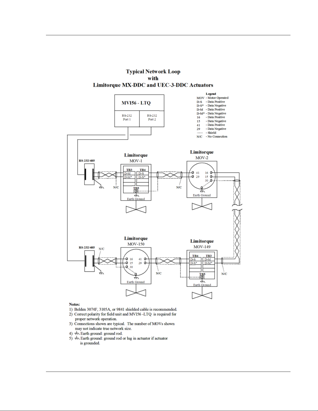
MVI56-LTQ ♦ ControlLogix Platform Reference
Limitorque Valve Actuator Master Communication Module User Manual
5.9 Typical Network Loop
The following example shows an example of a network loop with Limitorque MXDDC and UEC-DDC actuators.
ProSoft Technology, Inc. Page 85 of 98
August 30, 2010
Page 86

Reference MVI56-LTQ ♦ ControlLogix Platform
User Manual Limitorque Valve Actuator Master Communication Module
Page 86 of 98 ProSoft Technology, Inc.
August 30, 2010
Page 87

MVI56-LTQ ♦ ControlLogix Platform Support, Service & Warranty
Web Site: www.prosoft-technology.com/support
(location in Malaysia)
Tel: +603.7724.2080, E-mail: asiapc@prosoft-technology.com
(location in China)
France)
Tel: +971-4-214-6911,
Languages spoken include: English, Spanish
Limitorque Valve Actuator Master Communication Module User Manual
6 Support, Service & Warranty
In This Chapter
How to Contact Us: Technical Support
Return Material Authorization (RMA) Policies and Conditions ............... 89
LIMITED WARRANTY ........................................................................... 91
.................................................. 87
How to Contact Us: Technical Support
ProSoft Technology, Inc. (ProSoft) is committed to providing the most efficient
and effective support possible. Before calling, please gather the following
information to assist in expediting this process:
1 Product Version Number
2 System architecture
3 Network details
If the issue is hardware related, we will also need information regarding:
1 Module configuration and associated ladder files, if any
2 Module operation and any unusual behavior
3 Configuration/Debug status information
4 LED patterns
5 Details about the serial, Ethernet or fieldbus devices interfaced to the module,
if any.
Note: For technical support calls within the United States, an after-hours answering system allows
24-hour/7-days-a-week pager access to one of our qualified Technical and/or Application Support
Engineers.
Internet
Asia Pacific
Asia Pacific
Europe
(location in Toulouse,
Europe
(location in Dubai, UAE)
North America
(location in California)
E-mail address: support@prosof t-technology.com
Languages spoken include: Chinese, English
Tel: +86.21.5187.7337 x888, E-mail: asiapc@prosoft-technology.com
Languages spoken include: Chinese, English
Tel: +33 (0) 5.34.36.87.20,
E-mail: support.EMEA@prosoft-technology.com
Languages spoken include: French, English
E-mail: mea@prosoft-technology.com
Languages spoken include: English, Hindi
Tel: +1.661.716.5100,
E-mail: support@prosoft-technology.com
ProSoft Technology, Inc. Page 87 of 98
August 30, 2010
Page 88

Support, Service & Warranty MVI56-LTQ ♦ ControlLogix Platform
Tel: +52-222-3-99-6565,
Languages spoken include: Portuguese, English
User Manual Limitorque Valve Actuator Master Communication Module
Latin America
(Oficina Regional)
Latin America
(location in Puebla, Mexico)
Brasil
(location in Sao Paulo)
Tel: +1-281-2989109,
E-Mail: latinam@prosoft-technology.com
Languages spoken include: Spanish, English
E-mail: soporte@prosoft-technology.com
Languages spoken include: Spanish
Tel: +55-11-5083-3776,
E-mail: br asil@prosoft-technology.com
Page 88 of 98 ProSoft Technology, Inc.
August 30, 2010
Page 89

MVI56-LTQ ♦ ControlLogix Platform Support, Service & Warranty
Limitorque Valve Actuator Master Communication Module User Manual
6.1 Return Material Authorization (RMA) Policies and Conditions
The following RMA Policies and Conditions (collectively, "RMA Policies") apply to
any returned Product. These RMA Policies are subject to change by ProSoft
without notice. For warranty information, see Limited Warranty (page 91). In the
event of any inconsistency between the RMA Policies and the Warranty, the
Warranty shall govern.
6.1.1 All Product Returns:
a) In order to return a Product for repair, exchange or otherwise, the
Customer must obtain a Return Material Authorization (RMA) number
from ProSoft and comply with ProSoft shipping instructions.
b) In the event that the Customer experiences a problem with the Product for
any reason, Customer should contact ProSoft Technical Support at one of
the telephone numbers listed above (page 87). A Technical Support
Engineer will request that you perform several tests in an attempt to
isolate the problem. If after completing these tests, the Product is found to
be the source of the problem, we will issue an RMA.
c) All retur ned Products must be shipped freight prepaid, in the original
shipping container or equivalent, to the location specified by ProSoft, and
be accompanied by proof of purchase and receipt date. The RMA number
is to be prominently marked on the outside of the shipping box. Customer
agrees to insure the Product or assume the risk of loss or damage in
transit. Products shipped to ProSoft using a shipment method other than
that specified by ProSoft, or shipped without an RMA number will be
returned to the Customer, freight collect. Contact ProSoft Technical
Support for further information.
d) A 10% restocking fee applies to all warranty credit returns, whereby a
Customer has an application change, ordered too many, does not need,
etc. Returns for credit require that all accessory parts included in the
original box (i.e.; antennas, cables) be returned. Failure to return these
items will result in a deduction from the total credit due for each missing
item.
ProSoft Technology, Inc. Page 89 of 98
August 30, 2010
Page 90

Support, Service & Warranty MVI56-LTQ ♦ ControlLogix Platform
User Manual Limitorque Valve Actuator Master Communication Module
6.1.2 Procedures for Return of Units Under Warranty:
A Technical Support Engineer must approve the return of Product under
ProSoft’s Warranty:
a) A replacement module will be shipped and invoiced. A purchase order will
be required.
b) Credit for a product under warranty will be issued upon receipt of
authorized product by ProSoft at designated location referenced on the
Return Material Authorization
i. If a defect is found and is determined to be customer generated, or if
the defect is otherwise not covered by ProSoft’s warranty, there will
be no credit given. Customer will be contacted and can request
module be returned at their expense;
ii. If defect is customer generated and is repairable, customer can
authorize ProSoft repair the unit by providing a purchase order for
30% of the current list price plus freight charges, duties and taxes as
applicable.
6.1.3 Procedures for Return of Units Out of Warranty:
a) Customer sends unit in for evaluation to location specified by ProSoft,
freight prepaid.
b) If no defect is found, Customer will be charged the equivalent of $100
USD, plus freight charges, duties and taxes as applicable. A new
purchase order will be required.
c) If unit is repaired, charge to Customer will be 30% of current list price
(USD) plus freight charges, duties and taxes as applicable. A new
purchase order will be required or authorization to use the purchase order
submitted for evaluation fee.
The following is a list of non-repairable units:
o 3150 - All
o 3750
o 3600 - All
o 3700
o 3170 - All
o 3250
o 1560 - Can be repaired, only if defect is the power supply
o 1550 - Can be repaired, only if defect is the power supply
o 3350
o 3300
o 1500 - All
Page 90 of 98 ProSoft Technology, Inc.
August 30, 2010
Page 91

MVI56-LTQ ♦ ControlLogix Platform Support, Service & Warranty
Limitorque Valve Actuator Master Communication Module User Manual
6.2 LIMITED WARRANTY
This Limited Warranty ("Warranty") governs all sales of hardware, software and
other products (collectively, "Product") manufactured and/or offered for sale by
ProSoft, and all related services provided by ProSoft, including maintenance,
repair, warranty exchange, and service programs (collectively, "Services"). By
purchasing or using the Product or Services, the individual or entity purchasing or
using the Product or Services ("Customer") agrees to all of the terms and
provisions (collectively, the "Terms") of this Limited Warranty. All sales of
software or other intellectual property are, in addition, subject to any license
agreement accompanying such software or other intellectual property.
6.2.1 What Is Covered By This Warranty
a) Warranty On New Product s: ProSoft warrants, to the original purchaser,
that the Product that is the subject of the sale will (1) conform to a nd
perform in accordance with published specifications prepared, approved
and issued by ProSoft, and (2) will be free from defects in material or
workmanship; provided these warranties only cover Product that is sold as
new. This Warranty expires three (3) years from the date of shipment for
Product purchased on or after January 1st, 2008, or one (1) year from the
date of shipment for Product purchased before January 1st, 2008 (the
"Warranty Period"). If the Customer discovers within the Warranty Period
a failure of the Product to conform to specifications, or a defect in material
or workmanship of the Product, the Customer must promptly notify
ProSoft by fax, email or telephone. In no event may that notification be
received by ProSoft later than 39 months from date of original shipment.
Within a reasonable time after notification, ProSoft will correct any failure
of the Product to conform to specifications or any defect in material or
workmanship of the Product, with either new or remanufactured
replacement parts. ProSoft reserves the right, and at its sole discretion,
may replace unrepairable units with new or remanufactured equipment.
All replacement units will be covered under warranty for the 3 year period
commencing from the date of original equipment purchase, not the date of
shipment of the replacement unit. Such repair, including both parts and
labor, will be performed at ProSoft’s expense. All warranty service will be
performed at service centers designated by ProSoft.
b) Warranty On Services: Materials and labor performed by ProSoft to repair
a verified malfunction or defect are warranteed in the terms specified
above for new Product, provided said warranty will be for the period
remaining on the original new equipment warranty or, if the original
warranty is no longer in effect, for a period of 90 days from the date of
repair.
ProSoft Technology, Inc. Page 91 of 98
August 30, 2010
Page 92

Support, Service & Warranty MVI56-LTQ ♦ ControlLogix Platform
User Manual Limitorque Valve Actuator Master Communication Module
6.2.2 What Is Not Covered By This Warranty
a) ProSoft makes no representation or warranty, expressed or implied, that
the operation of software purchased from ProSoft will be uninterrupted or
error free or that the functions contained in the software will meet or
satisfy the purchaser’s intended use or requirements; the Customer
assumes complete responsibility for decisions made or actions taken
based on information obtained using ProSoft software.
b) This Warranty does not cover the failure of the Product to perform
specified functions, or any other non-conformance, defects, losses or
damages caused by or attributable to any of the following: (i) shipping; (ii)
improper installation or other failure of Customer to adhere to ProSoft’s
specifications or instructions; (iii) unauthorized repair or maintenance; (iv)
attachments, equipment, options, parts, software, or user-created
programming (including, but not limited to, programs developed with any
IEC 61131-3, "C" or any variant of "C" programming languages) not
furnished by ProSoft; (v) use of the Product for purposes other than those
for which it was designed; (vi) any other abuse, misapplication, neglect or
misuse by the Customer; (vii) accident, improper testing or causes
external to the Product such as, but not limited to, exposure to extremes
of temperature or humidity, power failure or power surges; or (viii)
disasters such as fire, flood, earthquake, wind and lightning.
c) T he information in this Agreement is subject to change without notice.
ProSoft shall not be liable for technical or editorial errors or omissions
made herein; nor for incidental or consequential damages resulting from
the furnishing, performance or use of this material. The user guide
included with your original product purchase from ProSoft contains
information protected by copyright. No part of the guide may be duplicated
or reproduced in any form without prior written consent from ProSoft.
6.2.3 Disclaimer Regarding High Risk Activities
Product manufactured or supplied by ProSoft is not fault tolerant and is not
designed, manufactured or intended for use in hazardous environments requiring
fail-safe performance including and without limitation: the operation of nuclear
facilities, aircraft navigation of communication systems, air traffic control, direct
life support machines or weapons systems in which the failure of the product
could lead directly or indirectly to death, personal injury or severe physical or
environmental damage (collectively, "high risk activities"). ProSoft specifically
disclaims any express or implied warranty of fitness for high risk activities.
Page 92 of 98 ProSoft Technology, Inc.
August 30, 2010
Page 93

MVI56-LTQ ♦ ControlLogix Platform Support, Service & Warranty
Limitorque Valve Actuator Master Communication Module User Manual
6.2.4 Intellectual Property Indemnity
Buyer shall indemnify and hold harmless ProSoft and its employees from and
against all liabilities, losses, claims, costs and expenses (including attorney’s
fees and expenses) related to any claim, investigation, litigation or proceeding
(whether or not ProSoft is a party) which arises or is alleged to arise from Buyer’s
acts or omissions under these Terms or in any way with respect to the Products.
Without limiting the foregoing, Buyer (at its own expense) shall indemnify and
hold harmless ProSoft and defend or settle any action brought against such
Companies to the extent based on a claim that any Product made to Buyer
specifications infringed intellectual property rights of another party. ProSoft
makes no warranty that the product is or will be delivered free of any person’s
claiming of patent, trademark, or similar infringement. The Buyer assumes all
risks (including the risk of suit) that the product or any use of the product will
infringe existing or subsequently issued patents, trademarks, or copyrights.
a) Any documentation included with Product purchased from ProSoft is
protected by copyright and may not be duplicated or reproduced in any
form without prior written consent from ProSoft.
b) ProSoft’s technical specifications and documentation that are included
with the Product are subject to editing and modification without notice.
c) T r ansfer of title shall not operate to convey to Customer any right to make,
or have made, any Product supplied by ProSoft.
d) Customer is granted no right or license to use any software or other
intellectual property in any manner or for any purpose not expressly
permitted by any license agreement accompanying such software or other
intellectual property.
e) Customer agrees that it shall not, and shall not authorize others to, copy
software provided by ProSoft (except as expressly permitted in any
license agreement accompanying such software); transfer software to a
third party separately from the Product; modify, alter, translate, decode,
decompile, disassemble, reverse-engineer or otherwise attempt to derive
the source code of the software or create derivative works based on the
software; export the software or underlying technology in contravention of
applicable US and international export laws and regulations; or use the
software other than as authorized in connection with use of Product.
f) Additional Restrictions Relating To Software And Other Intellectual
Property
In addition to compliance with the Terms of this Warranty, Customers
purchasing software or other intellectual property shall comply with any
license agreement accompanying such software or other intellectual
property. Failure to do so may void this Warranty with respect to such
software and/or other intellectual property.
6.2.5 Disclaimer of all Other Warranties
The War ranty set forth in What Is Covered By This Warranty (page 91) are in lieu
of all other warranties, express or implied, including but not limited to the implied
warranties of merchantability and fitness for a particular purpose.
ProSoft Technology, Inc. Page 93 of 98
August 30, 2010
Page 94

Support, Service & Warranty MVI56-LTQ ♦ ControlLogix Platform
User Manual Limitorque Valve Actuator Master Communication Module
6.2.6 Limitation of Remedies **
In no event will ProSoft or its Dealer be liable for any special, incidental or
consequential damages based on breach of warranty, breach of contract,
negligence, strict tort or any other legal theory. Damages that ProSoft or its
Dealer will not be responsible for include, but are not limited to: Loss of profits;
loss of savings or revenue; loss of use of the product or any associated
equipment; loss of data; cost of capital; cost of any substitute equipment,
facilities, or services; downtime; the claims of third parties including, customers of
the Purchaser; and, injury to property.
** Some areas do not allow time limitations on an implied warranty, or allow the exclusion or
limitation of incidental or consequential damages. In such areas, the above limitations may not
apply. This Warranty gives you specific legal rights, and you may also have other rights which vary
from place to place.
6.2.7 Time Limit for Bringing Suit
Any action for breach of warranty must be commenced within 39 months
following shipment of the Product.
6.2.8 No Other Warranties
Unless modified in writing and signed by both parties, this Warranty is
understood to be the complete and exclusive agreement between the parties,
suspending all oral or written prior agreements and all other communications
between the parties relating to the subject matter of this Warranty, including
statements made by salesperson. No employee of ProSoft or any other party is
authorized to make any warranty in addition to those made in this Warranty. The
Customer is warned, therefore, to check this Warranty carefully to see that it
correctly reflects those terms that are important to the Customer.
6.2.9 Allocation of Risks
This Warranty allocates the risk of product failure between ProSoft and the
Customer. This allocation is recognized by both parties and is reflected in the
price of the goods. The Customer acknowledges that it has read this Warranty,
understands it, and is bound by its Terms.
Page 94 of 98 ProSoft Technology, Inc.
August 30, 2010
Page 95

MVI56-LTQ ♦ ControlLogix Platform Support, Service & Warranty
Limitorque Valve Actuator Master Communication Module User Manual
6.2.10 Control ling Law and Severability
This Warranty shall be governed by and construed in accordance with the laws of
the United States and the domestic laws of the State of California, without
reference to its conflicts of law provisions. If for any reason a court of competent
jurisdiction finds any provisions of this Warranty, or a portion thereof, to be
unenforceable, that provision shall be enforced to the maximum extent
permissible and the remainder of this Warranty shall remain in full force and
effect. Any cause of action with respect to the Product or Services must be
instituted in a court of competent jurisdiction in the State of California.
ProSoft Technology, Inc. Page 95 of 98
August 30, 2010
Page 96

Support, Service & Warranty MVI56-LTQ ♦ ControlLogix Platform
User Manual Limitorque Valve Actuator Master Communication Module
Page 96 of 98 ProSoft Technology, Inc.
August 30, 2010
Page 97

MVI56-LTQ ♦ ControlLogix Platform Index
Limitorque Valve Actuator Master Communication Module User Manual
F
Functional Overview • 9, 58
Functional Specifications • 57
Index
G
A
ActiveSlaves • 27
Adding the Module to an Existing Project • 34
All Product Returns: • 89
Allocation of Risks • 94
Analyzing Data for the first application port • 47
Analyzing Data for the second application port • 47
B
Backplane Data Transfer • 58
Battery Life Advisory • 4
BaudRate • 23
BlkDelay • 24
BlkFailCnt • 26
BTRMax • 23
C
Cable Connections • 68
Clearing a Fault Condition • 39
Command Control Blocks • 66
Command Usage for Limitorque Products • 80
Communication Error Codes • 41
Configuration Data • 22, 23
Configuration Data Transfer • 65
Configuration Object (LTQCfg) • 22
Configuring the MVI56-LTQ Module • 21, 67
Configuring the RSLinx Driver for the PC COM Port •
17
Connect your PC to the Module • 20
Connecting Your PC to the ControlLogix Processor •
16
Controlling Law and Severability • 95
ControlLogix Processor Not in Run • 58
D
Data Analyzer • 45, 47
Data Analyzer Tips • 49
Data Flow Between MVI56-LTQ Module and
ControlLogix Processor • 67
Database View Menu • 46, 52
DB9 to RJ45 Adaptor (Cable 14) • 72
Diagnostics and Troubleshooting • 9, 37
Disclaimer of all Other Warranties • 93
Disclaimer Regarding High Risk Activities • 92
Displaying the Current Page of Registers Again • 52
Displaying Timing Marks in the Data Analyzer • 48
Downloading the Sample Program to the Processor •
19
E
General Concepts • 58
General Specifications • 55
Guide to the MVI56-LTQ User Manual • 9
H
Hardware Specifications • 55
How to Contact Us
Technical Support • 87, 89
I
Important Installation Instructions • 3
Installing the Module in the Rack • 15
Intellectual Property Indemnity • 93
K
Keystrokes • 44
L
Ladder Logic • 29
LastState • 24
LED Status Indicators • 38
Limitation of Remedies ** • 94
LIMITED WARRANTY • 89, 91
LTQValve Object Definition • 77
M
Main Menu • 45
MaxSlaves • 23
Module Data Object (LTQModuleDef) • 30
Moving Back Through 5 Pages of Registers • 53
Moving Forward Through 5 Pages of Registers • 53
MsgRespTm • 23
MVI (Multi Vendor Interface) Modules • 3
MVI56-LTQ Database Definition • 74
MVI56-LTQ Status Data Definition • 31, 76
N
Navigation • 44
NetPoll • 24
Network Cable Connection to Limitorque RS-232/RS-
485 Converters • 71
No Other Warranties • 94
Normal Data Transfer • 61
O
Opening the Data Analyzer Menu • 45
Opening the Database View Menu • 46
Opening the Sample Ladder Logic • 17
Opening the Valve Data menu • 46
Exiting the Program • 47
ProSoft Technology, Inc. Page 97 of 98
August 30, 2010
Page 98

Index MVI56-LTQ ♦ ControlLogix Platform
User Manual Limitorque Valve Actuator Master Communication Module
P
Package Contents • 13
Pinouts • 3, 14, 68, 72, 82
Polling Schemes • 82
Procedures for Return of Units Out of Warranty: • 90
Procedures for Return of Units Under Warranty: • 90
Product Specifications • 9, 55
PropDelay • 25
ProSoft Technology® Product Documentation • 2
R
Reading Status Data from the Module • 43
Redisplaying the Current Page • 54
Reference • 9, 55
Reference Documents • 21
Removing Timing Marks in the Data Analyzer • 48
Required Software • 43
Return Material Authorization (RMA) Policies and
Conditions • 89
Returning to the Main Menu • 49, 53, 54
RS-232
Modem Connection (Hardware Handshaki ng
Required) • 69
Null Modem Connection (Hardware Handshaking)
• 69
Null Modem Connection (No Hardware
Handshaking) • 70
RS-232 Application Port(s) • 68
RS-232 Configuration/Debug Port • 68
RS-422 • 71
RS-485 and RS-422 Tip • 72
RS-485 Application Port(s) • 72
RTSOn • 25
Viewing Block Transfer Statistics • 45
Viewing Data in ASCII (Text) Format • 48, 53
Viewing Data in Decimal Format • 9, 53
Viewing Data in Floating-Point Format • 53
Viewing Data in Hexadecimal Format • 48, 53
Viewing Module Configuration • 46
Viewing Module Status • 46
Viewing Register Pages • 52
Viewing the Next 100 Registers of Data • 53
Viewing the Next Page of Data • 54
Viewing the Previous 100 Registers of Data • 53
Viewing the Previous Page of Data • 54
Viewing Valve Registers • 54
Viewing Version Information • 46
W
Warm Booting the Module • 46
Warnings • 3
What Is Covered By This Warranty • 91, 93
What Is Not Covered By This Warranty • 92
Y
Your Feedback Please • 2
S
Setting Jumpers • 14
SpecPolling • 26
Start Here • 9, 11
Starting the Data Analyzer • 48
Status Object (LTQStat) • 31
Stopping the Data Analyzer • 49
Support, Service & Warranty • 9, 87
System Requirements • 12
T
The Configuration/Debug Menu • 44
Time Limit for Bringing Suit • 94
Troubleshooting • 40
Typical Network Loop • 85
U
Use_CTS • 26
User Data Objects • 32
Using the Configuration/Debug Port • 42
V
Valve Data Menu • 54
Page 98 of 98 ProSoft Technology, Inc.
August 30, 2010
 Loading...