

Page 1

MVI56E-MNETC
ControlLogix Platform
Modbus TCP/IP Client Enhanced
Communication Module
February 3, 2013
USER MANUAL
Page 2

Your Feedback Please
We always want you to feel that you made the right decision to use our products. If you have suggestions, comments,
compliments or complaints about our products, documentation, or support, please write or call us.
How to Contact Us
ProSoft Technology
5201 Truxtun Ave., 3rd Floor
Bakersfield, CA 93309
+1 (661) 716-5100
+1 (661) 716-5101 (Fax)
www.prosoft-technology.com
support@prosoft-technology.com
Copyright © 2013 ProSoft Technology, Inc., all rights reserved.
MVI56E-MNETC User Manual
February 3, 2013
ProSoft Technology ®, ProLinx ®, inRAx ®, ProTalk ®, and RadioLinx ® are Registered Trademarks of ProSoft
Technology, Inc. All other brand or product names are or may be trademarks of, and are used to identify products
and services of, their respective owners.
In an effort to conserve paper, ProSoft Technology no longer includes printed manuals with our product shipments.
User Manuals, Datasheets, Sample Ladder Files, and Configuration Files are provided on the enclosed DVD, and are
available at no charge from our web site: http://www.prosoft-technology.com/
Content Disclaimer
This documentation is not intended as a substitute for and is not to be used for determining suitability or reliability of
these products for specific user applications. It is the duty of any such user or integrator to perform the appropriate
and complete risk analysis, evaluation and testing of the products with respect to the relevant specific application or
use thereof. Neither ProSoft Technology nor any of its affiliates or subsidiaries shall be responsible or liable for
misuse of the information contained herein. Information in this document including illustrations, specifications and
dimensions may contain technical inaccuracies or typographical errors. ProSoft Technology makes no warranty or
representation as to its accuracy and assumes no liability for and reserves the right to correct such inaccuracies or
errors at any time without notice. If you have any suggestions for improvements or amendments or have found errors
in this publication, please notify us.
No part of this document may be reproduced in any form or by any means, electronic or mechanical, including
photocopying, without express written permission of ProSoft Technology. All pertinent state, regional, and local safety
regulations must be observed when installing and using this product. For reasons of safety and to help ensure
compliance with documented system data, only the manufacturer should perform repairs to components. When
devices are used for applications with technical safety requirements, the relevant instructions must be followed.
Failure to use ProSoft Technology software or approved software with our hardware products may result in injury,
harm, or improper operating results. Failure to observe this information can result in injury or equipment damage.
© 2013 ProSoft Technology. All rights reserved.
Page 3

Important Safety Information
North America Warnings
A Warning - Explosion Hazard - Substitution of components may impair suitability for Class I, Division 2.
B Warning - Explosion Hazard - When in hazardous locations, turn off power before replacing or rewiring modules.
Warning - Explosion Hazard - Do not disconnect equipment unless power has been switched off or the area is
known to be nonhazardous.
C Suitable for use in Class I, Division 2 Groups A, B, C, and D, T5 Hazardous Locations or Non-Hazardous
Locations.
ATEX Warnings and Conditions of Safe Usage
Power, Input, and Output (I/O) wiring must be in accordance with the authority having jurisdiction
A Warning - Explosion Hazard - When in hazardous locations, turn off power before replacing or wiring modules.
B Warning - Explosion Hazard - Do not disconnect equipment unless power has been switched off or the area is
known to be non-hazardous.
C These products are intended to be mounted in an IP54 enclosure. The devices shall provide external means to
prevent the rated voltage being exceeded by transient disturbances of more than 40%. This device must be used
only with ATEX certified backplanes.
D DO NOT OPEN WHEN ENERGIZED.
Electrical Ratings
Backplane Current Load: 800 mA @ 5 Vdc; 3 mA @ 24 Vdc
Operating Temperature: 0°C to 60°C (32°F to 140°F)
Storage Temperature: -40°C to 85°C (-40°F to 185°F)
Shock: 30 g operational; 50 g non-operational; Vibration: 5 g from 10 Hz to 150 Hz
Relative Humidity 5% to 95% (without condensation)
All phase conductor sizes must be at least 1.3 mm (squared) and all earth ground conductors must be at least
4mm (squared).
Page 4

Agency
RoHS
CSA
CE
CSA CB Safety
cULus
GOST-R
ATEX
Agency Approvals and Certifications
<cULus>
E183151
Class I Division 2 Groups A, B, C, and D
Temp Code T5
0°C to +60°C
Atex
Class I Division 2 Groups A, B, C, and D
Temp Code T5
0°C <= Ta <= 60°C
Battery Life Advisory
The module uses a rechargeable Lithium Vanadium Pentoxide battery to back up the real-time clock and CMOS
settings. The battery itself should last for the life of the module. However, if left in an unpowered state for 14 to 21
days, the battery may become fully discharged and require recharging by being placed in a powered-up ControlLogix
chassis. The time required to fully recharge the battery may be as long as 24 hours.
Once it is fully charged, the battery provides backup power for the CMOS setup and the real-time clock for
approximately 21 days. Before you remove a module from its power source, ensure that the battery within the module
is fully charged (the BATT LED on the front of the module goes OFF when the battery is fully charged). If the battery
is allowed to become fully discharged, the module will revert to the default BIOS and clock settings.
Note: The battery is not user-replaceable or serviceable.
Page 5

MVI56E-MNETC ♦ ControlLogix Platform Contents
Modbus TCP/IP Client Enhanced Communication Module User Manual
Contents
Your Feedback Please ........................................................................................................................ 2
How to Contact Us .............................................................................................................................. 2
Important Safety Information ............................................................................................................... 3
Battery Life Advisory ........................................................................................................................... 4
Guide to the MVI56E-MNETC User Manual 9
1 Start Here 11
1.1 What's New? ........................................................................................................... 12
1.2 System Requirements ............................................................................................. 13
1.3 Package Contents ................................................................................................... 14
1.4 Setting Jumpers ...................................................................................................... 15
1.5 Installing the Module in the Rack ............................................................................ 16
1.6 Importing the Sample Add-On Instruction ............................................................... 18
1.7 Creating a New RSLogix 5000 Project .................................................................... 19
1.7.1 Creating the Module ................................................................................................ 20
1.7.2 Importing the Add-On Instruction ............................................................................ 23
1.8 Connecting Your PC to the ControlLogix Processor ............................................... 34
1.9 Downloading the Sample Program to the Processor .............................................. 35
2 Configuring the MVI56E-MNETC Module 37
2.1 Installing ProSoft Configuration Builder .................................................................. 38
2.2 Using ProSoft Configuration Builder Software ........................................................ 39
2.2.1 Upgrading from MVI56-MNETC in ProSoft Configuration Builder .......................... 39
2.2.2 Setting Up the Project ............................................................................................. 40
2.2.3 Setting Module Parameters ..................................................................................... 42
2.2.4 Module ..................................................................................................................... 43
2.2.5 MNET Servers ......................................................................................................... 46
2.2.6 MNET Client x ......................................................................................................... 48
2.2.7 MNET Client x Commands ...................................................................................... 51
2.2.8 Static ARP Table ..................................................................................................... 59
2.2.9 Ethernet Configuration ............................................................................................ 60
2.3 Connecting Your PC to the Module ......................................................................... 61
2.3.1 Setting Up a Temporary IP Address ....................................................................... 61
2.4 Downloading the Project to the Module .................................................................. 65
2.4.1 Using CIPconnect to Connect to the Module .......................................................... 66
2.4.2 Using RSWho to Connect to the Module ................................................................ 75
3 Ladder Logic 77
3.1 Controller Tags ........................................................................................................ 78
3.1.1 MVI56E-MNETC Controller Tags ............................................................................ 78
3.2 User-Defined Data Types (UDTs) ........................................................................... 80
3.2.1 MVI56E-MNETC User-Defined Data Types ............................................................ 80
3.3 Using Controller Tags .............................................................................................. 82
3.4 Controller Tag Overview.......................................................................................... 82
ProSoft Technology, Inc. Page 5 of 183
February 3, 2013
Page 6

Contents MVI56E-MNETC ♦ ControlLogix Platform
User Manual Modbus TCP/IP Client Enhanced Communication Module
3.4.1 MNETC.DATA......................................................................................................... 82
3.4.2 MNETC.CONTROL ................................................................................................ 85
3.4.3 MNETC.STATUS .................................................................................................... 85
3.4.4 MNETC.UTIL .......................................................................................................... 86
4 Diagnostics and Troubleshooting 87
4.1 LED Status Indicators ............................................................................................. 88
4.1.1 Scrolling LED Status Indicators .............................................................................. 88
4.1.2 Ethernet LED Indicators .......................................................................................... 89
4.1.3 Non-Scrolling LED Status Indicators ...................................................................... 89
4.1.4 Troubleshooting ...................................................................................................... 90
4.1.5 Clearing a Fault Condition ...................................................................................... 91
4.2 Using the Diagnostics Menu in ProSoft Configuration Builder ............................... 92
4.2.1 Connecting to the Module's Web Page .................................................................. 94
4.2.2 The Diagnostics Menu ............................................................................................ 95
4.2.3 Monitoring Module Information ............................................................................... 96
4.2.4 Monitoring Backplane Information .......................................................................... 96
4.2.5 Monitoring Database Information............................................................................ 98
4.2.6 Monitoring MNETC Server Information .................................................................. 99
4.2.7 Monitoring MNET Client Information....................................................................... 99
4.3 Reading Status Data from the Module ................................................................. 101
4.3.1 Status Data Definition ........................................................................................... 102
4.3.2 Configuration Error Word ...................................................................................... 105
4.3.3 Client Command Errors ........................................................................................ 106
5 Reference 109
5.1 Product Specifications .......................................................................................... 110
5.1.1 General Specifications .......................................................................................... 110
5.1.2 Modbus TCP/IP Specifications ............................................................................. 110
5.1.3 Functional Specifications ...................................................................................... 111
5.1.4 Hardware Specifications ....................................................................................... 111
5.2 Backplane Data Transfer ...................................................................................... 112
5.2.1 Normal Data Transfer Blocks ................................................................................ 114
5.2.2 Special Function Blocks ........................................................................................ 118
5.3 Data Flow between MVI56E-MNETC Module and Processor .............................. 138
5.3.1 Server Driver ......................................................................................................... 138
5.3.2 Client Driver .......................................................................................................... 141
5.3.3 Client Command List ............................................................................................ 142
5.4 Ethernet Cable Specifications ............................................................................... 143
5.4.1 Ethernet Cable Configuration ............................................................................... 143
5.4.2 Ethernet Performance ........................................................................................... 144
5.5 Modbus Protocol Specification ............................................................................. 145
5.5.1 About the Modbus TCP/IP Protocol ...................................................................... 145
5.5.2 Read Coil Status (Function Code 01) ................................................................... 146
5.5.3 Read Input Status (Function Code 02) ................................................................. 147
5.5.4 Read Holding Registers (Function Code 03) ........................................................ 148
5.5.5 Read Input Registers (Function Code 04) ............................................................ 149
5.5.6 Force Single Coil (Function Code 05) .................................................................. 150
5.5.7 Preset Single Register (Function Code 06) .......................................................... 151
5.5.8 Read Exception Status (Function Code 07) ......................................................... 152
5.5.9 Diagnostics (Function Code 08) ........................................................................... 152
Page 6 of 183 ProSoft Technology, Inc.
February 3, 2013
Page 7

MVI56E-MNETC ♦ ControlLogix Platform Contents
Modbus TCP/IP Client Enhanced Communication Module User Manual
5.5.10 Force Multiple Coils (Function Code 15) ............................................................... 154
5.5.11 Preset Multiple Registers (Function Code 16) ...................................................... 155
5.5.12 Modbus Exception Responses .............................................................................. 155
5.6 Using the Optional Add-On Instruction Rung Import ............................................. 158
5.6.1 Before You Begin .................................................................................................. 158
5.6.2 Overview................................................................................................................ 158
5.6.3 Installing the Rung Import with Optional Add-On Instruction ................................ 159
5.6.4 Reading the Ethernet Settings from the Module ................................................... 164
5.6.5 Writing the Ethernet Settings to the Module.......................................................... 166
5.6.6 Reading the Clock Value from the Module ............................................................ 167
5.6.7 Writing the Clock Value to the Module .................................................................. 168
5.7 Adding the Module to an Existing Project ............................................................. 169
5.8 Using the Sample Program ................................................................................... 172
5.8.1 Opening the Sample Program in RSLogix ............................................................ 172
5.8.2 Choosing the Controller Type ............................................................................... 174
5.8.3 Selecting the Slot Number for the Module ............................................................ 175
5.8.4 Downloading the Sample Program to the Processor ............................................ 176
5.8.5 Adding the Sample Ladder to an Existing Application .......................................... 177
6 Support, Service & Warranty 179
Contacting Technical Support ......................................................................................................... 179
6.1 Warranty Information ............................................................................................. 180
Index 181
ProSoft Technology, Inc. Page 7 of 183
February 3, 2013
Page 8

Contents MVI56E-MNETC ♦ ControlLogix Platform
User Manual Modbus TCP/IP Client Enhanced Communication Module
Page 8 of 183 ProSoft Technology, Inc.
February 3, 2013
Page 9

MVI56E-MNETC ♦ ControlLogix Platform Guide to the MVI56E-MNETC User Manual
Function
Section to Read
Details
Introduction
(Must Do)
Start Here (page 10)
This section introduces the customer to the
module. Included are: package contents,
system requirements, hardware installation, and
basic configuration.
Diagnostic and
Troubleshooting
Diagnostics and
Troubleshooting
(page 87)
This section describes Diagnostic and
Troubleshooting procedures.
Reference
Product Specifications
Reference (page
109)
Product
Specifications (page
110)
These sections contain general references
associated with this product and its
Specifications.
Support, Service, and
Warranty
Index
Support, Service
and Warranty (page
179)
Index
This section contains Support, Service and
Warranty information.
Index of chapters.
Modbus TCP/IP Client Enhanced Communication Module User Manual
Guide to the MVI56E-MNETC User Manual
ProSoft Technology, Inc. Page 9 of 183
February 3, 2013
Page 10

Guide to the MVI56E-MNETC User Manual MVI56E-MNETC ♦ ControlLogix Platform
User Manual Modbus TCP/IP Client Enhanced Communication Module
Page 10 of 183 ProSoft Technology, Inc.
February 3, 2013
Page 11

MVI56E-MNETC ♦ ControlLogix Platform Guide to the MVI56E-MNETC User Manual
In This Chapter
What's New? ......................................................................................... 12
System Requirements ........................................................................... 13
Package Contents ................................................................................. 14
Setting Jumpers .................................................................................... 15
Installing the Module in the Rack ........................................................... 16
Importing the Sample Add-On Instruction.............................................. 18
Creating a New RSLogix 5000 Project .................................................. 19
Connecting Your PC to the ControlLogix Processor .............................. 34
Downloading the Sample Program to the Processor ............................. 35
Modbus TCP/IP Client Enhanced Communication Module User Manual
1 Start Here
To get the most benefit from this User Manual, you should have the following
skills:
Rockwell Automation® RSLogix™ software: launch the program, configure
ladder logic, and transfer the ladder logic to the processor
Microsoft Windows: install and launch programs, execute menu commands,
navigate dialog boxes, and enter data
Hardware installation and wiring: install the module, and safely connect
Modbus TCP/IP and ControlLogix devices to a power source and to the
MVI56E-MNETC module’s application port(s)
ProSoft Technology, Inc. Page 11 of 183
February 3, 2013
Page 12

Guide to the MVI56E-MNETC User Manual MVI56E-MNETC ♦ ControlLogix Platform
User Manual Modbus TCP/IP Client Enhanced Communication Module
1.1 What's New?
MVI56E products are backward compatible with existing MVI56 products,
ladder logic, and module configuration files already in use. Easily swap and
upgrade products while benefiting from an array of new features designed to
improve interoperability and enhance ease-of-use.
Note: To take advantage of the new expanded database and server capabilities, your MVI56EMNETC module needs to have firmware version 3.01 or higher, and your MVI56E-MNETC Add-On
Instruction needs to be version 1.8 or higher. Earlier versions have no server capabilities and
support up to 5000 user database registers.
More data memory: There are now 10,000 16-bit registers available for
user-defined module data memory (an increase from 5000).
Server capability: The module now supports up to 20 server connections
(10 MNET, 10 MBAP).
ProSoft Configuration Builder (PCB): New Windows software for
diagnostics, connecting via the module's Ethernet port or CIPconnect®, to
upload/download module configuration information and access
troubleshooting features and functions.
ProSoft Discovery Service (PDS): Utility software to find and display a list
of MVI56E modules on the network and to temporarily change an IP address
to connect with a module's web page.
CIPconnect-enabled: Allows PC-to-module configuration and diagnostics
from the Ethernet network through a ControlLogix 1756-ENBT EtherNet/IP™
module.
Personality Module: An industrial compact flash memory card storing the
module’s complete configuration and Ethernet settings, allowing quick and
easy replacement.
LED Scrolling Diagnostic Display: 4-character, alphanumeric display,
providing standard English messages for status and alarm data, and for
processor and network communication status.
Page 12 of 183 ProSoft Technology, Inc.
February 3, 2013
Page 13

MVI56E-MNETC ♦ ControlLogix Platform Start Here
Modbus TCP/IP Client Enhanced Communication Module User Manual
1.2 System Requirements
The MVI56E-MNETC module requires the following minimum hardware and
software components:
Rockwell Automation ControlLogix® processor (firmware version 10 or
higher), with compatible power supply, and one free slot in the rack for the
MVI56E-MNETC module. The module requires 800 mA of available 5 Vdc
power
Rockwell Automation RSLogix 5000 programming software
o Version 16 or higher required for Add-On Instruction
o Version 15 or lower must use Sample Ladder, available from
www.prosoft-technology.com
Rockwell Automation RSLinx® communication software version 2.51 or higher
ProSoft Configuration Builder (PCB) (included)
ProSoft Discovery Service (PDS) (included in PCB)
Pentium® II 450 MHz minimum. Pentium III 733 MHz (or better)
recommended
Supported operating systems:
o Microsoft Windows
o Microsoft Windows XP Professional with Service Pack 1 or 2
o Microsoft Windows 7 Professional (32-or 64-bit)
o Microsoft Windows 2000 Professional with Service Pack 1, 2, or 3
o Microsoft Windows Server 2003
128 Mbytes of RAM minimum, 256 Mbytes of RAM recommended
100 Mbytes of free hard disk space (or more based on application
requirements)
256-color VGA graphics adapter, 800 x 600 minimum resolution (True Color
1024 768 recommended)
CD-ROM drive
®
Vista
Note: The Hardware and Operating System requirements in this list are the
minimum recommended to install and run software provided by ProSoft
Technology®. Other third party applications may have different minimum
requirements. Refer to the documentation for any third party applications for
system requirements.
Note: You can install the module in a local or remote rack. For remote rack
installation, the module requires EtherNet/IP or ControlNet communication with
the processor.
ProSoft Technology, Inc. Page 13 of 183
February 3, 2013
Page 14

Guide to the MVI56E-MNETC User Manual MVI56E-MNETC ♦ ControlLogix Platform
Qty.
Part Name
Part Number
Part Description
1
MVI56E-MNETC
Module
MVI56E-MNETC
Modbus TCP/IP Client Enhanced
Communication Module
1
Cable
RL-CBL025
5-foot Ethernet Straight-Through Cable
(Gray)
1
ProSoft Solutions CD
CD-013
Contains configuration tools for the
MVI56E-MNETC module
User Manual Modbus TCP/IP Client Enhanced Communication Module
1.3 Package Contents
The following components are included with your MVI56E-MNETC module, and
are all required for installation and configuration.
Important: Before beginning the installation, please verify that all of the following
items are present.
If any of these components are missing, please contact ProSoft Technology
Support for replacement parts.
Page 14 of 183 ProSoft Technology, Inc.
February 3, 2013
Page 15
MVI56E-MNETC ♦ ControlLogix Platform Start Here
Modbus TCP/IP Client Enhanced Communication Module User Manual
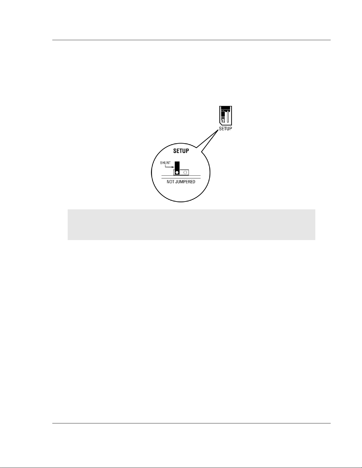
1.4 Setting Jumpers
The Setup Jumper acts as "write protection" for the module’s flash memory. In
"write protected" mode, the Setup pins are not connected, and the module’s
firmware cannot be overwritten. Do not jumper the Setup pins together unless
you are directed to do so by ProSoft Technical Support.
The following illustration shows the MVI56E-MNETC jumper configuration.
Note: If you are installing the module in a remote rack, you may prefer to leave
the Setup pins jumpered. That way, you can update the module’s firmware
without requiring physical access to the module.
ProSoft Technology, Inc. Page 15 of 183
February 3, 2013
Page 16

Guide to the MVI56E-MNETC User Manual MVI56E-MNETC ♦ ControlLogix Platform
User Manual Modbus TCP/IP Client Enhanced Communication Module
1.5 Installing the Module in the Rack
If you have not already installed and configured your ControlLogix processor and
power supply, please do so before installing the MVI56E-MNETC module. Refer
to your Rockwell Automation product documentation for installation instructions.
Warning: You must follow all safety instructions when installing this or any other
electronic devices. Failure to follow safety procedures could result in damage to
hardware or data, or even serious injury or death to personnel. Refer to the
documentation for each device you plan to connect to verify that suitable safety
procedures are in place before installing or servicing the device.
After you have checked the placement of the jumpers, insert the MVI56EMNETC into the ControlLogix chassis. Use the same technique recommended by
Rockwell Automation to remove and install ControlLogix modules.
You can install or remove ControlLogix system components while chassis power
is applied and the system is operating. However, please note the following
warning.
Warning: When you insert or remove the module while backplane power is on,
an electrical arc can occur. An electrical arc can cause personal injury or
property damage by sending an erroneous signal to your system’s actuators.
This can cause unintended machine motion or loss of process control. Electrical
arcs may also cause an explosion when they happen in a hazardous
environment. Verify that power is removed or the area is non-hazardous before
proceeding.
Repeated electrical arcing causes excessive wear to contacts on both the
module and its mating connector. Worn contacts may create electrical resistance
that can affect module operation.
1 Align the module with the top and bottom guides, and then slide it into the
rack until the module is firmly against the backplane connector.
2 With a firm, steady push, snap the module into place.
Page 16 of 183 ProSoft Technology, Inc.
February 3, 2013
Page 17

MVI56E-MNETC ♦ ControlLogix Platform Start Here
Modbus TCP/IP Client Enhanced Communication Module User Manual
3 Check that the holding clips on the top and bottom of the module are securely
in the locking holes of the rack.
4 Make a note of the slot location. You must identify the slot in which the
module is installed in order for the sample program to work correctly. Slot
numbers are identified on the green circuit board (backplane) of the
ControlLogix rack.
5 Turn power ON.
Note: If you insert the module improperly, the system may stop working or may
behave unpredictably.
ProSoft Technology, Inc. Page 17 of 183
February 3, 2013
Page 18

Guide to the MVI56E-MNETC User Manual MVI56E-MNETC ♦ ControlLogix Platform
File Name
Description
MVI56EMNETC_AddOn_Rung_v1_8.L5X
L5X file containing Add-On Instruction, user defined
data types, controller tags and ladder logic required
to configure the MVI56E-MNETC module
MVI56EMNETC_Optional_AddOn_Rung_v1_
0.L5X
Optional L5X file containing additional Add-On
Instruction with logic for changing Ethernet
configuration and clock settings.
User Manual Modbus TCP/IP Client Enhanced Communication Module
1.6 Importing the Sample Add-On Instruction
Note: This section only applies if your processor is using RSLogix 5000 version
16 or higher. If you have an earlier version, please see Using the Sample
Program (page 172).
Before You Begin
Two Add-On Instructions are provided for the MVI56E-MNETC module. The first
is required for setting up the module; the second is optional.
Copy the files from the ProSoft Solutions CD-ROM, or download them from
www.prosoft-technology.com. Save them to a convenient location in your PC,
such as Desktop or My Documents.
Page 18 of 183 ProSoft Technology, Inc.
February 3, 2013
Page 19
MVI56E-MNETC ♦ ControlLogix Platform Start Here
Modbus TCP/IP Client Enhanced Communication Module User Manual
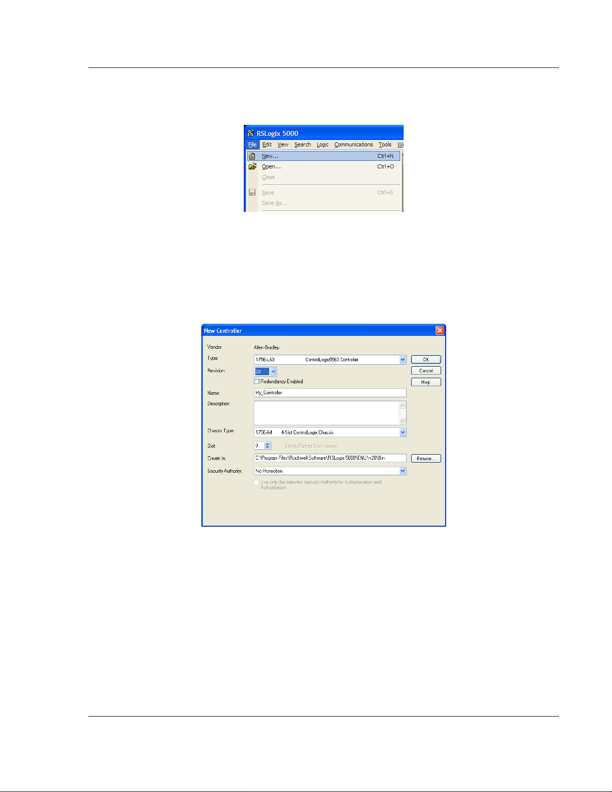
1.7 Creating a New RSLogix 5000 Project
1 Open the FILE menu, and then choose NEW.
2 Select your ControlLogix controller model.
3 Select REVISION 20. You can select an earlier revision number if you have an
earlier version of RSLogix. There may be some small differences in the
appearance of dialog boxes from the ones shown in this Guide.
4 Enter a name for your controller, such as My_Controller.
5 Select your ControlLogix chassis type.
6 Select SLOT 0 for the controller.
ProSoft Technology, Inc. Page 19 of 183
February 3, 2013
Page 20
Guide to the MVI56E-MNETC User Manual MVI56E-MNETC ♦ ControlLogix Platform
User Manual Modbus TCP/IP Client Enhanced Communication Module
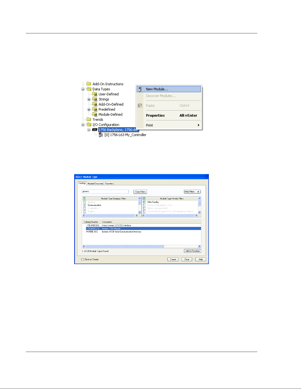
1.7.1 Creating the Module
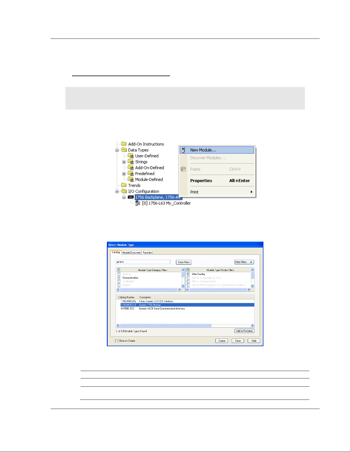
1 Add the MVI56E-MNETC module to the project.
In the Controller Organization window, select I/O CONFIGURATION and click
the right mouse button to open a shortcut menu. On the shortcut menu,
choose NEW MODULE.
This action opens the Select Module dialog box. Enter generic in the text box
and select the GENERIC 1756 MODULE. If you're using an earlier version of
RSLogix, expand OTHER in the Select Module dialog box, and then select the
GENERIC 1756 MODULE.
Page 20 of 183 ProSoft Technology, Inc.
February 3, 2013
Page 21
MVI56E-MNETC ♦ ControlLogix Platform Start Here
Modbus TCP/IP Client Enhanced Communication Module User Manual
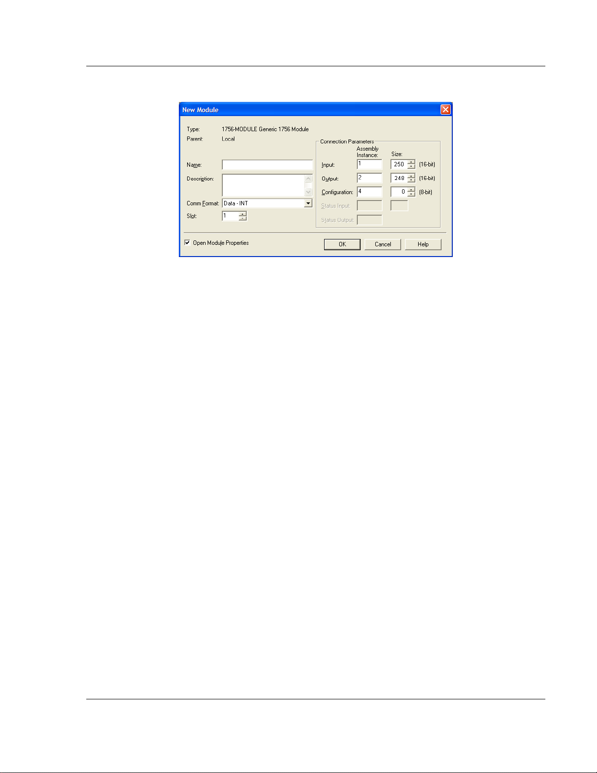
2 Click CREATE.This action opens the New Module dialog box.
ProSoft Technology, Inc. Page 21 of 183
February 3, 2013
Page 22
Guide to the MVI56E-MNETC User Manual MVI56E-MNETC ♦ ControlLogix Platform
Parameter
Value
Name
Enter a module identification string. Example: MNETC
Description
Enter a description for the module. Example: MODBUS TCP/IP
CLIENT ENHANCED COMMUNICATION MODULE
Comm Format
Select DATA-INT.
Slot
Enter the slot number in the rack where the MVI56E-MNETC
module is located.
Input Assembly Instance
1
Input Size
250
Output Assembly Instance
2
Output Size
248
Configuration Assembly Instance
4
Configuration Size
0
User Manual Modbus TCP/IP Client Enhanced Communication Module
3 In the New Module dialog box, enter the following values.
Important: You must select the Comm Format as DATA - INT in the dialog box;
otherwise the module will not communicate over the backplane of the
ControlLogix rack.
4 Click OK to continue.
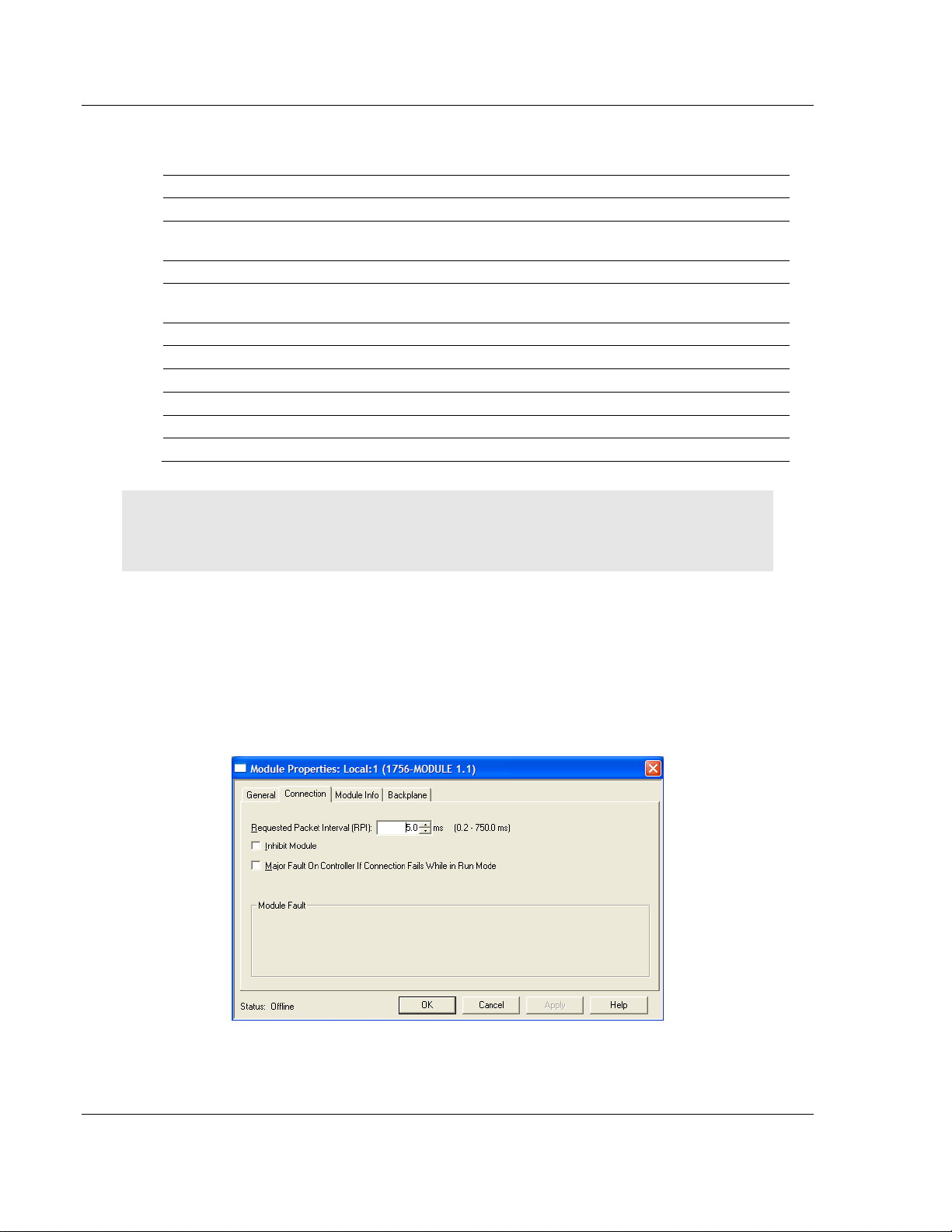
5 Edit the Module Properties. Select the Requested Packet Interval value for
scanning the I/O on the module. This value represents the minimum
frequency at which the module will handle scheduled events. This value
should not be set to less than 1 millisecond. The default value is 5
milliseconds. Values between 1 and 10 milliseconds should work with most
applications.
6 Save the module.
Page 22 of 183 ProSoft Technology, Inc.
February 3, 2013
Page 23
MVI56E-MNETC ♦ ControlLogix Platform Start Here
Modbus TCP/IP Client Enhanced Communication Module User Manual
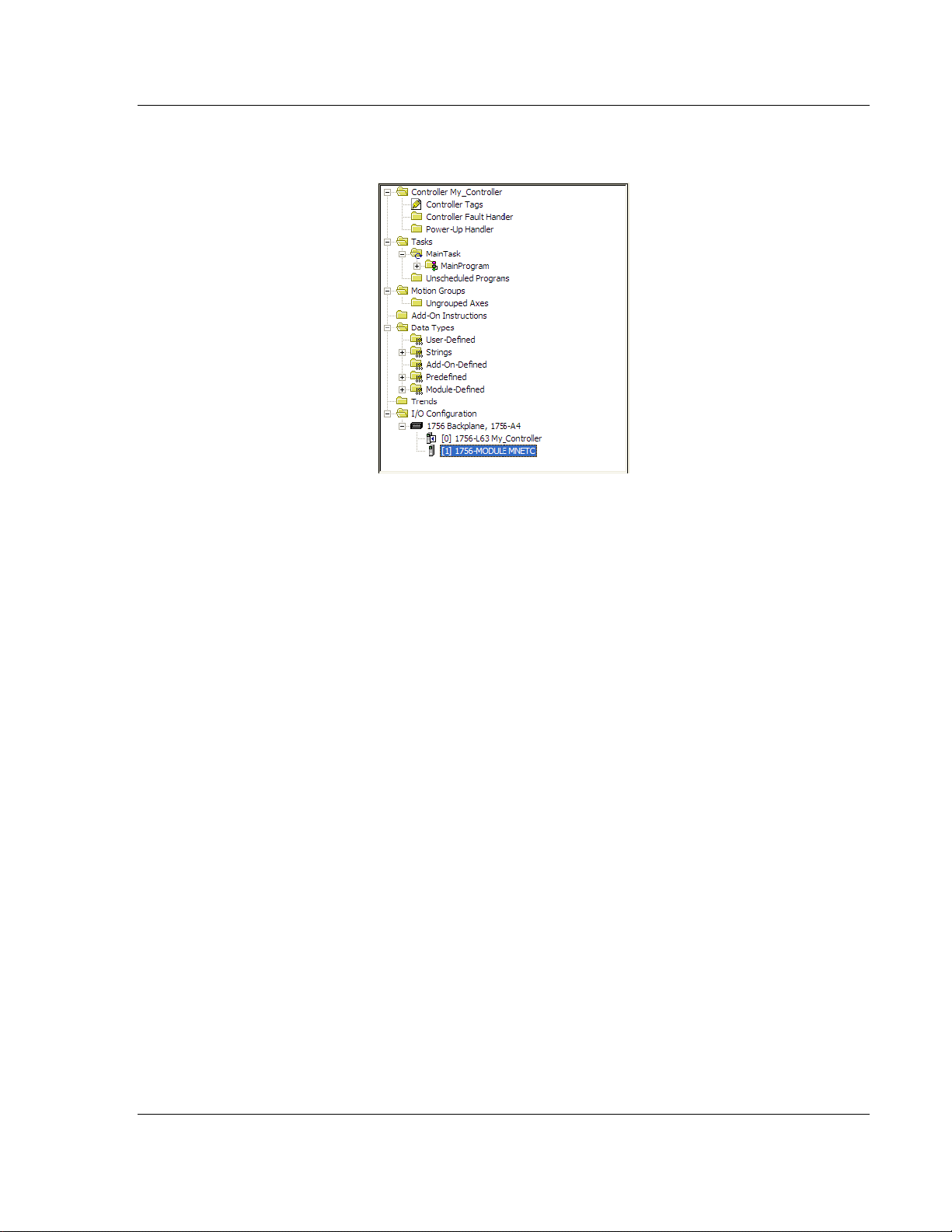
Click OK to close the dialog box. Notice that the module now appears in the
Controller Organization window.
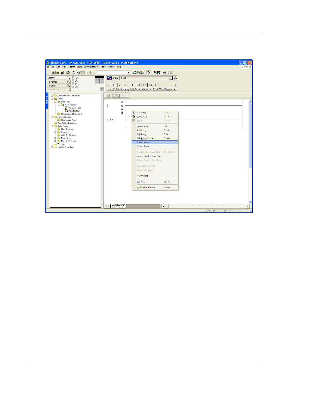
1.7.2 Importing the Add-On Instruction
1 In the Controller Organization window, expand the TASKS folder and
subfolder until you reach the MAINPROGRAM folder.
2 In the MAINPROGRAM folder, double-click to open the MAINROUTINE ladder.
ProSoft Technology, Inc. Page 23 of 183
February 3, 2013
Page 24
Guide to the MVI56E-MNETC User Manual MVI56E-MNETC ♦ ControlLogix Platform
User Manual Modbus TCP/IP Client Enhanced Communication Module
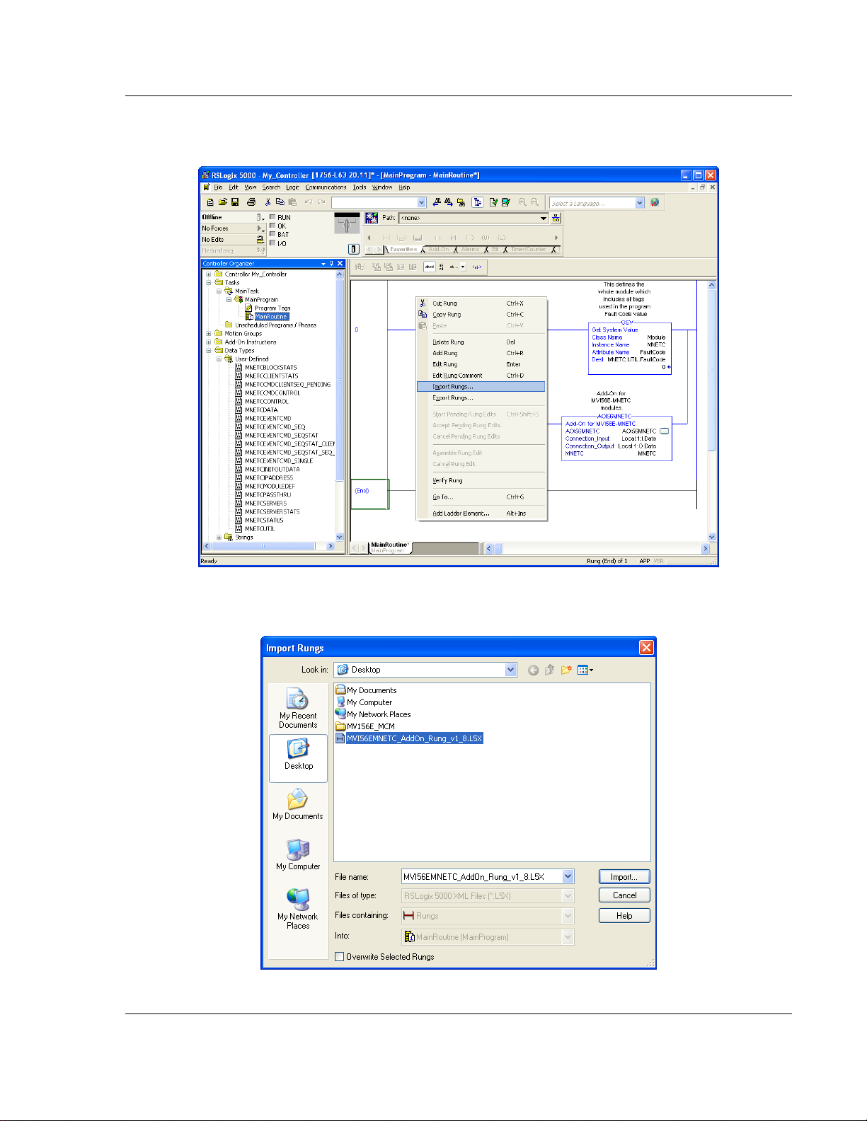
3 Select an empty rung in the new routine, and then click the right mouse
button to open a shortcut menu. On the shortcut menu, choose IMPORT RUNG.
Page 24 of 183 ProSoft Technology, Inc.
February 3, 2013
Page 25
MVI56E-MNETC ♦ ControlLogix Platform Start Here
Modbus TCP/IP Client Enhanced Communication Module User Manual
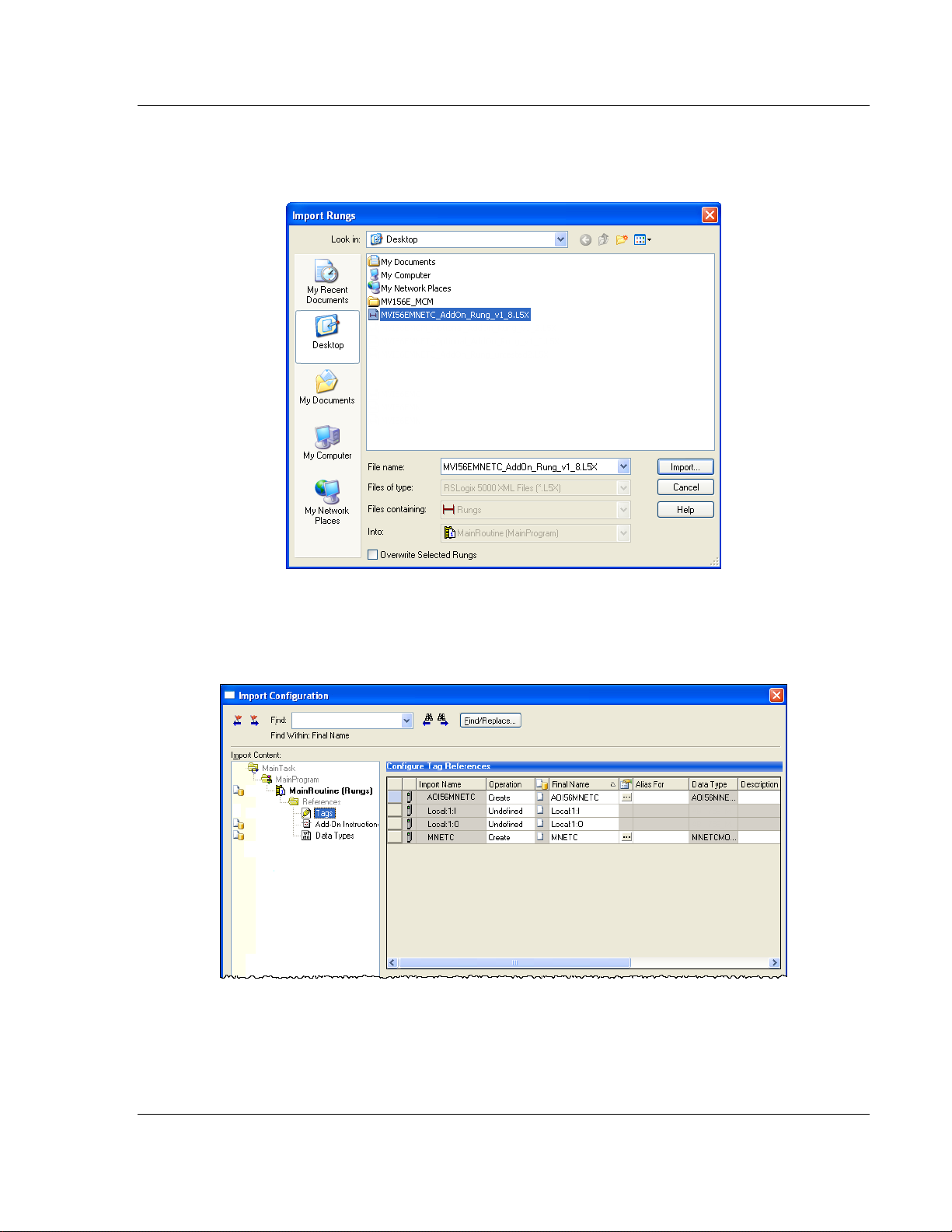
4 Navigate to the location on your PC where you saved (page 18) the Add-On
Instruction (for example, My Documents or Desktop). Select the
MVI56EMNETC_ADDON_RUNG_V1_8.L5X file.
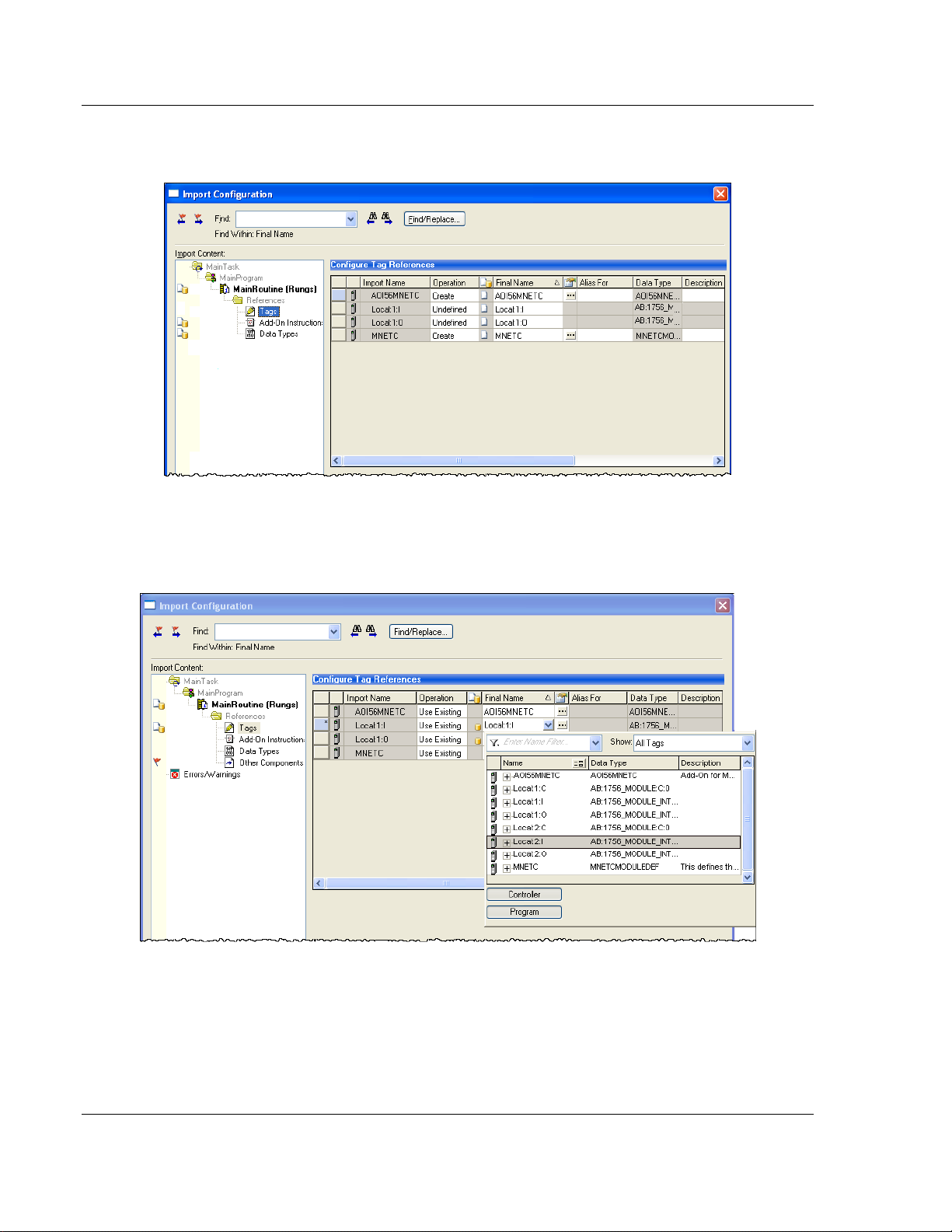
This action opens the Import Configuration dialog box. Click TAGS under
MAINROUTINE to show the controller tags that will be created. Note that if you
are using a controller revision number of 16 or less, the Import Configuration
dialog box does not show the IMPORT CONTENT tree.
ProSoft Technology, Inc. Page 25 of 183
February 3, 2013
Page 26
Guide to the MVI56E-MNETC User Manual MVI56E-MNETC ♦ ControlLogix Platform
User Manual Modbus TCP/IP Client Enhanced Communication Module
5 If you are using the module in a different slot (or remote rack), edit the
connection input and output variables that define the path to the module in
the FINAL NAME column (NAME column for controller revision 16 or less). For
example, if your module is located in slot 3, change Local:1:I in the above
picture to Local:3:I. Do the same for Local:1:O. If your module is located in
Slot 1 of the local rack, this step is not required.
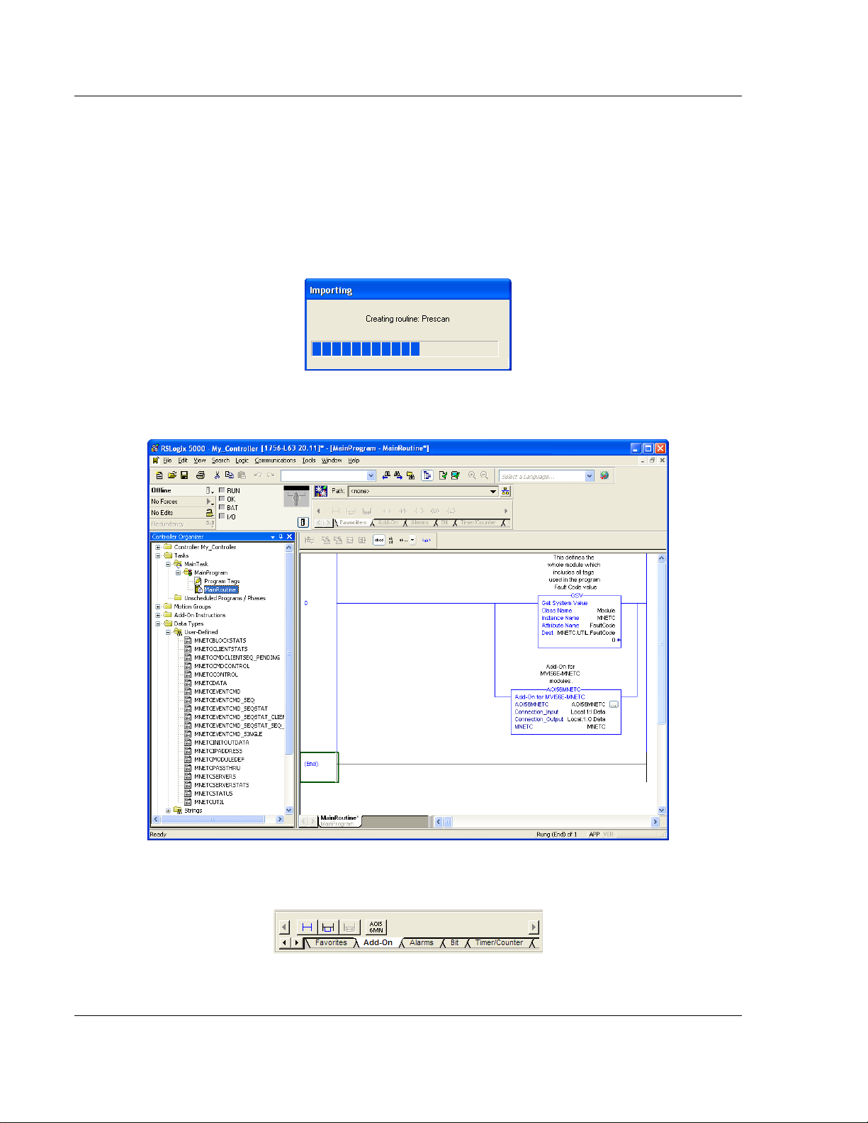
6 Click OK to confirm the import. RSLogix will indicate that the import is in
progress:
When the import is completed, the new rung with the Add-On Instruction will
be visible as shown in the following illustration.
The procedure has also imported new user-defined data types, data objects
and the Add-On Instruction for your project.
Page 26 of 183 ProSoft Technology, Inc.
February 3, 2013
Page 27
MVI56E-MNETC ♦ ControlLogix Platform Start Here
Parameter
Value
Name
Enter a module identification string. Example: MNETC_2.
Description
Enter a description for the module. Example: MODBUS TCP/IP
CLIENT ENHANCED COMMUNICATION MODULE
Modbus TCP/IP Client Enhanced Communication Module User Manual
7 Save the application and then download the sample ladder logic to the
processor.
Adding Multiple Modules (Optional)
Important: If your application requires more than one MVI56-MNETC module in
the same project, follow the steps below.
1 In the I/O CONFIGURATION folder, click the right mouse button to open a
shortcut menu, and then choose NEW MODULE.
2 Select 1756-MODULE. If you’re using a controller revision of 16 or less,
expand OTHER in the Select Module dialog box, and then select the 1756-
MODULE.
3 Fill the module properties as follows:
ProSoft Technology, Inc. Page 27 of 183
February 3, 2013
Page 28
Guide to the MVI56E-MNETC User Manual MVI56E-MNETC ♦ ControlLogix Platform
Parameter
Value
Comm Format
Select DATA-INT.
Slot
Enter the slot number in the rack where the MVI56E-MNETC
module is located.
Input Assembly Instance
1
Input Size
250
Output Assembly Instance
2
Output Size
248
Configuration Assembly Instance
4
Configuration Size
0
User Manual Modbus TCP/IP Client Enhanced Communication Module
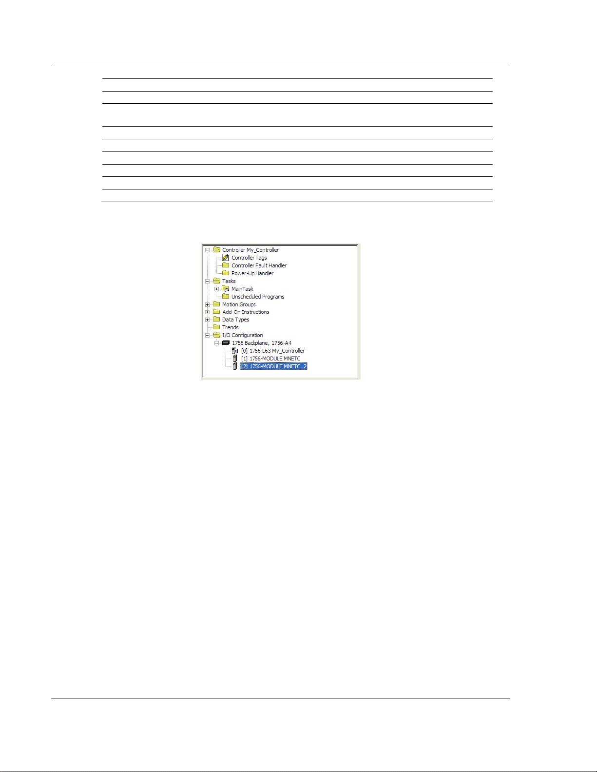
4 Click OK to confirm. The new module is now visible:
5 Expand the TASKS folder, and then expand the MAINTASK folder.
6 In the MAINPROGRAM folder, double-click to open the MAINROUTINE ladder.
Page 28 of 183 ProSoft Technology, Inc.
February 3, 2013
Page 29
MVI56E-MNETC ♦ ControlLogix Platform Start Here
Modbus TCP/IP Client Enhanced Communication Module User Manual
7 Select an empty rung in the routine, and then click the right mouse button to
open a shortcut menu. On the shortcut menu, choose IMPORT RUNGS.
8 Select the MVI56EMNETC_ADDON_RUNG_V1_8.L5X file, and then click
IMPORT.
ProSoft Technology, Inc. Page 29 of 183
February 3, 2013
Page 30
Guide to the MVI56E-MNETC User Manual MVI56E-MNETC ♦ ControlLogix Platform
User Manual Modbus TCP/IP Client Enhanced Communication Module
9 This action opens the Import Configuration window Click TAGS under
MAINROUTINE to show the controller tags that will be created.
10 Associate the I/O connection variables to the correct module. The default
values are Local:1:I and Local:1:O so you may have to edit the Final Name
field to change the values. You can also click the drop-down arrow to select
the correct name.
11 Change the default tags MNETC and AOI56MNETC to avoid conflict with
existing tags. In this step, you should append a string to the default tag
names, such as "_2", as shown in the following illustration.
Page 30 of 183 ProSoft Technology, Inc.
February 3, 2013
Page 31

MVI56E-MNETC ♦ ControlLogix Platform Start Here
Modbus TCP/IP Client Enhanced Communication Module User Manual
12 Click OK to confirm.
The setup procedure is now complete. Save the project and download the
application to your ControlLogix processor.
ProSoft Technology, Inc. Page 31 of 183
February 3, 2013
Page 32

Guide to the MVI56E-MNETC User Manual MVI56E-MNETC ♦ ControlLogix Platform
User Manual Modbus TCP/IP Client Enhanced Communication Module
Adjusting the Input and Output Array Sizes
Tip: If you have not installed ProSoft Configuration Builder, see page 38 for the
steps to install the software.
The module internal database is divided into two user-configurable areas:
Read Data
Write Data
The Read Data area is moved from the module to the processor, while the Write
Data area is moved from the processor to the module.
The MVI56E-MNETC Add-On Instruction rung is configured for 600 registers of
Read Data and 600 registers of Write Data, which is sufficient for most
applications. However, you can configure the sizes of these data areas to meet
the needs of your application.
1 In ProSoft Configuration Builder, expand the Module icon in the tree view and
double-click MODULE to open an Edit window. Change the READ REGISTER
COUNT to contain the number of words for your Read Data area.
Important: Because the module pages data in blocks of 200 registers at a time,
you should configure your user data areas in multiples of 200 registers.
2 To modify the WriteData array, follow the above steps, substituting WriteData
for ReadData.
Page 32 of 183 ProSoft Technology, Inc.
February 3, 2013
Page 33

MVI56E-MNETC ♦ ControlLogix Platform Start Here
Modbus TCP/IP Client Enhanced Communication Module User Manual
3 Save and download the configuration to the module (page 65) and reboot.
Make sure that the ReadData and WriteData arrays do not overlap in the module
memory. For example, if your application requires 2000 words of WriteData
starting at register 0, then your Read Register Start parameter must be set to a
value of 2000 or greater.
ProSoft Technology, Inc. Page 33 of 183
February 3, 2013
Page 34

Guide to the MVI56E-MNETC User Manual MVI56E-MNETC ♦ ControlLogix Platform
User Manual Modbus TCP/IP Client Enhanced Communication Module
1.8 Connecting Your PC to the ControlLogix Processor
There are several ways to establish communication between your PC and the
ControlLogix processor. The following steps show how to establish
communication through the serial interface. It is not mandatory that you use the
processor's serial interface. You may access the processor through whatever
network interface is available on your system. Refer to your Rockwell Automation
documentation for information on other connection methods.
1 Connect the right-angle connector end of the cable to your controller at the
communications port.
2 Connect the straight connector end of the cable to the serial port on your
computer.
Page 34 of 183 ProSoft Technology, Inc.
February 3, 2013
Page 35

MVI56E-MNETC ♦ ControlLogix Platform Start Here
Modbus TCP/IP Client Enhanced Communication Module User Manual
1.9 Downloading the Sample Program to the Processor
Note: The key switch on the front of the ControlLogix processor must be in the
REM or PROG position.
1 If you are not already online with the processor, open the Communications
menu, and then choose DOWNLOAD. RSLogix 5000 will establish
communication with the processor. You do not have to download through the
processor's serial port, as shown here. You may download through any
available network connection.
2 When communication is established, RSLogix 5000 will open a confirmation
dialog box. Click the DOWNLOAD button to transfer the sample program to the
processor.
3 RSLogix 5000 will compile the program and transfer it to the processor. This
process may take a few minutes.
4 When the download is complete, RSLogix 5000 will open another
confirmation dialog box. If the key switch is in the REM position, click OK to
switch the processor from PROGRAM mode to RUN mode.
Note: If you receive an error message during these steps, refer to your RSLogix
documentation to interpret and correct the error.
ProSoft Technology, Inc. Page 35 of 183
February 3, 2013
Page 36

Guide to the MVI56E-MNETC User Manual MVI56E-MNETC ♦ ControlLogix Platform
User Manual Modbus TCP/IP Client Enhanced Communication Module
Page 36 of 183 ProSoft Technology, Inc.
February 3, 2013
Page 37

MVI56E-MNETC ♦ ControlLogix Platform Configuring the MVI56E-MNETC Module
In This Chapter
Installing ProSoft Configuration Builder ................................................. 38
Using ProSoft Configuration Builder Software ....................................... 39
Connecting Your PC to the Module ....................................................... 61
Downloading the Project to the Module ................................................. 65
Modbus TCP/IP Client Enhanced Communication Module User Manual
2 Configuring the MVI56E-MNETC Module
ProSoft Technology, Inc. Page 37 of 183
February 3, 2013
Page 38

Guide to the MVI56E-MNETC User Manual MVI56E-MNETC ♦ ControlLogix Platform
User Manual Modbus TCP/IP Client Enhanced Communication Module
2.1 Installing ProSoft Configuration Builder
To install ProSoft Configuration Builder from the CD-ROM
1 Insert the ProSoft Solutions CD-ROM into the CD drive of your PC. Wait for
the startup screen to appear.
2 On the startup screen, click INSTALL PROSOFT CONFIGURATION BUILDER. This
action starts the installation wizard for ProSoft Configuration Builder.
3 Click NEXT on each page of the installation wizard. Click FINISH on the last
page of the wizard.
Page 38 of 183 ProSoft Technology, Inc.
February 3, 2013
Page 39

MVI56E-MNETC ♦ ControlLogix Platform Configuring the MVI56E-MNETC Module
Modbus TCP/IP Client Enhanced Communication Module User Manual
2.2 Using ProSoft Configuration Builder Software
ProSoft Configuration Builder (PCB) provides a convenient way to manage
module configuration files customized to meet your application needs. PCB is not
only a powerful solution for new configuration files, but also allows you to import
information from previously installed (known working) configurations to new
projects.
Note: During startup and initialization, the MVI56E-MNETC module receives its
protocol and backplane configuration information from the installed Personality
Module (Compact Flash). Use ProSoft Configuration Builder to configure module
settings and to download changes to the Personality Module.
2.2.1 Upgrading from MVI56-MNETC in ProSoft Configuration
Builder
MVI56E-MNETC modules are fully backward-compatible with MVI56-MNETC
modules. However, you will need to convert your MVI56-MNETC configuration in
ProSoft Configuration Builder to a form that your new MVI56E-MNETC module
will accept when you download it.
ProSoft Configuration Builder version 2.2.2 or later has an upgrade option that
easily performs this conversion, while preserving all your configuration settings
and any name you may have given your module.
Important: For this procedure, you need to have ProSoft Configuration Builder
version 2.2.2 or later installed on your PC. You can download the latest version
from www.prosoft-technology.com.
1 In ProSoft Configuration Builder's tree view, click the MODULE icon and right-
click to open a shortcut menu.
2 On the shortcut menu, select CHANGE MODULE TYPE TO MVI56E-MNETC.
ProSoft Technology, Inc. Page 39 of 183
February 3, 2013
Page 40

Guide to the MVI56E-MNETC User Manual MVI56E-MNETC ♦ ControlLogix Platform
User Manual Modbus TCP/IP Client Enhanced Communication Module
2.2.2 Setting Up the Project
To begin, start PROSOFT CONFIGURATION BUILDER (PCB).
If you have used other Windows configuration tools before, you will find the
screen layout familiar. PCB’s window consists of a tree view on the left, and an
information pane and a configuration pane on the right side of the window. When
you first start PCB, the tree view consists of folders for Default Project and
Default Location, with a Default Module in the Default Location folder. The
following illustration shows the PCB window with a new project.
Your first task is to add the MVI56E-MNETC module to the project.
1 Use the mouse to select DEFAULT MODULE in the tree view, and then click the
right mouse button to open a shortcut menu.
Page 40 of 183 ProSoft Technology, Inc.
February 3, 2013
Page 41

MVI56E-MNETC ♦ ControlLogix Platform Configuring the MVI56E-MNETC Module
Modbus TCP/IP Client Enhanced Communication Module User Manual
2 On the shortcut menu, select CHOOSE MODULE TYPE. This action opens the
Choose Module Type dialog box.
3 In the Product Line Filter area of the dialog box, select MVI56E. In the Select
Module Type dropdown list, select MVI56E-MNETC, and then click OK to
save your settings and return to the ProSoft Configuration Builder window.
ProSoft Technology, Inc. Page 41 of 183
February 3, 2013
Page 42

Guide to the MVI56E-MNETC User Manual MVI56E-MNETC ♦ ControlLogix Platform
User Manual Modbus TCP/IP Client Enhanced Communication Module
2.2.3 Setting Module Parameters
Notice that the contents of the information pane and the configuration pane
changed when you added the MVI56E-MNETC module to the project.
At this time, you may wish to rename the Default Project and Default Location
folders in the tree view.
Renaming an Object
1 Select the object, and then click the right mouse button to open a shortcut
menu. From the shortcut menu, choose RENAME.
2 Type the name to assign to the object.
3 Click away from the object to save the new name.
Configuring Module Parameters
1 Click the [+] sign next to the module icon to expand module information.
2 Click the [+] sign next to any icon to view module information and
configuration options.
3 Double-click any icon to open an Edit dialog box.
4 To edit a parameter, select the parameter in the left pane and make your
changes in the right pane.
5 Click OK to save your changes.
Page 42 of 183 ProSoft Technology, Inc.
February 3, 2013
Page 43

MVI56E-MNETC ♦ ControlLogix Platform Configuring the MVI56E-MNETC Module
Modbus TCP/IP Client Enhanced Communication Module User Manual
Printing a Configuration File
1 Select the module icon, and then click the right mouse button to open a
shortcut menu.
2 On the shortcut menu, choose VIEW CONFIGURATION. This action opens the
View Configuration window.
3 In the View Configuration window, open the FILE menu, and choose PRINT.
This action opens the Print dialog box.
4 In the Print dialog box, choose the printer to use from the drop-down list,
select printing options, and then click OK.
2.2.4 Module
This section of the configuration describes the database setup and module-level
parameters.
Backplane Error/Status Pointer
1 to 9955
This parameter sets the address in the internal database where the backplane
error/status data will be placed. If you want the error/status data to be moved to
the processor and placed into the ReadData array, the value entered should be a
module memory address in the Read Data area. If the value is set to -1, the
error/status data will not be stored in the module's internal database and will not
be transferred to the processor's ReadData array.
Enabling the Error/Status Pointer is optional. The error/status data is routinely
returned as part of the input image, which is continually being transferred from
the module to the processor. For more information, see Normal Data Transfer
Blocks (page 114).
Read Register Start
0 to 9999
The Read Register Start parameter specifies the start of the Read Data area in
module memory. Data in this area will be transferred from the module to the
processor.
Note: Total user database memory space is limited to the first 10,000 registers of
module memory, addresses 0 through 9999. Therefore, the practical limit for this
parameter is 9999 minus the value entered for Read Register Count, so that the
Read Data Area does not try to extend above address 9999. Read Data and
Write Data Areas must be configured to occupy separate address ranges in
module memory and should not be allowed to overlap.
Note: To use the extended database registers, your MVI56E-MNETC module needs to have
firmware version 3.01 or higher, and your MVI56E-MNETC Add-On Instruction needs to be version
1.8 or higher. Earlier versions support up to 5000 database registers.
ProSoft Technology, Inc. Page 43 of 183
February 3, 2013
Page 44

Guide to the MVI56E-MNETC User Manual MVI56E-MNETC ♦ ControlLogix Platform
User Manual Modbus TCP/IP Client Enhanced Communication Module
Read Register Count
0 to 10,000
The Read Register Count parameter specifies the size of the Read Data area of
module memory and the number of registers to transfer from this area to the
processor, up to a maximum of 10,000 words.
Note: Total Read Register Count and Write Register Count cannot exceed
10,000 total registers. Read Data and Write Data Areas must be configured to
occupy separate address ranges in module memory and should not be allowed
to overlap.
Write Register Start
0 to 9999
The Write Register Start parameter specifies the start of the Write Data area in
module memory. Data in this area will be transferred in from the processor.
Note: Total user database memory space is limited to the first 10,000 registers of
module memory, addresses 0 through 9999. Therefore, the practical limit for this
parameter is 9999 minus the value entered for Write Register Count, so that the
Write Data Area does not try to extend above address 9999. Read Data and
Write Data Areas must be configured to occupy separate address ranges in
module memory and should not be allowed to overlap.
Write Register Count
0 to 10,000
The Write Register Count parameter specifies the size of the Write Data area of
module memory and the number of registers to transfer from the processor to
this memory area, up to a maximum value of 5000 words.
Note: Total Read Register Count and Write Register Count cannot exceed
10,000 total registers. Read Data and Write Data Areas must be configured to
occupy separate address ranges in module memory and should not be allowed
to overlap.
Page 44 of 183 ProSoft Technology, Inc.
February 3, 2013
Page 45

MVI56E-MNETC ♦ ControlLogix Platform Configuring the MVI56E-MNETC Module
Modbus TCP/IP Client Enhanced Communication Module User Manual
Failure Flag Count
If this value is greater than zero the protocol communication will be interrupted
once a backplane failure is detected, or communication with the processor fails.
A value of zero will disable this feature.
Initialize Output Data
0 = No, 1 = Yes
This parameter is used to determine if th e output data for the module should be i nitialized with values from the processor. I f the value is set to 0, the output data will be initialized to 0. If the value is s et to 1, the data will be initialized with d ata from the processor. Use of this opti on requires associated ladder logic to pass t he data from the processor to the mo dule.
Pass-Through Mode
0, 1, 2 or 3
This parameter specifies the pass-through mode for write messages received by
the MNET and MBAP server ports.
If the parameter is set to 0, all write messages will be placed in the module’s
virtual database.
If a value of 1 is entered, write messages received will be sent to the
processor as unformatted messages.
If a value of 2 is entered, write messages received will be sent to the
processor as formatted messages.
If a value of 3 is entered, write messages received will be sent to the
processor with the bytes swapped in a formatted message.
Note: To use pass-through mode, your MVI56E-MNETC module needs to have firmware version
3.01 or higher, and your MVI56E-MNETC Add-On Instruction needs to be version 1.8 or higher.
Earlier versions do not support pass-through mode.
Duplex/Speed Code
0, 1, 2, 3 or 4
This parameter allows you to cause the module to use a specific duplex and
speed setting.
Value = 1: Half duplex, 10 MB speed
Value = 2: Full duplex, 10 MB speed
Value = 3: Half duplex, 100 MB speed
Value = 4: Full duplex, 100 MB speed
Value = 0: Auto-negotiate
Auto-negotiate is the default value for backward compatibility. This feature is not
implemented in older software revisions.
ProSoft Technology, Inc. Page 45 of 183
February 3, 2013
Page 46

Guide to the MVI56E-MNETC User Manual MVI56E-MNETC ♦ ControlLogix Platform
User Manual Modbus TCP/IP Client Enhanced Communication Module
2.2.5 MNET Servers
This section contains database offset information used by the server when
accessed by external Clients. These offsets can be utilized to segment the
database by data type.
Note: To use the server capabilities, your MVI56E-MNETC module needs to have firmware version
3.01 or higher, and your MVI56E-MNETC Add-On Instruction needs to be version 1.8 or higher.
Earlier versions do not support server capabilities.
Float Flag
YES or NO
This flag specifies how the server driver will respond to Function Code 3, 6, and
16 commands (read and write Holding Registers) from a remote Client when it is
moving 32-bit floating-point data.
If the remote Client expects to receive or will send one complete 32-bit floatingpoint value for each count of one (1), then set this parameter to YES. When set to
YES, the server driver will return values from two consecutive 16-bit internal
memory registers (32 total bits) for each count in the read command, or receive
32-bits per count from the Client for write commands. Example: Count = 10,
server driver will send 20 16-bit registers for 10 total 32-bit floating-point values.
Page 46 of 183 ProSoft Technology, Inc.
February 3, 2013
Page 47

MVI56E-MNETC ♦ ControlLogix Platform Configuring the MVI56E-MNETC Module
Modbus TCP/IP Client Enhanced Communication Module User Manual
If, however, the remote Client sends a count of two (2) for each 32-bit floatingpoint value it expects to receive or send, or, if you do not plan to use floatingpoint data in your application, then set this parameter to NO, which is the default
setting.
You will also need to set the Float Start and Float Offset parameters to
appropriate values whenever the Float Flag parameter is set to YES.
Float Start
0 TO 65535
Whenever the Float Flag parameter is set to YES, this parameter determines the
lowest Modbus Address, received in commands from a remote Client, to consider
as requests to read or write floating-point data. All commands with address
values greater than or equal to this value will be considered floating-point data
requests. All commands with address values less than this value will be
considered normal 16-bit register data requests.
This parameter is used only if the Float Flag is set to YES. For example, if a value
of 7000 is entered, all commands received with addresses of 47001 (or 407001)
and above will be considered as requests for floating-point data and 32-bits of
data will be returned for each count of one in the command.
You will also need to set the Float Offset parameter to an appropriate value
whenever the Float Flag parameter is set to YES.
Float Offset
0 to 9999
This parameter defines the start register for floating-point data in the internal
database. This parameter is used only if the Float Flag is enabled. For example,
if the Float Offset value is set to 3000 and the Float Start parameter is set to
7000, data requests for register 7000 will use the internal Modbus register 3000.
Output Offset
0 to 9999
This parameter defines the start register for the Modbus command data in the
internal database. This parameter is enabled when a value greater than 0 is set.
For example, if the Output Offset value is set to 3000, data requests for Modbus
Coil Register address 00001 will use the internal database register 3000, bit 0. If
the Output Offset value is set to 3000, data requests for Modbus Coil register
address 00016 will use the internal database register 3000, bit 15. Function
codes affected are 1, 5, and 15.
ProSoft Technology, Inc. Page 47 of 183
February 3, 2013
Page 48

Guide to the MVI56E-MNETC User Manual MVI56E-MNETC ♦ ControlLogix Platform
User Manual Modbus TCP/IP Client Enhanced Communication Module
Bit Input Offset
0 to 9999
This parameter defines the start register for Modbus command data in the
internal database. This parameter is enabled when a value greater than 0 is set.
For example, if the Bit Input Offset value is set to 3000, data requests for Modbus
Input Register address 10001 will use the internal database register 3000, bit 0. If
the Bit Input Offset is set to 3000, data requests for Modbus Coil register address
10016 will use the internal database register 3000, bit 15. Function code 2 is
affected.
Holding Register Offset
0 to 9999
This parameter defines the start register for the Modbus Command data in the
internal database. This parameter is enabled when a value greater than 0 is set.
For example, if the Holding Register Offset value is set to 4000, data requests for
Modbus Word register 40001 will use the internal database register 4000.
Function codes affected are 3, 6, 16, & 23.
Word Input Offset
0 to 9999
This parameter defines the start register for Modbus Command data in the
internal database. This parameter is enabled when a value greater than 0 is set.
For example, if the Word Input Offset value is set to 4000, data requests for
Modbus Word register address 30001 will use the internal database register
4000. Function code 4 is affected.
Connection Timeout
0 to 1200 seconds
This is the number of seconds the server will wait to receive new data. If the
server does not receive any new data during this time, it will close the
connection.
2.2.6 MNET Client x
This section defines general configuration for the MNET Client (Master).
Page 48 of 183 ProSoft Technology, Inc.
February 3, 2013
Page 49

MVI56E-MNETC ♦ ControlLogix Platform Configuring the MVI56E-MNETC Module
Modbus TCP/IP Client Enhanced Communication Module User Manual
Client Error/Status Pointer
-1 to 9990
This parameter sets the address in the internal database where the Client
error/status data will be placed. If you want the error/status data to be moved to
the processor and placed into the ReadData array, the value entered should be a
module memory address in the Read Data area. If the value is set to -1, the
error/status data will not be stored in the module's internal database and will not
be transferred to the processor's ReadData array.
Enabling the Error/Status Pointer is optional. Alternatively, the error/status data
for a specific Client can be requested by the processor and returned in a special
Client Status block. For more information, see Client Status Blocks (page 122).
Command Error Pointer
-1 to 9984
This parameter sets the address in the internal database where the Command
Error List data will be placed. If you want the Command Error List data to be
moved to the processor and placed into the ReadData array, the value entered
should be a module memory address in the Read Data area. If the value is set to
-1, the Command Error List data will not be stored in the module's internal
database and will not be transferred to the processor's ReadData array.
Enabling the Command Error Pointer is optional. Alternatively, the Command
Error List data for a specific Client can be requested by the processor and
returned in a special Client Status block. For more information, see Client Status
Blocks (page 122).
Minimum Command Delay
0 to 65535 milliseconds
This parameter specifies the number of milliseconds to wait between the initial
issuances of a command. This parameter can be used to delay all commands
sent to servers to avoid "flooding" commands on the network. This parameter
does not affect retries of a command as they will be issued when failure is
recognized.
Response Timeout
0 to 65535 milliseconds
This is the time in milliseconds that a Client will wait before re-transmitting a
command if no response is received from the addressed server. The value to use
depends on the type of communication network used, and the expected
response time of the slowest device on the network.
Retry Count
0 to 10
This parameter specifies the number of times a command will be retried if it fails.
ProSoft Technology, Inc. Page 49 of 183
February 3, 2013
Page 50

Guide to the MVI56E-MNETC User Manual MVI56E-MNETC ♦ ControlLogix Platform
User Manual Modbus TCP/IP Client Enhanced Communication Module
Float Flag
YES or NO
This flag specifies how the Client driver will issue Function Code 3, 6, and 16
commands (read and write Holding Registers) to a remote server when it is
moving 32-bit floating-point data.
If the remote server expects to receive or will send one complete 32-bit floatingpoint value for each count of one (1), then set this parameter to YES. When set to
YES, the Client driver will send values from two consecutive 16-bit internal
memory registers (32 total bits) for each count in a write command, or receive 32
bits per count from the server for read commands. Example: Count = 10, Client
driver will send 20 16-bit registers for 10 total 32-bit floating-point values.
If, however, the remote server expects to use a count of two (2) for each 32-bit
floating-point value it sends or receives, or if you do not plan to use floating-point
data in your application, then set this parameter to NO, which is the default
setting.
You will also need to set the Float Start and Float Offset parameters to
appropriate values whenever the Float Flag parameter is set to YES.
Float Start
0 to 65535
Whenever the Float Flag parameter is set to YES, this parameter determines the
lowest Modbus Address, used in commands to a remote server, to consider as
commands to read or write floating-point data. All commands with address values
greater than or equal to this value will be considered floating-point data
commands. All commands with address values less than this value will be
considered normal 16-bit register data commands.
This parameter is used only if the Float Flag is set to YES. For example, if a value
of 7000 is entered, all commands sent with addresses of 47001 (or 407001) and
above will be considered as floating-point data commands and 32 bits of data will
be sent or received for each count of one in the command.
You will also need to set the Float Offset parameter to an appropriate value
whenever the Float Flag parameter is set to YES.
Float Offset
0 to 9999
This parameter defines the start register for floating-point data in the internal
database. This parameter is used only if the Float Flag is enabled. For example,
if the Float Offset value is set to 3000 and the Float Start parameter is set to
7000, data requests for register 7000 will use the internal Modbus register 3000.
ARP Timeout
1 to 60
This parameter specifies the number of seconds to wait for an ARP reply after a
request is issued.
Page 50 of 183 ProSoft Technology, Inc.
February 3, 2013
Page 51

MVI56E-MNETC ♦ ControlLogix Platform Configuring the MVI56E-MNETC Module
Modbus TCP/IP Client Enhanced Communication Module User Manual
Command Error Delay
0 to 300
This parameter specifies the number of 100 millisecond intervals to turn off a
command in the error list after an error is recognized for the command. If this
parameter is set to 0, there will be no delay.
MBAP Port Override
YES or NO
If this parameter is set to YES, all messages generated by the Client driver will be
MBAP format messages to all Service Port values.
If this parameter is set to NO (default value), or is omitted from the configuration
file, all messages sent to Service Port 502 will be MBAP format messages, and
all other Service Ports values will use the encapsulated Modbus message format
(MNET).
Each Client is configured independently in the configuration file.
This parameter applies to firmware version 1.05 and above. For downward
compatibility, you may omit this parameter from the Client's configuration.
2.2.7 MNET Client x Commands
The MNET Client x Commands section of the configuration sets the Modbus
TCP/IP Client command list. This command list polls Modbus TCP/IP server
devices attached to the Modbus TCP/IP Client port. The module supports
numerous commands. This permits the module to interface with a wide variety of
Modbus TCP/IP protocol devices.
The function codes used for each command are those specified in the Modbus
protocol. Each command list record has the same format. The first part of the
record contains the information relating to the MVI56E-MNETC communication
module, and the second part contains information required to interface to the
Modbus TCP/IP server device.
ProSoft Technology, Inc. Page 51 of 183
February 3, 2013
Page 52

Guide to the MVI56E-MNETC User Manual MVI56E-MNETC ♦ ControlLogix Platform
Function Code
Definition
Supported in Client
Supported in Server
1
Read Coil Status
X X 2
Read Input Status
X
X
3
Read Holding Registers
X
X
4
Read Input Registers
X X 5
Force (Write) Single Coil
X X 6
Preset (Write) Single Register
X X 7
Read Exception Status
X X 8
Diagnostics
X 15
Force (Write) Multiple Coils
X
X
16
Preset (Write) Multiple
Registers
X
X
22
Mask Write 4X
X 23
Read/Write
X
User Manual Modbus TCP/IP Client Enhanced Communication Module
Command List Overview
In order to interface the module with Modbus TCP/IP server devices, you must
construct a command list. The commands in the list specify the server device to
be addressed, the function to be performed (read or write), the data area in the
device to interface with, and the registers in the internal database to be
associated with the device data. The Client command list supports up to 16
commands.
The command list is processed from top (command #1) to bottom. A poll interval
parameter is associated with each command to specify a minimum delay time in
tenths of a second between the issuances of a command. If the user specifies a
value of 10 for the parameter, the command will be executed no more frequently
than every 1 second.
NOTE: If you are using only Event Commands or issuing commands from the
Command List using Command Control from ladder logic, it is likely that the
module will not leave any inactive TCP/IP socket connections open for more than
60-seconds. To maintain an open socket connection, your configuration or
application must be designed so that at least one command is issued to each
server connection at less than 60-second intervals. The 60-second connection
timeout is not user-configurable and was put in place to prevent long delays
between commands.
Commands Supported by the Module
The format of each command in the list depends on the Modbus Function Code
being executed.
The following table lists the functions supported by the module.
Each command list record has the same general format. The first part of the
record contains the information relating to the communication module and the
second part contains information required to interface to the Modbus TCP/IP
server device.
Page 52 of 183 ProSoft Technology, Inc.
February 3, 2013
Page 53

MVI56E-MNETC ♦ ControlLogix Platform Configuring the MVI56E-MNETC Module
1 2 3 4 5 6 7 8 9
10
Enable
Code
Internal
Address
Poll Interval
Time
Count
Swap
Code
IP
Address
Serv
Port
Slave
Node
Function Code
Device
Modbus
Address
Code
Register
(bit)
1/10th
Seconds
Bit
Count
0
IP
Address
Port # Address
Read Coil (0x)
Register
Code
Register
(bit)
1/10th
Seconds
Bit
Count
0
IP
Address
Port # Address
Read Input (1x)
Register
Code
Register
1/10th
Seconds
Word
Count
Code
IP
Address
Port # Address
Read Holding
Registers (4x)
Register
Code
Register
1/10th
Seconds
Word
Count
0
IP
Address
Port # Address
Read Input
Registers (3x)
Register
Code
1 bit
1/10th
Seconds
Bit
Count
0
IP
Address
Port # Address
Force (Write)
Single Coil (0x)
Register
Code
1 bit
1/10th
Seconds
Word
Count
0
IP
Address
Port # Address
Preset (Write)
Single Register
(4x)
Register
Code
Register
(bit)
1/10th
Seconds
Bit
Count
0
IP
Address
Port # Address
Force (Write)
Multiple Coil (0x)
Register
Code
Register
1/10th
Seconds
Word
Count
0
IP
Address
Port # Address
Preset (Write)
Multiple Register
(4x)
Register
Modbus TCP/IP Client Enhanced Communication Module User Manual
Command Entry Formats
The following table shows the structure of the configuration data necessary for
each of the supported commands.
The first part of the record is the module information, which relates to the MVI56E
module, and the second part contains information required to interface to the
server device.
ProSoft Technology, Inc. Page 53 of 183
February 3, 2013
Page 54

Guide to the MVI56E-MNETC User Manual MVI56E-MNETC ♦ ControlLogix Platform
Value
Description
NO (0)
The command is disabled and will not be executed in the normal polling
sequence.
YES (1)
The command is executed each scan of the command list if the Poll Interval
Time is set to zero (0). If the Poll Interval time is set, the command will be
executed when the interval timer expires.
CONDITIONAL (2)
For function codes 5, 15, 6, or 16; data will be sent to the target device only
when the data to be written has been changed. This applies only to write
commands.
User Manual Modbus TCP/IP Client Enhanced Communication Module
Command list example:
Enable
NO (0) or YES (1)
This field defines whether or not the command is to be executed.
Important: The commands must also be enabled in the ladder logic in order for
them to be executed. The MNETC.CONTROL.CmdControl.WriteCmdBits[x]
controller tag array holds 16-command bit arrays for each Client. If a bit for a
specific command is set to zero (0) in the WriteCmdBits[x] controller tag, the
command will not be executed, regardless of its enabled or disabled state in the
configuration. For more information, see Command Control Blocks (page 129).
Page 54 of 183 ProSoft Technology, Inc.
February 3, 2013
Page 55

MVI56E-MNETC ♦ ControlLogix Platform Configuring the MVI56E-MNETC Module
Modbus TCP/IP Client Enhanced Communication Module User Manual
Internal Address
0 to 65535 (for bit-level addressing)
or
0 to 9999 (for word-level addressing)
This field specifies the database address in the module's internal database to use
as the destination for data brought in by a read command or as the source for
data to be sent out by a write command. The database address is interpreted as
a bit address or a 16-bit word (register) address, depending on the Modbus
Function Code used in the command.
For Modbus functions 1, 2, 5, and 15, this parameter is interpreted as a bit-
level address.
For Modbus functions 3, 4, 6, and 16, this parameter is interpreted as a word-
level or register-level address.
Poll Interval
0 to 65535
This parameter specifies the minimum interval between issuances of a command
during continuous command execution (Enable code of 1). The parameter is
entered in tenths of a second. Therefore, if a value of 100 is entered for a
command, the command executes no more frequently than every 10 seconds.
Reg Count
Regs: 1 to 125
Coils: 1 to 800
This parameter specifies the number of 16-bit registers or binary bits to be
transferred by the command.
Functions 5 and 6 ignore this field as they apply only to a single data point.
For functions 1, 2, and 15, this parameter sets the number of bits (inputs or
coils) to be transferred by the command.
For functions 3, 4, and 16, this parameter sets the number of registers to be
transferred by the command.
ProSoft Technology, Inc. Page 55 of 183
February 3, 2013
Page 56

Guide to the MVI56E-MNETC User Manual MVI56E-MNETC ♦ ControlLogix Platform
Swap Code
Description
NONE
No change is made in the byte ordering (1234 = 1234)
SWAP WORDS
The words are swapped (1234=3412)
SWAP WORDS & BYTES
The words are swapped, then the bytes in each word are swapped
(1234=4321)
SWAP BYTES
The bytes in each word are swapped (1234=2143)
User Manual Modbus TCP/IP Client Enhanced Communication Module
Swap Code
NONE
SWAP WORDS
SWAP WORDS & BYTES
SWAP BYTES
This parameter defines if and how the order of bytes in data received or sent is to
be rearranged. This option exists to allow for the fact that different manufacturers
store and transmit multi-byte data in different combinations. This parameter is
helpful when dealing with floating-point or other multi-byte values, as there is no
one standard method of storing these data types. The parameter can be set to
rearrange the byte order of data received or sent into an order more useful or
convenient for other applications. The following table defines the valid Swap
Code values and the effect they have on the byte-order of the data.
These swap operations affect 4-byte (or 2-word) groups of data. Therefore, data
swapping using these Swap Codes should be done only when using an even
number of words, such as when 32-bit integer or floating-point data is involved.
Node IP Address
xxx.xxx.xxx.xxx
The IP address of the device being addressed by the command.
Service Port
502 or other port numbers supported on a server
Use a value of 502 when addressing Modbus TCP/IP servers that are compatible
with the Schneider Electric MBAP specifications (this will be most devices). If a
server implementation supports another service port, enter the value here.
Page 56 of 183 ProSoft Technology, Inc.
February 3, 2013
Page 57

MVI56E-MNETC ♦ ControlLogix Platform Configuring the MVI56E-MNETC Module
Modbus Function Code
Description
1
Read Coil Status
2
Read Input Status
3
Read Holding Registers
4
Read Input Registers
5
Force (Write) Single Coil
6
Preset (Write) Single Register
7
Read Exception Status
15
Force Multiple Coils
16
Preset Multiple Registers
Modbus TCP/IP Client Enhanced Communication Module User Manual
Slave Address
0 - Broadcast to all nodes
1 to 255
Use this parameter to specify the slave address of a remote Modbus Serial
device through a Modbus Ethernet to Serial converter.
Note: Use the Node IP Address parameter (page 56) to address commands to a
remote Modbus TCP/IP device.
Note: Most Modbus devices accept an address in the range of only 1 to 247, so
check with the slave device manufacturer to see if a particular slave can use
addresses 248 to 255.
If the value is set to zero, the command will be a broadcast message on the
network. The Modbus protocol permits broadcast commands for write
operations. Do not use node address 0 for read operations.
Modbus Function
1, 2, 3, 4, 5, 6, 7, 15, or 16
This parameter specifies the Modbus Function Code to be executed by the
command. These function codes are defined in the Modbus protocol. The
following table lists the purpose of each function supported by the module. More
information on the protocol is available from www.modbus.org.
ProSoft Technology, Inc. Page 57 of 183
February 3, 2013
Page 58

Guide to the MVI56E-MNETC User Manual MVI56E-MNETC ♦ ControlLogix Platform
User Manual Modbus TCP/IP Client Enhanced Communication Module
MB Address in Device
This parameter specifies the starting Modbus register or bit address in the server
to be used by the command. Refer to the documentation of each Modbus server
device for the register and bit address assignments valid for that device.
The Modbus Function Code determines whether the address will be a registerlevel or bit-level OFFSET address into a given data type range. The offset will be
the target data address in the server minus the base address for that data type.
Base addresses for the different data types are:
00001 or 000001 (0x0001) for bit-level Coil data (Function Codes 1, 5, and
15).
10001 or 100001 (1x0001) for bit-level Input Status data (Function Code 2)
30001 or 300001 (3x0001) for Input Register data (Function Code 4)
40001 or 400001 (4x0001) for Holding Register data (Function Codes 3, 6,
and 16).
Address calculation examples:
For bit-level Coil commands (FC 1, 5, or 15) to read or write a Coil 0X
address 00001, specify a value of 0 (00001 - 00001 = 0).
For Coil address 00115, specify 114
(00115 - 00001 = 114)
For register read or write commands (FC 3, 6, or 16) 4X range, for 40001,
specify a value of 0
(40001 - 40001 = 0).
For 01101, 11101, 31101 or 41101, specify a value of 1100.
(01101 - 00001 = 1100)
(11101 -10001 = 1100)
(31101 - 30001 = 1100)
(41101 - 40001 = 1100)
Note: If the documentation for a particular Modbus server device lists data
addresses in hexadecimal (base16) notation, you will need to convert the
hexadecimal value to a decimal value to enter in this parameter. In such cases, it
is not usually necessary to subtract 1 from the converted decimal number, as this
addressing scheme typically uses the exact offset address expressed as a
hexadecimal number.
Comment
0 to 35 alphanumeric characters
Page 58 of 183 ProSoft Technology, Inc.
February 3, 2013
Page 59

MVI56E-MNETC ♦ ControlLogix Platform Configuring the MVI56E-MNETC Module
Modbus TCP/IP Client Enhanced Communication Module User Manual
2.2.8 Static ARP Table
The Static ARP Table defines a list of static IP addresses that the module will
use when an ARP (Address Resolution Protocol) is required. The module will
accept up to 40 static IP/MAC address data sets.
Use the Static ARP table to reduce the amount of network traffic by specifying IP
addresses and their associated MAC (hardware) addresses that the MVI56EMNETC module will be communicating with regularly.
Important: If the device in the field is changed, this table must be updated to
contain the new MAC address for the device and downloaded to the module. If
the MAC is not changed, no communications with the module will be provided.
IP Address
Dotted notation
This table contains a list of static IP addresses that the module will use when an
ARP is required. The module will accept up to 40 static IP/MAC address data
sets.
Important: If the device in the field is changed, this table must be updated to
contain the new MAC address for the device and downloaded to the module. If
the MAC is not changed, no communications with the module will occur.
Hardware MAC Address
Hex value
This table contains a list of static MAC addresses that the module will use when
an ARP is required. The module will accept up to 40 static IP/MAC address data
sets.
Important: If the device in the field is changed, this table must be updated to
contain the new MAC address for the device and downloaded to the module. If
the MAC is not changed, no communications with the module will occur.
ProSoft Technology, Inc. Page 59 of 183
February 3, 2013
Page 60

Guide to the MVI56E-MNETC User Manual MVI56E-MNETC ♦ ControlLogix Platform
User Manual Modbus TCP/IP Client Enhanced Communication Module
2.2.9 Ethernet Configuration
Use this procedure to configure the Ethernet settings for your module. You must
assign an IP address, subnet mask and gateway address. After you complete
this step, you can connect to the module with an Ethernet cable.
1 Determine the network settings for your module, with the help of your network
administrator if necessary. You will need the following information:
o IP address (fixed IP required) _____ . _____ . _____ . _____
o Subnet mask _____ . _____ . _____ . _____
o Gateway address _____ . _____ . _____ . _____
Note: The gateway address is optional, and is not required for networks that do
not use a default gateway.
2 Double-click the ETHERNET CONFIGURATION icon. This action opens the Edit
dialog box.
3 Edit the values for my_ip, netmask (subnet mask) and gateway (default
gateway).
4 When you are finished editing, click OK to save your changes and return to
the ProSoft Configuration Builder window.
Page 60 of 183 ProSoft Technology, Inc.
February 3, 2013
Page 61

MVI56E-MNETC ♦ ControlLogix Platform Configuring the MVI56E-MNETC Module
Modbus TCP/IP Client Enhanced Communication Module User Manual
2.3 Connecting Your PC to the Module
With the module securely mounted, connect one end of the Ethernet cable to the
Config (E1) Port, and the other end to an Ethernet hub or switch accessible from
the same network as your PC. You can also connect directly from the Ethernet
Port on your PC to the Config (E1) Port on the module by using an Ethernet
crossover cable (not included).
2.3.1 Setting Up a Temporary IP Address
Important: ProSoft Configuration Builder locates MVI56E-MNETC modules
through UDP broadcast messages. These messages may be blocked by routers
or layer 3 switches. In that case, ProSoft Discovery Service will be unable to
locate the modules.
To use ProSoft Configuration Builder, arrange the Ethernet connection so that
there is no router/ layer 3 switch between the computer and the module OR
reconfigure the router/ layer 3 switch to allow routing of the UDP broadcast
messages.
1 In the tree view in ProSoft Configuration Builder, select the MVI56E-MNETC
module.
ProSoft Technology, Inc. Page 61 of 183
February 3, 2013
Page 62

Guide to the MVI56E-MNETC User Manual MVI56E-MNETC ♦ ControlLogix Platform
User Manual Modbus TCP/IP Client Enhanced Communication Module
2 Click the right mouse button to open a shortcut menu. On the shortcut menu,
choose DIAGNOSTICS.
3 In the Diagnostics window, click the SET UP CONNECTION button.
Page 62 of 183 ProSoft Technology, Inc.
February 3, 2013
Page 63

MVI56E-MNETC ♦ ControlLogix Platform Configuring the MVI56E-MNETC Module
Modbus TCP/IP Client Enhanced Communication Module User Manual
4 In the Connection Setup dialog box, click the BROWSE DEVICE(S) button to
open the ProSoft Discovery Service. Select the module, then right-click and
choose ASSIGN TEMPORARY IP.
5 The module’s default IP address is 192.168.0.250. Choose an unused IP
within your subnet, and then click OK.
Important: The temporary IP address is only valid until the next time the module
is initialized. For information on how to set the module’s permanent IP address,
see Ethernet Configuration (page 60).
ProSoft Technology, Inc. Page 63 of 183
February 3, 2013
Page 64

Guide to the MVI56E-MNETC User Manual MVI56E-MNETC ♦ ControlLogix Platform
User Manual Modbus TCP/IP Client Enhanced Communication Module
6 Close the ProSoft Discovery Service window. Enter the temporary IP in the
Ethernet address field of the Connection Setup dialog box, then click the
TEST CONNECTION button to verify that the module is accessible with the
current settings.
7 If the Test Connection is successful, click CONNECT. The Diagnostics menu
will display in the Diagnostics window.
Page 64 of 183 ProSoft Technology, Inc.
February 3, 2013
Page 65

MVI56E-MNETC ♦ ControlLogix Platform Configuring the MVI56E-MNETC Module
Modbus TCP/IP Client Enhanced Communication Module User Manual
2.4 Downloading the Project to the Module
Note: For alternative methods of connecting to the module with your PC, refer to
Using CIPconnect to Connect to the Module (page 66) or Using RSWho to
Connect to the Module (page 75).
In order for the module to use the settings you configured, you must download
(copy) the updated Project file from your PC to the module.
1 In the tree view in ProSoft Configuration Builder, click once to select the
MVI56E-MNETC module.
2 Open the PROJECT menu, and then choose MODULE / DOWNLOAD.
This action opens the Download dialog box. Notice that the Ethernet address
field contains the temporary IP address you assigned previously. ProSoft
Configuration Builder will use this temporary IP address to connect to the
module.
Click TEST CONNECTION to verify that the IP address allows access to the
module.
3 If the connection succeeds, click DOWNLOAD to transfer the Ethernet
configuration to the module.
If the Test Connection procedure fails, you will see an error message. To correct
the error, follow these steps.
1 Click OK to dismiss the error message.
ProSoft Technology, Inc. Page 65 of 183
February 3, 2013
Page 66

Guide to the MVI56E-MNETC User Manual MVI56E-MNETC ♦ ControlLogix Platform
User Manual Modbus TCP/IP Client Enhanced Communication Module
2 In the Download dialog box, click BROWSE DEVICE(S) to open ProSoft
Discovery Service.
3 Select the module, and then click the right mouse button to open a shortcut
menu. On the shortcut menu, choose SELECT FOR PCB.
4 Close ProSoft Discovery Service.
5 Click DOWNLOAD to transfer the configuration to the module.
2.4.1 Using CIPconnect to Connect to the Module
You can use CIPconnect® to connect a PC to the MVI56E-MNETC module over
Ethernet using Rockwell Automation’s 1756-ENBT EtherNet/IP® module. This
allows you to configure the MVI56E-MNETC module and network, upload and
download files, and view network and module diagnostics from a PC. RSLinx is
not required when you use CIPconnect. All you need are:
The IP addresses and slot numbers of any 1756-ENBT modules in the path
The ControlNet node numbers and slot numbers of any 1756-CNBx
ControlNet Bridge modules in the path
The slot number of the MVI56E-MNETC in the destination ControlLogix
chassis (the last ENBT/CNBx and chassis in the path).
To use CIPconnect, follow these steps.
Page 66 of 183 ProSoft Technology, Inc.
February 3, 2013
Page 67

MVI56E-MNETC ♦ ControlLogix Platform Configuring the MVI56E-MNETC Module
Modbus TCP/IP Client Enhanced Communication Module User Manual
1 In the Select Connection Type dropdown list, choose 1756-ENBT. The
default path appears in the text box, as shown in the following illustration.
2 Click CIP PATH EDIT to open the CIPconnect Path Editor dialog box.
The CIPconnect Path Editor allows you to define the path between the PC and
the MVI56E-MNETC module. The first connection from the PC is always a 1756ENBT (Ethernet/IP) module.
Each row corresponds to a physical rack in the CIP path.
If the MVI56E-MNETC module is located in the same rack as the first 1756-
ENBT module, select RACK NO. 1 and configure the associated parameters.
If the MVI56E-MNETC is available in a remote rack (accessible through
ControlNet or Ethernet/IP), include all racks (by using the ADD RACK button).
ProSoft Technology, Inc. Page 67 of 183
February 3, 2013
Page 68

Guide to the MVI56E-MNETC User Manual MVI56E-MNETC ♦ ControlLogix Platform
Parameter
Description
Source Module
Source module type. This field is automatically selected
depending on the destination module of the last rack
(1756-CNB or 1756-ENBT).
Source Module IP Address
IP address of the source module (only applicable for
1756-ENBT)
Source Module Node Address
Node address of the source module (only applicable for
1756-CNB)
Destination Module
Select the destination module associated to the source module
in the rack. The connection between the source and destination
modules is performed through the backplane.
Destination Module Slot Number
The slot number where the destination MVI56E module is
located.
Ethernet
Rack 1
MVI56E Module 1756-ENBT
0 1 2
3
User Manual Modbus TCP/IP Client Enhanced Communication Module
To use the CIPconnect Path Editor, follow these steps.
1 Configure the path between the 1756-ENBT connected to your PC and the
MVI56E-MNETC module.
o If the module is located in a remote rack, add more racks to configure the
full path.
o The path can only contain ControlNet or Ethernet/IP networks.
o The maximum number of supported racks is six.
2 Click CONSTRUCT CIP PATH to build the path in text format
3 Click OK to confirm the configured path.
Example 1: Local Rack Application
For this example, the MVI56E-MNETC module is located in the same rack as the
1756-ENBT that is connected to the PC.
Page 68 of 183 ProSoft Technology, Inc.
February 3, 2013
Page 69

MVI56E-MNETC ♦ ControlLogix Platform Configuring the MVI56E-MNETC Module
Slot
Module
Network Address
0
ControlLogix Processor
- 1 Any
-
2
MVI56E-MNETC
- 3 1756-ENBT
IP=192.168.0.100
Modbus TCP/IP Client Enhanced Communication Module User Manual
Rack 1
1 In the Download dialog box, click CIP PATH EDIT.
2 Configure the path as shown in the following illustration, and click
CONSTRUCT CIP PATH to build the path in text format.
Click OK to close the CIPconnect Path Editor and return to the Download
dialog box.
ProSoft Technology, Inc. Page 69 of 183
February 3, 2013
Page 70

Guide to the MVI56E-MNETC User Manual MVI56E-MNETC ♦ ControlLogix Platform
User Manual Modbus TCP/IP Client Enhanced Communication Module
3 Check the new path in the Download dialog box.
4 Click TEST CONNECTION to verify that the physical path is available. The
following message should be displayed upon success.
Page 70 of 183 ProSoft Technology, Inc.
February 3, 2013
Page 71

MVI56E-MNETC ♦ ControlLogix Platform Configuring the MVI56E-MNETC Module
Ethernet
Rack 1
0 1 2 3
ControlNet
0
1 2 3 4 5
6
Rack 2
1756-ENBT
1756-CNB
1756-CNB
MVI56E Module
Modbus TCP/IP Client Enhanced Communication Module User Manual
5 Click OK to close the Test Connection pop-up and then click DOWNLOAD to
download the configuration files to the module through the path.
Example 2: Remote Rack Application
For this example, the MVI56E-MNETC module is located in a remote rack
accessible through ControlNet, as shown in the following illustration.
ProSoft Technology, Inc. Page 71 of 183
February 3, 2013
Page 72

Guide to the MVI56E-MNETC User Manual MVI56E-MNETC ♦ ControlLogix Platform
Slot
Module
Network Address
0
ControlLogix Processor
- 1 1756-CNB
Node = 1
2
1756-ENBT
IP=192.168.0.100
3
Any
-
Slot
Module
Network Address
0
Any
-
1
Any - 2
Any
-
3
Any - 4
Any
-
5
1756-CNB
Node = 2
6
MVI56E-MNETC
-
User Manual Modbus TCP/IP Client Enhanced Communication Module
Rack 1
Rack 2
1 In the Download dialog box, click CIP PATH EDIT.
Page 72 of 183 ProSoft Technology, Inc.
February 3, 2013
Page 73

MVI56E-MNETC ♦ ControlLogix Platform Configuring the MVI56E-MNETC Module
Modbus TCP/IP Client Enhanced Communication Module User Manual
2 Configure the path as shown in the following illustration and click CONSTRUCT
CIP PATH to build the path in text format.
Click OK to close the CIPconnect Path Editor and return to the Download
dialog box.
3 Check the new path in the Download dialog box.
ProSoft Technology, Inc. Page 73 of 183
February 3, 2013
Page 74

Guide to the MVI56E-MNETC User Manual MVI56E-MNETC ♦ ControlLogix Platform
User Manual Modbus TCP/IP Client Enhanced Communication Module
4 Click TEST CONNECTION to verify that the physical path is available. The
following message should be displayed upon success.
5 Click DOWNLOAD to download the configuration files to the module through
the path.
Page 74 of 183 ProSoft Technology, Inc.
February 3, 2013
Page 75

MVI56E-MNETC ♦ ControlLogix Platform Configuring the MVI56E-MNETC Module
Modbus TCP/IP Client Enhanced Communication Module User Manual
2.4.2 Using RSWho to Connect to the Module
You need to have RSLinx installed on your PC to use this feature. You also need
an ENBT module set up in the rack. For information on setting up the ENBT
module, see Using CIPconnect to Connect to the Module (page 66).
1 In the tree view in ProSoft Configuration Builder, right-click the MVI56E-
MNETC module.
2 From the shortcut menu, choose DOWNLOAD FROM PC TO DEVICE.
3 In the Download dialog box, choose 1756 ENBT from the Select Connection
Type dropdown box.
4 Click RSWHO to display modules on the network. The MVI56E-MNETC
module will automatically be identified on the network.
ProSoft Technology, Inc. Page 75 of 183
February 3, 2013
Page 76

Guide to the MVI56E-MNETC User Manual MVI56E-MNETC ♦ ControlLogix Platform
User Manual Modbus TCP/IP Client Enhanced Communication Module
5 Select the module, and then click OK.
6 In the Download dialog box, click DOWNLOAD.
Page 76 of 183 ProSoft Technology, Inc.
February 3, 2013
Page 77

MVI56E-MNETC ♦ ControlLogix Platform Ladder Logic
In This Chapter
Controller Tags ...................................................................................... 78
User-Defined Data Types (UDTs) ......................................................... 80
Using Controller Tags ............................................................................ 82
Controller Tag Overview ........................................................................ 82
Modbus TCP/IP Client Enhanced Communication Module User Manual
3 Ladder Logic
Ladder logic is required for managing communication between the MVI56EMNETC module and the processor. The ladder logic handles tasks such as:
Module backplane data transfer
Special block handling
Status data receipt
Additionally, a power-up handler may be needed to initialize the module’s
database and may clear some processor fault conditions.
The sample Import Rung with Add-On Instruction is extensively commented to
provide information on the purpose and function of each user-defined data type
and controller tag. For most applications, the Import Rung with Add-On
Instruction will work without modification.
ProSoft Technology, Inc. Page 77 of 183
February 3, 2013
Page 78

Guide to the MVI56E-MNETC User Manual MVI56E-MNETC ♦ ControlLogix Platform
User Manual Modbus TCP/IP Client Enhanced Communication Module
3.1 Controller Tags
Data related to the MVI56E-MNETC is stored in the ladder logic in variables
called controller tags. Individual controller tags can be grouped into collections of
controller tags called controller tag structures. A controller tag structure can
contain any combination of:
Individual controller tags
Controller tag arrays
Lower-level controller tag structures
The controller tags for the module are pre-programmed into the Add-On
Instruction Import Rung ladder logic. You can find them in the Controller Tags
subfolder, located in the Controller folder in the Controller Organizer pane of the
main RSLogix 5000 window.
This controller tag structure is arranged as a tree structure. Individual controller
tags are found at the lowest level of the tree structure. Each individual controller
tag is defined to hold data of a specific type, such as integer or floating-point
data. Controller tag structures are declared with user-defined data types, which
are collections of data types.
3.1.1 MVI56E-MNETC Controller Tags
The main controller tag structure, MNETC, is broken down into four lower-level
controller tag structures.
The four lower-level controller tag structures contain other controller tags and
controller tag structures. Click the [+] sign next to any controller tag structure to
expand it and view the next level in the structure.
For example, if you expand the MNETC.DATA controller tag structure, you will
see that it contains two controller tag arrays, MNETC.DATA.ReadData and
MNETC.DATA.WriteData, which are 600-element integer arrays by default.
Page 78 of 183 ProSoft Technology, Inc.
February 3, 2013
Page 79

MVI56E-MNETC ♦ ControlLogix Platform Ladder Logic
Modbus TCP/IP Client Enhanced Communication Module User Manual
Each controller tag in the Add-On Instruction is commented in the Description
column.
Notice that the Data Type column displays the data types used to declare each
controller tag, controller tag array or controller tag structure. Individual controller
tags are declared with basic data types, such as INT and BOOL. Controller tag
arrays are declared with arrays of basic data types. Controller tag structures are
declared with user-defined data types (UDTs).
ProSoft Technology, Inc. Page 79 of 183
February 3, 2013
Page 80

Guide to the MVI56E-MNETC User Manual MVI56E-MNETC ♦ ControlLogix Platform
User Manual Modbus TCP/IP Client Enhanced Communication Module
3.2 User-Defined Data Types (UDTs)
User-defined data types (UDTs) allow users to organize collections of data types
into groupings. These groupings, or data type structures, can then be used to
declare the data types for controller tag structures. Another advantage of defining
a UDT is that it may be re-used in other controller tag structures that use the
same data types.
The Add-On Instruction Import Rung ladder logic for the module has pre-defined
UDTs. You can find them in the User-Defined subfolder, located in the Data
Types folder in the Controller Organizer pane of the main RSLogix window. Like
the controller tags, the UDTs are organized in a multiple-level tree structure.
3.2.1 MVI56E-MNETC User-Defined Data Types
Eleven different UDTs are defined for the MVI56E-MNETC Add-On Instruction.
The main UDT, MNETCMODULEDEF, contains all the data types for the module
and was used to create the main controller tag structure, MNETC. There are four
UDTs one level below MNETCMODULEDEF. These lower-level UDTs were used
to create the MNETC.DATA, MNETC.CONTROL, MNETC.STATUS, and
MNETC.UTIL controller tag structures.
Click the [+] signs to expand the UDT structures and view lower-level UDTs.
Page 80 of 183 ProSoft Technology, Inc.
February 3, 2013
Page 81

MVI56E-MNETC ♦ ControlLogix Platform Ladder Logic
Modbus TCP/IP Client Enhanced Communication Module User Manual
For example, if you expand MNETC.DATA, you will see that it contains two
UDTs, ReadData and WriteData. Both of these are 600-element integer arrays
by default.
Notice that these UDTs are the data types used to declare the
MNETC.DATA.ReadData and MNETC.DATA.WriteData controller tag arrays.
Each UDT is commented in the Description column.
ProSoft Technology, Inc. Page 81 of 183
February 3, 2013
Page 82

Guide to the MVI56E-MNETC User Manual MVI56E-MNETC ♦ ControlLogix Platform
Controller Tag
Description
MNETC.DATA
MNET input and output data transferred between the processor
and the module
MNETC.CONTROL
Governs the data movement between the PLC rack and the
module
MNETC.STATUS
Status information
MNETC.UTIL
Block statistics and generic tags used for internal ladder
processing (DO NOT MODIFY)
Controller Tag
Data Type
Description
ReadData
INT[x]
Data read from module. Array size is equal
to the size set in the configuration.
WriteData
INT[x]
Data to write to module. Array size is equal
to the size set in the configuration.
User Manual Modbus TCP/IP Client Enhanced Communication Module
3.3 Using Controller Tags
You can use controller tags to:
View read and write data that is being transferred between the module and
the processor.
View status data for the module.
Set up and trigger special functions.
Initiate module restarts (Warm Boot or Cold Boot).
3.4 Controller Tag Overview
The following sections describe each of these controller tag structures in more
detail.
3.4.1 MNETC.DATA
The controller tags in MNETC.DATA hold data to be transferred between the
processor and the MVI56E-MNETC module. This read and write data is
transferred between the processor and module as "pages," or blocks, of data up
to 200 words long.
The data types for the MNETC.DATA.ReadData and MNETC.DATA.WriteData
controller tag arrays are integer arrays containing variable numbers of elements.
Page 82 of 183 ProSoft Technology, Inc.
February 3, 2013
Page 83

MVI56E-MNETC ♦ ControlLogix Platform Ladder Logic
Modbus TCP/IP Client Enhanced Communication Module User Manual
MNETC.DATA.ReadData
The ReadData controller tag array size should be equal to or greater than the
value entered in the Read Register Count (page 44) parameter of the
configuration. For ease of use, this array should be dimensioned as a multiple of
200 words. This data is paged up to 200 words at a time from the module to the
processor. The ladder logic places the data received into the proper position in
the ReadData array. This data is used for status and control in the processor
ladder logic.
The ReadData array is related to the contents of the Read Data area of the
module's internal database. To view the actual registers in the module's internal
database, access the database display from ProSoft Configuration Builder's
Diagnostics menu. For more information, see the section on PCB Diagnostics
(page 95).
ProSoft Technology, Inc. Page 83 of 183
February 3, 2013
Page 84

Guide to the MVI56E-MNETC User Manual MVI56E-MNETC ♦ ControlLogix Platform
User Manual Modbus TCP/IP Client Enhanced Communication Module
MNETC.DATA.WriteData
The WriteData controller tag array size should be equal to or greater than the
value entered in the Write Register Count (page 44) parameter of the
configuration. For ease of use, this array should be dimensioned as a multiple of
200 words. This data is paged up to 200 words at a time from the processor to
the module. The ladder logic places the write data into the output image for
transfer to the module. This data is passed from the processor to the module for
status and control information for use in other nodes on the network.
The WriteData array is related to the contents of the Write Data area of the
module's internal database. To view the actual registers in the module's internal
database, access the database display from ProSoft Configuration Builder's
Diagnostics menu. For more information, see the section on PCB Diagnostics
(page 95).
Page 84 of 183 ProSoft Technology, Inc.
February 3, 2013
Page 85

MVI56E-MNETC ♦ ControlLogix Platform Ladder Logic
Controller Tag
Data Type
Description
BootTimer
TIMER
Timer used to clear both cold and warm
boot requests
ColdBoot
BOOL
Hardware reset of the module
WarmBoot
BOOL
Configuration data reset in the module
ResetStatus
BOOL
Reset status values
CmdID
INT
Command ID from 1 to 16
CmdControl
MNETCCMDCONTROL
Holds Command Control statistics
CmdControlPending
BOOL
Halts rung until module is ready
CmdControlTrigger
BOOL
Command Control Trigger
IPAddress
MNETCIPADDRESS
Getting and setting IP address to and from
module
EventCmd
MNETCEVENTCMD
Holds Event Command configuration
EventSeqCmd
MNETCEVENTCMD_SEQ
Event sequence commands
Name
Data Type
Description
PassCnt
INT
Program cycle counter
ProductVersion
INT
This is used to pass the product version to the
processor
ProductCode
INT[2]
This is used to pass the product code to the
processor
BlockStats
MNETCBLOCKSTATS
Block transfer statistics
CmdBits
INT[30]
Command bits array to be used for 30 Clients
ClientStatsTrigger
BOOL
Get Client status
ClientID
INT
Client ID to get status from
ClientStatus
MNETCCLIENTSTATS[30]
Client status data
CmdErrorList
INT[16]
Command Error List
EventSeqCmdPendi
ng
MNETCCMDCLIENTSEQ_PEND
ING
Number of sequence events pending in the
module
EventSeqCmd
MNETCEVENTCMD_SEQSTAT
Event sequence event commands pending
EventSeqReady
DINT
Status data (bit=1 data ready, bit=0 no event
data)
ServerStatus
MNETCSERVERS
Server status data
ServerStatsTrigger
BOOL
Trigger the Server Status block request
Modbus TCP/IP Client Enhanced Communication Module User Manual
3.4.2 MNETC.CONTROL
This controller tag structure is used to request special tasks from the module. For
more information, see Special Function Blocks (page 118).
3.4.3 MNETC.STATUS
This controller tag structure contains module and Client status data. For a more
complete description of the MNETC.STATUS controller tag structure, refer to the
Status Data Definition (page 102).
ProSoft Technology, Inc. Page 85 of 183
February 3, 2013
Page 86

Guide to the MVI56E-MNETC User Manual MVI56E-MNETC ♦ ControlLogix Platform
Name
Data Type
Description
LastRead
INT
Index of last read block
LastWrite
INT
Index of last write block
BlockIndex
INT
Computed block offset for data table
StatusIndex
INT
Computed block offset for status data
ReadDataSizeGet
INT
Gets ReadData array length
WriteDataSizeGet
INT
Gets WriteData array length
ReadDataBlkCount
INT
Holds the value of the block counts of the
ReadData array
WriteDataBlkCount
INT
Holds the value of the block counts of the
WriteData array
RBTSremainder
INT
Holds remainder calculation value from the
read array
WBTSremainder
INT
Holds remainder calculation value from the
write array
PassThru
MNETCPASSTHRU
Modbus pass-through commands
IPsetPending
BOOL
Allows setting module IP address
IPgetPending
BOOL
Allows getting module IP address
InitOutputData
MNETCINITOUTDATA
Used to bring the module into a known state
after a restart operation
FaultCode
INT
Fault Code value
CheckInitialization
BOOL
Check initialization trigger
StatusSeqIndex
INT
Computed block offset for status data
User Manual Modbus TCP/IP Client Enhanced Communication Module
3.4.4 MNETC.UTIL
This controller tag structure stores the variables required for the data transfer
between the processor and the MVI56E-MNETC module.
The LastRead tag stores the latest Read Block ID received from the module. The
LastWrite tag stores the latest Write Block ID to be sent to the module. The
BlockIndex tag is an intermediate variable used during the block calculation.
Page 86 of 183 ProSoft Technology, Inc.
February 3, 2013
Page 87

MVI56E-MNETC ♦ ControlLogix Platform Diagnostics and Troubleshooting
In This Chapter
LED Status Indicators ............................................................................ 88
Using the Diagnostics Menu in ProSoft Configuration Builder ............... 92
Reading Status Data from the Module ................................................ 101
Modbus TCP/IP Client Enhanced Communication Module User Manual
4 Diagnostics and Troubleshooting
The module provides information on diagnostics and troubleshooting in the
following forms:
LED status indicators on the front of the module provide information on the
module’s status.
Status data contained in the module can be viewed in ProSoft Configuration
Builder through the Ethernet port.
Status data values are transferred from the module to the processor.
ProSoft Technology, Inc. Page 87 of 183
February 3, 2013
Page 88

Guide to the MVI56E-MNETC User Manual MVI56E-MNETC ♦ ControlLogix Platform
Code
Message
Boot / DDOK
Module is initializing
Ladd
Module is waiting for required module configuration data from
ladder logic to configure the application port(s)
Waiting for Processor Connection
Module did not connect to processor during initialization
Sample ladder logic or AOI is not loaded on processor
Module is located in a different slot than the one
configured in the ladder logic/AOI
Processor is not in RUN or REM RUN mode
Last config: <date>
Indicates the last date when the module changed its IP
address. You can update the module date and time through
the module’s web page, or with the Optional MVI56E Add-On
Instruction.
After power up and every reconfiguration, the module will
display the configuration of the application port(s). The
information consists of:
Client
C0 C2 C3 C4 ….. C29
Code
Message
<Backplane Status>
OK: Module is communicating with processor
ERR: Module is unable to communicate with processor. For
this scenario, the <Port Status> message above is replaced
with "Processor faulted or is in program mode".
<IP Address>
Module IP address
<C0>
OK: Port is communicating without error
Communication Errors: port is having communication errors.
Refer to PCB diagnostics (page 87) for further information
about the error.
User Manual Modbus TCP/IP Client Enhanced Communication Module
4.1 LED Status Indicators
4.1.1 Scrolling LED Status Indicators
The scrolling LED display indicates the module's operating status as follows:
Initialization Messages
Operation Messages
After the initialization step, the following message pattern will be repeated.
<Backplane Status> <IP Address> <Backplane Status> <Port Status>
Page 88 of 183 ProSoft Technology, Inc.
February 3, 2013
Page 89

MVI56E-MNETC ♦ ControlLogix Platform Diagnostics and Troubleshooting
LED
State
Description
Data
OFF
Ethernet connected at 10Mbps duplex speed
AMBER Solid
Ethernet connected at 100Mbps duplex speed
Link
OFF
No physical network connection is detected. No Ethernet
communication is possible. Check wiring and cables.
GREEN Solid
or Blinking
Physical network connection detected. This LED must be ON solid
for Ethernet communication to be possible.
LED Label
Color
Status
Indication
APP
Red or
Green
OFF
The module is not receiving adequate power or is not securely
plugged into the rack. May also be OFF during configuration
download.
GREEN
The MVI56E-MNETC is working normally.
RED
The most common cause is that the module has detected a
communication error during operation of an application port.
The following conditions may also cause a RED LED:
The firmware is initializing during startup
The firmware detects an on-board hardware problem
during startup
Failure of application port hardware during startup
The module is shutting down
The module is rebooting due to a ColdBoot or WarmBoot
request from the ladder logic or Debug Menu
OK
Red or
Green
OFF
The module is not receiving adequate power or is not securely
plugged into the rack.
GREEN
The module is operating normally.
RED
The module has detected an internal error or is being
initialized. If the LED remains RED for over 10 seconds, the
module is not working. Remove it from the rack and re-insert it
to restart its internal program.
ERR
Red
OFF
The battery voltage is OK and functioning.
ON
The battery voltage is low or battery is not present. Allow
battery to charge by keeping module plugged into rack for 24
hours. If ERR LED still does not go off, contact ProSoft
Technology, as the battery is not a user-serviceable item.
Modbus TCP/IP Client Enhanced Communication Module User Manual
4.1.2 Ethernet LED Indicators
The Ethernet LEDs indicate the module's Ethernet port status as follows:
4.1.3 Non-Scrolling LED Status Indicators
The non-scrolling LEDs indicate the module’s operating status as follows:
ProSoft Technology, Inc. Page 89 of 183
February 3, 2013
Page 90

Guide to the MVI56E-MNETC User Manual MVI56E-MNETC ♦ ControlLogix Platform
Problem description
Steps to take
Processor fault
Verify that the module is plugged into the slot that has been configured
for the module in the I/O Configuration of RSLogix.
Verify that the slot location in the rack has been configured correctly in
the ladder logic.
Processor I/O LED
flashes
This indicates a problem with backplane communications. A problem
could exist between the processor and any installed I/O module, not just
the MVI56E-MNETC. Verify that all modules in the rack are correctly
configured in the ladder logic.
Problem description
Steps to take
BP ACT LED (not
present on MVI56E
modules) remains OFF
or blinks slowly
MVI56E modules with
scrolling LED display:
<Backplane Status>
condition reads ERR
This indicates that backplane transfer operations are failing. Connect to
the module’s Configuration/Debug port to check this.
To establish backplane communications, verify the following items:
The processor is in RUN or REM RUN mode.
The backplane driver is loaded in the module.
The module is configured for read and write data block transfer.
The ladder logic handles all read and write block situations.
The module is properly configured in the processor I/O configuration
and ladder logic.
OK LED remains RED
The program has halted or a critical error has occurred. Connect to the
Configuration/Debug port to see if the module is running. If the program
has halted, turn off power to the rack, remove the card from the rack and
re-insert it, and then restore power to the rack.
User Manual Modbus TCP/IP Client Enhanced Communication Module
4.1.4 Troubleshooting
Use the following troubleshooting steps if you encounter problems when the
module is powered up. If these steps do not resolve your problem, please contact
ProSoft Technology Technical Support.
Processor Errors
Module Errors
Page 90 of 183 ProSoft Technology, Inc.
February 3, 2013
Page 91

MVI56E-MNETC ♦ ControlLogix Platform Diagnostics and Troubleshooting
Modbus TCP/IP Client Enhanced Communication Module User Manual
4.1.5 Clearing a Fault Condition
Typically, if the OK LED on the front of the module turns RED for more than ten
seconds, a hardware problem has been detected in the module or the program
has exited.
To clear the condition, follow these steps:
1 Turn off power to the rack.
2 Remove the card from the rack.
3 Verify that all jumpers are set correctly.
4 If the module requires a Compact Flash card, verify that the card is installed
correctly.
5 Re-insert the card in the rack and turn the power back on.
6 Verify correct configuration data is being transferred to the module from the
ControlLogix controller.
If the module's OK LED does not turn GREEN, verify that the module is inserted
completely into the rack. If this does not cure the problem, contact ProSoft
Technology Technical Support.
ProSoft Technology, Inc. Page 91 of 183
February 3, 2013
Page 92

Guide to the MVI56E-MNETC User Manual MVI56E-MNETC ♦ ControlLogix Platform
User Manual Modbus TCP/IP Client Enhanced Communication Module
4.2 Using the Diagnostics Menu in ProSoft Configuration Builder
Tip: You can have a ProSoft Configuration Builder Diagnostics window open for
more than one module at a time.
To connect to the module’s Configuration/Debug Ethernet port:
1 In ProSoft Configuration Builder, select the module, and then click the right
mouse button to open a shortcut menu.
2 On the shortcut menu, choose DIAGNOSTICS.
3 In the Diagnostics window, click the SET UP CONNECTION button to browse for
the module’s IP address.
Page 92 of 183 ProSoft Technology, Inc.
February 3, 2013
Page 93

MVI56E-MNETC ♦ ControlLogix Platform Diagnostics and Troubleshooting
Modbus TCP/IP Client Enhanced Communication Module User Manual
4 In the Connection Setup dialog box, click the TEST CONNECTION button to
verify that the module is accessible with the current settings.
You can also use CIPconnect® to connect to the module through a 1756ENBT card. Refer to Using CIPconnect to Connect to the Module (page 66)
for information on how to construct a CIP path.
5 If the Test Connection is successful, click CONNECT.
If PCB is unable to connect to the module:
ProSoft Technology, Inc. Page 93 of 183
February 3, 2013
Page 94

Guide to the MVI56E-MNETC User Manual MVI56E-MNETC ♦ ControlLogix Platform
User Manual Modbus TCP/IP Client Enhanced Communication Module
1 Click the BROWSE DEVICE(S) button to open the ProSoft Discovery Service.
Select the module, then right-click and choose SELECT FOR PCB.
2 Close ProSoft Discovery Service, and click the CONNECT button again.
3 If these troubleshooting steps fail, verify that the Ethernet cable is connected
properly between your computer and the module, either through a hub or
switch (using the grey cable) or directly between your computer and the
module (using the red cable).
If you are still not able to establish a connection, contact ProSoft Technology for
assistance.
4.2.1 Connecting to the Module's Web Page
The module's internal web server provides access to general product information,
firmware download link, and links to ProSoft Technology's Web site.
1 In ProSoft Discovery Service, select the module, and then click the right
mouse button to open a shortcut menu.
Page 94 of 183 ProSoft Technology, Inc.
February 3, 2013
Page 95

MVI56E-MNETC ♦ ControlLogix Platform Diagnostics and Troubleshooting
Modbus TCP/IP Client Enhanced Communication Module User Manual
2 On the shortcut menu, choose VIEW MODULE’S WEBPAGE.
4.2.2 The Diagnostics Menu
The Diagnostics menu, available through the Ethernet configuration port for this
module, is arranged as a tree structure, with the Main menu at the top of the tree,
and one or more submenus for each menu command. The first menu you see
when you connect to the module is the Main menu.
ProSoft Technology, Inc. Page 95 of 183
February 3, 2013
Page 96

Guide to the MVI56E-MNETC User Manual MVI56E-MNETC ♦ ControlLogix Platform
User Manual Modbus TCP/IP Client Enhanced Communication Module
4.2.3 Monitoring Module Information
Use the MODULE menu to view configuration and hardware information for the
MVI56E-MNETC module’s backplane and Ethernet application port.
Version
Use the Version menu to view module hardware and firmware information.
Config
Use the Configuration menu to view backplane configuration settings for the
MVI56E-MNETC module.
The information on this menu corresponds with the configuration information in
the Module settings in ProSoft Configuration Builder.
NIC Status
Use the NIC Status (Network Interface Card) menu to view configuration and
status information for the MVI56E-MNETC module's Ethernet application port.
The information on this menu is useful for troubleshooting Ethernet network
connectivity problems.
Static ARP
Use the Static ARP menu to view the list of IP and MAC addresses that are
configured not to receive ARP (Address Resolution Protocol) messages from the
module.
The Static ARP Table (page 59) defines a list of static IP addresses that the
module will use when an ARP is required.
4.2.4 Monitoring Backplane Information
Use the BACKPLANE menu to view the backplane status information for the
MVI56E-MNETC module.
Page 96 of 183 ProSoft Technology, Inc.
February 3, 2013
Page 97

MVI56E-MNETC ♦ ControlLogix Platform Diagnostics and Troubleshooting
Modbus TCP/IP Client Enhanced Communication Module User Manual
Backplane Status
Use the Status menu to view current backplane status, including
Number of retries
Backplane status
Fail count
Number of words read
Number of words written
Number of words parsed
Error count
Event count
Command count
During normal operation, the read, write, and parsing values should increment
continuously, while the error value should not increment.
The status values on this menu correspond with members of the Status Data
Definition (page 102).
ProSoft Technology, Inc. Page 97 of 183
February 3, 2013
Page 98

Guide to the MVI56E-MNETC User Manual MVI56E-MNETC ♦ ControlLogix Platform
User Manual Modbus TCP/IP Client Enhanced Communication Module
4.2.5 Monitoring Database Information
Use the DATABASE menu to view the contents of the MVI56E-MNETC module’s
internal database.
You can view data in the following formats:
ASCII
Decimal
Float
Hexadecimal
Use the scroll bar on the right edge of the window to view each page (100 words)
of data.
Page 98 of 183 ProSoft Technology, Inc.
February 3, 2013
Page 99

MVI56E-MNETC ♦ ControlLogix Platform Diagnostics and Troubleshooting
Modbus TCP/IP Client Enhanced Communication Module User Manual
4.2.6 Monitoring MNETC Server Information
Use the MNETC SERVER menu to view the configuration and status information
for the MNETC server.
Note: To use the server capabilities, your MVI56E-MNETC module needs to have firmware version
3.01 or higher, and your MVI56E-MNETC Add-On Instruction needs to be version 1.8 or higher.
Earlier versions do not support server capabilities.
Config
Use the Configuration menu to view configuration settings for MNETC servers
connected to the MNETC Client.
The information on this menu corresponds with the configuration information in
the MNETC Servers settings in ProSoft Configuration Builder (page 46).
Status
Use the Status menu to view the status of each MNETC server connected to the
MNETC Client 0. During normal operation, the number of requests and
responses should increment, while the number of errors should not change.
4.2.7 Monitoring MNET Client Information
Use the MNET CLIENT x menu to view the configuration and status information
for the MNET Client(s).
Config
Use the Configuration menu to view configuration settings for MNET Client x.
The information on this menu corresponds with the configuration information in
the MNET Client x settings in ProSoft Configuration Builder.
Status
Use the Status menu to view status for MNET Client x. During normal operation,
the number of requests and responses should increment, while the number of
errors should not change.
Command List
Use the Command List menu to view the command list settings for MNET Client
x. The information on this menu corresponds with the MNET Client x Commands
settings in ProSoft Configuration Builder.
Use the scroll bar on the right edge of the window to view each MNET Client
command.
ProSoft Technology, Inc. Page 99 of 183
February 3, 2013
Page 100

Guide to the MVI56E-MNETC User Manual MVI56E-MNETC ♦ ControlLogix Platform
User Manual Modbus TCP/IP Client Enhanced Communication Module
Command Status
Use the Command Status menu to view MNET Client x Command status.
A zero indicates no error.
A non-zero value indicates an error. For an explanation of each value, refer to
Client Command Error (page 106).
Page 100 of 183 ProSoft Technology, Inc.
February 3, 2013
 Loading...