

Page 1

MVI56E-LDM
ControlLogix Platform
"C" Programmable
Linux Application Development
Module
DEVELOPER'S MANUAL
March 12, 2014
Page 2

Your Feedback Please
We always want you to feel that you made the right decision to use our products. If you have suggestions, comments,
compliments or complaints about our products, documentation, or support, please write or call us.
ProSoft Technology
5201 Truxtun Ave., 3rd Floor
Bakersfield, CA 93309
+1 (661) 716-5100
+1 (661) 716-5101 (Fax)
www.prosoft-technology.com
support@prosoft-technology.com
© 2014 ProSoft Technology, Inc. All rights reserved.
MVI56E-LDM Developer's Manual
March 12, 2014
ProSoft Technology ®, is a registered Copyright of ProSoft Technology, Inc. All other brand or product names are or
may be trademarks of, and are used to identify products and services of, their respective owners.
In an effort to conserve paper, ProSoft Technology no longer includes printed manuals with our product shipments.
User Manuals, Datasheets, Sample Ladder Files, and Configuration Files are provided on the enclosed DVD and are
available at no charge from our web site: http://www.prosoft-technology.com
Important Installation Instructions
Power, Input, and Output (I/O) wiring must be in accordance with Class I, Division 2 wiring methods, Article 501-4 (b)
of the National Electrical Code, NFPA 70 for installation in the U.S., or as specified in Section 18-1J2 of the Canadian
Electrical Code for installations in Canada, and in accordance with the authority having jurisdiction. The following
warnings must be heeded:
WARNING - EXPLOSION HAZARD - SUBSTITUTION OF COMPONENTS MAY IMPAIR SUITABILITY FOR CLASS
I, DIV. 2;
WARNING - EXPLOSION HAZARD - WHEN IN HAZARDOUS LOCATIONS, TURN OFF POWER BEFORE
REPLACING OR WIRING MODULES
WARNING - EXPLOSION HAZARD - DO NOT DISCONNECT EQUIPMENT UNLESS POWER HAS BEEN
SWITCHED OFF OR THE AREA IS KNOWN TO BE NON-HAZARDOUS.
THIS DEVICE SHALL BE POWERED BY CLASS 2 OUTPUTS ONLY.
MVI (Multi Vendor Interface) Modules
WARNING - EXPLOSION HAZARD - DO NOT DISCONNECT EQUIPMENT UNLESS POWER HAS BEEN
SWITCHED OFF OR THE AREA IS KNOWN TO BE NON-HAZARDOUS.
AVERTISSEMENT - RISQUE D'EXPLOSION - AVANT DE DÉCONNECTER L'ÉQUIPEMENT, COUPER LE
COURANT OU S'ASSURER QUE L'EMPLACEMENT EST DÉSIGNÉ NON DANGEREUX.
Warnings - MVI56E-LDM
North America Warnings
A Warning - Explosion Hazard - Substitution of components may impair suitability for Class I, Division 2.
Page 3

B Warning - Explosion Hazard - When in Hazardous Locations, turn off power before replacing or rewiring
modules.
Warning - Explosion Hazard - Do not disconnect equipment unless power has been switched off or the area is
known to be nonhazardous.
C Suitable for use in Class I, Division 2 Groups A, B, C and D Hazardous Locations or Non-Hazardous Locations.
ATEX Warnings and Conditions of Safe Usage:
Power, Input, and Output (I/O) wiring must be in accordance with the authority having jurisdiction
A Warning - Explosion Hazard - When in hazardous locations, turn off power before replacing or wiring modules.
B *Warning - Explosion Hazard - Do not disconnect equipment unless power has been switched off or the area is
known to be non-hazardous.
C These products are intended to be mounted in an IP54 enclosure. The devices shall provide external means to
prevent the rated voltage being exceeded by transient disturbances of more than 40%. This device must be used
only with ATEX certified backplanes.
D DO NOT OPEN WHEN ENERGIZED.
CPU, Memory, and OS Specifications
CPU: 400MHz ARM9 G20
Operating System: Linux (kernel 2.6.33.7)
Linux Distribution: Debian GNU/Linux
System Memory: 64MB SDRAM
Flash Memory: 64MB ROM
Compact Flash: 64MB card provided (16GB max supported)
General Specifications
Backplane Current Load: 800 mA @ 5 V DC; 3mA @ 24V DC
Operating Temperature: 0 to 60°C (32 to 140°F)
Storage Temperature: -40 to 85°C (-40 to 185°F)
Shock: 30g Operational; 50g non-operational; Vibration: 5 g from 10 to 150 Hz
Relative Humidity: 5% to 95% (non-condensing)
LED Indicators: ERR - Application driven, APP - Application driven, OK - Application driven
4-Character, Scrolling, Alpha-numeric LED Display: Application driven - possible uses
are: Module Version, IP, Application Port Setting, Status/Error Information
All phase conductor sizes must be at least 1.3 mm(squared) and all earth ground
conductors must be at least 4mm(squared).
Ethernet Ports
2 Ethernet Ports
10/100 Mbps
RJ45 Connector,
Link and Activity Indicators
Auto-sensing crossover cable detection
Serial Ports
Full hardware handshaking control provides radio, modem, and multi-drop support.
RJ45 (DB-9M with supplied adapter cable)
Configurable RS-232 hardware handshaking
500V Optical isolation from backplane
RS-232, RS-422, RS-485 jumper-select, each port
Rx (Receive) and Tx (Transmit) LEDs, each port
Page 4
Atex
CE
CSA, CSA CB Safety
cULus
GOST-R
Lloyds
Agency Approvals and Certifications
Page 5

ControlLogix Platform ♦ "C" Programmable Contents
Linux Application Development Module Developer's Manual
Contents
Your Feedback Please ........................................................................................................................ 2
Important Installation Instructions ....................................................................................................... 2
MVI (Multi Vendor Interface) Modules ................................................................................................ 2
Warnings - MVI56E-LDM .................................................................................................................... 2
1 LDM Introduction 4
2 Preparing the MVI56E-LDM Module 6
2.1 System Requirements ............................................................................................... 6
2.2 Package Contents - LDM .......................................................................................... 7
2.3 Recommended Compact Flash (CF) Cards .............................................................. 7
2.4 Jumper Locations and Settings ................................................................................. 7
2.4.1 Setup Jumper - MVI56E ............................................................................................ 8
2.4.2 Port 1 and Port 2 Jumpers MVI56E .......................................................................... 8
2.5 Setting Up a Connection with the Module ................................................................. 8
2.5.1 Installing the Module in the Rack .............................................................................. 9
2.5.2 Making Configuration Port Connections .................................................................. 10
2.6 Enabling and Disabling the Console Port................................................................ 15
2.7 Establishing Module Communication ...................................................................... 18
2.8 Module Rescue ....................................................................................................... 21
3 Development Environment 23
3.1 Setup ....................................................................................................................... 23
3.2 Using Eclipse ........................................................................................................... 27
3.2.1 Building a Project .................................................................................................... 27
4 Understanding the MVI56-LDM API 33
4.1 API Library - MVI56E ............................................................................................... 33
4.1.1 Header File .............................................................................................................. 33
4.1.2 Sample Code ........................................................................................................... 33
4.1.3 Specifying the Communications Path ..................................................................... 34
4.1.4 ControlLogix Tag Naming Conventions .................................................................. 34
4.2 MVI56E-LDM Development Tools ........................................................................... 35
4.3 CIP API Functions ................................................................................................... 36
4.4 Backplane Device Driver ......................................................................................... 36
4.5 Sample Code ........................................................................................................... 38
4.6 Establishing a Console Connection ........................................................................ 39
4.7 Physically Connect to the Module ........................................................................... 40
4.8 Configuring Serial Communication .......................................................................... 41
4.9 Setting Up the ControlLogix 5000 ........................................................................... 43
4.10 Sample Tutorials ..................................................................................................... 45
4.11 Ethernet Sample ...................................................................................................... 46
4.12 Serial Sample .......................................................................................................... 49
4.13 Led_Sample ............................................................................................................ 50
4.14 Backplane_Sample ................................................................................................. 51
ProSoft Technology, Inc. Page 5 of 264
March 12, 2014
Page 6

Contents ControlLogix Platform ♦ "C" Programmable
Developer's Manual Linux Application Development Module
4.15 Tag_Sample............................................................................................................ 53
4.16 Sample Applications ............................................................................................... 55
4.17 Ethernet Communications Sample ......................................................................... 56
4.18 Serial Application Sample ....................................................................................... 61
5 CIP API Functions 70
5.1 CIP API Initialization Functions ............................................................................... 73
OCXcip_Open ............................................................................................................................. 73
OCXcip_OpenNB ........................................................................................................................ 74
OCXcip_Close ............................................................................................................................. 77
5.2 Object Registration ................................................................................................. 79
OCXcip_RegisterAssemblyObj ................................................................................................... 79
OCXcip_UnregisterAssemblyObj ................................................................................................ 82
5.3 Special Callback Registration ................................................................................. 84
OCXcip_RegisterFatalFaultRtn ................................................................................................... 84
OCXcip_RegisterResetReqRtn ................................................................................................... 86
5.4 CIP Callback Functions .......................................................................................... 88
connect_proc ............................................................................................................................... 88
service_proc ................................................................................................................................ 93
fatalfault_proc .............................................................................................................................. 97
5.5 Connected Data Transfer ....................................................................................... 99
OCXcip_WriteConnected ............................................................................................................ 99
OCXcip_ReadConnected .......................................................................................................... 101
OCXcip_ImmediateOutput ........................................................................................................ 103
OCXcip_WaitForRxData ........................................................................................................... 105
OCXcip_WriteConnectedComplete ........................................................................................... 107
5.6 Tag Access Functions .......................................................................................... 110
OCXcip_AccessTagData ........................................................................................................... 110
OCXcip_AccessTagDataAbortable ........................................................................................... 113
OCXcip_CreateTagDbHandle ................................................................................................... 114
OCXcip_DeleteTagDbHandle ................................................................................................... 115
OCXcip_SetTagDbOptions ....................................................................................................... 116
OCXcip_BuildTagDb ................................................................................................................. 119
OCXcip_TestTagDbVer ............................................................................................................. 121
OCXcip_GetSymbolInfo ............................................................................................................ 123
OCXcip_GetStructInfo ............................................................................................................... 126
OCXcip_GetStructMbrInfo ......................................................................................................... 129
OCXcip_GetTagDbTagInfo ....................................................................................................... 132
OCXcip_AccessTagDataDb ...................................................................................................... 135
5.7 Messaging ............................................................................................................. 138
OCXcip_GetDeviceIdObject ...................................................................................................... 139
OCXcip_GetDeviceICPObject ................................................................................................... 142
OCXcip_GetDeviceIdStatus ...................................................................................................... 145
OCXcip_GetExDeviceObject..................................................................................................... 149
OCXcip_GetWCTime ................................................................................................................ 152
OCXcip_SetWCTime ................................................................................................................. 156
OCXcip_GetWCTimeUTC ......................................................................................................... 159
OCXcip_SetWCTimeUTC ......................................................................................................... 163
5.8 Miscellaneous Functions ...................................................................................... 166
OCXcip_GetIdObject ................................................................................................................. 167
OCXcip_SetIdObject ................................................................................................................. 169
OCXcip_GetActiveNodeTable ................................................................................................... 171
Page 6 of 264 ProSoft Technology, Inc.
March 12, 2014
Page 7

ControlLogix Platform ♦ "C" Programmable Contents
Linux Application Development Module Developer's Manual
OCXcip_MsgResponse.............................................................................................................. 173
OCXcip_GetVersionInfo............................................................................................................. 176
OCXcip_GetUserLED ................................................................................................................ 178
OCXcip_SetUserLED................................................................................................................. 180
OCXcip_GetModuleStatus ......................................................................................................... 182
OCXcip_SetModuleStatus ......................................................................................................... 184
OCXcip_GetLED3 ...................................................................................................................... 186
OCXcip_SetLED3 ...................................................................................................................... 188
OCXcip_ErrorString ................................................................................................................... 190
OCXcip_SetDisplay ................................................................................................................... 192
OCXcip_GetDisplay ................................................................................................................... 194
OCXcip_GetSwitchPosition ....................................................................................................... 196
OCXcip_GetSerialConfig ........................................................................................................... 198
OCXcip_Sleep ........................................................................................................................... 201
OCXcip_CalculateCRC .............................................................................................................. 203
OCXcip_SetModuleStatusWord ................................................................................................ 205
OCXcip_GetModuleStatusWord ................................................................................................ 207
6 Cable Connections 209
6.1 RS-232 Configuration/Debug Port ........................................................................ 209
6.2 RS-232 Application Port(s) ................................................................................... 210
6.2.1 RS-232: Modem Connection (Hardware Handshaking Required) ........................ 210
6.2.2 RS-232: Null Modem Connection (Hardware Handshaking) ................................ 211
6.2.3 RS-232: Null Modem Connection (No Hardware Handshaking) ........................... 211
6.3 RS-422 .................................................................................................................. 212
6.4 RS-485 Application Port(s) .................................................................................... 212
6.4.1 RS-485 and RS-422 Tip ........................................................................................ 213
6.5 DB9 to RJ45 Adaptor (Cable 14) .......................................................................... 213
7 Support, Service & Warranty 214
7.1 Contacting Technical Support ............................................................................... 214
7.2 Return Material Authorization (RMA) Policies and Conditions.............................. 215
7.2.1 Returning Any Product .......................................................................................... 215
7.2.2 Returning Units Under Warranty ........................................................................... 216
7.2.3 Returning Units Out of Warranty ........................................................................... 216
7.3 LIMITED WARRANTY ........................................................................................... 217
7.3.1 What Is Covered By This Warranty ....................................................................... 218
7.3.2 What Is Not Covered By This Warranty ................................................................ 219
7.3.3 Disclaimer Regarding High Risk Activities ............................................................ 220
7.3.4 Intellectual Property Indemnity .............................................................................. 221
7.3.5 Disclaimer of all Other Warranties ........................................................................ 222
7.3.6 Limitation of Remedies ** ...................................................................................... 222
7.3.7 Time Limit for Bringing Suit ................................................................................... 223
7.3.8 No Other Warranties ............................................................................................. 223
7.3.9 Allocation of Risks ................................................................................................. 223
7.3.10 Controlling Law and Severability ........................................................................... 223
7.4 Open Source Licensing ......................................................................................... 224
7.5 GNU Public License .............................................................................................. 225
7.6 Eclipse Public License ........................................................................................... 239
7.7 Python Public License ........................................................................................... 245
7.8 GCC Public License .............................................................................................. 251
ProSoft Technology, Inc. Page 7 of 264
March 12, 2014
Page 8

Contents ControlLogix Platform ♦ "C" Programmable
Developer's Manual Linux Application Development Module
8 Glossary of Terms 254
Index 257
Page 8 of 264 ProSoft Technology, Inc.
March 12, 2014
Page 9

Page 10

ControlLogix Platform ♦ "C" Programmable LDM Introduction
API
Application Programming Interface
Backplane
Refers to the electrical interface or bus to which modules
connect when inserted into the rack. The MVI56E-LDM
module communicates with the control processor(s)
through the ControlLogix backplane.
CIP
Control and Information Protocol. This is the messaging
protocol used for communications over the ControlLogix
backplane.
Connection
A logical binding between two objects. A connection
allows more efficient use of bandwidth because the
messaging path is not included after the connection is
established.
Consumer
A destination for data.
Library
Refers to the library file that contains the API functions.
The library must be linked with the developer's application
code to create the final executable program.
Originator
A client that establishes a connection path to a target.
Producer
A source of data.
Target
The end-node to which a connection is established by an
originator.
Linux Application Development Module Developer's Manual
1 LDM Introduction
The MVI56E-LDM module is a ControlLogix backplane compatible module that
allows Rockwell Automation ControlLogix processors to interface with any
Ethernet or Serial device. With the supplied development tools and sample
applications, you are the developer who controls exactly what this module can
and cannot do.
ProSoft Technology's Linux Development modules make it possible for users to
easily develop and deploy C/C++ applications that interface with Bar Code
Scanners, Legacy ASCII protocols, Terminal Port Emulation, Printer Drivers
(Alarm/Status printer), or any other device requiring custom/proprietary Ethernet
and Serial communications.
This document provides information needed for development of application
programs for the MVI56E-LDM Applications Module for ControlLogix.
This document assumes the reader is familiar with software development in the
Linux environment using C/C++ programming languages. This document also
assumes that the reader is familiar with Rockwell Automation programmable
controllers and the ControlLogix platform.
The reader should be familiar with the following terms:
ProSoft Technology, Inc. Page 4 of 264
March 12, 2014
Page 11

ControlLogix Platform ♦ "C" Programmable LDM Introduction
Linux Application Development Module Developer's Manual
ProSoft Technology, Inc. Page 5 of 264
March 12, 2014
Page 12

Preparing the MVI56E-LDM Module ControlLogix Platform ♦ "C" Programmable
In This Chapter
System Requirements ............................................................................. 6
Package Contents - LDM ......................................................................... 7
Recommended Compact Flash (CF) Cards ............................................. 7
Jumper Locations and Settings ............................................................... 7
Setting Up a Connection with the Module ................................................ 8
Establishing Module Communication ..................................................... 18
Module Rescue ...................................................................................... 21
Developer's Manual Linux Application Development Module
2 Preparing the MVI56E-LDM Module
2.1 System Requirements
The MVI56E-LDM module requires the following hardware and software
components:
Rockwell Automation ControlLogix processor (firmware version 10 or greater)
with compatible power supply and one free slot in the rack for the module.
The module requires 5 VDC power
Rockwell Automation RSLogix 5000 programmer software
o Version 15 or lower must use Sample Ladder available from www.prosoft-
technology.com
Rockwell Automation RSLinx communication software version 2.51 or greater
Pentium II 450 MHz minimum. Pentium III 733 MHz or greater recommended
Supported operating systems:
o Microsoft Windows 7 Professional (32 or 64-bit)
o Microsoft Windows Vista
o Microsoft Windows XP Professional with Service Pack 1 or 2
o Microsoft Windows 2000 Professional with Service Pack 1, 2, or 3
o Microsoft Windows Server 2003
128 MB RAM (minimum), 256 MB of RAM recommended
100 MB of free hard disk space (or more based on application requirements)
256-color VGA graphics adapter, 800 x 600 minimum resolution (True Color
1024 x 768 recommended)
DVD drive
Note: The Hardware and Operating System requirements in this list are the minimum
recommended to install and run software provided by ProSoft Technology. Other third party
applications may have different requirements. Refer to the documentation for any third party
applications.
Page 6 of 264 ProSoft Technology, Inc.
March 12, 2014
Port 1
Page 13

ControlLogix Platform ♦ "C" Programmable Preparing the MVI56E-LDM Module
Linux Application Development Module Developer's Manual
Port 2
2.2 Package Contents - LDM
Your MVI56E-LDM package includes:
MVI56E-LDM Module
ProSoft Technology Solutions DVD (includes all documentation, sample
code, and sample ladder logic).
(1) Null Modem Cable (Cable 15)
(2) Config/Debug Port to DB-9 adapter (Cable 14)
(2) 1454-9F Connectors for RS422/RS485
(1) Ethernet Cable (Cable 25)
Note: The Virtual Machine, toolchain, and other development files are not
shipped with the product. You may purchase the ProSoft Technology LDMdevKit
Part # LDMdevKit from your Rockwell Automation distributor.
If any of these components are missing, please contact ProSoft Technology
Support.
2.3 Recommended Compact Flash (CF) Cards
What Compact Flash card does ProSoft recommend using?
Some ProSoft products contain a "Personality Module", or Compact Flash card.
ProSoft recommends using an industrial grade Compact Flash card for best
performance and durability. The following cards have been tested with ProSoft’s
modules, and are the only cards recommended for use. These cards can be
ordered through ProSoft, or can be purchased by the customer.
Approved ST-Micro cards:
32M = SMC032AFC6E
64M = SMC064AFF6E -
128M = SMC128AFF6E
Approved Silicon Systems cards:
256M = SSD-C25MI-3012
512M = SSD-C51MI-3012
2G = SSD-C02GI-3012
4G = SSD-C04GI-3012
ProSoft provides the 64M = SMC064AFF6E Compact Flash Card. The
endurance spec for this card is 2 million write/erase cycles.
WARNING: Do not shutdown or power cycle the module in any way during a
NAND write to the CF.
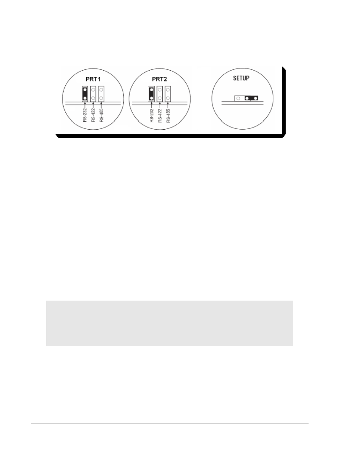
2.4 Jumper Locations and Settings
Each module has three jumpers:
Setup
ProSoft Technology, Inc. Page 7 of 264
March 12, 2014
Page 14
Preparing the MVI56E-LDM Module ControlLogix Platform ♦ "C" Programmable
Developer's Manual Linux Application Development Module
Port 1
Port 2
2.4.1 Setup Jumper - MVI56E
The Setup Jumper acts a write protection for the module's firmware. In "writeprotected" mode, the setup pins are not connected which prevents the module's
firmware from being overwritten.
The module is shipped with the Setup Jumper OFF. If you need to update the
firmware or run a module rescue (recovery), apply the setup shunt over both
pins.
2.4.2 Port 1 and Port 2 Jumpers MVI56E
These jumpers, located at the bottom of the module, configure the port settings
to RS-232, RS-422, or RS-485. By default, the jumpers for both ports are set to
RS-232.
2.5 Setting Up a Connection with the Module
If you have not already done so, please install and configure your ControlLogix
processor and power supply. Refer to the Rockwell Automation product
documentation for installation instructions.
Warning: You must follow all safety instructions when installing this or any other electronic
devices. Failure to follow safety procedures could result in damage to hardware or data, or even
serious injury or death to personnel. Refer to the documentation for each device you plan to
connect to verify that suitable safety procedures are in place before installing or servicing this
device.
After verifying proper jumper placement, insert the module into the ControlLogix
chassis. Use the same technique recommended by Rockwell Automation to
remove and install ControLogix modules.
Page 8 of 264 ProSoft Technology, Inc.
March 12, 2014
Page 15
ControlLogix Platform ♦ "C" Programmable Preparing the MVI56E-LDM Module
Linux Application Development Module Developer's Manual
2.5.1 Installing the Module in the Rack
You can install or remove ControlLogix system components while chassis power
is applied and the system is operating. However, please note the following
warning.
Warning: When you insert or remove the module while backplane power is on, an electrical arc
can cause personal injury or property damage by sending an erroneous signal to your system's
actuators. This can cause unintended machine motion or loss of process control. Electrical arcs
may also cause an explosion they occur in a hazardous environment. Verify that power is
removed, or that the area is non-hazardous before proceeding. Repeated electrical arching
causes excessive wear to contacts on both the module and its mating connector. Worn contacts
may create electrical resistance that can affect module operation.
Align the module with the top and bottom guides, and then slide it into the rack
until the module is firmly seated against the backplane connector.
With a firm, steady push, snap the module into place. Ensure that the holding
clips on the top and bottom of the module are securely in the locking holes of the
rack.
Make a note of the slot location. Slot numbers are identified on the green circuit
board (backplane) of the ControlLogix rack.
Turn power On.
ProSoft Technology, Inc. Page 9 of 264
March 12, 2014
Page 16
Preparing the MVI56E-LDM Module ControlLogix Platform ♦ "C" Programmable
Developer's Manual Linux Application Development Module
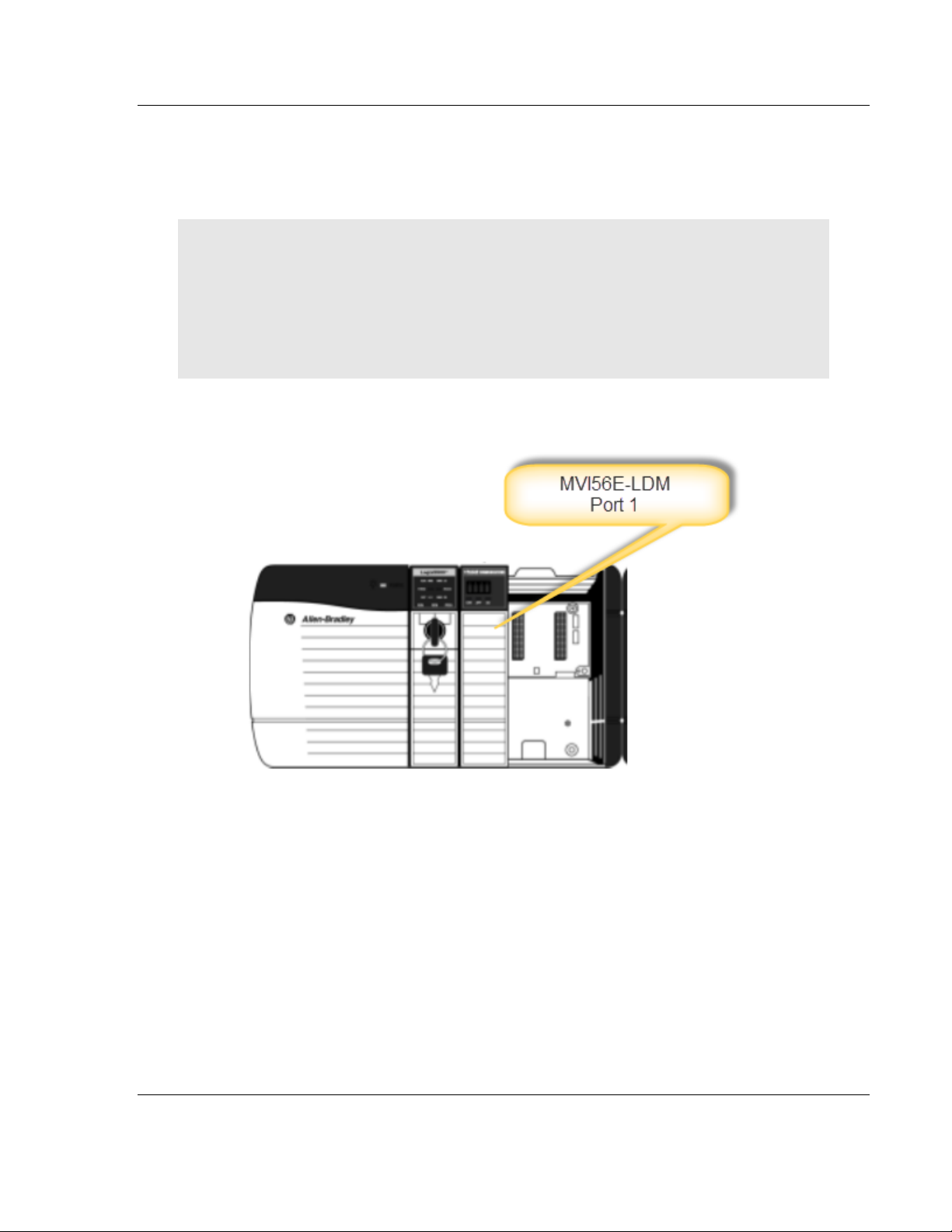
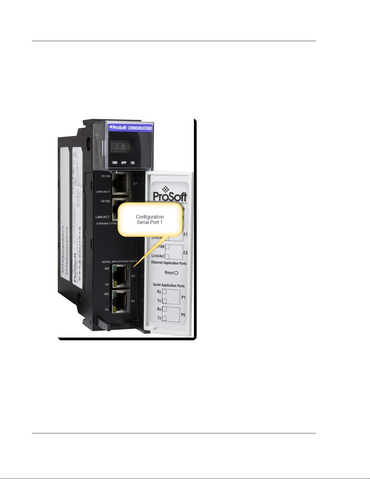
2.5.2 Making Configuration Port Connections
You can communicate with the module via RS232 through the Console or
through one of the Ethernet ports using Telnet.
RS-232 Console
You access the Console through Serial Port 1. As a default, the RS-232 Console
port is "enabled". You can "disable" or "enable" this port. Refer to Enabling and
Disabling the Console Port in the next section.
1 Connect the RJ45 end of an RJ45 - DB9m cable (Cable 14) to the Serial Port
1 of the module.
2 Connect one end of the Null Modem Cable (Cable 15) to the DB9m end
Cable 14.
3 Connect the other end of Cable 15 (null modem cable) to your a serial port on
your PC or laptop.
Page 10 of 264 ProSoft Technology, Inc.
March 12, 2014
Page 17
ControlLogix Platform ♦ "C" Programmable Preparing the MVI56E-LDM Module
Linux Application Development Module Developer's Manual
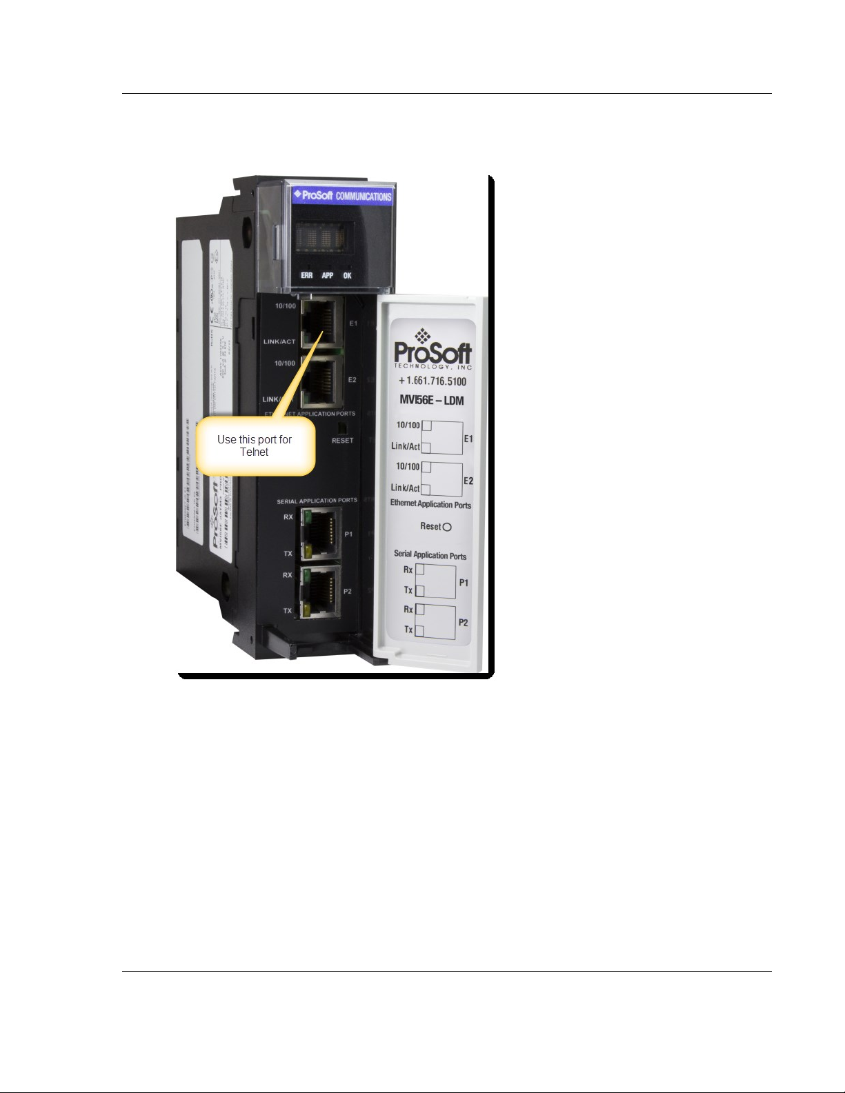
Ethernet Port
The module contains a Telnet client which is accessed through Ethernet Port 1
(E1) as shown.
Connect an Ethernet RJ45 cable to the E1 port of the module and the other end
to the network switch.
ProSoft Technology, Inc. Page 11 of 264
March 12, 2014
Page 18
Preparing the MVI56E-LDM Module ControlLogix Platform ♦ "C" Programmable
Developer's Manual Linux Application Development Module
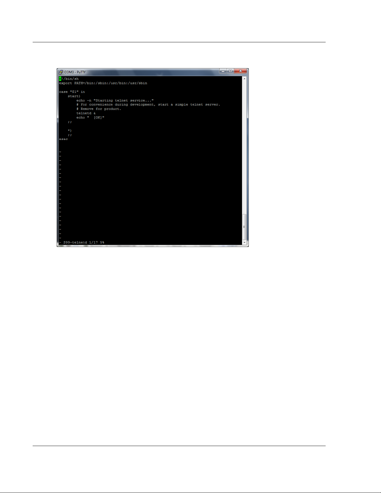
You can also "enable" or "disable" the Telnet port. Open a Putty session as
shown below. The following screenshot shows the Telnet Port "enabled"
To disable the Telnet port...
Page 12 of 264 ProSoft Technology, Inc.
March 12, 2014
Page 19
ControlLogix Platform ♦ "C" Programmable Preparing the MVI56E-LDM Module
Linux Application Development Module Developer's Manual
cd\etc\init.d\S99-telnetd.
ProSoft Technology, Inc. Page 13 of 264
March 12, 2014
Page 20
Preparing the MVI56E-LDM Module ControlLogix Platform ♦ "C" Programmable
Developer's Manual Linux Application Development Module
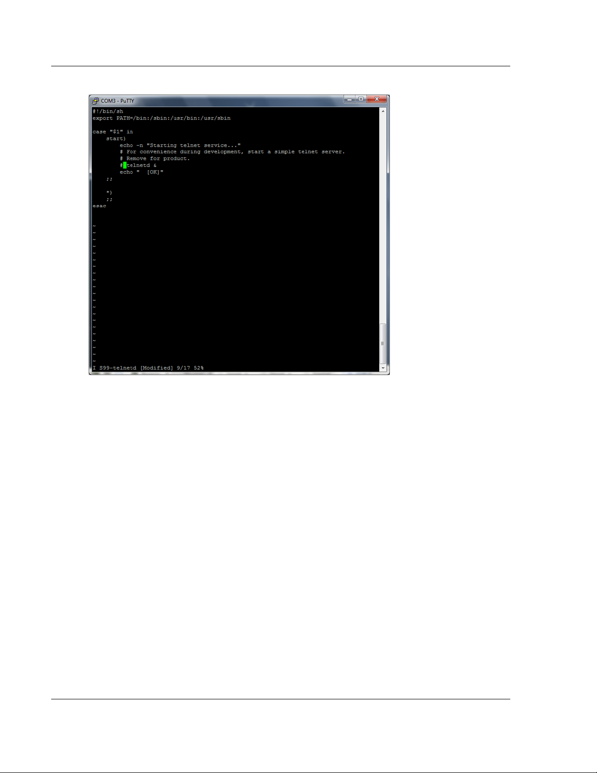
Comment out the telnetd file.
To enable the port, simply un-comment the same line.
Page 14 of 264 ProSoft Technology, Inc.
March 12, 2014
Page 21
ControlLogix Platform ♦ "C" Programmable Preparing the MVI56E-LDM Module
Linux Application Development Module Developer's Manual
2.6 Enabling and Disabling the Console Port
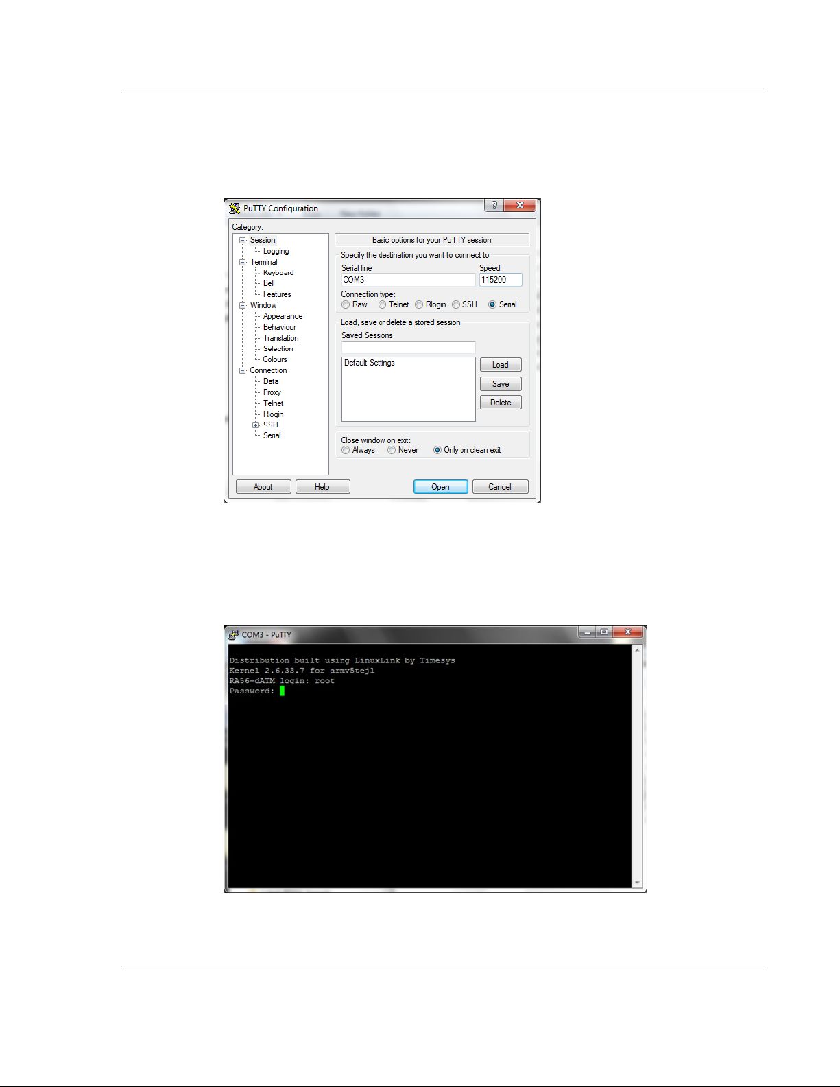
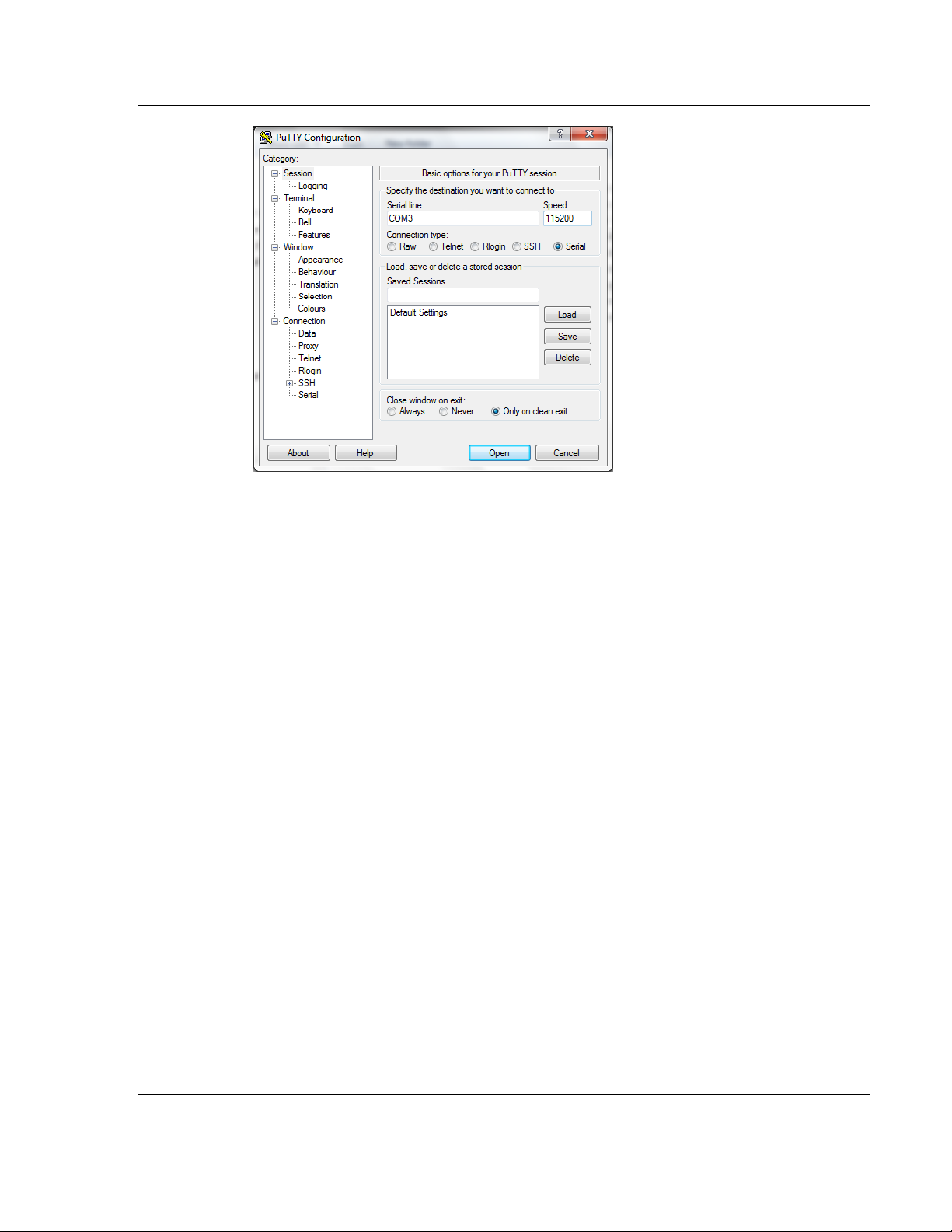
Establish a connection to the module. In the following example, PUTTY is being
used.
1. Open PUTTY.
Set the Speed to 115200
Set the appropriate COM port
Ensure that the Connection Type is set to Serial.
2. Click Open. The Putty session opens.
3. Enter your login and password. RA56-daTM login: root, Password:
password.
ProSoft Technology, Inc. Page 15 of 264
March 12, 2014
Page 22
Preparing the MVI56E-LDM Module ControlLogix Platform ♦ "C" Programmable
Developer's Manual Linux Application Development Module
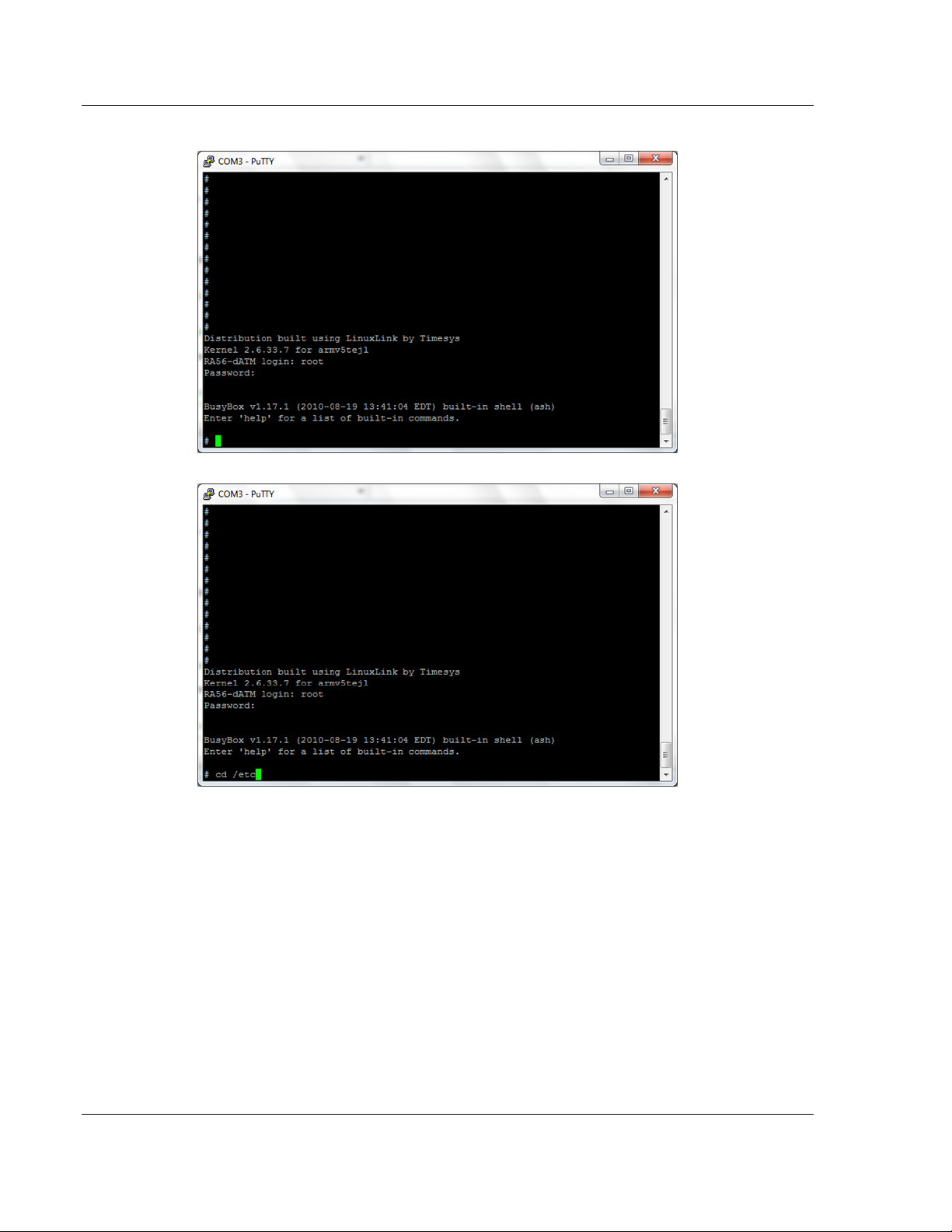
The following appears:
4. cd to /etc.
Page 16 of 264 ProSoft Technology, Inc.
March 12, 2014
Page 23
ControlLogix Platform ♦ "C" Programmable Preparing the MVI56E-LDM Module
Linux Application Development Module Developer's Manual
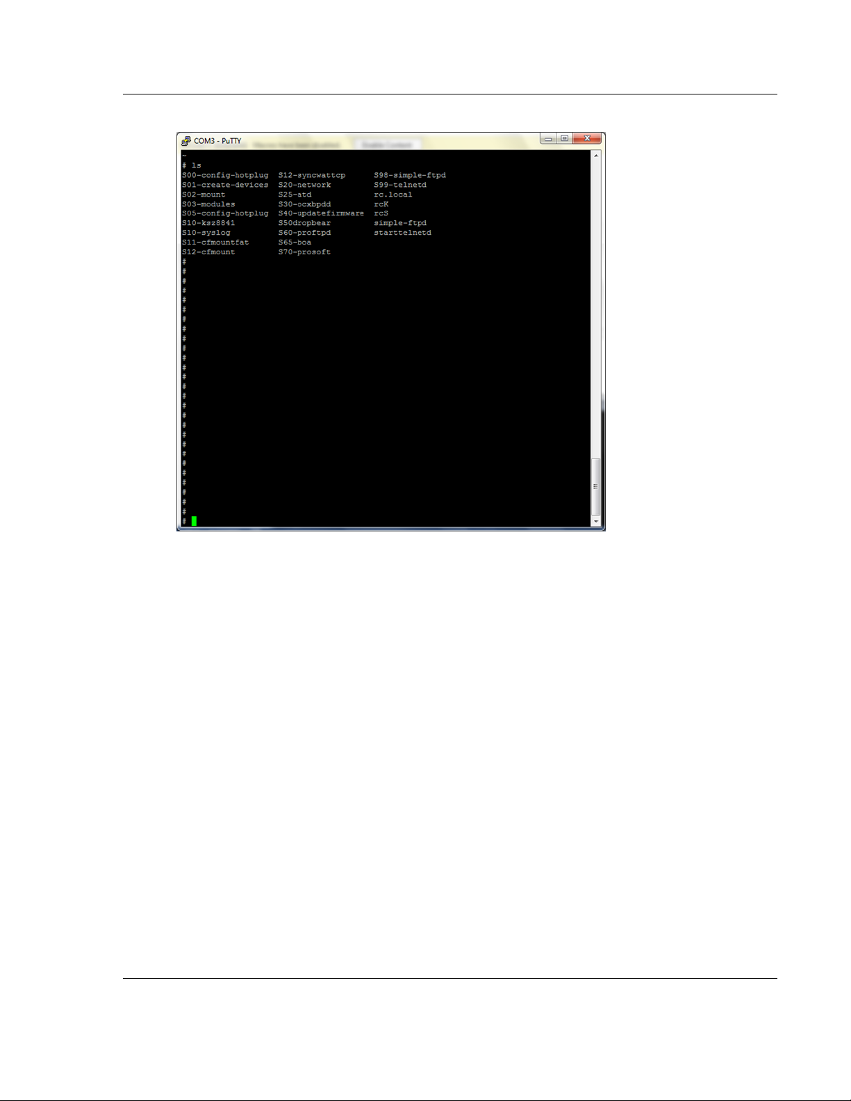
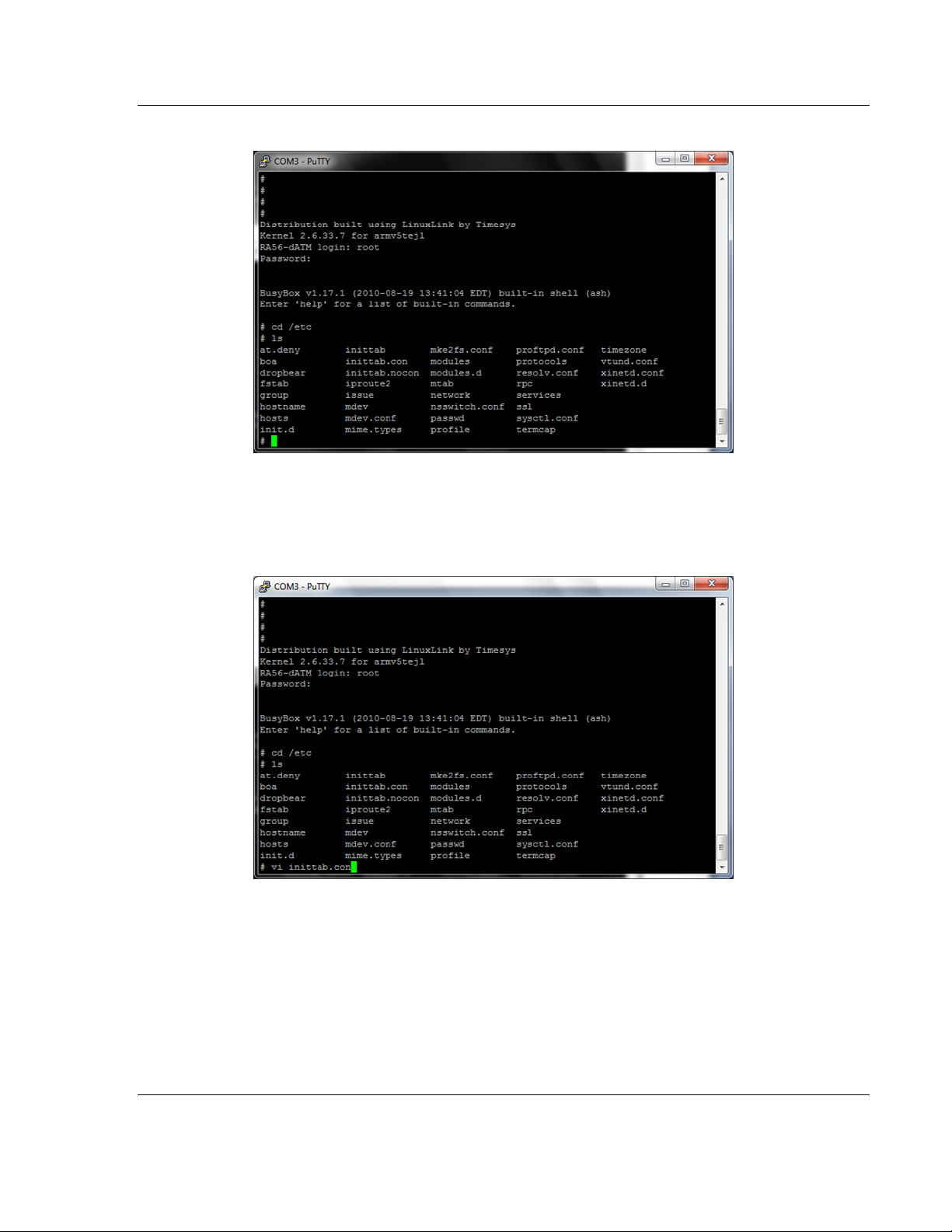
5. Type ls. The following appears:
There are two files used to enable or disable the console port:
inittab.con - configures the console
inittab.nocon - configures no console
To enable the console.....
1. Open the inittab.con file.
ProSoft Technology, Inc. Page 17 of 264
March 12, 2014
Page 24
Preparing the MVI56E-LDM Module ControlLogix Platform ♦ "C" Programmable
Developer's Manual Linux Application Development Module
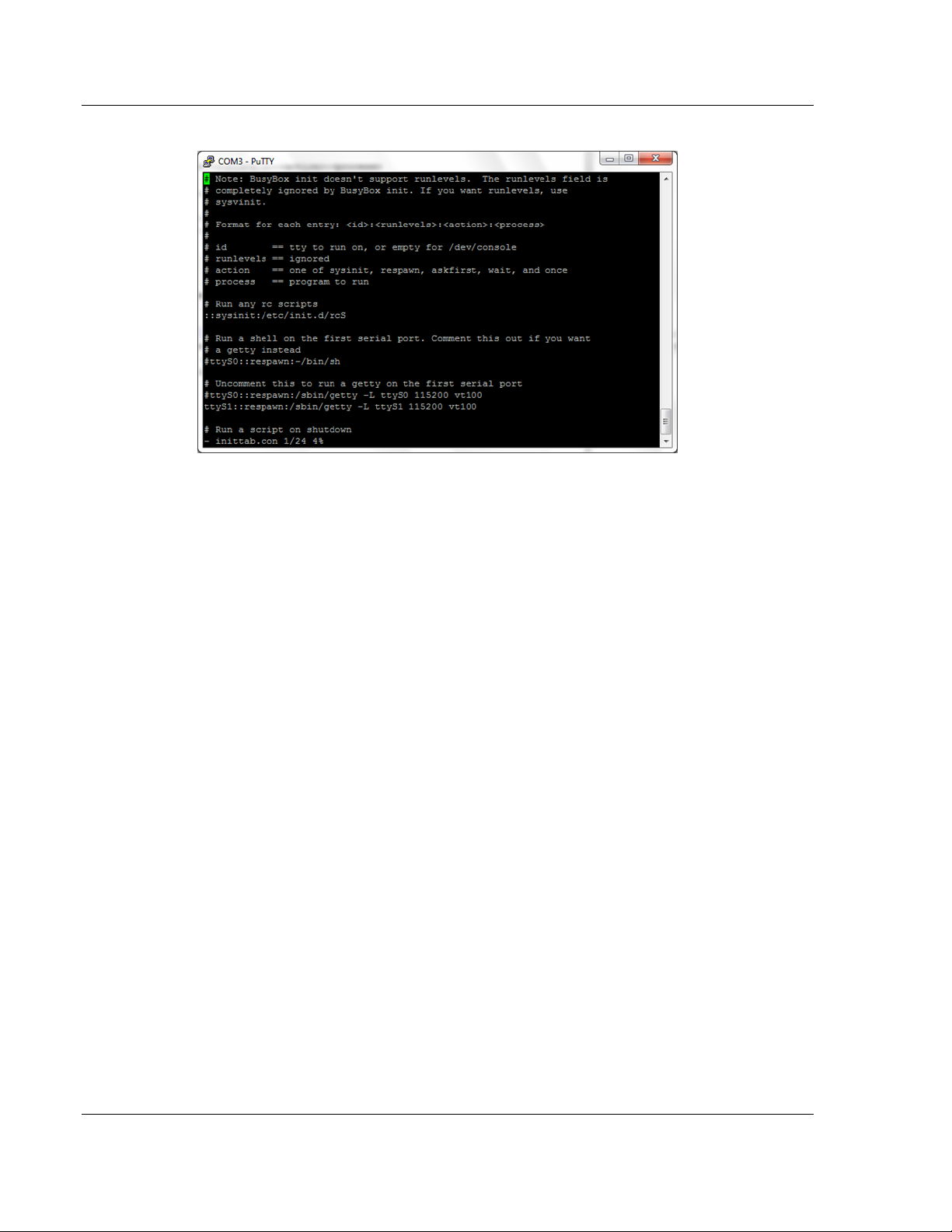
The file content is shown:
2. Copy inittab.con file to the inittab file.
3. Save the file and reboot the module.
To disable the console...
1. Copy inittab.nocon file to the inittab file.
2. Save the file and reboot the module.
2.7 Establishing Module Communication
Ensure that the module is firmly seated in the rack and that the cables described
in the previous section are secure. Ensure that power is applied.
Note: If you require information on cables and port pinouts, please refer to the
section entitled Cable Connections (page 209) at the end of the manual.
RS-232 Console
If you are connected to Serial Port 1 (P1), establish communications with the
module using the following procedure.
Note: The following procedure uses PUTTY to establish communications. You
can use whatever program you desire.
1. Open Putty
Page 18 of 264 ProSoft Technology, Inc.
March 12, 2014
Page 25
ControlLogix Platform ♦ "C" Programmable Preparing the MVI56E-LDM Module
Linux Application Development Module Developer's Manual
Set the Speed to 115200
Set the appropriate COM port
Ensure that the Connection Type is set to Serial.
2. Click Open. The Putty session opens.
3. Enter your login and password:
RA56-daTM login: root
Password: password
Ethernet (Telnet)
You can communicate with the module through Ethernet Port 1 (E1) using
Telnet.
The Ethernet Port (E1) is programmed with eth0 set to IP 192.168.0.250 and a
Subnet Mask of 255.255.255.0. In order for your PC or laptop to talk to the
module, your PC or Laptop must be on the same subnet as the module. This
means that you must temporarily change the IP address and subnet mask on
your PC or laptop to match that of the module. You can then change the
module's IP address to match your needs.
1. Change the IP Address of your PC or Laptop so it matches the subnet of
the module.
ProSoft Technology, Inc. Page 19 of 264
March 12, 2014
Page 26
Preparing the MVI56E-LDM Module ControlLogix Platform ♦ "C" Programmable
Developer's Manual Linux Application Development Module
2. Ensure that an Ethernet cable is connected to Ethernet Port 1 (E1) of the
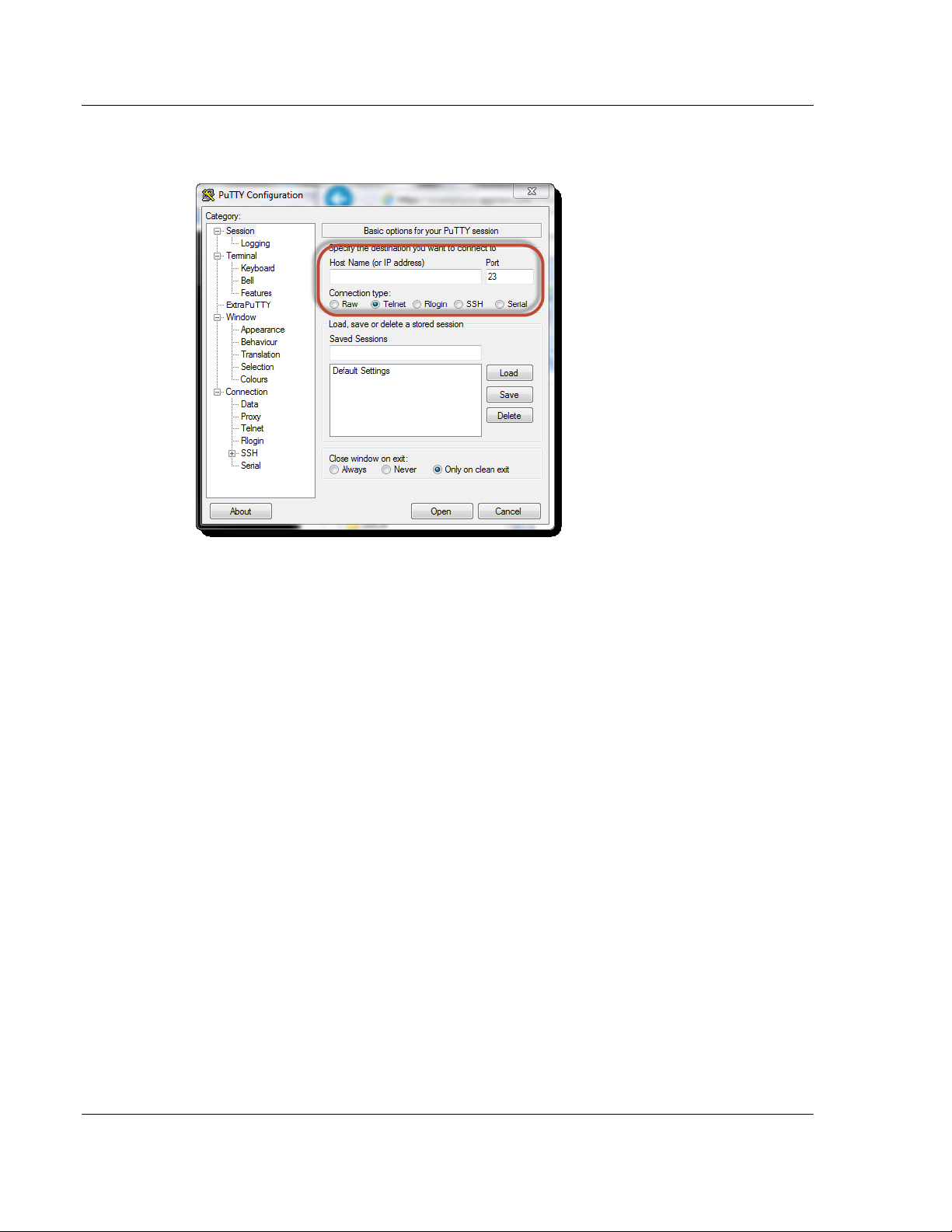
module.
3. Use a program such as Putty to Telnet into the module.
Select Telnet as the Connection type.
Enter the IP address (192.168.0.250)
Port 23 should appear as the Port number.
4. Click the Open button to establish a connection.
5. Login into the module.
There are two methods used to change the module's IP address. One is
temporary for use in cases where you want to change the address long enough
to make a quick change. The other is more permanent in that the module is
already programmed and is ready for full deployment.
Temporary IP Address Change
At the Linux prompt, type:
ifconfig eth0 x.x.x.x -- This changes the IP address of the Ethernet E1 port
ifconfig eth1 x.x.x.x -- This changes the IP address of the Ethernet E2 port.
Permanent IP Address Change
At the Linux prompt, type:
cd ../etc/network -- changes the directory to network
vi interfaces -- opens the interfaces file for ethernet assignment in a vi editor
iface eth0 inet static
address 192.168.0.250
network 192.168.0.0
netmask 255.255.255.0
broadcast 192.168.0.255
# gateway 192.168.0.1
Page 20 of 264 ProSoft Technology, Inc.
March 12, 2014
Page 27

ControlLogix Platform ♦ "C" Programmable Preparing the MVI56E-LDM Module
Linux Application Development Module Developer's Manual
auto eth1
iface eth1 inet static
address 192.168.1.250
network 192.168.1.0
netmask 255.255.255.0
broadcast 192.168.1.255
# gateway 192.168.1.1
Using the vi editor, edit the file to change the address.
Save the file.
For help on using the vi editor to write and save the file, refer to
http://www.lagmonster.org/docs/vi.html http://www.lagmonster.org/docs/vi.html.
Change the IP address of your PC back to the original subnet.
Telnet to the new IP Address of the module.
2.8 Module Rescue
In the event that it becomes necessary to revert the MVI56E-LDM module back
to its initial out-of-the-box state, there are a number of methods you can use
depending on the condition of the module.
The Rescue process re-installs all of the Operation System commands and
configurations to their original defaults. The files deleted during the rescue
process are the startup scripts in the /etc/init.d path since extra scripts in this
path are automatically executed by the operating system on startup and may
cause problems. All other files may be overwritten to the initial state of the
device. Extra files are not deleted.
If the web pages and services for the module have been altered, it may not be
possible to use the web-based rescue.
Prep and Establish Communications
Place the onboard setup jumper to the installed state.
Ethernet Communication
If the IP address is known, change the network mask and IP of a connected PC
to something compatible.
For example, if the MVI56E-LDM is configured with the default IP address
(192.168.1.250) and network mask (255.255.255.0), the the PC should have the
same IP4 network mask and an IP address in the 192.168.1.xxx subnet.
Note that IP addresses must be unique on the network. If in doubt, create a
physical network consisting of only the MVI56E-LDM and the PC.
Serial Communication
If the IP address if the MVI56E-LDM module is unknown, communication may be
established through the serial configuration port (i.e., Port 1 (upper port)). Use
Telnet or a similar terminal program to communicate with the module. Default
baud is 115,200, 8 data bits,1 stop bit, No Parity, xon/xoff flow control.
Use the following username and password:
Username: root
ProSoft Technology, Inc. Page 21 of 264
March 12, 2014
Page 28

Preparing the MVI56E-LDM Module ControlLogix Platform ♦ "C" Programmable
Developer's Manual Linux Application Development Module
Password: password
From the shell prompt, run ifconfig to determine the Ethernet IP address and
network mask of device "eth0". Then follow the previous steps to establish
communication via Ethernet.
Web-based Rescue
The web page for the MVI56E-LDM module contains a command to recover the
module on the left-side of the page.
Open the web page for the module by entering the IP address of the module in
the address bar. (your PC/workstation should have an IP address and the same
sub-network).
On the left-side of the page, under Functions, click on Rescue Module. Follow
the instructions to set the module back to its default state.
Note: Most loaded components are left intact by this operation so it may be necessary to make
enough room on the module for the rescue to work. In addition, the Setup Jumper must be in place
for the rescue to function properly.
Manual Rescue
If the default web pages are unavailable, a manual rescue may be required.
Perform the following steps to manually return the module to its default state:
1. Establish a terminal session to the module using either the Serial or
Ethernet port.
2. Ensure that the following file exists:
/backup/systemrestore.tgz
3. Run the following command to remove any startup scripts that may be
interfering with the bootup process:
rm -f /etc/init.d/*
4. Restore the configuration and executables using the following command:
tar -xzf /backup/systemrestore.tgz -C /
5. If successful, reboot the system.
Page 22 of 264 ProSoft Technology, Inc.
March 12, 2014
Page 29

ControlLogix Platform ♦ "C" Programmable Development Environment
In This Chapter
Setup ..................................................................................................... 23
Using Eclipse ......................................................................................... 27
Linux Application Development Module Developer's Manual
3 Development Environment
The MVI56E-LDM development tools run under Linux. In order to run these tools
on a Windows-based machine, you must run a Virtual Machine that hosts the
Linux Operating System.
VMware provides a virtual machine player used to host the Linux Operating
System. You can get it at:
https://my.vmware.com/web/vmware/downloads.
3.1 Setup
The file Debian6VM.zip is located on the ProSoft Product DVD shipped with the
module.
1. Copy this file to the VM Player image ico directory (VMware > VMware
2. Uncompress Debian6VM.zip into this directory.
Player > ico).
ProSoft Technology, Inc. Page 23 of 264
March 12, 2014
Page 30
Development Environment ControlLogix Platform ♦ "C" Programmable
Developer's Manual Linux Application Development Module
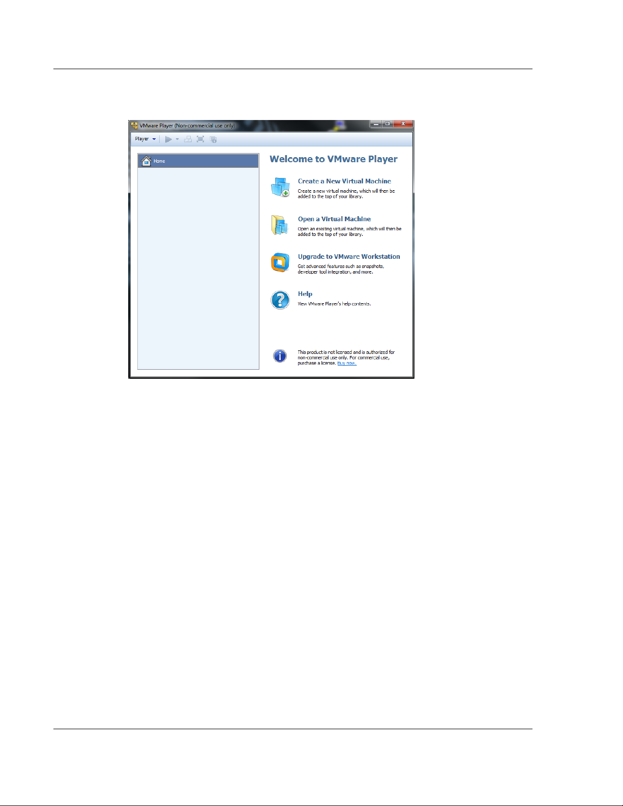
3. Start the VM Player by double-clicking on its icon.
4. Select "Open a Virtual Machine".
Page 24 of 264 ProSoft Technology, Inc.
March 12, 2014
Page 31

ControlLogix Platform ♦ "C" Programmable Development Environment
Linux Application Development Module Developer's Manual
5. Navigate to the Debian6VM file and click on Debian6VM.vmx. The image
icon appears in the left window.
6. Double-click on the image icon. The following screen appears:
ProSoft Technology, Inc. Page 25 of 264
March 12, 2014
Page 32

Development Environment ControlLogix Platform ♦ "C" Programmable
Developer's Manual Linux Application Development Module
7. Click "Play virtual machine". A dialog appears asking if the virtual
machine has been moved or copied. Select "I copied it".
8. After the image loads, the VMware Player prompts you for a username
and password.
Username: user
Password: password
The home screen appears.
Page 26 of 264 ProSoft Technology, Inc.
March 12, 2014
Page 33

ControlLogix Platform ♦ "C" Programmable Development Environment
Linux Application Development Module Developer's Manual
3.2 Using Eclipse
Eclipse is an Integrated Development Environment (IDE) used in the Linux
environment primarily to edit source code. Full documentation and downloads
are available at www.eclipse.org http://www.eclipse.org.
When you initially start Eclipse, you must select a workspace. Select the default:
/home/user/workspace.
To start Eclipse...
1. Double-click on the Eclipse icon.
2. When the Workspace Launcher appears, choose the default.
3. Click OK.
The default workspace is pre-populated with sample programs, makefiles, and
scripts. Building one of the samples is the recommended way to become familiar
with the environment and build process.
3.2.1 Building a Project
Building and using a sample application consists of:
Compiling and Linking
Creating a downloadable image
Downloading an image to the target device
Compiling and Linking
1. Start the Linux (Debian) virtual machine in the VM Player.
ProSoft Technology, Inc. Page 27 of 264
March 12, 2014
Page 34

Development Environment ControlLogix Platform ♦ "C" Programmable
Developer's Manual Linux Application Development Module
2. Open a Bash Shell window by clicking on the Bash Shell icon on the main
page.
3. Once in the shell, change the directory to one of the samples. In this
case, change the directory to get to the LED_sample program.
cd /workspace/mvi56e-ldm/src/LDM/led_sample$ as shown below:
4. To recompile and link, simply type "make". In this case, the executable is
up to date and nothing needs to be done.
5. If the source is changed, "make" detects the newer time on the source file
and rebuilds the application. In the following example, the Touch Utility is
used to cause the date of the file led_sample.c to be updated as if the file
had been changed and "make" is re-invoked. Make detects this change,
recompiles and re-links the application.
Downloading the Application
There are two ways to place the application on the target:
FTP
Firmware Update Feature
Page 28 of 264 ProSoft Technology, Inc.
March 12, 2014
Page 35

ControlLogix Platform ♦ "C" Programmable Development Environment
Linux Application Development Module Developer's Manual
FTP Transfer
For FTP Transfer, use any ftp transfer program such as FileZilla (https://filezillaproject.org/ https://filezilla-project.org/) from the Windows environment.
Use FileZilla to connect to the target by specifying the MVI56E-LDM's IP
address.
Download the application image to the desired directory on the LDM using the ftp
transfer program.
Since Windows does not have the same detailed permissions as Linux, you will
have to change the file permissions on the application once on the target. Use
the command chmod a+x filename which adds the execute attribute to the
application.
Creating a Download Image
An image contains all of the application-specific components required for the
user application. This includes the executable(s), application-specific shared
libraries, scripts, web pages, and data files. It does not contain the operating
system or common components that are already on the target device.
The image is a compressed tar file of the application components. Once created,
use the device's web page to download the firmware upgrade. The tar file name
is specified in "Image Contents". In the sample image, the firmware files is
'firmware/mvi56e-ldm.firmware revision date'. This firmware file is downloaded to
the directory /psfttmp on the target device. Upon system restart, the system
startup scripts unpack the tar file into the psfttmp directory. The script
/psfttmp/install is executed to move the component files into their final
destination.
A sample install file is included with the sample applications.
The first step is to create all of the components that will be part of the system.
This mainly involves compiling and linking executables and shared libraries.
Modify any web pages and data files that will be needed. Lastly, update the
install script.
Image Contents
Each component file to be included in the image is listed in the file
'imagecontents' found in the build directory structure for the specific application.
This file contains header information about the image and a list of entries
describing the files to be added to the image. The format of the entry is as
shown:
Add source destination file permissions
where the source file is the path to the file to be included. The destination file is
the full path name of the file on the destination on the target device. Permissions
are the Linux style permissions of the file on the destination.
For example, a line to add the LED_Sample application looks like:
Add ../../src/ldm/led_sample/Release/Led_Sample /psft/sample/Led_Sample
rwxrwxr-x
ProSoft Technology, Inc. Page 29 of 264
March 12, 2014
Page 36

Development Environment ControlLogix Platform ♦ "C" Programmable
Developer's Manual Linux Application Development Module
Since builds occur in /home/usr/workspace/mvi56e-ldm/build/LDM, source paths
are relative to this directory to simplify moving to a new directory.
Follow the sample provided to create a complete imagecontents file.
Install Script
Before creating the image, an 'install' script must be created and added to the
firmware package. As noted above, the firmware package will be downloaded
into the /psfttmp directory on the device. The 'install' script will copy the files in
psfttmp to their final destination on the target device. The 'install' script can be
used to make backups of the current directory contents before they are
overwritten. The LDM sample install script in build/LDM/scripts illustrates how to
do this.
Creating the Image
In a Linux shell, change the directory to the ...build/LDM directory.
Run python with the following command:
python createimage.py
The python script createimage.py reads and acts on the imagecontents file and
creates a new firmware image in the directory .../build/LDM/firmware.
Note: The script 'build.sh' will compile/link all libs and executables and then
invoke python to create the firmware image.
Page 30 of 264 ProSoft Technology, Inc.
March 12, 2014
Page 37

ControlLogix Platform ♦ "C" Programmable Development Environment
Linux Application Development Module Developer's Manual
Downloading the Image via Web Page
1. Ensure that the Setup Jumper is on. See Setup Jumper in this manual.
2. Navigate to the module homepage using a Web browser.
3. Select Firmware Upgrade. The Update page opens.
ProSoft Technology, Inc. Page 31 of 264
March 12, 2014
Page 38

Development Environment ControlLogix Platform ♦ "C" Programmable
Developer's Manual Linux Application Development Module
4. Click on the Continue with Update button, and then select the firmware
file to be downloaded.
5. Click on the Update Firmware button and wait for the module to reboot.
During reboot, the compressed file is un-"tar" ed and the install script is
run to move the component files to their final destination.
Note: The IP address will revert to the default after reboot. This is a very
common problem.
Page 32 of 264 ProSoft Technology, Inc.
March 12, 2014
Page 39

ControlLogix Platform ♦ "C" Programmable Understanding the MVI56-LDM API
In This Chapter
API Library - MVI56E ............................................................................. 33
MVI56E-LDM Development Tools ......................................................... 35
CIP API Functions ................................................................................. 36
Backplane Device Driver ....................................................................... 36
Linux Application Development Module Developer's Manual
4 Understanding the MVI56-LDM API
The MVI56E LDM CPI API Suite allows software developers to access the
ControlLogix backplane without requiring detailed knowledge of the module’s
hardware design. The MVI56E-LDM API Suite consists of three distinct
components; the backplane device driver, the backplane interface engine, and
the API library.
Applications for the MVI56E-LDM module may be developed using industrystandard Linux programming tools and the CPI API library.
This section provides general information pertaining to application development
for the MVI56E-LDM module.
4.1 API Library - MVI56E
The API provides a library of function calls. The library supports any
programming language that is compatible with the 'C' calling convention. The
API library is a dynamic library that must be linked with the application to create
the executable program>
Note: The following compiler versions are tested and known to be compatible with the MVI56E
module API:
CNU C/C++ V4.4.4 for ARM9
4.1.1 Header File
A header file is provided along with the API library. This header file contains API
function declarations, data structure definitions, and constant definitions. The
header file is in standard 'C' format. Header files for the CIP API are ocxbpapi.h
and ocxtagdb.h.
4.1.2 Sample Code
Sample applications are provided to illustrate the usage of the API functions. Full
source for the sample application is included, along with make files to build the
sample programs.
ProSoft Technology, Inc. Page 33 of 264
March 12, 2014
Page 40

Understanding the MVI56-LDM API ControlLogix Platform ♦ "C" Programmable
TagName
Single tag
Array[11]
Single dimensioned array element
Array[1,3]
Two dimensional array element
Developer's Manual Linux Application Development Module
4.1.3 Specifying the Communications Path
To construct a communications path, enter one or more path segments that lead
to the target device. Each path segment takes you from one module to another
module over the ControlBus backplane or over a ControlNet or Ethernet network.
Each path contains:
p:x, {s, c, t} :y
where
p:x specifies the device's port number to communicate through.
where x is:
1 - backplane from any 1756 module
2 - ControlNet port from a 1756-CNB module
3 - Ethernet port from a 1756-ENET module
, - separates the starting point and ending point of the path segment.
{s, c, t} :y specifies the address of the module you are going to.
where
s:y - ControlBus backplane slot number
c:y - ControlNet network node number (1 to 99 decimal)
t:y - Ethernet network IP address (for example, 10.0.104.140)
If there are multiple path segments, separate each segment with a comma (,).
Examples
To communicate from a module in slot 4 of the ControlBus backplane to a
module in slot 0 of the same backplane:
p:1, s:0
To communicate from a module in slot 4 of the ControlBus backplane, through a
1756-CNB in slot 2 at node 15, over ControNet to a 1756-CNB in slot 4 at node
21 to a module in slot 0 of a remote backplane"
p:1, s:2, P:2, c:21, p:1, s:0
To communicate from a module in slot 4 of the ControlBus backplane, through a
1755-ENET in slot 2 over Ethernet, to a 1756-ENET (IP address of 10.0.104.42)
in slot 4, to a module in slot 0 of a remote backplane:
p:1, s:2, p:2, t:10.0.104.42, p:1, s:0
4.1.4 ControlLogix Tag Naming Conventions
ControlLogix tags fall into two categories; controller tags and program tags.
Controller Tags have global scope. To access a controller scope tag, you only
need to specify the tag controller name. For example:
Page 34 of 264 ProSoft Technology, Inc.
March 12, 2014
Page 41

ControlLogix Platform ♦ "C" Programmable Understanding the MVI56-LDM API
Array[1, 2, 3]
Three dimensional array element
Structure.Element
Structure element
StructureArray[1].Element
Single element of an array of structures
PROGRAM:MainProgram.TagName
Tag "TagName in program called "MainProgram"
PROGRAM:MainProgram.Array[11]
An array element in program "MainProgram"
PROGRAM:MainProgram.Structure.Element
A Structure Element in program "MainProgram"
Linux Application Development Module Developer's Manual
Program Tags are tags declared in a program and scoped only within the
program in which they are declared. To correctly address a Program Tag, you
must specify the identifier "PROGRAM:" followed by the program name. A dot (.)
is used to separate the program name and the tag name.
PROGRAM:ProgramName.TagName
Rules
A tag name can contain up to 40 characters
A tag name must start with a letter or underscore ("_"). All other characters
can be letters, numbers or underscores.
Names cannot contain two contiguous underscore characters and cannot end
in with an underscore
Letter case is not considered significant
The naming conventions are based on the IEC-1131 Rules for Identifiers.
For additional information on ControlLogix CPU tag addressing, please refer to
the ControlLogix User Manual.
4.2 MVI56E-LDM Development Tools
An application that is developed for the MVI56E-LDM module must be executed
from the module’s Flash ROM disk. Tools are provided with the API to build the
disk image and download it to the module’s Config/Debug port.
ProSoft Technology, Inc. Page 35 of 264
March 12, 2014
Page 42

Understanding the MVI56-LDM API ControlLogix Platform ♦ "C" Programmable
Developer's Manual Linux Application Development Module
4.3 CIP API Functions
The CIP API communicates with the ControlLogix modules through the
backplane device driver. The following illustration shows the relationship
between the module application, CIP API, and the backplane driver:
4.4 Backplane Device Driver
The backplane device driver contains the functionality to perform CIP messaging
over the ControLogix backplane using the Midrange ASIC. The user application
interfaces with the backplane device driver through the CIP API library.
The backplane device driver for the MVI56E-LDM module is libocxbpeng.so.
The driver implements the following components and objects:
Page 36 of 264 ProSoft Technology, Inc.
March 12, 2014
Page 43

ControlLogix Platform ♦ "C" Programmable Understanding the MVI56-LDM API
Linux Application Development Module Developer's Manual
All data exchange between the application and the backplane occurs through the
Assembly Object, using functions provided by the CIP API. The API includes
functions to register or unregister the object, accept or deny Class 1 schedule
connections requests, access scheduled connection data, and service
unscheduled messages.
ProSoft Technology, Inc. Page 37 of 264
March 12, 2014
Page 44

Understanding the MVI56-LDM API ControlLogix Platform ♦ "C" Programmable
Developer's Manual Linux Application Development Module
4.5 Sample Code
To help understand the use of the MVI56E-LDM module, a number of example
programs are provided with the module. These programs exist both as source
code in the development environment as well as executable programs in the
MVI56E-LDM module in the /psft/sample directory.
The sample programs can be built and downloaded to the MVI56E-LDM module.
Page 38 of 264 ProSoft Technology, Inc.
March 12, 2014
Page 45

ControlLogix Platform ♦ "C" Programmable Understanding the MVI56-LDM API
Linux Application Development Module Developer's Manual
4.6 Establishing a Console Connection
In order to run the Ethernet and Serial samples and tutorials, you must set up a
connection in order to efficiently communicate with the MVI56E-LDM.
ProSoft Technology, Inc. Page 39 of 264
March 12, 2014
Page 46

Understanding the MVI56-LDM API ControlLogix Platform ♦ "C" Programmable
Developer's Manual Linux Application Development Module
4.7 Physically Connect to the Module
In order to establish a console session between a PC and the MVI56E-LDM
module, you must physically connect your PC to the console serial port on the
module.
1. Plug in an RJ45 to DB9 cable on Port 1.
2. Connect the null modem cable to the DB9 end of the RJ45 to DB9 cable.
3. Connect the other end of the null modem cable to the appropriate serial
port (USB to Serial Converter) on the computer.
Page 40 of 264 ProSoft Technology, Inc.
March 12, 2014
Page 47

ControlLogix Platform ♦ "C" Programmable Understanding the MVI56-LDM API
Linux Application Development Module Developer's Manual
4.8 Configuring Serial Communication
Establish a connection to the module. In the following example, PUTTY is being
used.
Note: You can download PUTTY for free at
http://www.chiark.greenend.org.uk/~sgtatham/putty/download.html.
1. Open PUTTY.
Set the Speed to 115200
Set the appropriate COM port
Ensure that the Connection Type is set to Serial.
2. Click Open. The Putty session opens.
3. Enter your login and password. RA56-daTM login: root, Password:
password.
ProSoft Technology, Inc. Page 41 of 264
March 12, 2014
Page 48

Understanding the MVI56-LDM API ControlLogix Platform ♦ "C" Programmable
Developer's Manual Linux Application Development Module
Keep PUTTY open while you set up the ControlLogix5000 as described in the
next section.
Page 42 of 264 ProSoft Technology, Inc.
March 12, 2014
Page 49

ControlLogix Platform ♦ "C" Programmable Understanding the MVI56-LDM API
Linux Application Development Module Developer's Manual
4.9 Setting Up the ControlLogix 5000
Open the MVI56E-LDM.ACD program and change the appropriate chassis type
to match your hardware and firmware.
ProSoft Technology, Inc. Page 43 of 264
March 12, 2014
Page 50

Understanding the MVI56-LDM API ControlLogix Platform ♦ "C" Programmable
Developer's Manual Linux Application Development Module
Download MVI56_LDM.ACD file in the ControlLogix processor by choosing
Communications > Who Active > Download.
Page 44 of 264 ProSoft Technology, Inc.
March 12, 2014
Page 51

ControlLogix Platform ♦ "C" Programmable Understanding the MVI56-LDM API
Linux Application Development Module Developer's Manual
4.10 Sample Tutorials
The following sections describe how to run and understand the sample tutorials
provided with the module.
ProSoft Technology, Inc. Page 45 of 264
March 12, 2014
Page 52

Understanding the MVI56-LDM API ControlLogix Platform ♦ "C" Programmable
Developer's Manual Linux Application Development Module
4.11 Ethernet Sample
The Ethernet sample comes as two programs; a client, and a server. The server
waits for a client to request a connection, replies with the local time, and closes
the connection. The client is run with the IP4 address of the server. The client
opens a connection to the server, receives the response message, and prints the
message (the time on the server) to the console.
It is recommended that the server be run on one MVI56E-LDM module and the
client on another. Alternately, either of the programs could be ported to another
Linux environment. Attempting to run both programs on the same MVI56E-LDM
is not advised due to the complexity of IP routing.
Server Enet Sample
To run the Server Enet sample:
Open a command window using telnet or a similar terminal software on the PC
through a serial (P1) or Ethernet port.
Login as user: root, password: password.
The Ethernet port E1 is used to communicate with the client device. The server
and client devices must both be connected on the same IPv4 subnet.
Set the IPv4 address and mask of the first Ethernet port using the ifconfig
command.
To execute the sample:
From the default home directory /psft, type the command ./Server_Sample&.
The program runs as a background task. The server will wait forever processing
requests from clients.
While looking at the sample source, you'll see that the following occurs:
register sigquit_handler for four signals
check command line and print usage message if required
open the backplane using open_backplane()
initialize the LEDs on the front panel
call the function socket() to create a unnamed socket inside the kernel.
socket() returns an integer know as socket descriptor.
o The function takes domain/family as its first argument. For Internet family
of IPv4 addresses, use AF_INET.
o The second argument SOCK_STREAM specifies the type of connection to
use. In this case, a sequential, reliable two-way connection is desired
o The third argument selects the protocol to use. Generally, this is zero as
the system normally only has one protocol for each type of connection,
although it is possible to have multiple protocols for a connection type.
Zero tells the system to use the default protocol for the specified
connection. In this case, the default is TCP.
The send_buff and serv_addr variables are zeroed.
In preparation for the call to bind(), serv_addr is then set to the well known
port address SERVER_PORT_NUMBER, and any IP address. This allows a
connection to be accepted from any IP address as long as the well known
port is specified.
Page 46 of 264 ProSoft Technology, Inc.
March 12, 2014
Page 53

ControlLogix Platform ♦ "C" Programmable Understanding the MVI56-LDM API
Linux Application Development Module Developer's Manual
The call to the function bind() assigns the address specified in the structure
serv_addr to the socket created by the call to socket().
The call to the function listen() with second arguments as '10' specifies the
maximum number of client connections that the server will queue for this
listening socket.
The call to listen() makes this socket a functional listening socket.
Code enters an infinite while loop in which:
o the call to accept() puts the server to sleep waiting for an incoming client
request. When a request is received, and the three-way TCP handshake
is complete, accept() wakes up and returns the socket description
representing the client socket.
o time() is called to read the current system time
o Snprintf is used to pu the time into the send buffer in a human-readable
format
o write() is then called to send formatted time to the client
o close() is then used to close the connection to the client
o sleep() is invoked to yield the processor for 1 second
Client ENetSample
To run the Client Enet sample:
1 Open a command window using telnet or a similar terminal software on the
PC through a serial (P1) or Ethernet port.
2 Login as user: root, password: password.
The Ethernet port E1 is used to communicate with the server device. The server
and client devices must both be connected on the same IPv4 subnet.
Set the IPv4 address and mask of the first Ethernet port using the ifconfig
command.
To execute the sample:
From the default home directory /psft, type the command ./Client_Sample
ip.address.of.server to run the program. The IP address of the server node
must be provide so the server will know which node is executing the server
program. The client will send a connection request to the server, print the
response from the server to the console, and then exit.
While looking at the the sample source, you'll see that the following occurs:
register sigquit_handler for four signals
check command line and print usage message if required
open the backplane using open_backplane()
initialize the LEDs on the front panel
create a socket with a call to the socket() function
initialize the server address (serv_addr) structure:
indicate that an IPv4 address is going to be used with AF_INET
set the destination port as the well known port SERVER_PORT_NUMBER
Convert the string version of the server IP address to binary with inet_pton()
After changing the front panel display to run, connect() is called to create the
TCP connection to the server
ProSoft Technology, Inc. Page 47 of 264
March 12, 2014
Page 54

Understanding the MVI56-LDM API ControlLogix Platform ♦ "C" Programmable
Developer's Manual Linux Application Development Module
When the sockets are connected, the server sends the date and time from
the server as a message back to the clients. The client then uses the read()
function to receive the buffer of data and prints the contents to the console.
Page 48 of 264 ProSoft Technology, Inc.
March 12, 2014
Page 55

ControlLogix Platform ♦ "C" Programmable Understanding the MVI56-LDM API
Linux Application Development Module Developer's Manual
4.12 Serial Sample
To run the Serial sample:
1 Open a command window using telnet or a similar terminal software on the
PC through a serial (P1) or Ethernet port.
2 Login as user: root, password: password.
The second serial port (P2) will be used for the communication sample.
To execute the sample:
1 From the default home directory /psft, type the command ./Serial_Sample&.
The program runs as a background task.
While looking at the sample source, you'll see that the following occurs:
register sigquit_handler for four signals
check command line and print usage message if required
open the backplane using open_backplane()
Read the serial configuration jumpers and make sure that the second serial
port is configured for RS232.
Open the serial port using the open_serial_port() function.
Opens the serial device by calling open()
Reads current serial port attributes using tcgetaddr()
Configures serial port attributes. cfsetispeed() and cfsetispeed() set the
baud rate. tcsetattr() is then used to set the remaining attributes.
Initialize LEDs on the front panel
Changes the front panel display to "Run"
Enters a for loop which transmits a test string one character at a time by
calling write() and then sleeping for 500 msec using OCXcip_Sleep()
Closes the serial driver connection using close().
ProSoft Technology, Inc. Page 49 of 264
March 12, 2014
Page 56

Understanding the MVI56-LDM API ControlLogix Platform ♦ "C" Programmable
Developer's Manual Linux Application Development Module
4.13 Led_Sample
The LED Sample program is designed to show one or more groups of
functionality provided in the module. This sample covers the following functions:
Open backplane driver
Interpreting errors returned by the backplane driver
Reading module configuration jumpers
Display message on the 4-character front panel
Changing the state of the front panel LEDs
This sample program illustrates how to interact with the MVI56E-LDM hardware
at the most basic level.
To use this program, establish a command window using telnet or similar
terminal software on the PC using either the Ethernet or Serial P1 port.
Login as user: root, using password password.
To execute the sample...
From the default home directory (/psft), type the command ./Led_Sample&. This
will run the LED Sample program in the background.
While looking at the sample source, you'll see that the main program will....
open a connection to the hardware via the OCX library API OCXcip_Open.
Although the OCXcip_OpenNB routine could be used, (since this sample does
not communicate across the backplane), the module status will not flash
red/green if opened with the NB variant.
display "open success" on the 4-character display using the function Display.
read the state of the Setup Jumper using the function ReadSwitches and prints
this information to the console.
read the state of the serial configuration jumpers using Get_Serial_Config
and prints this information to the console.
initialize timer functionality
Change LEDs on the front panel to a default state using the SetLed function:
o Module status if the OK LED.
o User LED is the APP LED.
o LED3 is the ERR LED.
The program then goes into an infinite loop, looking for the expiration of two
timers:
a fast timer which cycles the LEDs through their states and scrolls the last
string across the 4-character front panel display.
a slow timer which updates the string for the front panel display.
Page 50 of 264 ProSoft Technology, Inc.
March 12, 2014
Page 57

ControlLogix Platform ♦ "C" Programmable Understanding the MVI56-LDM API
Linux Application Development Module Developer's Manual
4.14 Backplane_Sample
The Backplane Sample program is designed to show block transfer
communication with the ControlLogix controller in slot 0 of the ControlLogix rack.
The ControlLogix controller must be loaded with the sample ladder logic and be
configured to communicate with the MVI56E-LDM module. The ladder is
LDM.ACD.
To use this program, establish a command window using telnet or similar
terminal software on the PC using either the Ethernet or Serial P1 port.
Login as user: root, using password password.
To execute the sample...
From the default home directory (/psft), type the command
./Backplane_Sample&. This will run the Sample program in the background.
While looking at the sample source, you'll see that the main program will....
open a connection to the hardware via the OCX library API using the
open_backplane routine. The open_backplane function will:
o call OCXcip_Open to get access to the LDM hardware and backplane
o change the module identity by reading the identity using
OCXcip_GetIdObject, changing the values of the object Id structure, and
then setting the identity with the OCXcip_SetIdObject routine.
The backplane connection service and service callback routines are then
registered with the backplane driver using the
OCXcip_RegisterAssemblyObj routine.
set each of the front panel LEDs, reads back the state of the LED, and prints
the result to the console:
o OK LED - Module status is set to Solid Green using
OCXcip_SetModuleStatus routine and read back using the
OCXcip_GetModuleStatus routine
o APP LED - the User LED is turned off using the OCXcip_SetUserLED
routine and read back using the OCXcip_GetUserLED routine.
o ERR LED - LED3 is set to off using the OCXcip_SetLED3 routine and read
back using the OCXcip_GetLED3 routine.
read the real-time clock of the ControlLogix process using OCXcip_GetWCTime
and the time is printed to the console
enter a main (infinite loop) and within this loop, the program will:
o wait for a connection to be established by the ControlLogix processor.
The routine Backplane_ConnectProc is started when this occurs. The
routine sets the global variable Backplane_Connected which the main
program loop monitors.
read a block of data (one the connection is established) from the controller
using the OCXcip_ReadConnected API call.
ProSoft Technology, Inc. Page 51 of 264
March 12, 2014
Page 58

Understanding the MVI56-LDM API ControlLogix Platform ♦ "C" Programmable
Developer's Manual Linux Application Development Module
upon data availability and block number is the expected next block, the block
number is updated, the data is copied to the newly created write block, and a
new write block is sent back to the controller using the
OCXcip_WriteConnected routine.
display "open success" on the 4-character display using the function Display.
read the state of the Setup Jumper using the function ReadSwitches and prints
this information to the console.
If the block number is not the expected number, the 16-bit integers in the
write block are incremented to form a new write block of data which is sent to
the Controller using the OCXcip_WriteConnected API routine. The program
then waits for another block of data from the Controller using the
OCXcip_WaitForRxData routine.
If any of the calls to an OCXcip library routine fail, the returned error code is
converted into a human readable string using the OCXcip_ErrorString routine
and printed to the console.
Page 52 of 264 ProSoft Technology, Inc.
March 12, 2014
Page 59

ControlLogix Platform ♦ "C" Programmable Understanding the MVI56-LDM API
Linux Application Development Module Developer's Manual
4.15 Tag_Sample
The Tag sample program shows block transfer communication with the
ControlLogix controller in Slot 0 of the ControlLogix rack. The Controller must be
loaded with the sample ladder logic and configured to communicate with the
MVI56E-LDM module. The ladder is LDM.ACD.
To run the Tag sample:
1 Open a command window using telnet or a similar terminal software on the
PC through a serial (P1) or Ethernet port.
2 Login as user: root, password: password.
To execute the sample:
1 From the default home directory /psft, type the command ./Tag_Sample&.
The program runs as a background task.
While looking at the the sample source, you'll see that the main program will....
open a connection to the hardware via the OCX library API using the
open_backplane routine. The open_backplane function will:
o call OCXcip_Open to get access to the LDM hardware and backplane
o change the module identity by reading the identity using
OCXcip_GetIdObject, changing the values of the object Id structure, and
then setting the identity with the OCXcip_SetIdObject routine.
The backplane connection service and service callback routines are then
registered with the backplane driver using the
OCXcip_RegisterAssemblyObj routine.
set each of the front panel LEDs:
o OK LED - Module status is set to Solid Green
o APP LED - the User LED is turned off
o ERR LED - LED3 is set to off
read the series and revision of the API, backplane engine, and device driver
using OCXcip_GetVersionInfo and prints it to the console.
call print_rack_information to read the size and modules in the current rack
using OCXcip_GetActiveNodeTable and prints to the console. Additionally, this
routine reads detailed information about the controller in Slot 0 using the
OCXcip_GetExDevObject routine and prints the information to the console.
display "Run" on the LDM front panel using a call to Display.
The program enters a main infinite loop and waits for the ControlLogix controller
to open a connection to the MVI56E-LDM. Once the connection is established:
the LDM module's status is changed to connected and owned using two calls
to OCXcip_SetModuleStatusWord.
the rack information is printed to the console again
the entire tag database is read and printed to the console using
open_tag_dbase.
This routine does the following:
ProSoft Technology, Inc. Page 53 of 264
March 12, 2014
Page 60

Understanding the MVI56-LDM API ControlLogix Platform ♦ "C" Programmable
Developer's Manual Linux Application Development Module
Creates a handle allowing access to the tag database of the controller by
invoking OCXcip_CreateTagDbHandl. Options for accessing the database are set
using OCXcip_SetTagDbOptions.
A test is then made to ensure that the local copy of the database matches the
controller's copy of the tag database. This is done using the
OCXcip_TestTagDbVer routine which will return a database empty error on the first
invocation, causing the local database to be rebuilt with the OCXcip_BuildTagDb
routine.
The database contents are then printed to the console via
print_database_symbols. print_data_symbols calls OCXcip_GetSymbolInfo for
each symbol (i.e., Tag) in the controller. It prints the name, dimensions if its an
array, the element size, and the type of each tag. If the type is simple,
print_cip_data_type is called. If the type is a structure, print_structure_info is
called to print information about each element of the structure.
print_structure_info uses OCXcip_GetStructInfo to get information about a
structure and then prints the name, data type, number of members, and overall
size to the console. It then request info about each member using
OCXcip_GetStructMbrInfo and prints that information (name, array dimension,
offset in structure, element size, and data type) to the console. Again, a data
type may be simple (print_cip_data_type) or a structure which causes a
recursive invocation of the print_structure_info routine.
In the main program, print_tag_info is called on "index". This routine uses
OCXcip_GatTagDbTagInfo to get information about this tag and prints that info to
the console.
The main loop then calls print_controller_status to check for changes in
controller status. This routine uses OCXcip_GetDeviceIdStatus to check the fault
state, run mode, and key switch mode of the controller. If any of these states
change, the new state is printed to the console.
The main loop then uses OCXcip_AccessTagData to read the value of the tag
"LDM_Test". The value of this tag is then incremented and written back to the
controller using the OCXcip_AccessTagData routine.
Page 54 of 264 ProSoft Technology, Inc.
March 12, 2014
Page 61

ControlLogix Platform ♦ "C" Programmable Understanding the MVI56-LDM API
Linux Application Development Module Developer's Manual
4.16 Sample Applications
The following sections describe how to run and understand the sample
applications provided with the module.
ProSoft Technology, Inc. Page 55 of 264
March 12, 2014
Page 62

Understanding the MVI56-LDM API ControlLogix Platform ♦ "C" Programmable
Developer's Manual Linux Application Development Module
4.17 Ethernet Communications Sample
The Ethernet Communications program illustrates how to interact with the
MVI56E-LDM using both of its Ethernet ports as both a server and a client
communicating through the backplane to send and receive data. The sample
also uses multi-threading in order to run as both a server and client
asynchronously.
Two computers are recommended with TCP Stress Tester within two separate
subnets.
First Computer
Set up TCP Stress Tester as a server:
Port: 5000
Connection: TCP
Send Speed: Single
Type: Server
Subnet Example: 10.1.3.x (or default 192.168.0.250)
Select Open and allow the TCP Stress Tester to listen once the sample program
launches.
Second Computer
Set up TCP Stress Tester as a client:
Port: 6000
Connection: TCP
Send Speed: Single
Type: Client
Subnet Example: 10.1.2.x (or default 192.168.1.250).
Page 56 of 264 ProSoft Technology, Inc.
March 12, 2014
Page 63

ControlLogix Platform ♦ "C" Programmable Understanding the MVI56-LDM API
Linux Application Development Module Developer's Manual
Ensure that you type the HOST address as one of the two Ethernet ports
available on the MVI56E-LDM (information to access / set IP addresses in the
LDM is discussed later)
1 Launch the sample ladder for the MVI56E-LDM in RSlogix5000. Please
observe that the module is not proceeding with I/O communications. This is
normal. The sample program will initiate backplane communication.
2 To communicate on the MVI56E-LDM, open a serial connection (baud
115200) to the COM port of choice on either of the two computers.
3 To change Ethernet port IP addresses to use the subnets chosen temporarily,
type in the terminal console:
ifconfig eth0 x.x.x.x where 'x' is your IP address of choice for Ethernet
Port 0.
ifconfig eth1 x.x.x.x where 'x" is your IP address of choice for Ethernet
Port 1.
4 Navigate to the directory /psft/sample.
5 Type the command ./enet_application x.x.x.x where 'x' is the destination
IP address of the server running TCP Stress Tester.
To initiate external client communication...
On the second computer, select 'Open' once the Ethernet Communications
sample is running (you may have to click twice depending on your computer).
Once the program is running and both TCP Tester server and client information
is established, data is received through the backplane and to/from the TCP
Stress Testing applications and RSlogix5000. The program modifies the tags
within RSlogix5000 using the sample ladder provided with any string input:
Input Tags: 0-9 are modifiable by the MVI56E-LDM client for the MVI56E-
LDM.
Output Tags: 0-9 are modifiable by the TCP Tester server for the MVI56E-
LDM.
Input Tags: 11-20 are modifiable by the MVI56E-LDM server of the MVI56E-
LDM.
Output Tags: 10-19 are modifiable by the TCP Tester client of the MVI56E-
LDM
ProSoft Technology, Inc. Page 57 of 264
March 12, 2014
Page 64

Understanding the MVI56-LDM API ControlLogix Platform ♦ "C" Programmable
Developer's Manual Linux Application Development Module
Please note that it is recommended to set the 'Style' in RSlogix5000 to 'ASCII'
instead of INT or Hex due to the way that RSlogix5000 interprets bytes and byte
order.
RSlogix5000 creates a high byte and low byte for each tag in its database. For
example, if the word 'Hello!' was typed from the TCP Stress Tester, RSlogix5000
would separate the values to:
'eH'
'll'
'!o'
Since the values are read in byte order (from right most to left most), there is a
high byte and low byte used and RSlogix5000 combines those byte values in you
choose to view it as in INT or Hex value.
For example, the letters 'te' in a single tag are separated and combined as
follows:
Binary Value: 01110100 0110010
ASCII: t e
Combined Binary Value: 0111010001100101 = 29797 int
ASCII (INT Value): 101 116
The sample application can have its sample ladder input tags modified via TCP
Stress Tester either through the external server or client by creating any string
value up to 10 tag entries long (20 characters total, including spaces):
Select 'Start' to transmit the data from the computer into the module and
backplane. It is then updated in RSlogix5000 with the appropriate number
associations.
Page 58 of 264 ProSoft Technology, Inc.
March 12, 2014
Page 65

ControlLogix Platform ♦ "C" Programmable Understanding the MVI56-LDM API
Linux Application Development Module Developer's Manual
As mentioned earlier, all character data is sent to RSLogix in sets of two per tag
since each tag is 16 bits in length and each ASCII character resides in 8 bits (one
byte). All ASCII information for each tag reads from right to left (low byte to high
byte) as shown in the following example:
All information regarding the sending and receiving of both client and server, as
well as to and from RSlogix is displayed on the serial output window.
ProSoft Technology, Inc. Page 59 of 264
March 12, 2014
Page 66

Understanding the MVI56-LDM API ControlLogix Platform ♦ "C" Programmable
Developer's Manual Linux Application Development Module
The following diagram shows the multi-threading hierarchy. All threads
(excluding the main thread) can be removed/disabled and the sample
will continue to function as directed, excluding the functionality of the removed
thread and any child threads associated with it.
Page 60 of 264 ProSoft Technology, Inc.
March 12, 2014
Page 67

ControlLogix Platform ♦ "C" Programmable Understanding the MVI56-LDM API
Linux Application Development Module Developer's Manual
4.18 Serial Application Sample
Serial_Application shows an example of how the LDM module can be used to
communicate to an end device to transmit/receive ASCII strings from the
ControlLogix5000 processor through the backplane to the LDM module on the
bottom serial port (default application port). This same sample program will
stream ASCII data into the module from the end device on the same serial port
and send the data to the backplane to the controller tags of the ControlLogix.
Send out number of bytes entered in Write_Byte_Cnt Controller tag continuously
after the Serial_App_Sample_WriteTrigger tag has been triggered from the
default application port.
Streams in ASCII data from the end device into the Controller tag Local:1:I.Data.
Note: Use HyperTerminal or a similar program to perform the following steps.
Open HyperTerminal.
Enter a name and choose an icon for the connection.
ProSoft Technology, Inc. Page 61 of 264
March 12, 2014
Page 68

Understanding the MVI56-LDM API ControlLogix Platform ♦ "C" Programmable
Developer's Manual Linux Application Development Module
Choose the appropriate COM port.
Use the following settings for the Serial_Application program.
Bits per second: 115200
Data bits: 8
Parity: None
Stop bits: 1
Flow Control: None
Page 62 of 264 ProSoft Technology, Inc.
March 12, 2014
Page 69

ControlLogix Platform ♦ "C" Programmable Understanding the MVI56-LDM API
Linux Application Development Module Developer's Manual
Under the ASCII Setup, check the 'Echo typed character locally'. This will allow
you to see the stream data being sent to the LDM module on the HyperTerminal
screen.
Click OK, but keep HyperTerminal open since it will be used again after you
complete the following sections.
Use PUTTY or Telnet to log into the module.
RA56-dATM login: root
Password: password
ProSoft Technology, Inc. Page 63 of 264
March 12, 2014
Page 70

Understanding the MVI56-LDM API ControlLogix Platform ♦ "C" Programmable
Developer's Manual Linux Application Development Module
Change the directory to /psft/sample.
Type './' and the name of the sample program that you want to run. In this
example, ./Serial_Application&.
Keep PUTTY or Telnet open and set up the ControlLogix5000 program as
described in the section entitled Setting Up the Control Logix 5000.
Page 64 of 264 ProSoft Technology, Inc.
March 12, 2014
Page 71

ControlLogix Platform ♦ "C" Programmable Understanding the MVI56-LDM API
Linux Application Development Module Developer's Manual
Open the MVI56E-LDM.ACD program and change the appropriate chassis type
to match your hardware and firmware.
ProSoft Technology, Inc. Page 65 of 264
March 12, 2014
Page 72

Understanding the MVI56-LDM API ControlLogix Platform ♦ "C" Programmable
Developer's Manual Linux Application Development Module
Download the MVI56E-LDM.ACD file in the ControlLogix processor by choosing
Communications > Who Active > Download.
Trigger 'Serial_ENET_App_Sample_On_Trigger' by right-clicking on the
Controller tag and choosing 'Toggle Bit'.
Page 66 of 264 ProSoft Technology, Inc.
March 12, 2014
Page 73

ControlLogix Platform ♦ "C" Programmable Understanding the MVI56-LDM API
Linux Application Development Module Developer's Manual
This allows the MVI56E-LDM module to send out the text 'world!' to the console.
ProSoft Technology, Inc. Page 67 of 264
March 12, 2014
Page 74

Understanding the MVI56-LDM API ControlLogix Platform ♦ "C" Programmable
Developer's Manual Linux Application Development Module
You can view how the stream of data is accepted by the LDM module by
untoggling the Serial_App_Sample_WriteTrigger and typing a string of characters
on the console.
You can see the letter 'h' in the location 'Local:1:I.Data'. Make sure that the Style
column in the ControlLogix is set to ASCII.
Page 68 of 264 ProSoft Technology, Inc.
March 12, 2014
Page 75

ControlLogix Platform ♦ "C" Programmable Understanding the MVI56-LDM API
Linux Application Development Module Developer's Manual
You can also observe this on the console port as well.
ProSoft Technology, Inc. Page 69 of 264
March 12, 2014
Page 76

CIP API Functions ControlLogix Platform ♦ "C" Programmable
In This Chapter
CIP API Initialization Functions .............................................................. 73
Object Registration ................................................................................ 79
Special Callback Registration ................................................................ 84
Connected Data Transfer ...................................................................... 99
Tag Access Functions ......................................................................... 110
Messaging ........................................................................................... 138
Miscellaneous Functions ..................................................................... 166
Function Category
Function
Initialization
OCXcip_Open - Starts the backplane engine and initializes access to the CIP
API.
OCXcip_OpenNB - Allows access without opening backplane access.
OCXcip_Close - Terminates access to the CIP API.
Object Registration
OCXcip_RegisterAssemblyObj - Registers all instances of the Assembly
Object, enabling other devices in the CIP system to establish connections with
the object. Callbacks are used to handle connection and service requests.
OCXcip_UnregisterAsssemblyObj - Unregisters all instances of the
Assembly Object that had previously been registered. Subsequent connection
requests to the object are refused.
Callback Registration
OCXcip_RegisterFatalFaultRtn - Registers a fatal fault handler routine.
OCXcip_RegisterResetReqRtn - Registers a reset request handler routine.
Connected Data Transfer
OCXcip_WriteConnected - Writes data to a connection.
OCXcip_ReadConnected - Reads data from a connection.
OCXcip_WaitForRxData - Blocks until new data is received on connection.
OCXcip_ImmediateOutput - Transmit output data immediately.
OCXcip_WriteConnectedImmediate - Update and transmit output data
immediately.
Developer's Manual Linux Application Development Module
5 CIP API Functions
The following table lists the CIP API Library functions. Details of each function
follow in subsequent sections:
Page 70 of 264 ProSoft Technology, Inc.
March 12, 2014
Page 77

ControlLogix Platform ♦ "C" Programmable CIP API Functions
Tag Access
OCXcip_AccessTagData - Read and write Logix controller tag data.
OCXcip_AccessTagDataAbortable - Abortable version of
OCXcip_AccessTagData.
OCXcip_CreateTagDbHandle - Creates a tag database handle.
OCXcip_DeleteTagDbHandle - Deletes a tag database handle and releases
all associated resources.
OCXcip_SetTagDbOptions - Sets various tag database options.
OCXcip_BuildTagDb - Builds or rebuilds a tag database.
OCXcip_TestTagDbVer - Compare the current device program version with
the device program version red when the tag database was created.
OCXcip_GetSymbolInfo - Get symbol information.
OCXcip_GetStructInfo - Get structure information.
OCXcip_GetStructMbrInfo - Get structure member information.
OCXcip_GetTagDbTagInfo - Get information for a fully qualified tag name.
OCXcip_AccessTagDataDb - Read and/or write multiple tags.
Messaging
OCXcip_GetDeviceIdObject - Reads a device's identity object.
OCXcip_GetDeviceICPObject - Reads a device's ICP object.
OCXcip_GetDeviceIdStatus - Read a device's status word.
OCXcip_GetExDevObject - Read a device's extended device object.
OCXcip_GetWCTime - Read the Wall Clock Time from a controller.
OCXcip_SetWCTime - Set a controller's Wall Clock Time.
OCXcip_GetWCTimeUTC - Read a controller's Wall Clock Time in UTC.
OCXcip_SetWCTimeUTC - Set a controller's Wall Clock Time in UTC.
Callback Functions
connect_proc - Application function called by the CIP API when a connection
request is received for the registered object.
service_proc - Application function called by the CIP API when a message
is received for the registered object.
fatalfault_proc - Application function called if the backplane device driver
detects a fatal fault condition.
Linux Application Development Module Developer's Manual
ProSoft Technology, Inc. Page 71 of 264
March 12, 2014
Page 78

CIP API Functions ControlLogix Platform ♦ "C" Programmable
Miscellaneous
OCXcip_GetIdObject - Returns data from the module's Identity Object.
OCXcip_SetIdObject - Sets the module's Identity Object.
OCXcip_GetActiveNodeTable - Returns the number of slots in the local
rack and identifies which slots are occupied by active modules.
OCXcip_MsgResponse - Send the response to an unscheduled message.
This function must be called after returning OCX_CIP_DEFER_RESPONSE
from the service_proc callback routine.
OCXcip_GetVersionInfo - Get the CIP API version information.
OCXcip_GetUserLED - Get the state of the user LED.
OCXcip_SetUserLED - Set the state of the user LED.
OCXcip_GetModuleStatus - Get the state of the status LED.
OCXcip_SetModuleStatus - Set the state of the status LED.
OCXcip_GetLED3 - Get the state of the err LED.
OCXcip_SetLED3 - Set the state of the err LED.
OCXcip_ErrorString - Get a text description of an error code.
OCXcip_SetDisplay - Display characters on the alphanumeric display.
OCXcip_GetDisplay - Read alphanumeric display.
OCXcip_GetSwitchPosition - Get the state of the board jumpers.
OCXcip_GetSerialConfig - Read the serial board configuration jumpers.
OCXcip_Sleep - Delay for specified time.
OCXcip_Calculate CRC - Generates a 16-bit CRC over a range of data.
OCXcip_SetModuleStatusWord - Set the module status attribute in the ID
object.
OCXcip_GetModuleStatusWord - Read the module status attribute in the ID
object
Developer's Manual Linux Application Development Module
Page 72 of 264 ProSoft Technology, Inc.
March 12, 2014
Page 79

ControlLogix Platform ♦ "C" Programmable CIP API Functions
apiHandle
pointer to variable of type OCXHANDLE
OCX_SUCCESS
API was opened successfully
OCX_ERR_REOPEN
API is already open
OCX_ERR_NODEVICE
backplane driver could not be accessed
Linux Application Development Module Developer's Manual
5.1 CIP API Initialization Functions
OCXcip_Open
Syntax
int OCXcip_Open(OXCHANDLE *apihandle);
Parameters
Description
OCXcip_Open acquires access to the CIP API and sets apiHandle to a unique ID
that the application uses in subsequent functions. This function must be called
before any of the other CIP API functions can be used.
IMPORTANT: Once the API has been opened, OCXcip_Close should always be
called before exiting the application.
Return Value
Note: OCX_ERR_NODEVICE will be returned if the backplane device driver is not
loaded.
Example
OCXHANDLE apiHandle;
if (OCXcip_Open(&apiHandle)!= OCX_SUCCESS)
{
printf ("Open failed!\n");
}
else
{
printf ("Open succeeded\n");
}
See Also
OCXcip_Close
ProSoft Technology, Inc. Page 73 of 264
March 12, 2014
Page 80

CIP API Functions ControlLogix Platform ♦ "C" Programmable
apiHandle
pointer to variable of type OCXHANDLE
OCX_SUCCESS
API was opened successfully
OCX_ERR_REOPEN
API is already open
Developer's Manual Linux Application Development Module
OCXcip_OpenNB
Syntax
int OCXcip_OpenNB(OXCHANDLE *apihandle);
Parameters
Description
OCXcip_OpenNB acquires access to the CIP API and sets apiHandle to a unique ID
that the application uses in subsequent functions. This function must be called
before any of the other CIP API functions can be used.
Most applications will use OCXcpi_Open instead of this function. This version of
the open function allows access to a limited subset of API functions that are not
related to the ControlLogix backplane. This can be useful in some situations if an
application separate from the host application needs access to a device such as
the alphanumeric display.
An application should only use either OCXcip_Open or OCXcip_OpenNB, but never
both.
The API functions that can be accessed after calling OCXcip_OpenNB are:
OCXcip_Close
OCXcip_GetDisplay
OCXcip_GetUserLED
OCXcip_GetLED3
OCXcip_GetIdObject
OCXcip_GetModuleStatus
OCXcip_GetSwitchPosition
OCXcip_GetVersionInfo
OCXcip_ReadSRAM
OCXcip_SetDisplay
OCXcip_SetUserLED
OCXcip_SetLED3
OCXcip_SetModuleStatus
OCXcip_Sleep
IMPORTANT: Once the API has been opened, OCXcip_Close should always be
called before exiting the application.
Return Value
Note: OCX_ERR_NODEVICE will be returned if the backplane device driver is not
loaded.
Page 74 of 264 ProSoft Technology, Inc.
March 12, 2014
Page 81

ControlLogix Platform ♦ "C" Programmable CIP API Functions
Linux Application Development Module Developer's Manual
See Also
OCXcip_Close
ProSoft Technology, Inc. Page 75 of 264
March 12, 2014
Page 82

CIP API Functions ControlLogix Platform ♦ "C" Programmable
Developer's Manual Linux Application Development Module
Page 76 of 264 ProSoft Technology, Inc.
March 12, 2014
Page 83

ControlLogix Platform ♦ "C" Programmable CIP API Functions
apihandle
handle returned by previous call to OCXcip_Open
OCX_SUCCESS
API was closed successfully
OCX_ERR_NOACCESS
apihandle does not have access
Linux Application Development Module Developer's Manual
OCXcip_Close
Syntax
int OCXcip_Close(OCXHANDLE apihandle);
Parameters
Description
This function is used by an application to release control of the CIP API.
apihandle must be a valid handle returned from OCXcip_Open.
IMPORTANT: Once the CIP API has been opened, this function should always
be called before exiting the application.
Return Value
Example
OCXHANDLE apihandle;
OCXcip_Close (apihandle);
See Also
OCXcip_Open
After the CIP API has been opened, this function should always be called before
exiting the application.
ProSoft Technology, Inc. Page 77 of 264
March 12, 2014
Page 84

CIP API Functions ControlLogix Platform ♦ "C" Programmable
Developer's Manual Linux Application Development Module
Page 78 of 264 ProSoft Technology, Inc.
March 12, 2014
Page 85

ControlLogix Platform ♦ "C" Programmable CIP API Functions
apihandle
handle returned by previous call to OCXcip_Open
objHandle
pointer to variable of type OCXHANDLE. On successful return,
this variable will contain a value which identifies this object.
reg_param
value that will be passed back to the application as a parameter
in the connect_proc and service_proc callback functions.
connect_proc
pointer to callback function to handle connection requests
service_proc
pointer to callback function to handle service requests
OCX_SUCCESS
object was registered successfully
OCX_ERR_NOACCESS
handle does not have access
OCX_ERR_BADPARAM
connect_proc or service_proc is NULL
OCX_ERR_ALREADY_REGISTERED
object has already been registered
Linux Application Development Module Developer's Manual
5.2 Object Registration
OCXcip_RegisterAssemblyObj
Syntax
int OCXcip_RegisterAssemblyObj(OCXHANDLE apihandle,
OCXHANDLE * objHandle,
DWORD reg_param,
OCXCALLBACK (*connect_proc)(),
OCXCALLBACK (*service_proc)());
Parameters
Description
This function is used by an application to register all instances of the Assembly
Object with the CIP API. The object must be registered before a connection can
be established with it.
apihandle must be a valid handle returned from MVIcip_Open.
reg_param is a value that will be passed back to the application as a parameter in
the connect_proc and service_proc callback functions. The application may use
this to store an index or pointer. It is not used by the CIP API.
connect_proc is a pointer to a callback function to handle connection requests to
the registered object. This function will be called by the backplane device driver
when a Class 1 scheduled connection request for the object is received. It will
also be called when an established connection is closed. Refer to Callback
Functions for information.
service_proc is a pointer to a callback function which handles service requests to
the registered object. This function will be called by the backplane device driver
when an unscheduled message is received for the object. Refer to Callback
Functions for information.
Return Value
ProSoft Technology, Inc. Page 79 of 264
March 12, 2014
Page 86

CIP API Functions ControlLogix Platform ♦ "C" Programmable
Developer's Manual Linux Application Development Module
Example
OCXHANDLE apihandle;
OCXHANDLE objHandle;
MY_STRUCT mystruct;
int rc;
OCXCALLBACK MyConnectProc (OCXHANDLE, OCXCIPCONNSTRUC *);
OCXCALLBACK MyServiceProc (OCXHANDLE, OCXCIPSERVSTRUC *);
// Register all instances of the assembly object
rc = MVIcip_RegisterAssemblyObj( apihandle, &objHandle,
(DWORD)&mystruct, MyConnectProc, MyServiceProc, NULL );
if (rc != OCX_SUCCESS) printf("Unable to register assembly object\n");
See Also
OCXcip_UnregisterAssemblyObj
connect_proc
service_proc
Page 80 of 264 ProSoft Technology, Inc.
March 12, 2014
Page 87

ControlLogix Platform ♦ "C" Programmable CIP API Functions
Linux Application Development Module Developer's Manual
ProSoft Technology, Inc. Page 81 of 264
March 12, 2014
Page 88

CIP API Functions ControlLogix Platform ♦ "C" Programmable
apihandle
handle returned by previous call to OCXcip_Open
objHandle
handle for object to be unregistered
OCX_SUCCESS
object was unregistered successfully
OCX_ERR_NOACCESS
apihandle does not have access
OCX_ERR_INVALID_OBJHANDLE
objHandle is invalid
Developer's Manual Linux Application Development Module
OCXcip_UnregisterAssemblyObj
Syntax
int OCXcip_UnregisterAssemblyObj(OCXHANDLE apihandle,
OCXHANDLE objHandle );
Parameters
Description
This function is used by an application to unregister all instances of the Assembly
Object with the CIP API. Any current connections for the object specified by
objHandle will be terminated.
apihandle must be a valid handle returned from OCXcip_Open.
objHandle must be a handle returned from OCXcip_RegisterAssemblyObj.
Return Value
Example
OCXHANDLE apihandle;
OCXHANDLE objHandle;
// Unregister all instances of the object
OCXcip_UnregisterAssemblyObj(apihandle, objHandle );
See Also
OCXcip_RegisterAssemblyObj
Page 82 of 264 ProSoft Technology, Inc.
March 12, 2014
Page 89

ControlLogix Platform ♦ "C" Programmable CIP API Functions
Linux Application Development Module Developer's Manual
ProSoft Technology, Inc. Page 83 of 264
March 12, 2014
Page 90

CIP API Functions ControlLogix Platform ♦ "C" Programmable
apihandle
handle returned by previous call to OCXcip_Open
fatalfault_proc
pointer to fatal fault callback routine
OCX_SUCCESS
routine was registered successfully
OCX_ERR_NOACCESS
handle does not have access
Developer's Manual Linux Application Development Module
5.3 Special Callback Registration
OCXcip_RegisterFatalFaultRtn
Syntax
int OCXcip_RegisterFatalFaultRtn(OCXHANDLE apihandle,
OCXCALLBACK (*fatalfault_proc)( ) );
Parameters
Description
This function is used by an application to register a fatal fault callback routine.
Once registered, the backplane device driver will call fatalfault_proc if a fatal
fault condition is detected.
apihandle must be a valid handle returned from OCXcip_Open.
fatalfault_proc must be a pointer to a fatal fault callback function.
A fatal fault condition will result in the module being taken offline; that is, all
backplane communications will halt. The application may register a fatal fault
callback in order to perform recovery, safe-state, or diagnostic actions.
Return Value
Example
OCXHANDLE apihandle;
// Register a fatal fault handler
OCXcip_RegisterFatalFaultRtn(apihandle, fatalfault_proc);
See Also
fatalfault_proc
Page 84 of 264 ProSoft Technology, Inc.
March 12, 2014
Page 91

ControlLogix Platform ♦ "C" Programmable CIP API Functions
Linux Application Development Module Developer's Manual
ProSoft Technology, Inc. Page 85 of 264
March 12, 2014
Page 92

CIP API Functions ControlLogix Platform ♦ "C" Programmable
apihandle
apihandle returned by previous call to OCXcip_Open
resetrequest_proc
pointer to reset request callback routine
OCX_SUCCESS
routine was registered successfully
OCX_ERR_NOACCESS
apihandle does not have access
Developer's Manual Linux Application Development Module
OCXcip_RegisterResetReqRtn
Syntax
int OCXcip_RegisterResetReqRtn( OCXHANDLE apihandle,
OCXCALLBACK (*resetrequest_proc)( ) );
Parameters
Description
This function is used by an application to register a reset request callback
routine. Once registered, the backplane device driver will call resetrequest_proc
if a module reset request is received.
apihandle must be a valid handle returned from OCXcip_Open.
resetrequest_proc must be a pointer to a reset request callback function.
If the application does not register a reset request handler, receipt of a module
reset request will result in a software reset (that is, reboot) of the module. The
application may register a reset request callback in order to perform an orderly
shutdown, reset special hardware, or to deny the reset request.
Return Value
Example
OCXCIPHANDLE apihandle;
// Register a reset request handler
OCXcip_RegisterResetReqRtn(apihandle, resetrequest_proc);
See Also
resetrequest_proc
Page 86 of 264 ProSoft Technology, Inc.
March 12, 2014
Page 93

ControlLogix Platform ♦ "C" Programmable CIP API Functions
Linux Application Development Module Developer's Manual
ProSoft Technology, Inc. Page 87 of 264
March 12, 2014
Page 94

CIP API Functions ControlLogix Platform ♦ "C" Programmable
objHandle
handle of registered object instance
sConn
pointer to structure of type OCXCIPCONNSTRUCT
Developer's Manual Linux Application Development Module
5.4 CIP Callback Functions
Note: The functions in this section are not part of the CIP API, but must be implemented by the
application. The CIP API calls the connect_proc or service_proc functions when connection or
service requests are received for the registered object. The optional fatalfault_proc function is
called when the backplane device driver detects a fatal fault condition.
Special care must be taken when coding the callback functions, because these
functions are called directly from the backplane device driver. Callback functions
may be called at any time. Therefore, they should never call any functions that
are non-reentrant. Many 'C'-runtime library functions may be non-reentrant.
In general, the callback routines should be as short as possible. Stack size is
limited, so keep stack variables to a minimum. Do as little work as possible in
the callback.
connect_proc
Syntax
OCXCALLBACK connect_proc( OCXHANDLE objHandle, OCXCIPCONNSTRUC *sConn );
Parameters
Description
connect_proc is a callback function which is passed to the CIP API in the
OCXcip_RegisterAssemblyObj call. The CIP API calls the connect_proc function
when a Class 1 scheduled connection request is made for the registered object
instance specified by objHandle.
sConn is a pointer to a structure of type OCXCIPCONNSTRUCT. this structure is shown
below:
typedef struct tagOCXCIPCONNSTRUC
{
OCXHANDLE connHandle; // unique value which identifies this connection
DWORD reg_param; // value passed via OCXcip_RegisterAssemblyObj
WORD reason; // specifies reason for callback
WORD instance; // instance specified in open
WORD producerCP; // producer connection point specified in open
WORD consumerCP; // consumer connection point specified in open
DWORD *lOTApi; // pointer to originator to target packet interval
DWORD *lTOApi; // pointer to target to originator packet interval
DWORD lODeviceSn; // Serial number of the originator
WORD iOVendorId; // Vendor Id of the originator
WORD rxDataSize; // size in bytes of receive data
WORD txDataSize; // size in bytes of transmit data
BYTE *configData; // pointer to configuration data sent in open
WORD configSize; // size of configuration data sent in open
WORD *extendederr; // an extended error code if an error occurs
} OCXCIPCONNSTRUC;
Page 88 of 264 ProSoft Technology, Inc.
March 12, 2014
Page 95

ControlLogix Platform ♦ "C" Programmable CIP API Functions
Linux Application Development Module Developer's Manual
connHandle identifies this connection. This value must be passed to the
OCXcip_SendConnected and OCXcip_ReadConnected functions.
reg_param is the value that was passed to OCXcip_RegisterAssemblyObj. The
application may use this to store an index or pointer. It is not used by the API.
reason specifies whether the connection is being opened or closed. A value of
OCX_CIP_CONN_OPEN indicates the connection is being opened,
OCX_CIP_CONN_OPEN_COMPLETE indicates the connection has been successfully
opened, OCX_CIP_NULL_OPEN indicates there is new configuration data for a
currently open connection, and OCX_CIP_CONN_CLOSE indicates the connection is
being closed. If reason is OCX_CIP_CONN_CLOSE, the following parameters are
unused: producerCP, consumerCP, api, rxDataSize, and txDataSize.
instance is the instance number that is passed in the forward open.
Note: This corresponds to the Configuration Instance on the RSLogix 5000 generic profile.
producerCP is the producer connection point from the open request.
Note: This corresponds to the Input Instance on the RSLogix 5000 generic profile.
consumerCP is the consumer connection point from the open request.
Note: This corresponds to the Output Instance on the RSLogix 5000 generic profile.
lOTApi is a pointer to the originator-to-target actual packet interval for this
connection, expressed in microseconds. This is the rate at which connection data
packets will be received from the originator. This value is initialized according to
the requested packet interval from the open request. The application may choose
to reject the connection if the value is not within a predetermined range. If the
connection is rejected, return OCX_CIP_FAILURE and set extendederr to
OCX_CIP_EX_BAD_RPI. Note: The minimum RPI value supported by the 56SAM
module is 200us.
lTOApi is a pointer to the target-to-originator actual packet interval for this
connection, expressed in microseconds. This is the rate at which connection data
packets will be transmitted by the module. This value is initialized according to
the requested packet interval from the open request. The application may choose
to increase this value if necessary.
lODeviceSn is the serial number of the originating device, and iOVendorId is the
vendor ID. The combination of vendor ID and serial number is guaranteed to be
unique, and may be used to identify the source of the connection request. This is
important when connection requests may be originated by multiple devices.
rxDataSize is the size in bytes of the data to be received on this connection.
txDataSize is the size in bytes of the data to be sent on this connection.
configData is a pointer to a buffer containing any configuration data that was sent
with the open request. configSize is the size in bytes of the configuration data.
extendederr is a pointer to a word which may be set by the callback function to
an extended error code if the connection open request is refused.
ProSoft Technology, Inc. Page 89 of 264
March 12, 2014
Page 96

CIP API Functions ControlLogix Platform ♦ "C" Programmable
OCX_SUCCESS
connection is accepted
OCX_CIP_BAD_INSTANCE
instance is invalid
OCX_CIP_NO_RESOURCE
unable to support connection due to resource limitations
OCX_CIP_FAILURE
connection is rejected: extendederr may be set
OCX_CIP_EX_CONNECTION_USED
The requested connection is already in use.
OCX_CIP_EX_BAD_RPI
The requested packet interval cannot be supported.
OCX_CIP_EX_BAD_SIZE
The requested connection sizes do not match the
allowed sizes.
Developer's Manual Linux Application Development Module
Return Value
The connect_proc routine must return one of the following values if reason is
OCX_CIP_CONN_OPEN:
Note: If reason is OCX_CIP_CONN_OPEN_COMPLETE or OCX_CIP_CONN_CLOSE, the return value
must be OCX_SUCCESS.
Extended Error Codes
If the open request is rejected, extendederr can be set to one of the following
values:
Example
OCXHANDLE Handle;
OCXCALLBACK connect_proc( OCXHANDLE objHandle, OCXCIPCONNSTRUCT
*sConn)
{
// Check reason for callback
switch( sConn->reason )
{
case OCX_CIP_CONN_OPEN:
// A new connection request is being made. Validate the
//parameters and determine whether to allow the connection.
//Return OCX_SUCCESS if the connection is to be established,
//or one of the extended error codes if not. See the sample
//code for more details.
return(OCX_SUCCESS);
case OCX_CIP_CONN_OPEN_COMPLETE:
// The connection has been successfully opened. If
// necessary,
// call OCXcip_WriteConnected to initialize transmit data.
return(OCX_SUCCESS);
case OCX_CIP_CONN_NULLOPEN:
// New configuration data is being passed to the open connection.
//Process the data as necessary and return success.
return(OCX_SUCCESS);
case OCX_CIP_CONN_CLOSE:
// This connection has been closed - inform the application
return(OCX_SUCCESS);
}
}
Page 90 of 264 ProSoft Technology, Inc.
March 12, 2014
Page 97

ControlLogix Platform ♦ "C" Programmable CIP API Functions
Linux Application Development Module Developer's Manual
See Also
OCXcip_RegisterAssemblyObj
OCXcip_ReadConnected
ProSoft Technology, Inc. Page 91 of 264
March 12, 2014
Page 98

CIP API Functions ControlLogix Platform ♦ "C" Programmable
Developer's Manual Linux Application Development Module
Page 92 of 264 ProSoft Technology, Inc.
March 12, 2014
Page 99

ControlLogix Platform ♦ "C" Programmable CIP API Functions
objHandle
handle of registered object
sServ
pointer to structure of type OCXCIPSERVSTRUC
Linux Application Development Module Developer's Manual
service_proc
Syntax
OCXCALLBACK service_proc( OCXHANDLE objHandle, OCXCIPSERVSTRUC *sServ );
Parameters
Description
service_proc is a callback function which is passed to the CIP API in the
OCXcip_RegisterAssemblyObj call. The CIP API calls the service_proc function
when an unscheduled message is received for the registered object specified by
objHandle.
sServ is a pointer to a structure of type OCXCIPSERVSTRUC. This structure is shown
below:
typedef struct tagOCXCIPSERVSTRUC
{
DWORD reg_param; // value passed via OCXcip_RegisterAssemblyObj
WORD instance; // instance number of object being accessed
BYTE serviceCode; // service being requested
WORD attribute; // attribute being accessed
BYTE **msgBuf; // pointer to pointer to message data
WORD offset; // member offset
WORD *msgSize; // pointer to size in bytes of message data
WORD *extendederr; // an extended error code if an error occurs
BYTE fromSlot; //Slot number in local rack that sent the message
DWORD msgHandle; //Handle used by OCXcip_MsgResponse
} OCXCIPSERVSTRUC;
reg_param is the value that was passed to OCXcip_RegisterAssemblyObj. The
application may use this to store an index or pointer. It is not used by the CIP
API.
instance specifies the instance of the object being accessed.
serviceCode specifies the service being requested. attribute specifies the
attribute being accessed.
msgBuf is a pointer to a pointer to a buffer containing the data from the message.
This pointer should be updated by the callback routine to point to the buffer
containing the message response upon return.
offset is the offset of the member being accessed.
msgSize points to the size in bytes of the data pointed to by msgBuf. The
application should update this with the size of the response data before returning.
extendederr is a pointer to a word which can be set by the callback function to an
extended error code if the service request is refused.
ProSoft Technology, Inc. Page 93 of 264
March 12, 2014
Page 100

CIP API Functions ControlLogix Platform ♦ "C" Programmable
OCX_SUCCESS
message processed successfully
OCX_CIP_BAD_INSTANCE
invalid class instance
OCX_CIP_BAD_SERVICE
invalid service code
OCX_CIP_BAD_ATTR
invalid attribute
OCX_CIP_ATTR_NOT_SETTABLE
attribute is not settable
OCX_CIP_PARTIAL_DATA
data size invalid
OCX_CIP_BAD_ATTR_DATA
attribute data is invalid
OCX_CIP_FAILURE
generic failure code
OCX_CIP_DEFER_RESPONSE
defer response until OCXcip_MsgResponse is called
Developer's Manual Linux Application Development Module
fromSlot is the slot number in the local rack from which the message was
received. If the module in this slot is a communications bridge, then it is
impossible to determine the actual originator of the message.
msgHandle is only needed if the callback returns OCX_CIP_DEFER_RESPONSE. If this
code is returned, the message response is not sent until OCXcip_MsgResponse is
called.
Note: If the service_proc callback returns OCX_CIP_DEFER_RESPONSE, it must save
any needed data passed to it in the OCXCIPSERVSTRUC structure. This data is only
valid in the context of the callback. If the received message contains data, the
buffer pointed to by msgBuf can be accessed after the callback returns. However,
the pointer itself will not be valid.
Return Value
The service_proc routine must return one of the following values:
Example
OCXHANDLE Handle;
OCXCALLBACK service_proc ( OCXHANDLE objHandle, OCXCIPSERVSTRUC
*sServ )
{
// Select which instance is being accessed.
// The application defines how each instance is defined.
switch(sServ->instance)
{
case 1: // Instance 1
// Check serviceCode and attribute; perform
// requested service if appropriate
break;
case 2: // Instance 2
// Check serviceCode and attribute; perform
// requested service if appropriate
break;
default:
return(OCX_CIP_BAD_INSTANCE); // Invalid instance
}
}
See Also
OCXcip_RegisterAssemblyObj
Page 94 of 264 ProSoft Technology, Inc.
March 12, 2014
 Loading...