

Page 1

MVI56E-GSC/GSCXT
CompactLogix or MicroLogix Platform
Enhanced Generic ASCII Serial
Communication Module
April 24, 2017
USER MANUAL
Page 2

Your Feedback Please
We always want you to feel that you made the right decision to use our products. If you have suggestions, comments,
compliments or complaints about our products, documentation, or support, please write or call us.
ProSoft Technology, Inc.
9201 Camino Media, Suite 200
Bakersfield, CA 93311
+1 (661) 716-5100
+1 (661) 716-5101 (Fax)
www.prosoft-technology.com
support@prosoft-technology.com
© 2017 ProSoft Technology, Inc. All rights reserved.
MVI56E-GSC/GSCXT User Manual
April 24, 2017
ProSoft Technology®, is a registered copyright of ProSoft Technology, Inc. All other brand or product names are or
may be trademarks of, and are used to identify products and services of, their respective owners.
In an effort to conserve paper, ProSoft Technology no longer includes printed manuals with our product shipments.
User Manuals, Datasheets, Sample Ladder Files, and Configuration Files are provided at:
www.prosoft-technology.com
Important Safety Information
North America Warnings
A Warning - Explosion Hazard - Substitution of components may impair suitability for Class I, Division 2.
B Warning - Explosion Hazard - When in hazardous locations, turn off power before replacing or rewiring modules.
C Warning - Explosion Hazard - Do not disconnect equipment unless power has been switched off or the area is
known to be nonhazardous.
D Suitable for use in Class I, Division 2 Groups A, B, C, and D, Hazardous Locations or Non-Hazardous Locations.
ATEX/IECEx Warnings and Conditions of Safe Usage:
Power, Input, and Output (I/O) wiring must be in accordance with the authority having jurisdiction
A Warning - Explosion Hazard - When in hazardous locations, turn off power before replacing or wiring modules.
B Warning - Explosion Hazard - Do not disconnect equipment unless power has been switched off or the area is
known to be non-hazardous.
C These products are intended to be mounted in an ATEX/IECEx Certified, tool-secured, IP54 enclosure. The
devices shall provide external means to prevent the rated voltage being exceeded by transient disturbances of
more than 40%. This device must be used only with ATEX certified backplanes.
D Before operating the reset switch, be sure the area is known to be non-hazardous.
Page 3
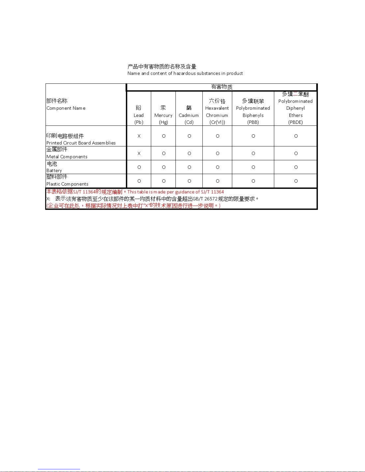
China RoHS Hazardous Material Declaration Table
Electrical Ratings
Backplane Current Load: 800 mA @ 5 VDC; 3 mA @ 24 VDC
Operating Temperature:
0°C to 60°C (32°F to 140°F) - MVI56E-GSC
-25°C to 70°C (-13°F to 158°F) - MVI56E-GSCXT
Storage Temperature: -40°C to 85°C (-40°F to 185°F)
Shock: 30 g operational; 50 g non-operational; Vibration: 5 g from 10 to 150 Hz
Relative Humidity 5% to 95% (without condensation)
All phase conductor sizes must be at least 1.3 mm (squared) and all earth ground conductors must be at least
4mm (squared).
Label Markings
<Ex>
II 3 G
Ex nA IIC T4 Gc
0°C <= Ta <= 60°C
-25°C <= Ta <= 70°C (XT models only)
II – Equipment intended for above ground use (not for use in mines).
3 – Category 3 equipment, investigated for normal operation only.
G – Equipment protected against explosive gasses. <cULus>
E183151
Class I, DIV 2, groups A,B,C,D
T5 for all models
0°C to +60°C
-25°C to +70°C (XT models only)
Page 4

Agency
RoHS
ATEX
CSA
CE
CSA CB Safety
cULus
GOST-R
Lloyds
Agency Approvals and Certifications
Page 5

MVI56E-GSC/GSCXT ♦ CompactLogix or MicroLogix Platform Contents
Enhanced Generic ASCII Serial Communication Module User Manual
Contents
Your Feedback Please ........................................................................................................................ 2
Important Safety Information ............................................................................................................... 2
1 Start Here 9
1.1 What's New? ........................................................................................................... 10
1.2 What's Different? ..................................................................................................... 10
1.3 System Requirements ............................................................................................. 11
1.4 Deployment Checklist .............................................................................................. 12
1.5 Package Contents ................................................................................................... 13
1.6 Setting Jumpers ...................................................................................................... 13
1.7 Installing the Module in the Rack ............................................................................ 14
1.8 Using ProSoft Configuration Builder Software ........................................................ 15
1.8.1 Setting Up the Project ............................................................................................. 16
1.8.2 Connecting Your PC to the Module's Ethernet Port ................................................ 18
1.8.3 Setting Up a Permanent IP Address ....................................................................... 22
1.9 Before You Begin .................................................................................................... 34
1.9.1 About the Optional Add-On Instruction ................................................................... 34
1.10 Creating a New RSLogix 5000 Project .................................................................... 35
1.10.1 Creating the Module ................................................................................................ 36
1.10.2 Importing the Ladder Rung...................................................................................... 38
1.11 Connecting Your PC to the ControlLogix Processor ............................................... 46
1.12 Downloading the Sample Program to the Processor .............................................. 47
2 MVI56E-GSC Configuration 49
2.1 GSC.UTIL.BackplaneFail ........................................................................................ 50
2.2 GSC.CONFIG.PortX ................................................................................................ 51
2.2.1 Port[x].Enabled ........................................................................................................ 51
2.2.2 Port[x].Type ............................................................................................................. 52
2.2.3 Port[x].Baudrate ...................................................................................................... 53
2.2.4 Port[x].Parity ............................................................................................................ 53
2.2.5 Port[x].DataBits ....................................................................................................... 54
2.2.6 Port[x].StopBits ........................................................................................................ 54
2.2.7 Port[x].RTSOn ......................................................................................................... 54
2.2.8 Port[x].RTSOff ......................................................................................................... 54
2.2.9 Port[x].Handshaking ................................................................................................ 54
2.2.10 Port[x].RTermCnt .................................................................................................... 54
2.2.11 Port[x].RTermChar .................................................................................................. 55
2.2.12 Port[x].RPacketLen ................................................................................................. 55
2.2.13 Port[x].RTimeout ..................................................................................................... 55
2.2.14 Port[x].RDelay ......................................................................................................... 55
2.2.15 Port[x].WTermCnt .................................................................................................... 55
2.2.16 Port[x].WTermChar ................................................................................................. 55
2.2.17 Port[x].WPacketLen ................................................................................................. 55
2.2.18 Port[x].WTimeout ..................................................................................................... 56
2.2.19 Port[x].Spare ........................................................................................................... 56
2.2.20 Port[x].WMinDelay ................................................................................................... 56
2.3 Changing parameters during operation ................................................................... 56
ProSoft Technology, Inc. Page 5 of 140
April 24, 2017
Page 6

Contents MVI56E-GSC/GSCXT ♦ CompactLogix or MicroLogix Platform
User Manual Enhanced Generic ASCII Serial Communication Module
3 Diagnostics and Troubleshooting 57
3.1 Reading Status Data from the Module ................................................................... 57
3.2 The Diagnostics Menu ............................................................................................ 58
3.2.1 Using the Diagnostics Menu in ProSoft Configuration Builder ............................... 58
3.3 Monitoring Module Information ............................................................................... 61
3.3.1 Version Menu .......................................................................................................... 61
3.3.2 Config ...................................................................................................................... 62
3.3.3 NIC Status ............................................................................................................... 62
3.4 Monitoring Backplane Information .......................................................................... 62
3.4.1 Backplane Status Menu .......................................................................................... 62
3.5 Data Analyzer ......................................................................................................... 63
3.5.1 Starting the Data Analyzer ...................................................................................... 63
3.5.2 Stopping the Data Analyzer .................................................................................... 65
3.5.3 Data Analyzer Tips ................................................................................................. 66
3.6 Scrolling LED Status Indicators .............................................................................. 68
3.7 Ethernet LED Indicators .......................................................................................... 69
3.8 Non-Scrolling LED Status Indicators ...................................................................... 70
3.9 ControlLogix Processor Not in RUN or REM RUN ................................................. 70
3.10 Clearing a Fault Condition ...................................................................................... 70
3.11 Troubleshooting ...................................................................................................... 71
4 Reference 73
4.1 Product Specifications ............................................................................................ 73
4.1.1 General Specifications ............................................................................................ 73
4.1.2 Functional Specifications ........................................................................................ 74
4.1.3 Hardware Specifications ......................................................................................... 75
4.2 General Concepts ................................................................................................... 76
4.2.1 Backplane Data Transfer ........................................................................................ 76
4.2.2 Data Flow between MVI56E-GSC Module and ControlLogix Processor................ 77
4.2.3 Termination of Received Data ................................................................................ 81
4.3 Normal Data Transfer ............................................................................................. 85
4.3.1 Block Request from the Processor to the Module .................................................. 85
4.3.2 Read Block .............................................................................................................. 86
4.4 Special Function Blocks .......................................................................................... 90
4.4.1 Block 9998: Warm Boot .......................................................................................... 90
4.4.2 Block 9999: Cold Boot ............................................................................................ 90
4.4.3 Configuration Data Transfer Block ......................................................................... 90
4.5 Using the Sample Add-On Instruction .................................................................... 92
4.5.1 Input/Output (I/O) Configuration and Module Properties ........................................ 92
4.5.2 User-Defined Data Types ....................................................................................... 93
4.5.3 Controller Tags ..................................................................................................... 101
4.5.4 Add-On-Defined Data Types ................................................................................ 107
4.6 Using the Optional Add-On Instruction ................................................................. 112
4.6.1 Before You Begin .................................................................................................. 112
4.6.2 Overview ............................................................................................................... 112
4.6.3 Importing the Optional Add-On Instruction Rung .................................................. 113
4.6.4 Reading Ethernet Settings from the Module ......................................................... 117
4.6.5 Writing the Ethernet Settings to the Module ......................................................... 119
4.6.6 Reading the Clock Value from the Module ........................................................... 120
4.6.7 Writing the Clock Value to the Module ................................................................. 121
4.7 Using the Sample Program - RSLogix 5000 Version 15 and earlier .................... 122
Page 6 of 140 ProSoft Technology, Inc.
April 24, 2017
Page 7

MVI56E-GSC/GSCXT ♦ CompactLogix or MicroLogix Platform Contents
Enhanced Generic ASCII Serial Communication Module User Manual
4.7.1 Opening the Sample Program in RSLogix ............................................................ 122
4.7.2 Choosing the Controller Type ............................................................................... 125
4.7.3 Select the Slot Number for the Module ................................................................. 126
4.7.4 Downloading the Sample Program to the Processor ............................................ 127
4.8 Adding the Sample Ladder to an Existing Application .......................................... 128
4.9 Error/Configuration Word ...................................................................................... 130
4.10 Cable Connections ................................................................................................ 130
4.10.1 Ethernet Cable Specifications ............................................................................... 131
4.10.2 Ethernet Performance ........................................................................................... 131
4.10.3 Ethernet Cable Configuration ................................................................................ 132
4.10.4 RS-232 Application Port(s) ................................................................................... 132
4.10.5 RS-422 .................................................................................................................. 135
4.10.6 RS-485 Application Port(s) .................................................................................... 135
4.10.7 DB9 to RJ45 Adaptor (Cable 14) .......................................................................... 136
5 Support, Service & Warranty 137
5.1 Contacting Technical Support ............................................................................... 137
5.2 Warranty Information ............................................................................................. 138
Index 139
ProSoft Technology, Inc. Page 7 of 140
April 24, 2017
Page 8

MVI56E-GSC/GSCXT ♦ CompactLogix or MicroLogix Platform Start Here
Enhanced Generic ASCII Serial Communication Module User Manual
ProSoft Technology, Inc. Page 8 of 140
April 24, 2017
Page 9

MVI56E-GSC/GSCXT ♦ CompactLogix or MicroLogix Platform Start Here
In This Chapter
What's New? ........................................................................................... 9
What's Different? ................................................................................... 10
System Requirements ........................................................................... 11
Deployment Checklist ............................................................................ 12
Package Contents ................................................................................. 13
Setting Jumpers .................................................................................... 13
Installing the Module in the Rack ........................................................... 14
Using ProSoft Configuration Builder Software ....................................... 15
Before You Begin .................................................................................. 34
Creating a New RSLogix 5000 Project .................................................. 35
Connecting Your PC to the ControlLogix Processor .............................. 46
Downloading the Sample Program to the Processor ............................. 47
Enhanced Generic ASCII Serial Communication Module User Manual
1 Start Here
To get the most benefit from this User Manual, you should be familiar with:
Rockwell Automation® RSLogix™ software: launch the program, configure
ladder logic, and transfer the ladder logic to the processor
Microsoft Windows®: install and launch programs, execute menu
commands, navigate dialog boxes, and enter data
Hardware installation and wiring: install the module, and safely connect
generic ASCII serial and ControlLogix devices to a power source and to the
MVI56E-GSC module’s application port(s)
Important: All references to the module pertain to both the MVI56E-GSC and MVI56E-GSCXT
unless stated otherwise.
ProSoft Technology, Inc. Page 9 of 140
April 24, 2017
Page 10

Start Here MVI56E-GSC/GSCXT ♦ CompactLogix or MicroLogix Platform
User Manual Enhanced Generic ASCII Serial Communication Module
1.1 What's New?
MVI56E products are backward compatible with existing MVI56 products,
ladder logic, and module configuration files already in use. Easily swap and
upgrade to benefit from an array of new features designed to improve
interoperability and enhance ease of use.
ProSoft Configuration Builder (PCB): Microsoft Windows®-based utility
software for diagnostics. Connect through the module's Ethernet port or use
CIPconnect® to access troubleshooting features and functions.
ProSoft Discovery Service (PDS): New Windows-based utility software to
find and display a list of MVI56E modules on the network and to temporarily
change a module's IP address to be able to connect with a module's web
page.
CIPconnect-enabled: Allows PC-to-module diagnostics from the Ethernet
network through a ControlLogix® 1756-ENxT EtherNet/IP™ module.
Personality Card: An industrial-grade compact flash memory card storing
the module’s Ethernet settings, allowing quick and easy replacement.
LED Scrolling Diagnostic Display: 4-character, alphanumeric display,
providing English messages for status and alarm data, and for processor and
network communication status.
1.2 What's Different?
The MVI56E-GSC Generic ASCII Serial Communication module is configured in
RSLogix™ 5000 software using the sample ladder or Add-On Instruction (AOI). It
also uses ProSoft Discovery Service (PDS), ProSoft Configuration Builder (PCB),
as well as all required product documentation.
PDS is the software utility used to allow your PC to connect to the module to
set a temporary Ethernet IP address. Then you can connect to the module's
web page to retrieve or change the module's firmware though an Ethernet
link.
PCB is the software used to provide access to the module's diagnostic
menus and application serial port communication data analyzer features.
Page 10 of 140 ProSoft Technology, Inc.
April 24, 2017
Page 11
MVI56E-GSC/GSCXT ♦ CompactLogix or MicroLogix Platform Start Here
Enhanced Generic ASCII Serial Communication Module User Manual
1.3 System Requirements
The MVI56E-GSC module requires the following minimum hardware and
software components:
Rockwell Automation ControlLogix® processor (firmware version 10 or higher)
with compatible limited voltage power supply and one free slot in the rack for
the MVI56E-GSC module. The module requires 800mA of available 5 VDC
and 3 mA of available 24 VDC power.
Rockwell Automation RSLogix 5000 programming software
o Version 16 or higher required for Add-On Instruction
o Version 15 or lower must use Sample Ladder, available from
www.prosoft-technology.com
Rockwell Automation RSLinx® communication software version 2.51 or higher
ProSoft Configuration Builder (PCB) (included)
Pentium® II 450 MHz minimum. Pentium III 733 MHz (or better)
recommended
Supported operating systems:
o Microsoft Windows
o Microsoft Windows XP Professional with Service Pack 1 or 2
o Microsoft Windows 7 Professional (32-or 64-bit)
o Microsoft Windows 2000 Professional with Service Pack 1, 2, or 3
o Microsoft Windows Server 2003
128 Mbytes of RAM minimum, 256 Mbytes of RAM recommended
100 Mbytes of free hard disk space (or more based on application
requirements)
256-color VGA graphics adapter, 800 x 600 minimum resolution (True Color
1024 768 recommended)
®
Vista
Note: The Hardware and Operating System requirements in this list are the minimum
recommended to install and run software provided by ProSoft Technology®. Other third party
applications may have different minimum requirements. Refer to the documentation for any third
party applications for system requirements.
Note: You can install the module in a local or remote rack. For remote rack installation, the module
requires EtherNet/IP or ControlNet communication with the processor.
ProSoft Technology, Inc. Page 11 of 140
April 24, 2017
Page 12

Start Here MVI56E-GSC/GSCXT ♦ CompactLogix or MicroLogix Platform
User Manual Enhanced Generic ASCII Serial Communication Module
1.4 Deployment Checklist
Before you begin configuring the module, consider the following questions. Your
answers will help you determine the scope of your project, and the configuration
requirements for a successful deployment.
1 ____________ Are you creating a new application or integrating the module
into an existing application?
Most applications can use the Sample Add-On Instruction or Sample Ladder
Logic without any edits to the Sample Program.
2 ____________ Which slot number in the chassis will the MVI56E-GSC
module occupy?
For communication to occur, you must enter the correct slot number in the
sample program.
3 ____________ Are RSLogix 5000 and RSLinx installed?
RSLogix and RSLinx are required to communicate to the ControlLogix
processor (1756-L1, L5x, L6x). Sample Ladder programs are available for
different versions of RSLogix 5000.
4 ____________ How many words of data do you need to transfer in your
application (from ControlLogix to Module / to ControlLogix from Module)?
The MVI56E-GSC module can transfer a maximum of 5000 (16-bit) registers
to and from the ControlLogix processor. The Sample Ladder transfers 600
words to the ControlLogix processor (into the Read Data array), and obtains
600 words from the ControlLogix processor (from the Write Data array)
5 Serial Communication Parameters for the network:
____________ Baud rate?
____________ Data bits?
____________ Parity?
____________ Stop bits?
6 ____________ Wiring type to use (RS232, 422 or 485). Configured by
jumper settings.
Required for proper implementation of the module.
Note: If you are installing your module into a new system, and plan to use our Sample Ladder
Logic, refer to the printed Quick Start Guide in the module package for simple installation
procedures.
For version 16 or newer of RSLogix 5000, refer to Upload the Add-On Instruction from the
Module.
For EXISTING system installations, refer to Using the Sample Program - RSLogix 5000
Version 15 and earlier (page 122).
Note: Most applications can use the Sample Ladder Logic without modifying the sample program.
Page 12 of 140 ProSoft Technology, Inc.
April 24, 2017
Page 13
MVI56E-GSC/GSCXT ♦ CompactLogix or MicroLogix Platform Start Here
Qty.
Part Name
Part Number
Part Description
1
MVI56E-GSC Module
MVI56E-GSC
Enhanced Generic ASCII Serial
Communication Module
1
Cable
RL-CBL025
5 foot Ethernet Straight-Through Cable
2
Cable
Cable #14, RJ45 to
DB9 Male Adapter
cable
For DB9 Connection to Module’s
Application Serial Port
2
Adapter
1454-9F
Two Adapters, DB9 Female to Screw
Terminal. For RS422 or RS485
Connections to Port 1 and 2 of the Module
Enhanced Generic ASCII Serial Communication Module User Manual
1.5 Package Contents
The following components are included with your MVI56E-GSC module, and are
all required for installation and configuration.
Important: Before beginning the installation, please verify that all of the following items are
present.
If any of these components are missing, please contact ProSoft Technology
Support for replacement parts.
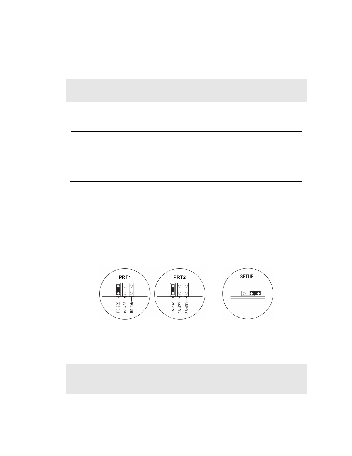
1.6 Setting Jumpers
There are three jumpers located at the bottom of the module. The first two
jumpers (P1 and P2) set the serial communication mode: RS-232, RS-422 or RS-
485.
The following illustration shows the MVI56E-GSC jumper configuration, with the
Setup Jumper OFF.
The Setup Jumper acts as "write protection" for the module’s firmware. In "write
protected" mode, the Setup pins are not connected, and the module’s firmware
cannot be overwritten. The module is shipped with the Setup jumper OFF. If you
need to update the firmware, apply the Setup jumper to both pins.
Note: If you are installing the module in a remote rack, you may prefer to leave the Setup pins
jumpered. That way, you can update the module’s firmware without requiring physical access to
the module.
ProSoft Technology, Inc. Page 13 of 140
April 24, 2017
Page 14
Start Here MVI56E-GSC/GSCXT ♦ CompactLogix or MicroLogix Platform
User Manual Enhanced Generic ASCII Serial Communication Module
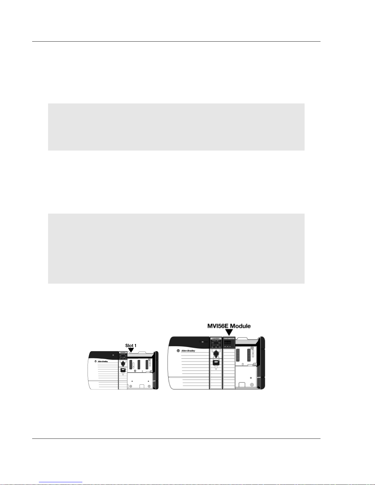
1.7 Installing the Module in the Rack
Make sure your ControlLogix processor and power supply are installed and
configured, before installing the MVI56E-GSC module. Refer to your Rockwell
Automation product documentation for installation instructions.
Warning: You must follow all safety instructions when installing this or any other electronic
devices. Failure to follow safety procedures could result in damage to hardware or data, or even
serious injury or death to personnel. Refer to the documentation for each device you plan to
connect to verify that suitable safety procedures are in place before installing or servicing the
device.
After you have checked the placement of the jumpers, insert the MVI56E-GSC
into the ControlLogix chassis. Use the same technique recommended by
Rockwell Automation to remove and install ControlLogix modules.
You can install or remove ControlLogix system components while chassis power
is applied and the system is operating. However, please note the following
warning.
Warning: When you insert or remove the module while backplane power is on, an electrical arc
can occur. An electrical arc can cause personal injury or property damage by sending an
erroneous signal to the system’s actuators. This can cause unintended machine motion or loss of
process control. Electrical arcs may also cause an explosion when they happen in a hazardous
environment. Verify that power is removed or the area is non-hazardous before proceeding.
Repeated electrical arcing causes excessive wear to contacts on both the module and its mating
connector. Worn contacts may create electrical resistance that can affect module operation.
1 Align the module with the top and bottom guides, and then slide it into the
rack until the module is firmly against the backplane connector.
2 With a firm, steady push, snap the module into place.
3 Check that the holding clips on the top and bottom of the module are securely
in the locking holes of the rack.
Page 14 of 140 ProSoft Technology, Inc.
April 24, 2017
Page 15

MVI56E-GSC/GSCXT ♦ CompactLogix or MicroLogix Platform Start Here
Enhanced Generic ASCII Serial Communication Module User Manual
4 Make a note of the slot location. You must identify the slot in which the
module is installed in order for the sample program to work correctly. Slot
numbers are identified on the green circuit board (backplane) of the
ControlLogix rack.
5 Turn power ON.
Note: If you insert the module improperly, the system may stop working or may behave
unpredictably.
Note: When using the MVI56E-GSCXT, you must use the 1756-A5XT or 1756-A7LXT chassis to
uphold the XT specifications. In these chassis, modules are spaced further apart than in standard
ControlLogix chassis. Blank spacers are inserted between active modules.
1.8 Using ProSoft Configuration Builder Software
ProSoft Configuration Builder (PCB) provides a quick and easy way to manage
module configuration files customized to meet your application needs. PCB is not
only a powerful solution for new configuration files, but also allows you to import
information from previously installed (known working) configurations to new
projects.
The ProSoft Discovery Service (PDS) is available as a stand-alone application,
or as part of ProSoft Configuration Builder. ProSoft Discovery Service shows you
all the MVI56E modules available on your local area network.
Note: The MVI56E-GSC module receives its protocol and backplane configuration information from
the Ladder Logic. Use ProSoft Configuration Builder to configure the module’s Ethernet settings.
ProSoft Technology, Inc. Page 15 of 140
April 24, 2017
Page 16
Start Here MVI56E-GSC/GSCXT ♦ CompactLogix or MicroLogix Platform
User Manual Enhanced Generic ASCII Serial Communication Module
1.8.1 Setting Up the Project
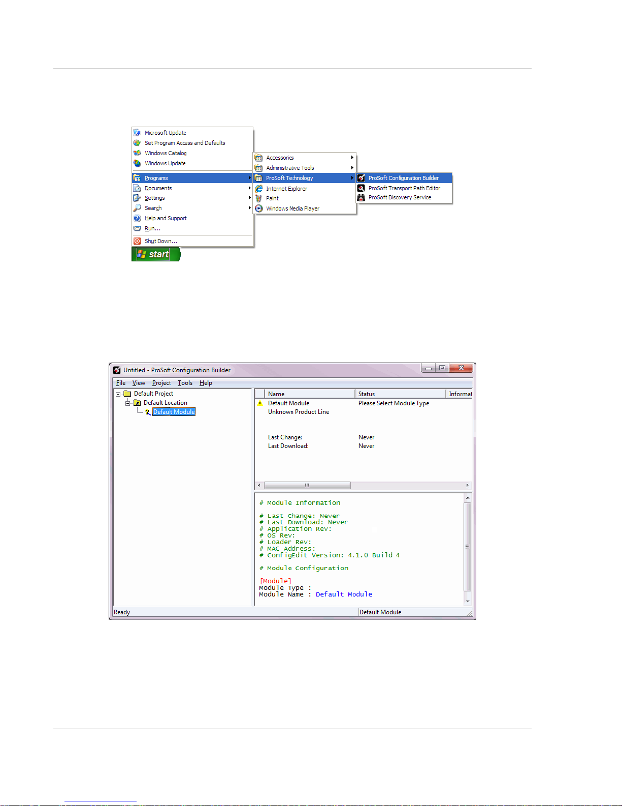
To begin, start PROSOFT CONFIGURATION BUILDER (PCB).
If you have used other Windows configuration tools before, you will find the
screen layout familiar. PCB’s window consists of a tree view on the left, and an
information pane and a configuration pane on the right side of the window. When
you first start PCB, the tree view consists of folders for Default Project and
Default Location, with a Default Module in the Default Location folder. The
following illustration shows the PCB window with a new project.
Page 16 of 140 ProSoft Technology, Inc.
April 24, 2017
Page 17
MVI56E-GSC/GSCXT ♦ CompactLogix or MicroLogix Platform Start Here
Enhanced Generic ASCII Serial Communication Module User Manual
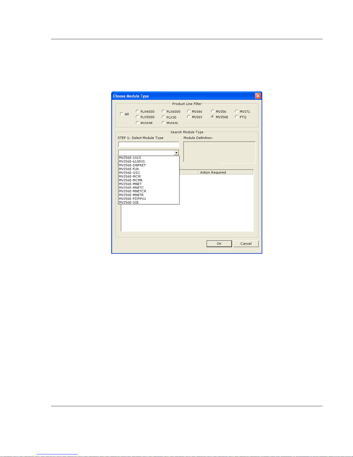
Your first task is to add the MVI56E-GSC module to the project.
1 Use the mouse to select DEFAULT MODULE in the tree view, and then click the
right mouse button to open a shortcut menu.
2 On the shortcut menu, select CHOOSE MODULE TYPE. This action opens the
Choose Module Type dialog box.
3 In the Product Line Filter area of the dialog box, select MVI56E. In the Select
Module Type dropdown list, select MVI56E-GSC, and then click OK to save
your settings and return to the ProSoft Configuration Builder window.
ProSoft Technology, Inc. Page 17 of 140
April 24, 2017
Page 18
Start Here MVI56E-GSC/GSCXT ♦ CompactLogix or MicroLogix Platform
User Manual Enhanced Generic ASCII Serial Communication Module
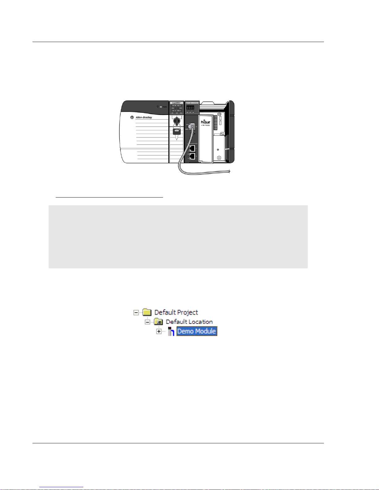
1.8.2 Connecting Your PC to the Module's Ethernet Port
With the module securely mounted, connect one end of the Ethernet cable to the
CONFIG (E1) Port, and the other end to an Ethernet hub or switch accessible from
the same network as your PC. Or, you can connect directly from the Ethernet
Port on your PC to the CONFIG (E1) Port on the module.
Setting Up a Temporary IP Address
Important: ProSoft Configuration Builder locates MVI56E-GSC modules through UDP broadcast
messages. These messages may be blocked by routers or layer 3 switches. In that case, ProSoft
Discovery Service will be unable to locate the modules.
To use ProSoft Configuration Builder, arrange the Ethernet connection so that there is no router/
layer 3 switch between the computer and the module OR reconfigure the router/ layer 3 switch to
allow routing of the UDP broadcast messages.
1 In the tree view in ProSoft Configuration Builder, select the MVI56E-GSC
module.
Page 18 of 140 ProSoft Technology, Inc.
April 24, 2017
Page 19
MVI56E-GSC/GSCXT ♦ CompactLogix or MicroLogix Platform Start Here
Enhanced Generic ASCII Serial Communication Module User Manual
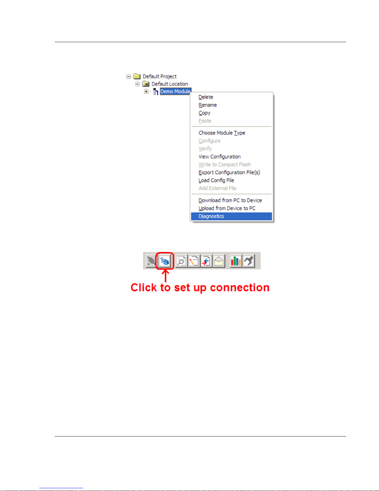
2 Click the right mouse button to open a shortcut menu. On the shortcut menu,
choose DIAGNOSTICS.
3 In the Diagnostics window, click the SET UP CONNECTION button.
ProSoft Technology, Inc. Page 19 of 140
April 24, 2017
Page 20
Start Here MVI56E-GSC/GSCXT ♦ CompactLogix or MicroLogix Platform
User Manual Enhanced Generic ASCII Serial Communication Module
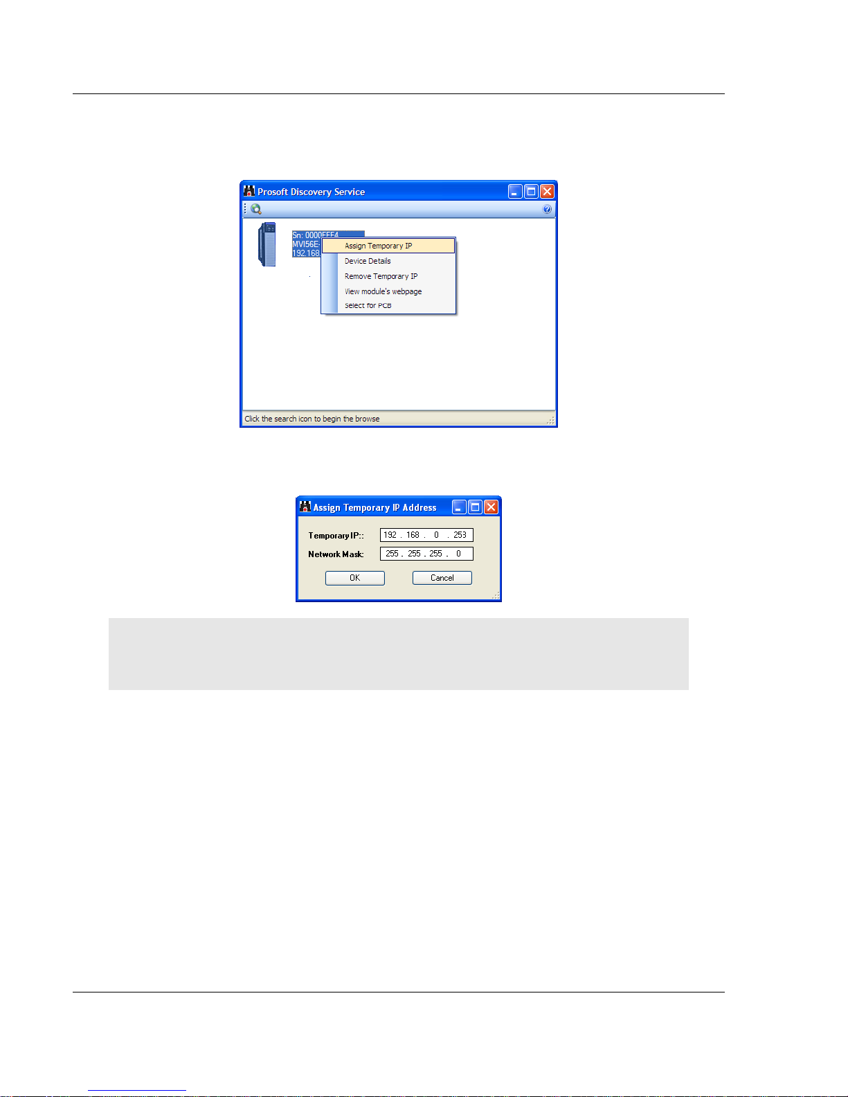
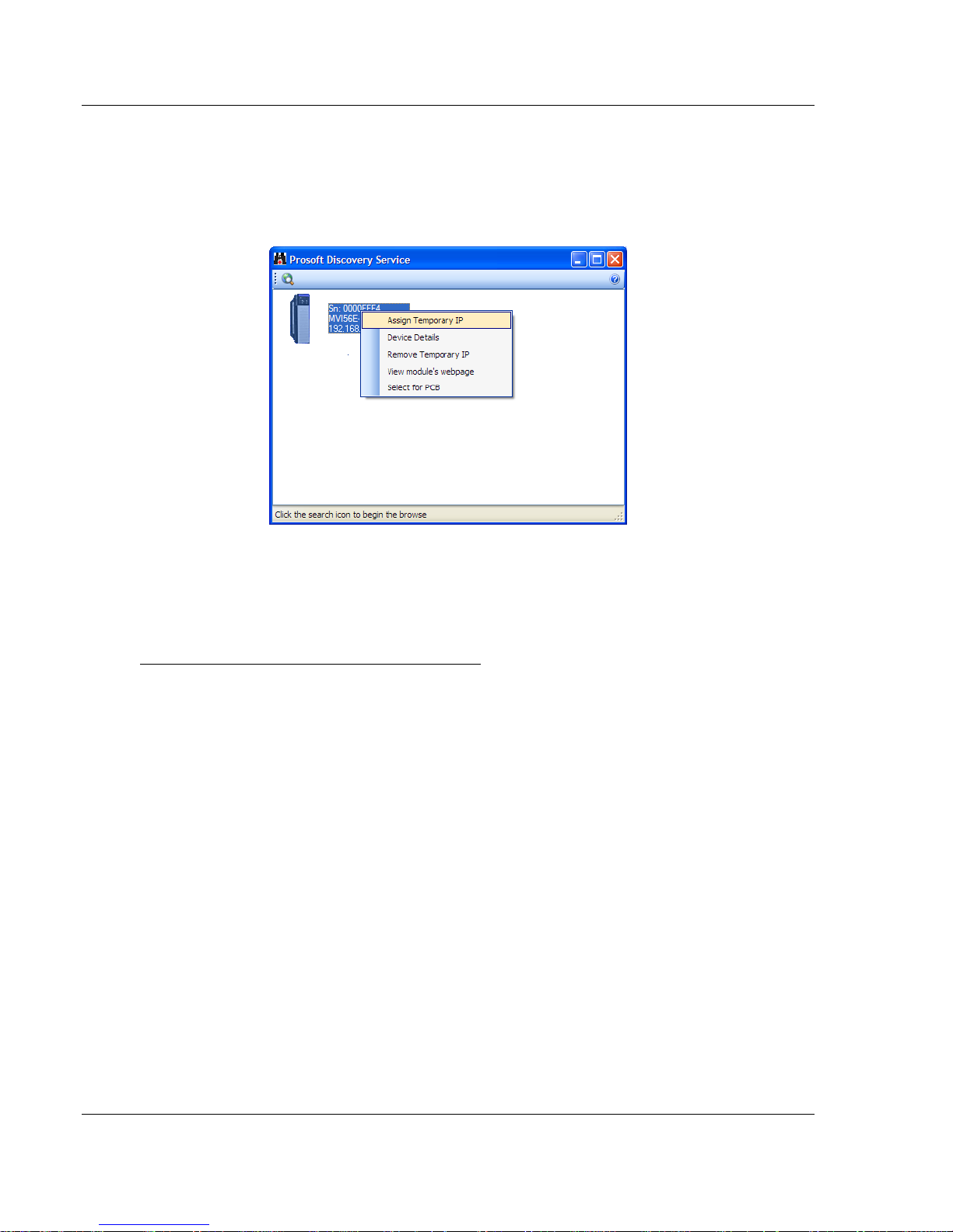
4 In the Connection Setup dialog box, click the BROWSE DEVICE(S) button to
open the ProSoft Discovery Service. Select the module, then right-click and
choose ASSIGN TEMPORARY IP.
5 The module’s default IP address is usually 192.168.0.250. Choose an unused
IP within your subnet, and then click OK.
Important: The temporary IP address is only valid until the next time the module is initialized. For
information on how to set the module’s permanent IP address, see Setting Up a Permanent IP
Address (page 22).
Page 20 of 140 ProSoft Technology, Inc.
April 24, 2017
Page 21
MVI56E-GSC/GSCXT ♦ CompactLogix or MicroLogix Platform Start Here
Enhanced Generic ASCII Serial Communication Module User Manual
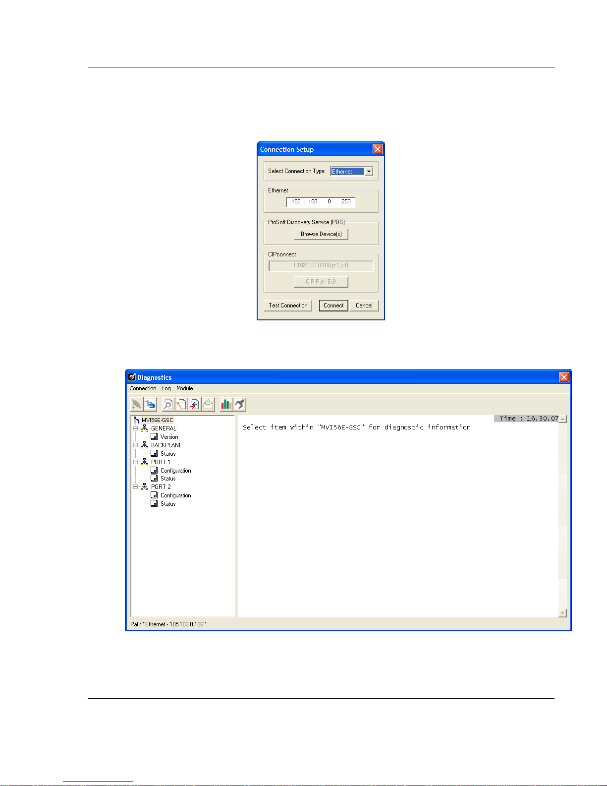
6 Close the ProSoft Discovery Service window. Enter the temporary IP in the
Ethernet address field of the Connection Setup dialog box, then click the
TEST CONNECTION button to verify that the module is accessible with the
current settings.
7 If the Test Connection is successful, click CONNECT. The Diagnostics menu
displays in the Diagnostics window.
ProSoft Technology, Inc. Page 21 of 140
April 24, 2017
Page 22
Start Here MVI56E-GSC/GSCXT ♦ CompactLogix or MicroLogix Platform
User Manual Enhanced Generic ASCII Serial Communication Module
1.8.3 Setting Up a Permanent IP Address
Note: For alternative methods of connecting to the module with your PC, refer to Using
CIPconnect® to Connect to the Module (page 24) or Using RSWho to Connect to the Module (page
33).
These steps show you how to set a permanent IP address on the module. This
example assumes module’s default IP address is 192.168.0.250.
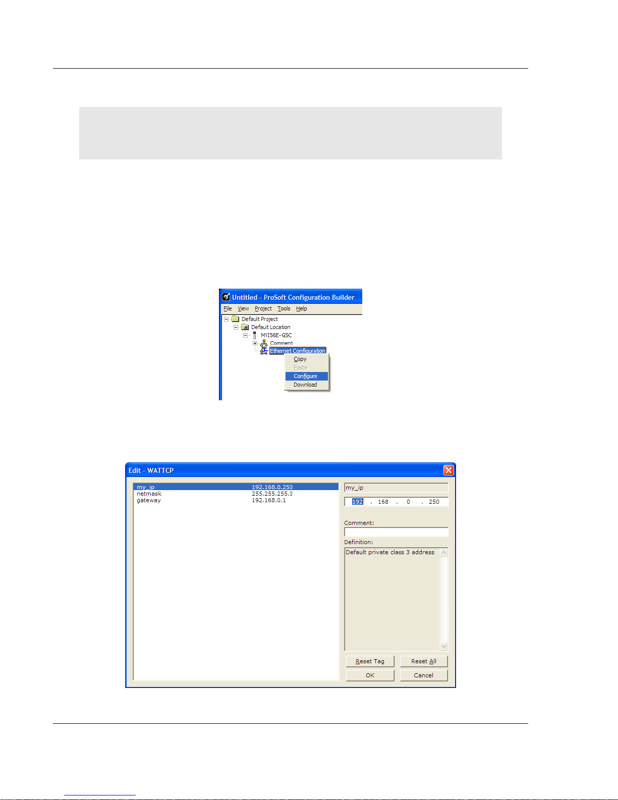
1 Start ProSoft Configuration Builder.
2 Select the MVI56E-GSC icon, and then click the [+] symbol to expand the
MVI56E-GSC tree.
3 Select ETHERNET CONFIGURATION, and then click the right mouse button to
open a shortcut menu.
4 On the shortcut menu, select CONFIGURE.
This action opens the Edit-WATTCP dialog box. Use this dialog box to enter
the MVI56E-GSC module’s permanent IP Address (MY_IP), SUBNET MASK
(NETMASK) and DEFAULT GATEWAY (GATEWAY).
Page 22 of 140 ProSoft Technology, Inc.
April 24, 2017
Page 23
MVI56E-GSC/GSCXT ♦ CompactLogix or MicroLogix Platform Start Here
Enhanced Generic ASCII Serial Communication Module User Manual
5 Click OK to save the updated Ethernet configuration.
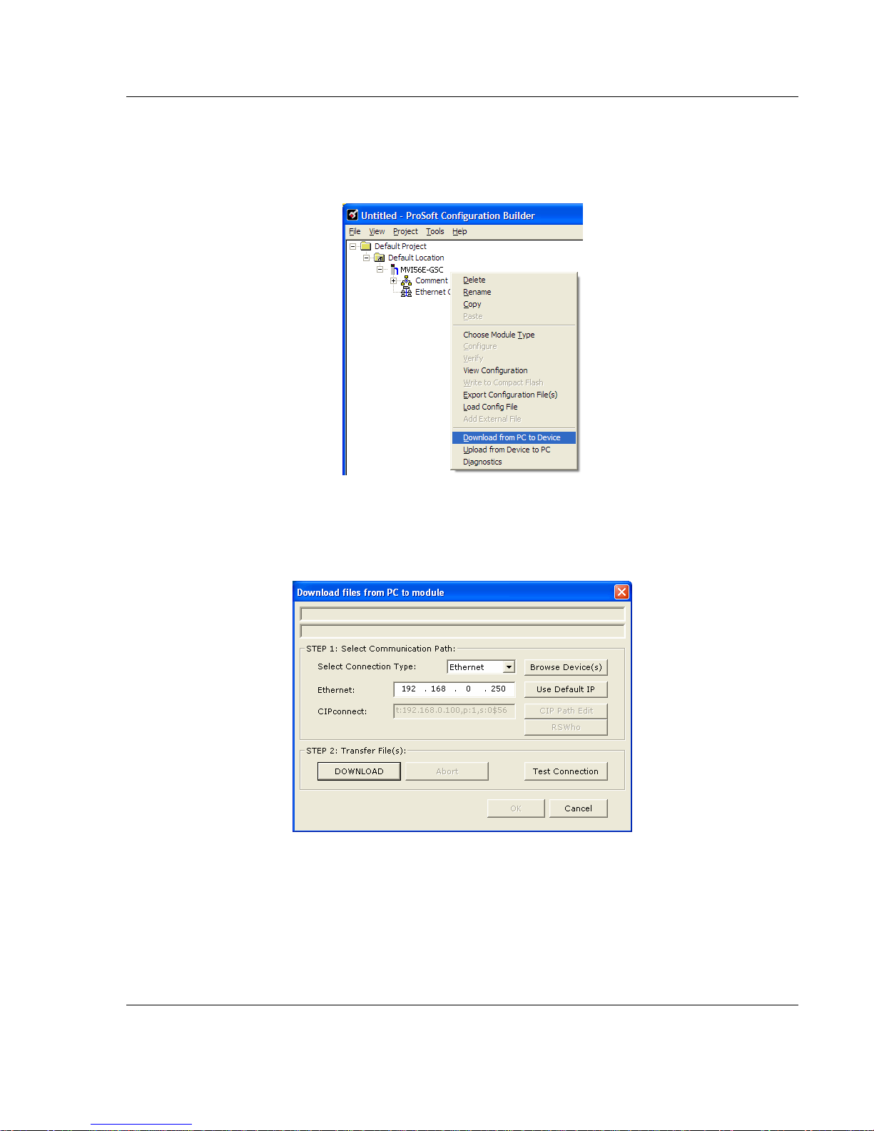
6 Next, select the MVI56E-GSC icon, and then click the right mouse button to
open a shortcut menu. On the shortcut menu, choose DOWNLOAD FROM PC
TO DEVICE.
This action opens the DOWNLOAD dialog box. Notice that the Ethernet
address field contains the temporary IP address you assigned previously.
ProSoft Configuration Builder will use this temporary IP address to connect to
the module.
Click TEST CONNECTION to verify that the temporary IP address is correct.
7 If the connection succeeds, click DOWNLOAD to transfer the Ethernet
configuration to the module.
ProSoft Technology, Inc. Page 23 of 140
April 24, 2017
Page 24
Start Here MVI56E-GSC/GSCXT ♦ CompactLogix or MicroLogix Platform
User Manual Enhanced Generic ASCII Serial Communication Module
If the Test Connection procedure fails, you will see an error message. To correct
the error, follow these steps.
1 Click OK to dismiss the error message.
2 On the DOWNLOAD dialog box, click BROWSE DEVICES to open PROSOFT
DISCOVERY SERVICE.
3 Select the module, and then click the right mouse button to open a shortcut
menu. On the shortcut menu, choose SELECT FOR PCB.
4 Close Prosoft Discovery Service.
5 Click DOWNLOAD to transfer the Ethernet configuration to the module.
Using CIPconnect® to Connect to the Module
You can use CIPconnect® to connect a PC to the ProSoft Technology MVI56EGSC module over Ethernet using Rockwell Automation’s 1756-ENBT
EtherNet/IP® module. This allows you to configure the MVI56E-GSC network
settings and view module diagnostics from a PC. RSLinx is not required when
you use CIPconnect. All you need are:
The IP addresses and slot numbers of any 1756-ENBT modules in the path
The slot number of the MVI56E-GSC in the destination ControlLogix chassis
(the last ENBTx and chassis in the path).
Page 24 of 140 ProSoft Technology, Inc.
April 24, 2017
Page 25
MVI56E-GSC/GSCXT ♦ CompactLogix or MicroLogix Platform Start Here
Enhanced Generic ASCII Serial Communication Module User Manual
To use CIPconnect, follow these steps.
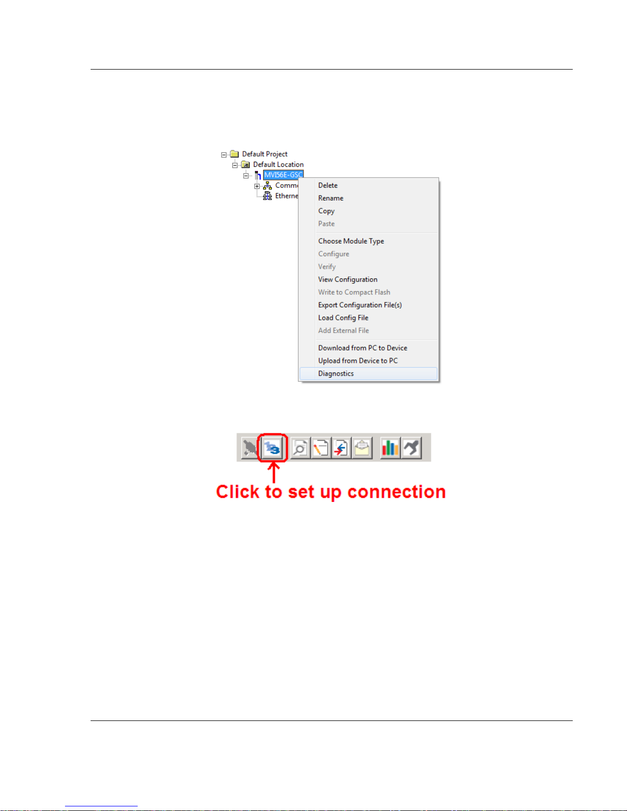
1 In the tree view in ProSoft Configuration Builder, right-click the MVI56E-GSC
icon to open a shortcut menu.
2 On the shortcut menu, choose DIAGNOSTICS.
3 In the Diagnostics window, click the SET UP CONNECTION button.
ProSoft Technology, Inc. Page 25 of 140
April 24, 2017
Page 26
Start Here MVI56E-GSC/GSCXT ♦ CompactLogix or MicroLogix Platform
User Manual Enhanced Generic ASCII Serial Communication Module
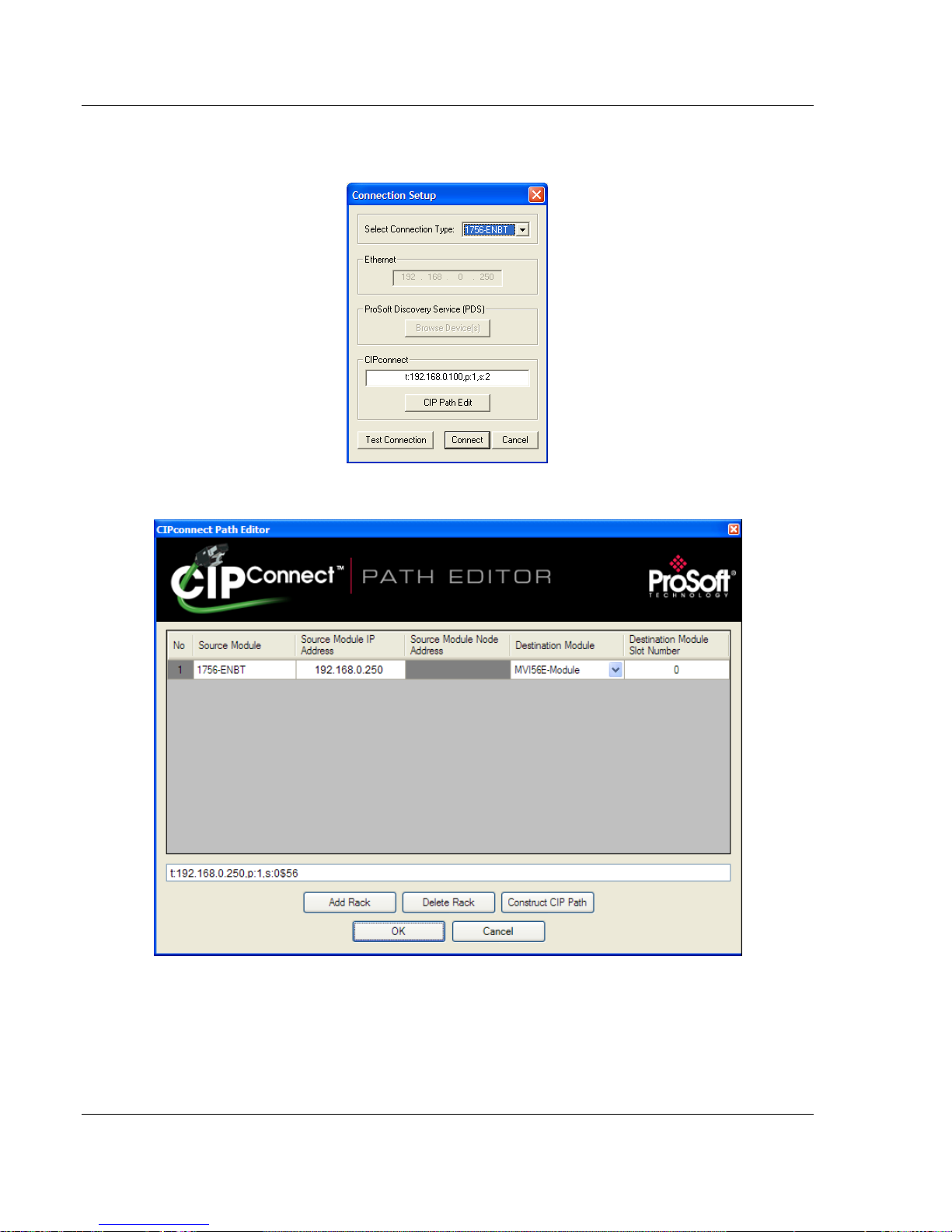
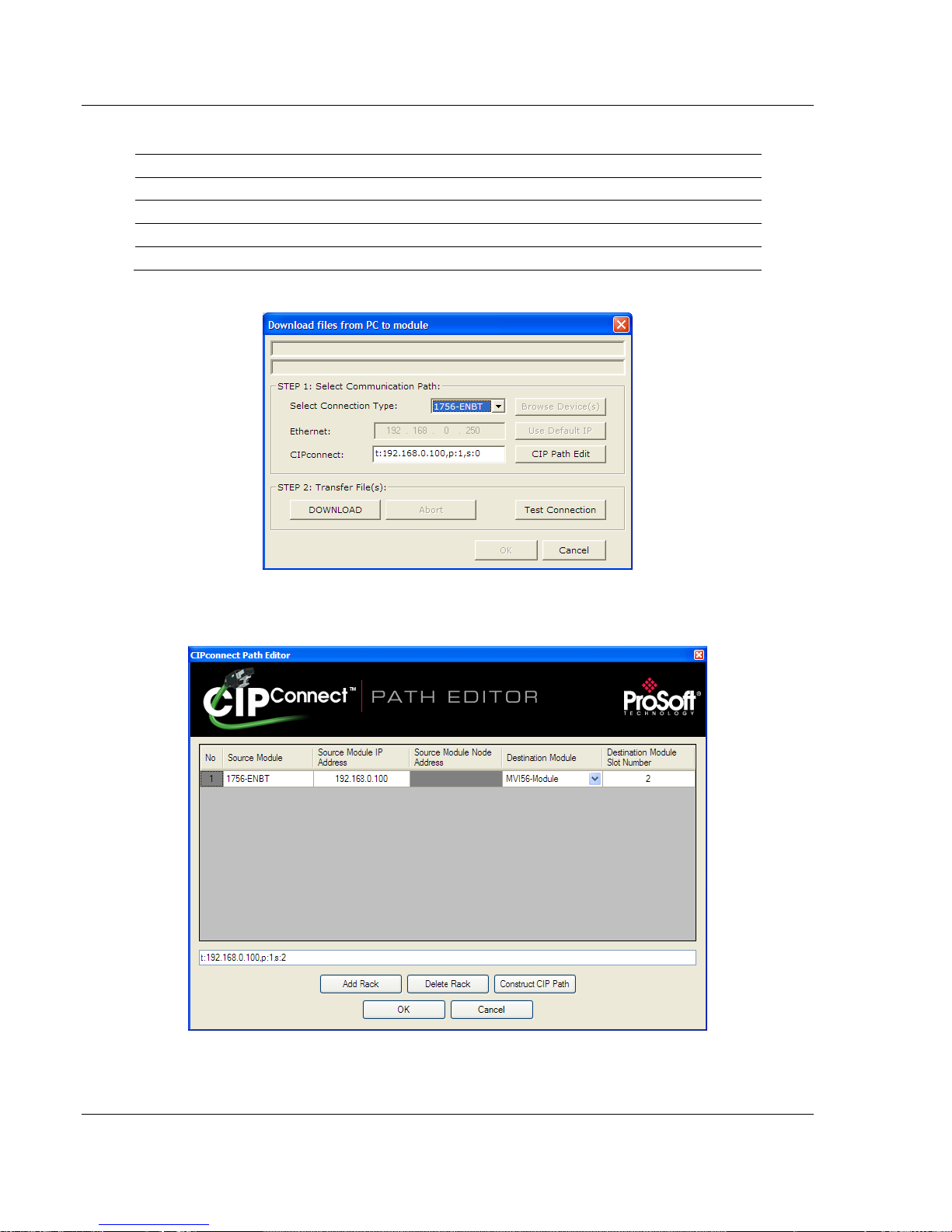
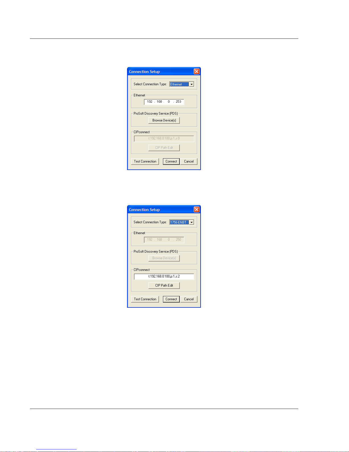
4 In the Select Connection Type dropdown list, choose 1756-ENBT. The
default path appears in the text box, as shown in the following illustration.
5 Click CIP PATH EDIT to open the CIPconnect Path Editor dialog box.
The CIPconnect Path Editor allows you to define the path between the PC and
the MVI56E-GSC module. The first connection from the PC is always a 1756ENBT (Ethernet/IP) module.
Each row corresponds to a physical rack in the CIP path.
Page 26 of 140 ProSoft Technology, Inc.
April 24, 2017
Page 27
MVI56E-GSC/GSCXT ♦ CompactLogix or MicroLogix Platform Start Here
Parameter
Description
Source Module
Source module type. This field is automatically selected
depending on the destination module of the last rack (1756CNB or 1756-ENBT).
Source Module IP Address
IP address of the source module (only applicable for 1756ENBT)
Source Module Node Address
Node address of the source module (only applicable for 1756CNB)
Destination Module
Select the destination module associated to the source module
in the rack. The connection between the source and destination
modules is performed through the backplane.
Destination Module Slot Number
The slot number where the destination MVI56E module is
located.
Ethernet
Rack 1
MVI56E Module 1756-ENBT
0 1 2
3
Enhanced Generic ASCII Serial Communication Module User Manual
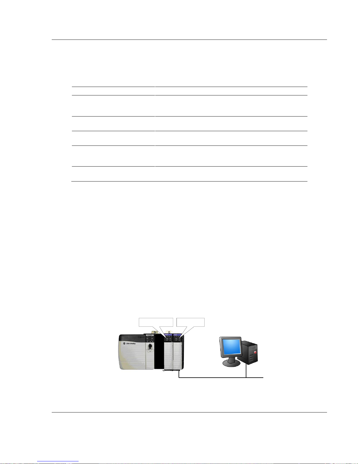
If the MVI56E-GSC module is located in the same rack as the first 1756-
ENBT module, select RACK NO. 1 and configure the associated parameters.
If the MVI56E-GSC is available in a remote rack (accessible through
ControlNet or Ethernet/IP), include all racks (by using the ADD RACK button).
To use the CIPconnect Path Editor, follow these steps.
1 Configure the path between the 1756-ENBT connected to your PC and the
MVI56E-GSC module.
o If the module is located in a remote rack, add more racks to configure the
full path.
o The path can only contain ControlNet or Ethernet/IP networks.
o The maximum number of supported racks is six.
2 Click CONSTRUCT CIP PATH to build the path in text format
3 Click OK to confirm the configured path.
The following examples should provide a better understanding on how to set up
the path for your network.
Example 1: Local Rack Application
For this example the MVI56E-GSC module is located in the same rack as the
1756-ENBT that is connected to the PC.
ProSoft Technology, Inc. Page 27 of 140
April 24, 2017
Page 28
Start Here MVI56E-GSC/GSCXT ♦ CompactLogix or MicroLogix Platform
Slot
Module
Network Address
0
ControlLogix Processor
- 1 Any
-
2
MVI56E-GSC
- 3 1756-ENBT
IP=192.168.0.100
User Manual Enhanced Generic ASCII Serial Communication Module
Rack 1
1 In the Download window, click CIP PATH EDIT.
2 Configure the path as shown in the following illustration, and click
CONSTRUCT CIP PATH to build the path in text format.
Click OK to close the CIP PATH EDITOR and return to the Download dialog
box.
Page 28 of 140 ProSoft Technology, Inc.
April 24, 2017
Page 29
MVI56E-GSC/GSCXT ♦ CompactLogix or MicroLogix Platform Start Here
Enhanced Generic ASCII Serial Communication Module User Manual
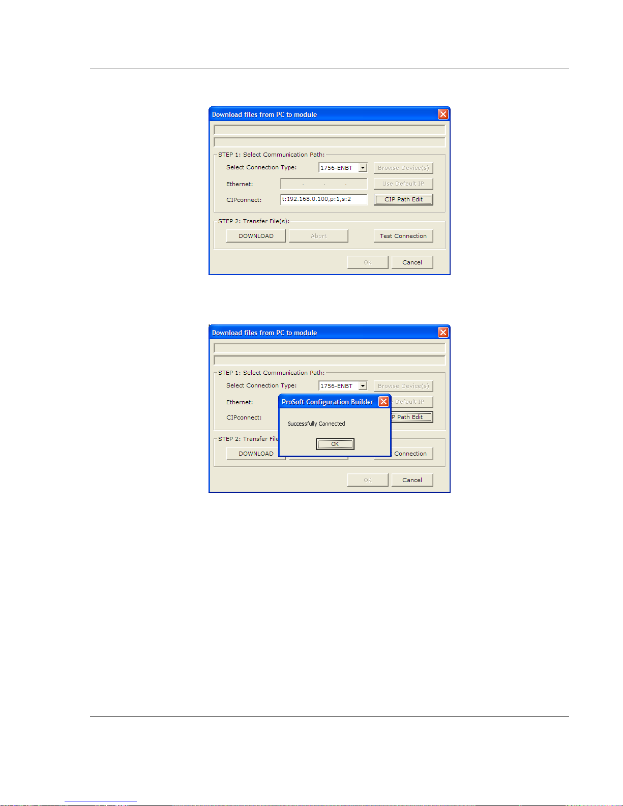
3 Check the new path in the download text box.
4 Click TEST CONNECTION to verify that the physical path is available. The
following message should be displayed upon success.
5 Click OK to close the Test Connection pop-up. You are now ready to use
CIPconnect for downloading changes to the module's Ethernet configuration
settings. You may also use this connection to access module diagnostics
screens and menus. For more information, see the chapter on Diagnostics
and Troubleshooting. For more information, see the chapter on Diagnostics
and Troubleshooting (page 57).
ProSoft Technology, Inc. Page 29 of 140
April 24, 2017
Page 30

Start Here MVI56E-GSC/GSCXT ♦ CompactLogix or MicroLogix Platform
Ethernet
Rack 1
0 1 2 3
ControlNet
0
1 2 3 4 5
6
Rack 2
1756-ENBT
1756-CNB
1756-CNB
MVI56E Module
Slot
Module
Network Address
0
ControlLogix Processor
-
1
1756-CNB
Node = 1
2
1756-ENBT
IP=192.168.0.100
3
Any
-
Slot
Module
Network Address
0
Any
-
1
Any - 2
Any
-
3
Any - 4
Any
-
5
1756-CNB
Node = 2
6
MVI56E-GSC
-
User Manual Enhanced Generic ASCII Serial Communication Module
Example 2: Remote Rack Application - CIPconnect No Download
For this example, the MVI56E-GSC module is located in a remote rack
accessible through ControlNet, as shown in the following illustration.
Rack 1
Rack 2
Page 30 of 140 ProSoft Technology, Inc.
April 24, 2017
Page 31

MVI56E-GSC/GSCXT ♦ CompactLogix or MicroLogix Platform Start Here
Enhanced Generic ASCII Serial Communication Module User Manual
1 In the Download window, click CIP PATH EDIT.
2 Configure the path as shown in the following illustration for this example and
click CONSTRUCT CIP PATH to build the path in text format.
Click OK to close the CIP PATH EDITOR and return to the DOWNLOAD dialog
box.
ProSoft Technology, Inc. Page 31 of 140
April 24, 2017
Page 32

Start Here MVI56E-GSC/GSCXT ♦ CompactLogix or MicroLogix Platform
User Manual Enhanced Generic ASCII Serial Communication Module
3 Check the new path in the download text box.
4 Click TEST CONNECTION to verify that the physical path is available. The
following message should be displayed upon success.
5 Click OK to close the Test Connection pop-up. You are now ready to use
CIPconnect for downloading changes to the module's Ethernet configuration
settings. You may also use this connection to access module diagnostics
screens and menus. For more information, see the chapter on Diagnostics
and Troubleshooting. For more information, see the chapter on Diagnostics
and Troubleshooting (page 57).
Page 32 of 140 ProSoft Technology, Inc.
April 24, 2017
Page 33

MVI56E-GSC/GSCXT ♦ CompactLogix or MicroLogix Platform Start Here
Enhanced Generic ASCII Serial Communication Module User Manual
Using RSWho to Connect to the Module
You need to have RSLinx installed on your PC to use this feature. You also need an ENBT module
set up in the rack. For information on setting up the ENBT module, see Using CIPconnect® to
Connect to the Module (page 24).
1 In the tree view in ProSoft Configuration Builder, right-click the MVI56E-GSC
module.
2 From the shortcut menu, choose DOWNLOAD FROM PC TO DEVICE.
3 In the Download dialog box, choose 1756 ENBT from the Select Connection
Type dropdown box.
4 Click RSWHO to display modules on the network. The MVI56E-GSC module
will automatically be identified on the network.
5 Select the module, and then click OK.
ProSoft Technology, Inc. Page 33 of 140
April 24, 2017
Page 34

Start Here MVI56E-GSC/GSCXT ♦ CompactLogix or MicroLogix Platform
File Name
Description
MVI56EGSC_AddOn_Rung_xxx.L5X
L5X file containing Add-On Instruction, user defined
data types, controller tags and ladder logic required
to configure the MVI56E-GSC module
MVI56EGSC_Optional_Rung_xxx.L5X
Optional L5X file containing additional Add-On
Instruction with logic for changing Ethernet
configuration and clock settings.
User Manual Enhanced Generic ASCII Serial Communication Module
1.9 Before You Begin
Note: This section only applies if your processor is using RSLogix 5000 version 16 or higher. If you
have an earlier version, please see Using the Sample Program - RSLogix 5000 Version 15 and
earlier (page 122).
Before You Begin
Two Add-On Instructions are provided for the MVI56E-GSC module. The first is
required for setting up the module; the second is optional.
Download them from www.prosoft-technology.com. Save them to a convenient
location in your PC, such as Desktop or My Documents.
1.9.1 About the Optional Add-On Instruction
The Optional Add-On Instruction performs the following tasks:
Read/Write Ethernet Configuration
Allows the processor to read or write the module IP address, subnet mask,
and network gateway IP address.
Read/Write Module Clock Value
Allows the processor to read and write the module clock settings. The
module's free-running clock also stores the last time that the Ethernet
configuration was changed or the last time the module was restarted or
rebooted. The date and time of the last change or restart is displayed on the
scrolling LED during module power-up/start-up sequence.
For more information, see Using the Optional Add-On Instruction (page 112).
Note: You can also set the date and time from the module's home page.
Important: The Optional Add-On Instruction supports only the two features listed above. You must
use the regular MVI56E-GSC Add-On Instruction for all other features including backplane transfer
and Modbus data communication.
Page 34 of 140 ProSoft Technology, Inc.
April 24, 2017
Page 35

MVI56E-GSC/GSCXT ♦ CompactLogix or MicroLogix Platform Start Here
Enhanced Generic ASCII Serial Communication Module User Manual
1.10 Creating a New RSLogix 5000 Project
1 Open the FILE menu, and then choose NEW.
2 Select your ControlLogix controller model.
3 Select REVISION 16.
4 Enter a name for your controller, such as My_Controller.
5 Select your ControlLogix chassis type.
6 Select SLOT 0 for the controller.
ProSoft Technology, Inc. Page 35 of 140
April 24, 2017
Page 36

Start Here MVI56E-GSC/GSCXT ♦ CompactLogix or MicroLogix Platform
User Manual Enhanced Generic ASCII Serial Communication Module
1.10.1 Creating the Module
1 Add the MVI56E-GSC module to the project.
In the CONTROLLER ORGANIZATION window, select I/O CONFIGURATION and
click the right mouse button to open a shortcut menu. On the shortcut menu,
choose NEW MODULE...
This action opens the SELECT MODULE dialog box.
2 Select the 1756-MODULE (GENERIC 1756 MODULE) from the list and click OK.
This action opens the NEW MODULE dialog box.
Page 36 of 140 ProSoft Technology, Inc.
April 24, 2017
Page 37

MVI56E-GSC/GSCXT ♦ CompactLogix or MicroLogix Platform Start Here
Parameter
Value
Name
Enter a module identification string. Example: GSC
Description
Enter a description for the module. Example: Enhanced
Generic ASCII Serial Communication Module.
Comm Format
Select DATA-SINT.
Slot
Enter the slot number in the rack where the MVI56E-GSC
module is located.
Input Assembly Instance
1
Input Size
500
Output Assembly Instance
2
Output Size
496
Configuration Assembly Instance
4
Configuration Size
0
Enhanced Generic ASCII Serial Communication Module User Manual
3 Set the Module Properties values as follows:
4 On the Connection tab, set the RPI value for your project. Click OK to
confirm.
The MVI56E-GSC module is now visible in the I/O CONFIGURATION section.
ProSoft Technology, Inc. Page 37 of 140
April 24, 2017
Page 38

Start Here MVI56E-GSC/GSCXT ♦ CompactLogix or MicroLogix Platform
User Manual Enhanced Generic ASCII Serial Communication Module
1.10.2 Importing the Ladder Rung
1 In the CONTROLLER ORGANIZATION window, expand the TASKS folder and
subfolder until you reach the MAINPROGRAM folder.
2 In the MAINPROGRAM folder, double-click to open the MAINROUTINE ladder.
3 Select an empty rung in the new routine, and then click the right mouse
button to open a shortcut menu. On the shortcut menu, choose IMPORT
RUNG…
Page 38 of 140 ProSoft Technology, Inc.
April 24, 2017
Page 39

MVI56E-GSC/GSCXT ♦ CompactLogix or MicroLogix Platform Start Here
Enhanced Generic ASCII Serial Communication Module User Manual
4 Navigate to the location on your PC where you Before You Begin (page 34)
the Add-On Instruction (for example, "My Documents" or "Desktop"). Select
the MVI56EGSC_ADDON_RUNG_V1_3.L5X file
This action opens the IMPORT CONFIGURATION dialog box, showing the
controller tags that will be created.
5 Click OK to confirm the import. RSLogix will indicate that the import is in
progress:
ProSoft Technology, Inc. Page 39 of 140
April 24, 2017
Page 40

Start Here MVI56E-GSC/GSCXT ♦ CompactLogix or MicroLogix Platform
User Manual Enhanced Generic ASCII Serial Communication Module
When the import is complete, you will see the new Add-On Instruction rung in
the ladder.
The procedure has also imported new User Defined Data Types, data objects
and the Add-On instruction for your project.
Page 40 of 140 ProSoft Technology, Inc.
April 24, 2017
Page 41

MVI56E-GSC/GSCXT ♦ CompactLogix or MicroLogix Platform Start Here
Parameter
Value
Name
Enter a module identification string. Example: GSC_2.
Description
Enter a description for the module. Example: ProSoft
Enhanced Generic ASCII Serial Communication Module.
Comm Format
Select DATA-SINT.
Slot
Enter the slot number in the rack where the MVI56E-GSC
module is located.
Input Assembly Instance
1
Input Size
500
Output Assembly Instance
2
Output Size
496
Configuration Assembly Instance
4
Configuration Size
0
Enhanced Generic ASCII Serial Communication Module User Manual
Adding Multiple Modules (Optional)
1 In the I/O CONFIGURATION folder, click the right mouse button to open a
shortcut menu, and then choose NEW MODULE.
2 Select 1756-MODULE
3 Set the Module Properties values as follows:
ProSoft Technology, Inc. Page 41 of 140
April 24, 2017
Page 42

Start Here MVI56E-GSC/GSCXT ♦ CompactLogix or MicroLogix Platform
User Manual Enhanced Generic ASCII Serial Communication Module
4 Click OK to confirm. The new module is now visible:
5 Expand the TASKS folder, and then expand the MAINTASK folder.
6 On the MAINPROGRAM folder, click the right mouse button to open a shortcut
menu. On the shortcut menu, choose NEW ROUTINE. As an alternative to
creating a separate New Routine, you could skip to Step 8 and import the
AOI for the second module into the same routine you created for the first
module.
7 In the NEW ROUTINE dialog box, enter the name and description of your
routine, and then click OK.
8 Select an empty rung in the new routine or an existing routine, and then click
the right mouse button to open a shortcut menu. On the shortcut menu,
choose IMPORT RUNG…
Page 42 of 140 ProSoft Technology, Inc.
April 24, 2017
Page 43

MVI56E-GSC/GSCXT ♦ CompactLogix or MicroLogix Platform Start Here
Enhanced Generic ASCII Serial Communication Module User Manual
9 Select the file MVI56EGSC_ADDON_RUNG_V1_3.L5X
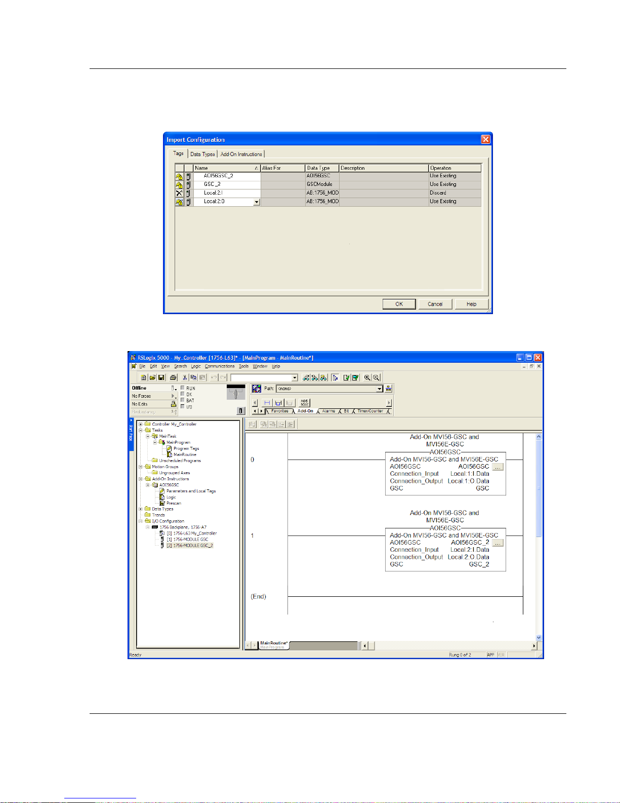
10 The following window will be displayed showing the tags to be imported:
ProSoft Technology, Inc. Page 43 of 140
April 24, 2017
Page 44

Start Here MVI56E-GSC/GSCXT ♦ CompactLogix or MicroLogix Platform
User Manual Enhanced Generic ASCII Serial Communication Module
11 Associate the I/O connection variables to the correct module. The default
values are Local:1:I and Local:1:O so these require change.
Page 44 of 140 ProSoft Technology, Inc.
April 24, 2017
Page 45
MVI56E-GSC/GSCXT ♦ CompactLogix or MicroLogix Platform Start Here
Enhanced Generic ASCII Serial Communication Module User Manual
Change the default tag names AOI56GSC and GSC to avoid conflict with
existing tags. In this step, you should append a string to the default tag
names, such as "_2", as shown in the following illustration.
12 Click OK to confirm.
The setup procedure is now complete. Save the project and download the
application to your ControlLogix processor.
ProSoft Technology, Inc. Page 45 of 140
April 24, 2017
Page 46

Start Here MVI56E-GSC/GSCXT ♦ CompactLogix or MicroLogix Platform
User Manual Enhanced Generic ASCII Serial Communication Module
1.11 Connecting Your PC to the ControlLogix Processor
There are several ways to establish communication between your PC and the
ControlLogix processor. The following steps show how to establish
communication through the serial interface.
Note: It is not mandatory that you use the processor's serial interface. You may access the
processor through whatever network interface is available on your system. Refer to your Rockwell
Automation documentation for information on other connection methods
1 Connect the right-angle connector end of the cable to your controller at the
communications port.
2 Connect the straight connector end of the cable to the serial port on your
computer.
Page 46 of 140 ProSoft Technology, Inc.
April 24, 2017
Page 47
MVI56E-GSC/GSCXT ♦ CompactLogix or MicroLogix Platform Start Here
Enhanced Generic ASCII Serial Communication Module User Manual
1.12 Downloading the Sample Program to the Processor
Note: The key switch on the front of the ControlLogix processor must be in the REM or PROG
position.
1 If you are not already online with the processor, in RSLogix 5000 open the
Communications menu, and then choose DOWNLOAD. RSLogix 5000 will
establish communication with the processor. You do not have to download
through the processor's serial port, as shown here. You may download
through any available network connection.
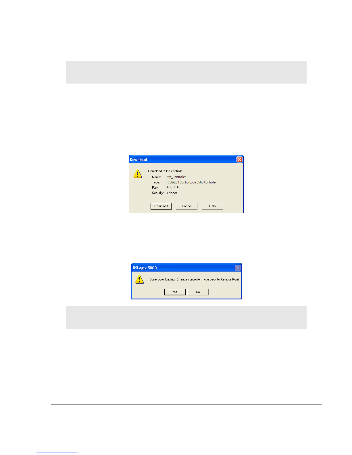
2 When communication is established, RSLogix 5000 will open a confirmation
dialog box. Click the DOWNLOAD button to transfer the sample program to the
processor.
3 RSLogix 5000 will compile the program and transfer it to the processor. This
process may take a few minutes.
4 When the download is complete, RSLogix 5000 will open another
confirmation dialog box. If the key switch is in the REM position, click OK to
switch the processor from PROGRAM mode to RUN mode.
Note: If you receive an error message during these steps, refer to your RSLogix documentation to
interpret and correct the error.
ProSoft Technology, Inc. Page 47 of 140
April 24, 2017
Page 48

MVI56E-GSC/GSCXT ♦ CompactLogix or MicroLogix Platform
User Manual Enhanced Generic ASCII Serial Communication Module
Page 48 of 140 ProSoft Technology, Inc.
April 24, 2017
Page 49

MVI56E-GSC/GSCXT ♦ CompactLogix or MicroLogix Platform MVI56E-GSC Configuration
In This Chapter
GSC.UTIL.BackplaneFail ...................................................................... 50
GSC.CONFIG.PortX (where X = 1 or 2) ................................................ 51
Changing parameters during operation ................................................. 56
Enhanced Generic ASCII Serial Communication Module User Manual
2 MVI56E-GSC Configuration
All module configuration settings, data to be exchanged, status, and error data,
except for Debug Port Ethernet settings, are contained in the RSLogix 5000
controller tag arrays.
Only the following RSLogix controller tags need to be configured for the module
to work as needed for your application.
1 The GSC.UTIL.BACKPLANEFAIL controller tag sets up a backplane
communication failure counter to monitor the health of communication
between the module and the ControlLogix processor across the ControlLogix
backplane.
ProSoft Technology, Inc. Page 49 of 140
April 24, 2017
Page 50

MVI56E-GSC Configuration MVI56E-GSC/GSCXT ♦ CompactLogix or MicroLogix Platform
User Manual Enhanced Generic ASCII Serial Communication Module
2 The GSC.CONFIG.PORT1 and GSC.CONFIG.PORT2 controller tag arrays
contain tags to configure the application serial ports. These sets of controller
tags allow you to configure typical serial port parameters, such as baud rate,
data bits, and stop bits.
2.1 GSC.UTIL.BackplaneFail
A "backplane communication failure" is any failed attempt by the module to
communicate with the ControlLogix processor. For local rack applications, where
the module is installed in the same chassis as the processor, backplane failures
can occur due to a hardware problem or Input/Output (I/O) configuration problem.
For remote rack applications, where the module is installed in a different chassis
from the processor and linked by communication adapters, such as ControlNet or
EtherNet/IP, in addition to hardware and I/O configuration problems, any failure
to communicate with the ControlLogix processor across a process network will
be considered a backplane communication failure.
The GSC.UTIL.BACKPLANEFAIL parameter specifies the number of successive
ControlLogix backplane transfer failures that must occur before the ASCII serial
communication ports are shut down. If the parameter is set to zero, the
communication ports will continue to operate under even if the module has no
communication with the processor. If the value is set greater than 0 (1 to 65535),
serial port communication will cease if the specified number of successive
communication failures occur.
The only ways to restart serial port communication after a Backplane Fail
shutdown are by Cold Boot from ladder logic, by removing and then reinserting
the module in the chassis, or by turning power to the module or chassis off and
then back on (Cold Start).
Page 50 of 140 ProSoft Technology, Inc.
April 24, 2017
Page 51

MVI56E-GSC/GSCXT ♦ CompactLogix or MicroLogix Platform MVI56E-GSC Configuration
Enhanced Generic ASCII Serial Communication Module User Manual
2.2 GSC.CONFIG.PortX
All configuration of the two ASCII application serial ports is done using the tags in
the two GSC.CONFIG.PORTX arrays.
2.2.1 Port[x].Enabled
0 = Disable port, 1 = Enable the port.
This parameter enables or disables the protocol port.
ProSoft Technology, Inc. Page 51 of 140
April 24, 2017
Page 52

MVI56E-GSC Configuration MVI56E-GSC/GSCXT ♦ CompactLogix or MicroLogix Platform
0 = No Bits
Set
1 = Bit 0 Set
2 = Bit 1 Set
4 = Bit 2 Set
8 = Bit 3 Set
Decimal
Value of
Bits
Selected
(S)
Streaming
Mode
Selected
(T)
Terminating
Characters
Selected
(M)
Message
Timeout
Selected
(D)
Intercharacter
Delay
Selected
(P)
Packet Length
Selected
Port Types
Selected by
Bitmap
0
0
S 1 1 T
2 2 M
3 1
2
M, T
4
4
D
5 1 4 D, T
6 2 4 D, M 7
1 2 4 D, M, T
8
8 P 9 1
8
P, T
10 2 8 P, M
11 1
2 8
P, M, T
12
4 8 P, D
13 1 4 8 P, D, T
14 2 4 8 P ,D, M
15 1 2 4
8
P, D, M, T
User Manual Enhanced Generic ASCII Serial Communication Module
2.2.2 Port[x].Type
0 through 15
You can use any combination of one or more termination types. When multiple
termination types are selected, the module will determine the end of the string to
be as soon as any of the selected terminating conditions becomes true. After
that, any new characters received will be considered part of a new string until the
next time a terminating condition is true.
Page 52 of 140 ProSoft Technology, Inc.
April 24, 2017
Page 53

MVI56E-GSC/GSCXT ♦ CompactLogix or MicroLogix Platform MVI56E-GSC Configuration
For Termination Type
Receive Parameters to Set
Terminating Characters
GSC.PortX.RTermCnt
GSC.PortX.RTermChar
Message Timeout
GSC.PortX.RTimeout
Intercharacter Delay
GSC.PortX.RDelay
Packet (String) Length
GSC.PortX.RPacketLen
Value
Baud Rate (bits per second)
110
110 Baud
150
150 Baud
300
300 Baud
600
600 Baud
1200
1200 Baud
2400
2400 Baud
4800
4800 Baud
9600
9600 Baud
19200
19200 Baud
384
38400 Baud
576
57600 Baud
115
115200 Baud
Value
Description
0
None
1
Odd
2
Even
3
Mark
4
Space.
Enhanced Generic ASCII Serial Communication Module User Manual
For each termination type, you must also enter values in the following parameter
configuration tags. Streaming mode is not recommended for general use, as it
creates heavy demands on the ControlLogix processor and requires time-critical
programming logic to properly process.
2.2.3 Port[x].Baudrate
This is the baud rate to use on the port. Enter the baud rate (bits per second) as
a value. All devices on this port must communicate at the same baud rate. For
example, to select 19K baud, enter 19200.
The following table describes the valid parameters for this configuration entry.
2.2.4 Port[x].Parity
Parity is a simple error checking algorithm used in serial communication. This
parameter specifies the type of parity checking to use. All devices connected to
the port must use the same parity.
ProSoft Technology, Inc. Page 53 of 140
April 24, 2017
Page 54

MVI56E-GSC Configuration MVI56E-GSC/GSCXT ♦ CompactLogix or MicroLogix Platform
Value
Description
0
No hardware or software handshaking
1
RTS/CTS hardware handshaking
2
DTR/DSR hardware handshaking
3
XON/XOFF software handshaking
User Manual Enhanced Generic ASCII Serial Communication Module
2.2.5 Port[x].DataBits
5, 6, 7 or 8
This parameter sets the number of data bits for each word used by the protocol.
All devices communicating through this port must use the same number of data
bits.
2.2.6 Port[x].StopBits
1 or 2
Stop bits signal the end of a character in the data stream. For most applications,
use one stop bit. For slower devices that require more time to re-synchronize,
use two stop bits.
All devices communicating through this port must use the same number of stop
bits.
2.2.7 Port[x].RTSOn
0 to 65535 milliseconds
This parameter sets the number of milliseconds to delay after Ready To Send
(RTS) is asserted before data will be transmitted.
2.2.8 Port[x].RTSOff
0 to 65535 milliseconds
This parameter sets the number of milliseconds to delay after the last byte of
data is sent before the RTS modem signal will be set low.
2.2.9 Port[x].Handshaking
Handshaking is a negotiation process between devices that establishes a data
connection. Select the handshaking type that best matches the needs of the
devices connected to the port.
2.2.10 Port[x].RTermCnt
0 to 12 characters
This parameter specifies the number of termination characters that define the
end of a received message. Use this parameter if you set the PORT[X].TYPE
Port[x].Type (page 52) value to 1, 3, 5, 7, 9, 11, 13 or 15.
Page 54 of 140 ProSoft Technology, Inc.
April 24, 2017
Page 55

MVI56E-GSC/GSCXT ♦ CompactLogix or MicroLogix Platform MVI56E-GSC Configuration
Enhanced Generic ASCII Serial Communication Module User Manual
2.2.11 Port[x].RTermChar
This array of up to 12 characters specifies the termination characters that define
the end of a received message. Each character occupies one position in the
array. The number of termination characters you enter here must match the
value in the PORT[X].RTERMCNT tag.
2.2.12 Port[x].RPacketLen
This parameter specifies the number of bytes of data to receive on the port
before considering an incoming message complete and transferring the data to
the processor. Use this parameter if you set the PORT[X].TYPEPort[x].Type (page
52) value to 8, 9, 10, 11, 12, 13, 14, or 15.
2.2.13 Port[x].RTimeout
This parameter specifies the number milliseconds to wait after receiving the first
character on the port before considering an incoming message complete and
automatically sending the data to the processor. Use this parameter if you set the
PORT[X].TYPE Port[x].Type (page 52) value to 2, 3, 6, 7, 10, 11, 14, or 15.
2.2.14 Port[x].RDelay
This parameter specifies the maximum number milliseconds to wait between
each character received on the port to see if more characters are coming before
considering an incoming message complete and automatically sending the data
to the processor. In practice, this can be thought of as a period of time in which
no characters are received after receiving a string of characters. Use this
parameter if you set the PORT[X].TYPE Port[x].Type (page 52) value to 4, 5, 6, 7,
10, 11, 14, or 15.
2.2.15 Port[x].WTermCnt
Not used in current release of product.
2.2.16 Port[x].WTermChar
Not used in current release of product.
2.2.17 Port[x].WPacketLen
Not used in current release of product.
ProSoft Technology, Inc. Page 55 of 140
April 24, 2017
Page 56

MVI56E-GSC Configuration MVI56E-GSC/GSCXT ♦ CompactLogix or MicroLogix Platform
User Manual Enhanced Generic ASCII Serial Communication Module
2.2.18 Port[x].WTimeout
This parameter specifies the timeout period to transmit a message out the port. A
message must be transmitted out the port within the specified timeout period.
Message transmission will be aborted if the timeout is exceeded. Use this
parameter if you set the PORT[X].TYPE Port[x].Type (page 52) to 2, 3, 6, 7, 10,
11, 14, or 15.
Note: If this parameter is left at zero, then the Port Configuration Error Word will show a value of
0400. In order to clear this error, this parameter has to be set to any non-zero value.
2.2.19 Port[x].Spare
Not used in current release of product.
2.2.20 Port[x].WMinDelay
This parameter specifies the minimum number of milliseconds to delay before
transmitting a message out the port. This pre-send delay is applied before the
RTS On time. This may be required when communicating with slow devices. Use
this parameter if you set the PORT[X].TYPE Port[x].Type (page 52) to 8, 9, 10, 11,
12, 13, 14, or 15.
2.3 Changing parameters during operation
When you change the configuration parameters in RSLogix, you must reboot or
cycle power to the module off and on before the new configuration takes effect.
You may also change the value of the GSC.ColdBoot or GSC.WarmBoot
controller tags from 0 to 1 to reboot the module from logic.
Page 56 of 140 ProSoft Technology, Inc.
April 24, 2017
Page 57

MVI56E-GSC/GSCXT ♦ CompactLogix or MicroLogix Platform Diagnostics and Troubleshooting
In This Chapter
Reading Status Data from the Module .................................................. 57
The Diagnostics Menu ........................................................................... 58
Monitoring Module Information .............................................................. 61
Monitoring Backplane Information ......................................................... 62
Data Analyzer ........................................................................................ 63
Scrolling LED Status Indicators ............................................................. 68
Ethernet LED Indicators ........................................................................ 69
Non-Scrolling LED Status Indicators ..................................................... 70
ControlLogix Processor Not in RUN or REM RUN ................................ 70
Clearing a Fault Condition ..................................................................... 70
Troubleshooting ..................................................................................... 71
Enhanced Generic ASCII Serial Communication Module User Manual
3 Diagnostics and Troubleshooting
The module provides information on diagnostics and troubleshooting in the
following forms:
LED status indicators on the front of the module provide information on the
module’s status.
Status data contained in the module can be viewed in ProSoft Configuration
Builder through the Ethernet port.
Status data values are transferred from the module to the processor.
3.1 Reading Status Data from the Module
The MVI56E-GSC module returns three separate status data areas to the
ControlLogix processor in each read block. This data is transferred to the
ControlLogix processor continuously with each read block. For a complete listing
of the status data object, refer to the Module Configuration section of this
manual.
ProSoft Technology, Inc. Page 57 of 140
April 24, 2017
This guide also includes example ladder logic showing how to extract this data
from the input image and place it in the module’s Controller Logic Tag. Refer to
Diagnostics and Troubleshooting for a discussion of the features available
through the use of this utility.
Page 58

Diagnostics and Troubleshooting MVI56E-GSC/GSCXT ♦ CompactLogix or MicroLogix Platform
User Manual Enhanced Generic ASCII Serial Communication Module
3.2 The Diagnostics Menu
The Diagnostics menu, available through the Ethernet configuration port for this
module, is arranged as a tree structure, with the Main menu at the top of the tree,
and one or more submenus for each menu command. The first menu you see
when you connect to the module is the Main menu.
3.2.1 Using the Diagnostics Menu in ProSoft Configuration Builder
Tip: You can have a ProSoft Configuration Builder Diagnostics window open for more than one
module at a time.
To connect to the module’s Configuration/Debug Ethernet port:
1 In ProSoft Configuration Builder, select the module, and then click the right
mouse button to open a shortcut menu.
Page 58 of 140 ProSoft Technology, Inc.
April 24, 2017
Page 59

MVI56E-GSC/GSCXT ♦ CompactLogix or MicroLogix Platform Diagnostics and Troubleshooting
Enhanced Generic ASCII Serial Communication Module User Manual
2 On the shortcut menu, choose DIAGNOSTICS.
3 In the Diagnostics window, click the SET UP CONNECTION button to browse for
the module’s IP address.
ProSoft Technology, Inc. Page 59 of 140
April 24, 2017
Page 60
Diagnostics and Troubleshooting MVI56E-GSC/GSCXT ♦ CompactLogix or MicroLogix Platform
User Manual Enhanced Generic ASCII Serial Communication Module
4 In the Connection Setup dialog box, click the TEST CONNECTION button to
verify that the module is accessible with the current settings.
You can also use CIPconnect® to connect to the module through a 1756-
ENBT card. Refer to Using CIPconnect® to Connect to the Module (page 24)
for information on how to construct a CIP path.
5 If the Test Connection is successful, click CONNECT.
If PCB is unable to connect to the module:
Page 60 of 140 ProSoft Technology, Inc.
April 24, 2017
Page 61

MVI56E-GSC/GSCXT ♦ CompactLogix or MicroLogix Platform Diagnostics and Troubleshooting
Enhanced Generic ASCII Serial Communication Module User Manual
1 Click the BROWSE DEVICE(S) button to open the ProSoft Discovery Service.
Select the module, then right-click and choose SELECT FOR PCB.
2 Close ProSoft Discovery Service, and click the CONNECT button again.
3 If these troubleshooting steps fail, verify that the Ethernet cable is connected
properly between your computer and the module, either through a hub or
switch (using the grey cable) or directly between your computer and the
module (using the red cable).
If you are still not able to establish a connection, contact ProSoft Technology for
assistance.
3.3 Monitoring Module Information
Use the MODULE menu to view configuration and hardware information for the
MVI56E-GSC module’s backplane and Ethernet application port.
3.3.1 Version Menu
Use the VERSION menu to view module hardware and firmware information.
ProSoft Technology, Inc. Page 61 of 140
April 24, 2017
Page 62

Diagnostics and Troubleshooting MVI56E-GSC/GSCXT ♦ CompactLogix or MicroLogix Platform
User Manual Enhanced Generic ASCII Serial Communication Module
3.3.2 Config
Use the Configuration menu to view backplane configuration settings for the
MVI56E-GSC module.
The information on this menu corresponds with the configuration information in
the Module settings in ProSoft Configuration Builder.
3.3.3 NIC Status
Use the NIC Status (Network Interface Card) menu to view configuration and
status information for the MVI56E-GSC module's Ethernet application port.
The information on this menu is useful for troubleshooting Ethernet network
connectivity problems.
3.4 Monitoring Backplane Information
Use the BACKPLANE menu to view the backplane status information for the
MVI56E-GSC module.
3.4.1 Backplane Status Menu
Click STATUS to view current backplane status, including
Number of retries
Backplane Status
Fail Count
Number of words read
Number of words written
Number of words parsed
Error count
During normal operation, the Read, Write, and Parsing values should increment
continuously, while the error value should not increment.
The status values on this menu correspond with the members of the MVI56EGSC Status object.
Page 62 of 140 ProSoft Technology, Inc.
April 24, 2017
Page 63

MVI56E-GSC/GSCXT ♦ CompactLogix or MicroLogix Platform Diagnostics and Troubleshooting
Enhanced Generic ASCII Serial Communication Module User Manual
3.5 Data Analyzer
The Data Analyzer mode allows you to view all bytes of data transferred on each
port. Both the transmitted and received data bytes are displayed. Use of this
feature is limited without a thorough understanding of the protocol.
3.5.1 Starting the Data Analyzer
Turn on the Data Analyzer feature so you can monitor the data exchanged
between the processor and the module. Start ProSoft Configuration Builder
(PCB) and perform the following sequence.
1 Start by right-clicking on the module name and left-clicking DIAGNOSTICS on
the context menu.
This opens the main Diagnostics screen.
ProSoft Technology, Inc. Page 63 of 140
April 24, 2017
Page 64

Diagnostics and Troubleshooting MVI56E-GSC/GSCXT ♦ CompactLogix or MicroLogix Platform
User Manual Enhanced Generic ASCII Serial Communication Module
2 Left-click on the button to setup the Data Analyzer feature as shown.
3 Left-click on the button to start the Data Analyzer feature.
The following illustration shows an example of the Data Analyzer output with no
traffic being passed on the serial network. With no transmitted data to display,
the Data Analyzer shows only the "_TT_" timing markers, called "Time Ticks".
The time between Time Ticks is adjustable and can be set in the Data Analyzer
Setup dialog box, as previously seen.
In this example the Time Ticks have been set to 50 milliseconds. During actual
transmission of data, the Time Ticks will appear interspersed within the data
bytes and indicate the configured time interval. This information can be valuable
for troubleshooting certain kinds of communication problems.
Page 64 of 140 ProSoft Technology, Inc.
April 24, 2017
Page 65

MVI56E-GSC/GSCXT ♦ CompactLogix or MicroLogix Platform Diagnostics and Troubleshooting
Character
Definition
[ ]
Data enclosed in [square brackets] represent data received on the port.
< >
Data enclosed in <angle brackets> represent data transmitted on the port.
<R+>
These characters are inserted when the Ready To Send (RTS) line is driven high
on the port, just before data transmission begins.
<R->
These characters are inserted when the RTS line is dropped low on the port,
indicating the end of transmission.
<CS>
These characters are displayed when the Clear to Send (CTS) line is recognized
high. These characters will appear only when hardware handshaking is enabled in
the port configuration (Use CTS = 1). Most applications do not require the use of
hardware handshaking.
_TT_
These characters are displayed when the "Time Tick" is set to any value other than
"No Ticks". Time Ticks will be displayed at the interval selected in the Data
Analyzer Setup dialog box and will be interspersed with any data received on the
port. ASCII Characters or Decimal byte values shown between any two Time Ticks
will indicate the characters received on the port during that time interval.
Enhanced Generic ASCII Serial Communication Module User Manual
The Data Analyzer can display the following special characters.
3.5.2 Stopping the Data Analyzer
Important: When in analyzer mode, program execution will slow down. Only use this tool during a
troubleshooting session. Before disconnecting from the Config/Debug port, please stop the data
analyzer. This action will allow the module to resume its normal high speed operating mode.
ProSoft Technology, Inc. Page 65 of 140
April 24, 2017
Page 66

Diagnostics and Troubleshooting MVI56E-GSC/GSCXT ♦ CompactLogix or MicroLogix Platform
User Manual Enhanced Generic ASCII Serial Communication Module
3.5.3 Data Analyzer Tips
For most applications, HEX is the best format to view the data, and this does
include ASCII based messages (because some characters will not display in the
Diagnostics window in ASCII mode, and, by capturing the data in HEX, you can
figure out what the corresponding ASCII characters are supposed to be).
The Time Tick value is a timing mark. The module will print a _TT_ every so
many milliseconds. The Time Tick setting is adjustable in the Data Analyzer
Setup dialog box. Usually 10 milliseconds works best for most applications.
To save a capture file of your Diagnostics session
1 After you have selected the Port, Format, and Tick, you are now ready to
start a capture of this data.
2 When you have captured the data you want to save, click again to stop
capturing data.
You have now captured and saved the data to a file on your PC. This file can
now be used in analyzing the communication traffic on the line and assist in
determining communication errors. The log file name is PCB-Log.txt, located in
the root directory of your hard drive (normally Drive C).
Once you have everything that shows up on the Diagnostics screen being logged
to a file called PCB-Log.txt, you can email this file to ProSoft Technical Support
for help with the analysis of communication problems.
Page 66 of 140 ProSoft Technology, Inc.
April 24, 2017
Page 67

MVI56E-GSC/GSCXT ♦ CompactLogix or MicroLogix Platform Diagnostics and Troubleshooting
Enhanced Generic ASCII Serial Communication Module User Manual
To begin the display of communications data, start the Data Analyzer. When the
Data Analyzer is running, you should see something like this.
The <R+> means that the module is transitioning the communications line to a
transmit state.
All characters shown in <> brackets are characters being sent out by the module.
The <R-> shows when the module is done transmitting data and is now ready to
receive information.
All characters shown in [ ] braces are information being received from another
device by the module.
After capturing traffic for a minute or two, stop the Data Analyzer.
ProSoft Technology, Inc. Page 67 of 140
April 24, 2017
Page 68

Diagnostics and Troubleshooting MVI56E-GSC/GSCXT ♦ CompactLogix or MicroLogix Platform
Message
Meaning
"Boot"
Module is initializing its operating system
"Waiting for Processor
Connection..."
Module is not able to establish a backplane connection with
the ControlLogix PAC. Possible causes:
Ladder logic or AOI is not loaded on processor
Module is located in a different slot than the one
configured in the ladder logic/AOI
Module I/O properties are invalid
Processor is not in RUN or REM RUN mode
"INIT"
Module is beginning its firmware initialization
"Ladder Logic Configuration
Required"
Module is waiting for valid module configuration data from
ladder logic. Check that module configuration parameters are
set to valid values in the ladder logic controller tags
"UPDATING"
Module is performing a firmware update, initiated from the
web page.
"STOP"
Module firmware is stopping after receiving a "Cold Boot"
request, which forces an automatic re-start, same as from
power-up
"MVI-56E-GSC <Version#> Last
Config: <LCfgDate> Config P1:
<TermType> <BaudRate>,
<Parity>, <DataBits>, <StopBits>,
<RS_Type>, P2: <TermType>
<BaudRate>, <Parity>, <DataBits>,
<StopBits>, <RS_Type>"
After power up and every reconfiguration reboot, the module
will display the configuration of both ports. This message will
scroll through once and not be repeated until the next reboot.
The message contains:
<Version#> Firmware revision number, as in "V2.01"
<LCfgDate> Date of last configuration change (reboot)
<TermType>: Termination Type; options are:
STREAM - Streaming
TERM - Terminating Characters
DELAY - Intercharacter Delay
PACKET - Packet Length
MSGTO - Message Timeout
<BaudRate>: 115200 / 57600 / 38400 / 19200 / 9600/
4800 / 2400 / 1200 / 600 / 300
<Parity>: None / Even / Odd
<DataBits>: 7 / 8
<StopBits>: 1 / 2
<RS_Type>: RS-232 / RS-422 / RS-485
User Manual Enhanced Generic ASCII Serial Communication Module
3.6 Scrolling LED Status Indicators
The scrolling LED display indicates the module’s operating status as follows:
Initialization Messages
Page 68 of 140 ProSoft Technology, Inc.
April 24, 2017
Page 69

MVI56E-GSC/GSCXT ♦ CompactLogix or MicroLogix Platform Diagnostics and Troubleshooting
Message
Meaning
"E003"
Startup sequence failed, module failed to initialize
"E005"
Displayed during startup if there is an error opening
application serial Port 1(P1)
"E006"
Displayed during startup if there is an error opening
application serial Port 2 (P2)
"E008"
Displayed during startup if either of the two application serial
ports fails to open after a second attempt
"E009"
Displayed during startup if there is an error setting up the
signal handlers)
Message Component
Meaning
<Backplane Status>
"OK": Module is communicating with processor
<IP Address>
Module IP address
<Port1 Status>
<Port2 Status>
"Enabled": Port is enabled, sending and receiving possible
"Disabled": Port is disabled, no sending or receiving possible
LED
State
Description
Data
OFF
Ethernet connected at 10Mbps duplex speed
AMBER Solid
Ethernet connected at 100Mbps duplex speed
Link
OFF
No physical network connection is detected. No Ethernet
communication is possible. Check wiring and cables.
GREEN Solid
or Blinking
Physical network connection detected. This LED must be ON solid
for Ethernet communication to be possible.
Enhanced Generic ASCII Serial Communication Module User Manual
Initialization Error Messages
During initialization, if the module detects a unrecoverable fault that will prevent
communication, an error message will be displayed. If any of these errors persist
after repeated reboot attempts, contact ProSoft Technology Technical Support
for further assistance.
Operation Message
After the initialization step, the following message pattern will be repeated on the
scrolling LED display.
<Backplane Status> <IP Address> <Backplane Status> <Port1 Status> <Port2
Status>
3.7 Ethernet LED Indicators
The Ethernet LEDs indicate the module's Ethernet port status as follows:
ProSoft Technology, Inc. Page 69 of 140
April 24, 2017
Page 70

Diagnostics and Troubleshooting MVI56E-GSC/GSCXT ♦ CompactLogix or MicroLogix Platform
LED Label
Color
Status
Indication
APP
Red or
Green
OFF
The module is not receiving adequate power or is not securely
plugged into the rack. May also be OFF during configuration
download.
GREEN
The MVI56E-GSC is working normally.
RED
The most common cause is that the module has detected a
communication error during operation of an application port.
The following conditions may also cause a RED LED:
The firmware is initializing during startup
The firmware detects an on-board hardware problem
during startup
Failure of application port hardware during startup
The module is shutting down
The module is rebooting due to a ColdBoot or WarmBoot
request from the ladder logic or Debug Menu
OK
Red or
Green
OFF
The module is not receiving adequate power or is not securely
plugged into the rack.
GREEN
The module is operating normally.
RED
The module has detected an internal error or is being
initialized. If the LED remains RED for over 10 seconds, the
module is not working. Remove it from the rack and re-insert it
to restart its internal program.
ERR
Red Not used.
User Manual Enhanced Generic ASCII Serial Communication Module
3.8 Non-Scrolling LED Status Indicators
The non-scrolling LEDs indicate the module’s operating status as follows:
3.9 ControlLogix Processor Not in RUN or REM RUN
Whenever the module detects that the processor has gone out of the RUN mode
(that is, the processors faults or is set to PGM (Program mode), the application
ports can be shut down as prescribed in the user configuration. When the
processor is returned to a running state, the module will resume communication
on the serial networks.
3.10 Clearing a Fault Condition
Typically, if the OK LED on the front of the module turns RED for more than ten
seconds, a hardware problem has been detected in the module or the program
has exited.
Page 70 of 140 ProSoft Technology, Inc.
April 24, 2017
Page 71

MVI56E-GSC/GSCXT ♦ CompactLogix or MicroLogix Platform Diagnostics and Troubleshooting
Problem Description
Steps to take
Processor Fault
Verify that the module is plugged into the slot that has been configured
for the module in the I/O Configuration of RSLogix.
Verify that the slot location in the rack has been configured correctly in
the ladder logic.
Processor I/O LED
flashes
This indicates a problem with backplane communications. A problem
could exist between the processor and any installed I/O module, not just
the MVI56E-GSC. Verify that all modules in the rack are correctly
configured in the ladder logic.
Problem Description
Steps to take
MVI56E modules with
scrolling LED display:
<Backplane Status>
condition reads ERR
This indicates that backplane transfer operations are failing. Connect to
the module’s Configuration/Debug port to check this.
To establish backplane communications, verify the following items:
The processor is in RUN or REM RUN mode.
The backplane driver is loaded in the module.
The module is configured for read and write data block transfer.
The ladder logic handles all read and write block situations.
The module is properly configured in the processor I/O configuration
and ladder logic.
OK LED remains RED
The program has halted or a critical error has occurred. Connect to the
Configuration/Debug port to see if the module is running. If the program
has halted, turn off power to the rack, remove the card from the rack and
re-insert the card in the rack, and then restore power to the rack.
Enhanced Generic ASCII Serial Communication Module User Manual
To clear the condition, follow these steps:
1 Turn off power to the rack.
2 Remove the card from the rack.
3 Verify that all jumpers are set correctly.
4 If the module requires a Compact Flash card, verify that the card is installed
correctly.
5 Re-insert the card in the rack and turn the power back on.
6 Verify correct configuration data is being transferred to the module from the
ControlLogix controller.
If the module's OK LED does not turn GREEN, verify that the module is inserted
completely into the rack. If this does not cure the problem, contact ProSoft
Technology Technical Support.
3.11 Troubleshooting
Use the following troubleshooting steps if you encounter problems when the
module is powered up. If these steps do not resolve your problem, please contact
ProSoft Technology Technical Support.
Processor Errors
Module Errors
ProSoft Technology, Inc. Page 71 of 140
April 24, 2017
Page 72

MVI56E-GSC/GSCXT ♦ CompactLogix or MicroLogix Platform
User Manual Enhanced Generic ASCII Serial Communication Module
Page 72 of 140 ProSoft Technology, Inc.
April 24, 2017
Page 73

MVI56E-GSC/GSCXT ♦ CompactLogix or MicroLogix Platform Reference
In This Chapter
Product Specifications ........................................................................... 73
General Concepts ................................................................................. 75
Normal Data Transfer ............................................................................ 85
Special Function Blocks ........................................................................ 90
Using the Sample Add-On Instruction ................................................... 92
Using the Optional Add-On Instruction ................................................ 112
Using the Sample Program - RSLogix 5000 Version 15 and earlier .... 122
Adding the Sample Ladder to an Existing Application ......................... 127
Error/Configuration Word..................................................................... 130
Cable Connections .............................................................................. 130
Enhanced Generic ASCII Serial Communication Module User Manual
4 Reference
4.1 Product Specifications
The Enhanced Generic ASCII Serial Communication Modules allow Rockwell
Automation® ControlLogix® Programmable Automation Controllers (PACs) to
easily interface with serial devices using non-specific ASCII character text string
or byte value serial communication protocols.
MVI56E-GSC enhancements include local and remote diagnostics through the
module’s Ethernet port, and CIPconnect
Rockwell Automation ControlNet™and EtherNet/IP™ networks.
The MVI56E-GSC module is a fast and easy way to add two fully configurable
serial communication ports to the ControlLogix platform, eliminating the need to
use the front port of the processor, or consume valuable processor time sending
and receiving serial messages.
The module is a single-slot, backplane-compatible solution. Each port is capable
of sending and receiving large ASCII character strings or byte streams of up to
4096 characters or bytes. Many different serial communication devices can be
integrated into the ControlLogix platform by building upon the sample ladder logic
provided for this module.
ProSoft Technology, Inc. Page 73 of 140
April 24, 2017
4.1.1 General Specifications
Backward-compatible with previous MVI56-GSC version
Single Slot - 1756 ControlLogix® backplane compatible
10/100 MB Ethernet port for network configuration and diagnostics with Auto
Cable Crossover Detection
User-definable module data memory mapping of up to 10,000 16-bit registers
®
technology for bridging though
Page 74

Reference MVI56E-GSC/GSCXT ♦ CompactLogix or MicroLogix Platform
User Manual Enhanced Generic ASCII Serial Communication Module
CIPconnect®-enabled network diagnostics and monitoring using ControlLogix
1756-ENxT modules and EtherNet/IP® pass-thru communications
Sample Ladder Logic or Add-On Instruction (AOI) used for data transfers
between module and processor and for module configuration
4-character, scrolling, alphanumeric LED display of status and diagnostic
data in plain English
ProSoft Discovery Service (PDS) software finds the module on the network
and assigns a temporary IP address to facilitate module access
4.1.2 Functional Specifications
The MVI56E-GSC and MVI56E-GSCXT are functionally identical. The
MVI56E-GSC is for normal process and control environments. The MVI56E-
GSCXT is conformal coated for extra protection in harsh or caustic
environments and operates in extreme high or low temperature
environments.
Both modules transfer data in the largest possible I/O image block sizes,
which optimizes data through-put and update time.
Both modules appear to the ControlLogix processor as input/output (I/O)
modules, rather than communication modules.
Two ASCII serial communication ports:
o Can independently transmit and/or receive ASCII character strings and
serial byte streams
o Each port is individually configurable
Receive ASCII character strings or byte streams up to 4096 characters in
length
Received packet termination types:
o Stream mode (no packet termination)
o Receipt of specified character or characters
o Message length timeout
o Intercharacter spacing timeout
o Packet size limit (number of received characters/bytes)
Module configuration and communication configuration data is transferred to
the module via predefined sample ladder logic
Module error and status conditions returned to processor for diagnostic
purposes
o Module status
o Port error status word (bit mapped)
o Port receive state
o Port receive character count
o Port receive block count
o Port transmit state
o Port transmit character count
o Port transmit block count
Page 74 of 140 ProSoft Technology, Inc.
April 24, 2017
Page 75

MVI56E-GSC/GSCXT ♦ CompactLogix or MicroLogix Platform Reference
Specification
Description
Backplane Current Load
800 mA @ 5 VDC
3 mA @ 24 VDC
Operating Temperature
0°C to 60°C (32°F to 140°F) - MVI56E-GSC
-25°C to 70°C (-13°F to 158°F) - MVI56E-GSCXT
Storage Temperature
-40°C to 85°C (-40°F to 185°F)
Shock
30 g operational
50 g non-operational
Vibration: 5 g from 10 to 150 Hz
Relative Humidity
5% to 95% (without condensation)
LED Indicators
Battery Status (ERR)
Application Status (APP)
Module Status (OK)
4-Character, Scrolling, AlphaNumeric LED Display
Shows Module, Version, IP, Port Status, P1 and
P2 Settings, and Error Information
Debug/Configuration Ethernet port (E1 - Config)
Ethernet Port
10/100 Base-T, RJ45 Connector, for CAT5 cable
Link and Activity LED indicators
Auto-crossover cable detection
Serial Application ports (P1 & P2)
Software configurable
communication parameters
Baud rate: 110 baud to 115.2 kbps
RS-232, RS-485, and RS-422
Parity: none, odd or even
Data bits: 5, 6, 7, or 8
Stop bits: 1 or 2
RTS on/off delay: 0 to 65535 milliseconds
Full hardware handshaking control (optional)
Radio and modem support
App Ports (P1, P2)
RJ45 (DB-9M with supplied adapter cable)
Configurable RS-232 hardware handshaking
500V Optical isolation from backplane
RS-232, RS-422, RS-485 jumper-select, per port
RX (Receive) and TX (Transmit) LEDs, each port
Shipped with Unit
RJ45 to DB-9M cables for each serial port
5 foot Ethernet Straight-Thru Cable (Gray)
Enhanced Generic ASCII Serial Communication Module User Manual
4.1.3 Hardware Specifications
ProSoft Technology, Inc. Page 75 of 140
April 24, 2017
Page 76

Reference MVI56E-GSC/GSCXT ♦ CompactLogix or MicroLogix Platform
User Manual Enhanced Generic ASCII Serial Communication Module
4.2 General Concepts
The following discussion explains several concepts that are important for
understanding module operation.
4.2.1 Backplane Data Transfer
The MVI56E-GSC module communicates directly with the ControlLogix either
through the backplane, when in a local chassis, or over a process I/O network
(like ControlNet or EtherNet/IP) when in a remote chassis. Data travels between
the module and the ControlLogix processor across the backplane or I/O network
using the module's input and output images. The I/O image update frequency is
determined by the scheduled Requested Packet Interval (RPI) time set by the
user for the module, as well as the overall communication load on the module.
Typical updates are in the range of 1 to 10 milliseconds.
Data received on the application ports is placed in the module's input image. This
data is processed by the logic in the ControlLogix processor. The input image
size for the module is set to 500 bytes. This large data area permits fast
throughput of data between the module and the processor.
The processor inserts data in the module's output image to transfer that data to
the module. The module's program extracts the data and transmits it out the
communication port or ports. The output image size for the module is set to 496
bytes. This large data area permits fast throughput of data from the processor to
the module.
The following illustration shows the data transfer method used to move data
between the ControlLogix processor, the MVI56E-GSC module and the serial
devices.
Page 76 of 140 ProSoft Technology, Inc.
April 24, 2017
Page 77
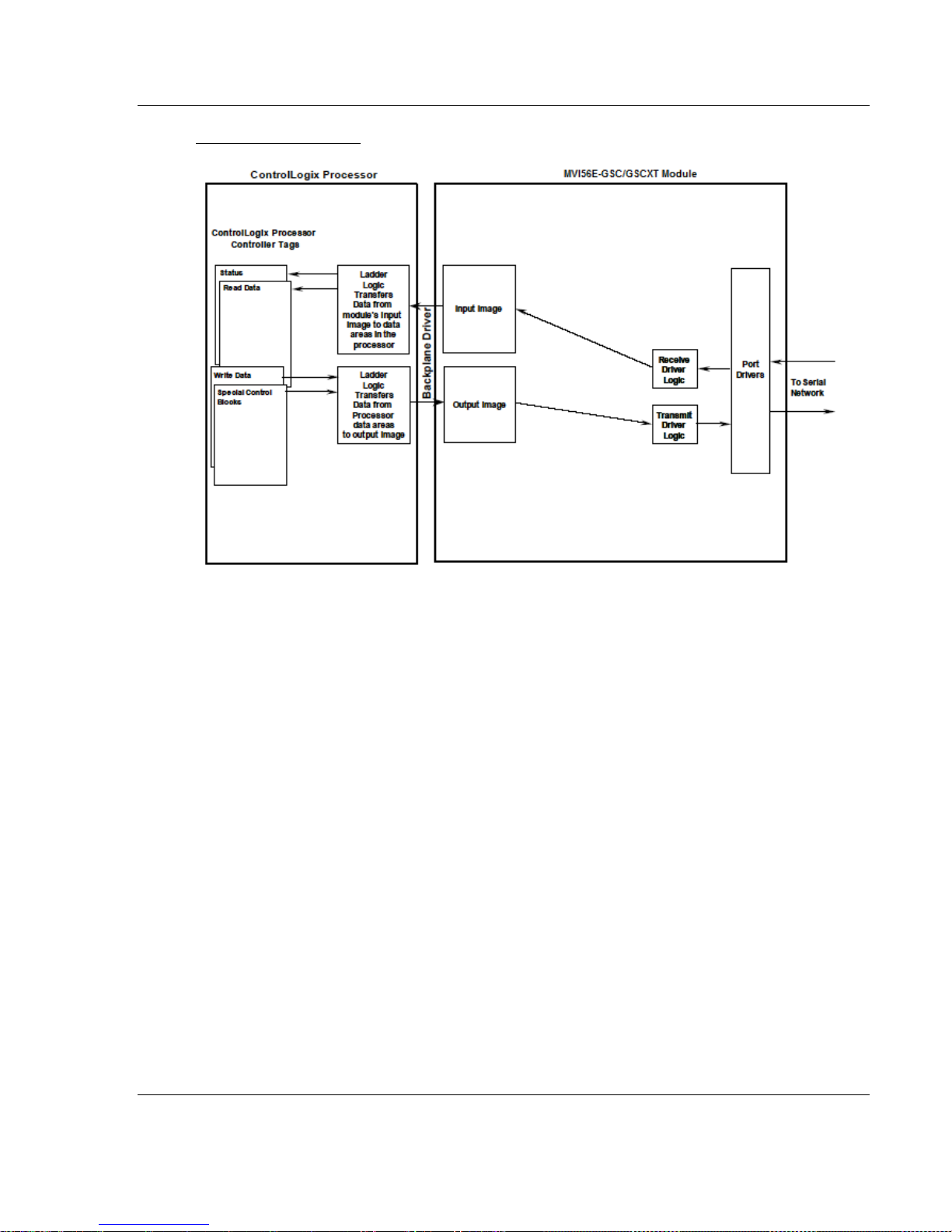
MVI56E-GSC/GSCXT ♦ CompactLogix or MicroLogix Platform Reference
Enhanced Generic ASCII Serial Communication Module User Manual
MVI56E-GSC Module
As shown in the illustration above, all data transferred between the module and
the processor over the backplane is through the input and output images. Ladder
logic must be written in the ControlLogix processor to interface the input and
output image data with data defined in the Controller Tags. Your ladder logic
must handle and interpret all data received on the application ports and
transferred into the input image. You must also construct messages to be
transferred out of the application ports by building the messages in the
appropriate controller tags for transfer to the output image of the module.
4.2.2 Data Flow between MVI56E-GSC Module and ControlLogix
Processor
The following topics describe the flow of data between the two pieces of
hardware (ControlLogix processor and MVI56E-GSC module) and other devices
attached to the application ports. Each application port on the module is
configured independently to interface with serial communication devices. The
sections below show the three possible types of communication devices that can
be attached to the application ports: write-only, read-only and read-write.
ProSoft Technology, Inc. Page 77 of 140
April 24, 2017
Page 78

Reference MVI56E-GSC/GSCXT ♦ CompactLogix or MicroLogix Platform
User Manual Enhanced Generic ASCII Serial Communication Module
Write-Only Devices
Write-only devices are those that only send data to the module. An example of
this type of device is a barcode reader which has been configured to only send
data and is not expecting to receive data.
In this situation, the application port on the MVI56E-GSC module will never have
to transmit data. All data received from the barcode reader will be passed from
the module to the ControlLogix processor through the module’s input image.
Ladder logic in the processor must handle the data received from the module.
The output image on the module will only be used to inform the module when the
input image has been processed. This is accomplished by copying the Byte 499
in the input image to Byte 0 of the output image.
The data flow diagram for a write-only device is shown below:
Page 78 of 140 ProSoft Technology, Inc.
April 24, 2017
Page 79
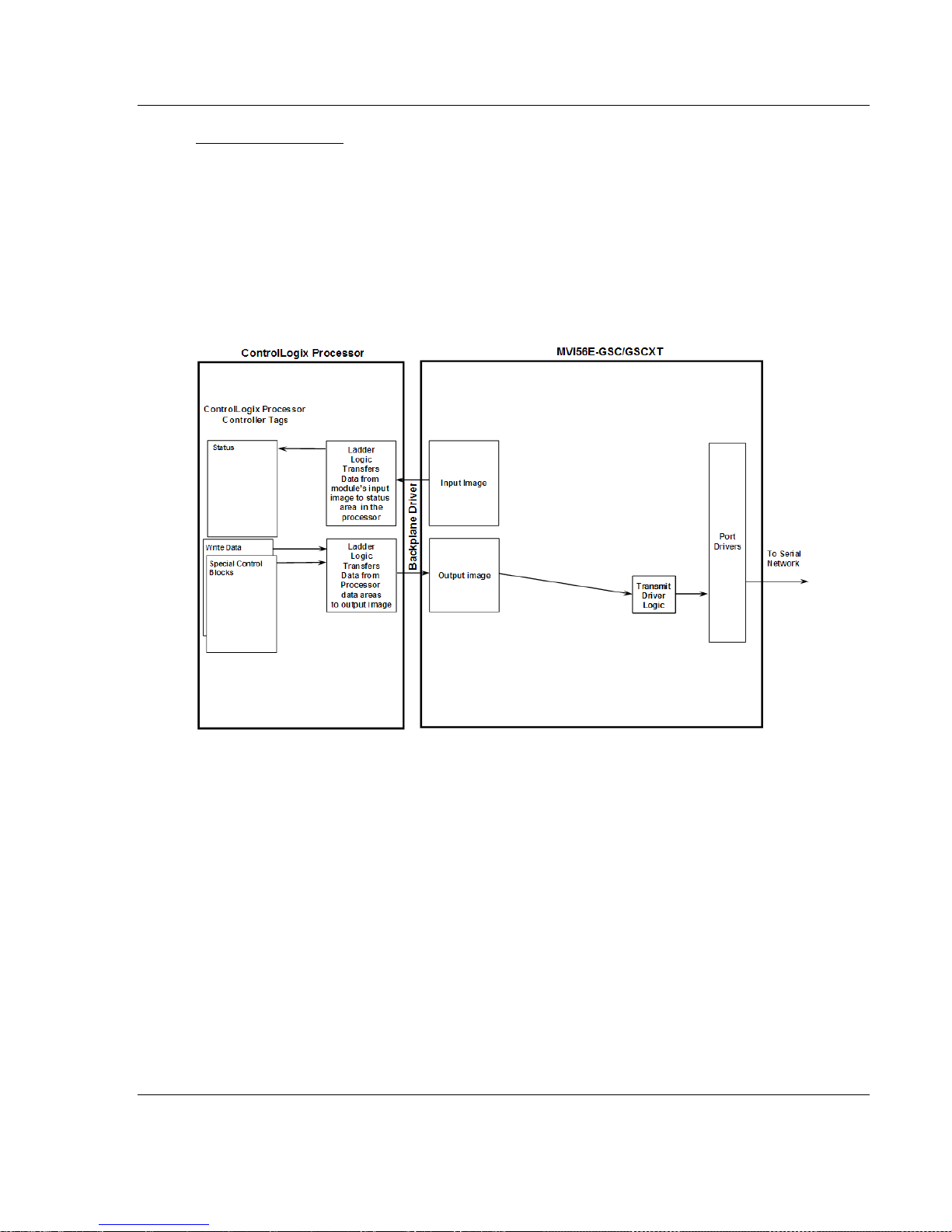
MVI56E-GSC/GSCXT ♦ CompactLogix or MicroLogix Platform Reference
Enhanced Generic ASCII Serial Communication Module User Manual
Read-Only Devices
Read-Only devices are those that only receive data from the module. An
example of this type of device is a printer. The printer will generate output or be
controlled based on the data it receives on its communication port.
Ladder logic is used to construct the write blocks to be sent to the module. When
the module receives a new write block containing data, it will transmit the data
out the port. The Block Sequence Number used in the write block should be the
one received on the last read block.
The data flow diagram for a read-only device is shown below:
ProSoft Technology, Inc. Page 79 of 140
April 24, 2017
Page 80

Reference MVI56E-GSC/GSCXT ♦ CompactLogix or MicroLogix Platform
User Manual Enhanced Generic ASCII Serial Communication Module
Read-Write Devices
Read-write devices are those that both send and receive data. An example of
this type of device is a computer terminal. A terminal will send data entered on
the keyboard out its serial port and display any data received on its port on the
monitor.
All data received from the terminal keyboard will be routed to the ControlLogix
processor through the MVI56E-GSC’s input image. Data to be written to the
terminal screen will be sent to the module using the output image. The module
will send new data from the output image out the application port to the terminal.
The example shipped with the module can be used to interface with a terminal to
echo back all characters received.
The data flow diagram for a read-write device is shown below:
Page 80 of 140 ProSoft Technology, Inc.
April 24, 2017
Page 81

MVI56E-GSC/GSCXT ♦ CompactLogix or MicroLogix Platform Reference
0 = No Bits
Set
1 = Bit 0 Set
2 = Bit 1 Set
4 = Bit 2 Set
8 = Bit 3 Set
Decimal
Value of
Bits
Selected
(S)
Streaming
Mode
Selected
(T)
Terminating
Characters
Selected
(M)
Message
Timeout
Selected
(D)
Intercharacter
Delay
Selected
(P)
Packet Length
Selected
Port Types
Selected by
Bitmap
0 0 S 1 1
T
2
2
M
3 1
2
M, T
4 4 D 5 1 4
D, T 6
2
4 D, M
7 1 2 4 D, M, T
8
8
P
9 1 8 P, T
10
2
8
P, M
11 1
2 8
P, M, T
12
4 8 P, D
13 1 4 8 P, D, T
14 2 4 8 P ,D, M
15 1 2 4
8
P, D, M, T
Enhanced Generic ASCII Serial Communication Module User Manual
4.2.3 Termination of Received Data
When data is received on either of the application ports, you must define in the
configuration when this data will be transferred to the ControlLogix processor.
Within the module, this is known as the termination type for port. When the
termination condition is met, the data will be sent from the port’s receive buffer
(data area of 4096 bytes) to the processor using the input image. This
termination type is set using a bit-mapped value, entered into the
GSC.CONFIG.PORTX.TYPE field of the configuration controller tags.
Termination Mode Selection Chart
ProSoft Technology, Inc. Page 81 of 140
April 24, 2017
Page 82

Reference MVI56E-GSC/GSCXT ♦ CompactLogix or MicroLogix Platform
User Manual Enhanced Generic ASCII Serial Communication Module
Note: For each termination type, you must also enter the corresponding parameters in the
following configuration tags:
GSC.PortX.RtermCnt
GSC.PortX.RtermCnt
GSC.PortX.RpacketLen
GSC.PortX.Rtimeout
GSC.PortX.Rdelay
GSC.PortX.WtermCnt
GSC.PortX.WtermChar
GSC.PortX.WpacketLen
GSC.PortX.Wtimeout
GSC.PortX.Wdelay
GSC.PortX.WMinDelay
Termination Type Field
If none of the bits are set (Type=0), the port will be configured for stream mode.
Any characters received on the port are immediately sent to the processor. The
processor must buffer and assemble a packet of information if this mode is
selected. If the data can be handled by the processor in this mode and it is
appropriate for your application, this is the fastest method of communication
between the device and the processor. However, stream mode tends to be
processor-intensive and does not work well in larger applications due to the
potential for loss of data. For larger applications, consider using one of the other
modes that allows the module to buffer incoming data from complete messages
before transferring it to the processor.
Any combination of termination types/bit settings is acceptable to the module and
should be set to match the device on the specific port. An example of each
termination type is given below.
Termination character(s) used
Page 82 of 140 ProSoft Technology, Inc.
April 24, 2017
Page 83

MVI56E-GSC/GSCXT ♦ CompactLogix or MicroLogix Platform Reference
Enhanced Generic ASCII Serial Communication Module User Manual
Message timeout used
Intercharacter delay timeout used
Packet size limit used
ProSoft Technology, Inc. Page 83 of 140
April 24, 2017
Page 84

Reference MVI56E-GSC/GSCXT ♦ CompactLogix or MicroLogix Platform
0 = No Bits
Set
1 = Bit 0 Set
2 = Bit 1 Set
4 = Bit 2 Set
8 = Bit 3 Set
Decimal Value
of Bits
Selected
(S)
Streaming
Mode
Selected
(T)
Terminating
Characters
Selected
(M)
Message
Timeout
Selected
(D)
Intercharacter
Delay Selected
(P)
Packet
Length
Selected
Port Types
Selected by
Bitmap
0
0
S
1 1
T
2
2
M
3 1
2
M, T
4
4
D
5 1 4 D, T
6
2
4 D, M
7 1 2 4
D, M, T
8
8 P 9 1
8
P, T
10
2
8
P, M
11 1
2 8
P, M, T
12
4 8 P, D
13 1 4
8
P, D, T
14
2 4 8
P ,D, M
15 1 2 4
8
P, D, M, T
For Termination Type
Receive Parameters to Set
Terminating Characters
GSC.PortX.RtermCnt
GSC.PortX.RTermChar
Message Timeout
GSC.PortX.RTimeout
Intercharacter Delay
GSC.PortX.RDelay
Packet (String) Length
GSC.PortX.RPacketLen
User Manual Enhanced Generic ASCII Serial Communication Module
Termination Mode Selection Chart
Note: For each termination type, you must also enter values in the following
parameter configuration tags:
Streaming mode is not recommended for general use, as it creates heavy
demands on the ControlLogix processor and requires time-critical programming
logic to properly process.
Page 84 of 140 ProSoft Technology, Inc.
April 24, 2017
Page 85

MVI56E-GSC/GSCXT ♦ CompactLogix or MicroLogix Platform Reference
Byte Offset
Description
0
Block Sequence Number (Read Block Byte 499 value sent by module)
1 to 2
Intercharacter delay for this message (milliseconds between characters)
3 to 4
Number of characters to transmit on Port 1 (0 to 200)
5 to 204
Port 1 data to transmit
205 to 250
Reserved
Byte Offset
Description
251 to 252
Intercharacter delay for this message (milliseconds between characters)
253 to 254
Number of characters to transmit on Port 2 (0 to 200)
255 to 454
Port 2 data to transmit
455 to 495
Reserved
Enhanced Generic ASCII Serial Communication Module User Manual
4.3 Normal Data Transfer
Normal data transfer includes the transferring of data received or to be
transmitted on the ports and the status data. These data are transferred through
read (input image) and write (output image) blocks. Refer to Sample Logic
Program for a description of the data objects used with the blocks and the ladder
logic required. The following topics describe the function and structure of each
block.
4.3.1 Block Request from the Processor to the Module
These blocks of data transfer information from the ControlLogix processor to the
module. The structure of the output image used to transfer this data is shown
below:
Port 1
Port 2
To set up a message to be transmitted, the simple example ladder expects the
user to do the following in this order, either manually or by writing additional
process logic:
Load the character codes for the outgoing message string into the controller
tag GSC.Px_Data.WriteString (where x = 1 for Port 1 or 2 for Port 2)
Set the tag GSC.Px_Data.WriteLength to the number of characters to send
Once the number of characters to transmit in the write block is set greater than
zero (value in word at bytes 3 & 4 and/or 253 & 254), the ladder logic program
will trigger the Process Write Block function and move a new sequence number
value into Byte 0 of the output image. This Block Sequence Number will be the
value received in the most recently received Read Block. If the selected port is
not already busy, the data in the block will be moved to the port’s transmit buffer
and sent out the port.
ProSoft Technology, Inc. Page 85 of 140
April 24, 2017
Page 86

Reference MVI56E-GSC/GSCXT ♦ CompactLogix or MicroLogix Platform
Byte Offset
Description
0
Reserved
1 to 2
Number of characters (0 to 200) in Port 1 receive block (5 to 204). If the receive
data in the module is larger than 200 bytes, multiple blocks will be transferred. Any
block with a value of -1 in this field represents the first or continuation block and the
block contains 200 bytes of data. The last block of data will contain a positive
number in this field that represents the number of characters in the last block.
3 to 4
Number of characters transmitted (0 to 200) from last block write Port 1
5 to 204
Port 1 data received
205 to 209
Reserved
Byte Offset
Description
210 to 211
Program cycle counter
212 to 215
Product name as ASCII string
216 to 219
Revision level as ASCII string
220 to 223
Operating system level as ASCII string
224 to 227
Run number as ASCII string
User Manual Enhanced Generic ASCII Serial Communication Module
For devices that do not buffer received data, when interfacing with a modem in
command mode, or when simulating keyboard or keypad entry, inter-character
delays may be required. In order to pace the characters for the write operation,
an inter-character delay value can be sent with each write message.
For example, if the port is tied to a device that expects input with delays of 200
milliseconds between each character, set the Inter-character Delay word (Bytes 1
& 2 for Port 1 or Bytes 251 & 252 for Port 2) to a value of 200 in the module’s
output image using processor ladder logic. The message will be transmitted with
a 200-millisecond wait period between each character. Because this delay value
is sent from the processor for each write message, the inter-character delay can
be set independently for each message.
For example, when writing AT commands to a dial-up modem, an inter-character
delay of 100 milliseconds may be required for dialing. But, when the modem has
made its connection and is ready for data transfer, the Inter-character Delay
might need to be set to 0. When the delay is set to 0, the whole packet of data
will be placed in the module’s transmit buffer at one time and all characters will
be sent one after the other with no delay in between.
4.3.2 Read Block
The module buffers the data received on its application serial ports in individual
port receive buffers until one of the specified termination condition is recognized.
The module will then transfer the received block of data from the port buffer to
the controller. Read data blocks transfer information from the module to the
ControlLogix processor.
The structure of the input image used to transfer this data is shown below.
Port 1
Module Status
Page 86 of 140 ProSoft Technology, Inc.
April 24, 2017
Page 87

MVI56E-GSC/GSCXT ♦ CompactLogix or MicroLogix Platform Reference
Byte Offset
Description
228 to 229
Number of blocks transferred from module to processor
230 to 231
Number of blocks transferred from processor to module
232 to 233
Number of blocks parsed by module
234 to 235
Number of block errors in module
Byte Offset
Description
236 to 237
Port 1 receive state:
-1 = Listening for data
1 = Receiving Port Data
2 = Waiting for Backplane transfer
238 to 239
Port 1 receive character count
240 to 241
Port 1 receive block count
242 to 243
Port 1 transmit state:
0 = Waiting for Data to Send
1 = RTS On
2 = RTS Timeout
3 = Sending data
4 = Waiting for RTS Off
5 = RTS turned off
30 = Intercharacter Delay
31 = Intercharacter Delay
32 = Intercharacter Delay
100 = Message Delay before Transmit
101 = Message Delay before Transmit
244 to 245
Port 1 transmit character count
246 to 247
Port 1 transmit block count
248 to 249
Port 1 error word
250
Reserved
Byte Offset
Description
251 to 252
Number of characters (0 to 200) in Port 2 receive block (255 to 454). If the receive
data in the module is larger than 200 bytes, multiple blocks will be transferred. Any
block with a value of -1 in this field represents the first or continuation block and the
block contains 200 bytes of data. The last block of data will contain a positive
number in this field that represents the number of characters in the last block.
253 to 254
Number of characters transmitted (0 to 200) from last block write Port 2
255 to 454
Port 2 data received
455
Reserved
Enhanced Generic ASCII Serial Communication Module User Manual
Port 1 Status
Port 2
ProSoft Technology, Inc. Page 87 of 140
April 24, 2017
Page 88

Reference MVI56E-GSC/GSCXT ♦ CompactLogix or MicroLogix Platform
Byte Offset
Description
456 to 457
Port 2 receive state:
-1 = Listening for data
1 = Receiving Port Data
2 = Waiting for Backplane transfer
458 to 459
Port 2 receive character count
460 to 461
Port 2 receive block count
462 to 463
Port 2 transmit state:
0 = Waiting for Data to Send
1 = RTS On
2 = RTS Timeout
3 = Sending data
4 = Waiting for RTS Off
5 = RTS turned off
30 = Intercharacter Delay
31 = Intercharacter Delay
32 = Intercharacter Delay
100 = Message Delay before Transmit
101 = Message Delay before Transmit
464 to 465
Port 2 transmit character count
466 to 467
Port 2 transmit block count
468 to 469
Port 2 error word
470 to 498
Reserved
499
Block Sequence Number (Bumped each scan by module)
User Manual Enhanced Generic ASCII Serial Communication Module
Port 2 Status
The Block Sequence Number (byte 499) is an index value used to signal to the
ControlLogix processor that a new block is ready for ladder logic processing. The
ladder logic must recognize a change in this value and process the data
encapsulated in the input image.
The read block contains the data received on each port and status data for each
port. The two word-length values at bytes 1 & 2 (Port 1 Receive Length) and 251
& 252 (Port 2 Receive Length) define the number of bytes in this input image to
be processed by the ladder logic for each port. Received data for the ports are
found starting at byte 5 for Port 1and 255 for Port 2.
The ladder logic is required to handle all read data transferred from the
communication port buffers to the processor. The simple example ladder logic
assumes the received data block contains no more than 200 bytes (200 ASCII
character codes) of data for each port. Since the receive buffer for each
application port in the module can hold up to 4096 bytes (characters), the ladder
logic to handle incoming strings larger than 200 bytes is more complex than that
shown in the simple example logic.
Page 88 of 140 ProSoft Technology, Inc.
April 24, 2017
Page 89

MVI56E-GSC/GSCXT ♦ CompactLogix or MicroLogix Platform Reference
Enhanced Generic ASCII Serial Communication Module User Manual
If more than two hundred bytes are present in the buffer to be sent to the
controller, the length field will be set to a value of -1 for all Read Blocks
transferred, except for the last block. Each new block with the next 200 bytes
from the buffer will arrive with a new Block Sequence Number and a length of -1.
When 200 or fewer bytes remain in the buffer, the module will send the last block
with a positive number in the length field. The value passed is the remaining
number of valid bytes present in the data area that completes the long received
message.
If you expect to receive incoming messages that will contain more than 200 bytes
(characters) per message, your ladder logic must be modified to process
sequential 200-byte blocks of data and recognize the final partial block in order to
successfully handle those larger messages.
The two word values at bytes 3 & 4 (Port 1 Transmit Count) and bytes 253 & 254
(Port 2 Transmit Count) inform the processor of the number of bytes transferred
from the last write block to the respective port transmit buffers. If a value of zero
is returned in one of these words and data was sent in the last write block, the
ladder logic must re-send the data in the next write block as the port was in a
busy state and could not buffer the new data to be transmitted. If a value is
returned in one of these words, the value represents the number of bytes from
the last write block moved into the port’s transmit buffer.
The status information transferred in the Read Block can be used by the
processor to determine the state and "health" of the module and the device or
devices attached to each application port. An important member of the value in
the status object is the Error Word for each port. This value contains the
configuration error flags for each port and the receive buffer overflow error flag.
ProSoft Technology, Inc. Page 89 of 140
April 24, 2017
Page 90

Reference MVI56E-GSC/GSCXT ♦ CompactLogix or MicroLogix Platform
Byte Offset
Description
2 to 3
BPFail
4 to 5
Enabled
6 to 7
Termination Type
8 to 9
Baud Rate
10 to 11
Parity
12 to 13
Data Bits
14 to 15
Stop Bits
User Manual Enhanced Generic ASCII Serial Communication Module
4.4 Special Function Blocks
Special function blocks are special blocks used to control the module or request
special data from the module. The current version of the software supports three
special function blocks:
1 Warm Boot block
2 Cold Boot block
3 Configuration Data block
4.4.1 Block 9998: Warm Boot
This block is sent from the ControlLogix processor to the module (output image)
when the module is required to perform a warm-boot (software reset) operation.
This block is commonly sent to the module any time configuration data
modifications are made in the controller tags data area. This will cause the
module to read the new configuration information and to restart. To Warm Boot
the module, place a value of - 2 in the first byte of the output image (where the
Block Sequence Number would normally go).
4.4.2 Block 9999: Cold Boot
This block is sent from the ControlLogix processor to the module (output image)
when the module is required to perform the cold boot (hardware reset) operation.
This block is sent to the module when a hardware problem is detected by the
ladder logic that requires a hardware reset. To Cold Boot the module, place a
value of - 3 in the first byte of the output image (where the Block Sequence
Number would normally go).
4.4.3 Configuration Data Transfer Block
When the module performs a restart operation, it will request configuration
information from the ControlLogix processor. This data is transferred to the
module in a specially formatted Write Block (output image). The module will
request the configuration block by setting the Block Sequence Number in the
Read Block (input image) to a value of -1. Refer to the MVI56E-GSC
Configuration (page 48) section of this manual for a description of the data
objects used with the blocks and the ladder logic required. The format of the
configuration block is shown below:
Port 1
Page 90 of 140 ProSoft Technology, Inc.
April 24, 2017
Page 91

MVI56E-GSC/GSCXT ♦ CompactLogix or MicroLogix Platform Reference
Byte Offset
Description
16 to 17
RTS On Delay
18 to 19
RTS Off Delay
20 to 21
Handshaking
22 to 23
Receive Termination Character Count
24 to 35
Receive Termination Characters
36 to 27
Receive Packet Length
38 to 39
Receive Message Timeout
40 to 41
Receive Intercharacter Delay Timeout
42 to 43
Transmit Termination Character Count (Not Used)
44 to 55
Transmit Termination Characters (Not Used)
56 to 57
Transmit Packet Length (Not Used)
58 to 59
Transmit Message Timeout
60 to 61
Transmit Intercharacter Delay Timeout (Not Used)
62 to 63
Minimum Message Transmit Delay
Byte Offset
Description
64 to 65
Enabled
66 to 67
Termination Type
68 to 69
Baud Rate
70 to 71
Parity
72 to 73
Data Bits
74 to 75
Stop Bits
76 to 77
RTS On Delay
78 to 79
RTS Off Delay
80 to 81
Handshaking
82 to 83
Receive Termination Character Count
84 to 95
Receive Termination Characters
96 to 97
Receive Packet Length
98 to 99
Receive Message Timeout
100 to 101
Receive Intercharacter Delay Timeout
102 to 103
Transmit Termination Character Count (Not Used)
104 to 115
Transmit Termination Characters (Not Used)
116 to 117
Transmit Packet Length (Not Used)
118 to 119
Transmit Message Timeout
120 to 121
Transmit Intercharacter Delay Timeout (Not Used)
122 to 123
Minimum Message Transmit Delay
Enhanced Generic ASCII Serial Communication Module User Manual
Port 2
ProSoft Technology, Inc. Page 91 of 140
April 24, 2017
Page 92

Reference MVI56E-GSC/GSCXT ♦ CompactLogix or MicroLogix Platform
User Manual Enhanced Generic ASCII Serial Communication Module
4.5 Using the Sample Add-On Instruction
Ladder logic is required to use the MVI56E-GSC module. Tasks that must be
handled by the ladder logic are:
Module backplane data transfer
Application serial port data handling
Special block handling
Status data handling
Power-up Handler (may be needed to initialize the module’s database and to
clear any processor fault conditions.)
The sample Import Rung with Add-On Instruction is extensively commented to
provide information on the purpose and function of each user-defined data type
and controller tag. For most applications, the Add-On Instruction will work without
modification for all of the tasks listed above, except any application-specific
parsing or compiling that may be needed to control input or output data and any
process-specific decision-making logic that may be needed based on input data.
In other words, the sample AOI will give you all the logic any application will need
to receive data on the module's ports, send data on the module's ports, manage
input and output image data transfers between the module and the processor,
and handle status data sent by the module to the processor. The only logic you
may need to add would be whatever you need to make use of incoming data
strings and whatever you need to create any outgoing data strings.
The sample logic consists of the following:
I/O Configuration and Module Properties
User-Defined Data Types
Controller Tags
Add-On Defined Data Types
Add-On Instruction Logic
Each of these items will be covered in detail in the following sections.
4.5.1 Input/Output (I/O) Configuration and Module Properties
The I/O configurations and module properties control backplane data transfers
between the module and the ControlLogix processor. All of the parameters and
settings required have been discussed in an earlier section of the first chapter.
For additional details, please refer to Chapter 1, Creating the Module (page 36).
Page 92 of 140 ProSoft Technology, Inc.
April 24, 2017
Page 93

MVI56E-GSC/GSCXT ♦ CompactLogix or MicroLogix Platform Reference
Enhanced Generic ASCII Serial Communication Module User Manual
4.5.2 User-Defined Data Types
When you import the rung with the Add-On Instruction (AOI), several new Userdefined Data Types (UDTs) are created for you. These UDTs form the basis for
creating many of the Controller Tags and Tag Arrays used in the sample AOI
logic.
GSCBLOCKSTATUS
This low-level data type creates tags to hold module status values that show
input and output image (I/O) block transfer activity. These block transfers occur
between the module and the ControlLogix processor. This low-level structure is
used to create the higher-level structure, GSCSTATUS.
These tags hold values of module internal counters that keep a running total of
how many input and output image blocks have been transferred between the
module and the ControlLogix processor. During normal operation, the values
displayed for Read, Write, and Parse should increment together and be very
close to the same values, unless backplane errors are occurring. If backplane
errors are occurring, the Err value will increment and the Parse value will not.
ProSoft Technology, Inc. Page 93 of 140
April 24, 2017
Page 94

Reference MVI56E-GSC/GSCXT ♦ CompactLogix or MicroLogix Platform
User Manual Enhanced Generic ASCII Serial Communication Module
As long as Read, Write, and Parse continue to increment and Err does not
change, this indicates normal backplane activity. An occasional backplane error
may occur, even in normally functioning systems. So, if the value in the Err
counter slowly increases over time, this is generally not a cause for concern.
However, if normal backplane transfers appear sluggish or non-functional, if input
data is being lost or output data is not being sent, especially when the Err
counter is incrementing frequently, this could indicate a hardware failure, I/O
configuration problem, or, for remote rack installations only, a process network
problem that may need to be corrected.
GSCCLOCKTYPE
This data type allows the clock value to be exchanged between the module and
processor.
GSCCONTROL
This data type creates the Boolean (single-bit binary) tags to hold control bits for
special functions.
Page 94 of 140 ProSoft Technology, Inc.
April 24, 2017
Page 95

MVI56E-GSC/GSCXT ♦ CompactLogix or MicroLogix Platform Reference
Enhanced Generic ASCII Serial Communication Module User Manual
GSCDATA
This data type is a mid-level data structure that creates Port structures to
organize and hold incoming and outgoing string data for both ports. This data
type uses one iteration of the GSCPORTDATA (page 98) UDT data structure for
each of the two application serial ports.
GSCDATETIME
This data type stores the time and date values.
ProSoft Technology, Inc. Page 95 of 140
April 24, 2017
Page 96

Reference MVI56E-GSC/GSCXT ♦ CompactLogix or MicroLogix Platform
User Manual Enhanced Generic ASCII Serial Communication Module
GSCERRORWORD
This data type creates the Boolean (single-bit binary) tags to help identify the
various errors present in the Error/Configuration Word. Whenever the module
detects an invalid value in one of the provided configuration parameters, it will set
one or more of these bit tags to a value of 1 to indicate the parameter or
parameters with the incorrect value. This low-level data structure is used to
create the higher-level structure, GSCPORTSTAT (page 99).
GSCETHERNET
This data type stores the IP settings of the MVI56E-GSC.
GSCETHERNETTYPE
This data type allows the MVI56E-GSC Ethernet configuration to be exchanged
between the module and processor.
Page 96 of 140 ProSoft Technology, Inc.
April 24, 2017
Page 97

MVI56E-GSC/GSCXT ♦ CompactLogix or MicroLogix Platform Reference
Enhanced Generic ASCII Serial Communication Module User Manual
GSCMODULEDEF
This data type is the top-level data structure that provides overall organization to
the rest of the lower-level data structures, tag arrays, and tags.
GSCPORTCONFIG
This data type is a mid-level data structure that creates Port structures to
organize and hold port configuration data for both ports. This data type uses one
iteration of the GSCPORTCONFIGPARA (page 98) UDT data structure for each
of the two application serial ports.
ProSoft Technology, Inc. Page 97 of 140
April 24, 2017
Page 98

Reference MVI56E-GSC/GSCXT ♦ CompactLogix or MicroLogix Platform
User Manual Enhanced Generic ASCII Serial Communication Module
GSCPORTCONFIGPARA
This low-level data type creates the tags and tag arrays required to organize and
hold configuration values for an application serial port. The values entered into
these tags will control the setup and operation of the port. This low-level structure
is used to create the higher-level structure, GSCPORTCONFIG (page 97).
GSCPORTDATA
This low-level data type creates the tags and tag arrays required to organize hold
incoming and outgoing data string values for an application serial port. The
values in these tags will be the data received or data to be transmitted on the
port. This low-level structure is used to create the higher-level structure,
GSCDATA (page 95).
Page 98 of 140 ProSoft Technology, Inc.
April 24, 2017
Page 99

MVI56E-GSC/GSCXT ♦ CompactLogix or MicroLogix Platform Reference
Enhanced Generic ASCII Serial Communication Module User Manual
GSCPORTSTAT
This mid-level data structure creates the tags to organize and hold all port status
data available from each port of the module. This data structure includes the bitmapped Error/Configuration Word tags created by the GSCDATA (page 95)
UDT. This mid-level structure is used to create the higher-level structure,
GSCSTATUS.
ProSoft Technology, Inc. Page 99 of 140
April 24, 2017
Page 100

Reference MVI56E-GSC/GSCXT ♦ CompactLogix or MicroLogix Platform
User Manual Enhanced Generic ASCII Serial Communication Module
GSCSTATUS
This upper-mid-level data structure creates the tags and structure needed to
display all module status and error information, including general module status,
block transfer status, and port status of each port. This higher-level data structure
is a combination of new tags and the mid-level structures, GSCBLOCKSTATUS
(page 93) and GSCPORTSTAT (page 99).
Page 100 of 140 ProSoft Technology, Inc.
April 24, 2017
 Loading...