

Page 1

MVI56E-61850S
ControlLogix Platform
IEC 61850 Server Communication
Module
September 3, 2014
USER MANUAL
Page 2

Your Feedback Please
We always want you to feel that you made the right decision to use our products. If you have suggestions, comments,
compliments or complaints about our products, documentation, or support, please write or call us.
ProSoft Technology
5201 Truxtun Ave., 3rd Floor
Bakersfield, CA 93309
+1 (661) 716-5100
+1 (661) 716-5101 (Fax)
www.prosoft-technology.com
support@prosoft-technology.com
© 2014 ProSoft Technology, Inc. All rights reserved.
MVI56E-61850S User Manual
September 3, 2014
ProSoft Technology®, is a registered copyright of ProSoft Technology, Inc. All other brand or product names are or
may be trademarks of, and are used to identify products and services of, their respective owners.
In an effort to conserve paper, ProSoft Technology no longer includes printed manuals with our product shipments.
User Manuals, Datasheets, Sample Ladder Files, and Configuration Files are provided on the enclosed DVD and are
available at no charge from our web site: http://www.prosoft-technology.com
Content Disclaimer
This documentation is not intended as a substitute for and is not to be used for determining suitability or reliability of
these products for specific user applications. It is the duty of any such user or integrator to perform the appropriate
and complete risk analysis, evaluation and testing of the products with respect to the relevant specific application or
use thereof. Neither ProSoft Technology nor any of its affiliates or subsidiaries shall be responsible or liable for
misuse of the information contained herein. Information in this document including illustrations, specifications and
dimensions may contain technical inaccuracies or typographical errors. ProSoft Technology makes no warranty or
representation as to its accuracy and assumes no liability for and reserves the right to correct such inaccuracies or
errors at any time without notice. If you have any suggestions for improvements or amendments or have found errors
in this publication, please notify us.
No part of this document may be reproduced in any form or by any means, electronic or mechanical, including
photocopying, without express written permission of ProSoft Technology. All pertinent state, regional, and local safety
regulations must be observed when installing and using this product. For reasons of safety and to help ensure
compliance with documented system data, only the manufacturer should perform repairs to components. When
devices are used for applications with technical safety requirements, the relevant instructions must be followed.
Failure to use ProSoft Technology software or approved software with our hardware products may result in injury,
harm, or improper operating results. Failure to observe this information can result in injury or equipment damage.
© 2014 ProSoft Technology. All Rights Reserved.
Printed documentation is available for purchase. Contact ProSoft Technology for pricing and availability.
North America: +1 (661) 716-5100
Asia Pacific: +603.7724.2080
Europe, Middle East, Africa: +33 (0) 5.3436.87.20
Latin America: +1.281.298.9109
Page 3

Agency
RoHS
ATEX
CSA
CE
CSA CB Safety
cULus
GOST-R
Important Safety Information
North America Warnings
A Warning - Explosion Hazard - Substitution of components may impair suitability for Class I, Division 2.
B Warning - Explosion Hazard - When in Hazardous Locations, turn off power before replacing or rewiring
modules.
C Warning - Explosion Hazard - Do not disconnect equipment unless power has been switched off or the area is
known to be nonhazardous.
D Suitable for use in Class I, Division 2 Groups A, B, C, and D, Hazardous Locations or Non-Hazardous Locations.
ATEX Warnings and Conditions of Safe Usage:
Power, Input, and Output (I/O) wiring must be in accordance with the authority having jurisdiction
A Warning - Explosion Hazard - When in hazardous locations, turn off power before replacing or wiring modules.
B Warning - Explosion Hazard - Do not disconnect equipment unless power has been switched off or the area is
known to be non-hazardous.
C These products are intended to be mounted in an IP54 enclosure. The devices shall provide external means to
prevent the rated voltage being exceeded by transient disturbances of more than 40%. This device must be used
only with ATEX certified backplanes.
D DO NOT OPEN WHEN ENERGIZED.
Agency Approvals and Certifications
<Ex>
II 3 G
Ex nA T5
0°C <= Ta <= 60°C
II – Equipment intended for above ground use (not for use in mines).
3 – Category 3 equipment, investigated for normal operation only.
G – Equipment protected against explosive gasses.
<cULus>
E183151
Class I, DIV 2, groups A,B,C,D
T5 for all models
0°C to +60°C
Page 4

Page 5

MVI56E-61850S ♦ ControlLogix Platform Contents
IEC 61850 Server Communication Module User Manual
Contents
Your Feedback Please ........................................................................................................................ 2
Content Disclaimer .............................................................................................................................. 2
Important Safety Information ............................................................................................................... 3
1 Start Here 7
1.1 System Requirements ............................................................................................... 8
1.2 Package Contents ..................................................................................................... 9
1.3 Setting Jumpers ........................................................................................................ 9
1.4 Installing the Module in the Rack ............................................................................ 10
1.5 Connecting Your PC to the ControlLogix Processor ............................................... 12
1.6 Downloading the Sample Program to the Processor .............................................. 13
1.6.1 Configuring the RSLinx Driver for the PC COM Port .............................................. 14
2 Setting Up ProSoft Configuration Builder 17
2.1 Installing ProSoft Configuration Builder .................................................................. 17
2.2 Setting Up the Project ............................................................................................. 18
3 MVI56E-61850S Configuration 21
3.1 Backplane Configuration ......................................................................................... 22
3.2 Ethernet1 ................................................................................................................. 23
3.3 61850S Identification ............................................................................................... 24
3.4 61850S Network ...................................................................................................... 25
3.5 61850S IP Filter ....................................................................................................... 26
3.6 61850S Data DB Configuration ............................................................................... 28
3.7 61850S Data SoE .................................................................................................... 30
3.8 61850S Data Control ............................................................................................... 32
3.9 61850S Buffered Reports ........................................................................................ 34
3.9.1 61850S BR0x Dataset ............................................................................................. 36
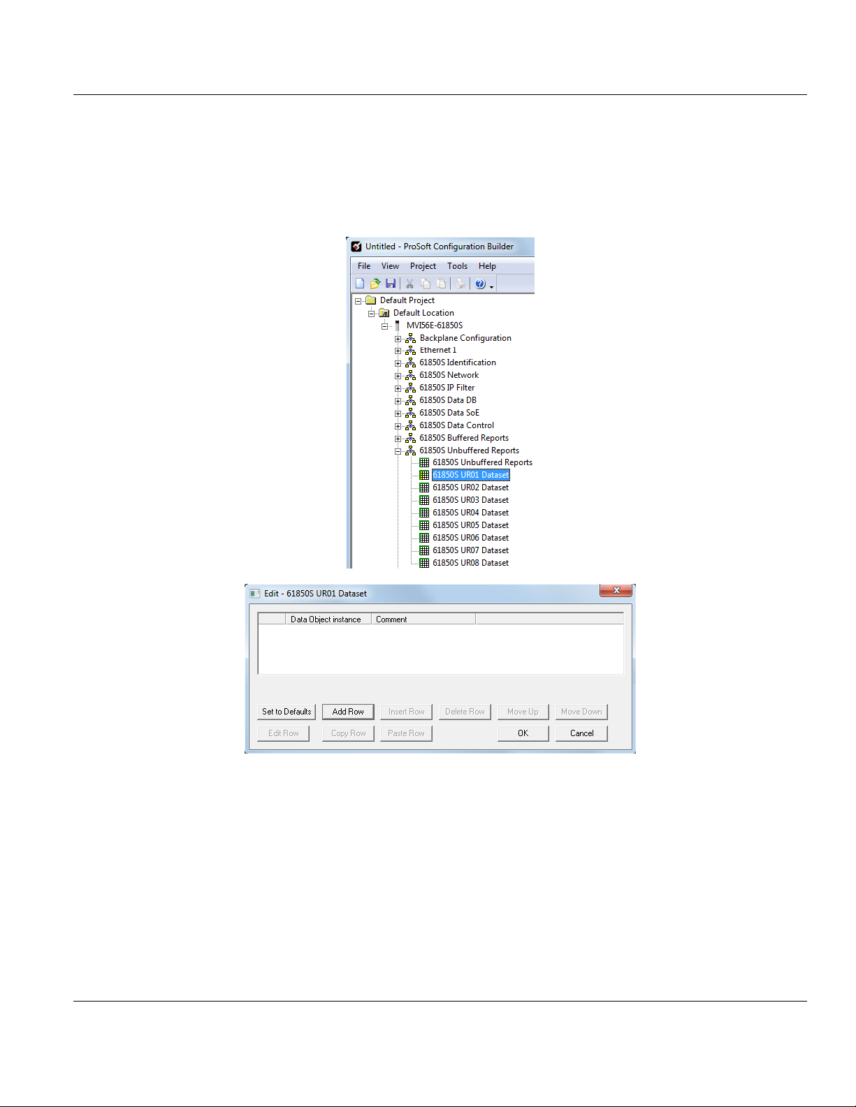
3.10 61850S Unbuffered Reports ................................................................................... 38
3.10.1 61850S UR0x Dataset ............................................................................................. 40
3.11 Downloading the Project to the Module .................................................................. 42
3.11.1 Connecting Your PC to the Module's Ethernet Port ................................................ 44
4 RSLogix 5000 Configuration 49
4.1 MVI56E-61850S User-Defined Data Types ............................................................ 49
4.2 MVI56E-61850S Controller Tags ............................................................................ 49
4.2.1 61850S Controller Tag Overview ............................................................................ 49
4.2.2 MVI56E61850S.DATA ............................................................................................. 50
4.2.3 MVI56E61850S.COMMAND ................................................................................... 51
4.2.4 MVI56E61850S.STATUS Tag ................................................................................. 52
4.2.5 MVI56E61850S.UTIL Tag ....................................................................................... 52
ProSoft Technology, Inc. Page 5 of 81
September 4, 2014
Page 6

Contents MVI56E-61850S ♦ ControlLogix Platform
User Manual IEC 61850 Server Communication Module
5 Examples 53
5.1 Data DB Example ................................................................................................... 53
5.2 SoE Example .......................................................................................................... 58
5.3 Control Example ..................................................................................................... 62
6 Diagnostics and Troubleshooting 65
6.1 Ethernet LED Indicators .......................................................................................... 65
6.1.1 Scrolling LED Status Indicators .............................................................................. 66
6.1.2 Non-Scrolling LED Status Indicators ...................................................................... 67
6.2 Clearing a Fault Condition ...................................................................................... 67
6.3 Troubleshooting ...................................................................................................... 68
6.4 Using the Diagnostics Menu in ProSoft Configuration Builder ............................... 69
6.4.1 Monitoring Module Information ............................................................................... 72
6.4.2 Monitoring Backplane Information .......................................................................... 73
6.4.3 Monitoring Base Configuration Information ............................................................ 74
6.4.4 Monitoring Data Mappings Information ................................................................... 75
6.4.5 Monitoring Backplane Information .......................................................................... 76
6.4.6 Monitoring Flat Database Information .................................................................... 77
6.5 Connect to the Module’s Web Page ....................................................................... 78
7 Support, Service & Warranty 79
7.1 Contacting Technical Support ................................................................................. 79
7.2 Warranty Information .............................................................................................. 80
Index 81
Page 6 of 81 ProSoft Technology, Inc.
September 4, 2014
Page 7

MVI56E-61850S ♦ ControlLogix Platform Contents
In This Chapter
System Requirements............................................................................. 8
Package Contents .................................................................................. 9
Setting Jumpers ...................................................................................... 9
Installing the Module in the Rack ...........................................................10
Connecting Your PC to the ControlLogix Processor ..............................12
Downloading the Sample Program to the Processor .............................13
IEC 61850 Server Communication Module User Manual
1 Start Here
To get the most benefit from this User Manual, you should have the following skills:
Rockwell Automation® RSLogix™ software: launch the program, configure ladder
logic, and transfer the ladder logic to the processor
Microsoft Windows®: install and launch programs, execute menu commands, navigate
dialog boxes, and enter data
Hardware installation and wiring: install the module, and safely connect IEC 61850
and ControlLogix devices to a power source and to the MVI56E-61850S module’s
application port(s)
ProSoft Technology, Inc. Page 7 of 81
September 4, 2014
Page 8
Contents MVI56E-61850S ♦ ControlLogix Platform
User Manual IEC 61850 Server Communication Module
1.1 System Requirements
The MVI56E-61850S module requires the following minimum hardware and software
components:
Rockwell Automation® ControlLogix® processor (firmware version 10 or higher) with
compatible limited voltage power supply and one free slot in the rack for the MVI56E61850S module. The module requires 800 mA of available 5 VDC and 3 mA of available
24 VDC power.
Rockwell Automation RSLogix™ 5000 programming software
o Version 16 or higher required for Add-On Instruction
Rockwell Automation RSLinx® communication software version 2.51 or higher
ProSoft Configuration Builder (PCB) (included)
ProSoft Discovery Service (PDS) (included in PCB)
Pentium® II 450 MHz minimum. Pentium III 733 MHz (or better) recommended
Supported operating systems:
o Microsoft Windows
o Microsoft Windows XP Professional with Service Pack 1 or 2
o Microsoft Windows 7 Professional (32 or 64-bit)
o Microsoft Windows 2000 Professional with Service Pack 1, 2, or 3
o Microsoft Windows Server 2003
128 MB of RAM minimum, 256 MB of RAM recommended
100 MB of free hard disk space (or more based on application requirements)
256-color VGA graphics adapter, 800 x 600 minimum resolution (True Color 1024 768
recommended)
DVD drive
®
Vista
Note: The Hardware and Operating System requirements in this list are the minimum recommended to install
and run software provided by ProSoft Technology®. Other third party applications may have different minimum
requirements. Refer to the documentation for any third party applications for system requirements.
Note: You can install the module in a local or remote rack. For remote rack installation, the module requires
EtherNet/IP or ControlNet communication with the processor.
Page 8 of 81 ProSoft Technology, Inc.
September 4, 2014
Page 9
MVI56E-61850S ♦ ControlLogix Platform Contents
Qty.
Part Name
Part Number
Part Description
1
MVI56E-61850S Module
MVI56E-61850S
IEC 61850 Server Communication Module
1
Ethernet Cable
RL-CBL025
Straight-through Ethernet cable
1
ProSoft Solutions DVD
DVD-001
Contains sample programs, utilities, and documentation.
Files can also be found at
http://www.prosoft-technology.com
IEC 61850 Server Communication Module User Manual
1.2 Package Contents
The following components are included with your MVI56E-61850S module, and are all
required for installation and configuration.
Important: Before beginning the installation, please verify that all of the following items are present.
If any of these components are missing, please contact ProSoft Technology Technical
Support for replacement parts. If the DVD is not present, please visit
http://www.prosoft-technology.com for the latest files.
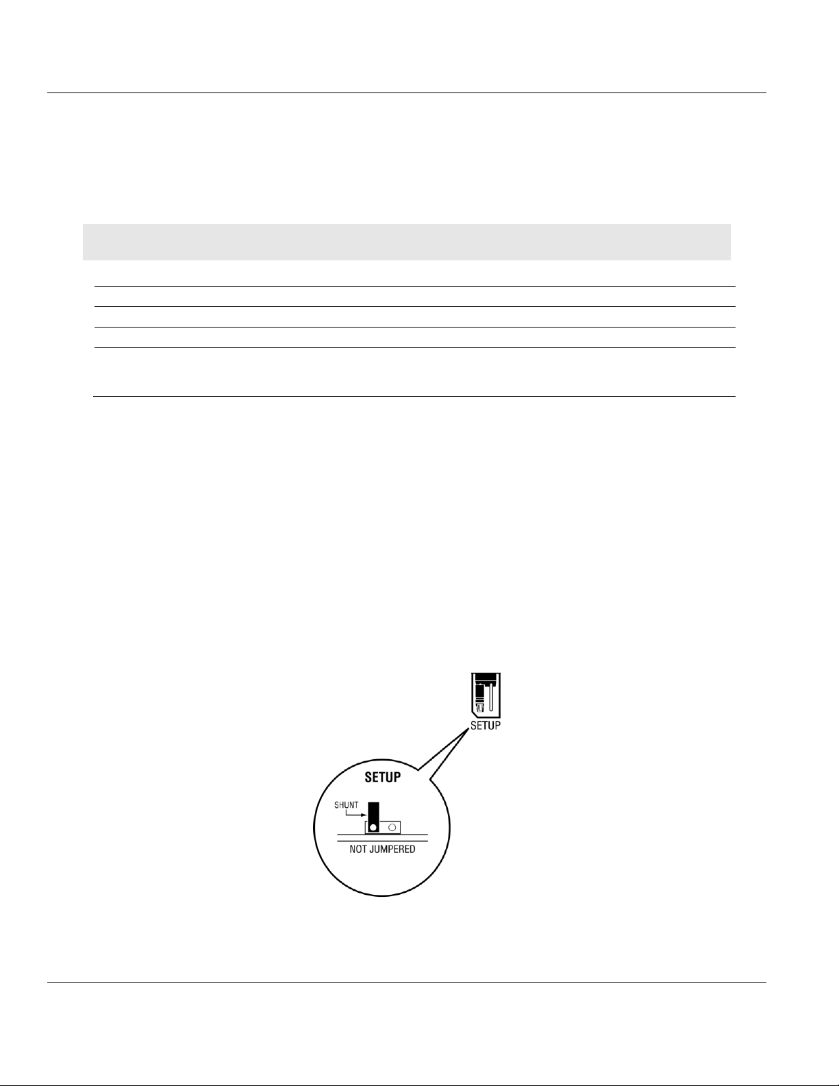
1.3 Setting Jumpers
The Setup Jumper acts as "write protection" for the module’s flash memory. In "write
protected" mode, the Setup pins are not connected, and the module’s firmware cannot be
overwritten. The module is shipped with the Setup jumper OFF. Do not jumper the Setup
pins together unless you are directed to do so by ProSoft Technical Support (or to update
the module firmware).
The following illustration shows the MVI56E-61850S jumper configuration with the Setup
Jumper OFF.
ProSoft Technology, Inc. Page 9 of 81
September 4, 2014
Page 10
Contents MVI56E-61850S ♦ ControlLogix Platform
User Manual IEC 61850 Server Communication Module
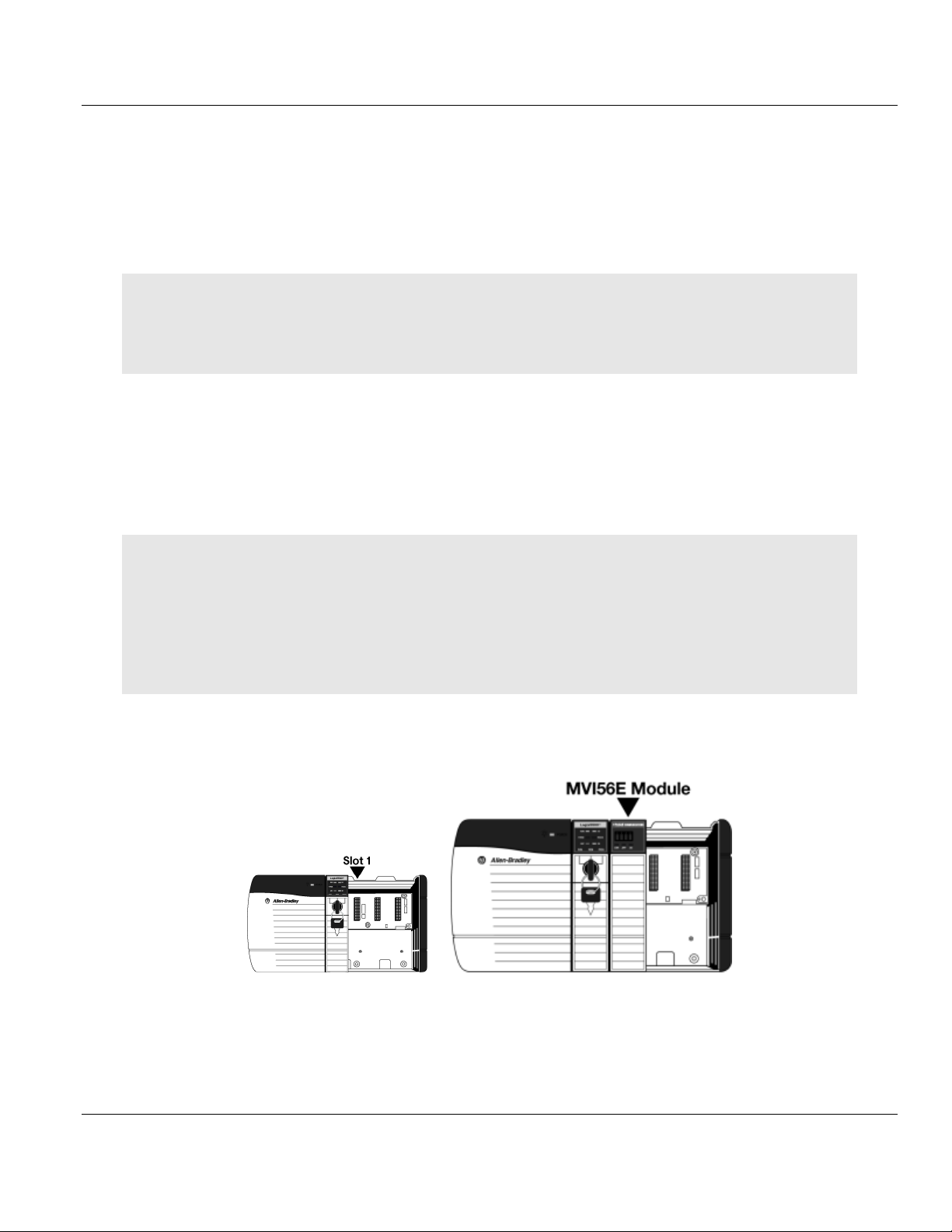
1.4 Installing the Module in the Rack
Make sure your ControlLogix processor and power supply are installed and configured,
before installing the MVI56E-61850S module. Refer to your Rockwell Automation product
documentation for installation instructions.
Warning: You must follow all safety instructions when installing this or any other electronic devices. Failure to
follow safety procedures could result in damage to hardware or data, or even serious injury or death to
personnel. Refer to the documentation for each device you plan to connect to verify that suitable safety
procedures are in place before installing or servicing the device.
After you have checked the placement of the jumpers, insert the MVI56E-61850S into the
ControlLogix chassis. Use the same technique recommended by Rockwell Automation to
remove and install ControlLogix modules.
You can install or remove ControlLogix system components while chassis power is applied
and the system is operating. However, please note the following warning.
Warning: When you insert or remove the module while backplane power is on, an electrical arc can occur. An
electrical arc can cause personal injury or property damage by sending an erroneous signal to the system’s
actuators. This can cause unintended machine motion or loss of process control. Electrical arcs may also cause
an explosion when they happen in a hazardous environment. Verify that power is removed or the area is nonhazardous before proceeding.
Repeated electrical arcing causes excessive wear to contacts on both the module and its mating connector.
Worn contacts may create electrical resistance that can affect module operation.
1 Align the module with the top and bottom guides, and then slide it into the rack until the
module is firmly against the backplane connector.
2 With a firm, steady push, snap the module into place.
3 Check that the holding clips on the top and bottom of the module are securely in the
locking holes of the rack.
Page 10 of 81 ProSoft Technology, Inc.
September 4, 2014
Page 11

MVI56E-61850S ♦ ControlLogix Platform Contents
IEC 61850 Server Communication Module User Manual
4 Make a note of the slot location. You must identify the slot in which the module is
installed in order for the sample program to work correctly. Slot numbers are identified
on the green circuit board (backplane) of the ControlLogix rack.
5 Turn power ON.
Note: If you insert the module improperly, the system may stop working or may behave unpredictably.
ProSoft Technology, Inc. Page 11 of 81
September 4, 2014
Page 12
Contents MVI56E-61850S ♦ ControlLogix Platform
User Manual IEC 61850 Server Communication Module
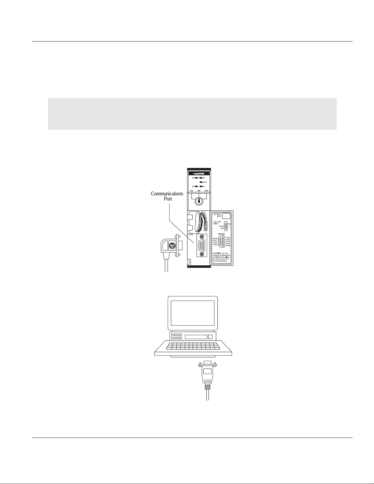
1.5 Connecting Your PC to the ControlLogix Processor
There are several ways to establish communication between your PC and the ControlLogix
processor. The following steps show how to establish communication through the serial
interface.
Note: It is not mandatory that you use the processor's serial interface. You may access the processor through
whatever network interface is available on your system. Refer to your Rockwell Automation documentation for
information on other connection methods.
1 Connect the right-angle connector end of the cable to your controller at the
communications port.
2 Connect the straight connector end of the cable to the serial port on your computer.
Page 12 of 81 ProSoft Technology, Inc.
September 4, 2014
Page 13
MVI56E-61850S ♦ ControlLogix Platform Contents
IEC 61850 Server Communication Module User Manual
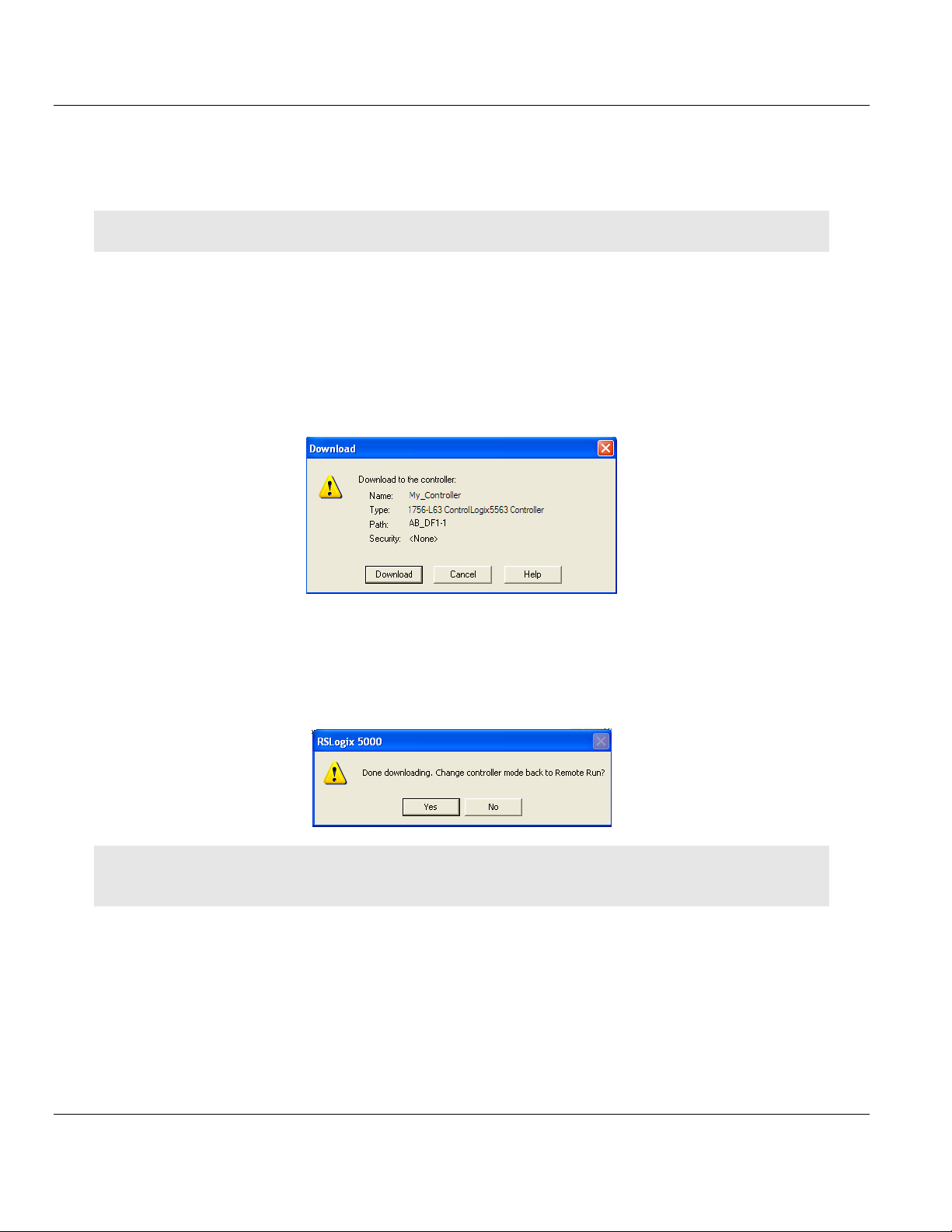
1.6 Downloading the Sample Program to the Processor
Note: The key switch on the front of the ControlLogix processor must be in the REM or PROG position.
1 If you are not already online with the processor, in RSLogix 5000 open the
Communications menu, and then choose DOWNLOAD. RSLogix 5000 will establish
communication with the processor. You do not have to download through the
processor's serial port, as shown here. You may download through any available
network connection.
2 When communication is established, RSLogix 5000 will open a confirmation dialog box.
Click the DOWNLOAD button to transfer the sample program to the processor.
3 RSLogix 5000 will compile the program and transfer it to the processor. This process
may take a few minutes.
4 When the download is complete, RSLogix 5000 will open another confirmation dialog
box. If the key switch is in the REM position, click OK to switch the processor from
PROGRAM mode to RUN mode.
Note: If you receive an error message during these steps, refer to your RSLogix documentation to interpret and
correct the error.
ProSoft Technology, Inc. Page 13 of 81
September 4, 2014
Page 14
Contents MVI56E-61850S ♦ ControlLogix Platform
User Manual IEC 61850 Server Communication Module
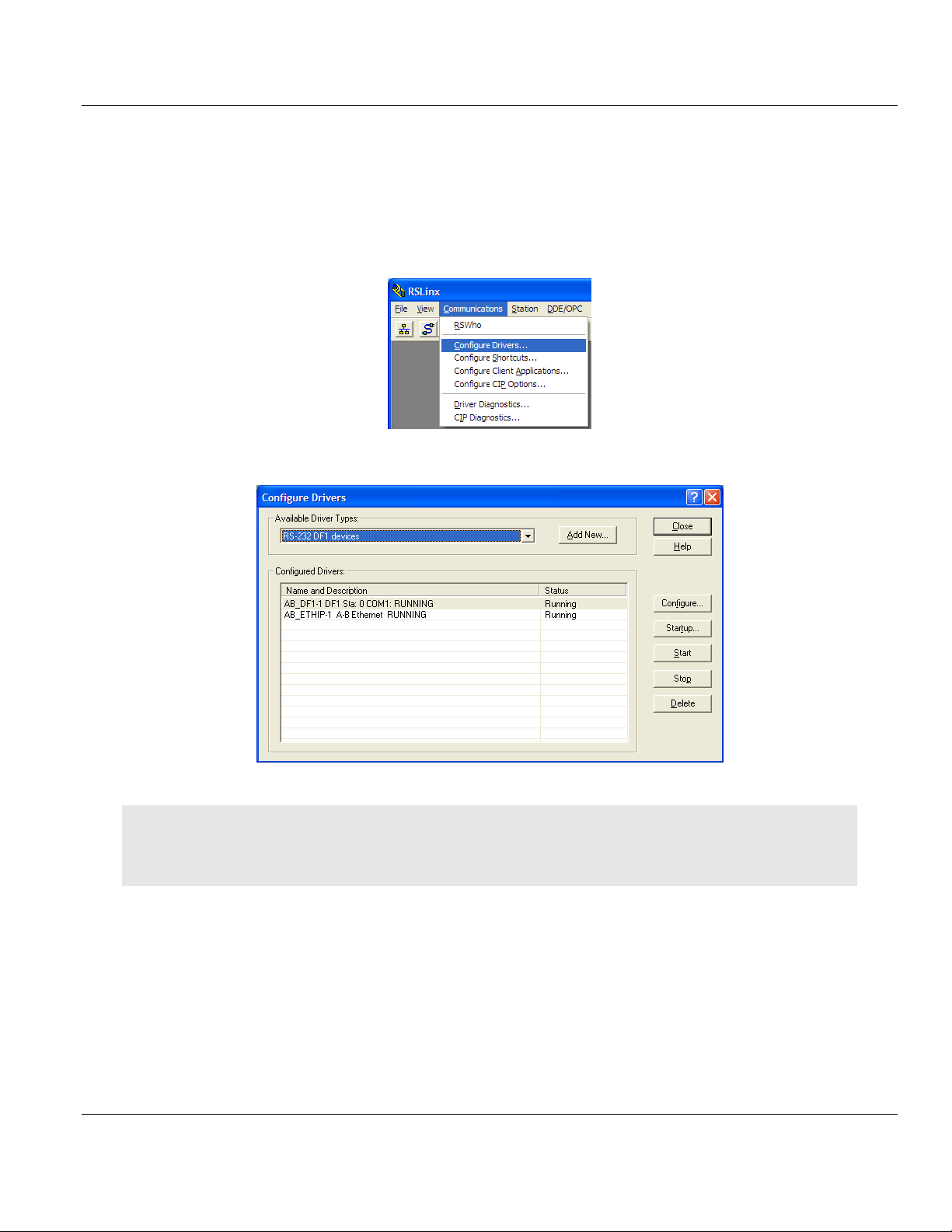
1.6.1 Configuring the RSLinx Driver for the PC COM Port
When trying to connect serially, if RSLogix is unable to establish communication with the
processor, follow these steps.
1 Open RSLinx.
2 Open the COMMUNICATIONS menu, and click CONFIGURE DRIVERS.
This action opens the Configure Drivers dialog box.
Note: If the list of configured drivers is blank, you must first choose and configure a driver from the Available
Driver Types list. The recommended driver type to choose for serial communication with the processor is RS-232
DF1 Devices.
Page 14 of 81 ProSoft Technology, Inc.
September 4, 2014
Page 15
MVI56E-61850S ♦ ControlLogix Platform Contents
IEC 61850 Server Communication Module User Manual
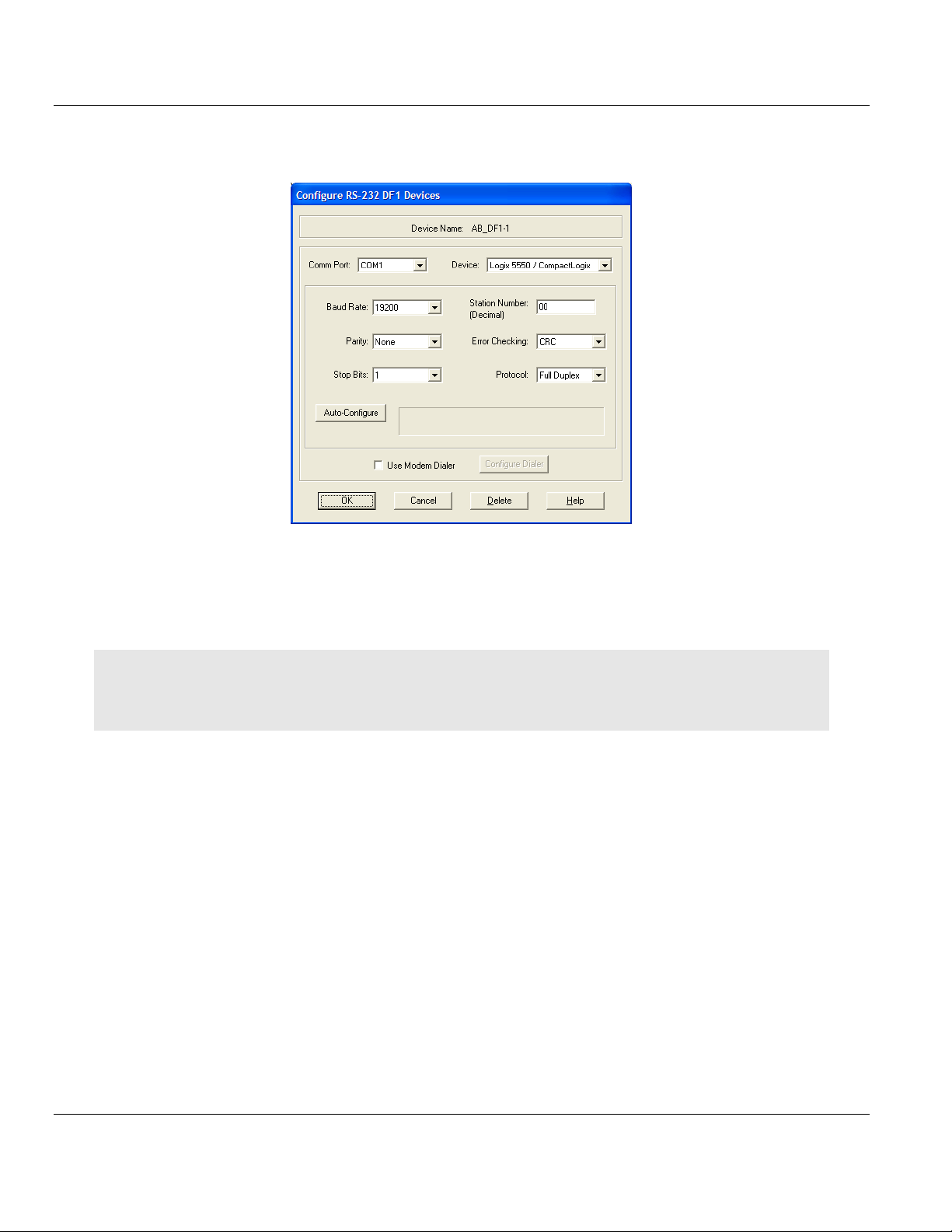
3 Click to select the driver, and then click CONFIGURE. This action opens the Configure
RS-232 DF1 Devices dialog box.
4 Click the AUTO-CONFIGURE button. RSLinx will attempt to configure your serial port to
work with the selected driver.
5 When you see the message Auto Configuration Successful, click the OK button to
dismiss the dialog box.
Note: If the auto-configuration procedure fails, verify that the cables are connected correctly between the
processor and the serial port on your computer, and then try again. If you are still unable to auto-configure the
port, refer to your RSLinx documentation for further troubleshooting steps.
ProSoft Technology, Inc. Page 15 of 81
September 4, 2014
Page 16

Contents MVI56E-61850S ♦ ControlLogix Platform
User Manual IEC 61850 Server Communication Module
Page 16 of 81 ProSoft Technology, Inc.
September 4, 2014
Page 17

MVI56E-61850S ♦ ControlLogix Platform Contents
In This Chapter
Installing ProSoft Configuration Builder .................................................17
Setting Up the Project ............................................................................18
IEC 61850 Server Communication Module User Manual
2 Setting Up ProSoft Configuration Builder
ProSoft Configuration Builder (PCB) software provides a convenient way to configure,
monitor, and troubleshoot your MVI56E-61850S module.
2.1 Installing ProSoft Configuration Builder
The ProSoft Configuration Builder (PCB) software is used to configure the module. You can
find the latest version of the ProSoft Configuration Builder (PCB) on our web site:
http://www.prosoft-technology.com, or you can install it from the ProSoft Solutions DVD. The
installation filename contains the PCB version number. For example,
PCB_4.1.0.4.0206.EXE.
If you are installing PCB from the ProSoft website:
1 Open a browser window and navigate to http://www.prosoft-technology.com/pcb.
2 Click the download link for ProSoft Configuration Builder, and save the file to your
Windows desktop.
3 After the download completes, double-click the file to install. If you are using Windows 7,
right-click on the PCB installation file and click RUN AS ADMINISTRATOR. Follow the
instructions that appear on the screen.
4 If you want to find additional software specific to your MVI56E-61850S, enter the model
number into the website search box and press the Enter key.
If you are installing PCB from the ProSoft Solutions DVD:
1 Insert the ProSoft Solutions DVD into your computer's DVD drive and wait for the
ProSoft Installation program to start.
2 If the ProSoft Installation program does not start, open the Windows file Explorer,
navigate to the DVD, and double-click on the ProSoft_DVD.exe file.
3 Navigate to the MVI56E-61850S selection using the PLATFORM and PRODUCT selections.
4 Click PROSOFT CONFIGURATION BUILDER.
5 Follow the instructions that appear on the screen.
ProSoft Technology, Inc. Page 17 of 81
September 4, 2014
Page 18
Contents MVI56E-61850S ♦ ControlLogix Platform
User Manual IEC 61850 Server Communication Module
2.2 Setting Up the Project
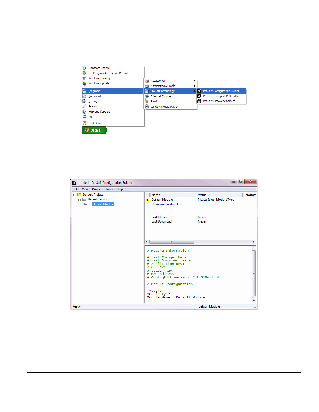
To begin, start PROSOFT CONFIGURATION BUILDER (PCB).
If you have used other Windows configuration tools before, you will find the screen layout
familiar. PCB’s window consists of a tree view on the left, and an information pane and a
configuration pane on the right side of the window. When you first start PCB, the tree view
consists of folders for Default Project and Default Location, with a Default Module in the
Default Location folder. The following illustration shows the PCB window with a new project.
Page 18 of 81 ProSoft Technology, Inc.
September 4, 2014
Page 19
MVI56E-61850S ♦ ControlLogix Platform Contents
IEC 61850 Server Communication Module User Manual
Your first task is to add the MVI56E-61850S module to the project.
1 Use the mouse to select DEFAULT MODULE in the tree view, and then click the right
mouse button to open a shortcut menu.
2 On the shortcut menu, select CHOOSE MODULE TYPE. This action opens the Choose
Module Type dialog box.
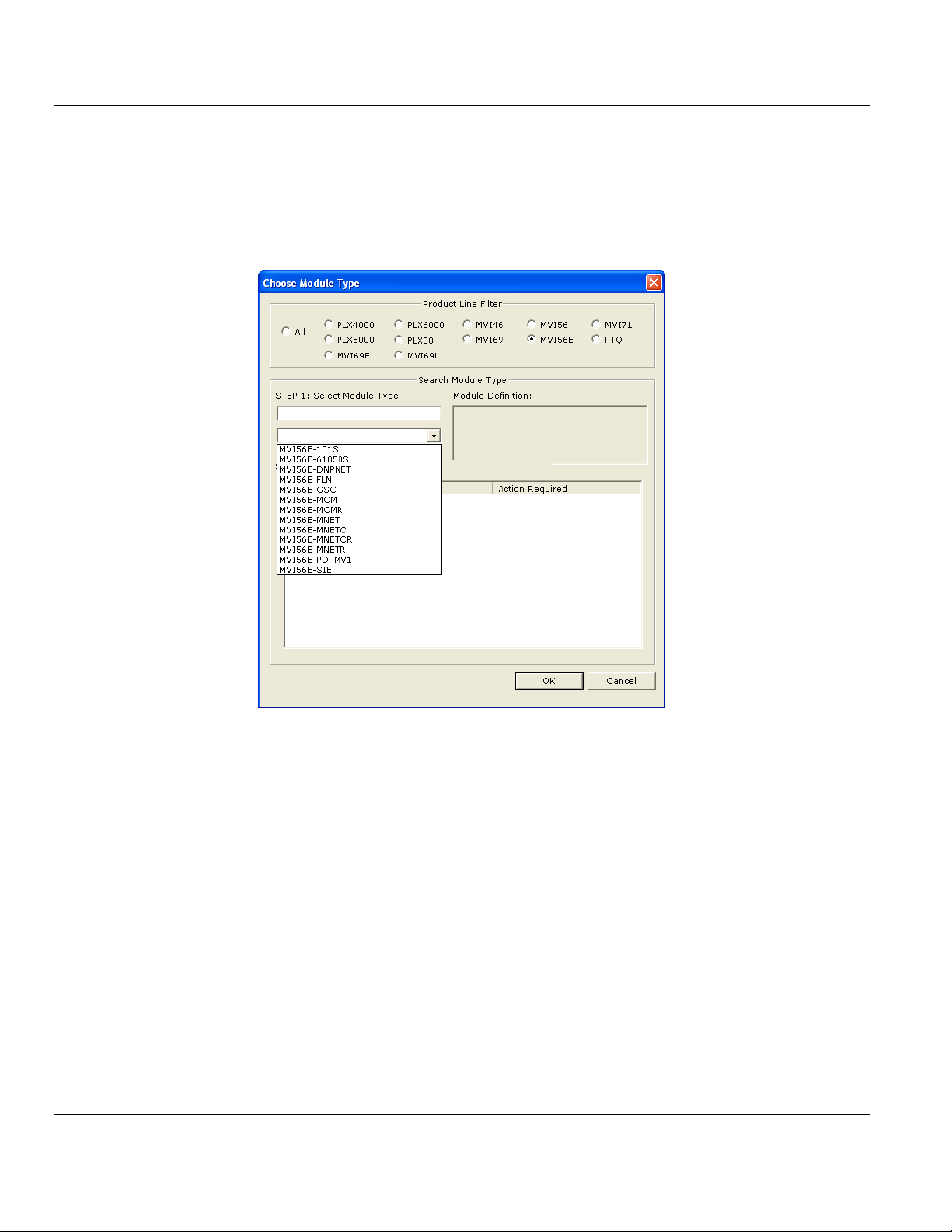
3 In the Product Line Filter area of the dialog box, select MVI56E. In the Select Module
Type dropdown list, select MVI56E-61850S, and then click OK to save your settings and
return to the ProSoft Configuration Builder window.
ProSoft Technology, Inc. Page 19 of 81
September 4, 2014
Page 20

Contents MVI56E-61850S ♦ ControlLogix Platform
User Manual IEC 61850 Server Communication Module
Page 20 of 81 ProSoft Technology, Inc.
September 4, 2014
Page 21

MVI56E-61850S ♦ ControlLogix Platform Contents
In This Chapter
Backplane Configuration ........................................................................22
Ethernet1 ...............................................................................................23
61850S Identification .............................................................................24
61850S Network ....................................................................................25
61850S IP Filter .....................................................................................26
61850S Data DB Configuration ..............................................................28
61850S Data SoE ..................................................................................30
61850S Data Control .............................................................................32
61850S Buffered Reports ......................................................................34
61850S Unbuffered Reports ..................................................................38
Downloading the Project to the Module .................................................42
IEC 61850 Server Communication Module User Manual
3 MVI56E-61850S Configuration
This chapter covers the MVI56E-61850S configuration within ProSoft Configuration Builder.
ProSoft Technology, Inc. Page 21 of 81
September 4, 2014
Page 22
Contents MVI56E-61850S ♦ ControlLogix Platform
Name
Range
Description
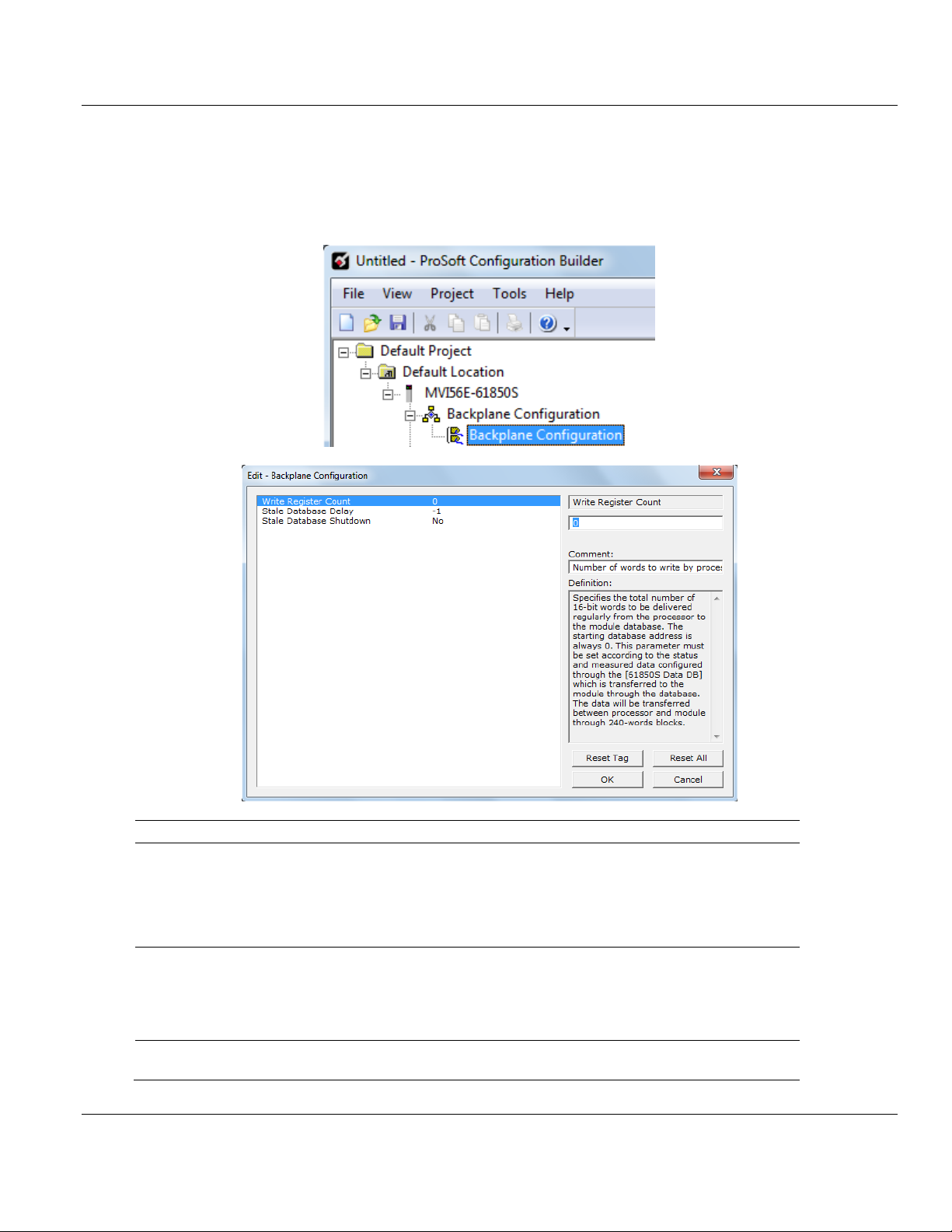
Write Register Count
0 to 4000
For Data DB objects. Number of registers to write
from processor to module. The starting register is
0. This parameter must be set according to the
status and measured data configured through the
[61850S Data DB] section, which is transferred to
the module through the database.
Stale Database Delay
1 to 300000
-1 = Ignore
0 = No delay (issue a
stale-database event
upon detecting failure)
Minimum duration (ms) of backplane I/O failure that
causes the database to be marked stale.
Stale Database Shutdown
Yes/No
Determines whether to shut down the 61850
protocol upon a stale-database event.
User Manual IEC 61850 Server Communication Module
3.1 Backplane Configuration
This section of the configuration describes the database setup and module-level
parameters. Double-click the BACKPLANE CONFIGURATION icon to edit the parameters.
Page 22 of 81 ProSoft Technology, Inc.
September 4, 2014
Page 23
MVI56E-61850S ♦ ControlLogix Platform Contents
Name
Description
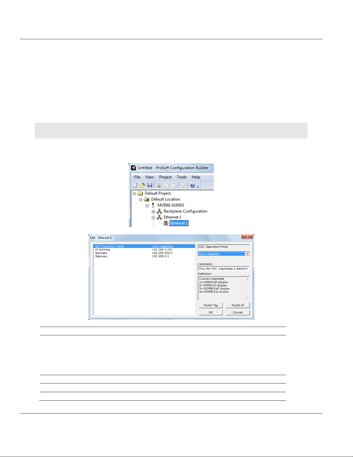
NIC Operation Mode
Mode in which the NIC negotiates a datalink
0 = Auto-negotiate
1 = 10MB/half-duplex
2 = 10MB/full-duplex
3 = 100MB/half-duplex
4 = 100MB/full-duplex
IP Address
Default private class 3 address
Netmask
Default class 3 network mask
Gateway
Default gateway to another network
IEC 61850 Server Communication Module User Manual
3.2 Ethernet1
In this step, you assign an IP address for the MVI56E-61850S module. This becomes the
permanent IP address for the module after you download the configuration to the module.
The module’s default IP address is 192.168.0.250. Determine the network settings for your
module, with the help of your network administrator if necessary.
o IP address (fixed IP required) _____ . _____ . _____ . _____
o Subnet mask _____ . _____ . _____ . _____
o Gateway address _____ . _____ . _____ . _____
Note: The gateway address is optional, and is not required for networks that do not use a default gateway.
Double-click the ETHERNET1 icon to edit the parameters.
ProSoft Technology, Inc. Page 23 of 81
September 4, 2014
Page 24
Contents MVI56E-61850S ♦ ControlLogix Platform
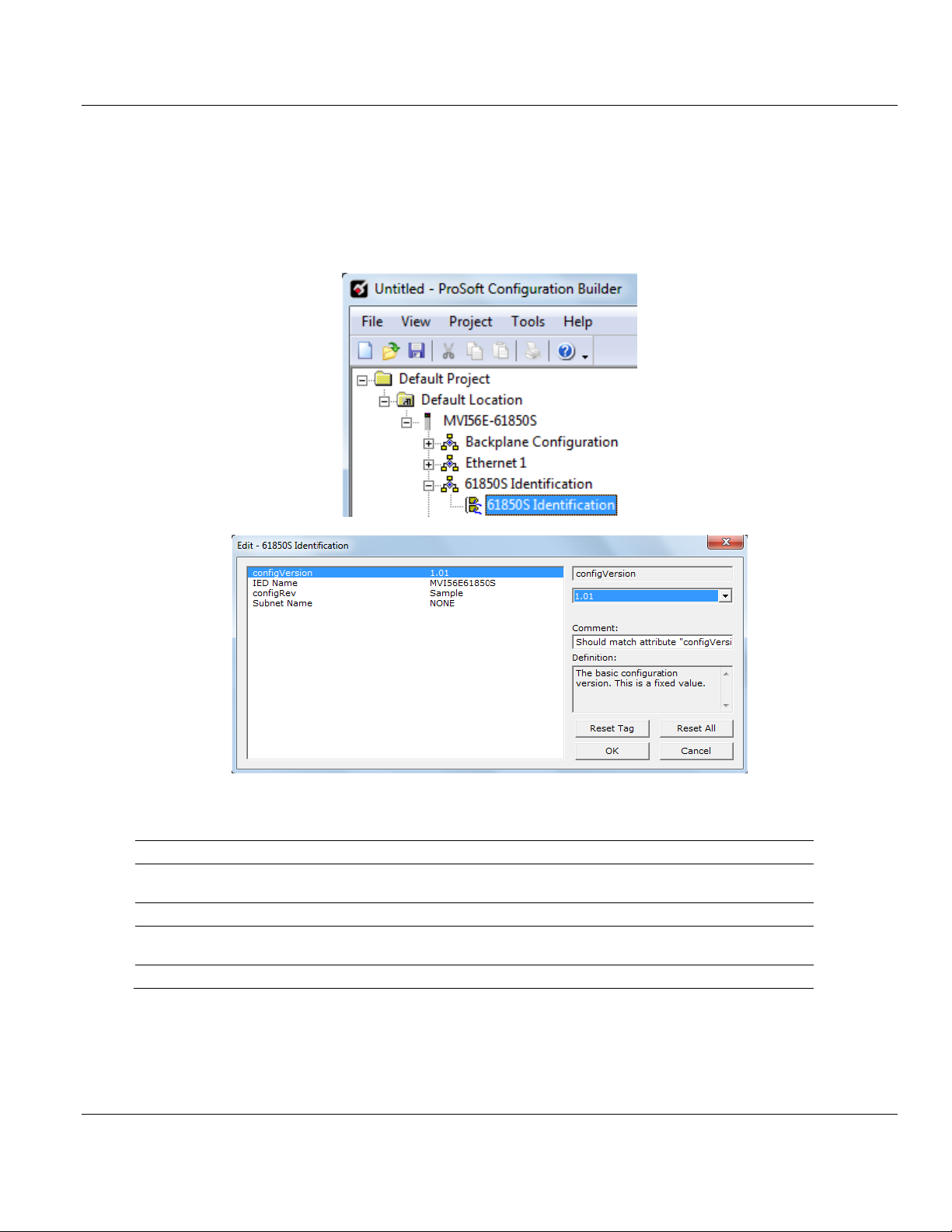
Name
Description
configVersion
Version of the configuration. It should match attribute "configVersion" of CID's "IED"
element
IED Name
Name of this IED, which must be unique over all IEDs
configRev
Uniquely identifies the configuration the IED. Mapped 61850 to data attribute
LLN0$DC$NamPlt$configRev
Subnet Name
Name of the station "subnetwork" on which this IED resides; meaningful only for SCD files
User Manual IEC 61850 Server Communication Module
3.3 61850S Identification
This section allows you to assign unique IED identification parameters to the module.
Double-click the 61850S IDENTIFICATION icon to edit the parameters.
Page 24 of 81 ProSoft Technology, Inc.
September 4, 2014
Page 25
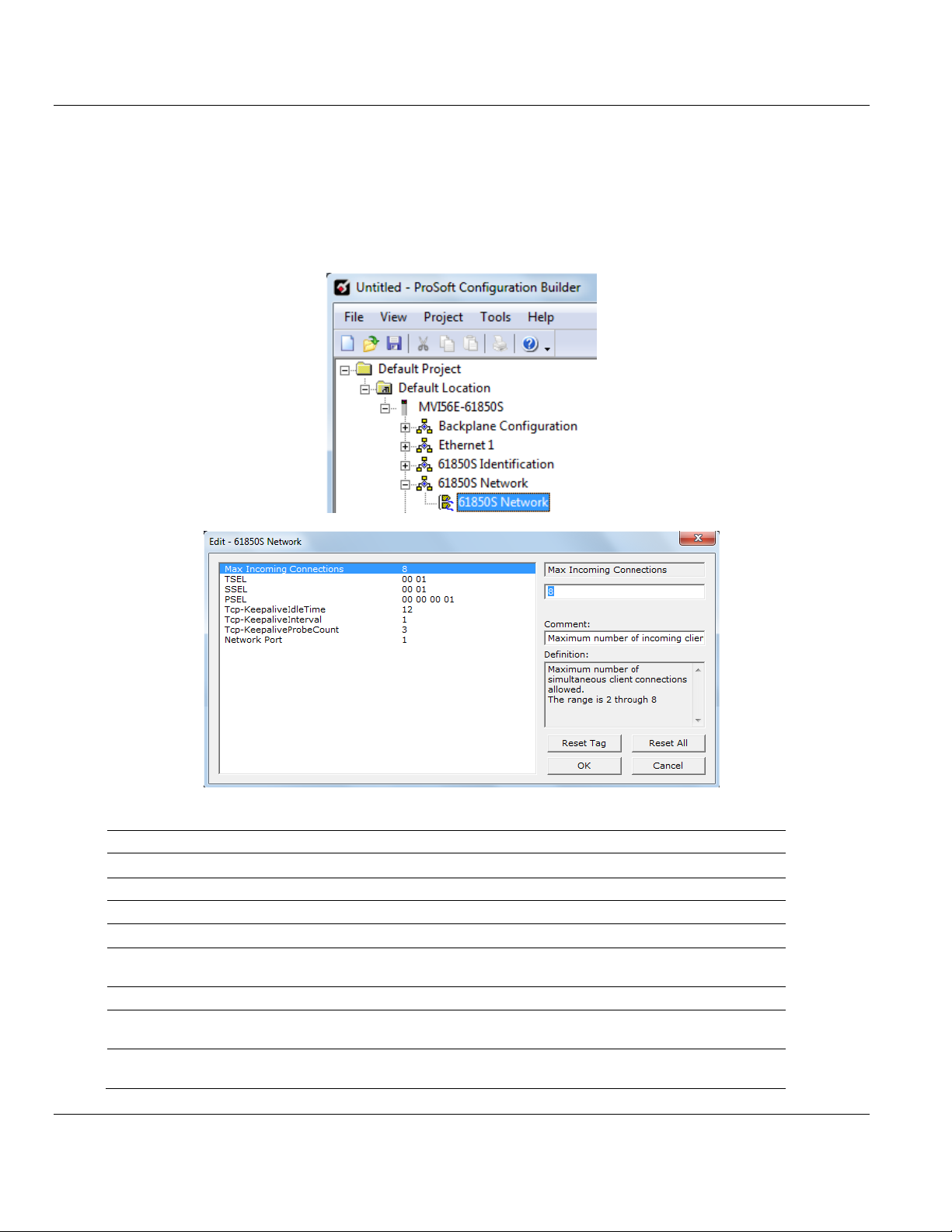
MVI56E-61850S ♦ ControlLogix Platform Contents
Name
Range
Description
Max Incoming Connections
2 to 8
Maximum number of simultaneous client connections allowed.
TSEL
Transport Selector
SSEL
Session Selector
PSEL
Presentation Selector
Tcp-KeepaliveIdleTime
1 to 60
Maximum TCP-connection idle time before beginning keepalive probes, in seconds.
Tcp-KeepaliveInterval
1 to 60
Interval between failed keep-alive probes, in seconds.
Tcp-KeepaliveProbeCount
1 to 9
Number of consecutive failed keep-alive probes causing
connection to be deemed broken
Network Port
1
This number selects the physical Ethernet interface to be used
for the 61850 protocol. This value cannot be changed.
IEC 61850 Server Communication Module User Manual
3.4 61850S Network
This section allows you to set the parameters on incoming IEC 61850 client connections.
Double-click the 61850S NETWORK icon to edit the parameters.
ProSoft Technology, Inc. Page 25 of 81
September 4, 2014
Page 26

Contents MVI56E-61850S ♦ ControlLogix Platform
Name
Range
Description
Enable IP Filter
Yes/No
Enables control of the remote client access based on its IP
address.
IP Filter Type
Whitelist/Blacklist
Whitelist denies all IPs except those IPs or subnets listed as
allowed in IP Filter List.
Blacklist allows all IPs except those listed as denied in IP Filter List.
User Manual IEC 61850 Server Communication Module
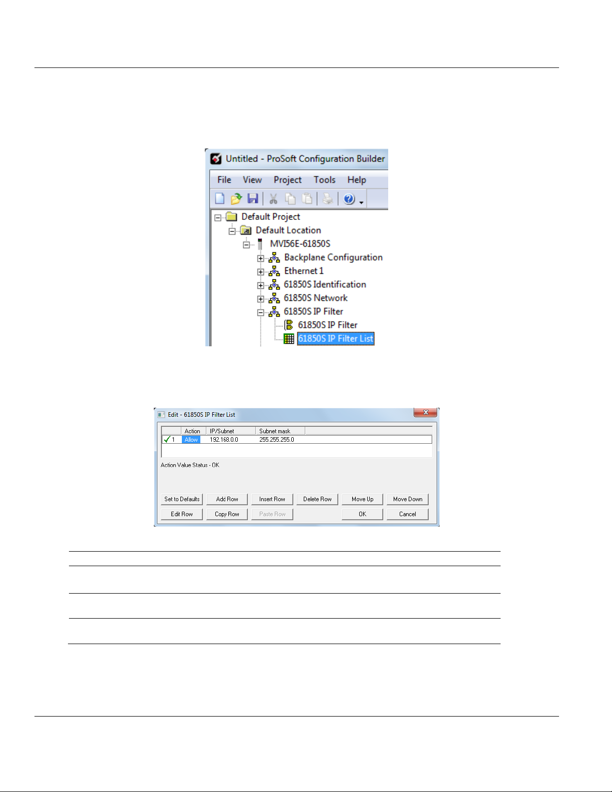
3.5 61850S IP Filter
This section allows you to create a whitelist or blacklist to allow/deny outside IP address
connections.
Double-click the 61850S IP FILTER icon to edit the parameters.
Page 26 of 81 ProSoft Technology, Inc.
September 4, 2014
Page 27
MVI56E-61850S ♦ ControlLogix Platform Contents
Name
Range
Description
Action
Allow/Deny
Select Allow for allowed IP or subnet for Whitelist filter type.
Select Deny for denied IP or subnet for Blacklist filter type.
IP/Subnet
Enter an IPv4 address or subnet in standard dotted notation. The
candidate IP matches this entry if it matches this IP or subnet.
Subnet mask
Enter an IPv4 subnet mask in standard dotted notation. The candidate
IP and the IP/subnet match if they are the same under this mask.
IEC 61850 Server Communication Module User Manual
If the IP Filter is enabled, you will need to configure the IP addresses to be filtered.
1 Double-click the 61850S IP FILTER LIST icon.
2 Click ADD ROW then EDIT ROW to enter the IP address information.
ProSoft Technology, Inc. Page 27 of 81
September 4, 2014
Page 28

Contents MVI56E-61850S ♦ ControlLogix Platform
User Manual IEC 61850 Server Communication Module
3.6 61850S Data DB Configuration
This section allows you to configure DB data objects (DO's) for the MVI56E-61850S. This
data will be updated to the module from the processor.
1 Double-click the 61850S DATA DB icon to open the configuration window.
2 Click ADD ROW then EDIT ROW to edit.
Page 28 of 81 ProSoft Technology, Inc.
September 4, 2014
Page 29

MVI56E-61850S ♦ ControlLogix Platform Contents
Name
Description
Data Object
This value identifies the 61850 data object (DO) instantiated from a 61850 CDC to
which the data point is mapped.
The data object number has to be set within a specific range according to its data type:
BOOL: 100000 to 109999
SINT: 200000 to 209999
INT: 210000 to 219999
DINT: 220000 to 229999
REAL: 300000 to 309999
FLOATDB: 350000 to 359999 (50 points maximum)
Data Type
Type of the data as it resides in the internal database.
BOOL: Boolean / Bit
SINT: (Signed-8 bits) / Byte
INT: (Signed-16 bits) / Word
DINT: (Signed-32 bits) / Double word
REAL: (32-bit floating) / Double word
FLOATDB: (32-bit floating) / Double word deadbanded
DB Value Offset
The offset of the data point value in the internal database. The database addressing
value is interpreted according to the data type as follows:
BOOL: Boolean addressing
SINT: Byte addressing
INT: Word addressing
DINT: Double-word addressing
REAL: Double-word addressing
FLOATDB: Double-word addressing
Specify -1 if the associated status data attribute is not to be mapped.
DB Quality Offset
The offset (in bytes) of the corresponding quality byte in the internal database, which
must reside in the same backplane block (240-word block) as the status value itself.
The database is transferred from the processor to the module in blocks of 240 words.
As the quality information is tightly linked to the actual status value data, the module
must receive them both simultaneously in order for them both to be correctly
processed. If the status point has no associated quality information in the processor,
therefore no quality byte is to be delivered, specify as -1.
Min
*Only applicable for FLOATDB type.
The minimum valid value of the instantaneous analog value, delivered from the
processor to the 61850 data attribute. If the received status value from processor is less
than configured minimum value, the module will set the Out of Range quality flag.
Max
*Only applicable for FLOATDB type.
The maximum valid value of the instantaneous analog value, delivered from the
processor to the 61850 data attribute. If the received status value from processor is
greater than configured maximum value, the module will set the Out of Range quality
flag.
Deadband Width
*Only applicable for FLOATDB type.
The deadband width, as parts per 100,000 of the extent "Max"-"Min" of the valid range.
The actual width, in the engineering units of the analog input is set by: DbWdth *
[(Max-Min)/100000]
Comment
Comments cannot be edited
IEC 61850 Server Communication Module User Manual
ProSoft Technology, Inc. Page 29 of 81
September 4, 2014
Page 30

Contents MVI56E-61850S ♦ ControlLogix Platform
User Manual IEC 61850 Server Communication Module
3.7 61850S Data SoE
This section allows you to configure SoE data objects (DO's) for the MVI56E-61850S. This
data will be updated to the module from the processor.
1 Double-click the 61850S DATA SOE icon to open the configuration window.
2 Click ADD ROW then EDIT ROW to edit.
Page 30 of 81 ProSoft Technology, Inc.
September 4, 2014
Page 31

MVI56E-61850S ♦ ControlLogix Platform Contents
Name
Description
Data Object
This value identifies the 61850 data object (DO) instantiated from a 61850 CDC to
which the data point is mapped. The data object number has to be set within a specific
range according to its data type:
BOOL: 400000 to 409999
SINT: 500000 to 509999
INT: 510000 to 519999
DINT: 520000 to 529999
REAL: 600000 to 609999
FLOATDB: 650000 to 659999 (50 points maximum)
Data Type
Type of the data as it resides in the internal database.
BOOL: Boolean / Bit
SINT: (Signed-8 bits) / Byte
INT: (Signed-16 bits) / Word
DINT: (Signed-32 bits) / Double word
REAL: (32-bit floating) / Double word
FLOATDB: (32-bit floating) / Double word deadbanded
Point ID
Unique identifier for the SoE point in the processor. It is a 16-bit value.
Min
*Only applicable for FLOATDB type.
The minimum valid value of the instantaneous analog value, delivered from the
processor to the 61850 data attribute. If the received status value from processor is less
than configured minimum value, the module will set the Out of Range quality flag.
Max
*Only applicable for FLOATDB type.
The maximum valid value of the instantaneous analog value, delivered from the
processor to the 61850 data attribute. If the received status value from processor is
greater than configured maximum value, the module will set the Out of Range quality
flag.
Deadband Width
*Only applicable for FLOATDB type.
The deadband width, as parts per 100,000 of the extent "Max"-"Min" of the valid range.
The actual width, in the engineering units of the analog input is set by: DbWdth *
[(Max-Min)/100000]
Comment
Comments cannot be edited
IEC 61850 Server Communication Module User Manual
ProSoft Technology, Inc. Page 31 of 81
September 4, 2014
Page 32
Contents MVI56E-61850S ♦ ControlLogix Platform
User Manual IEC 61850 Server Communication Module
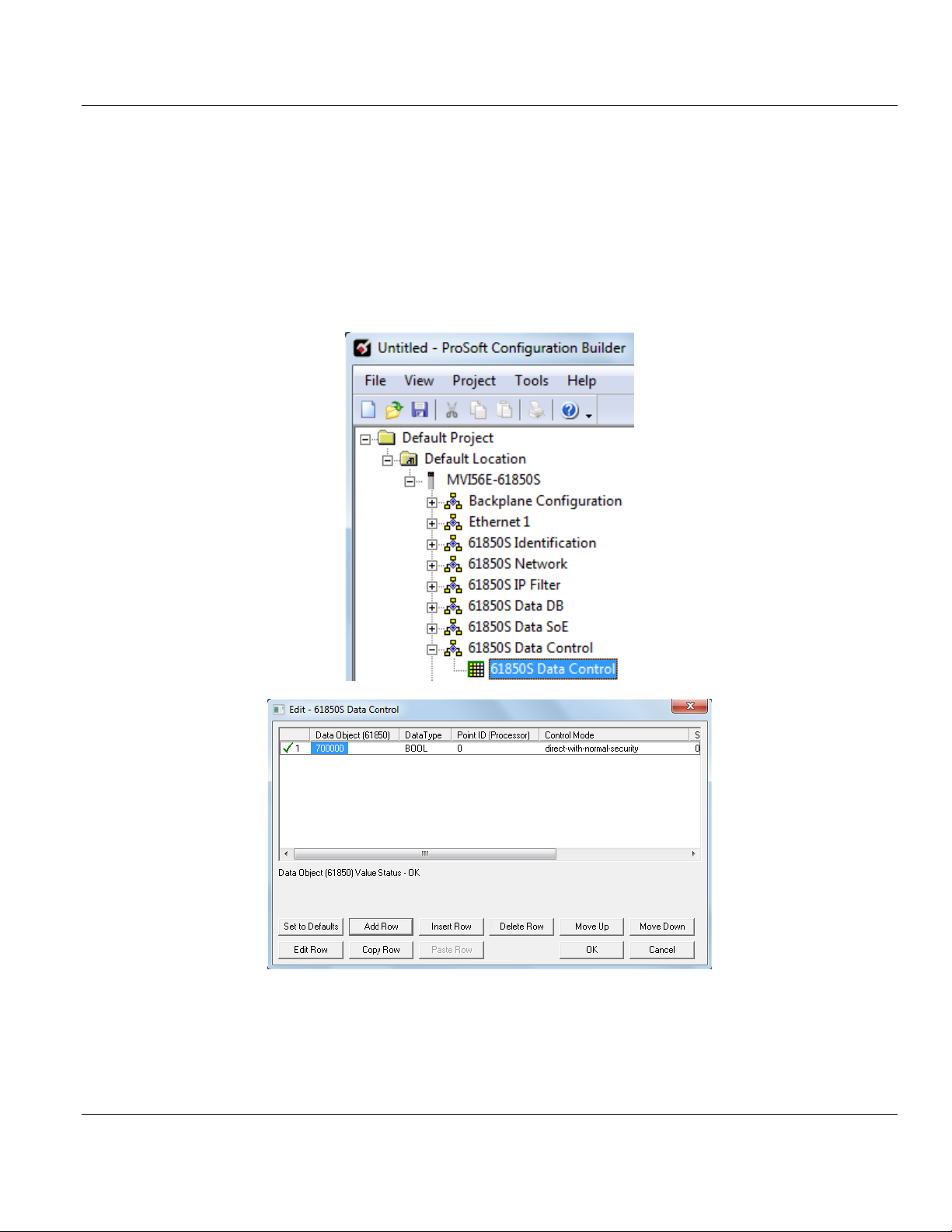
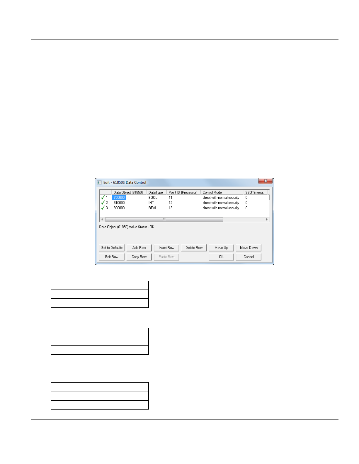
3.8 61850S Data Control
This section allows you to you to configure Control data objects (DO's) for the MVI56E61850S. Control data originates from an IEC 61850 client. The module passes this data to
the processor where it is acknowledged. This processor-acknowledged data is updated back
to the module for a handshake back to the client.
1 Double-click the 61850S DATA CONTROL icon to open the configuration window.
2 Click ADD ROW then EDIT ROW to edit.
Page 32 of 81 ProSoft Technology, Inc.
September 4, 2014
Page 33
MVI56E-61850S ♦ ControlLogix Platform Contents
Name
Description
Data Object
This value identifies the 61850 data object (DO) instantiated from a 61850 CDC to
which the data point is mapped.
The data object number has to be set within a specific range according to its data
type:
BOOL: 700000 to 709999
SINT: 800000 to 809999
INT: 810000 to 819999
DINT: 820000 to 829999
REAL: 900000 to 909999
Data Type
Type of the data as it resides in the internal database.
BOOL: Boolean / Bit
SINT: (Signed-8 bits) / Byte
INT: (Signed-16 bits) / Word
DINT: (Signed-32 bits) / Double word
REAL: (32-bit floating) / Double word
Point ID
Unique identifier for the Control point in the processor. It is a 16-bit value.
Control Mode
A code that selects the 61850 control mode according to IEC61850 specification:
Direct-with-normal-security
Sbo-with-normal-security, operate-once
Sbo-with-normal-security, operate-many
Direct-with-enhanced-security
Sbo-with-enhanced-security, operate-once
Sbo-with-enhanced-security, operate-many
SBO Timeout
*Only applicable for SBO control mode
The timeout in milliseconds for the control object to remain selected without receiving
an Oper or Cancel request
Comment
Comments cannot be edited
IEC 61850 Server Communication Module User Manual
ProSoft Technology, Inc. Page 33 of 81
September 4, 2014
Page 34
Contents MVI56E-61850S ♦ ControlLogix Platform
User Manual IEC 61850 Server Communication Module
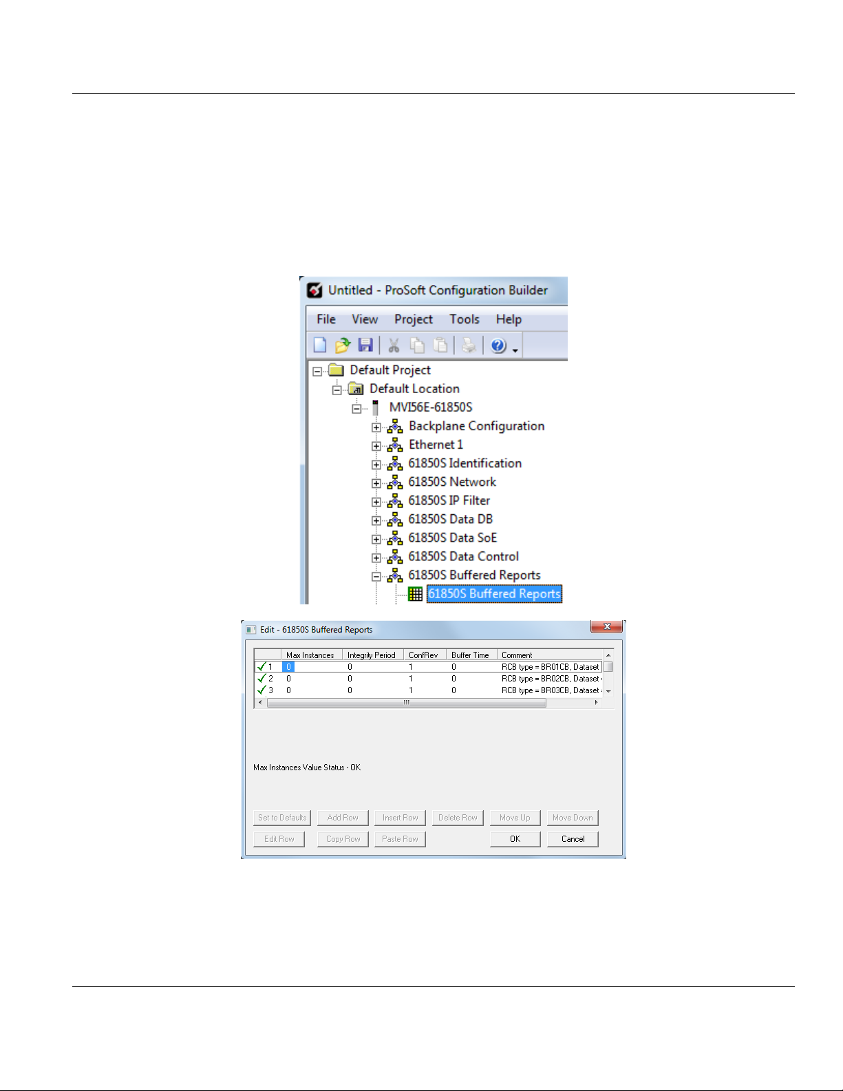
3.9 61850S Buffered Reports
A buffered report logs the changes in data if the IEC 61850 client/server connection has
been lost. Once the connection has be re-established, the report can be sent upon
condition.
1 Double-click the 61850S BUFFERED REPORTS icon to open the configuration window.
2 Double-click on the row to be edited.
Page 34 of 81 ProSoft Technology, Inc.
September 4, 2014
Page 35
MVI56E-61850S ♦ ControlLogix Platform Contents
Name
Range
Description
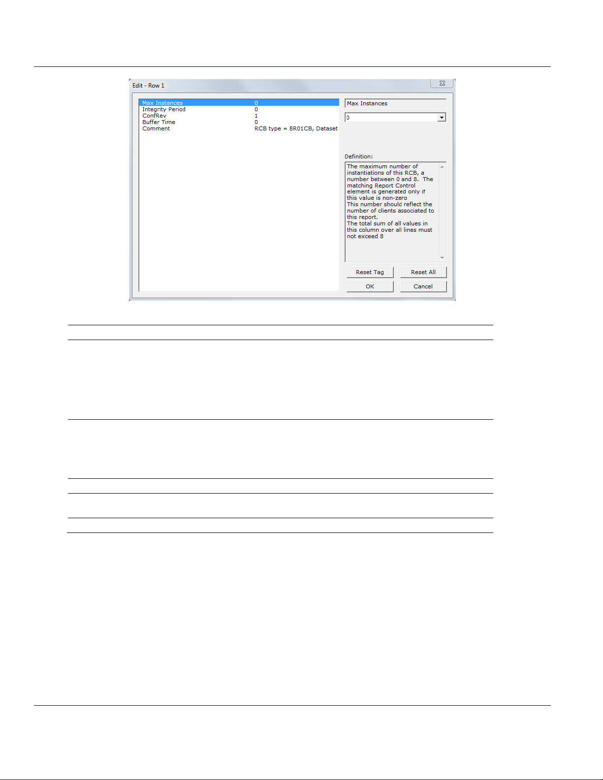
Max Instances
0 to 8
Maximum number of instantiations of this RCB. The matching
Report Control element is generated only if this value is nonzero.
This number should reflect the number of clients associated to
this report.
The total sum of all values in this column over all lines must not
exceed 8.
Integrity Period
0 to 2,147,483,647
The integrity period for this report in milliseconds, at which the
module will send the report to the client associated to this report.
This value may be overridden by the 61850 client during the
report-enable sequence.
0 = Disabled
ConfRev
0 to 2,147,483,647
Number of reconfigurations of the report's associated dataset
Buffer Time
0 to 65535
Maximum amount of time, in milliseconds, that buffered events
will be held pending before being reported.
Comment
User defined
IEC 61850 Server Communication Module User Manual
ProSoft Technology, Inc. Page 35 of 81
September 4, 2014
Page 36
Contents MVI56E-61850S ♦ ControlLogix Platform
User Manual IEC 61850 Server Communication Module
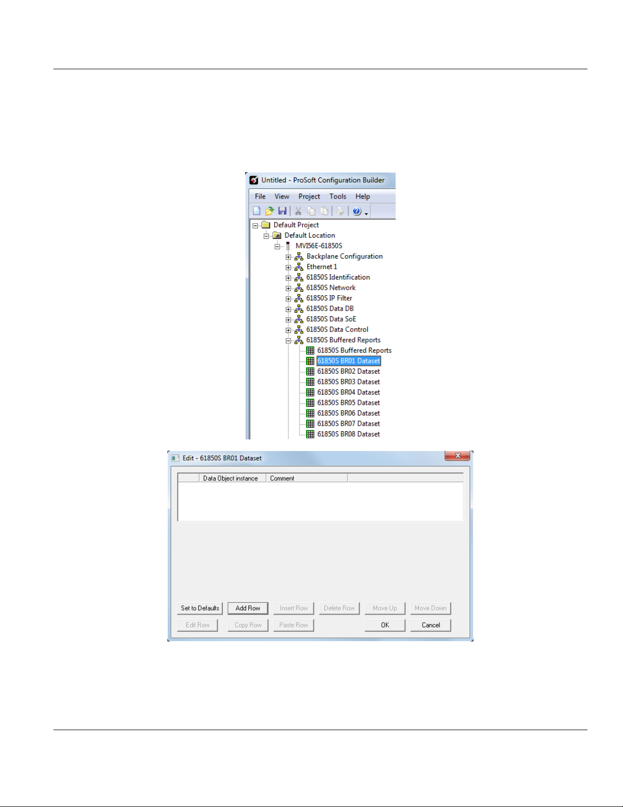
3.9.1 61850S BR0x Dataset
This section allows you to set up datasets for data objects for buffered reports.
1 Double-click the 61850S BR0X DATASET icon to open the configuration window.
2 Click ADD ROW then EDIT ROW to edit.
Page 36 of 81 ProSoft Technology, Inc.
September 4, 2014
Page 37

MVI56E-61850S ♦ ControlLogix Platform Contents
Name
Description
Data Object
Instance
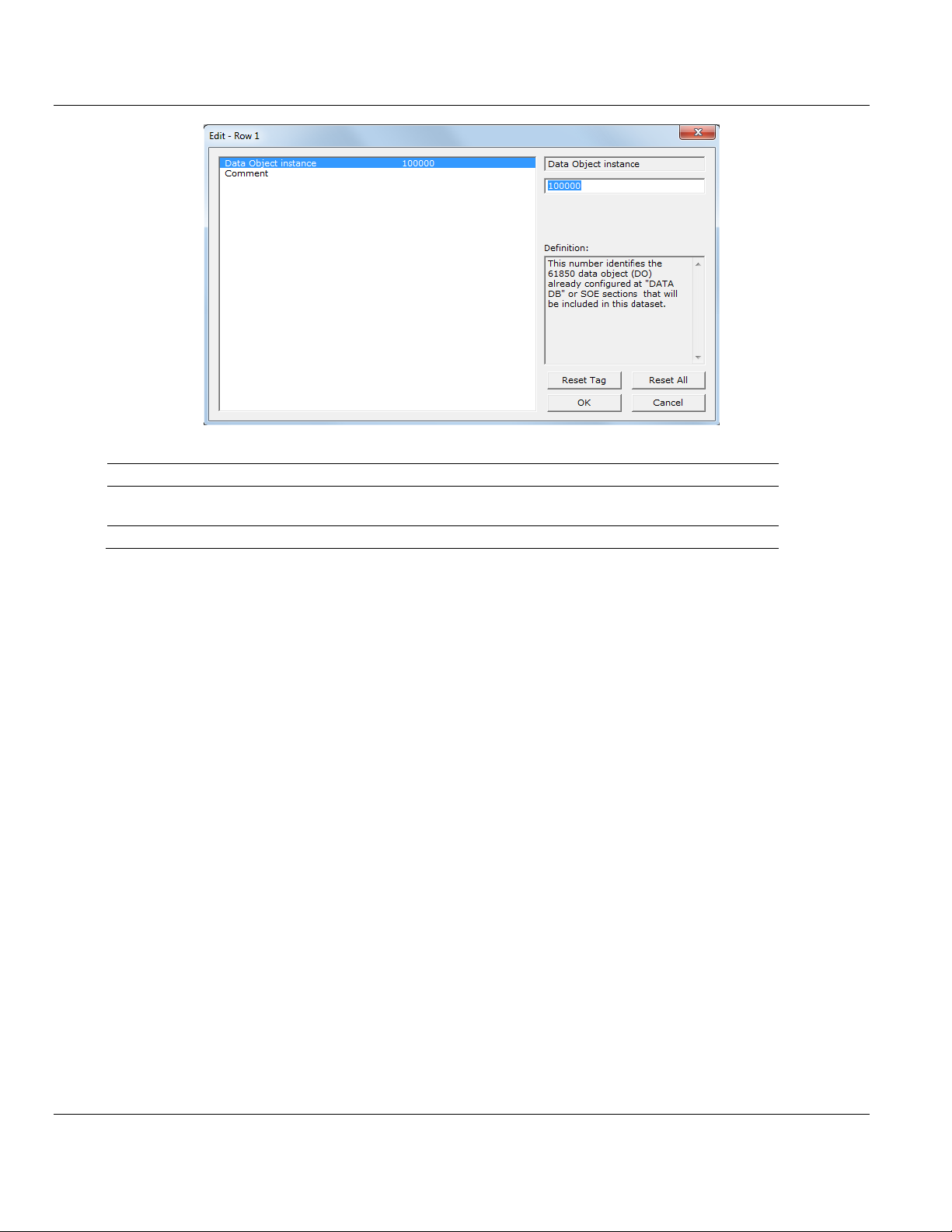
This value identifies the 61850 data object (DO) number already configured at
"DATA DB" or SoE sections that will be included in this dataset.
Comment
User defined
IEC 61850 Server Communication Module User Manual
ProSoft Technology, Inc. Page 37 of 81
September 4, 2014
Page 38

Contents MVI56E-61850S ♦ ControlLogix Platform
User Manual IEC 61850 Server Communication Module
3.10 61850S Unbuffered Reports
An unbuffered report logs a change in data if the IEC 61850 client/server connection has
been lost. Once the connection has be re-established, only the last reported data change
will be sent.
1 Double-click the 61850S UNBUFFERED REPORTS icon to open the configuration window.
2 Double-click on the row to be edited.
Page 38 of 81 ProSoft Technology, Inc.
September 4, 2014
Page 39
MVI56E-61850S ♦ ControlLogix Platform Contents
Name
Range
Description
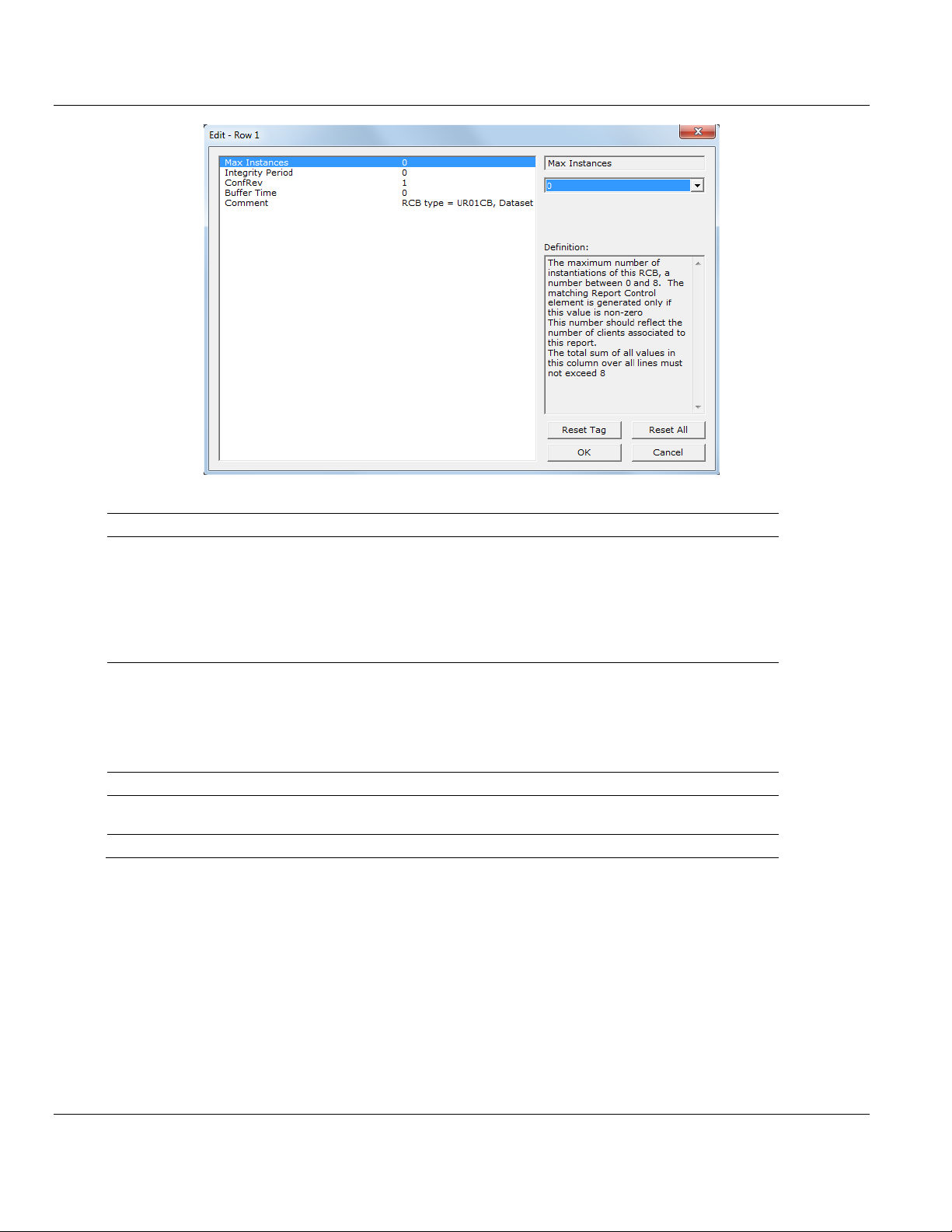
Max Instances
0 to 8
Maximum number of instantiations of this RCB. The matching
Report Control element is generated only if this value is nonzero.
This number should reflect the number of clients associated to
this report.
The total sum of all values in this column over all lines must
not exceed 8.
Integrity Period
0 to 2,147,483,647
The integrity period for this report in milliseconds, at which the
module will send the report to the client associated to this
report.
This value may be overridden by the 61850 client during the
report-enable sequence.
0 = Disabled
ConfRev
0 to 2,147,483,647
Number of reconfigurations of the report's associated dataset
Buffer Time
0 to 65535
Maximum amount of time, in milliseconds, that buffered events
will be held pending before being reported.
Comment
User defined
IEC 61850 Server Communication Module User Manual
ProSoft Technology, Inc. Page 39 of 81
September 4, 2014
Page 40
Contents MVI56E-61850S ♦ ControlLogix Platform
User Manual IEC 61850 Server Communication Module
3.10.1 61850S UR0x Dataset
This section allows you to set up datasets for data objects for unbuffered reports.
1 Double-click the 61850S BR0X DATASET icon to open the configuration window.
2 Click ADD ROW then EDIT ROW to edit.
Page 40 of 81 ProSoft Technology, Inc.
September 4, 2014
Page 41
MVI56E-61850S ♦ ControlLogix Platform Contents
Name
Description
Data Object
Instance
This value identifies the 61850 data object (DO) number already configured at
"DATA DB" or SoE sections that will be included in this dataset.
Comment
User defined
IEC 61850 Server Communication Module User Manual
ProSoft Technology, Inc. Page 41 of 81
September 4, 2014
Page 42

Contents MVI56E-61850S ♦ ControlLogix Platform
User Manual IEC 61850 Server Communication Module
3.11 Downloading the Project to the Module
In order for the module to use the settings you configured, you must download (copy) the
updated Project file from your PC to the module.
1 In the tree view in ProSoft Configuration Builder, right-click the MVI56E-61850S icon to
open a shortcut menu.
2 Choose DOWNLOAD FROM PC TO DEVICE. This opens the Download dialog box.
3 In the Download dialog box, choose the connection type in the Select Connection Type
dropdown box:
o Choose ETHERNET if you are connecting to the module through the Ethernet cable.
o Choose 1756 ENBT if you are connecting to the module through CIPconnect or
RSWho.
Refer to Connecting Your PC to the Module's Ethernet Port (Page 44) for more
information.
Note: If you connected to the module using an Ethernet cable and set a temporary IP address, the Ethernet
address field contains that temporary IP address. ProSoft Configuration Builder uses this temporary IP address
to connect to the module.
4 Click TEST CONNECTION to verify that the IP address allows access to the module.
5 If the connection succeeds, click DOWNLOAD to transfer the Ethernet configuration to the
module.
Page 42 of 81 ProSoft Technology, Inc.
September 4, 2014
Page 43
MVI56E-61850S ♦ ControlLogix Platform Contents
IEC 61850 Server Communication Module User Manual
If the Test Connection procedure fails, you will see an error message. To correct the error,
follow these steps.
1 Click OK to dismiss the error message.
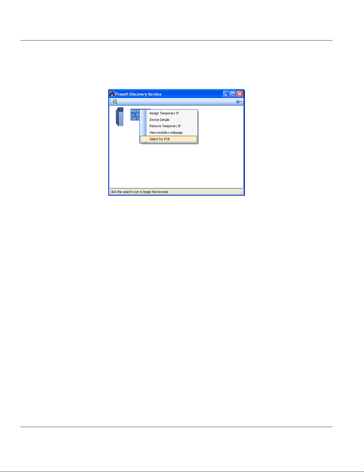
2 In the Download dialog box, click BROWSE DEVICE(S) to open ProSoft Discovery Service.
3 Select the module, and then click the right mouse button to open a shortcut menu. On
the shortcut menu, choose SELECT FOR PCB.
4 Close ProSoft Discovery Service.
5 Click DOWNLOAD to transfer the configuration to the module.
ProSoft Technology, Inc. Page 43 of 81
September 4, 2014
Page 44

Contents MVI56E-61850S ♦ ControlLogix Platform
User Manual IEC 61850 Server Communication Module
3.11.1 Connecting Your PC to the Module's Ethernet Port
With the module securely mounted, connect one end of the Ethernet cable to the Config
(E1) Port, and the other end to an Ethernet hub or switch accessible from the same network
as your PC. You can also connect directly from the Ethernet Port on your PC to the Config
(E1) Port on the module by using an Ethernet crossover cable (not included).
Setting Up a Temporary IP Address
Important: ProSoft Configuration Builder locates MVI56E-61850S modules through UDP broadcast messages.
These messages may be blocked by routers or layer 3 switches. In that case, ProSoft Discovery Service will be
unable to locate the modules.
To use ProSoft Configuration Builder, arrange the Ethernet connection so that there is no router/ layer 3 switch
between the computer and the module OR reconfigure the router/ layer 3 switch to allow routing of the UDP
broadcast messages.
1 In the tree view in ProSoft Configuration Builder, select the MVI56E-61850S module.
Page 44 of 81 ProSoft Technology, Inc.
September 4, 2014
Page 45

MVI56E-61850S ♦ ControlLogix Platform Contents
IEC 61850 Server Communication Module User Manual
2 Click the right mouse button to open a shortcut menu. On the shortcut menu, choose
DIAGNOSTICS.
3 In the Diagnostics window, click the SET UP CONNECTION button.
4 In the Connection Setup dialog box, click the BROWSE DEVICE(S) button to open the
ProSoft Discovery Service. Select the module, then right-click and choose ASSIGN
TEMPORARY IP.
ProSoft Technology, Inc. Page 45 of 81
September 4, 2014
Page 46

Contents MVI56E-61850S ♦ ControlLogix Platform
User Manual IEC 61850 Server Communication Module
5 The module’s default IP address is 192.168.0.250. Choose an unused IP within your
subnet, and then click OK.
Important: The temporary IP address is only valid until the next time the module is initialized. For information on
how to set the module’s permanent IP address, see Ethernet Configuration.
6 Close the ProSoft Discovery Service window. Enter the temporary IP in the Ethernet
address field of the Connection Setup dialog box, then click the TEST CONNECTION button
to verify that the module is accessible with the current settings.
7 If the Test Connection is successful, click CONNECT. The Diagnostics menu will display
in the Diagnostics window.
Page 46 of 81 ProSoft Technology, Inc.
September 4, 2014
Page 47

MVI56E-61850S ♦ ControlLogix Platform Contents
IEC 61850 Server Communication Module User Manual
Using RSWho to Connect to the Module
You need to have RSLinx installed on your PC to use this feature. You also need an ENBT module set up in the
rack. For information on setting up the ENBT module, see Using CIPconnect to Connect to the Module.
1 In the tree view in ProSoft Configuration Builder, right-click the MVI56E-61850S module.
2 From the shortcut menu, choose DOWNLOAD FROM PC TO DEVICE.
3 In the Download dialog box, choose 1756 ENBT from the Select Connection Type
dropdown box.
4 Click RSWHO to display modules on the network. The MVI56E-61850S module will
automatically be identified on the network.
5 Select the module, and then click OK.
ProSoft Technology, Inc. Page 47 of 81
September 4, 2014
Page 48

Contents MVI56E-61850S ♦ ControlLogix Platform
User Manual IEC 61850 Server Communication Module
Page 48 of 81 ProSoft Technology, Inc.
September 4, 2014
Page 49

MVI56E-61850S ♦ ControlLogix Platform Contents
In This Chapter
MVI56E-61850S User-Defined Data Types ...........................................49
MVI56E-61850S Controller Tags ...........................................................49
Name
Description
MVI56E61850S.DATA
MVI56E-61850S input and output data transferred between the
processor and the module
MVI56E61850S.COMMAND
Governs the data movement between the PLC rack and the module
MVI56E61850S.STATUS
Status data
MVI56E61850S.UTIL
Generic tags used for internal ladder processing (DO NOT MODIFY)
IEC 61850 Server Communication Module User Manual
4 RSLogix 5000 Configuration
Although the MVI56E-61850S configuration is done in PCB, it is maintained in the
MVI56E61850S controller tags of RSLogix 5000. This chapter covers the tag structure and
locations of the MVI56E-61850S parameters in RSLogix 5000.
4.1 MVI56E-61850S User-Defined Data Types
The sample ladder logic relies heavily on the use of User-Defined Data Types (UDTs) to
help group and structure the wide variety and volume of data and control features the
module offers. Lower-order UDT structures are often embedded in higher-order structures to
help further organize data into more easily understood data collections.
All data and control parameters related to the MVI56E-61850S are contained in Userdefined Data Types (UDTs). The MVI56E61850S_MODULEDEF UDT is the primary, top
level data structure in which all other lower-order data types are grouped and organized. All
groups branch down from this UDT.
To utilize all the features and functions of the module, an instance of each data type is
required. This is accomplished by declaring controller tag variables using these data types in
the Controller Tags Edit Tags dialog box.
Some UDTs hold process or status data (Module Data Objects). This data can be monitored
and manipulated by the application-specific ladder logic program. Other UDTs are used to
store and organize the parameters needed for special functions and control features
(Special Data Objects). These data types will be discussed in more detail in succeeding
topics.
4.2 MVI56E-61850S Controller Tags
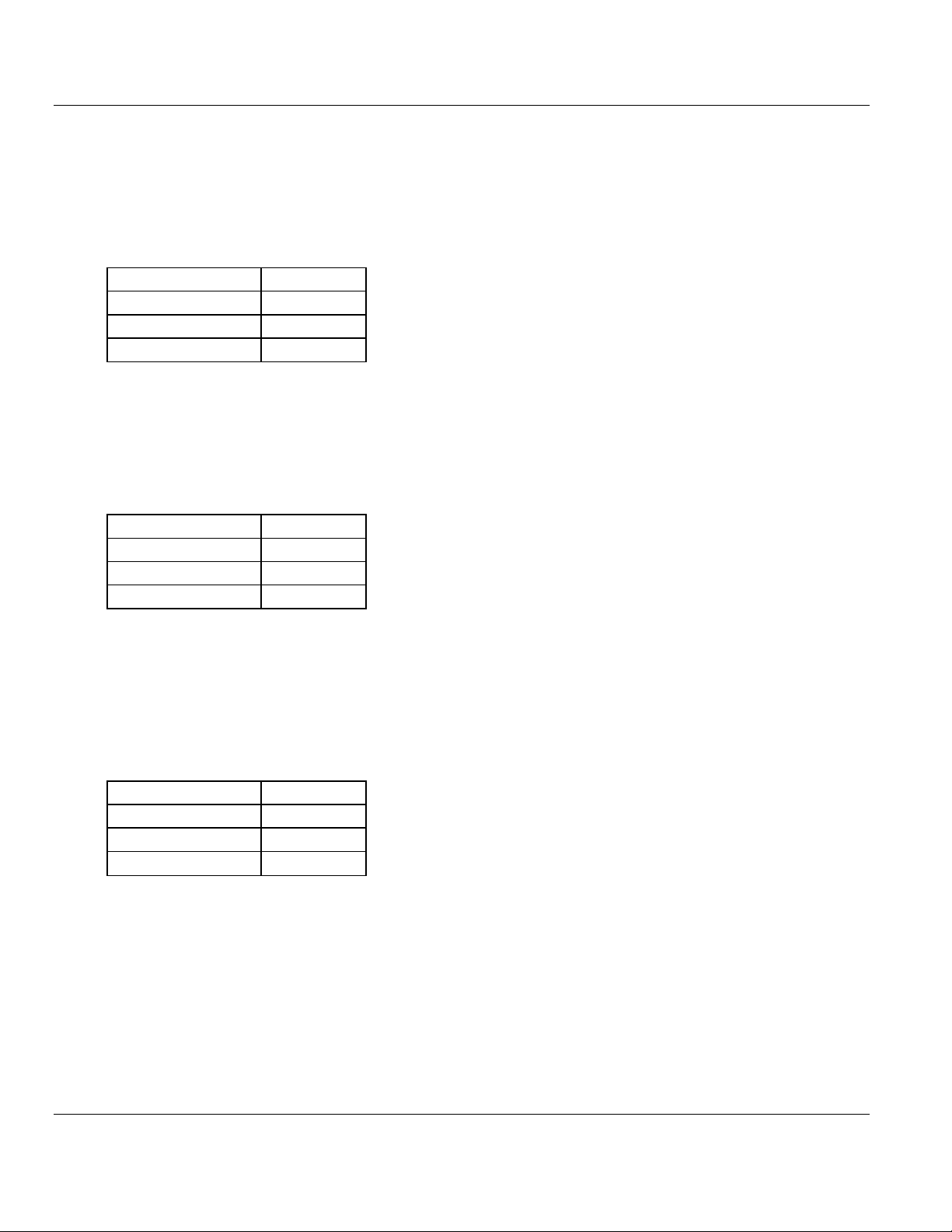
4.2.1 61850S Controller Tag Overview
ProSoft Technology, Inc. Page 49 of 81
September 4, 2014
Page 50

Contents MVI56E-61850S ♦ ControlLogix Platform
MVI56E61850S.DATA.DATA_DB.
Description
Database.WriteData[x]
MVI56E-61850S database array written from processor to the module.
MVI56E61850S.DATA.SOE.
Description
BOOL
Array contains the tags to populate and trigger SoE Boolean data
SINT
Array contains the tags to populate and trigger SoE SINT data
INT
Array contains the tags to populate and trigger SoE INT data
DINT
Array contains the tags to populate and trigger SoE DINT data
REAL
Array contains the tags to populate and trigger SoE REAL data
FLOATDB
Array contains the tags to populate and trigger SoE FLOATDB data
MVI56E61850S.DATA.CONTROL.
Description
BOOL
Array contains the tags to populate and trigger Control Boolean data
SINT
Array contains the tags to populate and trigger Control SINT data
INT
Array contains the tags to populate and trigger Control INT data
DINT
Array contains the tags to populate and trigger Control DINT data
REAL
Array contains the tags to populate and trigger Control REAL data
User Manual IEC 61850 Server Communication Module
4.2.2 MVI56E61850S.DATA
This array contains the tags used for data transfer (Database, Sequence of Event and
Control). Values written to or received from a remote 61850 client are populated here. Setup
information can be found in Examples (page 53).
Data DB
Sequence of Event (SoE)
Control
Page 50 of 81 ProSoft Technology, Inc.
September 4, 2014
Page 51

MVI56E-61850S ♦ ControlLogix Platform Contents
MVI56E61850S.COMMAND.TIME.
Description
GetProcessorTime
Reads date/time from processor to TIME tag
GetModuleTime
Reads date/time from module to TIME tag
SetModuleTime
Writes date/time from TIME tag to the module
DisableFirstScanGetProcessorTime
0 = Prevents the logic to update TIME from processor time during first
scan
TIME
Date/time to be read/written between the processor and module
MVI56E61850S.COMMAND.CONTROL.
Description
Auto_Ack
ON = Automatically ack every control block.
OFF = User must ack every control block using own logic
User_Ack
When Auto_ACK = OFF, this bit can be used to ack the last control. The
logic will ack with UTIL.ControlAck structure.
Reset_Pending
Resets pending bit without sending ack back to module. This can be used
so the logic can spend multiple scans preparing the ack
Pending
Automatically set to ON once new control block is received. Automatically
reset to OFF once control is acknowledged.
MVI56E61850S.COMMAND.BOOT.
Description
Warmboot
Warmboots the module
Coldboot
Coldboots the module
Coldboot_Reset_SOE_Data
Coldboots the module and resets SoE data stored in the processor
Coldboot_Reset_Control_Data
Coldboots the module and resets Control data stored in processor
IEC 61850 Server Communication Module User Manual
4.2.3 MVI56E61850S.COMMAND
This array includes the control of module time, control block acknowledgement, and reboot
commands.
Time operations for reading/writing time values between the processor and the module:
Control acknowledgement and its status:
Module reboot commands:
ProSoft Technology, Inc. Page 51 of 81
September 4, 2014
Page 52

Contents MVI56E-61850S ♦ ControlLogix Platform
MVI56E61850S.STATUS.
Description
ScanCounter
Scan counter increments at every module scan of the ladder logic
BackplanePhase
0 = Running
2 = Init/Initialize SoE/Control data from Processor
4 = InitTransfer PointIDs
6 = Init/Set clock
7 = InitWaiting Processor
ProductCode
Product Code 61S5
Firmware
Firmware version information
Backplane
Backplane statistics between the module and processor including read/write
data block counts, block error counts, DB, SoE, and Control block counts.
General
General diagnostics including initialization error, time-stamp module and
connection statistics.
Connection
Diagnostics for each of the 8 client connections including time-stamp, IP
address, and data packet status.
User Manual IEC 61850 Server Communication Module
4.2.4 MVI56E61850S.STATUS Tag
This array contains the overall module status.
4.2.5 MVI56E61850S.UTIL Tag
The UTIL array is used for internal ladder implementation. Do not update or delete these
tags.
Page 52 of 81 ProSoft Technology, Inc.
September 4, 2014
Page 53

MVI56E-61850S ♦ ControlLogix Platform Contents
In This Chapter
Data DB Example ..................................................................................53
SoE Example .........................................................................................58
Control Example ....................................................................................62
IEC 61850 Server Communication Module User Manual
5 Examples
This chapter includes examples of setting up the module for Data DB, SoE, and Control data
exchange.
5.1 Data DB Example
This example shows how to set up boolean, integer, and real DB data objects (DO's). In this
section, you will configure the PCB file, edit a data value in RSLogix 5000, and verify the
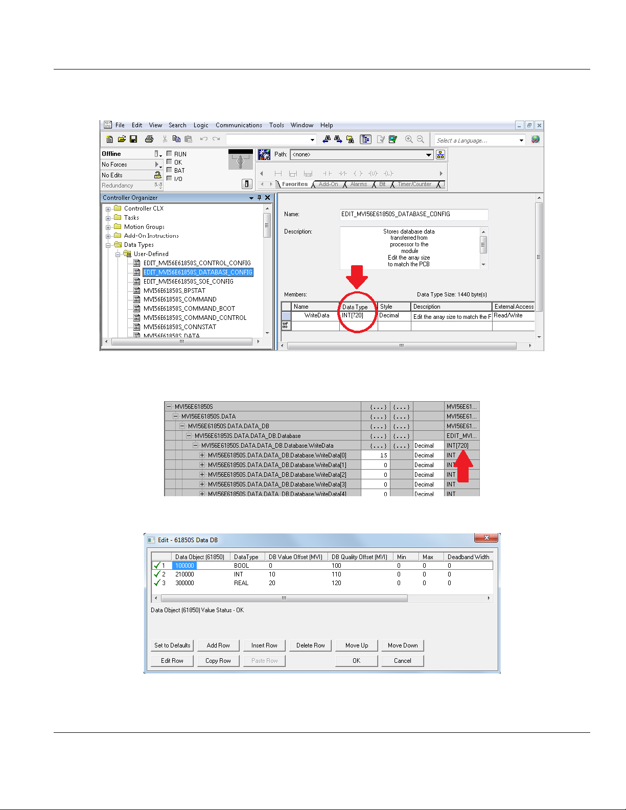
value has been updated in module memory.
1 In PCB, enter 720 in the Write Register Count parameter value. The module breaks
down this data into blocks of 240 words. Therefore 720 words will cause the module to
generate 3 data blocks to be transferred between the processor and the module.
ProSoft Technology, Inc. Page 53 of 81
September 4, 2014
Page 54
Contents MVI56E-61850S ♦ ControlLogix Platform
User Manual IEC 61850 Server Communication Module
2 In RSLogix 5000, edit the EDIT_MVI56E61850S_DATABASE_CONFIG User-Defined
Data Type to 720:
3 The MVI56E61850S.DATA.DATA_DB.Database.WriteData array now contains 720
elements. The sample ladder will adjust to accommodate the 3 data blocks needed.
4 In PCB, configure the DO's in the 61850S Data DB section.
Page 54 of 81 ProSoft Technology, Inc.
September 4, 2014
Page 55
MVI56E-61850S ♦ ControlLogix Platform Contents
Data Object
100000
Data Type
BOOL
DB Value Offset
0
DB Quality Offset
100
Data Object
210000
Data Type
INT
DB Value Offset
10
DB Quality Offset
110
Data Object
300000
Data Type
REAL
DB Value Offset
20
DB Quality Offset
120
IEC 61850 Server Communication Module User Manual
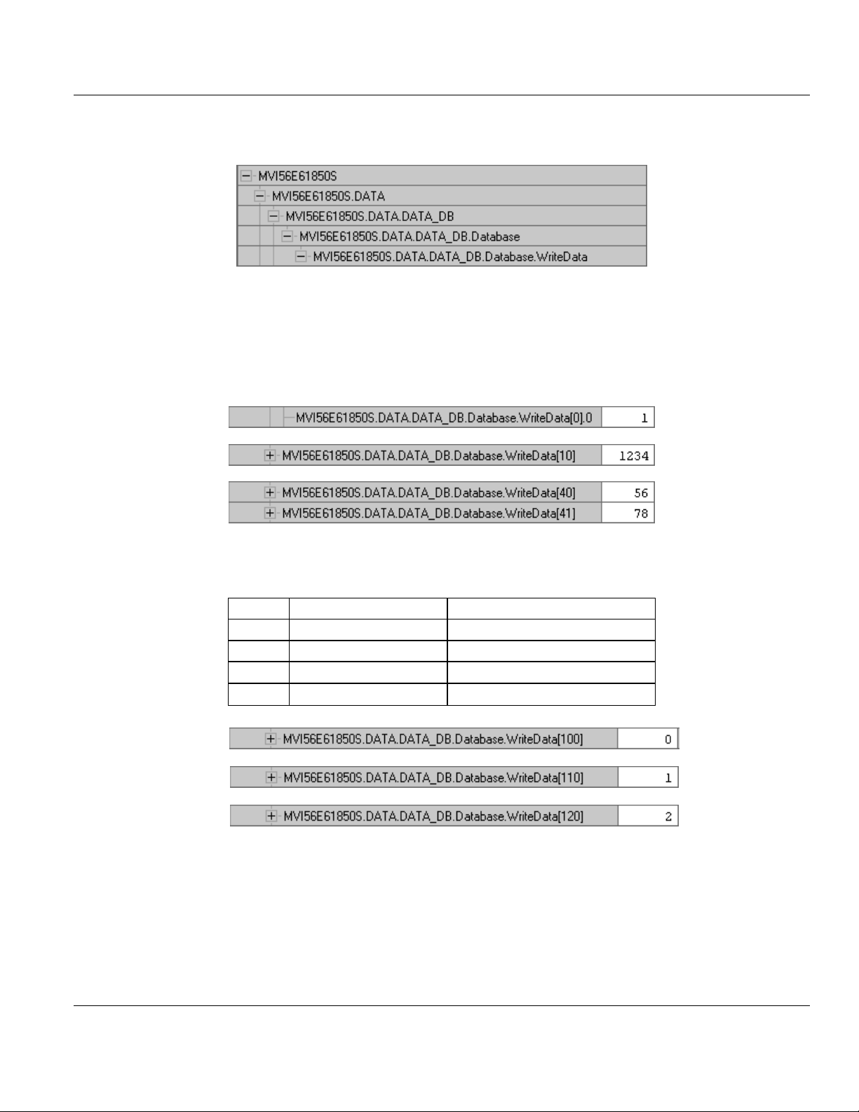
For Boolean data, enter the following values. One bit of data will be allotted for this DO in
the module's internal memory register 0, bit 0. This location corresponds to
MVI56E61850S.DATA.DATA_DB.Database.WriteData[0].0 in RSLogix 5000.
An (optional) quality byte value is assigned to module memory 100. This location
corresponds to the least significant byte in
MVI56E61850S.DATA.DATA_DB.Database.WriteData[50] in RSLogix 5000.
For Integer data, enter the following values. A 16-bit register will be allotted for this DO in
the module's internal memory register 10. This location corresponds to
MVI56E61850S.DATA.DATA_DB.Database.WriteData[10] in RSLogix 5000.
An (optional) quality byte value is assigned to module memory 110. This location
corresponds to the least significant byte in
MVI56E61850S.DATA.DATA_DB.Database.WriteData[55] in RSLogix 5000.
For Real data, enter the following values. A 32-bit value (stored as two 16-bit registers) will
be allotted for this DO in the module's internal memory register 20. This location
corresponds to MVI56E61850S.DATA.DATA_DB.Database.WriteData[40] and [41] in
RSLogix 5000.
An (optional) quality byte value is assigned to module memory 100. This location
corresponds to the least significant byte in
MVI56E61850S.DATA.DATA_DB.Database.WriteData[60] in RSLogix 5000.
5 Save and download the PCB file to the module. For more information, see Downloading
the Sample Program to the Processor (page 13)
ProSoft Technology, Inc. Page 55 of 81
September 4, 2014
Page 56
Contents MVI56E-61850S ♦ ControlLogix Platform
Value
61850 Quality Validity
Descripiton
0
Good
No bit set
1
Questionable
Old data bit set
2
Invalid
Oscillatory bit set
3
Invalid
Old data and oscillatory bits set
User Manual IEC 61850 Server Communication Module
6 With the processor in RUN mode in RSLogix 5000, locate the
MVI56E61850S.DATA.DATA_DB.Database.WriteData array.
7 Enter arbitrary values in each of the corresponding tags for the Boolean, Integer, and
Real points configured in PCB.
Boolean: MVI56E61850S.DATA.DATA_DB.Database.WriteData[0].0
Integer: MVI56E61850S.DATA.DATA_DB.Database.WriteData[10]
Real: MVI56E61850S.DATA.DATA_DB.Database.WriteData[40] and [41]
8 Enter the Quality value describing the data integrity of each DO. This memory address
corresponds to the DB Quality Offset parameter in PCB above.
9 The MVI56E-61850S ladder logic sends these values over the backplane to the MVI56E-
61850S module memory on every scan.
10 Verify the values of the module memory by viewing the MVI56E-61850S database in the
PCB. For more information, see Using the Diagnostics Menu in ProSoft Configuration
Builder
Page 56 of 81 ProSoft Technology, Inc.
September 4, 2014
Page 57

MVI56E-61850S ♦ ControlLogix Platform Contents
IEC 61850 Server Communication Module User Manual
11 In the Diagnostics window, click on 61850 SERVER - DATA MAPPINGS > DB - Paths
& Values. The DO and quality values are displayed here.
ProSoft Technology, Inc. Page 57 of 81
September 4, 2014
Page 58

Contents MVI56E-61850S ♦ ControlLogix Platform
Data Object
400000
Data Type
BOOL
Point ID
1
Data Object
510000
Data Type
INT
Point ID
2
Data Object
600000
Data Type
REAL
Point ID
3
User Manual IEC 61850 Server Communication Module
5.2 SoE Example
This example shows how to set up boolean, integer, and real Sequence of Event (SoE) data
objects (DO's). In this section, you will configure the PCB file, edit events in RSLogix 5000,
and verify the value has been updated in module memory.
1 In PCB, configure the DB points in the 61850S Data DB section.
For Boolean data, enter the following values. One bit of data will be allotted for this DO.
For Integer data, enter the following values. A 16-bit register will be allotted for this DO.
For Real data, enter the following values. A 32-bit value (stored as two 16-bit registers) will
be allotted for this DO.
2 Save and download the PCB file to the module. For more information, see Downloading
the Sample Program to the Processor (page 13)
Page 58 of 81 ProSoft Technology, Inc.
September 4, 2014
Page 59
MVI56E-61850S ♦ ControlLogix Platform Contents
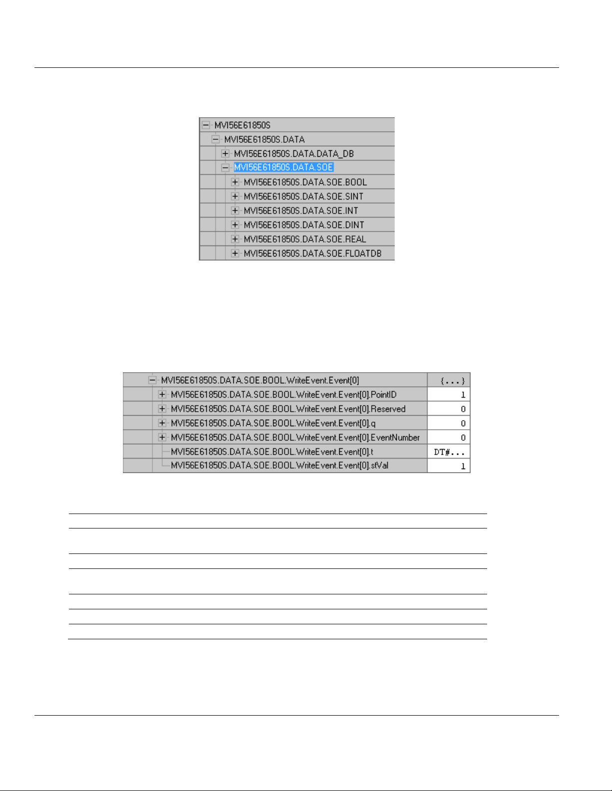
Event[0].
Value
Description
PointID
1
This value must match the corresponding BOOL Point ID parameter in
PCB
Reserved
-
Not used at this time
q 0 0 = Good data, No bit set, 1 = Questionable, Old data bit set
2 = Invalid, Oscillatory bit set, 3 = Old data and oscillatory bits set
EventNumber
-
Not used at this time
t
dd/tt
Date and time, Time-stamp of event
stVal
1
Data value: 0 = 'Off', 1 = 'On' (BOOL)
IEC 61850 Server Communication Module User Manual
3 With the processor in RUN mode in RSLogix 5000, locate the
MVI56E61850S.DATA.SOE array.
4 In order for the SoE data to be sent from the processor to the module, you must
populate then trigger an event in this array. You can send the event(s) in a consecutive
group or all at once (up to 24).
5 For Boolean data, locate the MVI56E61850S.DATA.SOE.BOOL.WriteEvent.Event[x]
array. All boolean SoE data will be populated in this array. Enter the values as shown
below. (These steps also apply to SINT, INT, DINT, REAL DO's)
BOOL
ProSoft Technology, Inc. Page 59 of 81
September 4, 2014
Page 60

Contents MVI56E-61850S ♦ ControlLogix Platform
Event[1].
Value
Description
PointID
2
This value must match the corresponding INT Point ID parameter in PCB
Reserved
-
Not used at this time
q 0 0 = Good data, No bit set, 1 = Questionable, Old data bit set
2 = Invalid, Oscillatory bit set, 3 = Old data and oscillatory bits set
EventNumber
-
Not used at this time
t
dd/tt
Date and time, Time-stamp of event
stVal
4321
Data value
Event[2].
Value
Description
PointID
3
This value must match the corresponding REAL Point ID parameter in PCB
Reserved
-
Not used at this time
q 0 0 = Good data, No bit set, 1 = Questionable, Old data bit set
2 = Invalid, Oscillatory bit set, 3 = Old data and oscillatory bits set
EventNumber
-
Not used at this time
t
dd/tt
Date and time, Time-stamp of event
stVal
99.9
Data value
User Manual IEC 61850 Server Communication Module
INT
REAL
6 Once these values are populated, enter the number of boolean events to be sent to the
module.
7 To send the data to the module, enter 1 in the
MVI56E61850S.DATA.SOE.BOOL.WriteEvent.Trigger tag. It will reset back to 0 once
triggered.
Page 60 of 81 ProSoft Technology, Inc.
September 4, 2014
Page 61

MVI56E-61850S ♦ ControlLogix Platform Contents
IEC 61850 Server Communication Module User Manual
8 Verify the values in module memory by viewing the MVI56E-61850S database in the
PCB. For more information, see Using the Diagnostics Menu in ProSoft Configuration
Builder
9 In the Diagnostics window, click on 61850 SERVER - DATA MAPPINGS > SoE - Paths
& Values. The DO values are displayed here.
ProSoft Technology, Inc. Page 61 of 81
September 4, 2014
Page 62
Contents MVI56E-61850S ♦ ControlLogix Platform
Data Object
700000
Data Type
BOOL
Point ID
11
Data Object
810000
Data Type
INT
Point ID
12
Data Object
900000
Data Type
REAL
Point ID
13
User Manual IEC 61850 Server Communication Module
5.3 Control Example
This example shows how to set up boolean, integer, and real Control data objects (DO's). In
this section, you will configure the PCB file, configure the related parameters in RSLogix
5000, and verify the value has been populated in module memory using an automatic
acknowledge feature.
When a IEC 61850 client sends Control DO data to the MVI56E-61850S, the MVI56E-
61850S passes this data to the processor. This data can be analyzed by the user's ladder
logic. Data with time-stamp and quality attributes can then be returned to the module for the
client to read.
The processor can also acknowledge the data with no user-logic needed, this feature is
enabled by default at MVI56E61850S.COMMAND.CONTROL.Auto_Ack.
1 In PCB, configure the DB points in the 61850S Data DB section.
For Boolean data, enter the following values. One bit of data will be allotted for this DO.
For Integer data, enter the following values. A 16-bit register will be allotted for this DO.
For Real data, enter the following values. A 32-bit value (stored as two 16-bit registers) will
be allotted for this DO.
Page 62 of 81 ProSoft Technology, Inc.
September 4, 2014
Page 63

MVI56E-61850S ♦ ControlLogix Platform Contents
BOOL[0].
Value
Description
PointID
11
This value must match the corresponding BOOL Point ID parameter in
PCB
Reserved
-
Not used at this time
q 0 0 = Good data, No bit set, 1 = Questionable, Old data bit set
2 = Invalid, Oscillatory bit set, 3 = Old data and oscillatory bits set
EventNumber
-
Not used at this time
t
dd/tt
Date and time, Time-stamp of event
stVal
1
Data value: 0 = 'Off', 1 = 'On'
IEC 61850 Server Communication Module User Manual
2 Save and download the PCB file to the module. For more information, see Downloading
the Sample Program to the Processor (page 13)
3 With the processor in RUN mode in RSLogix 5000, locate the
MVI56E61850S.DATA.SOE array.
4 For Boolean data, locate the MVI56E61850S.DATA.CONTROL.BOOL[x] array. All
boolean Control data will be populated in this array. Enter the values as shown below.
(These steps also apply to SINT, INT, DINT, REAL DO's)
BOOL
ProSoft Technology, Inc. Page 63 of 81
September 4, 2014
Page 64
Contents MVI56E-61850S ♦ ControlLogix Platform
INT[0].
Value
Description
PointID
12
This value must match the corresponding INT Point ID parameter in PCB
Reserved
-
Not used at this time
q 0 0 = Good data, No bit set, 1 = Questionable, Old data bit set
2 = Invalid, Oscillatory bit set, 3 = Old data and oscillatory bits set
EventNumber
-
Not used at this time
t
dd/tt
Date and time, Time-stamp of event
stVal
1000
Data value
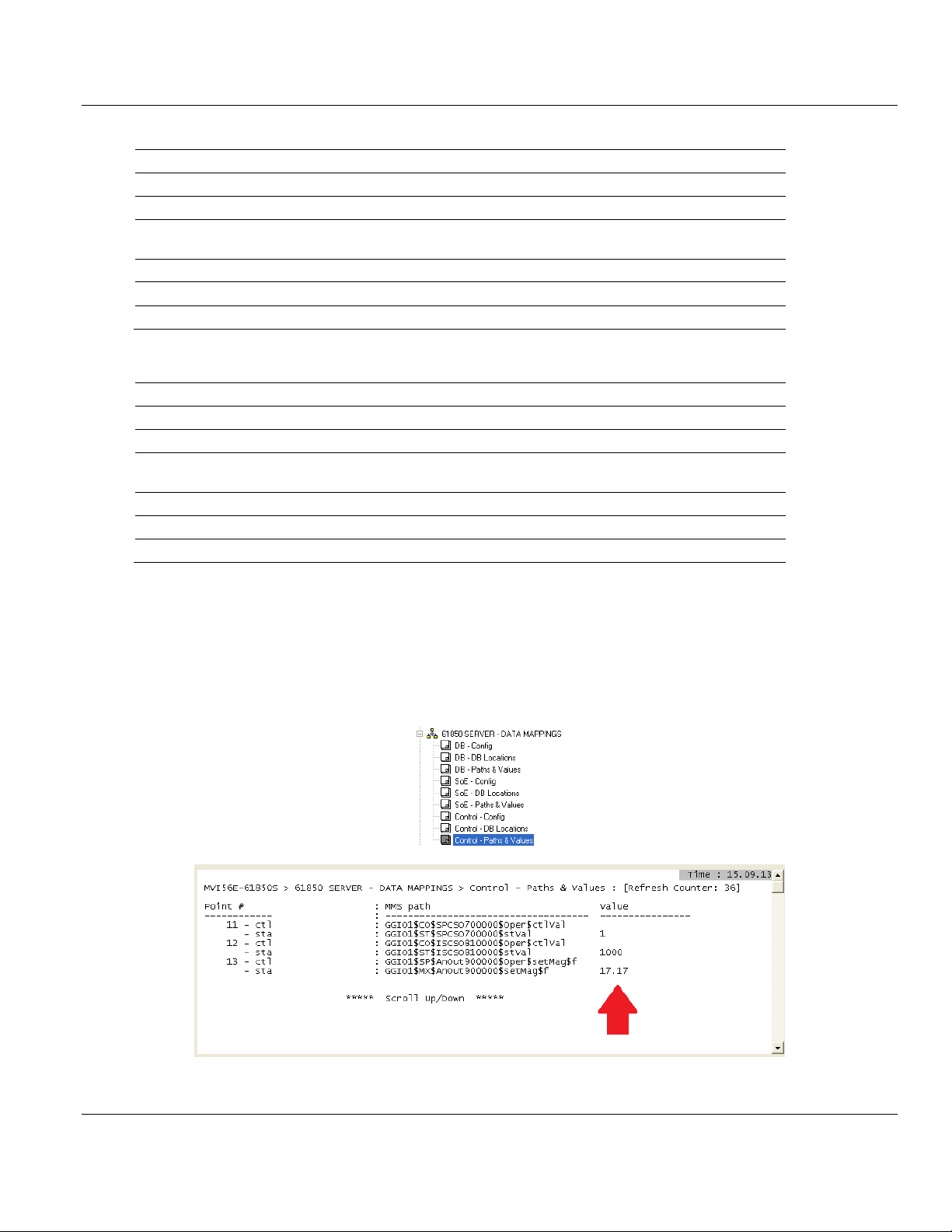
REAL[0].
Value
Description
PointID
13
This value must match the corresponding REAL Point ID parameter in PCB
Reserved
-
Not used at this time
q 0 0 = Good data, No bit set, 1 = Questionable, Old data bit set
2 = Invalid, Oscillatory bit set, 3 = Old data and oscillatory bits set
EventNumber
-
Not used at this time
t
dd/tt
Date and time, Time-stamp of event
stVal
17.17
Data value
User Manual IEC 61850 Server Communication Module
INT
REAL
5 Verify the acknowledged data in module memory by viewing the MVI56E-61850S
database in the PCB. For more information, see Using the Diagnostics Menu in ProSoft
Configuration Builder
6 In the Diagnostics window, click on 61850 SERVER - DATA MAPPINGS >
Control - Paths & Values. The DO values are displayed here.
Page 64 of 81 ProSoft Technology, Inc.
September 4, 2014
Page 65

MVI56E-61850S ♦ ControlLogix Platform Contents
In This Chapter
Ethernet LED Indicators .........................................................................65
Clearing a Fault Condition .....................................................................67
Troubleshooting .....................................................................................68
Using the Diagnostics Menu in ProSoft Configuration Builder ...............69
Connect to the Module’s Web Page ......................................................78
LED
State
Description
Data
OFF
Ethernet connected at 10Mbps duplex speed
AMBER Solid
Ethernet connected at 100Mbps duplex speed
Link
OFF
No physical network connection is detected. No Ethernet
communication is possible. Check wiring and cables.
GREEN Solid
or Blinking
Physical network connection detected. This LED must be ON solid
for Ethernet communication to be possible.
IEC 61850 Server Communication Module User Manual
6 Diagnostics and Troubleshooting
The module provides information on diagnostics and troubleshooting in the following forms:
LED status indicators on the front of the module provide information on the module’s
status.
Status data contained in the module can be viewed in ProSoft Configuration Builder
through the Ethernet port.
Status data values are transferred from the module to the processor.
6.1 Ethernet LED Indicators
The Ethernet LEDs indicate the module's Ethernet port status as follows:
ProSoft Technology, Inc. Page 65 of 81
September 4, 2014
Page 66

Contents MVI56E-61850S ♦ ControlLogix Platform
Code
Message
Boot / DDOK
Module is initializing
Ladd
Module is waiting for required module configuration data from
ladder logic to configure the ports
Waiting for Processor Connection
Module did not connect to processor during initialization
Sample ladder logic is not loaded on processor
Module is located in a different slot than the one
configured in the ladder logic
Processor is not in RUN or REM RUN mode
Last config: <date>
Indicates the last date when the module changed its IP
address. You can update the module date and time through
the Connect to the Module’s Web Page (page 78), or in
MVI56E-61850S controller tags.
Code
Message
<Backplane Status>
OK: Module is communicating with processor
ERR: Module is unable to communicate with processor. For
this scenario, the <Port Status> message above is replaced
with "Processor faulted or is in program mode".
<IP Address>
Module IP address
<Port Status>
OK: Port is communicating without error
Client/Server Communication Errors: port is having
communication errors. Refer to Diagnostics and
Troubleshooting (page 65) for further information about the
error.
User Manual IEC 61850 Server Communication Module
6.1.1 Scrolling LED Status Indicators
The scrolling LED display indicates the module’s operating status as follows:
Initialization Messages
Operation Messages
After the initialization step, the following message pattern will be repeated.
<Backplane Status> <IP Address> <Backplane Status> <Port Status>
Page 66 of 81 ProSoft Technology, Inc.
September 4, 2014
Page 67

MVI56E-61850S ♦ ControlLogix Platform Contents
LED Label
Status
Indication
APP
OFF
The module is not receiving adequate power or is not securely plugged
into the rack. May also be OFF during configuration download.
GREEN
The MVI56E-61850S is working normally.
RED
The most common cause is that the module has detected a
communication error during operation of an application port.
The following conditions may also cause a RED LED:
The firmware is initializing during startup
The firmware detects an on-board hardware problem during startup
Failure of application port hardware during startup
The module is shutting down
The module is rebooting due to a ColdBoot or WarmBoot request
from the ladder logic or Debug Menu
OK
OFF
The module is not receiving adequate power or is not securely plugged
into the rack.
GREEN
The module is operating normally.
RED
The module has detected an internal error or is being initialized. If the
LED remains RED for over 10 seconds, the module is not working.
Remove it from the rack and re-insert it to restart its internal program.
ERR
RED
Not used.
IEC 61850 Server Communication Module User Manual
6.1.2 Non-Scrolling LED Status Indicators
The non-scrolling LEDs indicate the module’s operating status as follows:
6.2 Clearing a Fault Condition
Typically, if the OK LED on the front of the module turns RED for more than ten seconds, a
hardware problem has been detected in the module or the program has exited.
To clear the condition, follow these steps:
1 Turn off power to the rack.
2 Remove the card from the rack.
3 Verify that all jumpers are set correctly.
4 If the module requires a Compact Flash card, verify that the card is installed correctly.
5 Re-insert the card in the rack and turn the power back on.
6 Verify correct configuration data is being transferred to the module from the ControlLogix
controller.
If the module's OK LED does not turn GREEN, verify that the module is inserted completely
into the rack. If this does not cure the problem, contact ProSoft Technology Technical
Support.
ProSoft Technology, Inc. Page 67 of 81
September 4, 2014
Page 68

Contents MVI56E-61850S ♦ ControlLogix Platform
Problem Description
Steps to take
Processor Fault
Verify that the module is plugged into the slot that has been configured
for the module in the I/O Configuration of RSLogix.
Verify that the slot location in the rack has been configured correctly in
the ladder logic.
Processor I/O LED
flashes
This indicates a problem with backplane communications. A problem
could exist between the processor and any installed I/O module, not just
the MVI56E-61850S. Verify that all modules in the rack are correctly
configured in the ladder logic.
Problem Description
Steps to take
MVI56E modules with
scrolling LED display:
<Backplane Status>
condition reads ERR
This indicates that backplane transfer operations are failing. Connect to
the module’s Configuration/Debug port to check this.
To establish backplane communications, verify the following items:
The processor is in RUN or REM RUN mode.
The backplane driver is loaded in the module.
The module is configured for read and write data block transfer.
The ladder logic handles all read and write block situations.
The module is properly configured in the processor I/O configuration
and ladder logic.
OK LED remains RED
The program has halted or a critical error has occurred. Connect to the
Configuration/Debug port to see if the module is running. If the program
has halted, turn off power to the rack, remove the card from the rack and
re-insert the card in the rack, and then restore power to the rack.
User Manual IEC 61850 Server Communication Module
6.3 Troubleshooting
Use the following troubleshooting steps if you encounter problems when the module is
powered up. If these steps do not resolve your problem, please contact ProSoft Technology
Technical Support.
Processor Errors
Module Errors
Page 68 of 81 ProSoft Technology, Inc.
September 4, 2014
Page 69
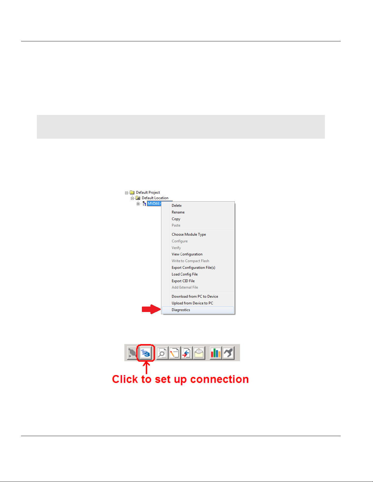
MVI56E-61850S ♦ ControlLogix Platform Contents
IEC 61850 Server Communication Module User Manual
6.4 Using the Diagnostics Menu in ProSoft Configuration Builder
The Diagnostics menu, available through the Ethernet configuration port for this module, is
arranged as a tree structure, with the Main menu at the top of the tree, and one or more
submenus for each menu command. The first menu you see when you connect to the
module is the Main menu.
Tip: You can have a ProSoft Configuration Builder Diagnostics window open for more than one module at a
time.
To connect to the module, refer to Connecting Your PC to the Module.
1 In the tree view in ProSoft Configuration Builder, right-click the MVI56E-61850S icon to
open a shortcut menu.
2 On the shortcut menu, choose DIAGNOSTICS.
3 In the Diagnostics window, click the SET UP CONNECTION button.
ProSoft Technology, Inc. Page 69 of 81
September 4, 2014
Page 70
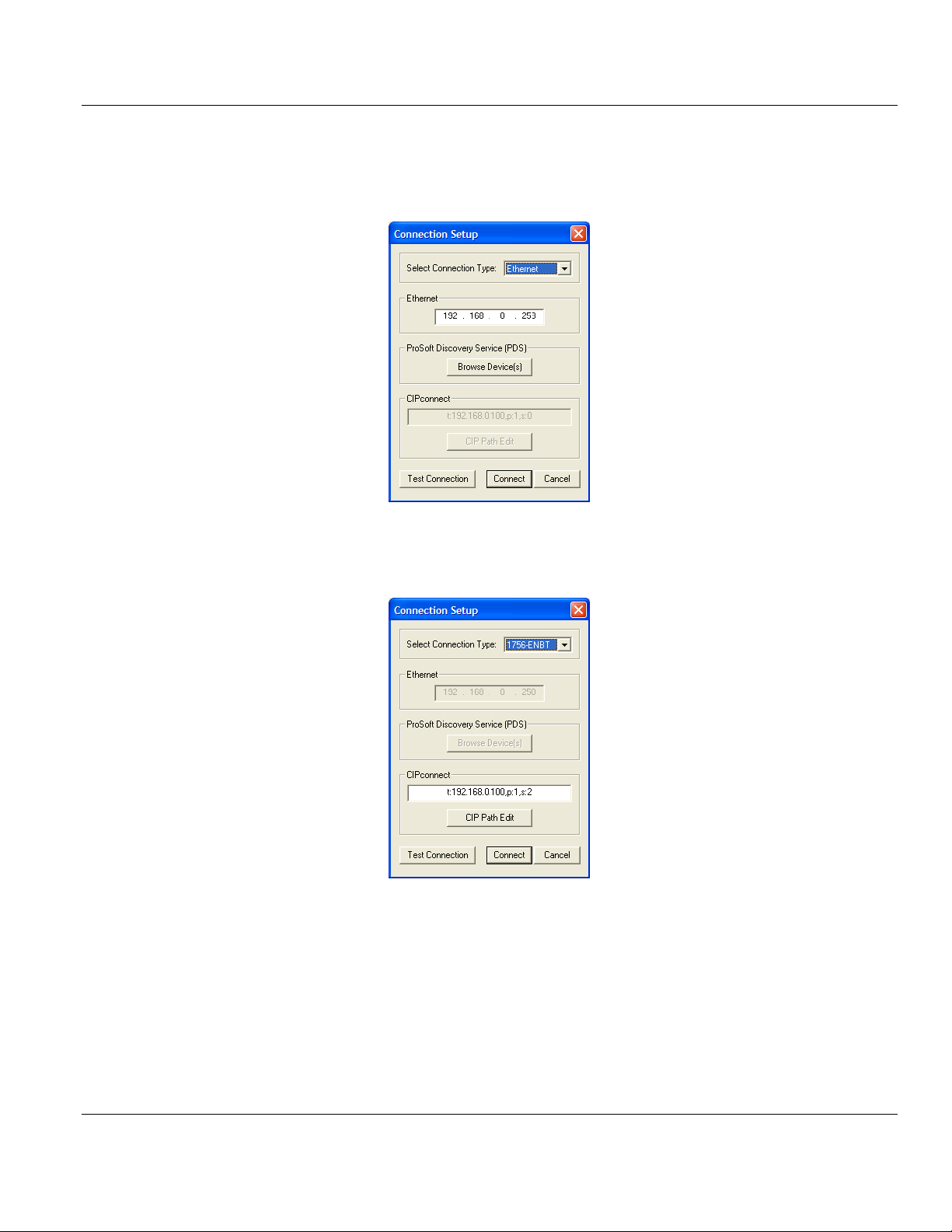
Contents MVI56E-61850S ♦ ControlLogix Platform
User Manual IEC 61850 Server Communication Module
4 In the Ethernet field of the Connection Setup dialog box, enter the IP address that was
assigned the module in Assigning a Permanent IP Address. In the Connection Setup
dialog box, click the TEST CONNECTION button to verify that the module is accessible with
the current settings.
You can also use CIPconnect® to connect to the module through a 1756-ENBT card by
choosing 1756-ENBT in the SELECT CONNECTION TYPE list. Refer to Using CIPconnect to
Connect to the Module for information on how to construct a CIP path.
Page 70 of 81 ProSoft Technology, Inc.
September 4, 2014
Page 71
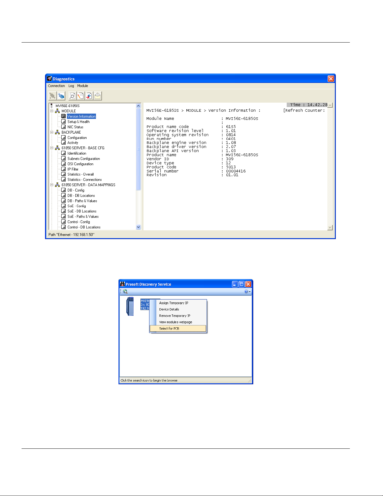
MVI56E-61850S ♦ ControlLogix Platform Contents
IEC 61850 Server Communication Module User Manual
5 If the Test Connection is successful, click CONNECT to display the Diagnostics menu in
the Diagnostics Window.
If PCB is unable to connect to the module:
1 Click the BROWSE DEVICE(S) button to open the ProSoft Discovery Service. Select the
module, then right-click and choose SELECT FOR PCB.
2 Close ProSoft Discovery Service, and click the CONNECT button again.
3 If these troubleshooting steps fail, verify that the Ethernet cable is connected properly
between your computer and the module, either through a hub or switch (using the grey
cable) or directly between your computer and the module (using the red cable).
If you are still not able to establish a connection, contact ProSoft Technology for assistance.
ProSoft Technology, Inc. Page 71 of 81
September 4, 2014
Page 72

Contents MVI56E-61850S ♦ ControlLogix Platform
User Manual IEC 61850 Server Communication Module
6.4.1 Monitoring Module Information
Use the MODULE selection to view the module version, setup and health, and NIC status.
Page 72 of 81 ProSoft Technology, Inc.
September 4, 2014
Page 73

MVI56E-61850S ♦ ControlLogix Platform Contents
IEC 61850 Server Communication Module User Manual
6.4.2 Monitoring Backplane Information
Use the BACKPLANE selection to view the configuration and backplane status information
for the MVI56E-61850S module.
ProSoft Technology, Inc. Page 73 of 81
September 4, 2014
Page 74

Contents MVI56E-61850S ♦ ControlLogix Platform
User Manual IEC 61850 Server Communication Module
6.4.3 Monitoring Base Configuration Information
Use the 61850 SERVER - BASE CFG selection to view the 61850 server status information
of the MVI56E-61850S module.
Page 74 of 81 ProSoft Technology, Inc.
September 4, 2014
Page 75
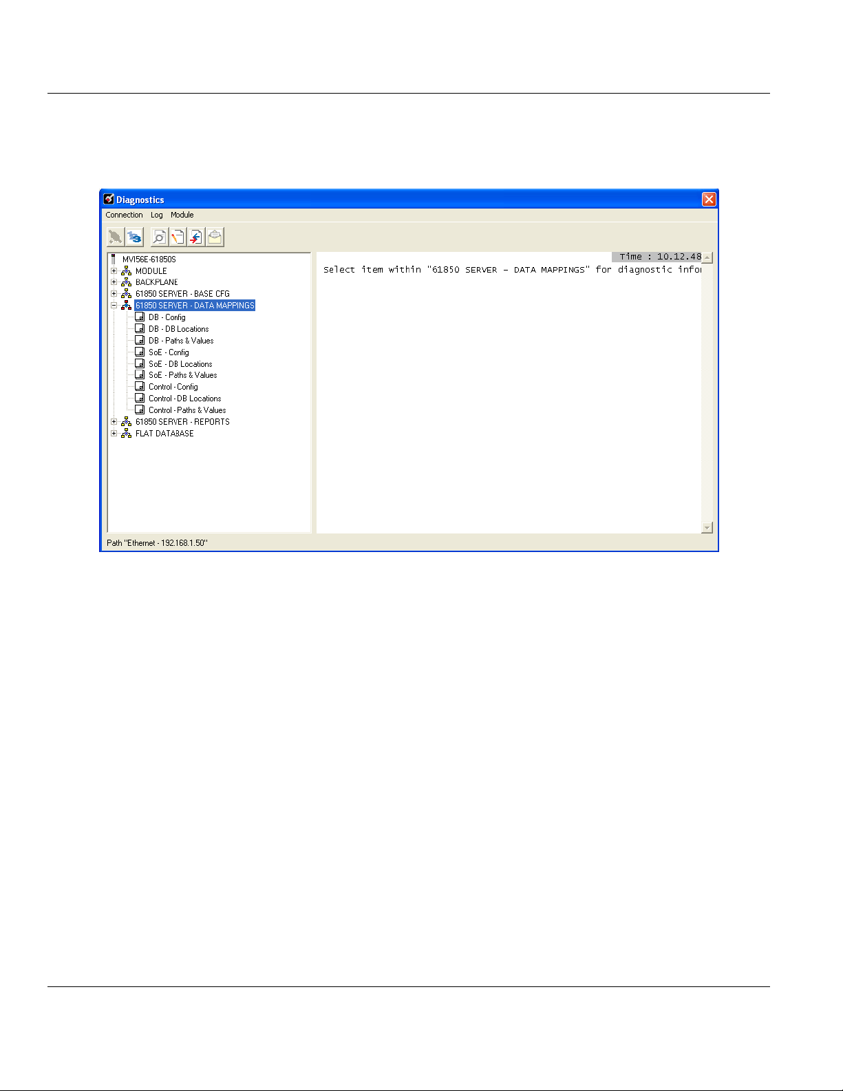
MVI56E-61850S ♦ ControlLogix Platform Contents
IEC 61850 Server Communication Module User Manual
6.4.4 Monitoring Data Mappings Information
Use the 61850 SERVER - DATA MAPPINGS selection to view the configured data
mappings of each Data Object for the MVI56E-61850S module.
ProSoft Technology, Inc. Page 75 of 81
September 4, 2014
Page 76

Contents MVI56E-61850S ♦ ControlLogix Platform
User Manual IEC 61850 Server Communication Module
6.4.5 Monitoring Backplane Information
Use the 61850 SERVER - REPORTS selection to view the 61850 protocol report
configurations for the MVI56E-61850S module.
Page 76 of 81 ProSoft Technology, Inc.
September 4, 2014
Page 77

MVI56E-61850S ♦ ControlLogix Platform Contents
IEC 61850 Server Communication Module User Manual
6.4.6 Monitoring Flat Database Information
Use the FLAT DATABASE selection to view the raw data values that currently populate the
MVI56E-61850S module memory.
ProSoft Technology, Inc. Page 77 of 81
September 4, 2014
Page 78

Contents MVI56E-61850S ♦ ControlLogix Platform
User Manual IEC 61850 Server Communication Module
6.5 Connect to the Module’s Web Page
The module's internal web server provides access to module status, diagnostics, and
firmware updates. If the module's IP address has already been assigned, simply enter in the
IP address into a web browser. If not, follow the steps below:
1 In ProSoft Configuration Builder, click the PROJECT menu, then choose MODULE >
DOWNLOAD FROM PC TO DEVICE. This opens the Download dialog box.
2 In the Download dialog box, choose the connection type in the Select Connection Type
dropdown box:
o Choose ETHERNET if you are connecting to the module through the Ethernet cable.
o Choose 1756 ENBT if you are connecting through CIPconnect or RSWho.
Refer to Connecting Your PC to the Module for more information.
3 In the Download files from PC to module dialog box, click BROWSE DEVICE(S).
4 In ProSoft Discovery Service, right-click the MVI56E-61850S icon and choose VIEW
MODULE’S WEBPAGE from the shortcut menu.
This displays the module webpage.
Page 78 of 81 ProSoft Technology, Inc.
September 4, 2014
Page 79

MVI56E-61850S ♦ ControlLogix Platform Contents
In This Chapter
Contacting Technical Support ................................................................79
Warranty Information .............................................................................80
IEC 61850 Server Communication Module User Manual
7 Support, Service & Warranty
7.1 Contacting Technical Support
ProSoft Technology, Inc. is committed to providing the most efficient and effective support
possible. Before calling, please gather the following information to assist in expediting this
process:
1 Product Version Number
2 System architecture
3 Network details
If the issue is hardware related, we will also need information regarding:
1 Module configuration and associated ladder files, if any
2 Module operation and any unusual behavior
3 Configuration/Debug status information
4 LED patterns
5 Details about the serial, Ethernet or Fieldbus devices interfaced to the module, if any.
Note: For technical support calls within the United States, an emergency after-hours answering system allows
24-hour/7-days-a-week pager access to one of our qualified Technical and/or Application Support Engineers.
Detailed contact information for all our worldwide locations is available on the following page.
ProSoft Technology, Inc. Page 79 of 81
September 4, 2014
Page 80

Contents MVI56E-61850S ♦ ControlLogix Platform
Internet
Web Site: www.prosoft-technology.com/support
E-mail address: support@prosoft-technology.com
Asia Pacific
(location in Malaysia)
Tel: +603.7724.2080
E-mail: asiapc@prosoft-technology.com
Languages spoken include: Chinese, English
Asia Pacific
(location in China)
Tel: +86.21.5187.7337 x888
E-mail: asiapc@prosoft-technology.com
Languages spoken include: Chinese, English
Europe
(location in Toulouse,
France)
Tel: +33 (0) 5.34.36.87.20
E-mail: support.EMEA@prosoft-technology.com
Languages spoken include: French, English
Europe
(location in Dubai, UAE)
Tel: +971-4-214-6911
E-mail: mea@prosoft-technology.com
Languages spoken include: English, Hindi
North America
(location in California)
Tel: +1.661.716.5100
E-mail: support@prosoft-technology.com
Languages spoken include: English, Spanish
Latin America
(Oficina Regional)
Tel: +1-281-2989109
E-Mail: latinam@prosoft-technology.com
Languages spoken include: Spanish, English
Latin America
(location in Puebla, Mexico)
Tel: +52-222-3-99-6565
E-mail: soporte@prosoft-technology.com
Languages spoken include: Spanish
Brasil
(location in Sao Paulo)
Tel: +55-11-5083-3776
E-mail: brasil@prosoft-technology.com
Languages spoken include: Portuguese, English
User Manual IEC 61850 Server Communication Module
7.2 Warranty Information
For complete details regarding ProSoft Technology’s TERMS & CONDITIONS OF SALE,
WARRANTY, SUPPORT, SERVICE AND RETURN MATERIAL AUTHORIZATION
INSTRUCTIONS please see the documents on the Product DVD or go to www.prosoft-
technology/warranty.
Documentation is subject to change without notice.
Page 80 of 81 ProSoft Technology, Inc.
September 4, 2014
Page 81

MVI56E-61850S ♦ ControlLogix Platform Support, Service & Warranty
IEC 61850 Server Communication Module User Manual
Monitoring Data Mappings Information • 75
Monitoring Flat Database Information • 77
Monitoring Module Information • 72
Index
6
61850S BR0x Dataset • 36
61850S Buffered Reports • 34
61850S Controller Tag Overview • 49
61850S Data Control • 32
61850S Data DB Configuration • 28
61850S Data SoE • 30
61850S Identification • 24
61850S IP Filter • 26
61850S Network • 25
61850S Unbuffered Reports • 38
61850S UR0x Dataset • 40
B
Backplane Configuration • 22
C
Clearing a Fault Condition • 67
Configuring the RSLinx Driver for the PC COM Port •
14
Connect to the Module’s Web Page • 66, 78
Connecting Your PC to the ControlLogix Processor •
12
Connecting Your PC to the Module's Ethernet Port •
42, 44
Contacting Technical Support • 79
Content Disclaimer • 2
Control Example • 62
D
Data DB Example • 53
Diagnostics and Troubleshooting • 65, 66
Downloading the Project to the Module • 42
Downloading the Sample Program to the Processor •
13, 55, 58, 63
MVI56E-61850S Configuration • 21
MVI56E-61850S Controller Tags • 49
MVI56E-61850S User-Defined Data Types • 49
MVI56E61850S.COMMAND • 51
MVI56E61850S.DATA • 50
MVI56E61850S.STATUS Tag • 52
MVI56E61850S.UTIL Tag • 52
N
Non-Scrolling LED Status Indicators • 67
P
Package Contents • 9
R
RSLogix 5000 Configuration • 49
S
Scrolling LED Status Indicators • 66
Setting Jumpers • 9
Setting Up a Temporary IP Address • 44
Setting Up ProSoft Configuration Builder • 17
Setting Up the Project • 18
SoE Example • 58
Start Here • 7
Support, Service & Warranty • 79
System Requirements • 8
T
Troubleshooting • 68
U
Using RSWho to Connect to the Module • 47
Using the Diagnostics Menu in ProSoft Configuration
Builder • 69
W
Warranty Information • 80
E
Ethernet LED Indicators • 65
Ethernet1 • 23
Examples • 50, 53
Your Feedback Please • 2
Y
I
Important Safety Information • 3
Installing ProSoft Configuration Builder • 17
Installing the Module in the Rack • 10
M
Monitoring Backplane Information • 73, 76
Monitoring Base Configuration Information • 74
ProSoft Technology, Inc. Page 81 of 81
September 4, 2014
 Loading...