

Page 1
MVI56-AFC
ControlLogix Platform
Liquid and Gas Flow Computer
February 25, 2011
USER MANUAL
Page 2

Your Feedback Please
We always want you to feel that you made the right decision to use our products. If you have suggestions, comments,
compliments or complaints about our products, documentation, or support, please write or call us.
How to Contact Us
ProSoft Technology
5201 Truxtun Ave., 3rd Floor
Bakersfield, CA 93309
+1 (661) 716-5100
+1 (661) 716-5101 (Fax)
www.prosoft-technology.com
support@prosoft-technology.com
Copyright © 2011 ProSoft Technology, Inc., all rights reserved.
MVI56-AFC User Manual
February 25, 2011
ProSoft Technology ®, ProLinx ®, inRAx ®, ProTalk ®, and RadioLinx ® are Registered Trademarks of ProSoft
Technology, Inc. All other brand or product names are or may be trademarks of, and are used to identify products
and services of, their respective owners.
ProSoft Technology® Product Documentation
In an effort to conserve paper, ProSoft Technology no longer includes printed manuals with our product shipments.
User Manuals, Datasheets, Sample Ladder Files, and Configuration Files are provided on the enclosed CD-ROM,
and are available at no charge from our web site: www.prosoft-technology.com
Page 3

Important Installation Instructions
Power, Input, and Output (I/O) wiring must be in accordance with Class I, Division 2 wiring methods, Article 501-4 (b)
of the National Electrical Code, NFPA 70 for installation in the U.S., or as specified in Section 18-1J2 of the Canadian
Electrical Code for installations in Canada, and in accordance with the authority having jurisdiction. The following
warnings must be heeded:
A WARNING - EXPLOSION HAZARD - SUBSTITUTION OF COMPONENTS MAY IMPAIR SUITABILITY FOR
CLASS I, DIV. 2;
B WARNING - EXPLOSION HAZARD - WHEN IN HAZARDOUS LOCATIONS, TURN OFF POWER BEFORE
REPLACING OR WIRING MODULES
C WARNING - EXPLOSION HAZARD - DO NOT DISCONNECT EQUIPMENT UNLESS POWER HAS BEEN
SWITCHED OFF OR THE AREA IS KNOWN TO BE NON-HAZARDOUS.
D THIS DEVICE SHALL BE POWERED BY CLASS 2 OUTPUTS ONLY.
MVI (Multi Vendor Interface) Modules
WARNING - EXPLOSION HAZARD - DO NOT DISCONNECT EQUIPMENT UNLESS POWER HAS BEEN
SWITCHED OFF OR THE AREA IS KNOWN TO BE NON-HAZARDOUS.
AVERTISSEMENT - RISQUE D'EXPLOSION - AVANT DE DÉCONNECTER L'ÉQUIPEMENT, COUPER LE
COURANT OU S'ASSURER QUE L'EMPLACEMENT EST DÉSIGNÉ NON DANGEREUX.
Warnings
North America Warnings
Power, Input, and Output (I/O) wiring must be in accordance with Class I, Division 2 wiring methods, Article 501-4 (b)
of the National Electrical Code, NFPA 70 for installation in the U.S., or as specified in Section 18-1J2 of the Canadian
Electrical Code for installations in Canada, and in accordance with the authority having jurisdiction. The following
warnings must be heeded:
A Warning - Explosion Hazard - Substitution of components may impair suitability for Class I, Division 2.
B Warning - Explosion Hazard - When in hazardous locations, turn off power before replacing or rewiring modules.
C Warning - Explosion Hazard - Do not disconnect equipment unless power has been switched off or the area is
known to be non-hazardous.
Avertissement - Risque d'explosion - Avant de déconnecter l'équipement, couper le courant
ou s'assurer que l'emplacement est désigné non dangereux.
D Suitable for use in Class I, Division 2 Groups A, B, C and D Hazardous Locations or Non-Hazardous Locations.
ATEX Warnings and Conditions of Safe Usage
Power, Input, and Output (I/O) wiring must be in accordance with the authority having jurisdiction.
A Warning - Explosion Hazard - When in hazardous locations, turn off power before replacing or wiring modules.
B Warning - Explosion Hazard - Do not disconnect equipment unless power has been switched off or the area is
known to be non-hazardous.
C These products are intended to be mounted in an IP54 enclosure. The devices shall provide external means to
prevent the rated voltage being exceeded by transient disturbances of more than 40%. This device must be used
only with ATEX certified backplanes.
D DO NOT OPEN WHEN ENERGIZED.
Battery Life Advisory
The MVI46, MVI56, MVI56E, MVI69, and MVI71 modules use a rechargeable Lithium Vanadium Pentoxide battery to
backup the real-time clock and CMOS. The battery should last for the life of the module. The module must be
powered for approximately twenty hours before the battery becomes fully charged. After it is fully charged, the battery
provides backup power for the CMOS setup and the real-time clock for approximately 21 days. When the battery is
fully discharged, the module will revert to the default BIOS and clock settings.
Note: The battery is not user replaceable.
Page 4
Markings
Electrical Ratings
Backplane Current Load: 800 mA @ 5.1 Vdc; 3 mA @ 24 Vdc
Operating Temperature: 0°C to 60°C (32°F to 140°F)
Storage Temperature: -40°C to 85°C (-40°F to 185°F)
Shock: 30 g, operational; 50 g, non-operational; Vibration: 5 g from 10 Hz to 150 Hz
Relative Humidity: 5% to 95% with no condensation
All phase conductor sizes must be at least 1.3 mm(squared) and all earth ground conductors must be at least
4mm(squared).
Label Markings
ATEX
II 3 G
EEx nA IIC T6
0°C <= Ta <= 60°C
cULus
E183151
Class I Div 2 Groups A,B,C,D
T6
-30°C <= Ta <= 60°C
Agency Approvals and Certifications
Agency Applicable Standard
RoHS
CE EMC-EN61326-1:2006; EN61000-6-4:2007
ATEX EN60079-15:2003
cULus UL508; UL1604; CSA 22.2 No. 142 & 213
CB Safety CA/10533/CSA
IEC 61010-1 Ed.2; CB 243333-2056722 (2090408)
GOST-R EN 61010
CSA EN 61010
243333
ME06
E183151
Page 5

MVI56-AFC ♦ ControlLogix Platform Contents
Liquid and Gas Flow Computer User Manual
Contents
Your Feedback Please ........................................................................................................................ 2
How to Contact Us .............................................................................................................................. 2
ProSoft Technology® Product Documentation .................................................................................... 2
Important Installation Instructions ....................................................................................................... 3
MVI (Multi Vendor Interface) Modules ................................................................................................ 3
Warnings ............................................................................................................................................. 3
Battery Life Advisory ........................................................................................................................... 3
Markings .............................................................................................................................................. 4
1 Introduction 11
1.1
1.2
1.3
Update Notice .......................................................................................................... 12
MVI56-AFC Module ................................................................................................. 14
Configuration Modification Lockout and Seal .......................................................... 15
2 Quick Start 17
2.1
2.2
2.3
2.4
2.5
2.6
2.1.1
2.3.1
2.3.2
2.3.3
2.3.4
2.3.5
2.3.6
2.3.7
Install AFC Manager ................................................................................................ 18
System Requirements ............................................................................................. 18
Starting AFC Manager ............................................................................................. 19
Using AFC Manager ................................................................................................ 20
Starting a New Project ............................................................................................. 20
Loading an Existing project ..................................................................................... 21
Printing the Configuration Report ............................................................................ 21
Converting a Project ................................................................................................ 22
Resetting Configuration Parameters ....................................................................... 23
Downloading the Project to the Module .................................................................. 24
Verifying Correct Operation ..................................................................................... 25
Ladder Logic Implementation .................................................................................. 26
Setting the Wallclock ............................................................................................... 28
Module Initialization ................................................................................................. 29
3 Meter Channel Functionality 31
3.1
3.2
3.2.1
3.2.2
3.3
3.3.1
3.3.2
3.4
3.5
3.5.1
3.5.2
3.5.3
3.5.4
3.6
3.6.1
Meter Channels ....................................................................................................... 32
Linear (Pulse) Meter Overview ................................................................................ 33
Primary Input = Pulse Count ................................................................................... 33
Primary Input = Pulse Frequency ............................................................................ 33
Differential (Orifice) Meter Overview ....................................................................... 34
Primary Input = Differential Pressure ...................................................................... 34
Primary Input = Flow Rate ....................................................................................... 34
Gas Product Overview ............................................................................................ 35
Liquid Product Overview ......................................................................................... 36
To use a densitometer ............................................................................................. 36
Module Configuration .............................................................................................. 36
Density Units ........................................................................................................... 36
Measuring Water Diluent ......................................................................................... 36
General Features .................................................................................................... 37
Process Variable Interface ...................................................................................... 37
ProSoft Technology, Inc. Page 5 of 316
February 25, 2011
Page 6

Contents MVI56-AFC ♦ ControlLogix Platform
User Manual Liquid and Gas Flow Computer
3.6.2
3.6.3
3.6.4
3.6.5
3.6.6
3.6.7
3.6.8
Meter Scan Time..................................................................................................... 37
Multiple Meter Accumulators .................................................................................. 37
Product Batching .................................................................................................... 37
Data Archiving......................................................................................................... 38
Event Log Function ................................................................................................. 38
Measurement Units ................................................................................................. 38
Process Input Scaling ............................................................................................. 39
4 Meter Proving 41
4.1
4.2
4.3
4.4
4.1.1
4.1.2
4.1.3
4.1.4
4.1.5
4.2.1
4.2.2
4.2.3
4.4.1
4.4.2
Prover Configuration ............................................................................................... 42
Prover Type ............................................................................................................ 42
Prover Options ........................................................................................................ 46
Run Counts ............................................................................................................. 47
Run Input Setup ...................................................................................................... 47
Prover Characteristics ............................................................................................ 49
Setting up the AFC module for Meter Proving ........................................................ 51
Initial Requirements ................................................................................................ 53
Meter Proving Alarms ............................................................................................. 54
Prover Operation (How to do a Prove) ................................................................... 57
Meter Proving Reports ............................................................................................ 63
Protected Meter Proving Data in the AFC's Input Register Bank ........................... 64
Latest Prove Results ............................................................................................... 64
Meter Previous Prove Summary ............................................................................. 67
5 Modbus Database 69
5.1
5.2
5.3
5.1.1
5.2.1
5.2.2
5.2.3
5.2.4
5.3.1
AFC Modbus Address Space ................................................................................. 70
Accessing the Data ................................................................................................. 70
Primary Slave.......................................................................................................... 71
Modbus Address References ................................................................................. 71
Modbus Address Examples .................................................................................... 71
Meter-relative Data ................................................................................................. 72
Scratchpad .............................................................................................................. 73
Virtual Slave ............................................................................................................ 74
Virtual Slave Example Application .......................................................................... 75
6 Modbus Communication 77
6.1
6.2
6.3
6.4
6.3.1
Communication Parameters ................................................................................... 78
Port Options ............................................................................................................ 79
Modbus Master ....................................................................................................... 80
Example .................................................................................................................. 81
Modbus Pass-Through ........................................................................................... 82
7 Accumulators 83
7.1
7.2
7.2.1
7.2.2
7.2.3
Accumulator Totalizer and Residue ........................................................................ 84
Accumulator Types ................................................................................................. 85
Non-Resettable Accumulators ................................................................................ 85
Resettable Accumulators ........................................................................................ 85
Archive Accumulators ............................................................................................. 88
Page 6 of 316 ProSoft Technology, Inc.
February 25, 2011
Page 7

MVI56-AFC ♦ ControlLogix Platform Contents
Liquid and Gas Flow Computer User Manual
7.3
7.4
Net Accumulator Calculation ................................................................................... 89
Frequently Asked Questions ................................................................................... 90
8 Archives 91
8.1
8.2
8.3
8.4
8.5
8.6
8.7
8.8
8.9
8.10
8.8.1
Archive Overview .................................................................................................... 92
Archive Generation .................................................................................................. 93
Archive Types .......................................................................................................... 94
Archive Order .......................................................................................................... 95
Archive Options ....................................................................................................... 97
Archive Locations .................................................................................................... 98
Editing the Archive Structure ................................................................................. 100
Extended Archives ................................................................................................ 102
Retrieving Extended Archives ............................................................................... 102
Archive Reports ..................................................................................................... 105
Archive Monitor ..................................................................................................... 107
9 Events 113
9.1
9.2
9.3
9.4
9.5
9.6
9.7
9.8
9.9
9.10
9.11
9.12
9.13
9.14
9.5.1
9.5.2
9.5.3
9.5.4
9.5.5
9.5.6
9.5.7
9.5.8
The Event Log ....................................................................................................... 114
Event Log Structures ............................................................................................. 115
Event Id Tag .......................................................................................................... 116
Event-triggered Archives and Accumulator Resets .............................................. 117
Downloading the Event Log in Firmware Version 2.07 and Later ......................... 118
Basic Principles of Implementation ....................................................................... 125
Data Elements ....................................................................................................... 127
Virtual Slave Precedence Relations ...................................................................... 129
Security and Optimization ..................................................................................... 130
The Log-Download Window (LDW) ....................................................................... 131
Modbus Transaction Sequencing and Constraints ............................................... 132
Access by Multiple Hosts ...................................................................................... 137
Other Considerations ............................................................................................ 138
Period-end Events ................................................................................................. 139
Loggable Events .................................................................................................... 140
Special Events ....................................................................................................... 141
Site Data Point Events .......................................................................................... 142
Meter Data Point Events ....................................................................................... 143
Stream Data Point Events ..................................................................................... 146
Prover Data Point Events ...................................................................................... 148
"Rkv" Notes ........................................................................................................... 151
Downloading the Event Log in Firmware Version 2.05 and Earlier ...................... 152
10 Security (Passwords) 155
10.1
Hard Password ...................................................................................................... 157
11 MVI56-AFC Backplane Communication 159
11.1
11.1.1
11.1.2
11.2
MVI56-AFC Module Data Transfer ........................................................................ 160
Input/Output Blocks for Data Transfer ................................................................... 160
Input/Output Transactions ..................................................................................... 162
MVI56-AFC Function Block Interface .................................................................... 167
ProSoft Technology, Inc. Page 7 of 316
February 25, 2011
Page 8

Contents MVI56-AFC ♦ ControlLogix Platform
User Manual Liquid and Gas Flow Computer
11.2.1 Function Block Structure .......................................................................................
11.2.2 Function Block Definition - 0: Null ......................................................................... 171
11.2.3 Function Block Definition - 1: Wall Clock .............................................................. 172
11.2.4 Function Block Definition - 4, 5, 6 & 7: Modbus Pass Through ............................ 173
11.2.5 Function Block Definition - 8: Meter Process Variables........................................ 175
11.2.6 Function Block Definition - 9: Meter Analysis, 16-bit ............................................ 184
11.2.7 Function Block Definition - 10: Meter Type Fetch ................................................. 186
11.2.8 Function Block Definition - 11: Meter Analysis, 32-bi
11.2.9 Function Block Definition - 12: Site/Meter Signals ................................................ 190
11.2.10 Function Block Definition - 14: Meter Archive Fetch............................................. 192
11.2.11 Function Block Definition - 16/17/18/19: Modbus Gateway Read ........................ 193
11.2.12 Function Block Definition - 20, 21: Modbus Gateway Write ................................. 196
11.2.13 Function Block Definition - 24, 25, 26: Modbus Master ........................................ 199
11.2.14 Function Block Definition - 28, 29: Disable/Enable Meters .................................. 203
t .......................................... 187
168
12 MVI56-AFC Sample Logic 205
12.1 Sample Logic Overview ........................................................................................ 206
12.1.1 Process Block (uses Transaction Numbers from 1 to 16) .................................... 208
12.1.2 Modbus Gateway Block (uses Transaction Numbers from 17 to 25) ................... 209
12.1.3 Wallclock Block (uses Transaction Number =99) ................................................. 209
12.1.4 Sample MVI56-AFC Logic Tasks.......................................................................... 210
12.2 Using the Sample Add-On Instruction .................................................................. 211
12.2.1 Import Procedure .................................................................................................. 211
12.3 ControlLogix Sample Logic Details ....................................................................... 220
12.3.1 Enable/Disable Status .......................................................................................... 220
12.3.2 Disable Meter ........................................................................................................ 220
12.3.3 Enable Meter......................................................................................................... 221
12.3.4 Wallclock ............................................................................................................... 222
12.3.5 Meter Profile .......................................................................................................... 223
12.3.6 Meter Process Variables ....................................................................................... 224
12.3.7 Meter Calculation Results ..................................................................................... 227
12.3.8 Meter Signals ........................................................................................................ 229
12.3.9 Molar Analysis (For Gas Product Only) ................................................................ 231
12.3.10 Set the Processor Time ........................................................................................ 236
12.3.11 Checking Meter Alarms ........................................................................................ 237
12.3.12 Site Status ............................................................................................................. 239
12.3.13 Modbus Master ..................................................................................................... 239
12.3.14 Modbus pass-through ........................................................................................... 244
12.3.15 Modbus Gateway .................................................................................................. 245
13 Diagnostics and Troubleshooting 255
13.1 User LEDs ............................................................................................................. 256
13.1.1 App Status LED .................................................................................................... 256
13.1.2 BP Act and P1, P2, or P3 ..................................................................................... 256
13.2 BBRAM LEDs ....................................................................................................... 257
13.3 Meter Alarms ......................................................................................................... 258
13.4 Checksum Alarms ................................................................................................. 262
13.5 Events ...................................................................................................................
13.6 Audit Scan ............................................................................................................. 264
263
Page 8 of 316 Pr
oSoft Technology, Inc.
February 25, 2011
Page 9

MVI56-AFC ♦ ControlLogix Platform Contents
Liquid and Gas Flow Computer User Manual
14 Reference 269
14.1 General Specifications .......................................................................................... 270
14.1.1 On-line Communication & Configuration ............................................................... 271
14.1.2 Reports .................................................................................................................. 271
14.1.3 Modbus Interface ................................................................................................... 271
14.1.4 Configurable Options ............................................................................................. 272
14.1.5 Supported Meters ...................................
14.1.6 Hardware Specifications........................................................................................ 273
14.2 Measurement Standards ....................................................................................... 274
14.2.1 Basic Metering According to Meter type ............................................................... 275
14.2.2 Liquid Correction Factor Details ............................................................................ 277
14.3 Wedge Meter Applications .................................................................................... 279
14.4 Configurable Archive Registers ............................................................................. 280
14.4.1 Information for Users of AFC Manager Versions Older Than 2.01.000 ................ 284
14.5 Archive Data Format ............................................................................................. 286
14.5.1 Timestamp Date and Time Format ....................................................................... 286
14.5.2 Pre-defined Header ............................................................................................... 287
14.5.3 Orifice (Differential) Meter with Gas Product......................................................... 288
14.5.4 Pulse (Linear) Meter with Gas Product ................................................................. 289
14.5.5 Orifice (Differential) Meter with Liquid Product...................................................... 289
14.5.6 Pulse (Linear) Meter with Liquid Product .............................................................. 290
14.5.7 Flow Rate Integration with Gas Product ................................................................ 290
14.5.8 Pulse Frequency Integration with Gas Product ..................................................... 291
14.5.9 Flow Rate Integration with Liquid Product............................................................. 291
14.5.10 Pulse Frequency Integration with Liquid Product .................................................. 292
14.6 Modbus Addressing Common to Both Primary and Virtual Slaves ....................... 293
14.7 Modbus Port configuration .................................................................................... 296
14.8 Startup Basics and Frequently Asked Questions .................................................. 298
14.9 Cable Connections ..................................
14.9.1 RS-232 Configuration/Debug Port ........................................................................ 299
14.9.2 RS-232 Application Port(s) ................................................................................... 299
14.9.3 RS-422 .................................................................................................................. 302
14.9.4 RS-485 Application Port(s) .................................................................................... 302
14.9.5 DB9 to RJ45 Adaptor (Cable 14) .......................................................................... 303
............................................................... 272
.............................................................. 299
15 Support, Service & Warranty 305
Contacting Technical Support ......................................................................................................... 305
15.1 Return Material Authorization (RMA) Policies and Conditions.............................. 307
15.1.1 Returning Any Product .......................................................................................... 307
15.1.2 Returning Units Under Warranty ........................................................................... 308
15.1.3 Returning Units Out of Warranty ........................................................................... 308
15.2 LIMITED WARRANTY ........................................................................................... 309
15.2.1 What Is Covered By This Warranty ....................................................................... 309
15.2.2 What Is Not Covered By This Warranty ................................................................ 310
15.2.3 Disclaimer Regarding High Risk Activities ............................................................ 310
15.2.4 Intellectual Property Indemnity .............................................................................. 311
15.2.5 Disclaimer of all Other Warranties ........................................................................ 311
15.2.6 Limitation of Remedies ** ...................................................................................... 312
15.2.7 Time Limit for Bringing Suit ................................................................................... 312
15.2.8 No Other Warranties ................................
15.2.9 Allocation of Risks ................................................................................................. 312
............................................................. 312
ProSoft Technology, Inc. P
February 25, 2011
age 9 of 316
Page 10

Contents MVI56-AFC ♦ ControlLogix Platform
User Manual Liquid and Gas Flow Computer
15.2.10
Controlling Law and Severability .......................................................................... 312
Index 313
Page 10 of 316 ProSoft Technology, Inc.
February 25, 2011
Page 11

MVI56-AFC ♦ ControlLogix Platform Introduction
Liquid and Gas Flow Computer User Manual
1 Introduction
In This Chapter
Update Notice ........................................................................................ 12
MVI56-AFC Module ............................................................................... 14
Configuration Modification Lockout and Seal ........................................ 15
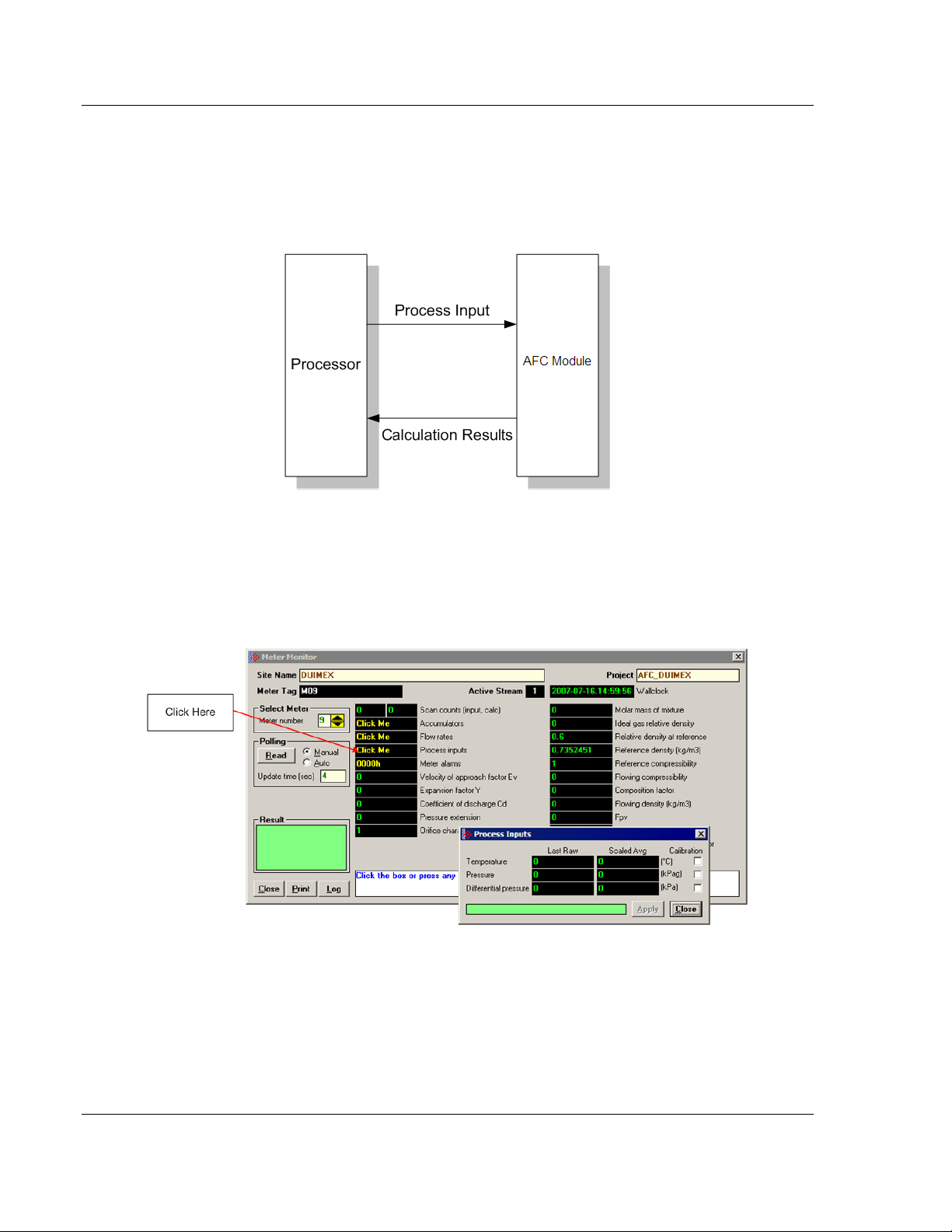
The MVI56-AFC Flow Computer module performs measurement of hydrocarbon
gases and liquids using currently accepted industry measurement standards. The
module consists of a single-slot solution for Rockwell Automation chassis. To
obtain its process inputs for calculations, the module uses the process data
collected by analog and pulse I/O modules. The processor transfers this data to
the AFC module, which then calculates flow rates, accumulated volumes, and
accumulated mass. The results of the calculations are transferred back to the
processor for use in the application logic, or for transfer to a SCADA host.
The module has two communication ports for Modbus communication allowing
easy access to a remote Modbus device. The module works as a Modbus slave
or master device.
As discussed later in this manual, the internal Modbus database can be
accessed by a Modbus Master device and by the processor (using the Modbus
Gateway Function).
The AFC Manager software can be used for easy meter configuration and
application monitoring. Refer to the AFC Manager User Manual for complete
information about this tool.
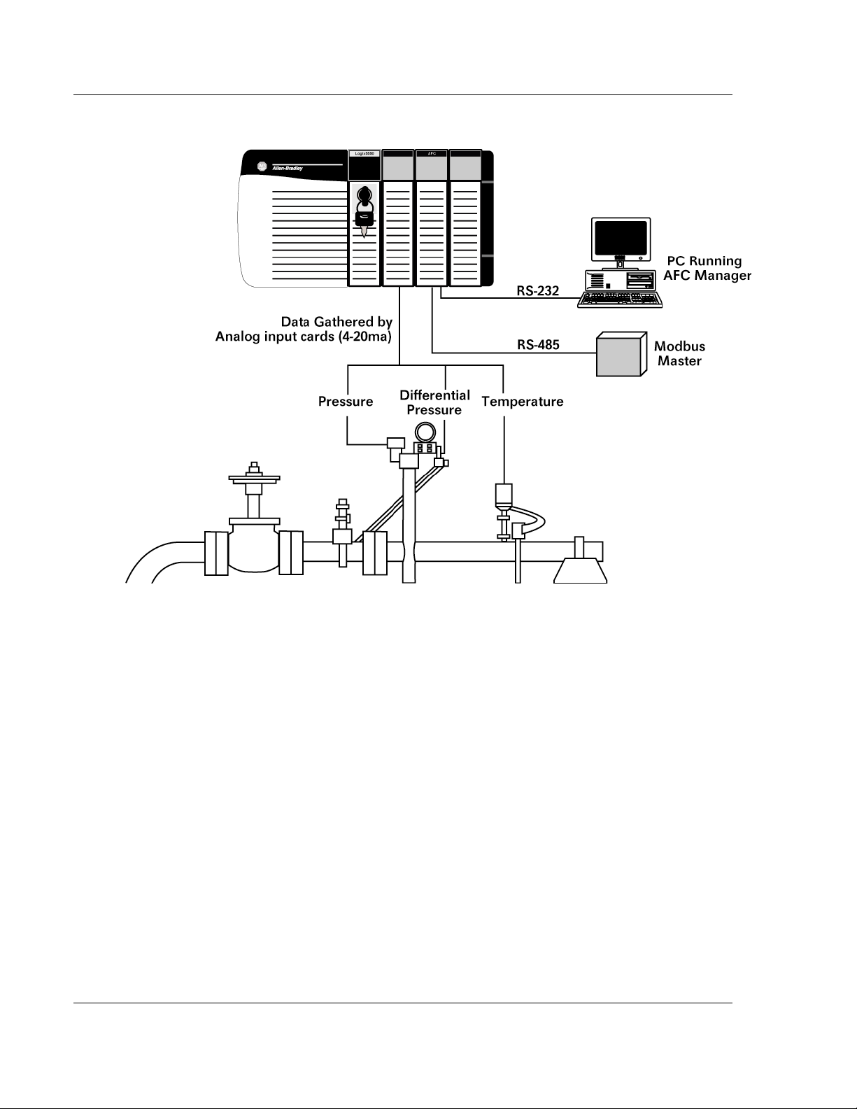
The following section provides a sample application where input data is
transferred from the transmitters to analog input cards on the Rockwell
Automation rack and the values are transferred from the processor to the module
(the module supports floating-point, scaled integer, or 4 to 20 mA format).
For Pulse meter applications, the pulse count and pulse frequency values are
typically transmitted through high-speed counter modules in the rack.
The module performs the flow calculation based on the values transferred
through the backplane. The calculation results can be read to the processor or
polled from a remote Modbus master unit connected to one of the communication
ports.
ProSoft Technology, Inc. Page 11 of 316
February 25, 2011
Page 12

Introduction MVI56-AFC ♦ ControlLogix Platform
User Manual Liquid and Gas Flow Computer
1.1 Update Notice
If your module measures liquids, please read this notice before upgrading from
version 2.04 (or earlier) to 2.05 (or later).
For compliance with new measurement standards, the AFC version 2.05 has
introduced several new liquid product groups. In particular, the two non-refined
liquid product groups of version 2.04, which covered the entire density range of
crudes and NGLs, have each been split into two separate product groups, one
for the higher density range of crudes and the other for the lower density range of
NGLs. If your module has meter channels configured for either "Crude, NGL" or
"Oil-water emulsion", you should decide before upgrading the firmware the
new product group (light or heavy) to which each such channel should be
assigned. This assignment will be performed during the upgrade process and will
preserve all other configuration and historical records including accumulator
values and archives, in contrast to changing a product group after the upgrade
which resets the meter configuration and erases all historical records. Meter
channels configured for "Gas" or "Refined products" are not affected.
AFC Manager exhibits the same behavior when converting a project between
versions 2.04 (or earlier) and 2.05 (or later).
The criterion for assigning the new product group depends on the density units
and the Default Reference Density, as described in the following tables:
Density Units = kg/m3
Version 2.04 Product Group Default Reference Density Version 2.05 Product Group
Crude, NGL
Crude, NGL > 0 AND < 610.0 NGLs, LPGs
Oil Water Emulsion
Oil Water Emulsion
= 0 OR ≥ 610.0
= 0 OR ≥ 610.0
> 0 AND < 610.0
Crude oils, JP4
Oil-water emulsion (Crd)
Oil-water emulsion (NGL)
Density Units = Rd/60
Version 2.04 Product Group Default Reference Density Version 2.05 Product Group
Crude, NGL
Crude, NGL > 0 AND < 0.6100 NGLs, LPGs
Oil Water Emulsion
Oil Water Emulsion > 0 AND < 0.6100 Oil-water emulsion (NGL)
= 0 OR ≥ 0.6100
= 0 OR ≥ 0.6100
Crude oils, JP4
Oil-water emulsion (Crd)
Due to roundoff error of numeric conversions, a Relative Density very close to
the cutoff value of 0.6100 may cause the module to assign the new product
group opposite to the one that was intended. Before upgrading, change the
Default Reference Density to a number significantly different from 0.6100, such
as 0.6110 (to target Crude) or 0.6090 (to target NGLs). You may change it back
to the correct value after the upgrade.
Page 12 of 316 ProSoft Technology, Inc.
February 25, 2011
Page 13

MVI56-AFC ♦ ControlLogix Platform Introduction
Liquid and Gas Flow Computer User Manual
Density Units = API Gravity
Version 2.04 Product Group Default Reference Density Version 2.05 Product Group
Crude, NGL
= 0 OR ≤ 100.0
Crude, NGL > 0 AND > 100.0 NGLs, LPGs
Oil Water Emulsion
Oil Water Emulsion > 0 AND > 100.0 Oil-water emulsion (NGL)
= 0 OR ≤ 100.0
Crude oils, JP4
Oil-water emulsion (Crd)
ProSoft Technology, Inc. Page 13 of 316
February 25, 2011
Page 14
Introduction MVI56-AFC ♦ ControlLogix Platform
User Manual Liquid and Gas Flow Computer
1.2 MVI56-AFC Module
Page 14 of 316 P
roSoft Technology, Inc.
February 25, 2011
Page 15
MVI56-AFC ♦ ControlLogix Platform Introduction
Liquid and Gas Flow Computer User Manual
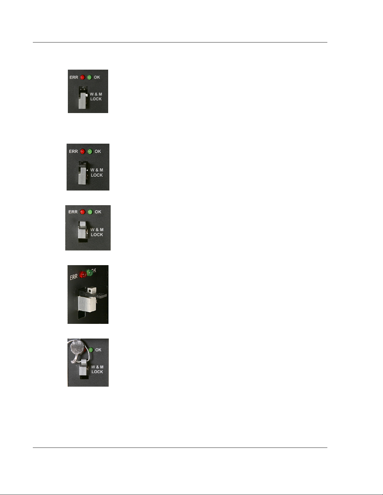
1.3 Configuration Modification Lockout and Seal
The MVI56-AFC application configuration can be certified and sealed with a userinstallable Lockout jumper and a tamper-evident lead seal. The Lockout jumper
and seal are commonly required for Weights & Measures certification, or custody
transfer applications.
Important: When the jumper is installed, the module will not accept configuration changes to
Sealable Parameters, which are parameters that affect the accuracy of flow calculation. Before
breaking the seal to remove the jumper, you should verify the steps required to recertify the module
with the appropriate regulatory agency.
For more information on sealing procedures, refer to "Sealing Provisions", on
page 8 of the MVI56-AFC Custody Transfer Certification document, which is
available from the ProSoft Technology web site at http://www.prosofttechnology.com/content/view/full/4613
ProSoft Technology, Inc. Page 15 of 316
February 25, 2011
Page 16
Introduction MVI56-AFC ♦ ControlLogix Platform
User Manual Liquid and Gas Flow Computer
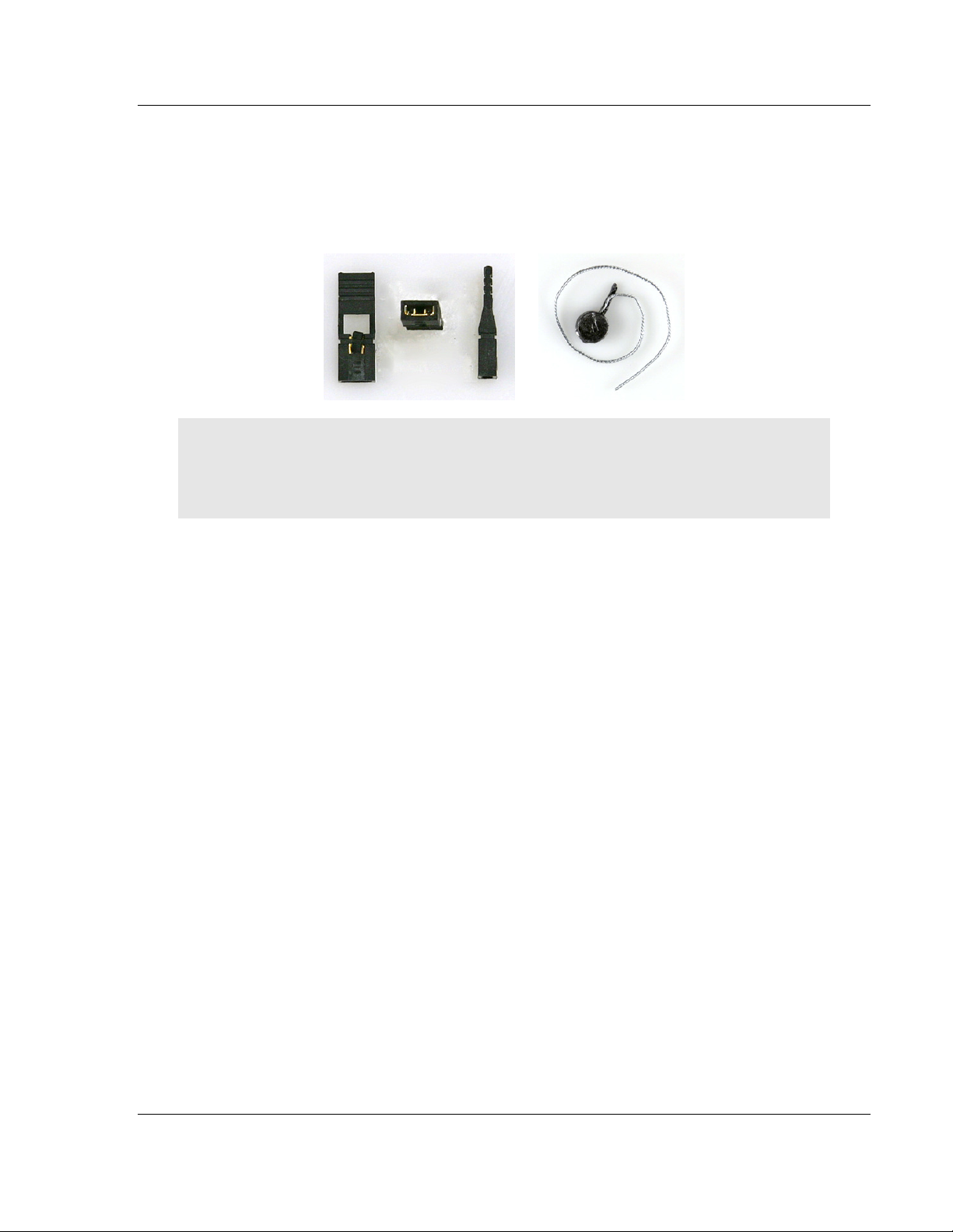
To install the Lockout jumper and seal, follow these steps.
1 Locate the Lockout Jumper pins and Lockout Block,
labeled "W & M Lock" inside the module door, and
below the BBRAM ERR and OK LEDs.
1 Install the provided Lockout Jumper to connect the two
pins.
1 Carefully slide the Lockout Block up through the hole in
the Lockout Jumper. Be careful not to bend or break
the jumper block pins.
1 When the Lockout Block is positioned correctly, it will
expose a hole in the block, through which you may
pass the seal wire.
1 Slide the seal wire through the hole in the Lockout
Block. Pass the wire through the slot in the lead seal,
and then crimp the lead seal around the wire.
Once sealed, the Lockout block and jumper cannot be removed without
damaging the seal, the block, or the jumper.
Page 16 of 316 ProSoft Technology, Inc.
February 25, 2011
Page 17

MVI56-AFC ♦ ControlLogix Platform Quick Start
Liquid and Gas Flow Computer User Manual
2 Quick Start
In This Chapter
Install AFC Manager .............................................................................. 18
Starting AFC Manager ........................................................................... 19
Using AFC Manager .............................................................................. 20
Ladder Logic Implementation ................................................................ 26
Setting the Wallclock ............................................................................. 28
Module Initialization ............................................................................... 29
This section provides a general overview of the steps required to install and
configure the module. You should read the AFC Manager User Manual to obtain
a clear understanding of the steps outlined in this section.
ProSoft Technology, Inc. Page 17 of 316
February 25, 2011
Page 18

Quick Start MVI56-AFC ♦ ControlLogix Platform
User Manual Liquid and Gas Flow Computer
2.1 Install AFC Manager
The AFC Manager application is included on the CD-ROM shipped with your
module. Before you can use the application, you must install it on your computer.
2.1.1 System Requirements
The following system requirements are the recommended minimum
specifications to successfully install and run AFC Manager:
Microsoft Windows compatible PC
Windows 2000 with Service Pack 2 or higher, or Windows XP Professional
with Service Pack 2 or higher, or Windows 2003 or Windows Vista, or
Windows 7.
300 mHz Pentium processor (or equivalent)
128 megabytes of RAM
20 megabytes of free disk space
Available serial port (COM port) or USB to Serial adapter cable with
necessary drivers, required for communication between AFC Manager
software and the AFC module.
DB9 adapter cable (included with module), required for connection between
PC serial port and AFC module (PTQ-AFC module does not require an
adapter).
To install the AFC Manager application
1 Insert the ProSoft Solutions CD in your CD-ROM drive. On most computers,
a menu screen will open automatically. If you do not see a menu within a few
seconds, follow these steps:
a Click the Start button, and then choose Run.
b In the Run dialog box, click the Browse button.
c In the Browse dialog box, click "My Computer". In the list of drives,
choose the CD-ROM drive where you inserted the ProSoft Solutions CD.
d Select the file prosoft.exe, and then click Open.
e On the Run dialog box, click OK.
2 On the CD-ROM menu, click Documentation and Tools. This action opens a
Windows Explorer dialog box.
3 Open the Utilities folder, and then open the AFCManager folder.
4 Double-click the file Setup.exe. If you are prompted to restart your computer
so that files can be updated, close all open applications, and then click OK.
When your computer has finished restarting, begin again at Step 1.
5 Click OK or Yes to dismiss any confirmation dialog boxes.
6 It may take a few seconds for the installation wizard to start. Click OK on the
AFC Manager Setup dialog box to begin installing AFC Manager.
7 Follow the instructions on the installation wizard to install the program with its
default location and settings.
8 When the installation finishes, you may be prompted to restart your computer
if certain files were in use during installation. The updated files will be
installed during the restart process.
Page 18 of 316 ProSoft Technology, Inc.
February 25, 2011
Page 19

MVI56-AFC ♦ ControlLogix Platform Quick Start
Liquid and Gas Flow Computer User Manual
2.2 Starting AFC Manager
To start AFC Manager
1 Click the S
2 In the Programs menu, choose ProSoft Technology.
3 In the ProSoft Technology menu, choose AFC Manager.
TART
button, and then choose P
ROGRAMS
.
ProSoft Technology, Inc. Page 19 of 316
February 25, 2011
Page 20
Quick Start MVI56-AFC ♦ ControlLogix Platform
User Manual Liquid and Gas Flow Computer
2.3 Using AFC Manager
The AFC module is configured with configuration files that you create using AFC
Manager. A configuration file is called a Project.
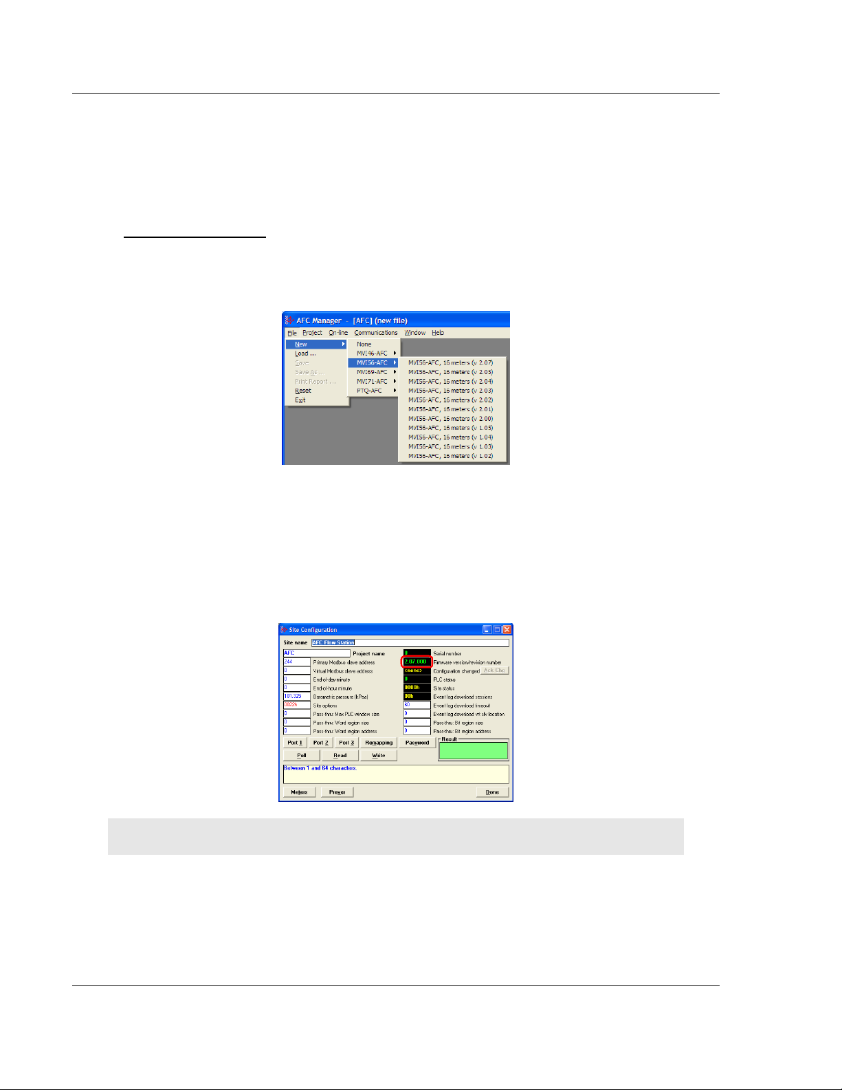
2.3.1 Starting a New Project
To start a new project
1 Start AFC M
2 On the File Menu, choose NEW, and then select your module and firmware
version number.
The version number refers to the firmware version of your module. If you do
not know the firmware version number, follow these steps:
a) Open the Project menu.
b) Choose S
dialog box.
c) Click the R
number, in the upper right part of the dialog box.
ANAGER
ITE CONFIGURATION
EAD
button. The firmware version is listed below the serial
, and then open the File Menu.
. This action opens the Site Configuration
Important: You must be connected to the module and "online" to read data from the module.
3 Follow the steps in the remainder of this User Guide to configure your module
and your AFC device.
4 Before closing the program, open the File menu and choose S
AVE AS
, to
save your project so you can open it again later.
Page 20 of 316 ProSoft Technology, Inc.
February 25, 2011
Page 21
MVI56-AFC ♦ ControlLogix Platform Quick Start
Liquid and Gas Flow Computer User Manual
2.3.2 Loading an Existing project
You can open and edit a project you have previously saved. Do this if you have
started, but not completed, the configuration of your project, or if you need to
modify the settings for a project that has already been downloaded to the
module.
To load an existing project
1 Start AFC M
2 On the File menu, choose L
ANAGER
, and then open the File menu.
OAD
. This action opens a dialog box that shows a
list of AFC Manager project files (AFC files) in the current folder.
3 Choose the project to load, and then click O
PEN
.
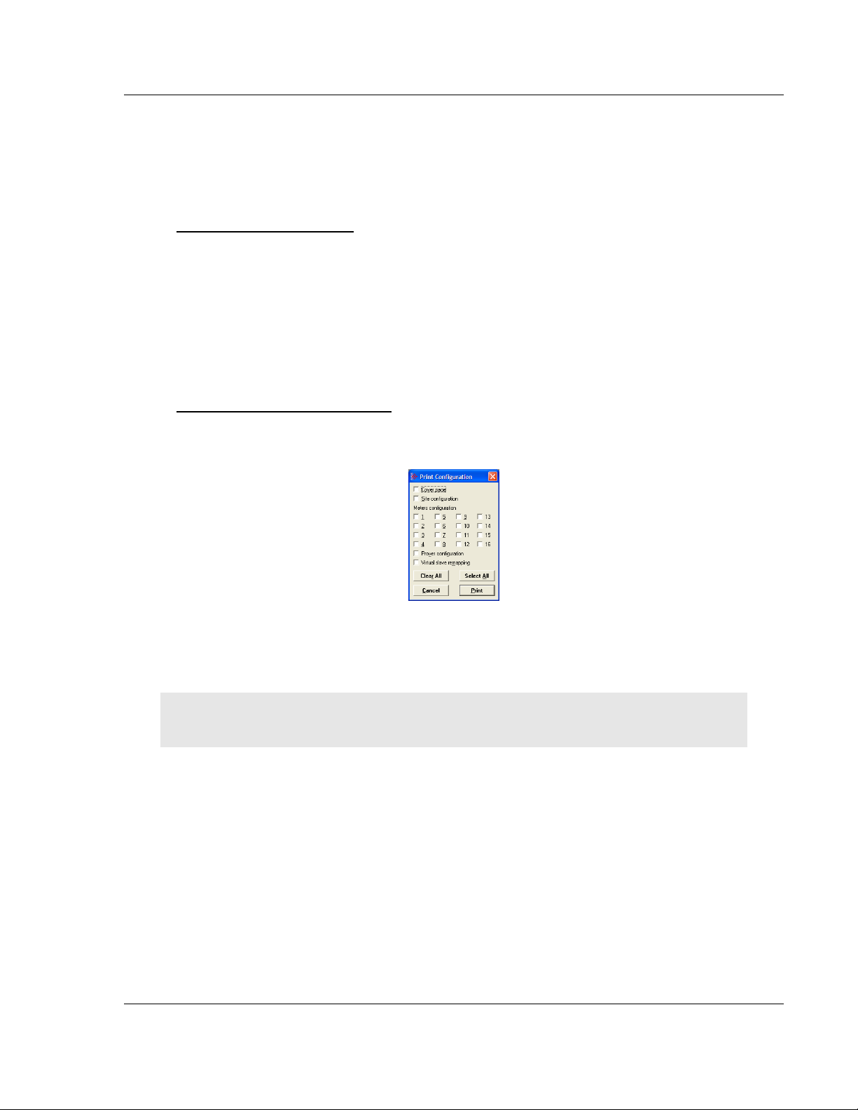
2.3.3 Printing the Configuration Report
You can print a report of your configuration for future reference, or for archival
purposes.
To print the configuration report
1 Open the File menu, and then select P
Print Configuration dialog box.
RINT REPORT
. This action opens the
2 On the Print Configuration dialog box, select (check) the items to include in
the printed report.
3 Click P
RINT
to send the report to your default printer.
Note: The size of the report depends on items you choose to include, and may require 75 pages or
more. Consider this before printing.
ProSoft Technology, Inc. Page 21 of 316
February 25, 2011
Page 22
Quick Start MVI56-AFC ♦ ControlLogix Platform
User Manual Liquid and Gas Flow Computer
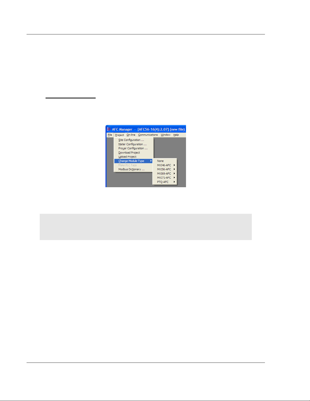
2.3.4 Converting a Project
You can convert an existing project (configuration file) to use it with a different
module or firmware version. Do this if:
You want to reuse an application created for a different AFC module, for
example a project that was created for a PTQ-AFC that you want to use for
an MVI69-AFC.
You apply a firmware upgrade to a module.
To convert a project:
1 Open the File menu, and then choose O
2 Open the project (configuration file) to convert.
3 Open the Project menu, and then choose C
PEN
.
HANGE MODULE TYPE
.
4 Choose the module type and firmware version from the menu.
5 Save your project.
Note: AFC Manager will save your updated configuration file with the same name as the file you
loaded. If you need to keep your original configuration, change the file name of your updated
configuration before saving.
Page 22 of 316 ProSoft Technology, Inc.
February 25, 2011
Page 23
MVI56-AFC ♦ ControlLogix Platform Quick Start
Liquid and Gas Flow Computer User Manual
2.3.5 Resetting Configuration Parameters
If you have modified your project (configuration file), or if you have loaded a
configuration file from disk, but you want to start a new project, you can reset the
configuration parameters back to their defaults without having to close and
reopen the AFC Manager.
To reset configuration parameters
1 Close any dialog boxes that are open.
2 Save the configuration file you were working on, if you would like to load it
again later.
3 On the File menu, choose R
Note: This procedure has the same effect as choosing File / New / None.
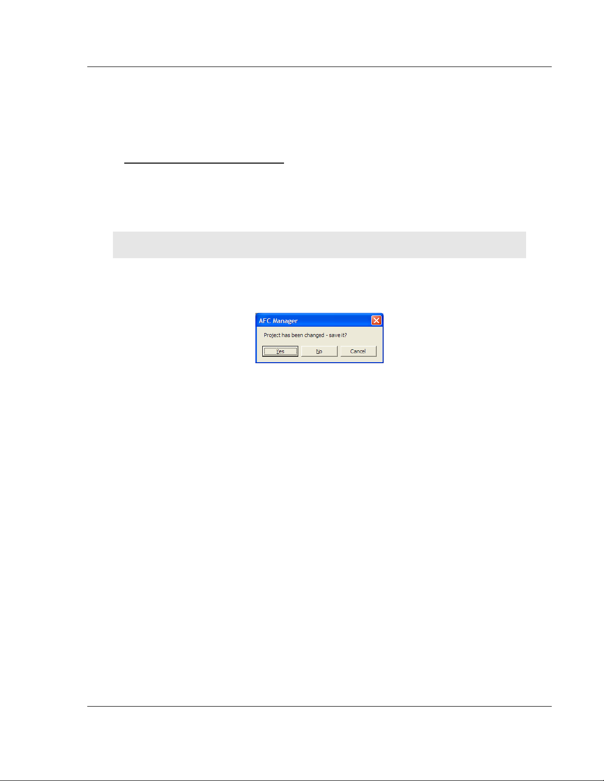
If you have made changes to the configuration that have not yet been saved, a
confirmation dialog box will open.
ESET
.
Answer Yes to save your changes, or No to discard your changes and begin
working on a new configuration. Click Cancel to abandon the attempted action
that caused this message.
ProSoft Technology, Inc. Page 23 of 316
February 25, 2011
Page 24
Quick Start MVI56-AFC ♦ ControlLogix Platform
User Manual Liquid and Gas Flow Computer
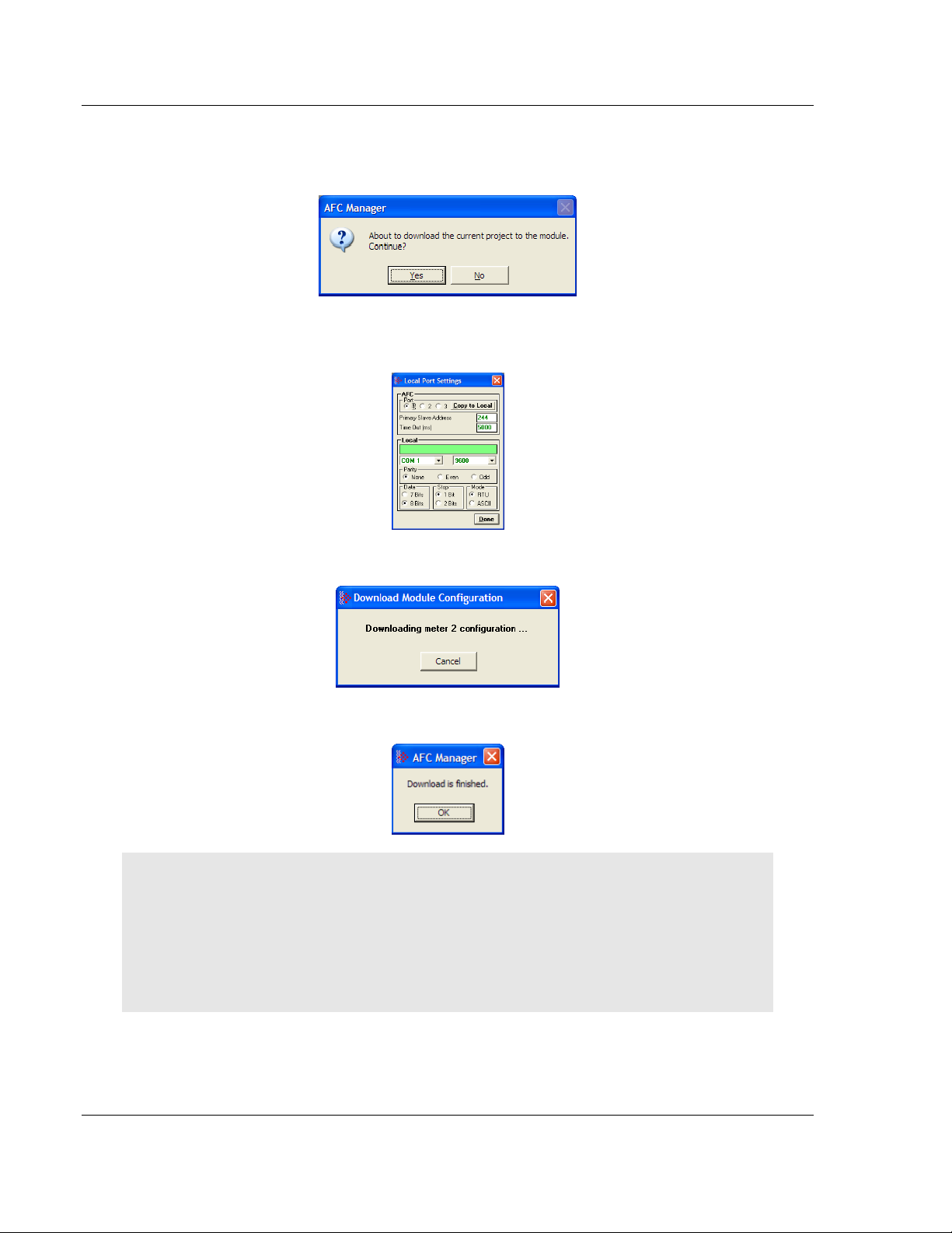
2.3.6 Downloading the Project to the Module
1 Click P
2 This action opens the Local Port Settings window. Enter the port parameters
to use, and then click D
3 During the download operation, the following progress window is displayed:
ROJECT / DOWNLOAD PROJECT
ONE
.
.
4 When the file transfer is complete, the following window is displayed:
Note: The virtual slave remapping data (page 74) is not downloaded during the procedure because
it requires a separate download operation.
Troubleshooting Tip: If the AFC Manager displays an "Illegal Data Value" message, it typically
indicates an invalid meter type or product group configuration. The module does not accept a
configuration file that attempts to change a meter type or product group for a meter that is currently
enabled. Disable all meters, change the meter types and product groups, and then enable the
meters again.
Page 24 of 316 ProSoft Technology, Inc.
February 25, 2011
Page 25

MVI56-AFC ♦ ControlLogix Platform Quick Start
Liquid and Gas Flow Computer User Manual
2.3.7 Verifying Correct Operation
When all of the configuration steps have been completed, the module should be
ready to perform measurement calculations. To verify that the module is
configured correctly, follow these steps:
1 Enable all meters that will be used, as any meter will only perform
calculations if it is enabled. Any meter can be enabled either with ladder logic
(MVI56-AFC modules), function blocks (PTQ modules) or with AFC Manager.
2 Make sure that the wallclock is running, and that it has valid date and time
information. After power-up, the wallclock will be stopped, therefore the
module will not perform any time-scheduled operations, such as writing
period-end archives, and will not timestamp records written to the event log
until it receives a wallclock command from the ladder logic.
The sample ladder logic programs the wallclock update command upon
detecting "power-up" status from the AFC. The date/time information used is
the same as the processor, therefore you should use the configuration tool for
your processor to verify that the processor has valid date/time data. If the
processor wallclock is not valid (for example if the year = 1900), the module
will not accept the command. You may easily determine if the wallclock is
running by performing two consecutive read operations in the Meter Monitor.
3 Make sure that the meter does not have any alarms. A meter alarm may
affect flow calculation. Look at the Meter Monitor dialog box for alarms.
4 Make sure that the input parameters transferred from the processor are
correct. You can look at these values in the Meter Monitor dialog box.
5 When using a pulse meter, make sure that the pulse input rollover parameter
in Meter Configuration matches the actual input rollover value used in the
high speed counter module.
ProSoft Technology, Inc. Page 25 of 316
February 25, 2011
Page 26
Quick Start MVI56-AFC ♦ ControlLogix Platform
User Manual Liquid and Gas Flow Computer
2.4 Ladder Logic Implementation
The sample ladder logic performs tasks that are covered in the Ladder Logic
sections of this manual. The most important task is to continuously write meter
process input variables from the processor to the module, and read calculation
results from the module to the processor.
Refer to the Ladder Logic sections for instructions on how to transfer the meter
process variables from the processor to the module. Ladder logic is required to
move the process variables to the correct data file or controller tag in the
processor.
The Meter Monitor window (Process Inputs field) displays the values that are
transferred from the processor.
Page 26 of 316 ProSoft Technology, Inc.
February 25, 2011
Page 27
MVI56-AFC ♦ ControlLogix Platform Quick Start
Liquid and Gas Flow Computer User Manual
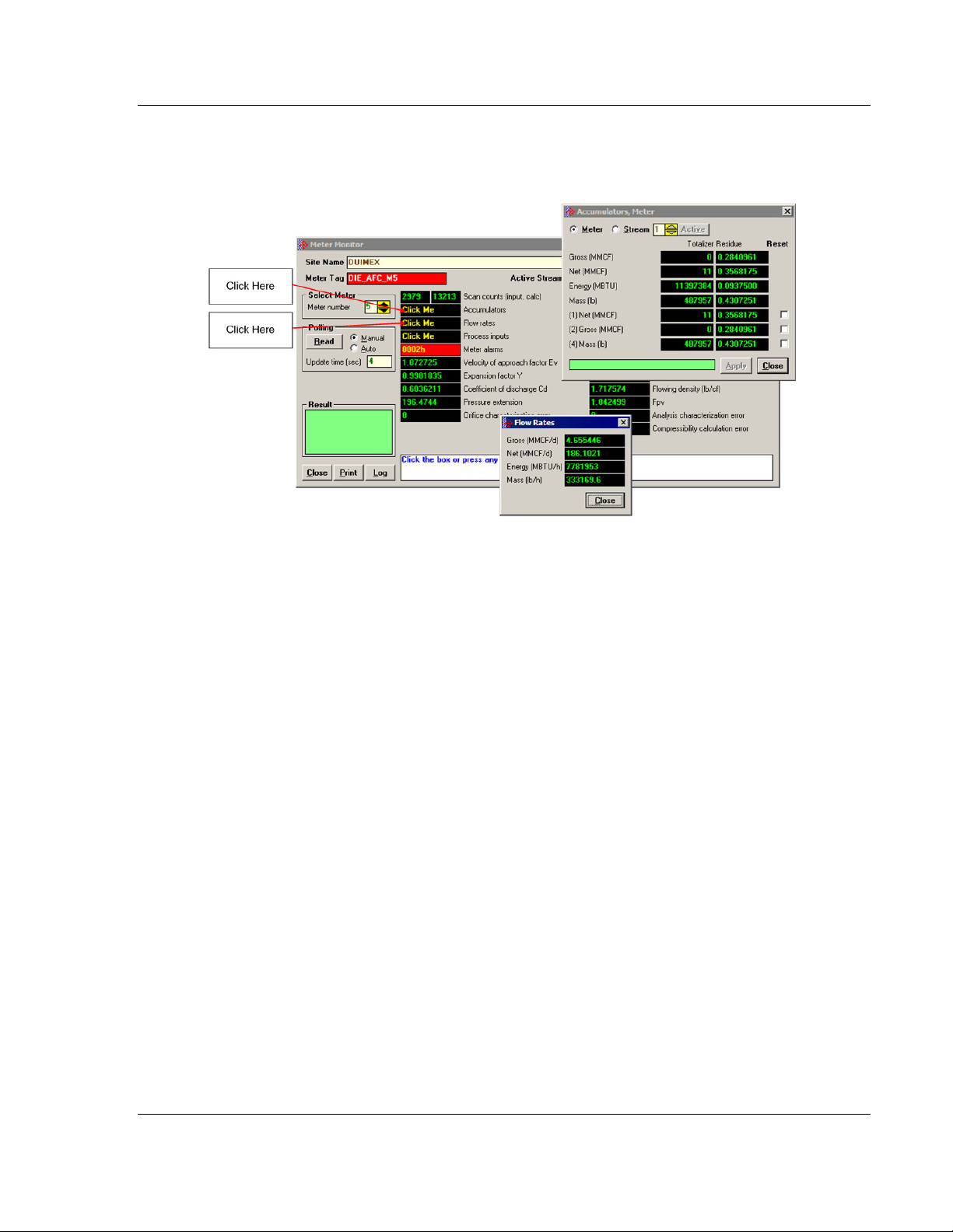
The values calculated by the module are continuously transferred to the
processor. You can refer to the Meter Monitor window to verify results
calculated by the module.
Refer to the Ladder Logic section for more information regarding the data files
and controller tags that store the calculation results transferred from the module
(for example, accumulator, flow rate, and so on).
ProSoft Technology, Inc. Page 27 of 316
February 25, 2011
Page 28

Quick Start MVI56-AFC ♦ ControlLogix Platform
User Manual Liquid and Gas Flow Computer
2.5 Setting the Wallclock
After power-up, the module must receive valid wallclock data from the ladder
logic to perform time-scheduled operations and to properly timestamp historical
records. The sample ladder logic automatically writes the wallclock upon
detecting power-up status from the AFC using the processor’s date and time
information. You should ensure that the processor contains valid date and time
information. If it does not, the module may not accept the wallclock block.
You can verify the wallclock information using the Meter Monitor section as
shown in the following example:
Refer to the Sample Ladder Logic section for more information on this topic.
Page 28 of 316 ProSoft Technology, Inc.
February 25, 2011
Page 29

MVI56-AFC ♦ ControlLogix Platform Quick Start
Liquid and Gas Flow Computer User Manual
2.6 Module Initialization
When the module is powered up for the first time, both the OK and ERR BBRAM
LEDs are illuminated. This indicates that the module is in the Cold Start state and
is not yet ready to perform calculations. The following steps initialize the module:
Enable at least one meter
Set the processor to RUN mode
After these two steps are accomplished, the state is changed from Cold Start to
Released. This indicates that that module is ready to perform flow calculations.
When in the Released state, the OK LED is ON and the ERR LED is off.
When the module is ready, you will use AFC Manager to monitor meter
operation, archives, and events. The AFC Manager User Manual contains
detailed information on these tasks.
ProSoft Technology, Inc. Page 29 of 316
February 25, 2011
Page 30

Quick Start MVI56-AFC ♦ ControlLogix Platform
User Manual Liquid and Gas Flow Computer
Page 30 of 316 ProSoft Technology, Inc.
February 25, 2011
Page 31

MVI56-AFC ♦ ControlLogix Platform Meter Channel Functionality
Liquid and Gas Flow Computer User Manual
3 Meter Channel Functionality
In This Chapter
Meter Channels ..................................................................................... 32
Linear (Pulse) Meter Overview .............................................................. 33
Differential (Orifice) Meter Overview ..................................................... 34
Gas Product Overview........................................................................... 35
Liquid Product Overview........................................................................ 36
General Features .................................................................................. 37
ProSoft Technology, Inc. Page 31 of 316
February 25, 2011
Page 32

Meter Channel Functionality MVI56-AFC ♦ ControlLogix Platform
User Manual Liquid and Gas Flow Computer
3.1 Meter Channels
Each meter channel can be assigned as a linear meter (e.g. a pulse meter) input
or as a differential meter (e.g an orifice meter) input for flow measurement using
either SI (metric) or US units. Selecting the differential meter causes the module
to use the AGA 3 standard for flow calculation (for a gas orifice meter you may
optionally choose ISO 5167-2 instead). Selecting the linear meter causes the
module to use the AGA 7 standard for gas flow calculation.
Each meter channel can be configured for gas or liquid (crude or refined)
product. The Product Group essentially selects the API/AGA Standards to be
used in calculating flow rates/increments.
Selecting "Gas" causes use of AGA8 and either AGA3 or AGA7 Standards.
Selecting any liquid group causes use of API MPMS Chapter 11(tables
23/24/53/54) and related Standards. "Crude oils, JP4" and "Oil-water emulsion
Crd)" use the, "A", tables. “NGLs, LPG’s” and “Oil-water emulsion (NGL) use the
“E” tables. "Refined Products" use the "B" tables. "Lubricating oils" use the "D"
tables, and "Special applications" use the "C" tables. "Crude oils, JP4" and
"NGLs/LPG" are used for propane, butane, NGLs (natural gas liquids), and crude
oils which are relatively water-free (less than 5 percent). The two "Oil-water
emulsion" groups are used for crude and NGL/LPG that might have a high
concentration of water for which API MPMS Chapter 20.1 is applicable. "Refined
products (xJP4)” is used for lighter refined liquids such as gasolines, jet fuels
(except JP4), and fuel oils. "Lubricating oils” is used for heavier refined liquids.
"Special applications" is used for those liquids that cannot reasonably be
assigned to one of the other groups; for this product group an explicit coefficient
of thermal expansion must be supplied.
The following table provides a brief overview of the standards used according to
the Meter Type and Product Group:
Meter Type Product Group Standards
Differential Gas AGA8, AGA3/ISO5167
Differential Liquid MPMS ch 11 AGA3/ISO5167
Linear Gas AGA8, AGA7
Linear Liquid MPMS ch 11, MPMS ch12.2
Note: The meter channel must be disabled in order to change its meter type and product group.
Page 32 of 316 ProSoft Technology, Inc.
February 25, 2011
Page 33

MVI56-AFC ♦ ControlLogix Platform Meter Channel Functionality
Liquid and Gas Flow Computer User Manual
3.2 Linear (Pulse) Meter Overview
The module typically receives the pulse count and pulse frequency values from a
high-speed counter module. The module uses these values to perform
calculations.
You can configure the primary input to be used for volume calculation. You can
configure it as Pulse Count or Pulse Frequency.
3.2.1 Primary Input = Pulse Count
If you select Pulse Count as the primary input, the module uses the pulse count
value transferred through the backplane as the primary input for volume
calculation. In this case, the pulse frequency will be used for flow rate calculation
only.
3.2.2 Primary Input = Pulse Frequency
If you select Pulse Frequency as the primary input, the module uses the pulse
frequency value transferred through the backplane as the primary input for both
flow accumulation and flow rate calculation. The pulse count value is ignored by
the module.
ProSoft Technology, Inc. Page 33 of 316
February 25, 2011
Page 34

Meter Channel Functionality MVI56-AFC ♦ ControlLogix Platform
User Manual Liquid and Gas Flow Computer
3.3 Differential (Orifice) Meter Overview
The static pressure of the gas stream can be measured either upstream of the
meter (before the differential pressure drop), or downstream of the meter (after
the pressure drop). Both AGA3 and AGA8 require the upstream static pressure
for their calculations, where:
upstream pressure = downstream pressure + differential pressure
If the pressure is measured from a downstream tap (typical), the Downstream
Static Pressure option should be set through the AFC Manager.
The module also supports the V-Cone device. You can configure V-Cone meters
and downstream selections in AFC Manager, on the Meter Configuration /
Calculation Options dialog box.
3.3.1 Primary Input = Differential Pressure
The primary input parameter configures the value used as source for the
accumulator calculation. If the parameter is set to Differential Pressure, the
module uses the differential pressure value transferred through the backplane for
accumulator calculation.
3.3.2 Primary Input = Flow Rate
You can configure the primary input parameter as flow rate in order to use this
value for the accumulator calculation.
Note: The flow rate can be converted to a different unit.
The AFC Manager software supports the following parameters:
Orifice Plate and Meter Tube Measured Diameter
Orifice Plate and Meter Tube Measurement Temperature
Orifice Plate and Meter Tube, Coefficient of Thermal Expansion
DP Flow Threshold (kPa)
DP Alarm Threshold (kPa)
Page 34 of 316 ProSoft Technology, Inc.
February 25, 2011
Page 35

MVI56-AFC ♦ ControlLogix Platform Meter Channel Functionality
Liquid and Gas Flow Computer User Manual
3.4 Gas Product Overview
The gas compressibility calculations are based on molar analysis concentrations
of up to 21 components, using the Detail Characterization Method of AGA8
(1992). The module automatically generates alarms if the sum of the molar
concentrations is not 100%
Configure the analysis settings using the AFC Manager (Meter Configuration /
Analysis Config) as follows. This window allows the selection of the
components(Component Selection Map) and analysis precision (Precision and
Stream Assignment – version 2.06.000 or higher). The sample ladder logic
assumes that all components are selected so check all components at the
Component Selection Map window.
Enter the gas analysis concentrations by clicking the Analysis button.You can
also update the concentrations through the backplane as will be later shown in
this User Manual.
The module records events every time a molar concentration value changes. For
applications that involve gas chromatograph devices, this feature might not be
desirable because it is expected that the values should frequently change. You
can disable this feature using AFC Manager (Meter Configuration / Control
Options / Treat Analysis as Process Input).
ProSoft Technology, Inc. Page 35 of 316
February 25, 2011
Page 36

Meter Channel Functionality MVI56-AFC ♦ ControlLogix Platform
User Manual Liquid and Gas Flow Computer
3.5 Liquid Product Overview
The module supports applications involving crude or refined oil such as crude oil,
oil/water emulsion, propane, butane, NGLs, LPGs, gasoline, jet fuels and
lubricating oils.
When measuring liquids with density correction, density at flowing conditions is
required. This value may be provided directly as a process input, or the module
can calculate a density from the frequency provided by a densitometer device.
3.5.1 To use a densitometer
Follow the steps below to use a densitometer.
1 Configure it, entering all configuration parameters directly from the calibration
data sheet supplied by the densitometer manufacturer.
2 Supply the frequency output from the densitometer in Hz as a floating-point
value in the "Flowing density" process-input location over the backplane
(refer to the Backplane Communication section for your platform in the
MVI56-AFC manual to determine the correct location). The AFC then
calculates a flowing density value, which is then validated by the range check
mandated by the "Density" values of "Process Input Scaling" of the meter
configuration. The "Scaling" sub-selection is not used against the frequency
input, however; the frequency is always input as floating-point.
Note: If using the Densitometer feature, select the Density Process Input Scaling for 4 to 20mA
and enter the densitometer frequency as a floating-point value.
3.5.2 Module Configuration
3.5.3 Density Units
The liquid density units can be expressed as:
Density is in kg/m3
Relative density 60ºF/60ºF
API gravity
3.5.4 Measuring Water Diluent
For liquid measurement applications, the optional automatic calculation of Net Oil
Volume and mass based on the Sediment and Water (S&W) percent input is
supported. Only provide the S&W percent value in the specified controller
register. The module puts the gross standard (or gross clean oil), net oil and
water accumulations in separate accumulators. Refer to Net Accumulator
Calculation (page 89).
Page 36 of 316 ProSoft Technology, Inc.
February 25, 2011
Page 37

MVI56-AFC ♦ ControlLogix Platform Meter Channel Functionality
Liquid and Gas Flow Computer User Manual
3.6 General Features
3.6.1 Process Variable Interface
Process variables for each of the meter runs must be produced by the controller
for consumption by the AFC module. A versatile architecture for backplane
transfer of process variables and other data and signals allow you to easily
implement the data transfer. The sample ladder logic automatically transfers the
process variables to the module and reads the calculation results to the
processor.
3.6.2 Meter Scan Time
For good measurement, the process I/O must be sampled, and the flow
calculations completed quickly in order to avoid losing process information and
measurement accuracy. The process I/O scan time for the module is under one
second for all meter runs.
Note: This is time-dependent on design of the ladder logic implemented to support the two-way
data transfer between the AFC module and the controller. The meter calculation scan independent
of the process I/O scan may take longer.
3.6.3 Multiple Meter Accumulators
Each meter channel supports the following set of full 32-bit accumulators that
may be configured in binary or split decimal format with user-defined rollover
values:
Gross Volume
Gross Standard Volume (liquid only)
Net Volume
Mass
Water (liquid only)
Energy (gas only)
Access to the above accumulators is available directly from the Modbus Slave
communications ports.
3.6.4 Product Batching
Any or all of the available meter runs may be configured for field installation that
requires shipping and/or receiving product batches of predetermined size. The
configuration utility option of selecting resettable accumulators provides a simple
way to use the power of ladder logic to design product batching, monitoring, and
control tailored to suit specific field requirements.
The Meter Signals feature can be used to create an archive or reset an
accumulator after the batch is concluded. Refer to the Ladder Logic section for
your platform for more information on using this feature.
ProSoft Technology, Inc. Page 37 of 316
February 25, 2011
Page 38

Meter Channel Functionality MVI56-AFC ♦ ControlLogix Platform
User Manual Liquid and Gas Flow Computer
3.6.5 Data Archiving
The module supports the archiving of data for each meter channel. Each time,
one record consisting of all the associated data is date and time stamped and
archived. This option allows for archiving each hour for 2 days (48 records per
meter run) and every day for 35 days (35 daily records per meter run) for each
meter channel. Each record consists of up to 40 process and other variables.
Archives are mapped to the local Modbus Table. Refer to Archives (page 91) for
more information about this topic.
3.6.6 Event Log Function
The module can log up to 1999 critical events in an Event Log File stored as a
set of easily accessible Modbus registers in non-volatile RAM. Changing critical
parameters, such as orifice plate size, Meter Base K factors, and Meter
Correction Factors, are time stamped and logged. Refer to Events for more
information about this topic.
3.6.7 Measurement Units
This option is provided for each meter channel to be configured with SI or US
units of measurement. Units for flow totalization (volumetric and mass) and flow
rate monitoring are configurable for each meter channel separately if the default
configuration is not applicable. Each meter channel may be configured to use
any of the standard units from liters/gallons to thousand cubic meters/barrels.
The flow rate period of each meter channel may be selected from flow rate per
second, per minute, per hour, or per day.
Page 38 of 316 ProSoft Technology, Inc.
February 25, 2011
Page 39

MVI56-AFC ♦ ControlLogix Platform Meter Channel Functionality
Liquid and Gas Flow Computer User Manual
3.6.8 Process Input Scaling
The module allows you to either pre-scale the process inputs via ladder logic for
use in the measurement calculations, or provide unscaled values from the analog
input modules directly. In the second case, the scaling is done internally. You can
directly enter the zero-scale, the full-scale, and the default values for each of the
process variable inputs through the configuration window. Pre-scaled values may
be transferred as floating point or as scaled integer.
When selecting scaled integer, the integer values are scaled as follows:
Scaled Integer
Variable Format Example
Temperature Two decimal places implied A value of 1342 would be
equivalent to 13.42°C
Pressure No decimal places implied for SI
units (kPa) and one decimal
place implied for U.S. units (psi).
Differential Pressure Two decimal places implied for
inches of H2O and 3 places for
kPa
Density (kg/m3) One implied decimal place A value of 5137 would be
Density (Relative Density) Four implied decimal places A value of 10023 would be
Density (API) Two implied decimal places A value of 8045 would be
A value of 200 would be
equivalent to 200kPag
A value of 35142 would be
equivalent to 35.142kPa
equivalent to 513.7 kg/m3
equivalent to 1.0023 60F/60F.
equivalent to 80.45 °API.
When selecting the 4 to 20mA process input scaling, the module uses the
following ranges:
4 to 20mA
Processor Module 0% 100%
SLC MVI46-AFC 3277 16384
ControlLogix MVI56-AFC 13107 65535
CompactLogix MVI69-AFC 6241 31206
PLC MVI71-AFC 819 4095
Quantum PTQ-AFC 4000 20000
The module uses the configured values for zero and full scale to interpret the
process input scaling.
In the Meter Monitor window, the raw values as transferred from the processor
are shown at the "Last Raw" column and the converted values are shown at the
"Scaled Avg" column.
ProSoft Technology, Inc. Page 39 of 316
February 25, 2011
Page 40

Meter Channel Functionality MVI56-AFC ♦ ControlLogix Platform
User Manual Liquid and Gas Flow Computer
Page 40 of 316 ProSoft Technology, Inc.
February 25, 2011
Page 41

MVI56-AFC ♦ ControlLogix Platform Meter Proving
Liquid and Gas Flow Computer User Manual
4 Meter Proving
In This Chapter
Prover Configuration ............................................................................. 42
Setting up the AFC module for Meter Proving ....................................... 51
Meter Proving Reports........................................................................... 63
Protected Meter Proving Data in the AFC's Input Register Bank .......... 64
As meters continue to be used over time, the meter’s measurement accuracy
deteriorates. Many things can cause the flow sensor bearings to wear down
beyond specified limits so that meters are measuring lower volume levels
causing producers to pump more oil than the consumer is buying. Meter Provers
have a “Known Traceable Volume” which allows using actual flowing and
operating conditions to establish a meter correction factor to restore
measurement accuracy.
There are 4 types of provers. This chapter will give a basic overview for each
type, its options, and configuration.
The Unidirectional Pipe Prover
The Bidirectional Pipe Prover
The Compact Prover
The Master Meter
ProSoft Technology, Inc. Page 41 of 316
February 25, 2011
Page 42

Meter Proving MVI56-AFC ♦ ControlLogix Platform
User Manual Liquid and Gas Flow Computer
4.1 Prover Configuration
Prover type is a parameter that identifies the basic type of the prover. It's values
are:
N
O PROVER CONFIGURED
U
NIDIRECTIONAL PIPE PROVER
(You may also choose this selection for an
atmospheric tank prover.)
B
IDIRECTIONAL PIPE PROVER
C
OMPACT (SHORT, SMALL VOLUME) PROVER
M
ASTER METER
4.1.1 Prover Type
Prover characteristics and configurations will vary based on the type of prover
and options you select. The following topics describe each type of prover.
Page 42 of 316 ProSoft Technology, Inc.
February 25, 2011
Page 43

MVI56-AFC ♦ ControlLogix Platform Meter Proving
Liquid and Gas Flow Computer User Manual
Unidirectional Pipe Prover
This is a long pipe, with a ball or piston that fills the pipe and moves with the
fluid flow. At each end of the pipe is a switch that is tripped when the ball
passes it. A proving run counts the pulses occurring between the switch trips.
A run is prepared by positioning the ball in a cul-de-sac upstream of the first
switch, ready to be injected into the stream. At the end of the run, the ball is
extracted from the stream and returned via another path to the upstream end.
In order to calculate a meter factor with sufficient precision, the prover volume
must be large enough to count sufficient pulses. Therefore, unidirectional
provers can be quite large.
ProSoft Technology, Inc. Page 43 of 316
February 25, 2011
Page 44

Meter Proving MVI56-AFC ♦ ControlLogix Platform
User Manual Liquid and Gas Flow Computer
Bidirectional Pipe Prover
This is similar to a unidirectional prover, except that use is made of the deadhead
transfer of the ball back to its starting point. Instead of returning the ball via a
separate path, valves are swung to reverse the direction of flow in the prover and
the ball is returned along its original path to trip the switches a second time in the
opposite order. The first pass of the ball is called the forward leg and the second
is called the backward or return leg. The pulse count for the run is then the sum
of the counts for the two legs. Because the run's pulse count arises from two
passes between the switches, a bidirectional prover need be only half the volume
of its unidirectional counterpart and can be correspondingly smaller.
Page 44 of 316 ProSoft Technology, Inc.
February 25, 2011
Page 45

MVI56-AFC ♦ ControlLogix Platform Meter Proving
Liquid and Gas Flow Computer User Manual
Compact (short, small volume) Prover
Attention: While the MVI56-AFC module provides the capability to do small volume proving, an I/O
platform for ControlLogix that provides Double Chronometry pulse input signals does not exist at this
time. These pulse signals are needed for accuracy that is recommended per API standards. Use of this
module with small volume provers is not recommended as it may provide inaccurate results.
A compact prover, or small volume prover (SVP), has a short barrel or tube with a
piston that travels the length of the tube. The piston has a valve that is opened
allow it to return to its starting point without stopping the flow in the tube. Most SVPs
do not mount the switches to be tripped inside the tube. They mount the switches
externally on a bar that moves with the piston outside the tube and the switches trip
when they move past a fixed point. Each forth and back passage is called a pass.
SVPs can be much less expensive than LVPs, so they are often preferred. Due to
their small size they can collect at most a few hundred pulses during a pass. The
number of pulses in a single pass is a number too small for calculating a meter factor
with sufficient precision. The technique of double chronometry is then used to
determine a fractional pulse count of sufficient precision. Even though a single pass
in a SVP with double chronometry can yield a pulse count similar in precision to that
from a single run of a LVP, it is often the practice to accumulate several passes into a
single run so that the pulses totalized for all passes of the run yield a number large
enough for calculating the required meter factor with sufficiently high precision.
to
ProSoft Technology, Inc. Pag
February 25, 2011
e 45 of 316
Page 46

Meter Proving MVI56-AFC ♦ ControlLogix Platform
User Manual Liquid and Gas Flow Computer
Master Meter
This proving technique proves a meter by comparing its behavior to that of
another master meter whose behavior is deemed to be accurate. A master meter
itself must be proved to a high precision by using a conventional prover.
4.1.2 Prover Options
There are several options affecting the handling and representation of data, as
well as affecting the relevance and availability of some configuration items. Not
all options are available for all prover types. If an option does not apply to a
particular prover type, it cannot be selected. For a description of each option
listed below see the corresponding Modbus dictionary address in parenthesis
below.
Dual transmitters, temperature (65011.0)
Dual transmitters, pressure (65011.1)
Input meter density (65011.2)
Return leg pulse count is round –trip count (65011.4)
Prover is double-walled (65011.5)
External switch bar (65011.6)
Calculation method: Average Meter Factor (else Average Data) (65011.8)
Page 46 of 316 ProSoft Technology, Inc.
February 25, 2011
Page 47

MVI56-AFC ♦ ControlLogix Platform Meter Proving
Liquid and Gas Flow Computer User Manual
4.1.3 Run Counts
Runs per prove (65012)
The total number of completed runs that constitute a single prove. This value
must be at least 2 and must not exceed 8. If Maximum attempted runs before
abort (register 65014) is non-zero, this value must not exceed that value.
Runs per prove, selected
The total number of completed runs to be selected for contribution to the prove
calculations. This value must be at least 2 and not exceed Runs per prove,
(register 65012). This value is automatically updated when you edit the Runs per
prove field.
Maximum attempted runs before abort (65014)
The total number of runs to be attempted before abandoning a prove as
incomplete, which permits an automatic proving sequence to automatically
terminate itself under exceptionally variable conditions. If this value is zero, no
limit is imposed. Otherwise, the value must be at least as large as Runs per
prove, (register 65012) and must not exceed 65535.
4.1.4 Run Input Setup
Minimum pulses per run (thousands) (65016)
The minimum number of pulses required for a run to be considered for
contribution to the prove, represented in thousands. This value must lie between
10 (representing 10,000 pulses) and 1000 (representing 1,000,000 pulses). Runs
counting 10,000 pulses or more have sufficient precision to enable calculation of
4-digit meter factors. For all prover types except compact SVPs, the AFC rejects
any LVP run that does not meet this condition. Since SVPs can deliver fractional
pulse counts that provide sufficient precision with only a small number of pulses,
the AFC does not impose this limitation on prover calculation using SVPs.
Maximum seconds per run (65017)
This parameter is a timeout for the duration of a run. A timer is started when the
run is started, and if the timer value equals or exceeds this value before the run
is completed, then the AFC automatically cancels the run. This allows an
automatic prove to recover from conditions that put the AFC and the proving
hardware out of step, such as a missed switch signal. This value must lie
between 0 and 10000, where zero means that no timeout is imposed.
ProSoft Technology, Inc. Page 47 of 316
February 25, 2011
Page 48

Meter Proving MVI56-AFC ♦ ControlLogix Platform
User Manual Liquid and Gas Flow Computer
Input format: line meter pulse count (65020)
This parameter is a code that specifies the format in which pulse counts for the
line meter are delivered to the AFC at the ends of runs or passes. These values
are:
Value Format Description
0 None No pulse counts are delivered. Used only when no prover is configured
1 32-bit Pulse counts are delivered as 32-bit (double) integers
2 Split-double Pulse counts are delivered as split-double values, in which the actual
value is (MSW * 10,000 + LSW)
3 Floating point Pulse counts are delivered as IEEE 32-bit floating point values
When a prover is configured, the default setting is 1 (32-bit), except for compact
provers, for which it is 3 (floating point).
Input format: master meter pulse count (65021)
This parameter is a code that specifies the format in which pulse counts for the
master meter are delivered to the AFC at the ends of runs or passes. These
values are:
Value Format Description
0 None No pulse counts are delivered. Used when the prover is not a
master meter.
1 32-bit Pulse counts are delivered as 32-bit (double) integers.
2 Split-double Pulse counts are delivered as split-double values, in which the
actual value is (MSW * 10,000 + LSW).
3 Floating point Pulse counts are delivered as IEEE 32-bit floating point values.
When a master meter is configured, the default setting is 1 (32-bit). This
parameter is meaningful only when using master meter provers.
Page 48 of 316 ProSoft Technology, Inc.
February 25, 2011
Page 49

MVI56-AFC ♦ ControlLogix Platform Meter Proving
Liquid and Gas Flow Computer User Manual
4.1.5 Prover Characteristics
Prover Characteristics will vary based on the type of prover and options you
select. The following topics describe each field and its operating range.
Prover size units (65018.L)
This parameter sets the units in which the prover's base volume is represented.
This parameter is not meaningful for master meter provers.
Meter factor precision (65028+)
This parameter is a number between 0.00000001 and 0.0001. The default setting
is 0.0001
Pulse interpolation ratio (65030+)
Meter-proving pulse counts delivered to the AFC may be fractional, such as
when double chronometry is used with a SVP. This value is the number of
delivered counts that constitute a single actual pulse, so that the actual pulse
count is determined by dividing the delivered count by this. The default value is
1000.0 for compact provers and 1.0 for other types. This parameter is meaningful
only for non-master meter provers.
Flow tube linear coefficient of thermal expansion (65032+)
Holds the coefficient of thermal expansion of the prover barrel material,
meaningful only for non-master-meter provers. Here are some typical materials
and their expansion coefficients.
Stainless steel 304 or 316 9.3e-6/°F 16.7e-6/°C
Monel 7.9e-6/°F 14.3e-6/°C
Carbon steel 6.2e-6/°F 11.2e-6/°C
Invar .8e-6/°F 1.4e-6/°C
The default value is that of carbon steel, 6.2e-6/°F 11.2e-6/°C.
Switch bar linear coefficient of thermal expansion (65034+)
Holds the coefficient of thermal expansion of the external switch bar material,
meaningful only for non-master-meter provers with option External switch bar
(register 65011 bit 6) set. Here are some typical materials and their expansion
coefficients.
Stainless steel 304 or 316 9.3e-6/°F 16.7e-6/°C
Monel 7.9e-6/°F 14.3e-6/°C
Carbon steel 6.2e-6/°F 11.2e-6/°C
Invar .8e-6/°F 1.4e-6/°C
The default value is that of invar .8e-6/°F 1.4e-6/°C.
ProSoft Technology, Inc. Page 49 of 316
February 25, 2011
Page 50

Meter Proving MVI56-AFC ♦ ControlLogix Platform
User Manual Liquid and Gas Flow Computer
Base prover volume (65036+)
Holds the base volume of the prover barrel as determined by the water-draw
method, in the units specified by Prover size units (register 65018.L). This
parameter is meaningful only for non-master meter provers.
The accepted standards mandate that the base volume of a bidirectional prover
be that registered by a round trip of the displacer.
Flow tube inside diameter (mm) (65038+)
This parameter is the measured inside diameter of the prover barrel at standard
(base) conditions and is meaningful only for non-master meter provers with the
option Prover is double-walled (register 65011 bit 5) clear.
Flow tube wall thickness (mm) (65040+)
This parameter is the measured thickness of the prover barrel wall, and is
meaningful only for non-master meter provers with the option Prover is double-
walled (register 65011 bit 5) clear.
Flow tube modulus of elasticity (65042+)
This parameter is the prover barrel material modulus of elasticity, and is
meaningful only for non-master meter provers with the option Prover is double-
walled (register 65011 bit 5) clear. The default value is that of carbon steel,
206.8e+6 kPa or 30.00e+6 psi.
Page 50 of 316 ProSoft Technology, Inc.
February 25, 2011
Page 51

MVI56-AFC ♦ ControlLogix Platform Meter Proving
Liquid and Gas Flow Computer User Manual
4.2 Setting up the AFC module for Meter Proving
First, configure the parameters in the Prover Configuration dialog box. A
Bidirectional Pipe Prover is shown in this example.
Note: Changing prover type will reset all prover configuration
Meter Proving dialog box
This window is used to connect to the module to manage the prove and/or
monitor prove status and results from the Modbus database.
ProSoft Technology, Inc. Page 51 of 316
February 25, 2011
Page 52

Meter Proving MVI56-AFC ♦ ControlLogix Platform
User Manual Liquid and Gas Flow Computer
This is a typical configuration for a meter proving setup. Your application may
vary from the example shown.
Page 52 of 316 ProSoft Technology, Inc.
February 25, 2011
Page 53

MVI56-AFC ♦ ControlLogix Platform Meter Proving
Liquid and Gas Flow Computer User Manual
4.2.1 Initial Requirements
In its current version, the AFC supports proving of only liquid products, measured
with linear devices that use pulse counts as the primary input variable, where
each pulse represents a specific liquid volume.
In the Meter Configuration dialog box above, Meter 1 is used in this example as
the meter selected to be proved. It can be proved using any one of the four
provers that the AFC supports. These provers are described in the Prover
Configuration section. There is an Identification button which opens an editable
options window, shown below. Text entered here appears on the proving report.
ProSoft Technology, Inc. Page 53 of 316
February 25, 2011
Page 54

Meter Proving MVI56-AFC ♦ ControlLogix Platform
User Manual Liquid and Gas Flow Computer
4.2.2 Meter Proving Alarms
These alarms are transient and any one might exist only for a single scan, so
they might be missed when viewing this register directly. However, alarms are
also accumulated into the results database, so alarms that have occurred during
any run may be viewed by inspecting that database.
To Check for Alarms
1 Activate Meter Monitor dialog box
2 Select M
3 Click on the [R
Note: Verify that the meter is not generating any alarms. Meter proving cannot proceed while any
alarm is displayed.
ETER
to be proved
EAD
] button
This is accomplished by providing P
ROCESS PARAMETER
values that are within
the range of the Process Input Scaling Dialog box.
There are two sources of alarms:
1 From the meter, which occur whether or not a prove is in progress. These are
illustrated above.
2 From the prove, and there are 2 kinds:
a) Variation Limit Alarms
b) Prove Calculation Alarms
Note: Any alarm will always make a run not able to be selected.
Page 54 of 316 ProSoft Technology, Inc.
February 25, 2011
Page 55

MVI56-AFC ♦ ControlLogix Platform Meter Proving
Liquid and Gas Flow Computer User Manual
Variation Limit Alarms
These alarms are due to variation outside the configured limits:
Bit/Byte Description Modbus Dictionary Address
01 Prover inlet temperature 65050
02 Prover outlet temperature 65052
03 Prover inlet-outlet temperature 65054
04 Prover temperature 65056
05 Prover-meter temperature 65058
06 Switch bar temperature 65060
07 Meter pressure 65062
08 Prover inlet pressure 65064
09 Prover outlet pressure 65066
10 Prover inlet-outlet pressure 65068
11 Prover pressure 65070
12 Prover-meter pressure 65072
13 Meter density 65074
14 Prover density 65076
15 Prover-meter density 65078
16 Water content 65080
17 Meter flow rate 65082
18 Prover flow rate 65084
19 Pulses over runs 65086
20 Pulses over passes 65088
21 Not enough pulses in run N/A
22-31 [Reserved] N/A
ProSoft Technology, Inc. Page 55 of 316
February 25, 2011
Page 56

Meter Proving MVI56-AFC ♦ ControlLogix Platform
User Manual Liquid and Gas Flow Computer
Prove Calculation Alarms
These alarms arise from prove calculations (e.g. outside API limits):
Bit/Byte Description
00 [Reserved]
01 CTS prover
02 CPS prover
03 [Reserved]
04 High water
05 CTW
06 CPW
07 Density correction
08 CTL prover
09 CPL prover
10 CSW prover
11 Vapor pressure prover
12 CTL meter
13 CPL meter
14 CSW meter
15 Vapor pressure meter
16 Repeatability
17 Change in factor
18-22 [Reserved]
23 Divide by zero
24-31 [Reserved]
Page 56 of 316 ProSoft Technology, Inc.
February 25, 2011
Page 57

MVI56-AFC ♦ ControlLogix Platform Meter Proving
Liquid and Gas Flow Computer User Manual
4.2.3 Prover Operation (How to do a Prove)
You must first configure a prover, and configure the channel of a Configurable
Flow Meter (CFM) or High Speed Counter (HSC) module for proving.
Note: CFM modules are available for the 1756 platform from Rockwell Automation, and the
Quantum platform via Spectrum. Any HSC card will work for the other modules, but if you use an
HSC, you will need extra ladder logic in the PLC to implement proving.
Once the parameters for the proving session have been configured, (pipe
diameter, water-draw volume, wall thickness, tolerances and limits on the
variation of temperature, flow rate, and other process variables), and the prove
setup has been completed, the entire proving session can be completely
automated within the PLC ladder logic.
Steps for proving a meter
a Enter the prover parameters and variation limits (configuration)
b Enter the number of the meter to be proved (setup)
c Set the enable prove signal bit. This function verifies that the selected
meter is provable (a liquid pulse meter), and clears the proving results for
a new proving session.
d Enable the counter card channel for proving, and launch the ball. When
the first switch is tripped, set the run start signal bit. During the run,
continuously copy the prover temperature, pressure, density, etc, to the
AFC, so that it may monitor their variation and accumulate them for final
averaging. For the same purpose, the AFC module itself retrieves meter
process variables directly from the meter input from the PLC without PLC
intervention.
e When the second switch is tripped, copy the final pulse count from the
counter card channel to the proper location and set the run stop signal bit
This function computes results for the completed run (averages of
process variables, variation limit alarms, etc.), and also computes results
for the entire prove over all completed runs (averages of run averages,
variation limit alarms, API calculations and calculation alarms, final meter
factor and change in meter factor, and number of completed runs). Upon
a run start or accept prove signal, any bad runs are deleted from the
prove before continuing with the remainder of the signaled function.
f When a sufficient number of runs have been completed , set either the
accept prove or the reject prove signal, which function marks the data in
the prover results accordingly.
ProSoft Technology, Inc. Page 57 of 316
February 25, 2011
Page 58

Meter Proving MVI56-AFC ♦ ControlLogix Platform
User Manual Liquid and Gas Flow Computer
Missed Switch
It is possible that the tripping of the second switch to end a run is not seen by
the PLC (due to a broken wire or poorly lubricated switch), leaving the AFC and
the physical prover in inconsistent states. You may recover from this condition
with the Run Cancel signal, which clears any active run and resets the AFC to be
ready to start a new run. Data from any bad run will also be deleted by the Run
Cancel.
Proving Controls
These bits supply parameter information to the Enable prove and Accept prove
signals (register 65308 bits 1 and 2 respectively). Control bits 0 through 7
parameterize the Enable and bits 8 through 15 parameterize the Accept. Controls
are latched into the results database upon receipt of a signal. Changes thereafter
have no effect on the state of these control bits.
Proving Signals
A prover signal instructs the AFC to immediately perform a particular function
once. A signal bit is latched by the process issuing the signal (for example, the
PLC) and is unlatched by the AFC when the function has been performed. Prover
signals are discharged upon the next proving scan, before which several Modbus
transactions may be completed. Modbus transactions to read the status of these
signal bits may, therefore, show uncleared bits for functions that have already
been scheduled but not discharged yet.
Prover Sequencing
This parameter reports the state of the proving hardware, making it available to
the prove-management software for display of prove status and possible control
of the prove. The prove-management feature of AFC Manager uses it only for
display. This value usually comes from the proving hardware integrated into the
PLC platform, therefore it is normally supplied by the PLC.
Page 58 of 316 ProSoft Technology, Inc.
February 25, 2011
Page 59

MVI56-AFC ♦ ControlLogix Platform Meter Proving
Liquid and Gas Flow Computer User Manual
Prover Phase
These bits report the state of the run as known by the proving hardware. These
values are chosen specifically for compatibility with several kinds of proving
hardware, so that the work necessary for the PLC to translate hardware register
values into these values required by the AFC is minimized and in many cases
can be reduced to a simple mask-and-copy. There are 8 values ranging from 0-
7. These values are:
Value Name Description
0 Prover not selected (not ready) This is the normal value when no proving run is in
progress.
1 Prover active, not yet counting The counter card has been initialized for a proving
run, but the ball or piston has not yet passed the
first switch. Counting of the pulses for the run has
not yet begun.
2 Prover active, past first switch and
counting
3 Prover active, past second switch This state is for bidirectional provers only. The ball
4 Prover active, past first switch return
leg
5 Run Complete The ball or piston has passed the second switch
6 Prover not selected (not ready) Some kinds of proving hardware report this value
7 Prover not selected (not ready) Some kinds of proving hardware report this value
The ball or piston has passed the first switch but not
yet passed the second switch, and the run counter
is counting pulses. For bidirectional provers, this is
the forward leg.
or piston has passed the second switch of the
forward leg, the run counter has been stopped, and
the intermediate count for the forward leg is
available. During this state
the proving hardware should be swinging valves to
reverse the stream's direction of flow through the
prover, preparing it for the return leg.
This state is for bidirectional provers only. The ball
or piston has passed the first switch on the return
leg but not yet passed the second switch, and the
run counter is counting pulses.
(for bidirectional provers, the second switch of the
return leg), the run counter has been stopped, and
the count for the run is available. For a bidirectional
prover, this count may be either the count for only
the return leg or the count for the entire run; use
prover option "Return leg pulse count is round-trip
count" (register 65011 bit 4) to specify which.
for a counting mode unrelated to proving. The AFC
treats this value the same as value 0.
for a counting mode unrelated to proving. The AFC
treats this value the same as value 0.
Prover Position: Ready for Launch
The prover's ball or piston is ready for launching into the stream. For a
bidirectional prover, this is the launch of the forward leg.
ProSoft Technology, Inc. Page 59 of 316
February 25, 2011
Page 60

Meter Proving MVI56-AFC ♦ ControlLogix Platform
User Manual Liquid and Gas Flow Computer
Prover Position: Ready for Return
For bidirectional provers only, the prover's ball or piston is ready for launching
into the stream for the return leg.
Prover Position: Valve Sealed Behind Ball
The prover's ball or piston has been launched into the stream and the sealing
valve has been closed behind it. For a bidirectional prover, this is the start of the
forward leg.
Prover Position: Valve Sealed Behind Ball, Return Leg
For bidirectional provers only, the prover's ball or piston has been launched into
the stream for the return leg and the sealing valve has been closed behind it.
Prover Temperature
Absolute
This value is the process input temperature of the prover (traditional or master
meter) in units relative to absolute zero, and is required for some calculations.
This value is meaningful only while a prove is active.
Conventional
This value is the process input temperature of the prover (traditional or master
meter) in conventional units. For a traditional prover with dual transmitters, this is
the average of the two inputs. This value is meaningful only while a prove is
active.
Prover Pressure
Absolute
This value is the process input pressure of the prover (traditional or master
meter) in absolute units. This value is calculated as (gauge pressure ) +
(barometric pressure). This value is meaningful only while a prove is active.
Gauge
This value is the process input pressure of the prover (traditional or master
meter) in gauge units. For a traditional prover with dual transmitters, this is the
average of the two inputs. This value is meaningful only while a prove is active.
Page 60 of 316 ProSoft Technology, Inc.
February 25, 2011
Page 61

MVI56-AFC ♦ ControlLogix Platform Meter Proving
Liquid and Gas Flow Computer User Manual
Prove-enable Error Code
This code reports the result of the most recent attempt to enable a prove. If the
code is zero, the prove was successfully enabled; a non-zero code reports the
reason for failure. The values are:
Value Name Description
0 The new prove has been
enabled
21
22 Line meter not liquid pulse At the present time, the meter to be proved may only
23 Incompatible measurement
24 Unimplemented product group Because of the nature of the proving calculations at
25 Unimplemented measured
28 Line meter in calibration The meter to be proved has at least one process
29 Line meter not enabled The meter to be proved is not enabled.
32 Master meter not liquid pulse At the present time, a master meter prover must be a
Requested meter number The Requested meter number (register 65300) is out
standard
quantity
The new prove has been enabled
of range, or, for a master meter prover, is the same
as that of the master meter (an attempt to self-prove
the master meter)
be a liquid pulse meter.
At the present time, the configuration of both the
prover and the line meter to be proved must specify
the same system of measurement units (US, SI) and
the same liquid density units selection (kg/m3, Rd/60,
°API).
the present time, not all product groups are provable.
Meters configured for these product groups are
provable:
Liquid (crude oils and JP4)
Liquid (refined products: gasolines, jet fuels, fuel
oils, except JP4)
Liquid (NGLs and LPGs)
Liquid (lubricating oils)
Liquid (special applications)
Meters configured for these product groups are not
provable:
Gas
Liquid (oil-water emulsion of crudes)
Liquid (oil-water emulsion of NGLs)
At the present time, only pulse meters whose pulse
train represents gross volume can be proved.
input in calibration mode. Ensure that all process
inputs are live before attempting to prove the meter.
liquid pulse meter.
ProSoft Technology, Inc. Page 61 of 316
February 25, 2011
Page 62

Meter Proving MVI56-AFC ♦ ControlLogix Platform
User Manual Liquid and Gas Flow Computer
33 Master meter incompatible
configuration
38 Master meter in calibration The master meter has at least one process input in
39 Master meter not enabled The master meter is not enabled.
51 Invalid prover parameter For a traditional (non-master-meter) prover, the base
52 Invalid prover controls
For a master meter prover, both the line meter and
the master meter must be compatibly configured,
including identical settings of:
System of measurement units (US, SI)
Liquid density units (kg/m3, Rd/60, °API)
Product group
Measured quantity (gross volume pulses)
Reference conditions (base temperature and
pressure)
API calculation options (selection of density,
temperature, and pressure corrections)
For product group 8, Special applications, the
coefficient of thermal expansion Alpha
calibration mode. Ensure that all process inputs are
live before attempting to use the master meter for
proving.
prover volume (register 65036) must be greater than
zero, and, if the prover is single-walled, the inside
diameter, wall thickness, and modulus of elasticity
(registers 65038, 65040, and 65042) must all be
greater than zero.
Some undefined bits in the at-enable controls
(register 65306 bits 0 through 7) have been set.
Page 62 of 316 ProSoft Technology, Inc.
February 25, 2011
Page 63

MVI56-AFC ♦ ControlLogix Platform Meter Proving
Liquid and Gas Flow Computer User Manual
4.3 Meter Proving Reports
Clicking on the R
Manufacturer
Model Number
Serial Number
Material Type
Prover Tag
Results of the prove will appear in this report, along with the static data
entered in the text window during setup. For more information, see Initial
Requirements (page 53).
EPORT
button generates a report with such information as:
The Meter Proving window above shows the system during a prove using a
Master Meter. Notice the differences in the example of the information that is
available before and after connecting to the module.
ProSoft Technology, Inc. Page 63 of 316
February 25, 2011
Page 64

Meter Proving MVI56-AFC ♦ ControlLogix Platform
User Manual Liquid and Gas Flow Computer
4.4 Protected Meter Proving Data in the AFC's Input Register Bank
The data concerned with Meter Proving is maintained in the Input Register Bank,
(Modbus 3xxxxx read-only Input Register Addresses), protected from change
from outside. There are two areas:
a Latest Prove Results (3x63400 to 3x63709)
b Meter Previous Prove Summary (3x61600 to 3x62399, 50 registers per
meter)
These two areas are described in better detail in the following two topics.
4.4.1 Latest Prove Results
This area contains complete details of the latest prove that has been enabled,
including
Prove setup
Prover and proved-meter configuration summary
Prove state
Prove-level calculations
Run-level input and calculations for each run of the prove
This area supplies almost all the information presented on the proving report (the
remaining info comes from the proved meter’s Previous Prove Summary; see
next). The contents of this area persist until a new prove is enabled, so a proving
report may be regenerated at any time after the prove has been completed and
before the next one is started. There is only one such area for all meters on the
AFC module; therefore enabling a new prove for any meter resets the Prove
Results from the last completed prove, regardless of which meters were involved.
Page 64 of 316 ProSoft Technology, Inc.
February 25, 2011
Page 65

MVI56-AFC ♦ ControlLogix Platform Meter Proving
Liquid and Gas Flow Computer User Manual
The Latest Prove Results is a block of 1310 registers, starting at input register
62400 and proceeding through register 63709. The table below explains these
sub-areas.
Name Module Memory
Address
Prove Status 62400 to 62409 Occupies 10 registers
Prove Setup 62410 to 62553 Occupies 140 registers and protects meter
Prove Acceptance 62554 to 62575 Occupies 22 registers and records
Prover Configuration 62576 to 62655 Occupies 80 registers and has the same
Prove Only Calculations 62656 to 62665 Occupies 10 registers and contains a few
Reading and Calculations for
Prove
Reading and Calculations for
Runs
62666 to 62781 Occupies 116 registers and the "readings"
62782 to 63709 Occupies 166 registers for each of up to 8
Description
configuration and prove setup information
for use by proving calculations and report
generation; this information remains
unchanged from the moment of enable,
regardless of how the original source
information might be altered during or after
the prove
timestamps associated with the prove,
accumulator totalizer values, and details of
the disposition of the new meter factor upon
acceptance of the prove.
purpose as Prove Setup, to protect the
prover configuration against subsequent
changes so that proving can proceed under
reliably constant parameters, and so that the
proving report can be generated and
regenerated according to the original
conditions of the prove.
calculated values that are applicable only for
the prove as a whole.
part contains the averages of the
corresponding readings for all runs of the
prove. The "calculations" part contains
calculations performed upon the prove-level
readings if calculation method "average
data" was chosen.
runs of the prove. The layout of each block
of 116 registers is identical to that of the
Readings and Calculations for Prove block.
The "readings" part contains the weighted
averages or snapshots of all process input
and counter card input for the duration of the
run. The "calculations" part contains
calculations performed upon the run-level
readings if calculation method "average
meter factor" was chosen.
ProSoft Technology, Inc. Page 65 of 316
February 25, 2011
Page 66

Meter Proving MVI56-AFC ♦ ControlLogix Platform
User Manual Liquid and Gas Flow Computer
The Latest Prove Results area has a fixed layout so that any point can always be
found at the same location regardless of setup, and with a collection of points
intended to be sufficient for a variety of setups. Consequently, many points will
be irrelevant for a given combination of prover configuration, meter configuration,
and prove setup. Those irrelevant points will have zero values in the Results area
and can be ignored. AFC Manager’s Meter Proving window does not show
irrelevant points.
Page 66 of 316 ProSoft Technology, Inc.
February 25, 2011
Page 67

MVI56-AFC ♦ ControlLogix Platform Meter Proving
Liquid and Gas Flow Computer User Manual
4.4.2 Meter Previous Prove Summary
This area contains summary data for the previous prove of each of the AFC’s
meter runs. Each time a new prove is enabled and before the Prove Results
area is reset, summary prove information for the meter previously proved (if any)
is copied to the meter’s Previous Prove Summary block, overwriting the old
information. This area supplies a small amount of the information presented in
the proving report.
The Previous Prove Summary block for each meter occupies 50 registers. Meter
#1’s block begins at input register 61600, so that Meter #2’s block is at 61650,
and so on; registers 61600 to 62399 are allocated to the Previous Prove
Summary blocks for up to 16 meter runs.
ProSoft Technology, Inc. Page 67 of 316
February 25, 2011
Page 68

Meter Proving MVI56-AFC ♦ ControlLogix Platform
User Manual Liquid and Gas Flow Computer
Page 68 of 316 ProSoft Technology, Inc.
February 25, 2011
Page 69

MVI56-AFC ♦ ControlLogix Platform Modbus Database
Liquid and Gas Flow Computer User Manual
5 Modbus Database
In This Chapter
AFC Modbus Address Space ................................................................ 70
Primary Slave ........................................................................................ 71
Virtual Slave .......................................................................................... 74
The module supports two individual Modbus slaves (Primary and Virtual) to
optimize the polling of data from the remote SCADA system, or from the
processor (through the backplane). Refer to the Modbus Dictionary dialog box in
AFC Manager for information about Modbus addressing.
ProSoft Technology, Inc. Page 69 of 316
February 25, 2011
Page 70

Modbus Database MVI56-AFC ♦ ControlLogix Platform
User Manual Liquid and Gas Flow Computer
5.1 AFC Modbus Address Space
Addressable Modbus registers are divided into four banks as shown in the
following table.
MODBUS Address Space Allocation: Total Modbus Registers: 131,072
Primary Slave Banks
(131072 registers)
Holding Registers Input Registers Holding Registers Input Registers
From: 0 From: 0 From: 0 From: 0
To: 65535 To: 65535 To: 9999 To: 9999
The first 100 registers of the virtual slave (registers 0 through 99) are predefined
to map to the first 100 registers of the primary slave. This mapping cannot be
changed. Also, the Virtual Slave Input Registers can be accessed as Virtual
Slave Holding Registers by adding 10000 to the Modbus register address; for
example, Input Register 2386 is the same as Holding Register 12386.
5.1.1 Accessing the Data
The AFC Manager provides an easy way to read and write data from both slaves
through the Modbus Master Interface.
Virtual Slave Banks
(20,000 registers)
Page 70 of 316 ProSoft Technology, Inc.
February 25, 2011
Page 71

MVI56-AFC ♦ ControlLogix Platform Modbus Database
Liquid and Gas Flow Computer User Manual
5.2 Primary Slave
The Primary Slave contains the main AFC database that consists of 131,072
Modbus registers. The Site and Meter configuration, as well as all live process
data and ongoing calculations are kept in the Primary Slave address space. This
address space is divided equally between the Input Register Bank (65,536
registers) and the Holding Register Bank (65,536).
The register addressing is shown in the Modbus Dictionary dialog box in AFC
Manager.
5.2.1 Modbus Address References
In these documents (the AFC Manager User’s Guide and the User’s Guide for
your platform) you will occasionally see Modbus address references like
Ph00018 or Mh00162. The first two characters of such references indicate how
to convert the following number into an absolute Modbus address in the module.
This table shows the possible values for the first identification character:
Address Translation ID Description
P Absolute Modbus address, Primary Slave
M Meter-relative Modbus address, Primary Slave
V Absolute Modbus address, Virtual Slave
This table shows the possible values for the second identification character:
Register Bank ID Description
h Holding register
i Input register
5.2.2 Modbus Address Examples
Ph02000 = holding register located at address 2000 in the primary slave
Pi02000 = input register located at address 2000 in the primary slave
Mh00100 = Meter-relative holding register located at offset 100 in the block of the
primary slave that contains the data for the meter
ProSoft Technology, Inc. Page 71 of 316
February 25, 2011
Page 72

Modbus Database MVI56-AFC ♦ ControlLogix Platform
User Manual Liquid and Gas Flow Computer
5.2.3 Meter-relative Data
Meter-relative data starts at absolute holding register address 8000 and occupies
2000 words of data for each meter channel.
The meter-relative addresses are offsets within each meter data area. The
correct absolute address is calculated by the following formula (assumes meters
are numbered starting with 1):
(absolute address) = (2000 * (meter number-1)) + 8000 + (meter relative
address)
In the Modbus Dictionary dialog box, addresses listed for the selected meter are
absolute addresses, so you should subtract the appropriate multiple of 8000 to
calculate the meter-relative address.
Page 72 of 316 ProSoft Technology, Inc.
February 25, 2011
Page 73

MVI56-AFC ♦ ControlLogix Platform Modbus Database
Liquid and Gas Flow Computer User Manual
Example: Find the orifice diameter address for the first 5 meter channels.
The meter 1 orifice diameter registers are located at the holding register address
8162 and 8163 as follows:
8160 8161 Float Parameter: orifice plate: measurement temperature
8162 8163 Float Parameter: orifice plate: measured diameter
8164 8165 Float Parameter: orifice plate: coef of thermal expansion
8166 8167 Float Parameter: meter tube: measurement temperature
8168 8169 Float Parameter: meter tube: measured diameter
8170 8171 Float Parameter: meter tube: coef of thermal expansion
8172 8173 Float Parameter: differential pressure flow threshold
The meter-relative addresses are Mh00162 and Mh00163
The addresses for meters 1 to 5 are listed on the following table.
Meter Registers
1 8162 and 8163
2 10162 and 10163
3 12162 and 12163
4 14162 and 14163
5 16162 and 16163
5.2.4 Scratchpad
The Primary Modbus Slave contains a scratchpad area that can be used to store
any data required by each application. This area is "empty" by default and
contains 6000 words of data starting at holding register 2000 in the Primary
Modbus Slave.
ProSoft Technology, Inc. Page 73 of 316
February 25, 2011
Page 74

Modbus Database MVI56-AFC ♦ ControlLogix Platform
User Manual Liquid and Gas Flow Computer
5.3 Virtual Slave
The module also provides a Virtual Address Space of 20,000 Modbus registers.
This address space is divided equally between the Input Register Bank (10,000
registers) and the Holding Register Bank Holding Register Bank (10,000). This is
where you can create a virtual re-map by cross-referencing any of the 130,072
Primary Slave Modbus registers to the 20,000 Modbus registers in the Virtual
Slave Banks, thereby making it easy for a SCADA Master to poll only the
necessary Modbus addresses in contiguous blocks. The virtual slave can also be
used for data polling from the processor through the backplane.
Modbus access to the Virtual Modbus Slave is disabled by default since its
Modbus address is originally set as 0. To use the Virtual Modbus Slave, you
must initially configure a Modbus address greater than zero in order to enable it.
Refer to Site Configuration for more information about enabling the Virtual Slave
and using the remapping feature. The PLC may always access the Virtual Slave,
whether or not it has a non-zero slave address and thus is available via Modbus.
A download operation will not transfer the Virtual Slave Remapping configuration.
You must click on the Write button on the Indirect Address Remapping dialog
box to transfer the data.
Note: The first 100 registers in the Virtual Slave Holding Register Bank have been pre-assigned
and cannot be remapped. They map directly to the first 100 holding registers of the Primary Slave.
Page 74 of 316 ProSoft Technology, Inc.
February 25, 2011
Page 75

MVI56-AFC ♦ ControlLogix Platform Modbus Database
Liquid and Gas Flow Computer User Manual
5.3.1 Virtual Slave Example Application
Assume that an application requires a remote Modbus Master to poll the orifice
diameters for the first 5 channels. Continuing the previous example, the holding
register addresses are listed again the following table.
Meter Registers
1 8162 and 8163
2 10162 and 10163
3 12162 and 12163
4 14162 and 14163
5 16162 and 16163
Because these addresses are not contiguous, the Modbus Master would have to
use five commands to poll all the data directly from the Primary Modbus Slave as
follows:
However, using the Virtual Modbus Slave optimizes the polling of data because
the registers can be remapped in any order using the AFC Manager (Site
Configuration window). The following illustration shows how the orifice diameter
registers could be remapped to the Virtual Slave starting at address Vh00100:
ProSoft Technology, Inc. Page 75 of 316
February 25, 2011
Page 76

Modbus Database MVI56-AFC ♦ ControlLogix Platform
User Manual Liquid and Gas Flow Computer
The following table shows how the addresses would be remapped between both
slaves:
Primary Modbus Slave Addresses Virtual Modbus Slave Addresses
8162 and 8163 100 and 101
10162 and 10163 102 and 103
12162 and 12163 104 and 105
14162 and 14163 106 and 107
16162 and 16163 108 and 109
Therefore, instead of sending five Modbus commands (2 words each) to the
Primary Modbus Slave, the Modbus Master device can now send one single
Modbus command (10 words) to the Virtual Modbus Slave in order to poll the
same data from the module:
This example demonstrates the benefits of using the Virtual Slave instead of
accessing the data directly from the Primary Modbus Slave. The same procedure
can be used when polling data from the processor (through the backplane)
because the Modbus Gateway block also requires the data to be listed in a
contiguous order.
Page 76 of 316 ProSoft Technology, Inc.
February 25, 2011
Page 77

MVI56-AFC ♦ ControlLogix Platform Modbus Communication
Liquid and Gas Flow Computer User Manual
6 Modbus Communication
In This Chapter
Communication Parameters .................................................................. 78
Port Options .......................................................................................... 79
Modbus Master ...................................................................................... 80
Modbus Pass-Through .......................................................................... 82
A remote Modbus Master device can be connected to any one of the
communication ports for data polling. The module accepts the following Modbus
command functions according to the Modbus protocol specification:
Modbus Function Code Description
3 Read Holding Registers
4 Read Input Registers
6 Preset (Write) Single Register
16 Preset (Write) Multiple Registers
Ports 2 and 3 support RS-232, RS-422, or RS-485 communications. The
Configuration/Debug port (Port 1) supports RS-232 only.
Refer to Cable Connections (page 299) for wiring instructions.
The Modbus Master command can be sent to either the Primary or Virtual
Modbus Slaves in the module. Each slave has individual Modbus addresses that
you can configure (Project / Site Configuration). The Primary Slave address is
configured as 244 by default.
ProSoft Technology, Inc. Page 77 of 316
February 25, 2011
Page 78

Modbus Communication MVI56-AFC ♦ ControlLogix Platform
User Manual Liquid and Gas Flow Computer
6.1 Communication Parameters
The module supports the following communication parameters for each
communication port:
Parameter Values
Baud Rate 300, 600, 1200, 2400, 4800, 9600 or 19200
Data Bits 7 or 8
Stop Bits 1 or 2 Bits
Mode RTU or ASCII
Parity None, Even or Odd
Note: Do not configure a port for both RTU mode and 7 data bits as this combination is not
supported by the Modbus protocol.
You must configure the communication parameters for each communication port
using the AFC Manager software (Site Configuration):
Page 78 of 316 ProSoft Technology, Inc.
February 25, 2011
Page 79

MVI56-AFC ♦ ControlLogix Platform Modbus Communication
Liquid and Gas Flow Computer User Manual
6.2 Port Options
The following options can be configured:
Port Options Description
Hide Primary Slave Protects the Primary Slave from any read or write operation from a remote
Swap Modbus Bytes Swap the Modbus bytes transferred through this port (Not implemented)
Swap Modbus Words Swap the Modbus words transferred through this port. This parameter is
Disable Pass-Thru Disables the pass-thru feature on this port
Modbus Master Enables the Modbus Master for the port (Port 3 only)
Authorization waiver Each port can be individually configured to waive the authorization
Not all options are available on every port:
Port 1 is restricted, so that AFC Manager can always communicate with the
Primary Slave using this port.
Modbus Master option is available only on Port 3.
master. Only the virtual slave is visible on this port.
only applicable to those data points that hold 32-bit quantities (long
integers, floats, totalizers),
requirement. This feature allows each port to have a different access level.
ProSoft Technology, Inc. Page 79 of 316
February 25, 2011
Page 80

Modbus Communication MVI56-AFC ♦ ControlLogix Platform
User Manual Liquid and Gas Flow Computer
6.3 Modbus Master
Port 3 can be configured for Modbus Master operation (Project / Site
Configuration / Port 3).
The Modbus Master command is generated from the processor using ladder
logic (Modbus master block). After the Modbus Master transaction is completed
the module is ready to receive another Modbus Master request from the ladder
logic:
The following Modbus functions are supported for Modbus Master operation:
Modbus Function Code Description
1 Read Coil Status
2 Read Input Status
3 Read Holding Registers
4 Read Input Registers
15 Force (Write) Multiple Coils
16 Preset (Write) Multiple Registers
The module offers considerable flexibility for Modbus Master operation, allowing
the ladder logic to select one of the following data types:
Bit (packed 16 to a word)
Word (16-bit register)
Long (32-bit items as register pairs)
Long Remote (32-bit items as single registers)
Note: Long data type implements each data unit as one pair of 16-bit registers (words). Each
register contains two bytes. Long remote data type implements each data unit as one 32-bit
register. Each register contains four bytes. The proper choice depends on the remote slave’s
Modbus implementation.
Page 80 of 316 ProSoft Technology, Inc.
February 25, 2011
Page 81

MVI56-AFC ♦ ControlLogix Platform Modbus Communication
Liquid and Gas Flow Computer User Manual
6.3.1 Example
The following table shows how the data types are implemented if a write function
is selected and the item count is configured with a value of 10 (decimal):
Data Type Register
Type
Bit Coil 15 10 2 - 1
Word Holding 16 - 20 10 10
Long Holding 16 - 40 20 20
Long Remote Holding 16 - 40 10 20
Note: The number of coils, bytes, and registers are part of the Modbus request (functions 15 and
16) according to the Modbus specification.
The following table shows how the data types are implemented if a read function
is selected and the item count is configured with a value of 10 (decimal):
Data Type Register Type Modbus Function Number of Registers
Bit Coil 1 10
Bit Input 2 10
Word Holding 3 10
Word Input 4 10
Long Holding 3 20
Long Input 4 20
Long Remote Holding 3 10
Long Remote Input 4 10
Modbus
Function
Number of
Coils
Number of
Bytes
Number of
Registers
Number of words
(16-bits)
transferred
Note: The number of registers is part of the Modbus request according to the Modbus
specification.
Refer to the ladder logic section for your module for more information about the
Modbus Master block.
ProSoft Technology, Inc. Page 81 of 316
February 25, 2011
Page 82

Modbus Communication MVI56-AFC ♦ ControlLogix Platform
User Manual Liquid and Gas Flow Computer
6.4 Modbus Pass-Through
The Modbus pass-through feature allows you to configure a Modbus passthrough region in the Virtual Slave (Project / Site Configuration). After the
module receives a holding register write command (Modbus functions 6 or 16) or
a bit write command (Modbus functions 5 or 15) to this region, it will generate a
pass-through block to be sent to the processor containing the Modbus command
data. You may define a word pass-through region (for Modbus functions 6 and
16) and a bit pass-through region (for Modbus functions 5 and 15).
Important: You must enable the virtual slave by configuring a Modbus address greater than 0
(Project / Site Configuration).
You can control which communication ports will support the pass-through
(Project / Site Configuration / Port X button).
This feature requires ladder logic to read the pass-through block from the module
to the processor. Refer to the Ladder Logic section for more information about
the pass-through feature.
Page 82 of 316 ProSoft Technology, Inc.
February 25, 2011
Page 83

MVI56-AFC ♦ ControlLogix Platform Accumulators
Liquid and Gas Flow Computer User Manual
7 Accumulators
In This Chapter
Accumulator Totalizer and Residue ....................................................... 84
Accumulator Types ................................................................................ 85
Net Accumulator Calculation ................................................................. 89
Frequently Asked Questions ................................................................. 90
The accumulators store the current amount of measured quantity for a meter
channel. This section provides detailed information about the accumulators.
ProSoft Technology, Inc. Page 83 of 316
February 25, 2011
Page 84

Accumulators MVI56-AFC ♦ ControlLogix Platform
User Manual Liquid and Gas Flow Computer
7.1 Accumulator Totalizer and Residue
The accumulators are expressed as the totalizer and residue parts. This
implementation allows the accumulation of a wide range of increments, while
keeping a high precision of fractional part with an approximately constant and
small round off error.
The totalizer stores the integral part of an accumulator as a 32-bit (or split)
integer. The residue is the fractional part (always less than 1.0) expressed as a
32-bit IEEE floating point.
The Total Accumulator is given by the formula:
ACCUMULATOR = TOTALIZER + RESIDUE
Example
If the meter monitor window shows the following values for the accumulators:
The total resettable accumulator 1 value (net) is 12.8031153.
The accumulator totalizer values can be configured to "split" with the low-order
word rolling over from 9999 to 0000 at which time the high-order word is
incremented. Refer to the AFC Manager (AFC Manager / Meter Configuration /
Split Double Accumulators) to select this feature.
A 32-bit value is more suited to computation and has a greater range than a split
value, whereas a split value is easier to read when it is represented as a pair of
16-bit numbers, as in a processor data file.
Page 84 of 316 ProSoft Technology, Inc.
February 25, 2011
Page 85

MVI56-AFC ♦ ControlLogix Platform Accumulators
Liquid and Gas Flow Computer User Manual
7.2 Accumulator Types
The module supports a total of 12 accumulators per meter channel divided into
the following categories:
These 3 accumulator types are independent. For example, resetting a resettable
accumulator does not affect the other accumulators.
For multiple-stream firmware (version 2.05 and later), each stream also has its
own set of ten accumulators (six non-resettable and four resettable). Increments
are applied both to the meter accumulators and to the accumulators for the active
stream.
7.2.1 Non-Resettable Accumulators
The non-resettable accumulators are only reset when the accumulator rollover
value is reached. The accumulator rollover value, and the accumulator unit must
be configured using the AFC Manager. Refer to the AFC Manager User Manual
for more information about this topic.
The module supports six non-resettable accumulators in order to show the
measured quantity to be totalized:
Non-resettable accumulator mass
Non-resettable accumulator energy (Gas applications only)
Non-resettable accumulator net
Non-resettable accumulator gross
Non-resettable accumulator gross standard (Liquid applications only). For Oil-
Water Emulsion, this is non-resettable accumulator gross clean oil.
Non-resettable accumulator water (Liquid applications only)
Refer to the Modbus Dictionary dialog box in AFC Manager for more information
about the Modbus addresses for these registers.
7.2.2 Resettable Accumulators
The resettable accumulators are referred to as:
Resettable Accumulator 1
Resettable Accumulator 2
Resettable Accumulator 3
Resettable Accumulator 4
ProSoft Technology, Inc. Page 85 of 316
February 25, 2011
Page 86

Accumulators MVI56-AFC ♦ ControlLogix Platform
User Manual Liquid and Gas Flow Computer
Configuring Resettable Accumulators
Resettable Accumulators are configured from the Resettable Accumulator Select
dialog box. To open this dialog box, click the Resettable Accum button on the
Meter Configuration dialog box.
Each Resettable Accumulator can be configured to represent a different quantity
as follows:
Accumulator Modbus address for accumulator
select (Meter-relative)
Resettable accumulator 1 136 Net (code 3)
Resettable accumulator 2 137 Gross (code 4)
Resettable accumulator 3 138 Gross Standard (code 5)
Resettable accumulator 4 139 Mass (code 1)
Default Value
Valid Configuration Codes
The valid codes are:
Code Quantity
0 None
1 Mass
2 Energy (Gas Only)
3 Net
4 Gross
5 Gross Standard (Liquid Only)
6 Water (Liquid Applications Only).
For example, moving a value of 4 to holding register 8136 will configure Meter 1’s
resettable accumulator 1 as "Gross Volume". Moving "0" to holding register
10138 configures Meter 2’s Resettable Accumulator 3 to accumulate nothing
(takes it out of service).
The resettable accumulators are reset when one of the following situations occur.
Reset from AFC Manager
You may reset any of the resettable accumulators using the AFC Manager
(Meter Monitor):
Page 86 of 316 ProSoft Technology, Inc.
February 25, 2011
Page 87

MVI56-AFC ♦ ControlLogix Platform Accumulators
Liquid and Gas Flow Computer User Manual
Reset from Ladder Logic
The ladder logic may send a meter signals block to command one or more
resettable accumulators to be reset. This feature is especially important for
applications involving field installations that require shipping and/or receiving
product batches of predetermined size. Refer to the Ladder Logic section for your
module type for more information.
Reset Upon Archive Period End or Reset Upon Event
Use AFC Manager to configure the resettable accumulator to be reset when the
archive period ends or when an event occurs. Refer to Event Log in the AFC
Manager User Guide for more information on configuring and monitoring events.
Refer to Archives (page 91) for more information.
Reset When the Accumulator Rollover Value is Reached
The resettable accumulator is reset when the accumulator rollover value is
reached. You must configure the accumulator rollover value using the AFC
Manager software (Meter Configuration). Refer to the AFC Manager User Manual
for more information about this subject.
For multiple-stream firmware (version 2.05 or later), resetting a resettable
accumulator resets that accumulator for both the meter and for all its streams.
ProSoft Technology, Inc. Page 87 of 316
February 25, 2011
Page 88

Accumulators MVI56-AFC ♦ ControlLogix Platform
User Manual Liquid and Gas Flow Computer
7.2.3 Archive Accumulators
The archive accumulators are part of the current archive (archive 0) data. These
accumulators are automatically reset when a new archive is generated. The
following Modbus holding registers are used:
Daily Archive Hourly Archive
Meter Accumulator: Totalizer Accumulator: Residue Accumulator: Totalizer Accumulator: Residue
1 8890 to 8891 8892 to 8893 8894 to 8895 8896 to 8897
2 10890 to 10891 10892 to 10893 10894 to 10895 10896 to 10897
3 12890 to 12891 12892 to 12893 12894 to 12895 12896 to 12897
4 14890 to 14891 14892 to 14893 14894 to 14895 14896 to 14897
5 16890 to 16891 16892 to 16893 16894 to 16895 16896 to 16897
6 18890 to 18891 18892 to 18893 18894 to 18895 18896 to 18897
7 20890 to 20891 20892 to 20893 20894 to 20895 20896 to 20897
8 22890 to 22891 22892 to 22893 22894 to 22895 22896 to 22897
You can view the addresses, datum types and descriptions in the Modbus
Dictionary dialog box.
You may configure the accumulator quantity to be used for each archive
accumulator using the AFC Manager (Meter Configuration / Archive Config /
Accumulator Select):
Page 88 of 316 ProSoft Technology, Inc.
February 25, 2011
Page 89

MVI56-AFC ♦ ControlLogix Platform Accumulators
Liquid and Gas Flow Computer User Manual
7.3 Net Accumulator Calculation
The Net Accumulator Calculation depends on the product group (gas or liquid).
For gas applications, the Net Accumulator is calculated as follows:
For liquid applications (all except Emulsion), the Net Accumulator is calculated as
follows:
For liquid applications (Oil-Water Emulsion), the net accumulator is calculated as
follows, using API ch 20.1:
ProSoft Technology, Inc. Page 89 of 316
February 25, 2011
Page 90

Accumulators MVI56-AFC ♦ ControlLogix Platform
User Manual Liquid and Gas Flow Computer
7.4 Frequently Asked Questions
I need the accumulators to be reset upon period end. Which accumulator
should my application use? Resettable Accumulator or Archive
Accumulator?
You can use either one. The Archive Accumulators are reset every time a new
archive is created and you configure whether the archive should be created upon
period end and/or upon events.
There are some applications that may require the archives to be generated upon
period end and upon event while the accumulators should be reset only upon
period end. For these applications, you should consider the Resettable
Accumulator (configured to be reset upon period end only) because the Archive
Accumulators will also be reset when an event occurs.
Page 90 of 316 ProSoft Technology, Inc.
February 25, 2011
Page 91

MVI56-AFC ♦ ControlLogix Platform Archives
Liquid and Gas Flow Computer User Manual
8 Archives
In This Chapter
Archive Overview .................................................................................. 92
Archive Generation ................................................................................ 93
Archive Types ........................................................................................ 94
Archive Order ........................................................................................ 95
Archive Options ..................................................................................... 97
Archive Locations .................................................................................. 98
Editing the Archive Structure ............................................................... 100
Extended Archives .............................................................................. 102
Archive Reports ................................................................................... 105
Archive Monitor ................................................................................... 107
ProSoft Technology, Inc. Page 91 of 316
February 25, 2011
Page 92

Archives MVI56-AFC ♦ ControlLogix Platform
User Manual Liquid and Gas Flow Computer
8.1 Archive Overview
An archive is a set of data that records relevant process values that occurred
during a certain period of time (per meter channel). The archives are
automatically generated by the module and no further action is required. The
process values can include:
Net flow rate (average)
Total accumulator
Temperature (average)
Alarms occurred during the period
The process values will depend on the meter type and product group as listed
later in this section.
Each archive contains two values that exhibits the period of time about that
archive:
opening timestamp = starting date and time for archive
closing timestamp = ending date and time for archive
The example described in this chapter is of the default archive configuration as is
present for a newly allocated meter. Version 2.01 of the firmware and AFC
Manager allows the default configuration to be changed. Refer to Editing the
Archive Structure.
Page 92 of 316 ProSoft Technology, Inc.
February 25, 2011
Page 93

MVI56-AFC ♦ ControlLogix Platform Archives
Liquid and Gas Flow Computer User Manual
8.2 Archive Generation
The archives can be generated during one of the following situations:
Upon period end
Upon event
Upon processor command
You can configure if the archives should be generated upon period end and/or
event using the AFC Manager (Meter Configuration / Archive Config /
Options)
Refer to the AFC Manager User Manual for more information about this topic. By
default the archives are generated upon period end and event.
If the archive is configured to be created upon period end, it will be periodically
(daily or hourly) generated at the time configured by the End-of-day minute and
End-of-hour minute parameters (Project / Site Configuration).
If the archive is configured to be created upon event, it will be generated every
time an event occurs. For example, if an operator changes the orifice diameter
for Meter 1, the module would automatically generate a new archive to save the
relevant data to this point. Refer to this User Manual for the Events section for
more information about events.
Note: Changing a meter type, product group, system of units, or primary input parameter will erase
all archives for that meter.
ProSoft Technology, Inc. Page 93 of 316
February 25, 2011
Page 94

Archives MVI56-AFC ♦ ControlLogix Platform
User Manual Liquid and Gas Flow Computer
8.3 Archive Types
The module supports two types of archives: hourly archives and daily archives:
Archive Type Period Period End Number of 30-Word
Hourly 60 minutes (1 hour) Set by End-of-Hour Minute parameter 48
Daily 1440 minutes (1 day) Set by End-of-Day Minute parameter 35
The Period End parameters must be set using the AFC Manager (Site
Configuration). The default value is zero for both archive types which means that:
Daily Archives are generated every day at midnight (00:00)
Hourly Archives are generated every hour on the hour (1:00, 2:00, 3:00, 4:00)
For example, if the parameters are configured as follows:
End-of-day minute = 480
The daily archives would be created every day at 08:00.
End-of-hour minute = 30
The hourly archives would be created every hour at 1:30, 2:30, 3:30, 4:30, and
so on.
Archives Stored Locally
Page 94 of 316 ProSoft Technology, Inc.
February 25, 2011
Page 95

MVI56-AFC ♦ ControlLogix Platform Archives
Liquid and Gas Flow Computer User Manual
8.4 Archive Order
An important concept regarding this topic is the archive order. Understanding this
simple concept is essential when reading archive data (through the backplane or
Modbus Master). Each archive has a number (its "age") that labels its position in
the archive queue. The following table shows the archive numbering scheme
(both daily and hourly archives):
Archive Age Register Types Description
0 Holding Register Current archive.
1 Input Register Most recent archive
2 Input Register Second most recent archive
3 Input Register Third most recent archive
4 Input Register Fourth most recent archive
(and so forth)
The archive 0 is the current archive. Because its period has not been concluded
its closing timestamp and values (such as accumulator, average temperature,
etc…) will be continuously updated. After the period is over (or an event occurs
depending on the archive configuration) the data in archive 0 will be saved as the
"new" archive 1. The data in the "old" archive 1 will be saved as the new archive
2 and so forth.
The current archive is stored in the primary slave's holding register bank. The
past archives are stored in the primary slave's input register bank.
The following illustration shows an example for hourly archives:
Where:
OT = Opening Time Stamp
CT = Closing Time Stamp
The previous figure shows an example where the hourly archives are configured
to be generated upon period-end at the minute "0" (1:00, 2:00, 3:00, etc…).
Therefore, at 09:59:59 the archive 0 (current archive) is just about to be saved as
the "new" archive 1.
ProSoft Technology, Inc. Page 95 of 316
February 25, 2011
Page 96

Archives MVI56-AFC ♦ ControlLogix Platform
User Manual Liquid and Gas Flow Computer
When the clock changes to 10:00:00 the following illustration shows how the
latest four archives are modified:
Where:
OT = Opening Time Stamp
CT = Closing Time Stamp
Page 96 of 316 ProSoft Technology, Inc.
February 25, 2011
Page 97

MVI56-AFC ♦ ControlLogix Platform Archives
Liquid and Gas Flow Computer User Manual
8.5 Archive Options
The module also allows you to configure whether the resettable accumulator
should be reset upon period end and/or event. Most applications will require the
resettable accumulators to be reset just after the archive is generated. The AFC
Manager (version 2.01.000 or later) supports this feature through the archive
options window as shown in the following example:
By default, the module is configured to generate archives upon period end and
event. The module is not configured by default to reset the resettable
accumulators upon period end.
ProSoft Technology, Inc. Page 97 of 316
February 25, 2011
Page 98

Archives MVI56-AFC ♦ ControlLogix Platform
User Manual Liquid and Gas Flow Computer
8.6 Archive Locations
Click the Modbus Addresses button on the Archive Configuration dialog box to
learn how to fetch an archive record of a specific age (procedure and Modbus
location), and even the actual Modbus address of a specific file archived datum
point (if you have highlighted the item in the archive record template).
The following table shows the current archive (Archive 0) location in the Primary
Modbus Slave for each of the first 8 meters. These addresses refer to the holding
register bank.
Archive 0 - Current Archives
Meter Start Daily Archive End Daily Archive Start Hourly Archive End Hourly Archive
1 9900 9939 9950 9989
2 11900 11939 11950 11989
3 13900 13939 13950 13989
4 15900 15939 15950 15989
5 17900 17939 17950 17989
6 19900 19939 19950 19989
7 21900 21939 21950 21989
8 23900 23939 23950 23989
Refer to the Modbus Dictionary dialog box for the current archive addressing.
The following table shows the past archives location in the Primary Modbus
Slave for each of the first 8 meters. These addresses refer to the input register
bank.
Archives 1 to n - Past Archives
Meter Start Daily Archive End Daily Archive Start Hourly Archive End Hourly Archive
1 0 1059 1060 2499
2 2500 3559 3560 4999
3 5000 6059 6060 7499
4 7500 8559 8560 9999
5 10000 11059 11060 12499
6 12500 13559 13560 14999
7 15000 16059 16060 17499
8 17500 18559 18560 19999
Page 98 of 316 ProSoft Technology, Inc.
February 25, 2011
Page 99

MVI56-AFC ♦ ControlLogix Platform Archives
Liquid and Gas Flow Computer User Manual
The default configuration sets 30 words per meter archive. For example, the
Meter 1 daily archives are addressed as follows:
Daily Archive Number Start Address End Address
1 0 29
2 30 59
3 60 89
4 90 119
… … …
35 1020 1049
The Meter 1 hourly archives are addressed as follows:
Hourly Archive Number Start Address End Address
1 1060 1089
2 1090 1119
3 1120 1149
4 1150 1179
… … …
48 2470 2499
ProSoft Technology, Inc. Page 99 of 316
February 25, 2011
Page 100

Archives MVI56-AFC ♦ ControlLogix Platform
User Manual Liquid and Gas Flow Computer
8.7 Editing the Archive Structure
Note: The features presented on this section are only available for AFC firmware version 2.01.000
or later. Please contact the tech support team for more information about the module upgrade.
For advanced applications, you can edit the archive contents, the record size, the
order of the registers in the archive, and the archive accumulator quantity.
The Archive Configuration window (Meter Configuration / Archive Config)
allows you to fully configure the meter archive (daily or hourly). The data to be
inserted in the archive must be copied from the Dictionary Section on the right
half of the window.
Refer to the AFC Manager User Manual for more information about this topic.
Page 100 of 316 ProSoft Technology, Inc.
February 25, 2011
 Loading...