

Page 1
MVI56-104S
ControlLogix Platform
IEC 60870-5-104 Server
Communication Module
USER MANUAL
November 18, 2009
Page 2

Important Installation Instructions
Power, Input, and Output (I/O) wiring must be in accordance with Class I, Division 2 wiring methods, Article 501-4 (b)
of the National Electrical Code, NFPA 70 for installation in the U.S., or as specified in Section 18-1J2 of the Canadian
Electrical Code for installations in Canada, and in accordance with the authority having jurisdiction. The following
warnings must be heeded:
A WARNING - EXPLOSION HAZARD - SUBSTITUTION OF COMPONENTS MAY IMPAIR SUITABILITY FOR
CLASS I, DIV. 2;
B WARNING - EXPLOSION HAZARD - WHEN IN HAZARDOUS LOCATIONS, TURN OFF POWER BEFORE
REPLACING OR WIRING MODULES
C WARNING - EXPLOSION HAZARD - DO NOT DISCONNECT EQUIPMENT UNLESS POWER HAS BEEN
SWITCHED OFF OR THE AREA IS KNOWN TO BE NONHAZARDOUS.
D THIS DEVICE SHALL BE POWERED BY CLASS 2 OUTPUTS ONLY.
MVI (Multi Vendor Interface) Modules
WARNING - EXPLOSION HAZARD - DO NOT DISCONNECT EQUIPMENT UNLESS POWER HAS BEEN
SWITCHED OFF OR THE AREA IS KNOWN TO BE NON-HAZARDOUS.
AVERTISSEMENT - RISQUE D'EXPLOSION - AVANT DE DÉCONNECTER L'EQUIPMENT, COUPER LE
COURANT OU S'ASSURER QUE L'EMPLACEMENT EST DÉSIGNÉ NON DANGEREUX.
CL I Div 2 GPs A, B, C, D
Temp Code T5
II 3 G
Ex nA IIC T5 X
0° C <= Ta <= 60° C
II - Equipment i ntended for above ground use (not for use in mines) .
3 - Category 3 equipm ent, investigated for normal operation only.
G - Equipment prot ected against explosive gasses.
Warnings
North America Warnings
A Warning - Explosion Hazard - Substitution of components may impair suitability for Class I, Division 2.
B Warning - Explosion Hazard - When in Hazardous Locations, turn off power before replacing or rewiring
modules.
Warning - Explosion H azar d - Do not disconnect eq uipment unless power has been switch ed off or t he area i s
known to be nonhazardous.
C Suitable for use i n Class I, division 2 Groups A, B, C and D Hazardous Locations or Non-Hazardous Locations.
ATEX Warnings and Conditions of Safe Usage:
Power, Input, and Out put (I/O) wiring must be in accordance with the authority having j urisdiction
A Warning - Explosion Hazard - W hen in hazardous locations, tur n off power before replacing or wiring modules.
B Warning - Explosion H azar d - Do not disconnect eq uipment unless power has been switch ed off or t he area i s
known to be non-hazardous.
C These products are intended to be mounted in an IP54 encl osure. The devices shall provide ext ernal m eans to
prevent the rated voltage being exceeded by transient disturbances of more t han 40%. This device m ust be used
only with ATEX certified backplanes.
D DO NOT OPEN WHEN ENERGIZED.
Page 3

Elect
rical Ratings
Backplane Current Load: 800 m A @ 5 V DC; 3mA @ 24V DC
Operating Temperature: 0 to 60°C (32 to 140°F)
Storage Temperature: -40 to 85°C (-40 to 185°F)
Shock: 30g Oper ati onal; 50g non-operational; Vi br ation: 5 g from 10 to 150 Hz
Relative Humidity 5% to 95% (non-condensing)
All phase conductor sizes must be at least 1.3 mm(squar ed) and all earth ground conductors must be at least
4mm(squared).
Markings:
CSA/cUL C22.2 No. 213-1987
CSA CB Certified IEC61010
ATEX EN60079-0 Category 3, Zone 2
EN60079-15
243333
Battery Life Advisory
The MVI46, MVI56, MVI69, and MVI71 modules use a rechargeable Lithium Vanadium Pentoxide battery to backup
the real-time clock and CMOS. The battery should last for the life of the module. The m odule must be powered for
approximately twenty hours before the battery becomes fully charged. After it is fully charged, the battery provides
backup power for the CMOS setup and the real-time clock for approxim at ely 21 days. When the battery is f ully
dischar g ed, t h e modul e will revert to the default BIO S and clock s ett ings.
Note: The battery is not user replaceable.
Your Feedback Please
We always want you to feel that you made the right decision to use our products. If you have suggestions, comment s,
compliments or complaints about t he product, documentation, or support, pl ease write or call us.
ProSoft Technology
5201 Truxtun Ave., 3rd Floor
Bakersfield, CA 93309
+1 (661) 716-5100
+1 (661) 716-5101 ( Fax)
www.prosoft-technology.com
support@prosoft-technology.com
Copyright © ProSoft Technology, I nc. 2009. All Rights Reserved.
MV
I56-104S User Manual
November 18, 2009
®
ProSoft Technology
Technology, Inc. All other brand or product names are or m ay be trademarks of, and are used to identify products
and services of, their respec t ive owners.
, ProLinx ®, inRAx ®, ProTalk®, and RadioLinx ® are R egistered Tra demarks of ProSoft
Page 4

ProSof t Techn ol ogy® Product Documentation
In an effort to conserve paper, ProSoft Technology no longer includes printed manuals with our product shipments.
User Manuals, Dat asheets, Sample Ladder Files, and Configuration Files are provided on the enclosed CD-RO M,
and are available at no charge from our web site: www.prosoft-technology.com
Printed documentation is available for purchase. Contact ProSoft Technology for pricing and availability.
North America: +1.661.716.5100
Asia Pacific: +603.7724.2080
Europe, Middle East, Africa: +33 (0) 5.3436.87.20
Latin America: +1.281.298.9109
Page 5

Contents MVI56-104S ♦ ControlLogix Platform
User Manual IEC 60870-5-104 Server Communication Module
Contents
Importan t In stallation Ins tru c t io n s...................................................................................................2
MVI (Multi Vendor Interface) Modules............................................................................................2
Warnings.......................................................................................................................................2
Battery Life Advisory......................................................................................................................3
Your Feedback Please................................................................................................................... 3
ProSoft Technology® Product Documentation ................................................................................ 4
Guide to the MVI56-104S User Manual 7
1 Start Here 9
1.1 System Requirem ents...........................................................................................9
1.2 Package Contents...............................................................................................10
1.3 Install ProSoft Configuration Builder Software .....................................................11
1.4 Setting Jumpers..................................................................................................12
1.5 Install the Module i n the Rack.............................................................................13
1.6 Connect your PC to the ControlLogix Processor..................................................14
1.7 Open the Sample Ladder Logic........................................................................... 15
1.8 Download the Sample Pr ogram to the Processor................................................. 20
1.9 Connect your PC to the Modul e........................................................................... 21
2 Configuring the MVI56-104S Module 23
2.1 Using ProSoft Configuration Builder ....................................................................23
2.2 [Backplane Configuration] ................................................................................... 28
2.3 [SNTP CLIENT]...................................................................................................30
2.4 [IEC-870-5-104] .................................................................................................. 32
2.5 [IEC-870-5- 104 IP Addresses] ............................................................................. 38
2.6 [IEC-870-5- 104 Database]...................................................................................39
2.7 [M_SP_NA_1 104] .............................................................................................. 43
2.8 [M_DP_NA_1 104]..............................................................................................43
2.9 [M_ST_NA_1 104] .............................................................................................. 43
2.10 [M_ME_NA_1 104]..............................................................................................44
2.11 [M_ME_NB_1 104]..............................................................................................44
2.12 [M_ME_NC_1 104].............................................................................................. 45
2.13 [M_IT_NA_1 104]................................................................................................ 45
2.14 [C_SC_NA_1 104] .............................................................................................. 46
2.15 [C_DC_NA_1 104] .............................................................................................. 46
2.16 [C_RC_NA_1 104] .............................................................................................. 47
2.17 [C_SE_NA_1 104]...............................................................................................47
2.18 [C_SE_NB_1 104]...............................................................................................48
2.19 [C_SE_NC_1 104] .............................................................................................. 48
2.20 Group Codes ......................................................................................................49
2.21 Ethernet Configuration........................................................................................50
2.22 Download the Project to the Module....................................................................51
2.23 Adding the Module t o an Existing Project.............................................................52
ProSoft Technology, Inc. Page 5 of 188
November 18, 2009
Page 6

MVI56-104S ♦ ControlLogix Platform Contents
IEC 60870-5-104 Server Communication Module User Manual
3
Ladder Logic 55
3.1 User-defi ned Data Types.................................................................................... 56
3.2 Normal Data Transfer ......................................................................................... 65
3.3 Special Function Blocks...................................................................................... 67
4 Diagnostics and Troubleshooting 77
4.1 Reading Status Data from the M odule................................................................. 77
4.2 Ethernet LED Indicators...................................................................................... 91
4.3 LED Status Indicators......................................................................................... 92
4.4 Clearing a Fault Condition................................................................................... 93
4.5 Troubleshooting.................................................................................................. 93
5 Reference 95
5.1 Product Specifi cations ........................................................................................ 95
5.2 IEC-60870-5-104 (104S ) P r otocol Implementation .............................................. 99
5.3 General Concept s..............................................................................................145
5.4 Data Flow Between the MVI56- 104S M odule and the ControlLogix Proc essor....152
5.5 Cable Connecti ons ............................................................................................153
5.6 IEC 60870-5-104 Server Interoperability Document............................................158
6 MVI56-104S Database Design Forms 171
6.1 M_SP_NA_1, M_DP_NA _1, M _ST_NA _1 and M _IT _NA _1 Form ......................172
6.2 M_ME_NA_1 and M_ME_NB _1 Form................................................................173
6.3 C_RC_NA_1 Form.............................................................................................174
6.4 Form for all C_ (Command) data t y pes, ex c ept C_RC_NA_1 .............................175
7 Support, Service & Warranty 177
7.1 How to Contact Us: Technical S upport...............................................................177
7.2 Return Material A uthorization (RMA) Policies and Conditions.............................178
7.3 LIMITED WARRAN TY.......................................................................................179
Index 185
Page 6 of 188 ProSoft Technology, Inc.
November 18, 2009
Page 7

Start Here MVI56-104S ♦ ControlLogix Platform
User Manual IEC 60870-5-104 Server Communication Module
Guide to the MVI56-104S User Manual
Function Section to Read Details
Introduction
(Must Do)
Diagnostic and
Troubleshooting
Reference
Product Specifications
Functional Overview
Support, Service, and
Warranty
Index
→
→
→
→
Start Here (page 9) This Section introduces the customer to the
module. Included ar e: package contents,
system requirements, hardware installation, and
basic configuration.
Diagnostics and
Troubleshooting
(page 77)
Reference (page 95)
Functional Overview
(page 145)
Product
Specifications (page
145)
Support, Service
and Warranty (page
177)
This section describes Diagnostic and
Troubleshooting procedur es.
These sections contain general ref erences
associated with this product, Specifications , and
the Functional Overview.
This section cont ains Support, Service and
Warranty information.
Index of chapters.
ProSoft Technology, Inc. Page 7 of 188
November 18, 2009
Page 8

MVI56-104S ♦ ControlLogix Platform Start Here
IEC 60870-5-104 Server Communication Module User Manual
Page 8 of 188 ProSoft Technology, Inc.
November 18, 2009
Page 9
Start Here MVI56-104S ♦ ControlLogix Platform
User Manual IEC 60870-5-104 Server Communication Module
1 Start Here
In This Chapter
System Requirements..........................................................................9
Package Contents .............................................................................10
Install ProSoft Configuration Builder Software.....................................11
Setting Jumpers.................................................................................12
Install the Module in the Rack............................................................13
Connect your PC to the ControlLogix Processor .................................14
Open the Sample Ladder Logic..........................................................15
Download the Sample Program to the Processor................................20
Connect your PC to the Module..........................................................21
To get the most benefit from this User Manual, you should have the following
skills:
Rockwell Automation
®
RSLogix™ software: launch the program, configure
ladder logic, and transfer the ladder logic to the processor
Microsoft Windows: install and launch programs, execute menu commands,
navigat e di alog boxes, an d enter data.
Hardware installation and wiring : install the module, and safely connect
104 and ControlLogix devices to a power source and to the MVI56-104S
module’s application port(s).
Caution: You must be able to complete the application without exposing personnel or
equipment to unsafe or inappropriate working conditions.
1.1 System Requirements
The MVI56-104S module requires the following minimum hardware and software
components:
Rockwell Automation ControlLogix™ processor, with compatible power
supply and one free slot in the rack, for the MVI56-104S module. The module
requires 800mA of available power.
Rockwell Automation RSLogix 5000 programming software version 2.51 or
higher.
Rockwell Automation RSLinx communication software
ProSoft Technology, Inc. Page 9 of 188
November 18, 2009
Page 10

MVI56-104S ♦ ControlLogix Platform Start Here
IEC 60870-5-104 Server Communication Module User Manual
Pentium
®
II 450 MHz minimum. Pentium III 733 MHz (or better)
recommended
Supported operating systems:
o Microsoft Windows XP Professional with Service Pack 1 or 2
o Microsoft Windows 2000 Professional with Service Pack 1, 2, or 3
o Microsoft Windows Server 2003
128 Mbytes of RAM minimum, 256 Mbytes of RAM recommended
100 Mbytes of free hard disk space (or more based on application
requirements)
256-color VGA g raphic s adapter, 800 x 600 minimum res olution (True Color
1024 × 768 recommended)
CD-ROM drive
ProSoft Configuration Builder, HyperTerminal or other terminal emulator
program.
Note: You can install the module in a local or remote rack. For remote rack installation, the module
requires EtherNet/IP or ControlNet communication with the processor.
1.2 Package Contents
The following components are included with your MVI56-104S module, and are
all required for installation and configuration.
Important: Before beginning the installation, please verify that all of the following items are
present.
Qty. Part Name Part Number Part Description
1 MVI56-104S
Module
1 Cable Cable #15, RS232
1 Cable RJ45 to DB9 Mal e
1 inRAx
Solutions CD
MVI56-104S IEC 60870-5-104 Ser v er Communication Module
For RS23 2 Conn ection to the C FG Port
Null Modem
For DB9 Connection to Module’s Port
Adapter
Contains sample pr ograms, utilities and
documentation for the MVI56-104S module.
If any of these components are missin g, please contact ProSo ft Tech n ol ogy
Support for replacement parts.
Page 10 of 188 ProSoft Technolo gy, Inc .
November 18, 2009
Page 11

Start Here MVI56-104S ♦ ControlLogix Platform
User Manual IEC 60870-5-104 Server Communication Module
1.3 Install ProSoft Configuration Builder Software
You must install the ProSoft Configuration Builder (PCB) software in order to
configure the modul e. You can always get the newest version of ProSoft
Configuration Builder from the ProSoft Technology web site.
To install ProSoft Configuration Builder from the ProSoft Web Site
1 Open your web browser and navigate to http://www.prosoft-
technology.com/pcb
2 Click the D
Configuration Builder .
3 Choose "S
4 Save the file to your Windows Desktop, so that you can find it easily when
you have fini s h ed dow nloading.
5 When t h e download is complete, locate and open the file, and then follow the
instructions on your screen to in stall the program.
If you do not have access to the Internet, you can install ProSoft Configuration
Builder from the ProSoft Solutions CD-ROM, included in the package with your
module.
To install ProSoft Configuration Builder from the Product CD-ROM
1 Insert the ProSoft Solutions Product CD-ROM into the CD-ROM drive of your
PC. Wait for the startup screen to appear.
2 On the startup screen, click P
Windows Explorer file tree window.
3 Click to open th e U
and files you will need to set up and configure your module.
4 Double-click the S
"PCB_*.
software on your PC. The information represented by the "*" character in the
file name is the PCB version number and, therefore, subject to change as
new versions of PCB are released.
OWNLOAD HERE link to download the latest version of ProSoft
AVE" or "SAVE FILE" when prompted.
RODUCT DOCUMENTATION. This action opens a
TILITIES folder. This folder contains all of the applications
ETUPCONFIGURATIONTOOL folder, double-click the
EXE" file and follo w the instructions on your screen to install the
Note: Many of the configuration and maintenance procedures use files and other utilities on the
CD-ROM. You may wish to copy the files from the Utilities folder on the CD-ROM to a convenient
location on your hard drive.
ProSoft Technolo gy, Inc . Page 11 of 188
November 18, 2009
Page 12
MVI56-104S ♦ ControlLogix Platform Start Here
IEC 60870-5-104 Server Communication Module User Manual
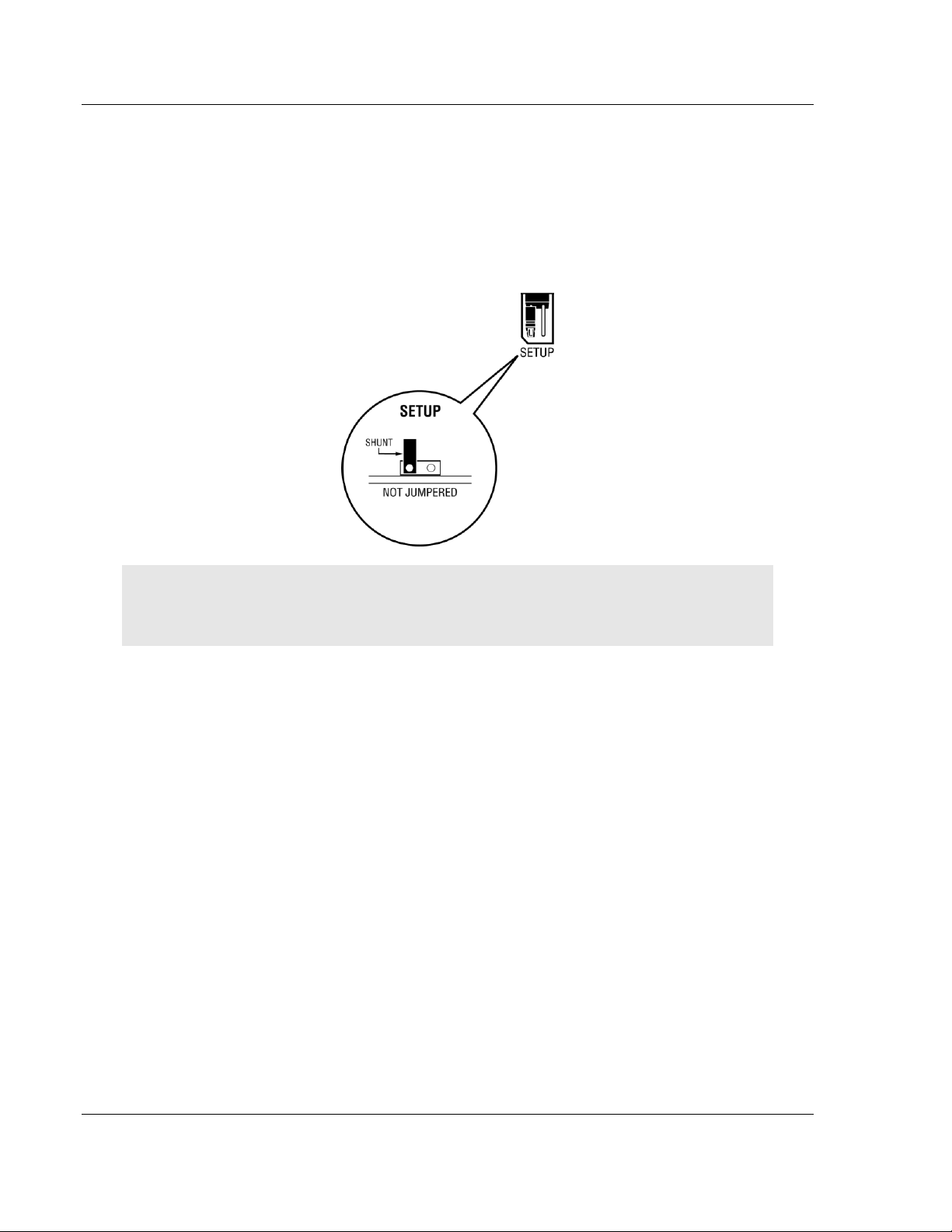
1.4 Setting Jumpers
The Setup Jumper acts as "write protection" for the module’s flash memory. In
"write protected" mode, the Setup pins are not connected, and the module’s
firmware cannot be overwritten. Do not jumper the Setup pins together unless
you are directed to do so by ProSoft Technical Support.
The following illu stration shows the MVI56-104S jumper configu ration.
Note: If you are installing the module in a remote rack, you may prefer to leave the Setup pins
jumpered. That way, you can update the module’s firmware without requiring physical access to
the module.
Page 12 of 188 ProSoft Technolo gy, Inc .
November 18, 2009
Page 13
Start Here MVI56-104S ♦ ControlLogix Platform
User Manual IEC 60870-5-104 Server Communication Module
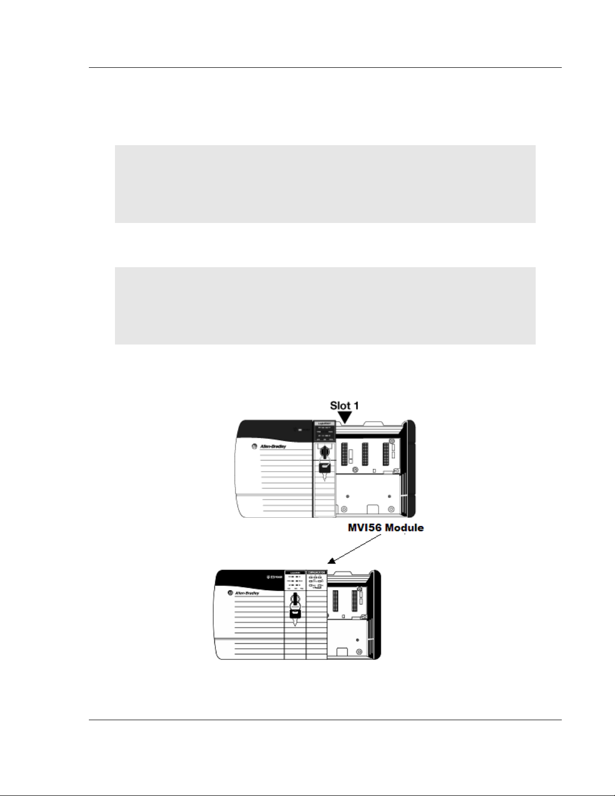
1.5 Install the Module in the Rack
If you have not already installed and configured your ControlLogix processor and
power supply, please do so before installing the MVI56-104S module. Refer to
your Rockwell Automation product documentation for installa tion instructions.
Warning: You must follow all safety instructions when installing this or any other electronic
devices. Failure to follow safety procedures could result in damage to hardware or data, or even
serious injury or death to personnel. Refer to the documentation for each device you plan to
connect to verify that suitable safety procedures are in place before installing or servicing the
device.
After you have checked the placement of the jumpers, insert MVI56-104S into
the ControlLogix chassis. Use the same technique recommended by Rockwell
Automation to remove and install ControlLogix modules.
Warning: When you insert or remove the module while backplane power is on, an electrical arc
can occur. This could cause an explosion in hazardous location installations. Verify that power is
removed or the area is non-hazardous before proceeding. Repeated electrical arcing causes
excessive wear to contacts on both the module and its mating connector. Worn contacts may
create electrical resistance that can affect module operation.
1 Turn power OF F.
2 Align the module with the top and bottom guides, and slide it into the rack
until the module is firmly against the backplane connector.
3 With a firm but steady push, snap the module into place.
ProSoft Technolo gy, Inc . Page 13 of 188
November 18, 2009
Page 14
MVI56-104S ♦ ControlLogix Platform Start Here
IEC 60870-5-104 Server Communication Module User Manual
4 Check that the holding clips on the top and bottom of the module are securely
in the locking holes of the rack.
5 Make a note of the slot location. You must identify the slot in which the
module is installed in order for the sample program to work correctly. Slot
numbers are identified on the green circuit board (backplane) of the
ControlLogix rack.
6 Turn power ON.
Note: If you insert the module improperly, the system may stop working, or may behave
unpredictably.
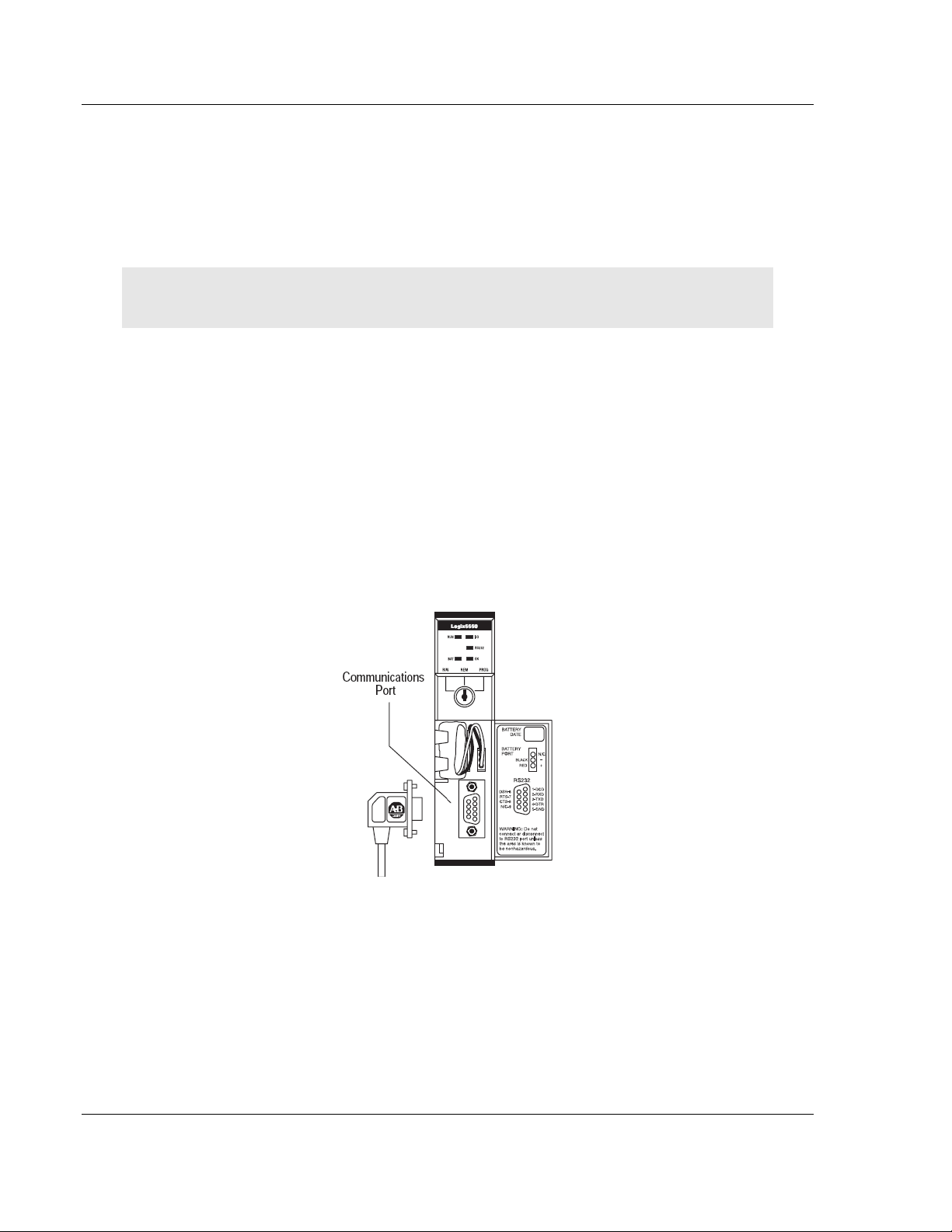
1.6 Connect your PC to the ControlLogix Processo r
There are several ways to establish communication between your PC and the
ControlLogix processor. The following steps show how to establish
communication through the serial interface. It is not mandatory that you use the
processor's serial interface. You may access the processor through whatever
network interface is available on your system. Refer to your Rockwell Automation
documentation for information on other connection methods.
1 Connect the right-angle connector end of the cable to your controller at the
communic ati o ns por t.
Page 14 of 188 ProSoft Technolo gy, Inc .
November 18, 2009
Page 15

Start Here MVI56-104S ♦ ControlLogix Platform
User Manual IEC 60870-5-104 Server Communication Module
2 Connect the straight connector end of the cable to the serial port on your
computer.
1.7 Open the Sample Ladder Logic
The sample program for your MVI56-104S module includes custom tags, data
types and ladder logic for data I/O and status monitoring. For most applications,
you can run the sample ladder program without modification, or, for advanced
applications, you can incorporate the samp le program into your existing
application.
The inRAx Solutions CD provides on e or more v ersions of the sample lad der
logic. The versi o n num b er appended to the file na m e corresponds with the
firmware vers i o n number of your Control Lo gi x pr o c ess or . Th e firm w ar e ver s i o n
and sample program version must match.
1.7.1 To Determine the Firmware Version of your Processor
Important: The RSLinx service must be installed and running on your computer in order for
RSLogix to communicate with the processor. Refer to your RSLinx and RSLogix documentation for
help configuring and troubleshooting these applications.
1 Connect an RS-232 serial cable from the COM (serial) port on your PC to the
communication port on the front of the pr ocessor.
2 Start RSLogix 5000 and close any existing project that may be loaded.
3 Open the Communications menu and choose Go Online. RSLogix will
establish communication with the processor. This may take a few moments.
ProSoft Technolo gy, Inc . Page 15 of 188
November 18, 2009
Page 16
MVI56-104S ♦ ControlLogix Platform Start Here
IEC 60870-5-104 Server Communication Module User Manual
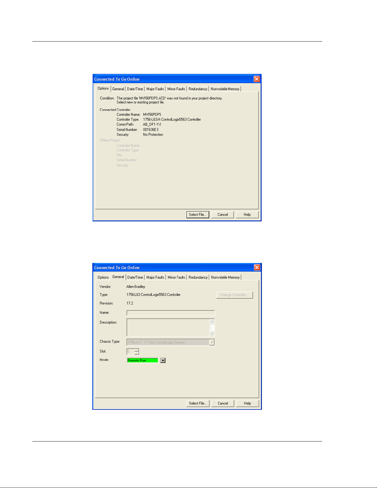
4 When RSLogix has est a blished communica tion wit h the processor, the
Connected To Go Online dialog box will open.
5 On the Connected To Go Online dialog box, click the General tab. This tab
shows information about the processor, including the Revision (firmware)
version. In the following illustration, the firmwa re version is 17.2.
Page 16 of 188 ProSoft Technolo gy, Inc .
November 18, 2009
Page 17
Start Here MVI56-104S ♦ ControlLogix Platform
User Manual IEC 60870-5-104 Server Communication Module
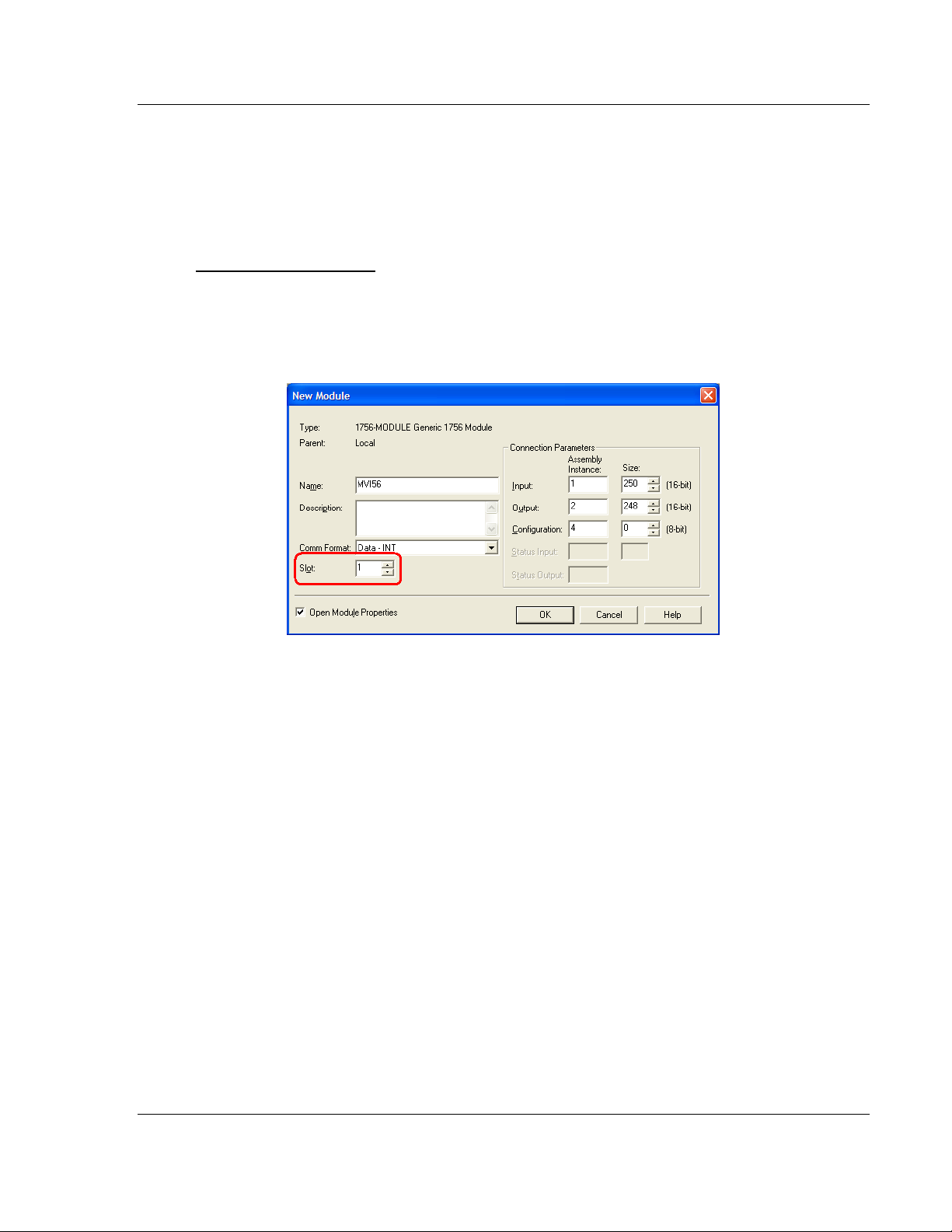
1.7.2 Select the Slot Number for the Modu le
The sample application is for a module installed in Slot 1 in a ControlLogix rack.
The ladder logic uses the slot number to identify the module. If you are installing
the module in a different slot, you must update the ladder logic so that program
tag s and variables ar e corre ct, and do not conflict with othe r m odules in the rack.
To change the slot number
1 In the Controller Organization list, select the module [1] 1756-MODULE
MVI56, and then click the right mouse button to open a shortcut menu.
2 On the shortcut menu, choose Properties. This action opens the Module
Properti es di alog box.
3 In the Slot: field, use the spinners on the right side of the field to select th e
slot number where the module will reside in the rack, an d the n click OK.
RSLogix will automatically app ly the slot number change to all tags, variables
and ladder logic rungs that use the MVI56-104S slot number for computation.
ProSoft Technolo gy, Inc . Page 17 of 188
November 18, 2009
Page 18
MVI56-104S ♦ ControlLogix Platform Start Here
IEC 60870-5-104 Server Communication Module User Manual
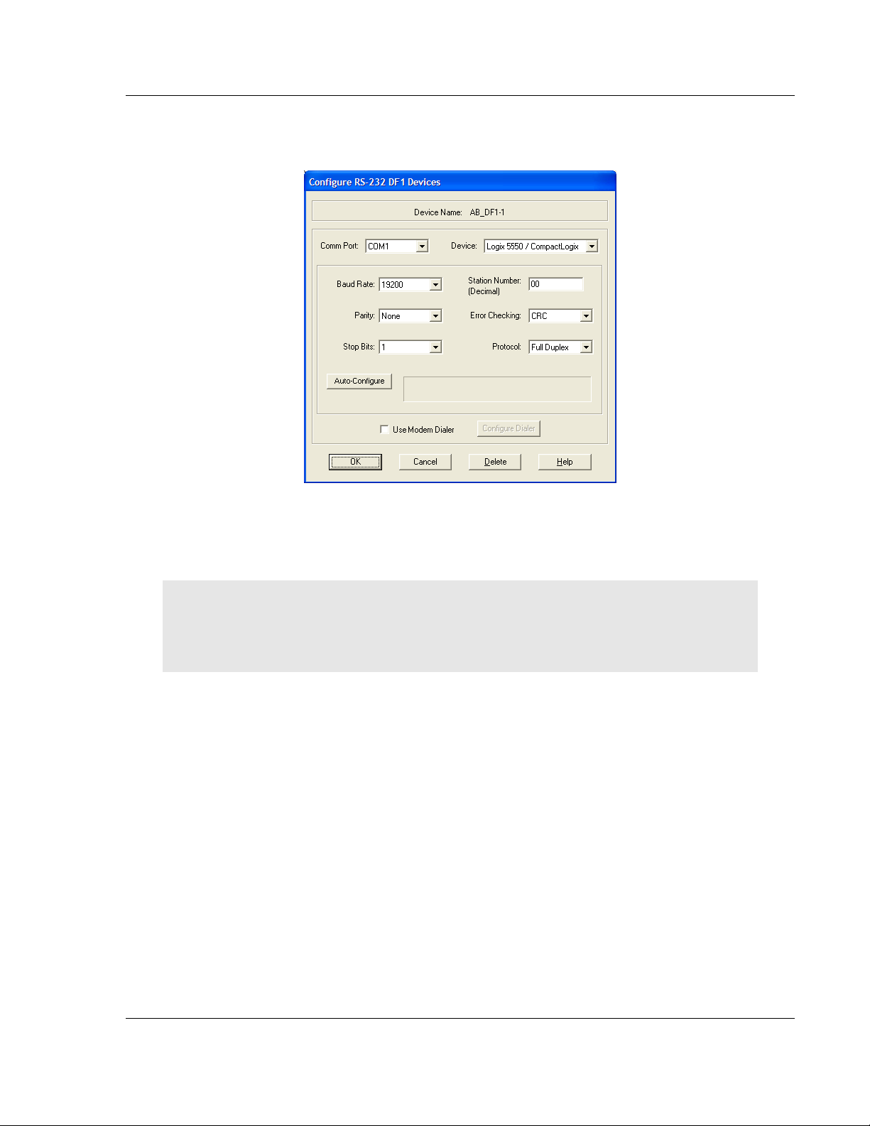
1.7.3 Configuring the RSLinx Driver for the PC COM Port
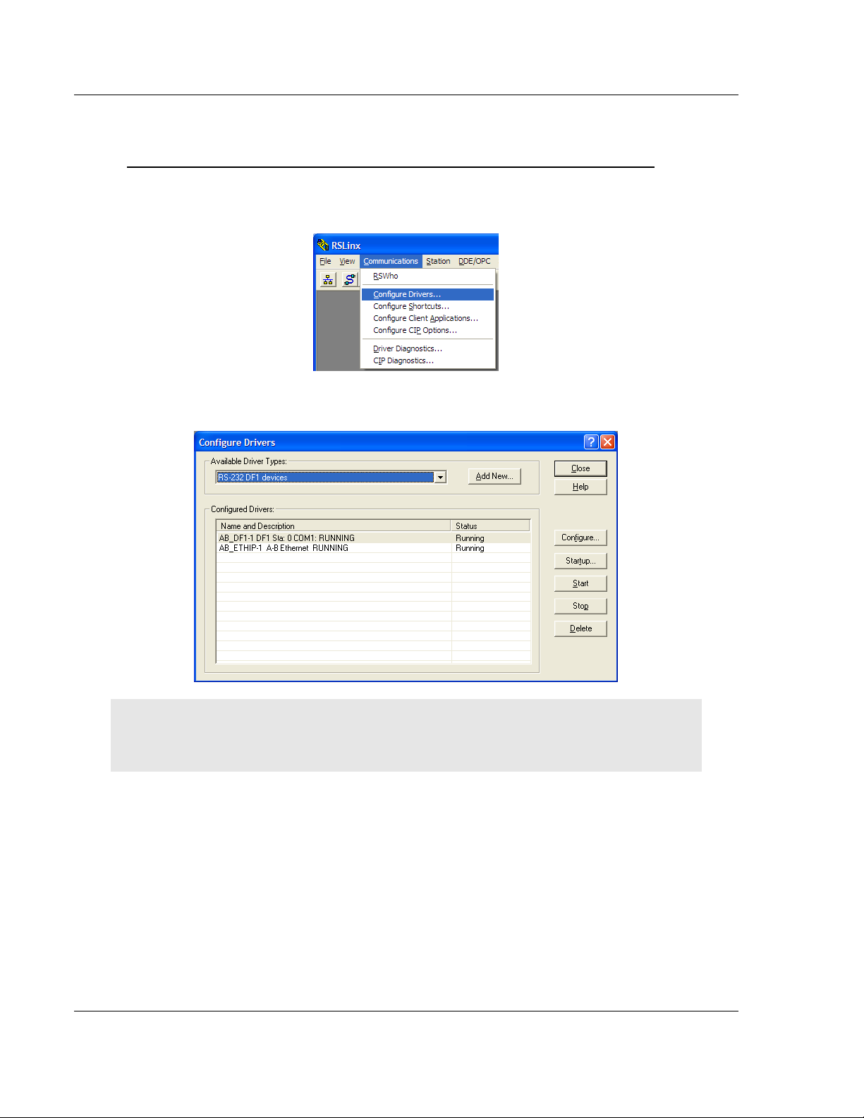
If RSLogix is unable to establish communication with the processor, follow these steps
1 Open RSL
2 Open the C
This action opens the C
INX.
OMMUNICATIONS menu, and choose CONFIGURE DRIVERS.
ONFIGURE DRIVERS dialog box.
Note: If the list of configured drivers is blank, you must first choose and configure a driver from the
Available Driver Types list. The recommended driver type to choose for serial communication with
the processor is RS-232 DF1 DEVICES.
Page 18 of 188 ProSoft Technolo gy, Inc .
November 18, 2009
Page 19
Start Here MVI56-104S ♦ ControlLogix Platform
User Manual IEC 60870-5-104 Server Communication Module
3 Click to select the driver, and then click C
C
ONFIGURE RS-232 DF1 DEVICE dialog box.
ONFIGURE. This action opens the
4 Click the A
UTO-CONFIGURE button. RSL inx will attempt to configure your
serial port to work with the selected driver.
5 When you see the message A
UTO CONFIGURATION SUCCESSFUL, click the OK
button to dismiss the dialog box.
Note: If the auto-configuration procedure fails, verify that the cables are connected correctly
between the processor and the serial port on your computer, and then try again. If you are still
unable to auto-configure the port, refer to your RSLinx documentation for further troubleshooting
steps.
ProSoft Technolo gy, Inc . Page 19 of 188
November 18, 2009
Page 20
MVI56-104S ♦ ControlLogix Platform Start Here
IEC 60870-5-104 Server Communication Module User Manual
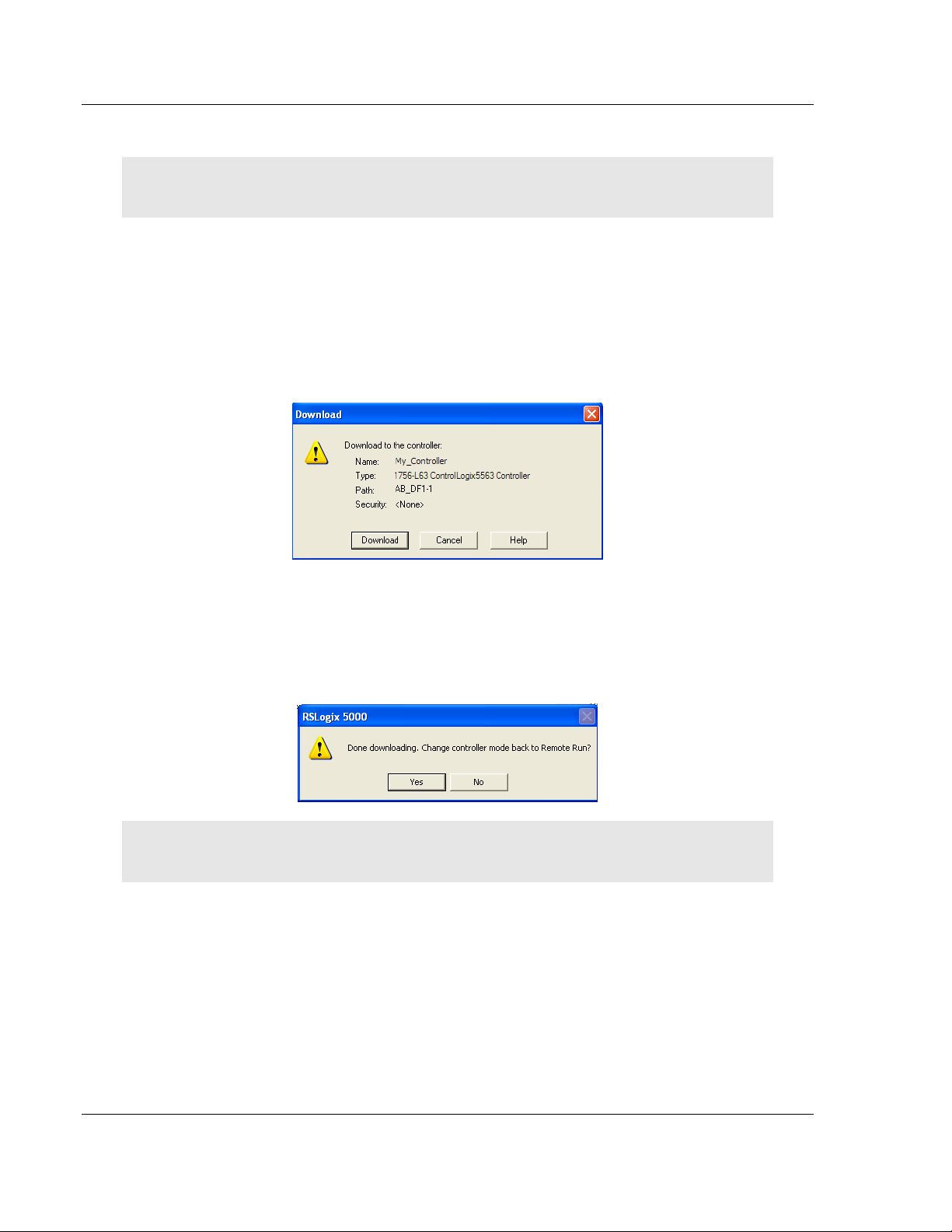
1.8 Download the Sample Program to the Processor
Note: The key switch on the front of the ControlLogix processor must be in the REM or PROG
position.
1 If you are not already online with the pr oc e ss or , o pe n the COMMUNICATIONS
menu, and then choose DOWNLOAD. RSLogix will estab lish communication
with the processor. You do not hav e to download through the pr ocessor's
serial por t, as shown here. You may dow nl o ad through any available network
connection.
2 When co mmunication is established, RS Logix will open a confirmation dialog
box. Click the D
processor.
OWNLOAD button to transfer the sample program to the
3 RSLogix will compile the program and t ransfe r it to the processor. This
process may take a few minutes.
4 When the download is complete, RSLogi x will open another confirmation
dialog box. If the key switch is in the REM position, click OK
process or fr om P
ROGRAM mode to RUN mode.
to switch the
Note: If you receive an error message during these steps, refer to your RSLogix documentation to
interpret and correct the error.
Page 20 of 188 ProSoft Technolo gy, Inc .
November 18, 2009
Page 21
Start Here MVI56-104S ♦ ControlLogix Platform
User Manual IEC 60870-5-104 Server Communication Module
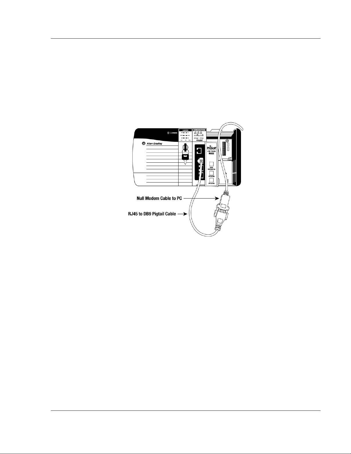
1.9 Connect your PC to the Module
With the module securely mounted, connect your PC to the
Configuration/Debug port using an RJ45-DB-9 Serial Adapter Cable and a Null
Modem Cable.
1 Attach both ca bl es as s hown.
2 Insert the RJ45 cable connector into the Configuration/Debug port of the
module.
3 Attach the other en d to the serial port on your PC.
ProSoft Technolo gy, Inc . Page 21 of 188
November 18, 2009
Page 22

MVI56-104S ♦ ControlLogix Platform Start Here
IEC 60870-5-104 Server Communication Module User Manual
Page 22 of 188 ProSoft Technolo gy, Inc .
November 18, 2009
Page 23

Configuring the MVI56-104S Module MVI56-104S ♦ ControlLogix Platform
User Manual IEC 60870-5-104 Server Communication Module
2 Configuring the MVI56-104S Modul e
In This Chapter
Using ProSoft Configuration Builder ...................................................23
[Backplane Configuration]..................................................................28
[SNTP CLIENT] .................................................................................30
[IEC-870-5-104] .................................................................................32
[IEC-870-5-104 IP Addresse s]............................................................38
[IEC-870-5-104 Database] .................................................................39
[M_SP_NA_1 104].............................................................................43
[M_DP_NA_1 104] .............................................................................43
[M_ST_NA_1 104].............................................................................43
[M_ME_NA_1 104] ............................................................................44
[M_ME_NB_1 104] ............................................................................44
[M_ME_NC_1 104]............................................................................45
[M_IT_NA_1 104] ..............................................................................45
[C_SC_NA_1 104].............................................................................46
[C_DC_NA_1 104].............................................................................46
[C_RC_NA_1 104].............................................................................47
[C_SE_NA_1 104] .............................................................................47
[C_SE_NB_1 104] .............................................................................48
[C_SE_NC_1 104].............................................................................48
Group Codes.....................................................................................49
Ethernet Configuration.......................................................................50
Download the Project to the Module...................................................51
Adding the Module to an Existing Project............................................52
2.1 Using ProSoft Configuration Builder
ProSoft Configuration Builder (PCB) pr ovi d es a qu i ck and easy way to man ag e
module configuration files customized to meet your application needs. PCB is not
only a powerful solution for new configuration files, but also allows you to import
information from previously installed (known working) configurations to new
projects.
ProSoft Technolo gy, Inc . Page 23 of 188
November 18, 2009
Page 24
MVI56-104S ♦ ControlLogix Platform Configuring the MVI56-104S Module
IEC 60870-5-104 Server Communication Module User Manual
2.1.1 Set Up the Project
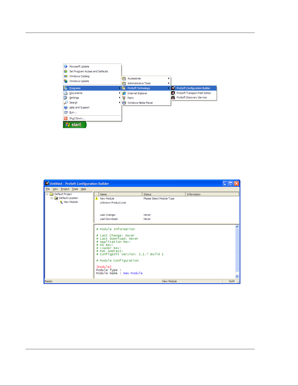
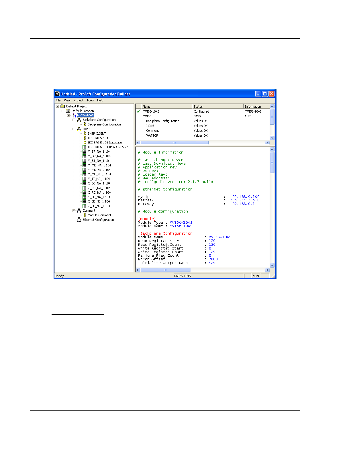
To begin, start PROSOFT CONFIGURATION BUILDER (PCB).
If you have used other Windows configuration too ls before, you will find the
screen layout familiar. PCB’s window consists of a tree view on the left, and an
information pane and a configuration pane on the right side of the window. When
you first star t PCB, the tree view consists of fol ders for D
D
EFAULT LOCATION, with a DEFAULT MODULE in the Default Location folder. The
following illustration shows the PCB window with a new project.
EFAULT PROJECT and
Page 24 of 188 ProSoft Technolo gy, Inc .
November 18, 2009
Page 25
Configuring the MVI56-104S Module MVI56-104S ♦ ControlLogix Platform
User Manual IEC 60870-5-104 Server Communication Module
To add the MVI56-104S module to the project:
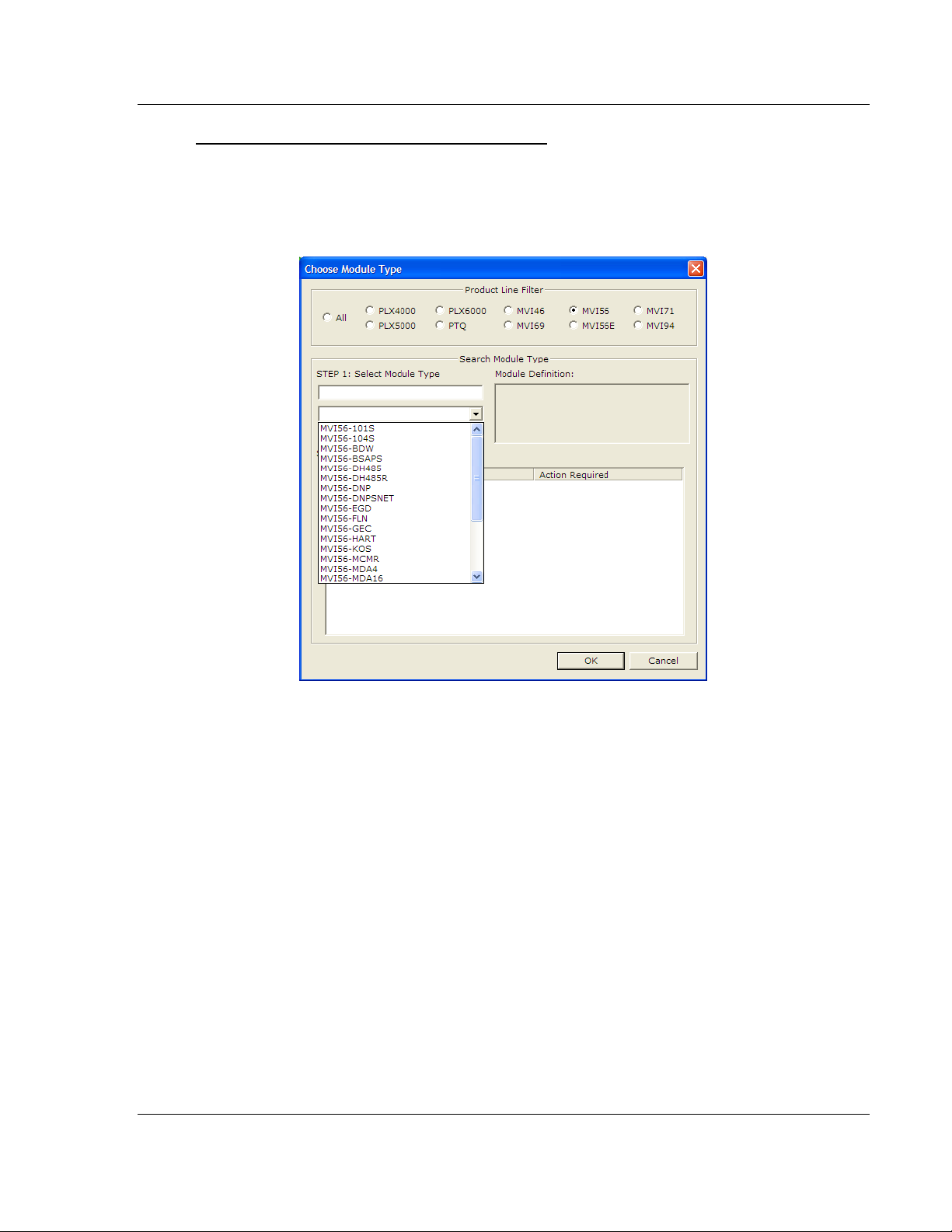
1 Use the mouse to select D
EFAULT MODULE in the tree view, and then clic k the
right mouse button to open a shortcut menu.
2 On the shortcut menu, choose C
HOOSE MODULE TYPE. This actio n op ens the
CHOOSE MODULE TYPE dialog box.
3 In the P
S
ELECT MODULE TYPE dropdown list, select MVI56-104S, and then click OK
RODUCT LINE FILTER area of the dialog box, select MVI56. In the
to save your settings and return to the ProSoft Configuration Builder window.
ProSoft Technolo gy, Inc . Page 25 of 188
November 18, 2009
Page 26
MVI56-104S ♦ ControlLogix Platform Configuring the MVI56-104S Module
IEC 60870-5-104 Server Communication Module User Manual
2.1.2 Set Module Parameters
The next task is to configure module parameters. Notice that the contents of the
information pane and the configuration pane changed when you added the
MVI56-104S module to the project.
At this time, you may wish to rename the "Default Project" and "Default Location"
folders in the tree view.
To rename an object:
1 Select the object, and then click the right mouse button to open a shortcut
menu. From the shortcut menu, choose R
ENAME.
2 Type the name to assi gn to the object.
3 Click away from the object to save the new name.
Page 26 of 188 ProSoft Technolo gy, Inc .
November 18, 2009
Page 27
Configuring the MVI56-104S Module MVI56-104S ♦ ControlLogix Platform
User Manual IEC 60870-5-104 Server Communication Module
To Configure Module Parameters
1 Click on the plus sign next to the
2 Double-click the
icon to open the EDIT dialog box.
icon to expand module information.
3 To edi t a parameter , select the parameter in the left pane and make your
changes in the right pane.
4 Click OK
to save your changes.
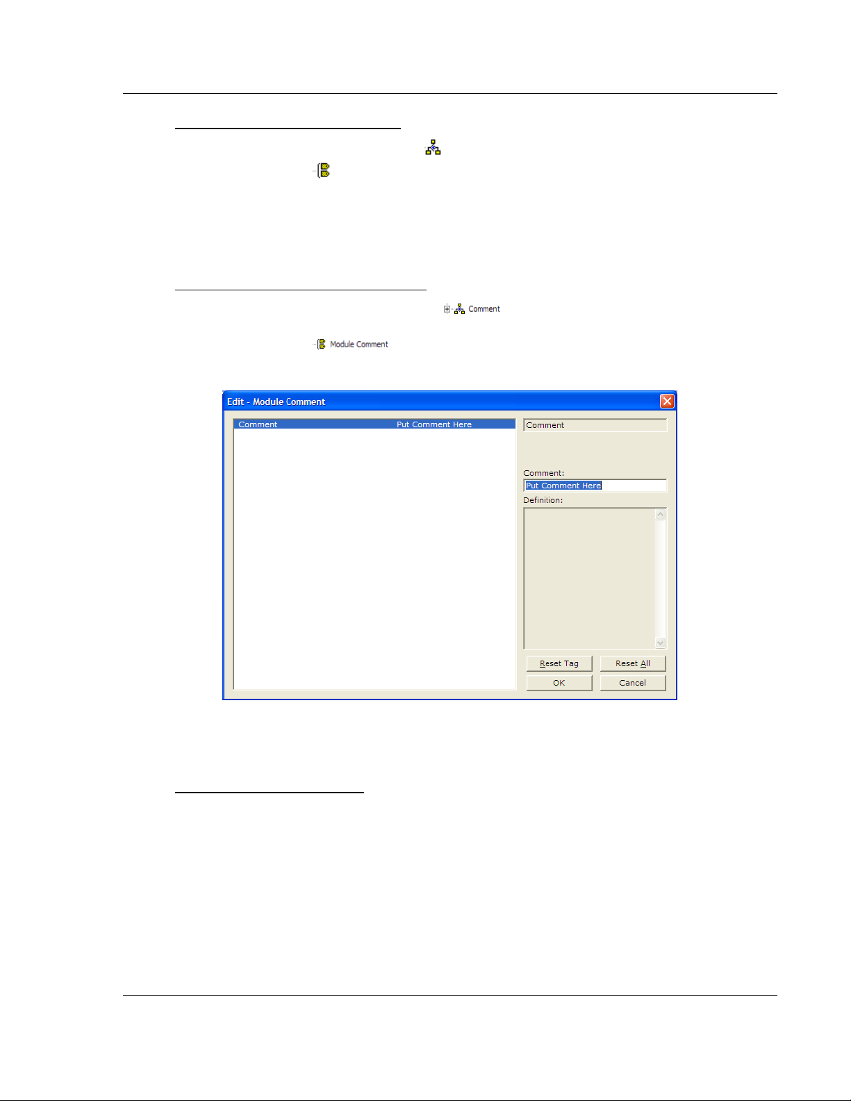
To Create Optional Comment Entrie s
1 Click the plus sign to the left of the
icon to expand the module
Comments.
2 Double-click the
icon. The EDIT - MODULE COMMENT dialog
appears.
3 Enter your comment and click OK
to save your changes.
Printing a Configuration File
1 Select the M
ODULE icon, and then click the right mouse button to open a
shortcut menu.
2 On the shortcut menu, choose V
V
IEW CONFIGURATION window.
3 On the V
P
RINT. This action opens the PRINT dialog box.
4 On the P
IEW CONFIGURATION window, open the FILE menu, and choose
RINT dialog box, choos e th e printer to use from the dropd ow n list,
select printing options, and then click OK.
IEW CONFIGURATION. This action opens the
ProSoft Technolo gy, Inc . Page 27 of 188
November 18, 2009
Page 28

MVI56-104S ♦ ControlLogix Platform Configuring the MVI56-104S Module
IEC 60870-5-104 Server Communication Module User Manual
2.2 [Backplane Configuration]
This section provides the module with a unique name, identifies the method of
failure for the communications for the module if the processor is not in run, and
describes how to initialize the module upon startup.
2.2.1 Module Name
0 to 80 characters
This parameter assigns a name to the module that can be viewed using the
configuration/debug port. Use this parameter to identify the module and the
configuration file.
2.2.2 Read Register Start
Range 0 to 39 99
This parameter specifies the starting register in the module where data will be
transferred from the module to the processor. Valid range for this parameter is 0
to 3999.
2.2.3 Read Register Count
0 to 4000
The Read Register Count parameter defines the size of the module’s input
database, up to a maximum value of 4000 words.
2.2.4 Write Register Start
0 to 3999
This parameter specifies the starting register in the module where the data will be
transferred from the processor to the module.
2.2.5 Read Register Count
0 to 4000
The Read Register Count parameter defines the size of the module’s input
database, up to a maximum value of 4000 words.
Page 28 of 188 ProSoft Technolo gy, Inc .
November 18, 2009
Page 29

Configuring the MVI56-104S Module MVI56-104S ♦ ControlLogix Platform
User Manual IEC 60870-5-104 Server Communication Module
2.2.6 Failure Flag Count
0 through 65535
This paramete r specifies the number of su ccessive transfer errors that must
occur before halting communication on the application port(s). If the parameter is
set to 0, the application port(s) will cont inu e to operate under all conditions. If the
value is set larger than 0 (1 to 65535), communication s will cease if the specified
number of failures occur.
2.2.7 Error Offset
0 to 3980, or -1 to disable
This parameter specifies the database location where to write status data.
2.2.8 Initialize Output Data
Yes or No
This parameter determines if the output data for the module should be initialized
with values from the processor. If the value is set to No (0), the output data will
be initialized to 0. If the value is set to Yes (1), the data will be initialized with
data from the processor. Use of this option requires associated ladder logic to
pass the dat a fr om the pr oc es sor to th e mo dule.
ProSoft Technolo gy, Inc . Page 29 of 188
November 18, 2009
Page 30
MVI56-104S ♦ ControlLogix Platform Configuring the MVI56-104S Module
IEC 60870-5-104 Server Communication Module User Manual
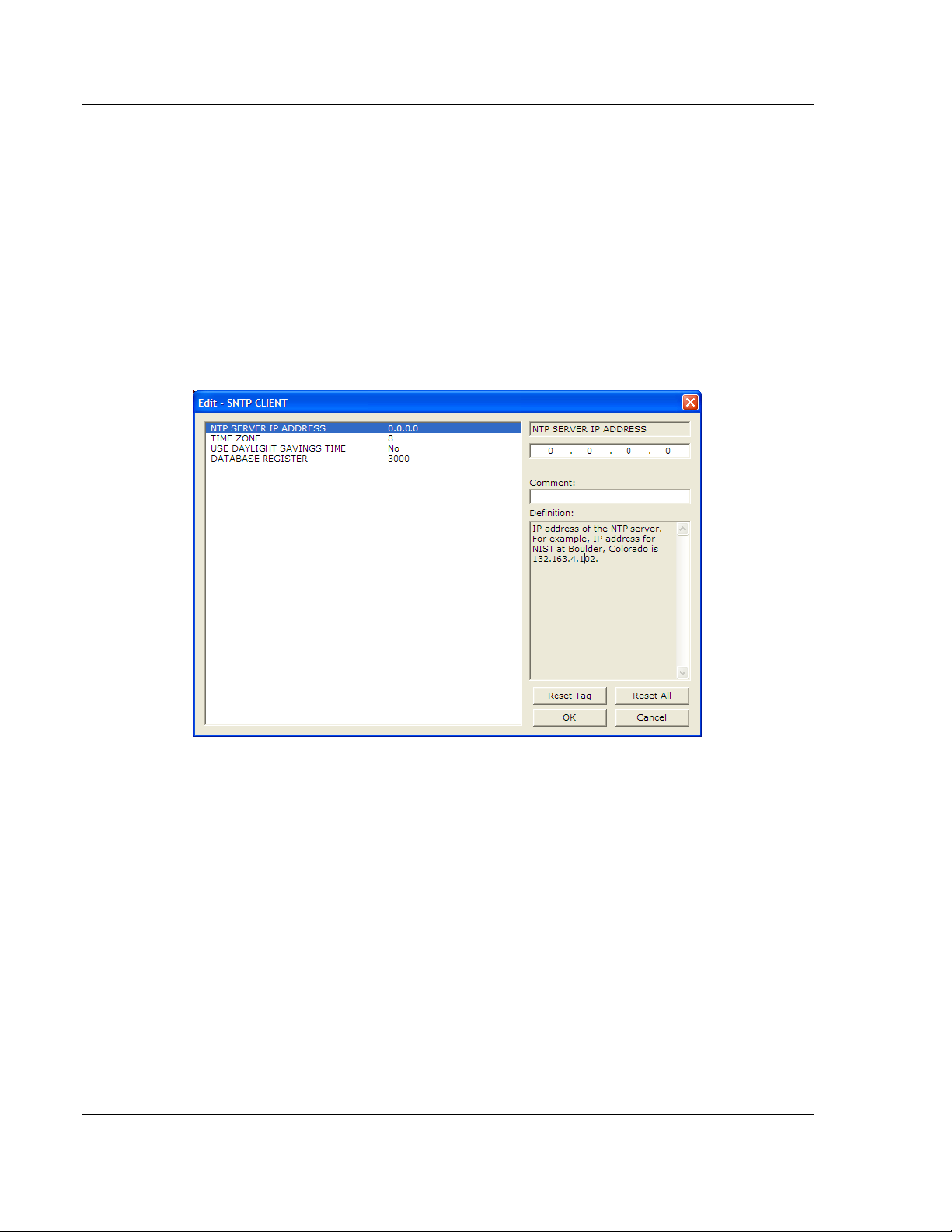
2.3 [SNTP CLIENT]
The [SNTP CLIENT] section of the CFG file is used to speci fy th e par ameters for
the Simple Network Time Protocol (SNTP) client provided with the protocol
driver. This client is required in order to keep the driver's internal clock set
correctly. This version of the driver supports SNTP Revision 3 and stratum
bet ween 1 and 14.
SNTP is used for time synchronization of produced and consumed commands.
When an exchan ge occurs the driver compa res time s tamps from the previo us
exchange. When the new exchange time is less than the previous exchange, the
exchange is ignored. This can occur when the Ethernet packets are routed and
delayed . Tim e sy nc hr oni zation provides for dat a i n tegr i ty .
The SNTP driver will compute a new clock value every 5 minutes using the
average val ue of 10 samples each collec t ed over an ap pr oxi m a t e 6- second
period. This new value will be used to adjust the clock maintained by the SNTP
driver and used by the application. If a valid database register is specified, the
driver will place the time value into the module's database. The first two registers
will contain the number of seconds and the next two registers will contain the
number of microseconds since January 1, 1970.
A list of some of the common NTP servers can be obtained at
http://www.ntp.org/, http://www.eecis.udel.edu/~mills/ ntp/servers.html, along with
the appropriate IP address. Other server lists can be found by searching the
World Wide Web for "NTP Servers".
Page 30 of 188 ProSoft Technolo gy, Inc .
November 18, 2009
Page 31

Configuring the MVI56-104S Module MVI56-104S ♦ ControlLogix Platform
User Manual IEC 60870-5-104 Server Communication Module
2.3.1 NTP Server IP Address
Enter in dotte d notation
This parameter sets the IP add ress of the NTP server to utilize for time
acquisition. Select an NTP server with the greatest accuracy that can be
accessed all the time from your network. Setting this IP address to 0.0.0.0
disables SNTP server requests.
2.3.2 Time Zone
-11 to 11
This parameter specifies the time zone offset to be used from the UTC time
zone. A value of zero uses UTC time. If the value entered is positive, the time
zone is west of the UTC time zone (that is, Eastern Standard Time is 5). If the
value entere d is negative, the time zone is east of the UTC time zone (that is,
Continenta l Europe is -1).
2.3.3 Use Daylight Savings Time
Yes or No
This parameter specif ies if dayligh t saving s time will be used in the time
computation.
2.3.4 Database Register
-1 or 0 to 3992 as an eve n val u e
This parameter specifies if the NTP time computed by the driver is to be placed
into the module’s database. If a value of -1 is specified, the time will not be
placed into the database. If the value is between 0 and 3992, the time will be
placed in the database. The first 4 bytes will represent the seconds since
1/1/1970, and the second 4 byte s will represent the number of microseconds. An
even value should be used for the register value in order for the data to be stored
correctly.
ProSoft Technolo gy, Inc . Page 31 of 188
November 18, 2009
Page 32

MVI56-104S ♦ ControlLogix Platform Configuring the MVI56-104S Module
IEC 60870-5-104 Server Communication Module User Manual
2.4 [IEC-870-5-104]
This section provides information required to configure a server application with
the module. Most entries contained within this section are self explanatory An
item of concern is the maximum size of the total database, although it is possible
to configure a database of considerable size, this would not work, as the
maximum Class 0 request may not exceed 2048 bytes in size.
2.4.1 Use IP List
0 or 1
This parameter specifies if the IP address of the host connected to the system
will be validated. If the parameter is set to 0, any host may connect to the unit. If
the parameter is set to 1, only hosts in the IP list will be permitt ed to connect to
the unit.
2.4.2 Override StartDT
0 or 1
This parameter is used when testing th e unit with a simulator or with a client unit
that does not meet the IEC 60870-5-104 specification. After the host connects to
the system, it will send a STARTDT.ACT U-format message to the unit to permit
the un it to s tart sending data. If the client does not support t his requirement, set
the parameter to a value of 1. Set the paramete r to 0 if the unit sends the
STARTDT.ACT message.
Page 32 of 188 ProSoft Technolo gy, Inc .
November 18, 2009
Page 33

Configuring the MVI56-104S Module MVI56-104S ♦ ControlLogix Platform
User Manual IEC 60870-5-104 Server Communication Module
2.4.3 Clear Queue on Close
0 or 1
Use this command to define whether the module will store the una c knowledged
buffers in the unit after the connection is closed. If the specification is to be
followed, set this parameter to 0 and the packet s will be resent after a connection
is made. If you want to flush the packets after the connection is closed, set this
parameter to 1 (this is not according to the IEC 60870-5-104 specification).
2.4.4 t1 Timeout Set Value
1 to 255
This is the timeout of send or test ASDUs and is in units of seconds. After a
packet is sent from the unit, the client must acknowledge the pa cket within this
time interval or else the unit will close the connection.
2.4.5 t2 Timeout Set Value
1 to 255
This is a timeout of when to send an S-format message to the host to
acknowledge outstanding messages received. This parameter is in units of
seconds and must be less than the value set for t1.
2.4.6 t3 Timeout Set Value
1 to 255
This is the timeout to wait on an idle line before the unit will send a TestFr.Act
message. This value is in units of seconds.
2.4.7 k (maximum queue)
1 to 20
This parameter spec ifies the number of unacknowledged messages th e unit will
buffer. Th is parameter must match that in the host. If the se t number of buffers
are filled in the unit, no other me ssage s will be sent un t il the host unit
acknowledges some or all the messages.
ProSoft Technolo gy, Inc . Page 33 of 188
November 18, 2009
Page 34

MVI56-104S ♦ ControlLogix Platform Configuring the MVI56-104S Module
IEC 60870-5-104 Server Communication Module User Manual
2.4.8 w (latest ack threshold)
1 to 20
This parameter must match that of the host unit and specifies the number of
messages the module will receive before sending an S-format sequence
acknowledge message when no I-format data is ready to send. It is
recommended to set this value to 2/3 the value of k.
2.4.9 Time DB Offset
-1 or 0 to 3994
This parameter sets the lo cation in the database where the module’s current date
and time will be copied to.
Note: The following tables lists the 12 byte, data area placed in the database if the Time DB Offset
parameter is set to a value other than -1:
Byte Length Range Description
0 to 1 2 0 to 59,999 Seconds and m il li seconds
2 1 0 to 59 Minutes
3 1 0 to 23 Hour
4 1 Reserved
5 1 1 to 31 Day of the Month
6 1 1 to 12 Month
7 to 8 2 0 to 65,535 Year (four digit format, for example 2005)
9 1 Reserved
10 1 0 or 1 Invalid Flag (0 = Valid, 1 = Invalid
11 1 Reserved
2.4.10 Err or Offset
0 to 3980
-1 to disable
This parameter sets the location in the module’s internal database when the
status and error information for the server will be stored. En ter a va lid database
address of 0 to 3980 to store the information, or enter -1 to disable.
Page 34 of 188 ProSoft Technolo gy, Inc .
November 18, 2009
Page 35

Configuring the MVI56-104S Module MVI56-104S ♦ ControlLogix Platform
User Manual IEC 60870-5-104 Server Communication Module
2.4.11 Comm on Address of ASDU
0 to 65535
This parameter specifies the comm o n ad dr ess o f t he ASDU (s ec ti o n ad dr ess ) for
access to data in the module. There is only one value entered for access to all
data in the module.
2.4.12 Cyclic Data Transmission
0 to 2^32
This parameter defines the number of millise c on ds between cyclic updates. The
range of values for this parameter permit upda te times of 1 millisecond to 5
minutes. If the parameter is set to 0, cyclic data reporting will be disabled.
2.4.13 Select/Oper ate Timeout
0 to 2^32
This parameter sets the numbe r of milliseconds after a select command is
received in which to wait for a valid execute command. The range of values for
this parameter permit times of 1 millisec on d to 30 second s. If the parameter is
set to 0, the feature will be disabled.
2.4.14 Use ACTTERM with Setpoint
1 or 0
This parameter determines if an ACTTERM will be sent. If the parameter is set to
1, then setpoint commands will issue an ACTTERM when the command is
complete. If the parameter is set to 0, ACTCON is the last response to a setpoint
command.
2.4.15 Use ACTTERM with Step
1 or 0
This parameter determines if an ACTTERM will be sent. If the parameter is set to
1, then step commands will issue an ACTTERM when the command is complete.
If the parameter is set to 0, ACTCON is the last response to a step command.
ProSoft Technolo gy, Inc . Page 35 of 188
November 18, 2009
Page 36

MVI56-104S ♦ ControlLogix Platform Configuring the MVI56-104S Module
IEC 60870-5-104 Server Communication Module User Manual
2.4.16 Freeze Start Type
D=Day, H=Hour, M=Minute, N=Not used
The Freeze Start Type parameter defines when the module starts sending the
M_IT messages.
2.4.17 Interval for Freeze
0 to 65535
Freeze Start Type and Interval for Freeze are used if Mode A operation is to be
used for the counter free ze operation. If they are not used, the modu le will
operate in Mode D.
2.4.18 Set Priority Queues
Yes or No
This section defines priority queues for the module. You can assign priorities to
data types that can return events so that events of data types will be returned
before other data types. This may cause events to be lost as the event buffers for
low priority queues may overflo w. If th is feature is utilized, each data type must
be assigned a unique index from 0 to 6. The lower the index, the higher the
priority (0=h ighest priority).
Each of the ASDUs affected by this feature must be assigned a unique priority
index from 0 to 6. Events of the ASDU with a priority of 0 will always be reported
before any others when they are present.
For more information, refer to Event Priority.
Page 36 of 188 ProSoft Technolo gy, Inc .
November 18, 2009
Page 37

Configuring the MVI56-104S Module MVI56-104S ♦ ControlLogix Platform
User Manual IEC 60870-5-104 Server Communication Module
2.4.19 Cyclic Set IV Time
Minimum 3 times larger than IV Check Delay Time parameter
0 to disable
The Cyclic Set IV Time parameter determines how frequently the IV Checks will
be perform ed . If the IV bit is ON for a number o f tim es given by the IV Fail Count
parameter (page 37 ), the module will consider the point as invalid.
If the IV Fail Count para meter is zero, the feature will be disabled.
For more information on using this featu re, ref er to Invalid Bit Monitoring (page
139).
2.4.20 IV Check Delay Time
Value in Seconds
This feature allows the application to set the invalid (IV) quality bit of the protocol
for all the monitored ASDU types supported. The Cyclic Set IV Time parameter
must be at least 3 times larger than the IV Check Delay Time.
2.4.21 IV Fail Count
0 to disable
This feature allows the application to set the invalid (IV) quality bit of the protocol
for all the monitored ASDU types supported. If you enable this feature, the
processor can determine the individual IV quality bit status of each point you
configured.
To disable this feature, set the IV Fail Count parameter to 0. If used, the Cyclic
Set IV Time parameter must be at least 3 times larger than the IV Check Delay
Time.
2.4.22 Event Scan Delay
1 to 65535
0 to disable
If set to 0, the feature will be disabled and the module will n ot gene rate any
events. If set from 1 to 65535, the parameter represents the number of
milliseconds between event scanning. This parameter defines how often the
program will scan for new events in the databases.
ProSoft Technolo gy, Inc . Page 37 of 188
November 18, 2009
Page 38

MVI56-104S ♦ ControlLogix Platform Configuring the MVI56-104S Module
IEC 60870-5-104 Server Communication Module User Manual
2.4.23 Scan Events
Scan for Event s
No Scanning
Defines whether event s of this po int type will be generated by the module. If "No
Scanning", th en events will not be generated. If "Sca n for events", events will be
scanned and generated on change.
2.4.24 Time Type
None, CP24 or CP56
This parame ter de fi nes the time form at use d with data events. 0=None, 1=CP24
and 2=CP56 time formats.
2.5 [IEC-870-5-104 IP Addresses]
This section enters the IP addresses for the hosts to connect to this unit. The unit
will only accept connections from hosts listed here. This list may contain up to 10
entries between the START and END labels. The address must start in column 1,
and must be entered in standa rd dot notation.
The following is an example of the [IEC-870-5-104 IP Addresses] section:
Page 38 of 188 ProSoft Technolo gy, Inc .
November 18, 2009
Page 39

Configuring the MVI56-104S Module MVI56-104S ♦ ControlLogix Platform
User Manual IEC 60870-5-104 Server Communication Module
2.6 [IEC-870-5-104 Database]
This section describes the [IEC-870-5-104 Database] section.
2.6.1 Short Pulse Time
0 to 2,147,483,647 millisecon ds
This parameter defines the number of milliseconds to be associated with a short
pulse command.
2.6.2 Long Pulse Time
0 to 2,147,483,647
This parameter def ines the number of milliseconds to be associated with a long
pulse command.
ProSoft Technolo gy, Inc . Page 39 of 188
November 18, 2009
Page 40
MVI56-104S ♦ ControlLogix Platform Configuring the MVI56-104S Module
IEC 60870-5-104 Server Communication Module User Manual
2.6.3 Point Count
Point Count configuration ranges in the following configuration items are based
on the assumption that you will be using only one of the available data types for
your application. The number of point counts you configure will have an effect on
module performance, in particular the accuracy of the module’s internal clock.
M_SP_NA point count: This parameter s p ecifies the number of point v alu es
assigned in monitored single-point databa se. Range is 0 to 1000.
M_DP_NA point count: Thi s parameter specifies the number of po int values
assigned in monitored du al-poi nt database. R ange is 0 to 1000 .
M_ST_NA point count: This parameter specifies the number of point value s
assigned in monitored step-point database. Range is 0 to 1000.
M_ME_NA point count: This parameter specifies the number of point values
assigned in monitored normalized-point database. Range is 0 to 1000.
M_ME_NB point count: This parameter specifies the number of point values
assigned in monitored scaled-point database. Range is 0 to 1000.
M_ME_NC point count: This parameter specifies the number of point values
assigned in monitored scaled short-float point database. Range is 0 to 50.
M_IT_NA point count: This parameter specifies the number of point values
assigned in monitored counter-point database. Range is 0 to 99.
C_SC_NA point count: Thi s parameter specifies the number of point value s
assigne d in com m a nd si ngle-point database. Range is 0 to 10 00 .
C_DC_NA point count: This parameter specifies the number of point values
assigned in command dual-point database. Range is 0 to 1000.
C_RC_NA point count: This parameter specifies the number of point values
assigned in command step-point database. Range is 0 to 1000.
C_SE_NA point count: This parameter specifies the number of point values
assigned in command normalized-point database. Range is 0 to 1000.
C_SE_NB point count: This parameter specifies the number of point values
assigne d in com m a nd sc aled-point databa se. Range is 0 to 10 00.
C_SE_NC point count: This parameter specifies the number of point values
assigne d in com mand short-float point datab ase . R ang e is 0 to 50 .
Page 40 of 188 ProSoft Technolo gy, Inc .
November 18, 2009
Page 41
Configuring the MVI56-104S Module MVI56-104S ♦ ControlLogix Platform
User Manual IEC 60870-5-104 Server Communication Module
2.6.4 Sequence Flag
In order to save bandwidth, you can configure the module to use the Sequence
Flag feature. If this feature is not selected, the module will send the object
address and its value at every monitored response to the master.
If this parameter is selected, the module will turn the Sequen ce Flag on every
monitored response sending the address for the first point along with all point
values. The master assumes that all other points use information object
addresses in a contiguous order (using the first point as the reference).
ProSoft Technolo gy, Inc . Page 41 of 188
November 18, 2009
Page 42

MVI56-104S ♦ ControlLogix Platform Configuring the MVI56-104S Module
IEC 60870-5-104 Server Communication Module User Manual
2.6.5 Parameter Offset
This parameter specifies the IOA (Information Object Address) offset to the
parameter data for the normalized parameter data. The value entered is added to
the Information Object address for th e ass ociated point to compute th e
parameter IOA address.
The Master may send a "Parameter of Measured Normalized" or "Parameter of
Measured Scaled" command using the parameter IOA in order to change the
deadband values for specific points.
Note: The Low Limit and High Limit values are always calculated based on the deadband value as
described in the following table.
Point Value
Threshold Determined by the deadband set in the configuration file or altered by the write
command.
Low Last reported ev ent value - threshold.
High Last reported event value + thr eshold.
For example, if the MVI56-104S configuration sets two M_ME_NA points with
IOA (Point #) o f 600 and 601 and a M_ME_NA Par am eter O f fset v alue of 3000, it
would result in the parameter points shown in the table.
Page 42 of 188 ProSoft Technolo gy, Inc .
November 18, 2009
Page 43

Configuring the MVI56-104S Module MVI56-104S ♦ ControlLogix Platform
User Manual IEC 60870-5-104 Server Communication Module
2.7 [M_SP_NA_1 104]
This section defines the monitored single-point database for the server device
emulated. This information is sourced from the database and is transferred to the
remote client unit. Each point in the database occupies 1 bit (1 = On, 0 = Off
state).
This section takes the following parameters:
Point #
DB Address
Group(s)
IV DB Bit
Each point is one bit and the DB address value corresponds to the bit offset in
the database.
2.8 [M_DP_NA_1 104]
This section defines the monitored dual-point database for the server device
emulated. This information is sourced from the database and is transferred to the
remote client unit. Each point in the database occupies two bits (00 =
intermediate, 01 = off, 10 = on and 11 = intermediate).
This section takes the following parameters:
Point #:
DB Address:
Group(s):
IV DB Bit
Each point is two bits and the DB address value corresponds to the bit offset in
the database.
2.9 [M_ST_NA_1 104]
This section defines the monitored step database for the server device emulated.
This information is sourced from the database and is transferred to th e remote
client unit. Each point in the database occupies one byte.
This section takes the following parameters:
Point #:
DB Address:
Group(s):
IV DB Bit
Each point is one byte and the DB Address value corresponds to the byte offset
in the database.
ProSoft Technolo gy, Inc . Page 43 of 188
November 18, 2009
Page 44

MVI56-104S ♦ ControlLogix Platform Configuring the MVI56-104S Module
IEC 60870-5-104 Server Communication Module User Manual
2.10 [M_ME_NA_1 104]
This section defines the monitored measured value, normalized database for the
server device emulated. This information is sourced from the database and is
transferred to the remote client unit. Each point occupies a word position in the
database. To determine the IOA (Information Object Address) for each object,
add the Point # in the following section to the value of the M_ME_NA parameter
offset parameter set in the previous section.
This section takes the following parameters:
Point #:
DB Address:
Group(s):
Default Deadband:
IV DB Bit
Each point is one word and the DB Address value corresponds to the word offset
in the database.
2.11 [M_ME_NB_1 104]
This section defines the monitored measured value, scaled database for the
server device emulated. This information is sourced from the database and is
transferred to the remote client unit. Each point occupies a word position in the
database. To determine the IOA (Information Object Address) for each object,
add the Point # in the following section to the value of the M_ME_NB parameter
offset parameter set in the previous section.
This section takes the following parameters:
Point #:
DB Address:
Group(s):
Default Deadband:
IV DB Bit
Each point is one word and the DB Address value corresponds to the word offset
in the database.
Page 44 of 188 ProSoft Technolo gy, Inc .
November 18, 2009
Page 45

Configuring the MVI56-104S Module MVI56-104S ♦ ControlLogix Platform
User Manual IEC 60870-5-104 Server Communication Module
2.12 [M_ME_NC_1 104]
This section defines the monitored short-float point database for the slave device
emulated. This information is sourced from the database and is transferred to the
remote client unit. Each point occupies 4-byte positions in the database. To
determine the IOA (Information Object Address) for each object, add the Point #
in the following section to the value of the M_ME_NC Parameter Offset
parameter set in the previous section.
This section takes the following parameters:
Point #
DB Address
Groups
Default Deadband
IV DB Bit
Each point is one word and the DB Address value corresponds to the word offset
in the database.
Refer to the Group Codes (page 49) section for a listing of Group Codes.
2.13 [M_IT_NA_1 104]
This section defines the monitored integrated totals (counter) database for the
server emulated. This information is sourced from the database and is
transferred to the remote client unit. Each point occupies two words in the
database (4 bytes).
This section takes the following parameters:
Point #:
DB Address:
Group(s):
IV DB Bit
Each point is two words and the DB Address value corresponds to the double word offset in the database.
ProSoft Technolo gy, Inc . Page 45 of 188
November 18, 2009
Page 46

MVI56-104S ♦ ControlLogix Platform Configuring the MVI56-104S Module
IEC 60870-5-104 Server Communication Module User Manual
2.14 [C_SC_NA_1 104]
This section defines the single point command database for the server emulated.
This information is sourced from the remote client and is transferre d to the
database. Each point occupies a single bit position in the database. You can
associate a command with a monitored single-poin t database value to coordinate
the command/monitor operation. You must enter the correct Monitor Point # and
Monitor DB Address values in the table. If the Requ ire Select parameter is not
set to zero, a select command must be received before an execute command will
be process e d.
This section takes the following parameters:
Point #:
DB Address:
Monitor Point #:
Monitor DB Addr:
Require Select:
Each point is one bit and the DB Address value corresponds to the bit offset in
the database.
2.15 [C_DC_NA_1 104]
This section defines the double point command database for the server
emulated. This information is sourced from the remote client and is tran sferred to
the database. Each point occupies two bits in the database. You can associate a
command with a monitored double point database value to coordinate the
command/monitor operation. You must enter the correct Monitor Point # and
Monitor DB Addr values in the table. If the Require Select parameter is not set to
zero, a select command must be received before an execute command will be
processed.
This section takes the following parameters:
Point #:
DB Address:
Monitor Point #:
Monitor DB Addr:
Require Select:
Each point is two bits and the DB Address value corresponds to the bit offset in
the database.
Page 46 of 188 ProSoft Technolo gy, Inc .
November 18, 2009
Page 47

Configuring the MVI56-104S Module MVI56-104S ♦ ControlLogix Platform
User Manual IEC 60870-5-104 Server Communication Module
2.16 [C_RC_NA_1 104]
This section defines the step command database for the server emulated. This
information is sourced from the remote client and is transferred to the database.
Each point occupies a byte in the database. The control value can be associated
with a monitored point as described in the previous example.
This section takes the following parameters:
Point #:
DB Address:
Monitor Point #:
Monitor DB Addr:
Each point is one byte and the DB Address value corresponds to the byte offset
in the database.
2.17 [C_SE_NA_1 104]
This section defines the normalized setpoint database for the server emulated.
This information is sourced from the remote client and is transferre d to the
database. Each point occupies a word position in the database. You can
associate a command with a monitored normalized database value to coordinate
the command/monitor operation. You must enter the correct Monitor Point # and
Monitor DB Addr values in the table. If the Require Select parameter is not set to
zero, a select command must be received before an execute command will be
processed.
This section takes the following parameters:
Point #
DB Address
Monitor Point #
Monitor DB Addr
Require Select
Each point is one word and the DB Address value corresponds to the word offset
in the database.
ProSoft Technolo gy, Inc . Page 47 of 188
November 18, 2009
Page 48

MVI56-104S ♦ ControlLogix Platform Configuring the MVI56-104S Module
IEC 60870-5-104 Server Communication Module User Manual
2.18 [C_SE_NB_1 104]
This section defines the scaled setpoint database for the server emulated. Th is
information is sourced from the remote client and is transferred to the database.
You can associate a command with a monitored scaled database value to
coordinate the command/monitor operation. You must enter the correct Monitor
Point # and Monitor DB Addr values in the table. If the Require Select parameter
is not set to zero, a select command must be received before an execute
command will be processed.
This section takes the following parameters:
Point #:
DB Address:
Monitor Point #:
Monitor DB Addr:
Require Select:
Each point is one word and the DB Address value corresponds to the word offset
in the database.
2.19 [C_SE_NC_1 104]
This section defines the short-float setpoint database for the server emulated.
This information is sourced from the remote client and is transferre d to the
database. Each point occupies a double-word position in the database. If the
Require Select parameter is not set to zero, a select command must be received
before an execute command will be processed.
This section takes the following parameters:
Point #:
DB Address:
Monitor Point #:
Monitor DB Addr:
Require Select:
Each point is two words and the DB Address value corresponds to the double word offset in the database.
Page 48 of 188 ProSoft Technolo gy, Inc .
November 18, 2009
Page 49

Configuring the MVI56-104S Module MVI56-104S ♦ ControlLogix Platform
User Manual IEC 60870-5-104 Server Communication Module
2.20 Group Codes
One aspect of the point configuration database that leads to confusion is the
group definition field. This assignment for each point assigns a point to one or
more interroga tion groups. Use of interrogat ion gro ups permits the controlling
unit to interface with a specific set of data. Refer to the IEC 60870-5-104
standar d for a full di sc uss ion of interrogation groups. A specific gr o up, Per i odi c
data grou p, reports data points on a set fr equency. The frequ en cy is set in the
Cyclic Da ta Transmission parameter in the configuration file. Remember that a
point can be assi gned to more th an on e gr ou p.
Group Code Description
0x00000001 Interrogated by general interrogation (station or global)
0x00000002 Interrogated by gr oup 1 interrogation
0x00000004 Interrogated by gr oup 2 interrogation
0x00000008 Interrogated by gr oup 3 interrogation
0x00000010 Interrogated by gr oup 4 interrogation
0x00000020 Interrogated by gr oup 5 interrogation
0x00000040 Interrogated by gr oup 6 interrogation
0x00000080 Interrogated by gr oup 7 interrogation
0x00000100 Interrogated by gr oup 8 interrogation
0x00000200 Interrogated by gr oup 9 interrogation
0x00000400 Interrogated by gr oup 10 interrogation
0x00000800 Interrogated by gr oup 11 interrogation
0x00001000 Interrogated by gr oup 12 interrogation
0x00002000 Interrogated by gr oup 13 interrogation
0x00004000 Interrogated by gr oup 14 interrogation
0x00008000 Interrogated by gr oup 15 interrogation
0x00010000 Interrogated by gr oup 16 interrogation
0x00020000 Interrogated by general counter request
0x00040000 Interrogated by gr oup 1 counter request
0x00080000 Interrogated by gr oup 2 counter request
0x00100000 Interrogated by gr oup 3 counter request
0x00200000 Interrogated by gr oup 4 counter request
0x40000000 Disable event scanning of this point
0x80000000 Periodic/cyclic data returned from unit
If the highest bit (bit 31) is set, data will be produced by the driver for the
specifi ed point at the rate set for periodi c dat a ge n er ati o n. Bi t 30 (0x4 00 00 00 0)
enables scanning of this poin t for event generation. If the bit is clear and the data
type is set for scanning, events will be generated for the point. If the bit is set,
events will not be generated for the point. This feature can be used to select
which points will generate events for the cont rolling station and can get rid of
event data that is not important to the application.
ProSoft Technolo gy, Inc . Page 49 of 188
November 18, 2009
Page 50

MVI56-104S ♦ ControlLogix Platform Configuring the MVI56-104S Module
IEC 60870-5-104 Server Communication Module User Manual
2.21 Ethernet Configuration
Use this procedure to configure the Ethernet settings for your module. You must
assign an IP address, subnet mask and gateway address. After you complete
this step, you can connect to the module with an Ethernet cable.
1 Determine the network settings for your module, with the help of your network
administrator if necessary. You will need the following information:
o IP address (fixed IP required) _____ . _____ . _____ . _____
o Subnet mask _____ . _____ . _____ . _____
o Gateway address _____ . _____ . _____ . _____
Note: The Gateway Address is optional, and is not required for networks that do not use a default
gateway.
2 Double-click the ETHERNET CONFIGURATION icon. This act ion opens the EDIT
dialog box.
3 Edit the values for my_ip, netmask (subnet mask) and gateway (default
gateway).
4 When you are finished editing, click OK
to save your changes and return to
the ProSoft Configuration Builder window .
Page 50 of 188 ProSoft Technolo gy, Inc .
November 18, 2009
Page 51

Configuring the MVI56-104S Module MVI56-104S ♦ ControlLogix Platform
User Manual IEC 60870-5-104 Server Communication Module
2.22 Download the Project to the Module
In order for the module to use the settings you configured, you must download
(copy) the updated Project file from your PC to the module.
To Download the Project File
1 In the tree view in ProSoft Configuration Builder, click once to select the
MVI56-104S module.
2 Open the P
ROJECT menu, and then choose MODULE / DOWNLOAD. The
program will scan your PC for a valid com port (this may take a few seconds).
When PCB has fo und a valid com port, the D
OWNLOAD dialog box will open.
3 Choose the com port to use from the dropdown list, and then click the
D
OWNLOAD button.
The module will perform a platform check to read and load its new sett ing s.
When the pla tform ch eck is complete, the status bar in the D
OWNLOAD dialog
box with the message "Module Running".
ProSoft Technolo gy, Inc . Page 51 of 188
November 18, 2009
Page 52

MVI56-104S ♦ ControlLogix Platform Configuring the MVI56-104S Module
IEC 60870-5-104 Server Communication Module User Manual
2.23 Adding the Module to an Existing Project
1 Add the MVI56-104S module to the project. Select the I/O CONFIGURATION
folder in the C
mouse button to open a shortcut menu. On the shortcut menu, choose N
MODULE.
ONTROLLER ORGANIZATION window, and then click the right
EW
This action opens the
SELECT MODULE dialog box:
Page 52 of 188 ProSoft Technolo gy, Inc .
November 18, 2009
Page 53

Configuring the MVI56-104S Module MVI56-104S ♦ ControlLogix Platform
User Manual IEC 60870-5-104 Server Communication Module
Select the
1756-MODULE (Generic 1756 Module) f rom the list and click OK.
This action opens the NEW MODULE dialog box.
Enter the Name, Description and Slot options for your application. You must
select the C
OMM FORMAT AS DATA - INT in the dialog box, otherwise the
module will not communicate over the backplane of the ControlLo gix rack.
Click OK to continue.
2 Edit the Module Properties. Select the REQUESTED PACKET INTERVAL value
for scanning the I/O on the module. This value represents the minimum
frequency that the module will handle scheduled events. This value should
not be set to less than 1 millisecond. The default value is 5 millisecond s.
Values between 1 and 10 millisecond s should work with most applica tions.
ProSoft Technolo gy, Inc . Page 53 of 188
November 18, 2009
Page 54

MVI56-104S ♦ ControlLogix Platform Configuring the MVI56-104S Module
IEC 60870-5-104 Server Communication Module User Manual
3 Save the module. Click OK
to dismiss the dialog box. The CONTR OLLER
ORGANIZATION window now displays the module's presence.
4 Copy the Controller Tags from the sample program.
5 Copy the User Defined Data Types from the sample program.
6 Copy the Ladder Rungs f rom the sample program.
7 Save and Download (page 20) the new application to the controller and place
the processor in run mode.
Page 54 of 188 ProSoft Technolo gy, Inc .
November 18, 2009
Page 55

Ladder Logic MVI56-104S ♦ ControlLogix Platform
User Manual IEC 60870-5-104 Server Communication Module
3 Ladder Logic
In This Chapter
User-defined Data Types...................................................................56
Normal Data Transfer ........................................................................65
Special Function Blocks.....................................................................67
Ladder logic is required for application of the MVI56-104S module. Tasks that
must be handled by the ladder logic are module data transfer, special block
handlin g, an d st at us dat a receipt. Additional l y, a p ow er - up han dl er may be
needed to handle the initialization of the module’s data and to clear any
process or faul t conditi ons.
The sample ladder logic, on the ProSoft Solutions CD-ROM, is extensively
commented, to provide information on the purpose and function of each rung. For
most applications, the sample la dder will work without modification.
All data related to the MVI56-104S is stored in a user-defined data type. At least
one instanc e of each data ty pe is required before the module can be used. This
is done by declaring a controller tag variable or variable arra y of the data type in
the Controller Tags Edit Tags dia log bo x (th is will be done automatically if you
use the Add-On Instruction Rung Import file or use a copy of the provided ladder
logic sample).
ProSoft Technolo gy, Inc . Page 55 of 188
November 18, 2009
Page 56

MVI56-104S ♦ ControlLogix Platform Ladder Logic
IEC 60870-5-104 Server Communication Module User Manual
3.1 User-defined Data Types
3.1.1 Module Data Object (ModuleDef870)
To hold and org ani z e all data relat ed to th e M VI56-104S module, data is stor ed
in Controller Tags and Tag Arrays based on standard data types as well as
special User-defined Data Type s (UDTs).
The ModuleDef870 data object is the top-level UDT that organizes all data
related to the module into one overall data structure.
Tag Name Data Type Description
IEC870S.InStat InStat870 Status information updated and passed in each
ReadData INT[600] Data read from module
IEC870S.WriteData INT[600] Data to write to module
IEC870S.Control Control870 Special function blocks
IEC870S.BP Backplane870 Data to sequence and control backplane data block
IEC870S.Util Util870 Variables used for convenience purposes
The next few sections will provide a more detailed breakdown of the mid-level
and lower-level UDTs used to build the Module Data Object.
input image read bl ock
transfer logic
User Data Objects
These objects are simple controller tag arrays, composed of 600, 16-bit signed
integer (INT) data words (each array element is one 16-bit word). These arrays
hold data to be transferred between the processor and the MVI56-104S module.
Data is transferred between the processor and the module as "pages" of up to
200 words (array elements) of user data per transfer.
Name Data Type Description
ReadData INT[600] Data read from module
Write D a ta INT[6 00] Data to write to modu le
The ReadData array size should be set to match the value entered in the Read
Register Count parameter o f the IEC8704S.CFG file. For ease of use, this array
should be dimensioned as an even increment of 200 words. This data is paged,
200 words at a time, from the module to the processor. The ReadData task
places the data received into the proper position in the ReadData array. Use this
incoming data for status and control in the ladder logic of the processor.
The WriteData array size should be set to match the value entered in the Write
Register Count parameter o f the IEC8704S.CFG file. For ease of use, this array
should be dimensioned as even increments of 200 words. This data is paged,
200 words at a time, from the processor to the module. The WriteData task
places the values in the WriteData array into the output image for transfer to the
module. This data is passed from the processor to the module for use as status
and control information by other nodes on the network.
Page 56 of 188 ProSoft Technolo gy, Inc .
November 18, 2009
Page 57

Ladder Logic MVI56-104S ♦ ControlLogix Platform
User Manual IEC 60870-5-104 Server Communication Module
3.1.2 Status Data Object (InStat870)
This mid-level data obje ct contains all the available status of the module that can
be used by the ladder logic. Values for the InStat870 object tags and arrays,
shown below, are transferred along with the 200 words of application data
received in each input image block. Use this data to monitor the state of the
module.
Name Data Type Description
PassCnt INT Program cycle counter
Product INT[2] Product Name
Rev I NT[2] Revision Level Number
OP INT [2] Opera tin g Level Number
Run INT[2] Run Number
BlkErrs BlkStat870 Block transfer statistics
Read INT Total number of r ead block transfers
Write INT Total number of write block transfers
Par se INT Total number o f blocks parsed
Err I NT Total number of block t r ansfer errors
t0_timeouts INT Number of t0 timeouts
t1_timeouts INT Number to t1 timeouts
t2_timeouts INT Number of t2 timeouts
t3_timeouts INT Number of t3 timeouts
seq_errors INT Number of sequence number errors
bad_addresses INT Number of bad command ASDU addresses
len_error s INT Numb er of length fi eld er rors
rx_frames I NT Number of f rames receiv ed
tx_frames INT Numb er of fram es transmi t ted
socket_state INT State of socket
sock_open INT Num ber of socket open f uncti on calls
sock_close INT Number of active socket close function calls
sock_connect INT Number of connections establi shed
Even tBu ffer_M_SP_ NA INT Num ber of events avail able i n the ev ent
buffer for M_SP_NA points
Even tBu ffer_M_DP_ NA INT Numb er of events availa ble in t he event
buffer for M_DP_NA points
Even tBu ffer_M_ST_NA INT Number of events avail able i n the event
buffer for M_ST_NA points
Even tBu ffer_M_ME_ N A INT Numb er of events availa ble in t he event
buffer for M_ME_NA p oi nts
Even tBu ffer_M_ME_ N B INT Numb er of events availa ble in t he event
buffer for M_ME_NB p oi nts
Even tBu ffer_M_ME_ N C INT Number of events available in the event
buff er for M_ME_NC poin ts
Even tBu ffer_M_IT_ NA I N T Num ber of event s ava ila ble in t he even t
buffer for M_IT_NA points
ProSoft Technolo gy, Inc . Page 57 of 188
November 18, 2009
Page 58

MVI56-104S ♦ ControlLogix Platform Ladder Logic
IEC 60870-5-104 Server Communication Module User Manual
The InStat870 data structure is used to build the top-level data structure,
ModuleD ef 87 0. InStat870 contains dat a fr om one low er- l ev el data object,
BlkStat870.
MVI56-104S Status Data Definition
This section contains a description of the members present in the InStat870
object from the sample ladder logic. This data is transferred from the module to
the processor as part of each read block. The data is also available inside the
database, configured by two Error Offset parameters in the configuration file.
The following status data is copied to the database through the Error Offset
parameter in the [Backplane Configuration] section of the configuration file.
Offset Parameter Description
0 Pas s Coun t This status valu e con t ains a counter incremen ted on each
scan of the module's main loop.
1 to 2 Product Name This two-word data area cont ains the text values representing
the product name. These words contain t he text "87S5" for the
MVI56 platform.
3 to 4 Revision Number This two-word data area contains the text values for the
revision number.
5 to 6 Operating System This two-word data area contains the text values for the
operating system number.
7 to 8 R un Number This tw o-wor d data area cont ains the text valu es for the run
number.
9 Read Block Count Thi s word contains the total number of bl ock read operations
successfully executed.
10 Write Block Count This word contains the total number of bl ock write operations
successfully executed.
11 Parse Block Count This word contains the total number of write blocks
successfully parse d.
12 Error Block Count This word cont ains the total number of block transfer errors.
The following status data is copied to the database through the Error Offset
parameter in the [IEC-870-5-104] section of the configuration file.
Offset Parameter Description
0 t0 Error Count This word contains the num ber of t0 errors recognized by the
module.
1 t1 Error Count This word contains t he number of t1 errors recognized by t he
module.
2 t2 Error Count This word contains the num ber of t2 errors recognized by the
module.
3 t3 Error Count This word contains t he number of t3 errors recognized by t he
module.
4 Sequence # Errors Thi s word contains the number of sequence errors recognized
by the module. When the send sequence number received by
the module does not match the expected sequence number,
the connection is cl osed and this counter is incremented.
Page 58 of 188 ProSoft Technolo gy, Inc .
November 18, 2009
Page 59

Ladder Logic MVI56-104S ♦ ControlLogix Platform
User Manual IEC 60870-5-104 Server Communication Module
Offset Parameter Description
5 Bad Addres s Errors This word con tains the numb er of messa ges recei ved from t he
remote host that do not contain a valid common ASDU
address in the packet.
6 Length Errors This word contains the number of mess ages received from the
remote host that do not have a valid length field.
7 Receive Frame
Count
8 Transmit Frame
Count
9 Socket State This word cont ains the current socket state as follows:
10 Socket Open Count This word contains the number of times the socket listen
11 Socket Close Count This word contains the number of times an active close
12 Socket Connection
Count
13 MS P Even t Buffer This parameter shows the number of events available in t he
14 MD P Even t Buffer Thi s paramet er sho ws th e numb er of even ts available in t he
15 MS T Event Buff er T his paramet er sho ws th e numb er of events available in t he
16 MMENA Event
Buffer
17 MMENB Event
Buffer
18 MMENC Event
Buffer
19 MIT Event B uffer This par ameter shows the number of events available in t he
This word con tains the number of messa ge frames (not
packets) received from the host. A packet may contain more
than one message.
This word con tains the numb er of messa ge frames s ent t o the
host from th e uni t.
-1 = Open socket
0 = Wait for connection
1 = Transmit message if ready
2 = Receive packet and process message
3 = Process multiple messages in packet
50 = Send Test Fr Act
51 = Wait for Test Fr Con
60 = Send Sequence (S-Format) message
1000 = Close Socket
1001 = Wait for socket to close
function executed.
function executed.
This word contains the number of times a connection was
established with the remote host unit.
event buffer for M_SP_NA points.
event buffer for M_DP_NA points
event buffer for M_ST_NA points
This par ameter shows the number of events available in t he
event buffer for M_ME_NA points
This par ameter shows the number of events available in t he
event buffer for M_ME_NB points
This par ameter shows the number of events available in t he
event buffer for M_ME_NC points.
event buffer for M_IT_NA points
ProSoft Technolo gy, Inc . Page 59 of 188
November 18, 2009
Page 60

MVI56-104S ♦ ControlLogix Platform Ladder Logic
IEC 60870-5-104 Server Communication Module User Manual
Block Transfer Statistics Data Object (BlkStat870)
This low-level data type creates tags to hold module status values that show
input and output image (I/O) block transfer activity. These block transfers occur
between the module and the ControlLogix processor. This low-level structure is
used to create the higher-level structure, InStat870.
Name Data Type Description
Read INT Total number of i nput image blocks transferred
Write INT Tot al number of output image blocks transferred
Parse INT Total number of blocks parsed (good blocks received and
processed)
Err IN T Total num ber of block transfer errors (bad blocks or no
blocks received)
These tags hold values of module internal counters that keep a running total of
how many input and output image blocks have been transferred between the
module and the ControlLogix processor. During normal operation, the values
display ed for Read, Write, and Parse should increment together and be very
close to the sam e v alues, unless backplane errors are occur r i ng. If bac kpl a n e
errors are occurring, the Err va lue will increment and the Parse value will not.
As long as Read, Write, and Parse continue to increment and Err does not
change, this indicates normal backplane activity. An occasional backplane error
may occur, even in normally functioning systems. So, if the value in the Err
counter slowly increases over time, this is generally not a cause for concern.
However, if normal backplane transfers appear sluggish or non-functional, if input
data is being lost or output data is not being sent, especially when the Err
counter is incrementing frequently, th is could indicate a hardware failure, I/O
configuration problem, or, for remote rack installations only, a process network
problem that may need to be corrected.
Page 60 of 188 ProSoft Technolo gy, Inc .
November 18, 2009
Page 61

Ladder Logic MVI56-104S ♦ ControlLogix Platform
User Manual IEC 60870-5-104 Server Communication Module
3.1.3 Control Data Object (Control870)
The Control870 data structure is used to build the top-level data structure,
ModuleDef870. Control870 co ntains data and stru c tur e fr om four ( 4) lower - l evel
data objec ts, EventType870 (for events time-stamped with GMT date/time),
EventTypeUTC8970 (for events time-stamped with UTC date/time),
ReadTimeType870 (reads time from module into controller tags), and
SetTimeType870 (sets module time to match time received from controller tags).
The data points contained in those data objects will be discussed in their
respective sections.
Name Data Type Description
EventBlock_GMT EventType870 Block 9958 GMT data structure
EventBlock_UTC EventTypeUTC870 Block 9958 UTC data structure
ReadTimeBlock ReadTimeType870 Block 9970 data structure
SetTimeBlock SetTimeType870 Block 9971 data structure
ColdBoot BOOL Block 9999 for ColdBoot
The ColdBoot boolean tag is provided as a way to re-boot the module f rom
ladder logic. Set this tag to a value of one (1) to request the module reboot, as if
from power-up. Once the request is received by the module, it will reboo t and
reset this tag to a value of zero (0).
Event Block 9958 for GMT Time Data Object (EventType870)
The EventType870 mid-level data structure is used as part of the higher-level
Control870 data obj ec t. EventType870 uses the lower-level EventElement870
data objec t as par t o f it's structure.
EventType870 is one of two data structures that support moving time-stam ped
events from the processo r to the module so those events can be transmitted on
the IEC-60870-5-104S network. The EventType870 structure is the one to use
when events carry a date and time stamp formatted as Greenwich Mean Time
(GMT). This structure can hold up to ten (10) separate GMT time-stamped
events in an arr ay bas ed on the EventElement870 data object. Using this
structure, up to ten (10) events can be sent to the module in the place of one
regular output data image block.
Name Data Type Description
EventCommand_GMT BOOL Set to 1 to trigger Block 9958 (GMT Event
Block) data transfer
EventCount_GMT I NT Number of ev ents to be sent in current 9958
block
Event_GMT EventElement870[10]
See the des cription of the EventElement870 (page 62) data object for details
about the data sent as part of a GMT time-stamped event.
ProSoft Technolo gy, Inc . Page 61 of 188
November 18, 2009
Page 62

MVI56-104S ♦ ControlLogix Platform Ladder Logic
IEC 60870-5-104 Server Communication Module User Manual
GMT Event Element Data Object (EventElement870)
EventElement870 is a low-level data object that holds and organizes all the data
required for a single GMT time-stamped event. This low-level structure is used by
the mid-level EventType870 data obj ec t to cr eate an array of up to ten (10)
events that can be moved to the module in a single ou tput data block transfer.
Name Data Type Description
DBIndex INT Point index in the module's database -
Corresponds to the order of point definition in
the Dat a Type section of the conf i gur atio n f il e
ASDU INT 1=M_SP, 3=M_ DP , 5 = M_ S T , 9 = M_ ME _ NA,
11=M_ME_NB, 15=M_IT
Qualifier INT Qualifier code used for ASDU types 5, 9, 11
and 15
Year INT Event Year ( four digits year ex: 2006)
Month INT Event Month (1 to 12)
Day INT Event Day (1to 31)
Hour INT Event Hour (0 to 23)
Minute INT Event Minute (0 to 59)
Seconds_Milliseconds I NT Event Seconds and Miliseconds in scaled
integer format (0 to 59999) Example =>
59999 = 59 seconds and 999 milliseconds
Data INT[6] Dat a ass ociated wi th t he event (point valu e)
Event Block 9958 for UTC Time Data Object (EventTypeUTC870)
The EventTypeUTC870 mid-level data object is used as part of the higher-level
Control870 data obj ec t. EventTypeUTC870 uses the lower- l evel
EventElementUTC870 data object as par t of it's st r uc tur e .
EventTypeUTC870 is one of two data structures that support moving time-
stamped events from the processor to the module so those events can be
transmitted on the IEC-60870-5-104S network. The EventTypeUTC870 structure
is the one to use when events carry a date and time stamp formatted as
Coordinated Universal Time (UTC), such as event data received from Rockwell
Automation 1756 SOE Sequence of Events modules. This structure can hold up
to ten (10) separate UTC time-stamped events in an array based on the
EventElementUTC870 data object. Using this structure, up to ten (10) events can
be sent to the module in the place of one regular output data image block.
Name Data Type Description
EventCommand_GMT BOOL Set to 1 to trigger Bl ock 9958 (GMT Event
Block) data transfer
EventCount_GMT INT Number of event s to be sent in current 9958
block
Event_GMT EventElement870[10]
See the des cription of the EventElement870 (page 62) data object for details
about the data sent as part of a GMT time-stamped event.
Page 62 of 188 ProSoft Technolo gy, Inc .
November 18, 2009
Page 63

Ladder Logic MVI56-104S ♦ ControlLogix Platform
User Manual IEC 60870-5-104 Server Communication Module
UTC Event Element Data Object (EventElementUTC870)
EventElementUTC870 is a low-level data object that holds and organizes all the
data required for a single UTC time-stamped event. This low-level structure is
used by the mid-level EventTypeUTC870 data object to create an array of up to
ten (10) events that can be moved to the module in a single output data block
transfer.
Name Data Type Description
DBIndex INT Point index in the module's database -
Corresponds to the order of point definition in
the Dat a Type section of the conf i gur atio n f il e
ASDU IN T 1=M_SP, 3=M_ DP , 5 = M_ S T, 9=M_ME_NA,
11=M_ME_NB, 15=M_IT
Qualifier INT Qualifier code used for ASDU types 5, 9, 11
and 15
Year INT Event Year ( This value should be FFFF, hex,
or -1, decimal)
UTC_Time DINT[2] Event Tim e in 64-bit UTC format
Reserved INT Reserved
Data IN T[6] Data asso ciated with the event (point value)
Read Time Bl ock 99 70 Dat a Obj ec t (R e adT im eT ype870)
The ReadTimeType870 mid-level data object is used as part of the higher-level
Control870 data obj ec t. ReadTimeType870 uses t he l ow er - lev el TimeType870
data object as part of it's structure. This data structure's purpose is to hold and
organize d ate and ti m e dat a br ou ght from the module into the ControlLo gi x
processor.
Since the module acts as an IEC-60870-5-104 Server, the module time can be
updated across the IEC network by a remote IED Client application. This special
9970 Read Time Block provides a way of synchronizing the date and time on the
processor with that of the IEC network.
Name Data Type Description
ReadTimeCommand BOOL Set to 1 to trigger block 9970 (Read Module Time)
Time TimeType870 Time data read from module's clock
ProSoft Technolo gy, Inc . Page 63 of 188
November 18, 2009
Page 64

MVI56-104S ♦ ControlLogix Platform Ladder Logic
IEC 60870-5-104 Server Communication Module User Manual
Set Time Block 9971 Data Object (SetTimeType870)
The SetTimeType870 mid-level data object is used as part of the higher-level
Control870 data obj ec t. SetTimeType870 uses the lower-level TimeType870 data
object as part of it's structure. This data structure's purpose is to hold and
organize date and time so that it can be sent from the ControlLogix processor to
the module to synchronize the module clock with the processor clock. You might
want to use this function if the remote IEC 104 Client does not provide time
synchronization information to the module through the IEC network.
Name Data Type Description
SetTimeCommand BOOL Set to 1 to trigger block 9970 (Read Module Time)
Time TimeType870 Time data read from module's clock
Date and Time Data Object (TimeType870)
The TimeType870 low-level data object is used as part of the mid-level objects,
ReadTim eT ype870 and SetTimeT yp e870, which are used to cr ea te the higher level Control870 data object. This data structure's purpose is to provide a single
set of controller tags to hold and organize date and time information.
Name Data Type Description
Year INT
Month INT
Day INT
Hour INT
Minute INT
Seconds INT
Milliseconds INT
3.1.4 Block Transfer Data Object (Backplane870)
The Backplane870 mid-level data object is used to build the top-level
ModuleDef870 data object. The Backplane870 mid-level da ta object holds and
organizes the variables required to control input and output image block transfers
between the processor and the MVI56-104S module.
Name Data Type Description
LastRead INT Index of last read block
LastWrite INT Index of last write bl ock
BlockIndex INT Computed block offset for data table
BootTimer TIMER Timer to clear WarmBoot and Col dBoot
Page 64 of 188 ProSoft Technolo gy, Inc .
November 18, 2009
Page 65

Ladder Logic MVI56-104S ♦ ControlLogix Platform
User Manual IEC 60870-5-104 Server Communication Module
3.1.5 Utility Data Object (Util870)
The Util870 mid-level data object is used to build the top-level ModuleDef870
data objec t. The Util870 mid-level dat a object holds and orga ni zes the variables
required to control special functions within the sample ladder logic application.
Name Data Type Description
OneShot_EventCommand BOOL Prevents successive r epeat executions of
9958 Event Command Block transfers
OneShot_ReadTime BOOL Prevents successive repeat executions of
9970 Read Time Command Block transfers
OneShot_SetTime BOOL Prevents successive repeat executi ons of
9971 Set Time Command Block t ransfers
Date_Time_for_event LINT[10] UTC Date and Time in 64-bit f ormat
Enable_UTC_copy_date BOOL Timer to clear WarmBoot and Col dBoot
3.2 Normal Data Transfer
Normal data transfer includes the paging of the user data found in the module’s
internal database in registers 0 to 3999 and the status data. These data are
transferred through read (input image) and write (output image) blocks. Refer to
the Configuring the MVI56-104S Module (page 23) chapter for a description of
the data objects used with the b locks and the ladder logic required. The structure
and function of each block is discussed is discussed in the following topics.
ProSoft Technolo gy, Inc . Page 65 of 188
November 18, 2009
Page 66

MVI56-104S ♦ ControlLogix Platform Ladder Logic
IEC 60870-5-104 Server Communication Module User Manual
3.2.1 Read Block
This block transfers IEC output (control) data sent from the remote IEC 104
Client through the module to the ControlLogix processor. The following table
outlines the structure of data contained in the input image of a normal Read
Block.
Offset Description Length
0 Reserved 1
1 Write Block ID 1
2 to 201 Read Data 200
202 Progr am Scan Counter 1
203 to 204 Product Code 2
205 to 206 Product Version 2
207 to 208 Operating System 2
209 to 210 Run Number 2
211 to 214 Data Transfer Status 4
215 t 0 Error Count 1
216 t1 Error Count 1
217 t 2 Error Count 1
218 t3 Error Count 1
219 Sequence # Error Count 1
220 Bad Address Error Count 1
221 Length Error Count 1
222 Receive Frame Count 1
223 Tr ansmit Frame Count 1
224 Socket State 1
225 Socket Open Count 1
226 Socket Close Count 1
227 Socket Connection Count 1
228 Fr ee events in event buffer for M_SP_NA points 1
229 Fr ee events in event buffer for M_DP_NA points 1
230 Fr ee events in event buffer for M_ST_NA points 1
231 Fr ee events in event buffer for M_ME_NA points 1
232 Fr ee events in event buffer for M_ME_NB points 1
233 Fr ee events in event buffer for M_ME_NC poi nts 1
234 Fr ee events in event buffer for M_IT_NA points 1
235 to 248 Spare 14
249 Read Block ID 1
The Read Blo ck ID is an index value sent by the module and used by the ladder
logic to determine where the current 200-word block of input data should be
placed in the ControlLogix processor IEC870S.ReadData controller tag array.
Each input data block transfer can move up to 200 wo rds of user application data
(Read Block offsets 2 to 201) f rom the module to the processor. In addition to
moving user data, the block also contains module status data. This status data is
transferred with each new input image block and can be used for module
diagnostics.
Page 66 of 188 ProSoft Technolo gy, Inc .
November 18, 2009
Page 67

Ladder Logic MVI56-104S ♦ ControlLogix Platform
User Manual IEC 60870-5-104 Server Communication Module
3.2.2 Write Block
This block transfers IEC input (monitor ) data to be sent to th e r emote IEC 104
Client through the module from the ControlLogix processor. The following table
outlines the structure of data contained in the output image of a normal Write
Block.
Offset Description Length
0 Write Block ID 1
1 to 200 Write Data 200
201 to 247 Spare 47
The Write Block ID is sent in the Read Blo ck as an index value use d by the
ladder lo gic to det er m i ne where the current 200- w or d bloc k o f ou tp ut da ta s ho uld
be taken from the ControlLogix processor IEC870S .W riteData controller tag
array. Each output data block t ransfer can mov e up to 20 0 words of user
applicati o n data (Wri te Bl oc k offsets 1- 20 0) from t he pr ocessor to the modul e.
During norm al op er a t ion, the mod ule s e qu entially sends Read Blocks and
requests Write Blocks. For example, if the application uses three read and two
write blocks, the sequence will be as follows:
R1W1→R2W2→R3W1→R1W2→R2W1→R3W2→R1W1→
This sequence will continue until inte rrup ted by special function write block
numbers sent by the controller or operator control through the module ’s
Configuration/Debug port.
3.3 Special Function Blocks
Special Function Blocks are used to provide optional module functions. The
current version of the software supports seven special function blocks:
1 Output Data Initialization
2 Event Messa ges usi n g GMT Time
3 Event Messages using UTC Time
4 Read Module's Time into Processor
5 Write Processor's Time out to Module
6 Warm Boot
7 Cold Boot
ProSoft Technolo gy, Inc . Page 67 of 188
November 18, 2009
Page 68

MVI56-104S ♦ ControlLogix Platform Ladder Logic
IEC 60870-5-104 Server Communication Module User Manual
3.3.1 Output Data Initialization (1000 to 1019) Blo cks
The module can be configured to initialize its internal IEC Input databases, the
Monitor Data that will be sent to the re mote IEC Client, to the values stored in the
Control Lo gi x pr oc es s or IEC870.WriteData controller tag array at the time the
module is started or rebooted before it begins to respond to da ta requests from
the remote Client. This feature requires ladder logic support. If the configura tion
parameter "Initialize Output Data" in the IEC8704S.CFG configuration file is set
to "1" (1 equals "Yes"),then, whenever the module performs a restart or reboot
operation, it will send a set of one or more special block ID requests to the
processor. These blocks must be handled by the ladder logic and return the
requested monitor data. Here is the format of an Initialize Output Data Read
Block.
Offset Description Length
0 Reserved 1
1 1000 to 1020 1
2 to 248 Spare 247
249 1000 to 1020 1
The value in block offset 249 represents the output data set requested and is an
offset use d by s peci al function logic to deter m i n e w her e th e cur r ent 200-word
block of initialization data should be taken from the ControlLogix processor
IEC870S.WriteData controller tag array. The module will request only the a mount
of data set in the user configuration parameter Write Register Count in the
IEC8704S.CFG configuration file. Special logic must respond to each special
input block request by sending a corresponding response output block in the
followin g for mat.
Offset Description Length
0 1000 to 1020 1
1 to 200 O utput Data 200
201 to 247 Spare 47
The IEC monitor data received in the special write block will be put into the
proper place in the module’s IEC databases according to the setting in the
configuration file.
Note: If the "Initialize Output Data" parameter is set to "1" ("Yes") and the special ladder logic
required to process Block IDs 1000 through 1019 does not exist in your current program, the
module will fail to complete its initialization process and will not begin data transfer operations. The
standard ladder logic sample includes an example rung that shows how to process these special
Block ID codes.
Page 68 of 188 ProSoft Technolo gy, Inc .
November 18, 2009
Page 69

Ladder Logic MVI56-104S ♦ ControlLogix Platform
User Manual IEC 60870-5-104 Server Communication Module
3.3.2 Event Messages (9958) Blocks
Bloc k ID 9958 is reserved to se nd Event Messages from the processor to the
module. Each block can send up to 10 events to the module in each block
transfer.. If a value of 9958 is placed in the Write Block ID of the output image,
event messages are sent from the processor to the module. For more information
about IEC events, refer to Events (page 131).
The module supports a buffer queue of 99 events per data type. When the queue
is full for a particula r data type is full, the module will delete the oldest event in
the qu eue if a ne w event is received.
This block should be used only to pass events with a predefined time-stamp (the
module will automatically send time-stamped events when monitor database
values chan ge) . While usi n g bl ock 9958, disable the eve nts for th os e specific
points (refer to G r oup Codes (page 49)) to avoid multipl e event generation
(caused by point value update through bo th the database and Block ID 9958 ).
The origin al fir m war e s u pp or ted only Greenwich Mean Time (GMT) format timestamps. Beginning with firmware version 1.20 and later, a Coordinated Universal
Time (UTC) time-stamp option was made available. Now there are two versions
of Block ID 9958, one for GMT time- stamps and one for UTC time-stamps. Be
sure to use the correct one for your application.
If you follow the examples in the sample ladder logic, it is easy to select which
9958 block structure to use. Use the controller tag structures,
IEC870S.Control.EventBlock_GMT, for GMT time-stamped events. Use the
controller tag structures, IEC870S.Control.EventBlock_UTC for UTC timestamped events.
The followin g topics show the differe nce s in block formats between thes e two
types of 9958 blocks and define the controller tag structures associated with
them.
ProSoft Technolo gy, Inc . Page 69 of 188
November 18, 2009
Page 70

MVI56-104S ♦ ControlLogix Platform Ladder Logic
IEC 60870-5-104 Server Communication Module User Manual
9958 GMT Time Event Write Block Format
Here is the Write Block format for Block ID 9958 t hat moves GMT formatted time-
stamped events.
Word Offset in Block Data Field(s) Description
0 Write Block ID This field contains the value of 9958 identifying the block
type to th e module.
1 Ev ent Count Num ber of event s present in the bl ock. V ali d Valu es: 1 t o
10.
2 Event #1 Event data to add to event message queue.
17 Event #2 Event data to add to event message queue.
32 Event #3 Event data to add to event message queue.
47 Event #4 Event data to add to event message queue.
63 Event #5 Event data to add to event message queue.
79 Event #6 Event data to add to event message queue.
95 Event #7 Event data to add to event message queue.
111 Event #8 Event data to add t o event message queue.
127 Event #9 Event data to add t o event message queue.
143 Event #10 Event data to add t o event message queue.
Page 70 of 188 ProSoft Technolo gy, Inc .
November 18, 2009
Page 71

Ladder Logic MVI56-104S ♦ ControlLogix Platform
User Manual IEC 60870-5-104 Server Communication Module
Here is the structure of each GMT time-stamped event record in the block.
Word Of fs et in Event
Record
0 DB Index This is the index for the point in the module's database.
1 ASDU This is the ASDU data type for the event message. Valid
2 Qualifier This is the qualifier code for the event message. This
3 Year This field contains the four-digit year for this event.
4 Month This field c ontains the mo nth va lue f or the event. Valid
5 Day This field conta ins t he day value for t he even t. Valid
6 Hour This f iel d cont ains the h our value for the even t. Vali d
7 Mi nute This f ield contain s the m i nute val ue for the ev ent. V ali d
8 Seconds and
9 throu gh 14 Data These words contain the data for the event . For single-
Data Field(s) Description
This corresponds t o the order of point definition for the
module data types. This is not the point address for the
event. F or example, to refer to the th i rd configur ed point,
enter a v alue of 2 (first event is 0).
entries for t his f iel d are as follows:
1=single-point
3=double-point
5=step
9=normalized
11=scaled
13 = short floating point
15=integrated total
parameter is only used for ASDU types 5, 9, 11 and 15.
Refer to the IEC Protocol Specification for a full listing of
valid qualifier codes for one of these ASDU types.
Values: 1 to 12
Values: 1 to 31
Values: 0 to 23
Values: 0 to 59
This field contains t he seconds and milliseconds value
Milliseconds
for the event . Valid Values: 0 to 59,999 ( 59 seconds and
999 milliseconds).
and double-point, step, and measured value events, the
first word is used. For integrated total events, the first
two words are used.
ProSoft Technolo gy, Inc . Page 71 of 188
November 18, 2009
Page 72

MVI56-104S ♦ ControlLogix Platform Ladder Logic
IEC 60870-5-104 Server Communication Module User Manual
9958 - UTC Time Event Write Block Format
Word Offset in Block Data Field(s) Description
0 Write Block ID This field contains the value of 9958 identifying the block
type to th e module.
1 Ev ent Count Num ber of event s present in the bl ock. V ali d Valu es: 1 t o
10.
2 Event #1 Event data to add to event message queue.
17 Event #2 Event data to add to event message queue.
32 Event #3 Event data to add to event message queue.
47 Event #4 Event data to add to event message queue.
63 Event #5 Event data to add to event message queue.
79 Event #6 Event data to add to event message queue.
95 Event #7 Event data to add to event message queue.
111 Event #8 Event data to add t o event message queue.
127 Event #9 Event data to add t o event message queue.
143 Event #10 Event data to add t o event message queue.
Page 72 of 188 ProSoft Technolo gy, Inc .
November 18, 2009
Page 73

Ladder Logic MVI56-104S ♦ ControlLogix Platform
User Manual IEC 60870-5-104 Server Communication Module
The struct ur e o f eac h eve nt r ec ord in the block is s hown in the foll owi n g table.
Word Of fs et in Event
Record
0 DB Index This is the index for the point in the module's database.
1 ASDU This is the ASDU data type for the event message. Valid
2 Qualifier This is the qualifier code for the event message. This
3 Year The value in this word should always be set to FFFFhex
4 through 7 UTC Time UTC time is a 64-bit counter in microseconds since
8 Reserved Reserved
9 throu gh 14 Data These words contain the data for the event . For single-
Data Field(s) Description
This corresponds t o the order of point definition for the
module data types. This is not the point address for the
event. F or example, to refer to the th i rd configur ed point,
enter a v alue of 2 (first event is 0).
entries for t his f iel d are as follows:
1=single-point
3=double-point
5=step
9=normalized
11=scaled
13 = short floating point
15=integrated total
parameter is only used for ASDU types 5, 9, 11 and 15.
Refer to the IEC Protocol Specification for a full listing of
valid qualifier codes for one of these ASDU types.
(-1 decimal) to indicate this block is a UTC timeformatted block.
January 1, 1972 in little endian byte order, as used in the
ControlLogix processor. This time value is converted in
the module to produce a valid IEC 60870-5-104 time
value, which can be sent to remote Clients.
and double-point, step, and measured value events, the
first word is used. For integrated total events, the first
two words are used.
ProSoft Technolo gy, Inc . Page 73 of 188
November 18, 2009
Page 74

MVI56-104S ♦ ControlLogix Platform Ladder Logic
IEC 60870-5-104 Server Communication Module User Manual
3.3.3 Read Module’s Time to Processor (9970) Block
Block 9970 reads the module’s current time.
9970 Read Time Write Block Format
The followi n g ta bl e show s the block form a t for wr it e:
Word Offset in Block Data Field(s) Description
0 Write Block ID This field contains the value of 9970 identifying t he
9970 Read Time Read Block Format
The module responds to a valid 9970 request with a block containing the
request ed da te and ti m e. The blo c k for m at is sh own in the following tabl e .
Word Offset in Block Data Field(s) Description
0 Reserved Reserved
1 Write Block ID Block ID of next write block.
2 Year Thi s field contains the four-digit year for t he new time
3 Month This field cont ains the month value for the new time.
4 Day This field conta ins t he day value for t he new time. Valid
5 Hour This field contains the hour val ue for the new time.
6 Mi nute This field conta ins t he min ute v alue f or the new t i me.
7 Seconds This field contains the second value for the new time.
8 Milliseconds This field cont ains the millisecond value f or the new
9 to 248 Reserved Reserved
249 Read Block ID This field contains a value of 9970
block type to the module.
value.
Valid Values: 1 to 12.
Values: 1 to 31.
Valid Values: 0 to 23
Valid Values: 0 to 59.
Valid Values: 0 to 59.
time. V alid V alu es: 0 to 999.
Page 74 of 188 ProSoft Technolo gy, Inc .
November 18, 2009
Page 75

Ladder Logic MVI56-104S ♦ ControlLogix Platform
User Manual IEC 60870-5-104 Server Communication Module
3.3.4 Set Module’s Time From Processor (9971) Block
Block 9971 can be used to set the module time using the processor’s time. The
following table shows the block format for write.
9971 Set Time Write Block Format
Word Offset in Block Data Field(s) Description
0 Write Block ID Thi s word will contain the value of 9971.
1 Year This field cont ains the four-digit year for the new time
2 Month This field contains the month value f or the new time.
3 Day This field conta ins t he day value for t he new time. Valid
4 Hour This field contains t he hour value for the new time. Val id
5 Mi nute This f ield contain s the m i nute val ue for the n ew time.
6 Seconds Thi s field contains the second value for the new time.
7 Milliseconds This field contains the millisecond value for the new
value.
Valid Values: 1 to 12.
Values: 1 to 31.
Values: 0 to 23
Valid Values: 0 to 59.
Valid Values: 0 to 59.
time. V alid V alu es: 0 to 999.
3.3.5 Warm Boot (9998) Block
This block is sent from the ControlLogix processor to the module (output image)
when the module is required to perform a warm-boot (software reset) operation.
This block is commonly sent to the module any time configuration data
modifications are made. This will force the module to read the new configuration
informati on and to r estart. The following ta bl e des c r ibes the format of the control
block.
Offset Description Length
0 9998 1
1 to 247 Spar e 247
Because many of the parameters set in the configuration file require the program
to restart, this function works the same as the cold-boot function. It will cause the
module to exit and restart the program.
ProSoft Technolo gy, Inc . Page 75 of 188
November 18, 2009
Page 76

MVI56-104S ♦ ControlLogix Platform Ladder Logic
IEC 60870-5-104 Server Communication Module User Manual
3.3.6 Cold Boot (9999) Block
This block is sent from the ControlLogix processor to the module (output image)
when the module is required to perform the cold boot (hardware reset) operation.
This block is sent to the module when a hardware problem is detected by the
ladder logic that requires a hardware reset. The following table describes the
format of the control block.
Offset Description Length
0 9999 1
1 to 247 Spar e 247
Page 76 of 188 ProSoft Technolo gy, Inc .
November 18, 2009
Page 77

Diagnostics and Troubleshooting MVI56-104S ♦ ControlLogix Platform
User Manual IEC 60870-5-104 Server Communication Module
4 Diagnostics and Troubleshooting
In This Chapter
Reading Status Data from the Module................................................77
Ethernet LED Indicators.....................................................................91
LED Status Indicators........................................................................92
Clearing a Fault Condition..................................................................93
Troubleshooting.................................................................................93
The module provides information on diagnostics and troubleshooting in the
following forms:
Status data values are transferre d from the modul e to t he processor
Data contained in the module can be viewed through the
Configuration/Debug port attached to a terminal emulator
LED status indicators on the front of the module provide information on the
module’s status
4.1 Reading Status Data from the Module
The MVI56-104S module returns a 26-word Status Data block that can be used
to determine the module’s operating status. This data can be located in the
module’s database at registers at the location specified in the configuration. This
data is transferred to the ControlLogix processor continuously with each read
block.
The Configuration/Debug port provides the following functionality:
Full view of the module’s configuration data
View of the mo dule’s statu s data
Version Information
Control over the module (warm boot and cold boot)
Facility to upload and download the module’s configuration file
4.1.1 Required Hardware
You can connect directly from your computer’s serial port to the serial port on the
module to view configuration information, perform maintenance, and send
(upload) or receive (download) configuration files.
ProSoft Technolo gy recomm ends the following minimu m hardw are to co nnect
your comp uter to th e mo dule:
ProSoft Technolo gy, Inc . Page 77 of 188
November 18, 2009
Page 78

MVI56-104S ♦ ControlLogix Platform Diagnostics and Troubleshooting
IEC 60870-5-104 Server Communication Module User Manual
80486 based processor (Pentium preferred)
1 megabyte of memory
At least one UART hardware-based serial communications port available.
USB-based virtual UART systems (USB to se rial port adapters) often do not
function reli a bl y, es p ec ial l y dur i n g bi nar y file trans f er s , suc h as w he n
uploadi ng /d ow nl o ading configuration files or mod u l e fir mw ar e up gr a des .
4.1.2 The Configuration/Debug Menu
The Configuration and Debug menu for this module is arranged as a tree
structure, with the Main Menu at the top of the tree, and one or more sub-menus
for each menu co mmand. The first menu you see when you connect to the
module is the Main menu.
Because this is a text-based menu syste m, you enter commands by typing the
command letter from your computer keyboard in the diagnostic window in
ProSoft Configuration Builder (PCB). The module does not respond to mouse
movements or clicks. The command executes as soon as you press the
command letter — you do not ne ed to press [E
letter, a new screen will be displayed in your terminal applica tion.
NTER]. When you typ e a command
Using the Diagnosti c Window in ProS oft Configuration Bui lder
To connect to the module’s Configuration/Debug serial port,
1 Start PCB, and then select the module to test. Click the right mouse button to
open a shortcut menu.
Page 78 of 188 ProSoft Technolo gy, Inc .
November 18, 2009
Page 79
Diagnostics and Troubleshooting MVI56-104S ♦ ControlLogix Platform
User Manual IEC 60870-5-104 Server Communication Module
2 On the shortcut menu, choose D
IAGNOSTICS.
This action opens the D
3 Press [?]
to open the Main Menu.
IAGNOSTICS dialog box.
Important: The illustrations of configuration/debug menus in this section are intended as a general
guide, and may not exactly match the configuration/debug menus in your own module.
ProSoft Technolo gy, Inc . Page 79 of 188
November 18, 2009
Page 80

MVI56-104S ♦ ControlLogix Platform Diagnostics and Troubleshooting
IEC 60870-5-104 Server Communication Module User Manual
If there is no response from the module, follow these steps:
1 Click to configure the connection. On the Connection Setup dialog box, select
a valid com port or other connection type supported by the module.
2 Verify that the null modem cable is connected properly between your
computer’s serial port and the module. A regular serial cable will not work.
3 On computers with more than one serial port, verify that your communication
program is connected to the same port that is connected to the module.
If you are still not able to establish a connection, contact ProSoft Technology for
assistance.
Navigation
All of the sub-menus for this module contain commands to redisplay the menu or
return to the previous menu. You can always return from a sub-menu to the next
higher menu by pressing [M]
on your keyboard.
The organization of the menu structure is represented in simplified form in the
following illust ration:
The remainder of this section shows you the menus available for this module,
and briefly discusses the commands available to you.
Page 80 of 188 ProSoft Technolo gy, Inc .
November 18, 2009
Page 81
Diagnostics and Troubleshooting MVI56-104S ♦ ControlLogix Platform
User Manual IEC 60870-5-104 Server Communication Module
Keystrokes
The keybo ar d com m an ds on these menus are alm os t al way s no n- c as e s ensi ti ve.
You can enter most commands in lower case or capital letters.
The menus use a few special characters ([?],
exactly as shown. Some of these characters will requ ire you to use the [S
[-], [+], [@]) that must be entered
HIFT],
[CTRL] or [ALT] keys to enter them correctly. For example, on US English
keyboard s , ent er the [?]
Also, take care to distinguish capital letter [I]
number [1] ;
likewise for capital letter [O] and number [0]. Although these
command as [SHIFT][/].
from lower case letter [L] (L) and
characters look nearly the same on the screen, they perform different actions on
the module.
4.1.3 Main Menu
When y ou firs t connect to the module from your computer, your ter minal screen
will be blank. To activate the main menu, pres s the [?] key on your computer’s
keyboard. If the module is connected properly, the following menu will appear.
Caution: Some of the commands available to you from this menu are designed for advanced
debugging and system testing only, and can cause the module to stop communicating with the
processor or with other devices, resulting in potential data loss or other failures. Only use these
commands if you are specifically directed to do so by ProSoft Technology Technical Support staff.
Some of these command keys are not listed on the menu, but are active nevertheless. Please be
careful when pressing keys so that you do not accidentally execute an unwanted command.
ProSoft Technolo gy, Inc . Page 81 of 188
November 18, 2009
Page 82

MVI56-104S ♦ ControlLogix Platform Diagnostics and Troubleshooting
IEC 60870-5-104 Server Communication Module User Manual
Viewing Block Transfer Statistics
Press [B]
from the Main Menu to view the Block Transfer Statistics screen.
Use this command to display the configuration and statistics of the backplane
data transfer operations between the module and the processor. The information
on this screen can help determine if there are communication problems between
the processor and the module.
Tip: To determine the number of blocks transferred each second, mark the numbers displayed at a
specific time. Then some seconds later activate the command again. Subtract the previous
numbers from the current numbers and divide by the quantity of seconds passed between the two
readings.
Viewing Module Configuration
Press [C]
to view the Module Configuration screen.
Use this command to display the current configuration and statistics for the
module.
Open ing the D ataba se Menu
Press [D]
to open the Database View menu. Use this menu command to view the
current contents of the module’s database.
Opening the IEC-870-5-104 Server Me nu
Press [I]
to open the IEC-870-5-104 Server Menu. Use this command to view all
data asso ciated with the IEC-870-5-104 server driver.
Viewing SNTP Status
Press [N]
to view configuration information about the SNTP client.
Refer to SNTP Su pport for more information on configuring a nd us i n g thi s
function.
Page 82 of 188 ProSoft Technolo gy, Inc .
November 18, 2009
Page 83

Diagnostics and Troubleshooting MVI56-104S ♦ ControlLogix Platform
User Manual IEC 60870-5-104 Server Communication Module
Receiving the Configuration File
Press [R]
to downl oa d (receive) the current c o n fig ur ati o n file from the mo dule.
For more information on receiving and sending configuration files, please see
Uploading and Download ing the Configuration File (page 51).
Sending the Configuration File
Press [S]
to upload (send) an updated configuration file to the module. For more
information on receiving and sending configuration files, please see Uploading
and Downloading the Configuration File (page 51).
Viewing Version Information
Press [V]
to view Version information for the module.
Use this command to view the current version of the software for the module, as
well as other important values. You may be asked to provide this information
when calling for technical support on the product.
Values at the bottom of the display are important in de termining module
operation. The Program Scan Counter value is incremented each time a
module’s program cycle is complete.
Tip: Repeat this command at one-second intervals to determine the frequency of program
execution.
Warm Booting the Mo dule
Caution: Some of the commands available to you from this menu are designed for advanced
debugging and system testing only, and can cause the module to stop communicating with the
processor or with other devices, resulting in potential data loss or other failures. Only use these
commands if you are specifically directed to do so by ProSoft Technology Technical Support staff.
Some of these command keys are not listed on the menu, but are active nevertheless. Please be
careful when pressing keys so that you do not accidentally execute an unwanted command.
Press [W] from the Main Menu to warm boot (restart) the Module. This command
will cause the program to exit and reload, refreshing configuration para meters
that must be set on program initialization. Only use this command if you must
force the Module to re-boot.
Opening the Network Menu
Press [@]
to open the network menu. The network menu allows you to send,
receive and view the WATTCP.CFG file that contains the IP, gateway and other
network specification information. You can find more information about the
commands on this menu in the Network Menu (page 90) section.
ProSoft Technolo gy, Inc . Page 83 of 188
November 18, 2009
Page 84

MVI56-104S ♦ ControlLogix Platform Diagnostics and Troubleshooting
IEC 60870-5-104 Server Communication Module User Manual
Exiting the Program
Caution: Some of the commands available to you from this menu are designed for advanced
debugging and system testing only, and can cause the module to stop communicating with the
processor or with other devices, resulting in potential data loss or other failures. Only use these
commands if you are specifically directed to do so by ProSoft Technology Technical Support staff.
Some of these command keys are not listed on the menu, but are active nevertheless. Please be
careful when pressing keys so that you do not accidentally execute an unwanted command.
Press [ESC] to restart the module and force all drivers to be loaded. The module
will use the configuration stored in the module's Flash memory to configure the
module.
4.1.4 Database View Menu
Press [D] from the Main Menu to open the Database View menu. Use this menu
command to view the current contents of the module’s database. Press [?]
view a list of commands available on this menu.
to
M = Main Menu
D = Database Menu
? = Display Menu Redisplays (refreshes) this menu
0 – 3 = Pages 0 to 3000
S = Show Again Redisplays last selected page of data
– = Back 5 Pages
P = Previous Page
+ = Skip 5 Pages
N = Next Page
D = Decimal Display
H = Hexadecimal Display
F = Float Display
A = ASCII Display
M = Main Menu Goes up one level to main menu
Selects page 0, 1000, 2000 or 3000
Goes back five pages of data
Goes back one page of data
Goes forward five pages of data
Goes forward one page of data
Displays data in decimal format
Displays data in hex format
Displays data in floati ng point format
Displays data in text for mat
Page 84 of 188 ProSoft Technolo gy, Inc .
November 18, 2009
Page 85

Diagnostics and Troubleshooting MVI56-104S ♦ ControlLogix Platform
User Manual IEC 60870-5-104 Server Communication Module
Viewing Register Pages
To view sets of register pages, use the keys described below:
Command Description
[0] Display registers 0 to 99
[1] Display registers 1000 to 1099
[2] Display registers 2000 to 2099
And so on. The total num ber of register pages avai l able to view depends on your
module’s configuration.
Displaying the Current Page of Registers Again
Press [S]
from the Database View menu to show the current page of registers
again.
This screen displays the current page of 100 registers in the database.
Moving Back Through 5 Pages of Registers
Press [-]
from the Database View menu to skip five pages back in the database
to see the previ o us 100 register s o f data .
Moving Forward Through 5 Pages of R egi s t er s
Press [+]
from the Database View menu to skip five pages ahead in the database
to see the next 100 regi s t er s of data.
Viewing the Previous 100 Registers of Data
Press [P]
from the Database View menu to display the previous 100 registers of
data.
Viewing the Next 100 Registers of Data
Press [N]
from the Database View menu to select and display the next 100
registers of data.
ProSoft Technolo gy, Inc . Page 85 of 188
November 18, 2009
Page 86

MVI56-104S ♦ ControlLogix Platform Diagnostics and Troubleshooting
IEC 60870-5-104 Server Communication Module User Manual
Viewing Data in Decimal Format
Press [D]
to display the data on the current page in de cimal format.
Viewing Data in Hexadecimal Format
Press [H]
to display the data on the current page in hexadecimal forma t.
View ing Data in Floating Point Format
Press [F]
from the Database View menu. Use this command to display the data
on the current page in floating point format. The program assumes that the
values are aligned on even register boundaries. If floating-point values are not
aligned as such, they are not displayed properly.
Viewing Data in ASCII (Text) Format
Press [A]
to display the data on the current page in ASCII format. This is useful
for regions of the database that contain ASCII data.
Returning to the Main Menu
Press [M]
to return to the Main Menu.
4.1.5 IEC-870-5-104 Server Menu
Press [I] from the main menu to open the IEC-870-5-104 Server Menu.
Page 86 of 188 ProSoft Technolo gy, Inc .
November 18, 2009
Page 87

Diagnostics and Troubleshooting MVI56-104S ♦ ControlLogix Platform
User Manual IEC 60870-5-104 Server Communication Module
IEC-870-5-104 Configuration Menu
From the IEC-870-5-104 Server Menu, press [C]
to open the IEC-870-5-104
Configuration Menu. This menu shows the module parameters in the
configuration file.
IEC-870-5-104 Status Data
From the IEC-870-5-104 Server Menu press [E]
to display the IEC-870-5-104
Status Data screen. Refer to the Status section for more information about these
values.
Viewing Priority Queues
Press [F]
to view the list of configured priority queues. Use this command to see
the relative priority for each database type.
Viewing Invalid State Monitoring
Press [G]
to view configuration for invalid point monitoring. Use this feature to
determine the individual IV quality bit status of each point you configured.
ProSoft Technolo gy, Inc . Page 87 of 188
November 18, 2009
Page 88

MVI56-104S ♦ ControlLogix Platform Diagnostics and Troubleshooting
IEC 60870-5-104 Server Communication Module User Manual
Lists of Valid Hosts
From the IEC-870-5-104 Server Menu, press [I]
to display the Li st o f Valid Hosts.
These values are taken from the configuration file. The IP addresses will be
displayed only if the U
SE IP LIST parameter is set to YES. (page 32)
Viewing Data Type Setup
To view setup information for each data type, press the matching key from the
Menu.
Key Data Type Screen Example
1 M_SP_NA
2 M_DP_NA
3 M_ST_NA
4 M_ME_NA
5 M_ME_NB
Page 88 of 188 ProSoft Technolo gy, Inc .
November 18, 2009
Page 89

Diagnostics and Troubleshooting MVI56-104S ♦ ControlLogix Platform
User Manual IEC 60870-5-104 Server Communication Module
Key Data Type Screen Example
6 M_IT_NA
Shift 6 M_ME_NC
7 C_SC_NA
8 C_DC_NA
9 C_RC_NA
0 C_SE_NA
Shift 1 C_SE_NB
Shift 4 C_SE_NC
ProSoft Technolo gy, Inc . Page 89 of 188
November 18, 2009
Page 90

MVI56-104S ♦ ControlLogix Platform Diagnostics and Troubleshooting
IEC 60870-5-104 Server Communication Module User Manual
Database Configuration
From the IEC-870-5-104 Server Menu press [@]
to displa y the Database
Configuration screen. It displays the number of configured points and the event
configurat ion for each data type:
4.1.6 Network Menu
The network menu allows you to send, receive, and view the WATTCP.CFG file
that contains the IP and gateway addresses, and other network information.
M = Main Menu
@ = Network Menu
? = Displa y M e nu
R = Receive W ATTCP.CFG
S = Send WATTCP.CFG
V = View WATTCP.CFG V iew WAT TCP.C FG file on module
M = Main Menu
Redisplays (refreshes) this menu
Upload WATTCP.CFG to module
Download WATTCP.CFG to PC
Return to Main Menu
Transferring WATTCP.CFG to the module
Press [R]
to transfer a new WATTCP.CFG file from the PC to the module. Use
this command to change the network configuration for the module (for example,
the module’s IP address).
Press [Y]
to confirm the file transfer, and then follow the instructions on the
terminal screen to complete the file transfer process.
Page 90 of 188 ProSoft Technolo gy, Inc .
November 18, 2009
Page 91

Diagnostics and Troubleshooting MVI56-104S ♦ ControlLogix Platform
User Manual IEC 60870-5-104 Server Communication Module
Transferring WATTCP.CFG to the PC
Press [S]
Press [Y]
to transfer the WATTCP.CFG file from the module to your PC.
to confirm the file transfer, and then follow the instructions on the
terminal screen to complete the file transfer process.
After the file has been successfull y tra nsferred, you can open a nd edi t the file to
change the module’s network configuration.
Viewing the WATTCP.CFG file on the module
Press [V]
to view the module’s WATTCP.CFG file. Use this command to confirm
the module’s current network setting s .
Returning to the Main Menu
Press [M]
to return to the Main Menu.
4.2 Ethernet LED Indicators
LED State Description
Off No activity on the Ethernet port. Data
Green Flash The Ethernet port is actively transmitting or receiving data.
Link
Off No physical network connection is detected. No Ethernet
Green Solid Physical network connection detected. This LED must be on
communication is possible. Check wiring and cables.
solid for Ethernet communication to be possible.
ProSoft Technolo gy, Inc . Page 91 of 188
November 18, 2009
Page 92

MVI56-104S ♦ ControlLogix Platform Diagnostics and Troubleshooting
IEC 60870-5-104 Server Communication Module User Manual
4.3 LED Status Indicators
The LEDs indicate the module’s op er ating status as follows :
Module Color Status Indication
CFG Green
BP ACT Amber
OK Red/
Green
On Data is being transferred between the module and a remote
Off No data is bei ng transferred on the Configuration/Debug port.
On Not used in this application P1 Green
Off Not used in this application
On Not used in this application P2 Green
Off Not used in this application
Off The MVI56-104S i s working normally. APP Amber
On The MVI56-104S module program has recognized a
On Th e LED i s on when th e modu le is p erfor mi ng a write
Off The LE D is off wh en the module is p erf or ming a rea d
Off The card is not receiving any power and is not securely
Green The module is operating normally.
Red The program has detected an error or is being configured. If
Off The battery voltage is OK and functi oning. BAT Red
On The battery voltage is low or battery is not present. Allow
terminal using the Configuration/Debug port .
communication err or on one of its port s.
operation on the backpl ane.
operation on the backpl ane. Under normal oper ation, the LED
should blink rapidly on and off.
plugged into the rack.
the LED remains red for over 10 seconds, the progr am has
probably halted. Remove the card from the rack and re-insert
the card to restart the module’s program.
battery to charge by keeping module plugged into rack for 24
hours. If BAT LED still does not go off, contact ProSoft
Technology, as this is not a user serviceable item.
If the APP, BP ACT and OK LEDs blink at a rate of every one-second, this
indicates a serious problem with the module. Call ProSoft Technology support to
arrange fo r repairs.
In addition to these LEDs, the module contains two LEDs under the module’s
door. The LED on the left (green ) displays the link status. If the module is
connected properly to a Hub, this LED should be illuminated. The LED on the
right (amber) is the data indication LED. Whenever the module is sending or
receiving data on the Ethernet interface, this LED will be illuminated .
Page 92 of 188 ProSoft Technolo gy, Inc .
November 18, 2009
Page 93

Diagnostics and Troubleshooting MVI56-104S ♦ ControlLogix Platform
User Manual IEC 60870-5-104 Server Communication Module
4.4 Clearing a Fault Condition
Typically, if the OK LED on the front of the module turns RED for more than ten
seconds, a hardware problem has been detected in the module or the program
has exited.
To clear the condition, follow these steps:
1 Turn off power to the rack.
2 Remove the card from the rack.
3 Verify that all jumpers are set correctly.
4 If the mo dule requires a Compact Flash card, verify that the card is installed
correctly.
5 Re-insert the card in the r a ck and turn the power back on.
6 Verify cor rec t c on fi g ur ati o n da ta is being transferred to th e mo dule from the
Control Lo gi x pr oc es s or .
If the module's OK LED does not turn GREEN, verif y that the module is inserted
completely into the rack. If this does not cure the problem, contact ProSoft
Technology Technical Support.
4.5 Troubleshooting
Use the following troubleshooting steps if you encounter problems when the
module is powered up. If these steps do not resolve your problem, please contact
ProSoft Technology Technical Support.
Processor Errors
Problem Description Steps to take
Processor Fault Verify that the module is plugged into the slot that has been configured for
the module in the I/O Configuration of RSLogix.
Verify that the sl ot location in the rack has been configured corr ectly in the
ladder logic.
Processo r I/O LED
flashes
This indicates a problem with backplane communications. A problem
could exist between the processor and any installed I/O module, not just
the <ModuleName>. Verify that all modules in the rack are correctly
configured in the l adder logic.
ProSoft Technolo gy, Inc . Page 93 of 188
November 18, 2009
Page 94

MVI56-104S ♦ ControlLogix Platform Diagnostics and Troubleshooting
IEC 60870-5-104 Server Communication Module User Manual
Module Errors
Problem Description Steps to take
BP ACT LED (not
present on MVI56E
modules) remains off or
blinks slowly
MVI56E modules with
scroll ing L ED dis play:
<Backplane Status>
condition reads ERR
OK LED remains RED The program has halted or a critical err or has occurred. Connect to the
This indicates that backplane transfer operations a re failing. Connect to
the module’s Conf igur ation/Debug port to check this.
To establish backplane communica t ions, ve rify the following it ems:
The processor is in RUN or REM RUN mode.
The backplane driver is loaded in the module.
The module is confi gured for read and writ e data block transfer.
The ladder logic handl es all read and write bl ock situations.
The module is pr operly configured in the processor I/O configuration and
ladder logic.
Configuration/Debug port to see if the module is running. If the progr am
has halt ed, turn off power t o t he rack, remo ve the card f rom the ra ck and
re-insert the card in the rack, and then restore powe r to the ra ck.
Page 94 of 188 ProSoft Technolo gy, Inc .
November 18, 2009
Page 95

Reference MVI56-104S ♦ ControlLogix Platform
User Manual IEC 60870-5-104 Server Communication Module
5 Reference
In This Chapter
Product Specifications.......................................................................95
IEC-60870-5-104 (104S) Prot ocol Implementation..............................99
General Concepts............................................................................145
Data Flow Between the MVI56-104S Module and the ControlLogix
Processor........................................................................................ 152
Cable Connections..........................................................................153
IEC 60870-5-104 Ser ver Interoperability Document..........................158
5.1 Product Specifications
The MVI56 IEC 60870-5-104 Server Communication Module allows ControlLogix
compatible processors to interface easily with IEC 60870-5-104 protocolcompatible hosts.
The MVI56-104S module acts as an input/output module between the IEC60870-5-104 Ethernet network and the ControlLogix processor. Data transfer
between the module and the processor is asynchronous from the actions on the
network. Databases are defined by the user for the module to hold data as
required by the protocol.
The MVI56-104S module is a powerful communication interface for ControlLogix
processors. Developed under license from Rockwell Automation, the module
incorpor ates proprietary bac k pl a ne tec h nol o gy th at enables powerful data acces s
to the ControlLogix processor.
ProSoft Technolo gy, Inc . Page 95 of 188
November 18, 2009
Page 96

MVI56-104S ♦ ControlLogix Platform Reference
IEC 60870-5-104 Server Communication Module User Manual
5.1.1 Functional Specifications
The MVI56-104S module accepts data read/write commands from a master/client
on the network. In addition, the module can be configured to generate u nsolic ited
messages i n ei th er a spontaneous or cyclic fas hion.
The module has 4000 words of user defined internal register space that are
accessible to the protocol driver and to the ControlLogix processor memory. Any
of the supported database types can be individually located (within the total
database size limit of 4000 words) and each database point is mapped within the
module an d can be as si g ned to one or more Groups. The s u pp or te d database
point types are:
Database Type Description
M_SP_NA Monitored single-point database
M_DP_NA Monitored dual-point database
M_ST_NA Monitored step-point dat abase
M_ME_NA Monitored normalized- point database
M_ME_NB Monitored scaled-p oint data base
M_ME_NC Monitored short-float point database
M_IT_NA Monitored integrated total database
C_SC_NA Command single-point database
C_DC_NA Command dual-point database
C_RC_NA Command step-point database
C_SE_NA Command normalized-point database
C_SE_NB Command scaled-point database
C_SE_NC Command short-float point database
Page 96 of 188 ProSoft Technolo gy, Inc .
November 18, 2009
Page 97

Reference MVI56-104S ♦ ControlLogix Platform
User Manual IEC 60870-5-104 Server Communication Module
IEC 60870-5-104 Server Specifications
Operating in the Server mode, the modu le accepts commands from a Client(s) to
read/write data stored in the module’s internal registers. This data is easily and
continuously transferred between the MVI56-104S module and the ControlLogix
processor’s data registers.
The IEC 60870-5-104 Server functionality supported by the module includes:
The IEC 60870-5-104 communication driver is built in accordance to the
approved IEC specification
The module func tio ns as a Ser ver on th e network supporting da ta r ea d/w r ite
commands f rom an IEC 60870-5-104 client on the network
One TCP serv er socket
Supports unsolicited messages, either cyclic or spontaneous (cyclic rate is
configurable)
Supports clock synchronization commands from client or from the
Control Lo gi x pr oc es s or
Supp orts Gr oup interrogation ( Global, Gener al 1 to 16, Global Counters,
Counters 1 t o 4)
Event timestamping conf igurabl e by type (None , 24 bit, 56 bit)
Event queue sup por ts 99 points for e ach da ta ty p e
Optional user defined list of acceptable client host IP addresses
Configurable Common ASDU address (sector) and Information Object
Address
An IEC Interoperability Document for the MVI56 is available which fully
documents data types supported by the module
5.1.2 General Specifications
Single Slot - 1756 backplane compatible
The module is recognized as an Input/Output module and has access to
processor memory for data transfer between processor and module
Ladder Logic is used for data transfer between module and processor.
Sample ladder file included .
Configurat i on data obtained from configuration text fi le downloaded to
module. Sample configurati o n fil e included
Local or remote rack
ProSoft Technolo gy, Inc . Page 97 of 188
November 18, 2009
Page 98

MVI56-104S ♦ ControlLogix Platform Reference
IEC 60870-5-104 Server Communication Module User Manual
5.1.3 Hardware Specifications
Specification Description
Backplane Current Load 800 mA @ 5 V DC
800 mA @ 24VDC
Operating Temperature 0 to 60°C (32 to 140°F)
Storage Temperature -40 to 85°C (-40 to 185°F)
Shock 30g Operational
50g non-operational
Vibration: 5 g from 10 to 150 Hz
Relative Humidity 5% to 95% (non- condensing)
LED Indicators Module Status
Backplane Transfer St atus
Application Status
Serial Activity
Application port (Ethernet)
Ethernet Port (Ethernet modules) 10/100 Base-T
RJ45 Connector
Link and activity LED indicators
Electrical Isolation 1500 V rms at 50 Hz to 60 Hz for 60 s,
applied as specified in section 5.3. 2 of IEC 60950: 1991
Ethern et Broadcast S torm Resilien cy = less than or equ al
to 5000 [ARP] frames-per-second and less than or equal to
5 minutes duration
Shipped with Unit RJ45 to DB-9M cables for each port
6-foot RS-232 confi guratio n cable
Debug/Configuration port (CFG)
CFG Port (CFG) RJ45 (DB-9M with supplied cable )
RS-232 only
No hardware handshaki ng
Page 98 of 188 ProSoft Technolo gy, Inc .
November 18, 2009
Page 99

Reference MVI56-104S ♦ ControlLogix Platform
User Manual IEC 60870-5-104 Server Communication Module
5.2 IEC-60870-5-104 (104S) Protocol Implementation
The intent of this section is to provide a quick understanding of how the 104S
module implements the IEC-60870-5-104 protocol, without going into complex
details of the specification.
The IEC-60870-5-104 protocol applies to Telecontrol equipment and systems
with data transmission for monitoring and controlling geographically widespread
processes. This protocol consists essentially of the IEC-60870-5-101 protocol,
with the addition of TCP/IP as the transport mechanism.
Any application with the IEC-60870-5-104 protocol consists of a client
(Controlling Station) and one or more servers (Controlled Stations). The client
constantly monitors and controls the data from each server in the TCP/IP
network.
The MVI56-104S works as an IEC-60870-5-104 server; it can send monitor data,
receive commands, or generate events to the client unit.
ProSoft Technolo gy, Inc . Page 99 of 188
November 18, 2009
Page 100

MVI56-104S ♦ ControlLogix Platform Reference
IEC 60870-5-104 Server Communication Module User Manual
5.2.1 Module Address
The MVI56-104S module is identified at transport level (using the IP Address)
and at application level (using the Common ASDU Address).
IP Address
The MVI56-104S module is identified by a unique IP address on the TCP/IP
net work. You must edit the WATTCP.CFG configuration file (o r use the
configuration tool) to enter a valid IP address. The following example lists the
default contents of the WATTCP.CFG file:
In this example, the MVI56-104S module is identified by IP address
192.168.0.250 in the IEC-60870-5-104 network, with a netmask (subnet mask) of
255.255 .2 55.0 and a default gatew ay address of 192.168.0.1.
Because there could be several devices in the same TCP/IP network, some
applications may require a co nnection control (from which IP addresses the
module may receive valid messages).
Page 100 o f 188 ProSoft Technology, Inc.
November 18, 2009
 Loading...