

Page 1
MVI56-103M
ControlLogix Platform
IEC 60870-5-103 Master
Communication Module
February 22, 2013
USER MANUAL
Page 2

Your Feedback Please
We always want you to feel that you made the right decision to use our products. If you have suggestions, comments,
compliments or complaints about our products, documentation, or support, please write or call us.
How to Contact Us
ProSoft Technology
5201 Truxtun Ave., 3rd Floor
Bakersfield, CA 93309
+1 (661) 716-5100
+1 (661) 716-5101 (Fax)
www.prosoft-technology.com
support@prosoft-technology.com
Copyright © 2013 ProSoft Technology, Inc., all rights reserved.
MVI56-103M User Manual
February 22, 2013
ProSoft Technology ®, ProLinx ®, inRAx ®, ProTalk ®, and RadioLinx ® are Registered Trademarks of ProSoft
Technology, Inc. All other brand or product names are or may be trademarks of, and are used to identify products
and services of, their respective owners.
ProSoft Technology® Product Documentation
In an effort to conserve paper, ProSoft Technology no longer includes printed manuals with our product shipments.
User Manuals, Datasheets, Sample Ladder Files, and Configuration Files are provided on the enclosed CD-ROM,
and are available at no charge from our web site: www.prosoft-technology.com
Printed documentation is available for purchase. Contact ProSoft Technology for pricing and availability.
North America: +1.661.716.5100
Asia Pacific: +603.7724.2080
Europe, Middle East, Africa: +33 (0) 5.3436.87.20
Latin America: +1.281.298.9109
Page 3

Important Installation Instructions
Power, Input, and Output (I/O) wiring must be in accordance with Class I, Division 2 wiring methods, Article 501-4 (b)
of the National Electrical Code, NFPA 70 for installation in the U.S., or as specified in Section 18-1J2 of the Canadian
Electrical Code for installations in Canada, and in accordance with the authority having jurisdiction. The following
warnings must be heeded:
A WARNING - EXPLOSION HAZARD - SUBSTITUTION OF COMPONENTS MAY IMPAIR SUITABILITY FOR
CLASS I, DIV. 2;
B WARNING - EXPLOSION HAZARD - WHEN IN HAZARDOUS LOCATIONS, TURN OFF POWER BEFORE
REPLACING OR WIRING MODULES
C WARNING - EXPLOSION HAZARD - DO NOT DISCONNECT EQUIPMENT UNLESS POWER HAS BEEN
SWITCHED OFF OR THE AREA IS KNOWN TO BE NON-HAZARDOUS.
D THIS DEVICE SHALL BE POWERED BY CLASS 2 OUTPUTS ONLY.
MVI (Multi Vendor Interface) Modules
WARNING - EXPLOSION HAZARD - DO NOT DISCONNECT EQUIPMENT UNLESS POWER HAS BEEN
SWITCHED OFF OR THE AREA IS KNOWN TO BE NON-HAZARDOUS.
AVERTISSEMENT - RISQUE D'EXPLOSION - AVANT DE DÉCONNECTER L'ÉQUIPEMENT, COUPER LE
COURANT OU S'ASSURER QUE L'EMPLACEMENT EST DÉSIGNÉ NON DANGEREUX.
Warnings
North America Warnings
Power, Input, and Output (I/O) wiring must be in accordance with Class I, Division 2 wiring methods, Article 501-4 (b)
of the National Electrical Code, NFPA 70 for installation in the U.S., or as specified in Section 18-1J2 of the Canadian
Electrical Code for installations in Canada, and in accordance with the authority having jurisdiction. The following
warnings must be heeded:
A Warning - Explosion Hazard - Substitution of components may impair suitability for Class I, Division 2.
B Warning - Explosion Hazard - When in hazardous locations, turn off power before replacing or rewiring modules.
C Warning - Explosion Hazard - Do not disconnect equipment unless power has been switched off or the area is
known to be non-hazardous.
Avertissement - Risque d'explosion - Avant de déconnecter l'équipement, couper le courant
ou s'assurer que l'emplacement est désigné non dangereux.
D Suitable for use in Class I, Division 2 Groups A, B, C and D Hazardous Locations or Non-Hazardous Locations.
ATEX Warnings and Conditions of Safe Usage
Power, Input, and Output (I/O) wiring must be in accordance with the authority having jurisdiction.
A Warning - Explosion Hazard - When in hazardous locations, turn off power before replacing or wiring modules.
B Warning - Explosion Hazard - Do not disconnect equipment unless power has been switched off or the area is
known to be non-hazardous.
C These products are intended to be mounted in an IP54 enclosure. The devices shall provide external means to
prevent the rated voltage being exceeded by transient disturbances of more than 40%. This device must be used
only with ATEX certified backplanes.
D DO NOT OPEN WHEN ENERGIZED.
Battery Life Advisory
The MVI46, MVI56, MVI56E, MVI69, and MVI71 modules use a rechargeable Lithium Vanadium Pentoxide battery to
backup the real-time clock and CMOS. The battery should last for the life of the module. The module must be
powered for approximately twenty hours before the battery becomes fully charged. After it is fully charged, the battery
provides backup power for the CMOS setup and the real-time clock for approximately 21 days. When the battery is
fully discharged, the module will revert to the default BIOS and clock settings.
Note: The battery is not user replaceable.
Page 4

Agency
Applicable Standard
RoHS
CE
EMC-EN61326-1:2006; EN61000-6-4:2007
ATEX
EN60079-15:2003
cULus
UL508; UL1604; CSA 22.2 No. 142 & 213
CB Safety
CA/10533/CSA
IEC 61010-1 Ed.2; CB 243333-2056722 (2090408)
GOST-R
EN 61010
CSA
EN 61010
243333
ME06
E183151
Markings
Electrical Ratings
Backplane Current Load: 800 mA @ 5.1 Vdc; 3 mA @ 24 Vdc
Operating Temperature: 0°C to 60°C (32°F to 140°F)
Storage Temperature: -40°C to 85°C (-40°F to 185°F)
Shock: 30 g, operational; 50 g, non-operational; Vibration: 5 g from 10 Hz to 150 Hz
Relative Humidity: 5% to 95% with no condensation
All phase conductor sizes must be at least 1.3 mm(squared) and all earth ground conductors must be at least
4mm(squared).
Label Markings
ATEX
II 3 G
EEx nA IIC T6
0°C <= Ta <= 60°C
cULus
E183151
Class I Div 2 Groups A,B,C,D
T6
-30°C <= Ta <= 60°C
Agency Approvals and Certifications
Page 5

MVI56-103M ♦ ControlLogix Platform Contents
IEC 60870-5-103 Master Communication Module User Manual
Contents
Your Feedback Please ........................................................................................................................ 2
How to Contact Us .............................................................................................................................. 2
ProSoft Technology® Product Documentation .................................................................................... 2
Important Installation Instructions ....................................................................................................... 3
MVI (Multi Vendor Interface) Modules ................................................................................................ 3
Warnings ............................................................................................................................................. 3
Battery Life Advisory ........................................................................................................................... 3
Guide to the MVI56-103M User Manual 9
1 Start Here 11
1.1 System Requirements ............................................................................................. 12
1.2 Package Contents ................................................................................................... 13
1.3 Setting Jumpers ...................................................................................................... 14
1.4 Installing the Module in the Rack ............................................................................ 15
1.5 Connecting Your PC to the ControlLogix Processor ............................................... 17
1.6 Opening the Sample Ladder Logic .......................................................................... 18
1.6.1 Configuring the RSLinx Driver for the PC COM Port .............................................. 18
1.7 Downloading the Sample Program to the Processor .............................................. 20
1.8 Connecting Your PC to the Module ......................................................................... 21
2 Configuring the MVI56-103M Module 23
2.1 Configuration File .................................................................................................... 24
2.1.1 Editing the Configuration File .................................................................................. 25
2.2 Quick Start ............................................................................................................... 27
2.3 [Backplane Configuration] ....................................................................................... 34
2.3.1 Module Name .......................................................................................................... 34
2.3.2 Read Register Start ................................................................................................. 34
2.3.3 Read Register Count ............................................................................................... 34
2.3.4 Write Register Start ................................................................................................. 35
2.3.5 Write Register Count ............................................................................................... 35
2.3.6 Failure Flag Count ................................................................................................... 35
2.3.7 Pass-Through Events .............................................................................................. 35
2.4 [IEC-870-5-103 Master] ........................................................................................... 36
2.4.1 Session Count ......................................................................................................... 36
2.5 [IEC-870-5-103 Master Port x] ................................................................................ 37
2.5.1 Baud Rate ............................................................................................................... 37
2.5.2 Parity ....................................................................................................................... 37
2.5.3 RTS On.................................................................................................................... 37
2.5.4 RTS Off.................................................................................................................... 38
2.5.5 Minimum Delay ........................................................................................................ 38
2.5.6 Receive Timeout ..................................................................................................... 38
2.5.7 Single char ACK F0, 1, or 3..................................................................................... 38
2.6 [IEC-103 Master Commands] .................................................................................. 39
2.6.1 Enable Code ............................................................................................................ 39
2.6.2 Database Index ....................................................................................................... 39
ProSoft Technology, Inc. Page 5 of 152
February 22, 2013
Page 6

Contents MVI56-103M ♦ ControlLogix Platform
User Manual IEC 60870-5-103 Master Communication Module
2.6.3 Poll Interval ............................................................................................................. 40
2.6.4 Session Index ......................................................................................................... 40
2.6.5 Sector Index ............................................................................................................ 40
2.6.6 Data Type ............................................................................................................... 41
2.6.7 Function Code......................................................................................................... 42
2.6.8 Point Index .............................................................................................................. 42
2.6.9 Override Flag .......................................................................................................... 42
2.6.10 Override Value ........................................................................................................ 42
2.7 [IEC-103 Master Session x] .................................................................................... 43
2.7.1 Communication Port ............................................................................................... 43
2.7.2 Sector Count ........................................................................................................... 43
2.7.3 Data Link Address .................................................................................................. 43
2.7.4 Failure Delay ........................................................................................................... 43
2.7.5 Confirm Timeout ..................................................................................................... 43
2.7.6 Retry Count ............................................................................................................. 44
2.7.7 C1/C2 Poll Count Pend ........................................................................................... 44
2.7.8 Class 1 Polls ........................................................................................................... 44
2.7.9 Class 1 Pend Delay ................................................................................................ 44
2.7.10 Class 2 Pend Delay ................................................................................................ 44
2.7.11 Class 1 Poll Delay ................................................................................................... 44
2.7.12 Class 2 Poll Delay ................................................................................................... 44
2.8 [IEC-103 Master Session x Sector y] ...................................................................... 45
2.8.1 Common ASDU Address ........................................................................................ 45
2.8.2 Online Time Sync ................................................................................................... 45
2.8.3 Online General Int ................................................................................................... 45
2.8.4 EOI Time Sync ........................................................................................................ 45
2.8.5 EOI General Int ....................................................................................................... 45
2.8.6 ASDU Type ............................................................................................................. 46
2.8.7 Database Index ....................................................................................................... 46
2.8.8 Function Code......................................................................................................... 46
2.8.9 Point Index .............................................................................................................. 47
2.9 Uploading and Downloading the Configuration File ............................................... 48
2.9.1 Required Hardware ................................................................................................. 48
2.9.2 Required Software .................................................................................................. 48
2.9.3 Transferring the Configuration File to Your PC ...................................................... 49
2.9.4 Transferring the Configuration File to the Module .................................................. 51
3 Ladder Logic 55
3.1 Module Data............................................................................................................ 56
3.1.1 Module Status Data and Variables (I103MModuleDef) .......................................... 56
3.1.2 Data Object ............................................................................................................. 59
3.2 Command Control Data Object............................................................................... 60
3.3 Event Message Data Object ................................................................................... 62
3.4 Adding the Module to an Existing Project ............................................................... 63
4 Diagnostics and Troubleshooting 67
4.1 Reading Status Data from the Module ................................................................... 68
4.1.1 The Configuration/Debug Menu .............................................................................. 68
4.1.2 Required Software .................................................................................................. 69
4.1.3 Using the Configuration/Debug Port ....................................................................... 69
4.1.4 Main Menu .............................................................................................................. 70
Page 6 of 152 ProSoft Technology, Inc.
February 22, 2013
Page 7

MVI56-103M ♦ ControlLogix Platform Contents
IEC 60870-5-103 Master Communication Module User Manual
4.1.5 Database View Menu .............................................................................................. 73
4.1.6 IEC-103 Master Driver Menu................................................................................... 74
4.1.7 IEC-870-Master Command List Menu ..................................................................... 77
4.1.8 Port Configuration Menu ......................................................................................... 78
4.1.9 Port Status Menu ..................................................................................................... 79
4.1.10 Data Analyzer .......................................................................................................... 79
4.1.11 Session Configuration Menu ................................................................................... 82
4.1.12 Sector Configuration Menu...................................................................................... 82
4.1.13 Sector Database Menu ............................................................................................ 83
4.2 LED Status Indicators .............................................................................................. 84
4.3 Clearing a Fault Condition ....................................................................................... 85
4.4 Troubleshooting ....................................................................................................... 86
4.5 Frequently Asked Questions ................................................................................... 87
4.5.1 Why is the module not communicating with the slave? .......................................... 87
4.5.2 The slave is responding but I cannot see the monitor data in the Module database.87
4.5.3 How can I confirm if the configuration was received by the module? ..................... 87
5 Reference 89
5.1 Product Specifications ............................................................................................. 90
5.1.1 General Specifications ............................................................................................ 90
5.1.2 Functional Specifications - MVI56-103M ................................................................. 90
5.1.3 Hardware Specifications.......................................................................................... 92
5.2 General Concepts ................................................................................................... 97
5.2.1 Module Power Up .................................................................................................... 97
5.2.2 Main Logic Loop ...................................................................................................... 97
5.2.3 Backplane Data Transfer......................................................................................... 98
5.2.4 Data Types and Mapping ........................................................................................ 99
5.3 Normal Data Transfer ............................................................................................ 102
5.3.1 Read Block ............................................................................................................ 102
5.3.2 Block Request from Processor to the Module ....................................................... 103
5.4 Command Control Blocks...................................................................................... 104
5.4.1 User Constructed Command Block (9901) ........................................................... 104
5.4.2 Command Control Block (9902) ............................................................................ 106
5.4.3 Event Message Block (9903) ................................................................................ 107
5.4.4 Read Command Error List Block (9950) ............................................................... 109
5.4.5 Set ControlLogix Time Block (9970) ..................................................................... 110
5.4.6 Set Module Time Block (9971) .............................................................................. 111
5.4.7 Warm Boot Block (9998) ....................................................................................... 111
5.4.8 Cold Boot Block (9999) ......................................................................................... 111
5.5 Master Driver ......................................................................................................... 112
5.6 MVI56-103M Status Data Area ............................................................................. 114
5.6.1 MVI56-IEC 60870-5-103 Master Communication Module Error/Status Data Format114
5.6.2 MVI56-IEC 60870-5-103 Master Communication Module Error Codes ................ 116
5.7 Configuration Data ................................................................................................ 118
5.7.1 MVI56 IEC 60870-5-103 Master Communication Module Configuration .............. 118
5.8 103M Protocol Support .......................................................................................... 122
5.8.1 List of Type Identification Codes ........................................................................... 122
5.8.2 List of Cause of Transmission Codes ................................................................... 123
5.8.3 List of Function Types ........................................................................................... 123
5.8.4 Information Numbers Used in Monitor Direction ................................................... 124
5.8.5 Information Numbers used in Control Direction .................................................... 127
5.8.6 Definition and Presentation of ASDUs In Monitor Direction .................................. 128
ProSoft Technology, Inc. Page 7 of 152
February 22, 2013
Page 8

Contents MVI56-103M ♦ ControlLogix Platform
User Manual IEC 60870-5-103 Master Communication Module
5.8.7 Definition and Presentation of ASDUs in Control Direction .................................. 132
5.9 IEC 60870-5-103 Master Protocol Interoperability Documentation ...................... 133
5.9.1 Physical Layer....................................................................................................... 133
5.9.2 Electrical Interface ................................................................................................ 133
5.9.3 Optical Interface .................................................................................................... 133
5.9.4 Transmission speed .............................................................................................. 134
5.9.5 Link Layer ............................................................................................................. 134
5.9.6 Application Layer .................................................................................................. 134
5.9.7 Transmission mode for application data ............................................................... 134
5.9.8 Common Address of ASDU .................................................................................. 134
5.9.9 Selection of standard information numbers in monitor direction .......................... 134
5.9.10 System functions in monitor direction ................................................................... 134
5.9.11 Status indications in monitor direction .................................................................. 135
5.9.12 Supervision indications in monitor direction ......................................................... 135
5.9.13 Earth fault indications in monitor direction ............................................................ 135
5.9.14 Fault indications in monitor direction .................................................................... 136
5.9.15 Auto-reclosure indications in monitor direction ..................................................... 136
5.9.16 Measurands in monitor direction........................................................................... 137
5.9.17 Generic functions in monitor direction .................................................................. 137
5.9.18 System functions in control direction .................................................................... 137
5.9.19 General commands in control direction ................................................................ 137
5.9.20 Generic functions in control direction ................................................................... 138
5.9.21 Basic application functions ................................................................................... 138
5.9.22 Miscellaneous ....................................................................................................... 138
5.10 103M Network Design Forms ............................................................................... 139
5.10.1 Form to Define Sector Database .......................................................................... 139
5.10.2 Form to Define Command List .............................................................................. 140
6 Support, Service & Warranty 141
Contacting Technical Support ........................................................................................................ 141
6.1 Return Material Authorization (RMA) Policies and Conditions ............................. 143
6.1.1 Returning Any Product .......................................................................................... 143
6.1.2 Returning Units Under Warranty ........................................................................... 144
6.1.3 Returning Units Out of Warranty ........................................................................... 144
6.2 LIMITED WARRANTY .......................................................................................... 145
6.2.1 What Is Covered By This Warranty ...................................................................... 145
6.2.2 What Is Not Covered By This Warranty ................................................................ 146
6.2.3 Disclaimer Regarding High Risk Activities ............................................................ 146
6.2.4 Intellectual Property Indemnity ............................................................................. 147
6.2.5 Disclaimer of all Other Warranties ........................................................................ 147
6.2.6 Limitation of Remedies ** ..................................................................................... 148
6.2.7 Time Limit for Bringing Suit ................................................................................... 148
6.2.8 No Other Warranties ............................................................................................. 148
6.2.9 Allocation of Risks ................................................................................................ 148
6.2.10 Controlling Law and Severability .......................................................................... 148
Index 149
Page 8 of 152 ProSoft Technology, Inc.
February 22, 2013
Page 9

MVI56-103M ♦ ControlLogix Platform Guide to the MVI56-103M User Manual
Function
Section to Read
Details
Introduction
(Must Do)
Start Here (page 11)
This section introduces the customer to the
module. Included are: package contents,
system requirements, hardware installation, and
basic configuration.
Diagnostic and
Troubleshooting
Diagnostics and
Troubleshooting
(page 67)
This section describes Diagnostic and
Troubleshooting procedures.
Reference
Product Specifications
Functional Overview
Reference (page 89)
Product
Specifications (page
90)
Functional Overview
These sections contain general references
associated with this product, Specifications, and
the Functional Overview.
Support, Service, and
Warranty
Index
Support, Service
and Warranty (page
141)
Index
This section contains Support, Service and
Warranty information.
Index of chapters.
IEC 60870-5-103 Master Communication Module User Manual
Guide to the MVI56-103M User Manual
ProSoft Technology, Inc. Page 9 of 152
February 22, 2013
Page 10

Guide to the MVI56-103M User Manual MVI56-103M ♦ ControlLogix Platform
User Manual IEC 60870-5-103 Master Communication Module
Page 10 of 152 ProSoft Technology, Inc.
February 22, 2013
Page 11

MVI56-103M ♦ ControlLogix Platform Start Here
In This Chapter
System Requirements ........................................................................... 12
Package Contents ................................................................................. 13
Setting Jumpers .................................................................................... 14
Installing the Module in the Rack ........................................................... 15
Connecting Your PC to the ControlLogix Processor .............................. 17
Opening the Sample Ladder Logic ........................................................ 18
Downloading the Sample Program to the Processor ............................. 20
Connecting Your PC to the Module ....................................................... 21
IEC 60870-5-103 Master Communication Module User Manual
1 Start Here
To get the most benefit from this User Manual, you should have the following
skills:
Rockwell Automation® RSLogix™ software: launch the program, configure
ladder logic, and transfer the ladder logic to the processor
Microsoft Windows: install and launch programs, execute menu commands,
navigate dialog boxes, and enter data
Hardware installation and wiring: install the module, and safely connect
103 and ControlLogix devices to a power source and to the MVI56-103M
module’s application port(s)
ProSoft Technology, Inc. Page 11 of 152
February 22, 2013
Page 12

Start Here MVI56-103M ♦ ControlLogix Platform
User Manual IEC 60870-5-103 Master Communication Module
1.1 System Requirements
The MVI56-103M module requires the following minimum hardware and software
components:
Rockwell Automation ControlLogix™ processor, with compatible power
supply and one free slot in the rack, for the MVI56-103M module. The module
requires 800 mA of available power.
Rockwell Automation RSLogix 5000 programming software version 2.51 or
higher
Rockwell Automation RSLinx communication software
Pentium® II 450 MHz minimum. Pentium III 733 MHz (or better)
recommended
Supported operating systems:
o Microsoft Windows XP Professional with Service Pack 1 or 2
o Microsoft Windows 2000 Professional with Service Pack 1, 2, or 3
o Microsoft Windows Server 2003
128 Mbytes of RAM minimum, 256 Mbytes of RAM recommended
100 Mbytes of free hard disk space (or more based on application
requirements)
256-color VGA graphics adapter, 800 x 600 minimum resolution (True Color
1024 768 recommended)
CD-ROM drive
ProSoft Configuration Builder, HyperTerminal or other terminal emulator
program.
Note: You can install the module in a local or remote rack. For remote rack installation, the module
requires EtherNet/IP or ControlNet communication with the processor.
Page 12 of 152 ProSoft Technology, Inc.
February 22, 2013
Page 13

MVI56-103M ♦ ControlLogix Platform Start Here
Qty.
Part Name
Part Number
Part Description
1
MVI56-103M Module
MVI56-103M
IEC 60870-5-103 Master Communication
Module
1
Cable
Cable #15, RS232
Null Modem
For RS232 Connection to the CFG Port
3
Cable
Cable #14, RJ45 to
DB9 Male Adapter
cable
For DB9 Connection to Module’s Port
2
Adapter
1454-9F
Two Adapters, DB9 Female to Screw
Terminal. For RS422 or RS485
Connections to Port 1 and 2 of the Module
1
ProSoft Solutions CD
Contains sample programs, utilities and
documentation for the MVI56-103M module.
IEC 60870-5-103 Master Communication Module User Manual
1.2 Package Contents
The following components are included with your MVI56-103M module, and are
all required for installation and configuration.
Important: Before beginning the installation, please verify that all of the following items are
present.
If any of these components are missing, please contact ProSoft Technology
Support for replacement parts.
ProSoft Technology, Inc. Page 13 of 152
February 22, 2013
Page 14
Start Here MVI56-103M ♦ ControlLogix Platform
User Manual IEC 60870-5-103 Master Communication Module
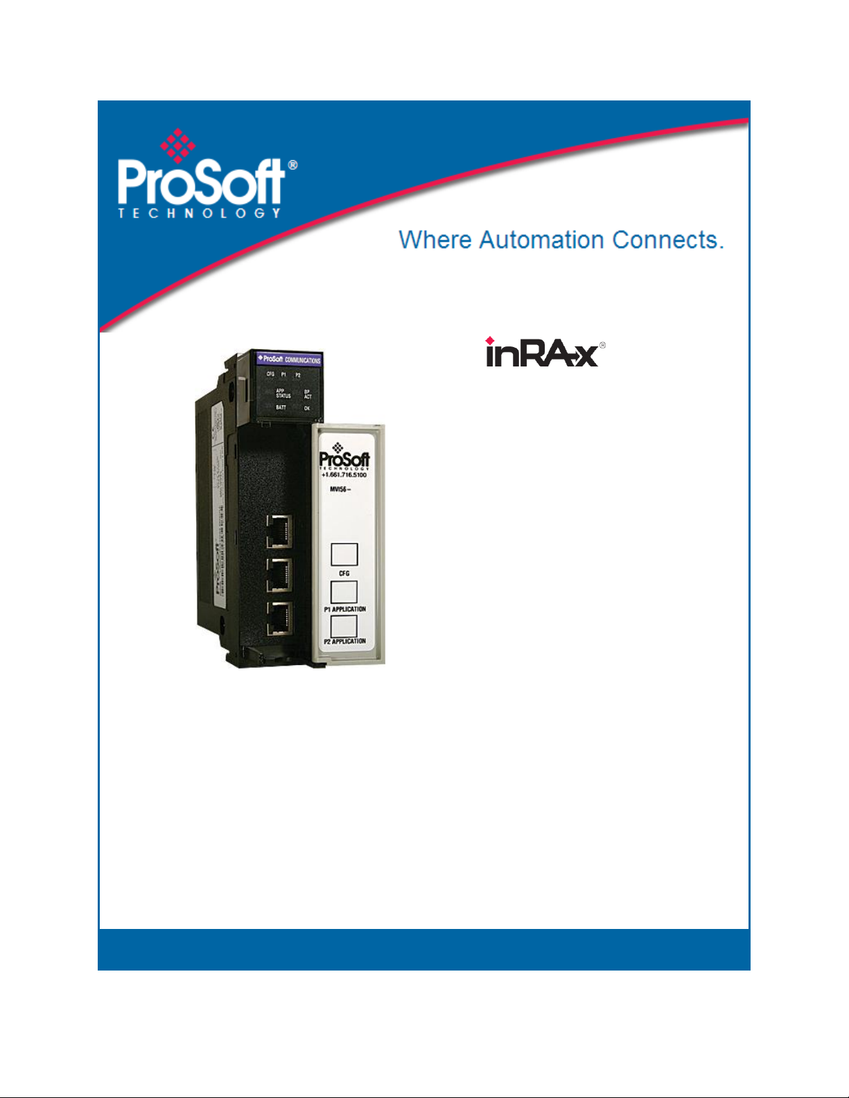
1.3 Setting Jumpers
If you use an interface other than RS-232 (default), you must change the jumper
configuration to match the interface. There are three jumpers located at the
bottom of the module.
The following illustration shows the MVI56-103M jumper configuration:
1 Set the PRT 2 (for application port 1) and PRT 3 (for application port 2)
jumpers for RS232, RS422, or RS485 to match the wiring needed for your
application. The default jumper setting for both application ports is RS-232.
2 The Setup Jumper acts as "write protection" for the module’s flash memory.
In "write protected" mode, the Setup pins are not connected, and the
module’s firmware cannot be overwritten. Do not jumper the Setup pins
together unless you are directed to do so by ProSoft Technical Support.
Page 14 of 152 ProSoft Technology, Inc.
February 22, 2013
Page 15

MVI56-103M ♦ ControlLogix Platform Start Here
IEC 60870-5-103 Master Communication Module User Manual
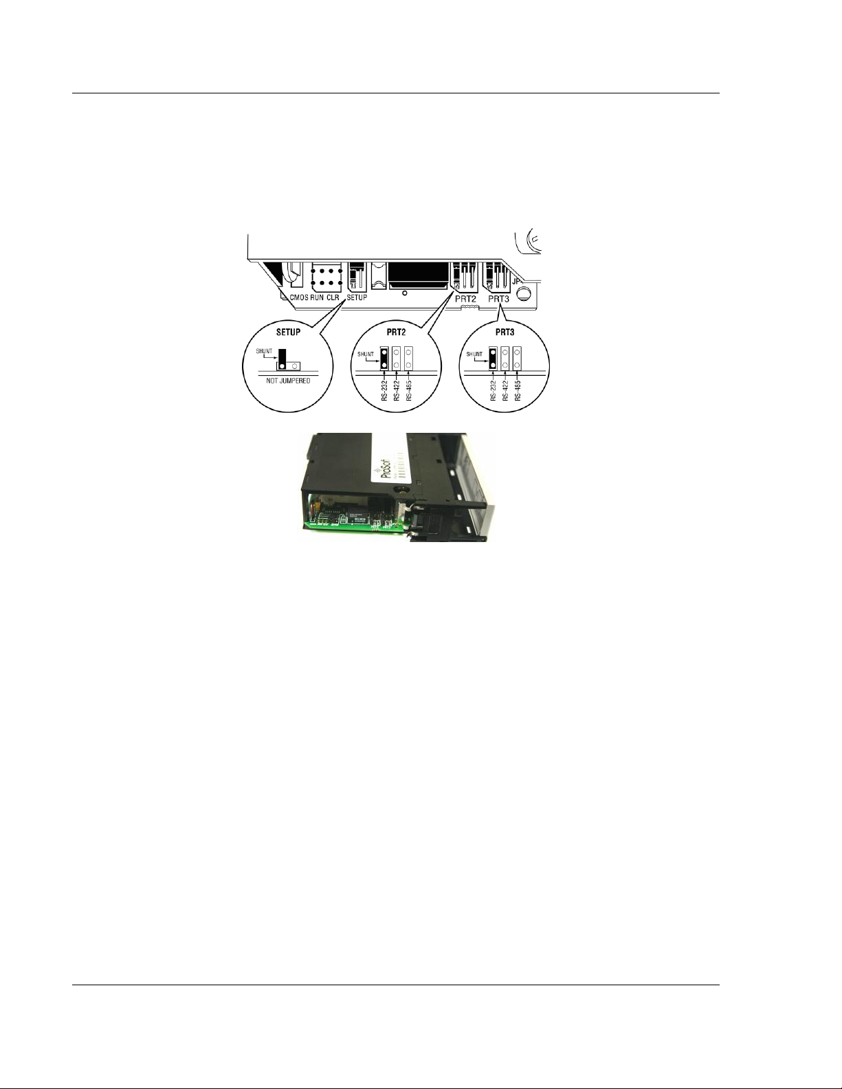
1.4 Installing the Module in the Rack
If you have not already installed and configured your ControlLogix processor and
power supply, please do so before installing the MVI56-103M module. Refer to
your Rockwell Automation product documentation for installation instructions.
Warning: You must follow all safety instructions when installing this or any other electronic
devices. Failure to follow safety procedures could result in damage to hardware or data, or even
serious injury or death to personnel. Refer to the documentation for each device you plan to
connect to verify that suitable safety procedures are in place before installing or servicing the
device.
After you have checked the placement of the jumpers, insert MVI56-103M into
the ControlLogix chassis. Use the same technique recommended by Rockwell
Automation to remove and install ControlLogix modules.
Warning: When you insert or remove the module while backplane power is on, an electrical arc
can occur. This could cause an explosion in hazardous location installations. Verify that power is
removed or the area is non-hazardous before proceeding. Repeated electrical arcing causes
excessive wear to contacts on both the module and its mating connector. Worn contacts may
create electrical resistance that can affect module operation.
1 Turn power OFF.
2 Align the module with the top and bottom guides, and slide it into the rack
until the module is firmly against the backplane connector.
ProSoft Technology, Inc. Page 15 of 152
February 22, 2013
Page 16
Start Here MVI56-103M ♦ ControlLogix Platform
User Manual IEC 60870-5-103 Master Communication Module
3 With a firm but steady push, snap the module into place.
4 Check that the holding clips on the top and bottom of the module are securely
in the locking holes of the rack.
5 Make a note of the slot location. You must identify the slot in which the
module is installed in order for the sample program to work correctly. Slot
numbers are identified on the green circuit board (backplane) of the
ControlLogix rack.
6 Turn power ON.
Note: If you insert the module improperly, the system may stop working, or may behave
unpredictably.
Page 16 of 152 ProSoft Technology, Inc.
February 22, 2013
Page 17
MVI56-103M ♦ ControlLogix Platform Start Here
IEC 60870-5-103 Master Communication Module User Manual
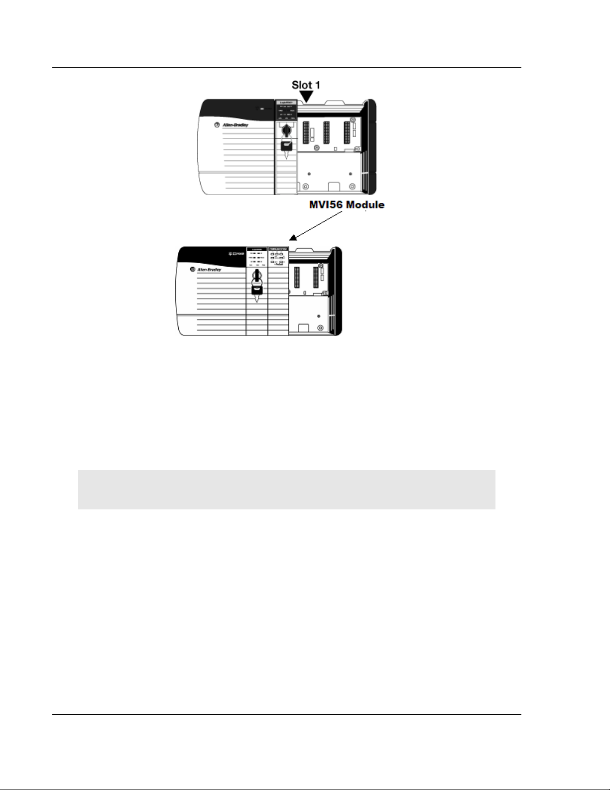
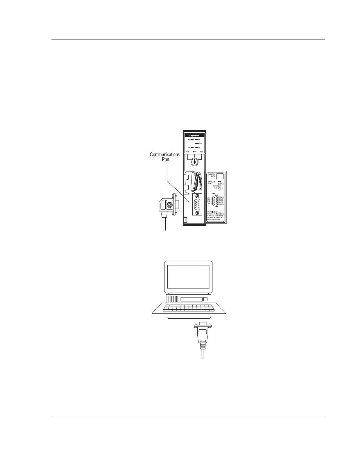
1.5 Connecting Your PC to the ControlLogix Processor
There are several ways to establish communication between your PC and the
ControlLogix processor. The following steps show how to establish
communication through the serial interface. It is not mandatory that you use the
processor's serial interface. You may access the processor through whatever
network interface is available on your system. Refer to your Rockwell Automation
documentation for information on other connection methods.
1 Connect the right-angle connector end of the cable to your controller at the
communications port.
2 Connect the straight connector end of the cable to the serial port on your
computer.
ProSoft Technology, Inc. Page 17 of 152
February 22, 2013
Page 18
Start Here MVI56-103M ♦ ControlLogix Platform
User Manual IEC 60870-5-103 Master Communication Module
1.6 Opening the Sample Ladder Logic
The sample program for your MVI56-103M module includes custom tags, data
types and ladder logic for data I/O and status monitoring. For most applications,
you can run the sample ladder program without modification, or, for advanced
applications, you can incorporate the sample program into your existing
application.
The inRAx Solutions CD provides one or more versions of the sample ladder
logic. The version number appended to the file name corresponds with the
firmware version number of your ControlLogix processor. The firmware version
and sample program version must match.
1.6.1 Configuring the RSLinx Driver for the PC COM Port
If RSLogix is unable to establish communication with the processor, follow these
steps.
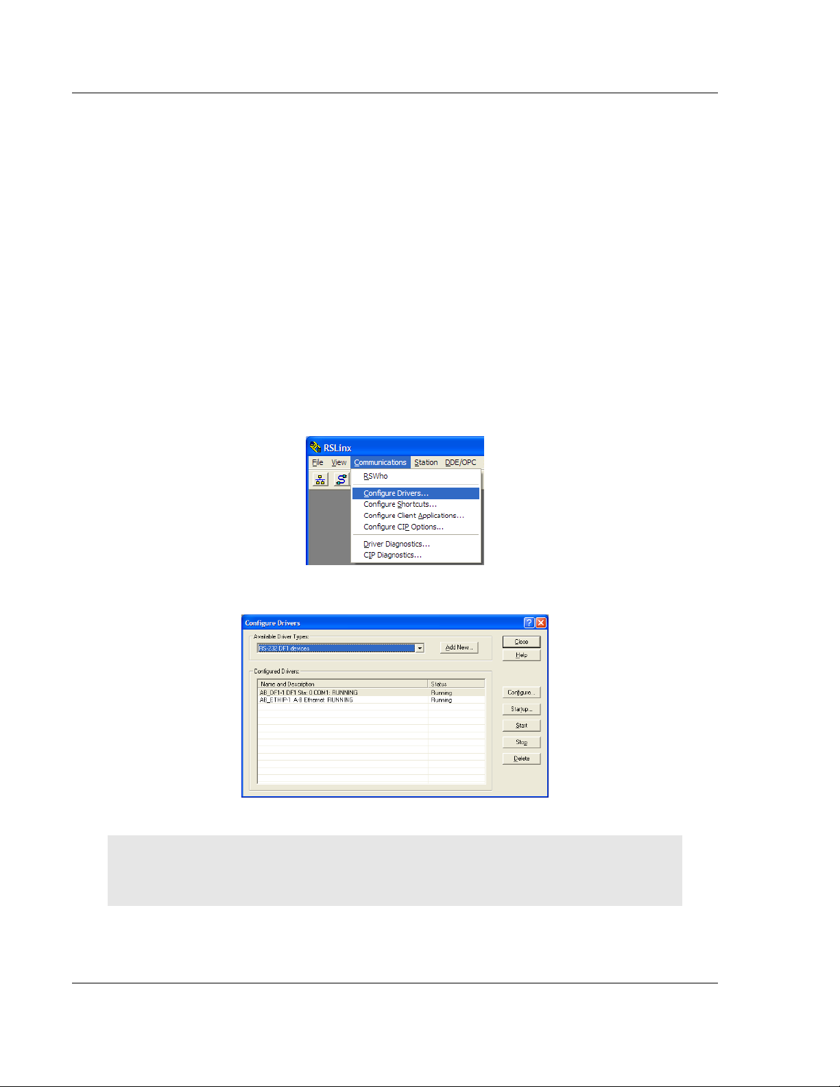
1 Open RSLinx.
2 Open the COMMUNICATIONS menu, and choose CONFIGURE DRIVERS.
This action opens the Configure Drivers dialog box.
Note: If the list of configured drivers is blank, you must first choose and configure a driver from the
Available Driver Types list. The recommended driver type to choose for serial communication with
the processor is RS-232 DF1 Devices.
Page 18 of 152 ProSoft Technology, Inc.
February 22, 2013
Page 19
MVI56-103M ♦ ControlLogix Platform Start Here
IEC 60870-5-103 Master Communication Module User Manual
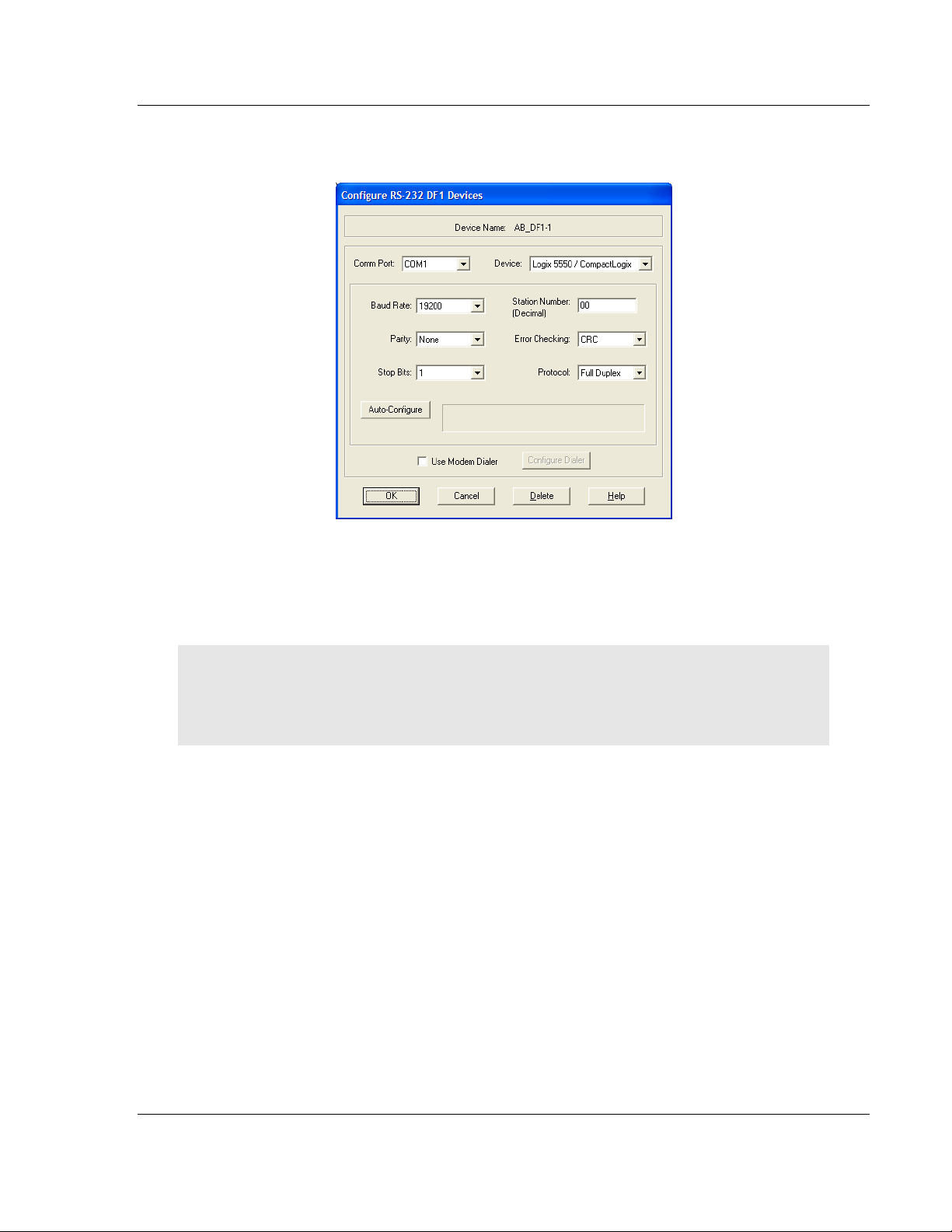
3 Click to select the driver, and then click CONFIGURE. This action opens the
Configure RS-232 DF1 Devices dialog box.
4 Click the AUTO-CONFIGURE button. RSLinx will attempt to configure your
serial port to work with the selected driver.
5 When you see the message Auto Configuration Successful, click the OK
button to dismiss the dialog box.
Note: If the auto-configuration procedure fails, verify that the cables are connected correctly
between the processor and the serial port on your computer, and then try again. If you are still
unable to auto-configure the port, refer to your RSLinx documentation for further troubleshooting
steps.
ProSoft Technology, Inc. Page 19 of 152
February 22, 2013
Page 20

Start Here MVI56-103M ♦ ControlLogix Platform
User Manual IEC 60870-5-103 Master Communication Module
1.7 Downloading the Sample Program to the Processor
Note: The key switch on the front of the ControlLogix processor must be in the REM or PROG
position.
1 If you are not already online with the processor, open the Communications
menu, and then choose DOWNLOAD. RSLogix 5000 will establish
communication with the processor. You do not have to download through the
processor's serial port, as shown here. You may download through any
available network connection.
2 When communication is established, RSLogix 5000 will open a confirmation
dialog box. Click the DOWNLOAD button to transfer the sample program to the
processor.
3 RSLogix 5000 will compile the program and transfer it to the processor. This
process may take a few minutes.
4 When the download is complete, RSLogix 5000 will open another
confirmation dialog box. If the key switch is in the REM position, click OK to
switch the processor from PROGRAM mode to RUN mode.
Note: If you receive an error message during these steps, refer to your RSLogix documentation to
interpret and correct the error.
Page 20 of 152 ProSoft Technology, Inc.
February 22, 2013
Page 21
MVI56-103M ♦ ControlLogix Platform Start Here
IEC 60870-5-103 Master Communication Module User Manual
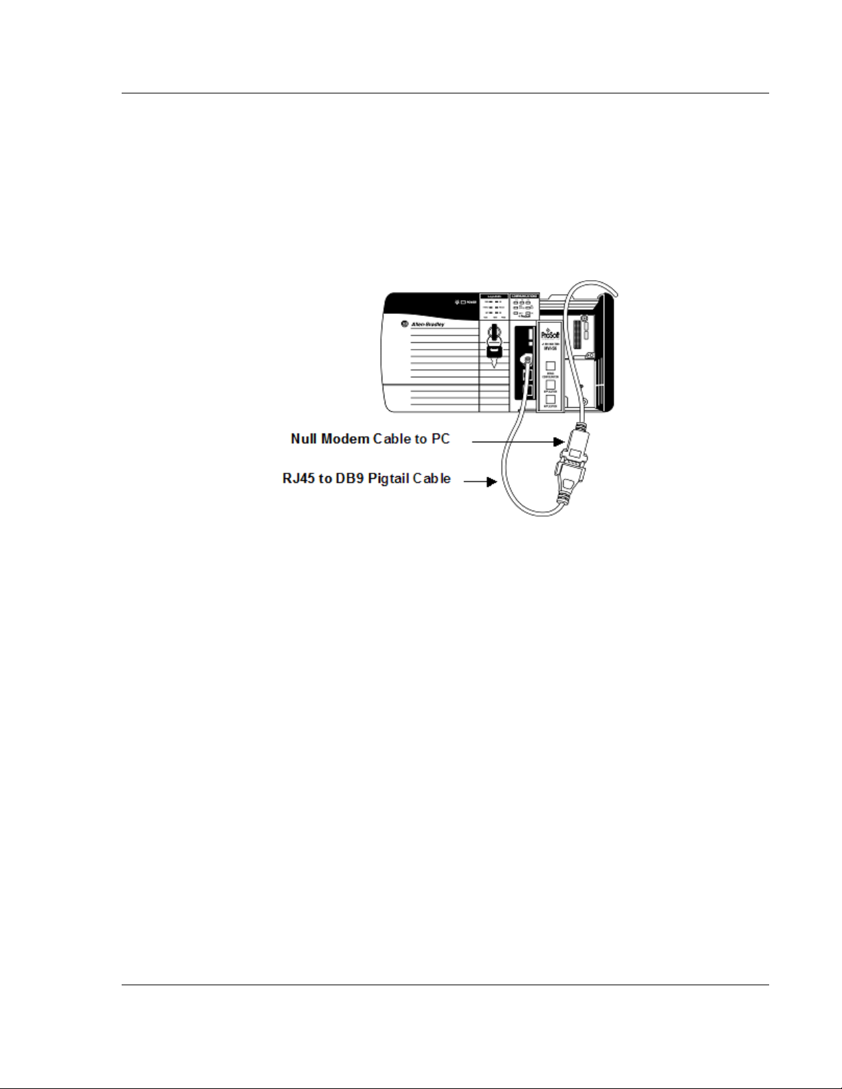
1.8 Connecting Your PC to the Module
With the module securely mounted, connect your PC to the
Configuration/Debug port using an RJ45-DB-9 Serial Adapter Cable and a Null
Modem Cable.
1 Attach both cables as shown.
2 Insert the RJ45 cable connector into the Configuration/Debug port of the
module.
3 Attach the other end to the serial port on your PC.
ProSoft Technology, Inc. Page 21 of 152
February 22, 2013
Page 22

Start Here MVI56-103M ♦ ControlLogix Platform
User Manual IEC 60870-5-103 Master Communication Module
Page 22 of 152 ProSoft Technology, Inc.
February 22, 2013
Page 23

MVI56-103M ♦ ControlLogix Platform Configuring the MVI56-103M Module
In This Chapter
Configuration File .................................................................................. 24
Quick Start ............................................................................................. 27
[Backplane Configuration] ..................................................................... 34
[IEC-870-5-103 Master] ......................................................................... 36
[IEC-870-5-103 Master Port x] ............................................................... 37
[IEC-103 Master Commands] ................................................................ 39
[IEC-103 Master Session x] ................................................................... 43
[IEC-103 Master Session x Sector y] ..................................................... 45
Uploading and Downloading the Configuration File ............................... 48
IEC 60870-5-103 Master Communication Module User Manual
2 Configuring the MVI56-103M Module
ProSoft Technology, Inc. Page 23 of 152
February 22, 2013
Page 24
Configuring the MVI56-103M Module MVI56-103M ♦ ControlLogix Platform
User Manual IEC 60870-5-103 Master Communication Module
2.1 Configuration File
The MVI56-103M module stores its configuration in a text file called
IEC103M.CFG, located in the module's flash memory. When the module starts
up, it reads the configuration file and uses the information to control how the 103
protocol interacts with the module's application port(s).
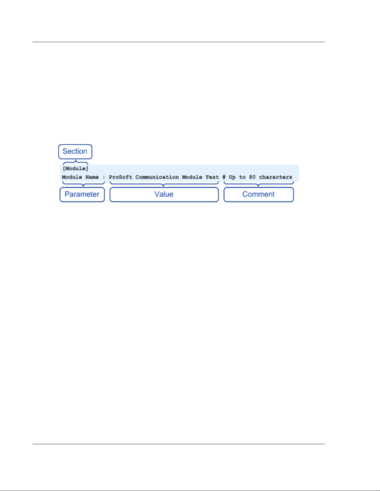
The configuration file is arranged in Sections, with a heading in [ ] characters at
the beginning of each section. Each Section contains a list of Parameters and
Values, followed by an optional Comment that explains the parameter.
The following illustration shows an example of a Section, a Parameter, a Value,
and a Comment.
The Parameter must be followed by a [:] (colon) character. The text following the
[:] is a Value.
The module ignores "comment" text following the [#] character. Use comments to
document your configuration settings.
You can get a sample configuration file for the module in the following places:
Copy the IEC103M.CFG from the module's flash memory to your PC
Copy the IEC103M.CFG from the ProSoft Solutions CD-ROM supplied with
the module
Download the IEC103M.CFG from the ProSoft Technology web site at
www.prosoft-technology.com
Page 24 of 152 ProSoft Technology, Inc.
February 22, 2013
Page 25
MVI56-103M ♦ ControlLogix Platform Configuring the MVI56-103M Module
IEC 60870-5-103 Master Communication Module User Manual
2.1.1 Editing the Configuration File
The DNPSNET_Q.CFG file consists of the following sections:
[Module]
[Backplane Configuration]
[DNP ENET Slave]
[DNP ENET IP Addresses]
[DNP Slave Binary Inputs]
[DNP Slave Analog Inputs]
[DNP Slave Float Inputs]
Important notes to consider when editing the sample configuration file:
Comments within the file are preceded by the pound (#) sign. Any text on a
line that occurs after the # character will be ignored.
Do not use tabs or other non-printing characters instead of spaces to
separate parameters (spacebar).
Parameter names must begin in the first column of a line, and may not be
preceded with a space (spacebar) or other non-printing character.
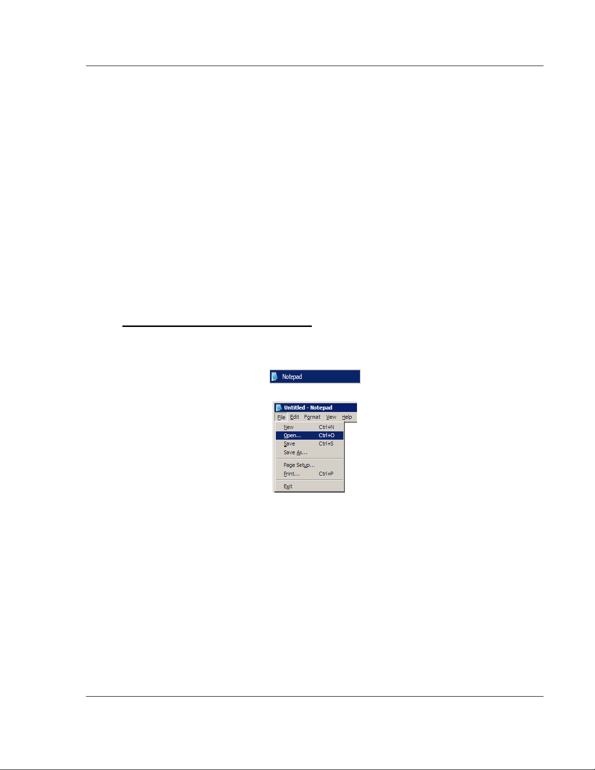
The IEC103M.CFG file is a plain ASCII text file. Use a text editor such as
Notepad.exe (included with Microsoft Windows) to open and edit the file.
To open the configuration file in Notepad
1 Click the START button, and then choose PROGRAMS
2 Expand the Programs menu, and then choose ACCESSORIES.
3 On the Accessories menu, choose NOTEPAD.
4 In Notepad, open the FILE menu, and then choose OPEN
ProSoft Technology, Inc. Page 25 of 152
February 22, 2013
Page 26
Configuring the MVI56-103M Module MVI56-103M ♦ ControlLogix Platform
User Manual IEC 60870-5-103 Master Communication Module
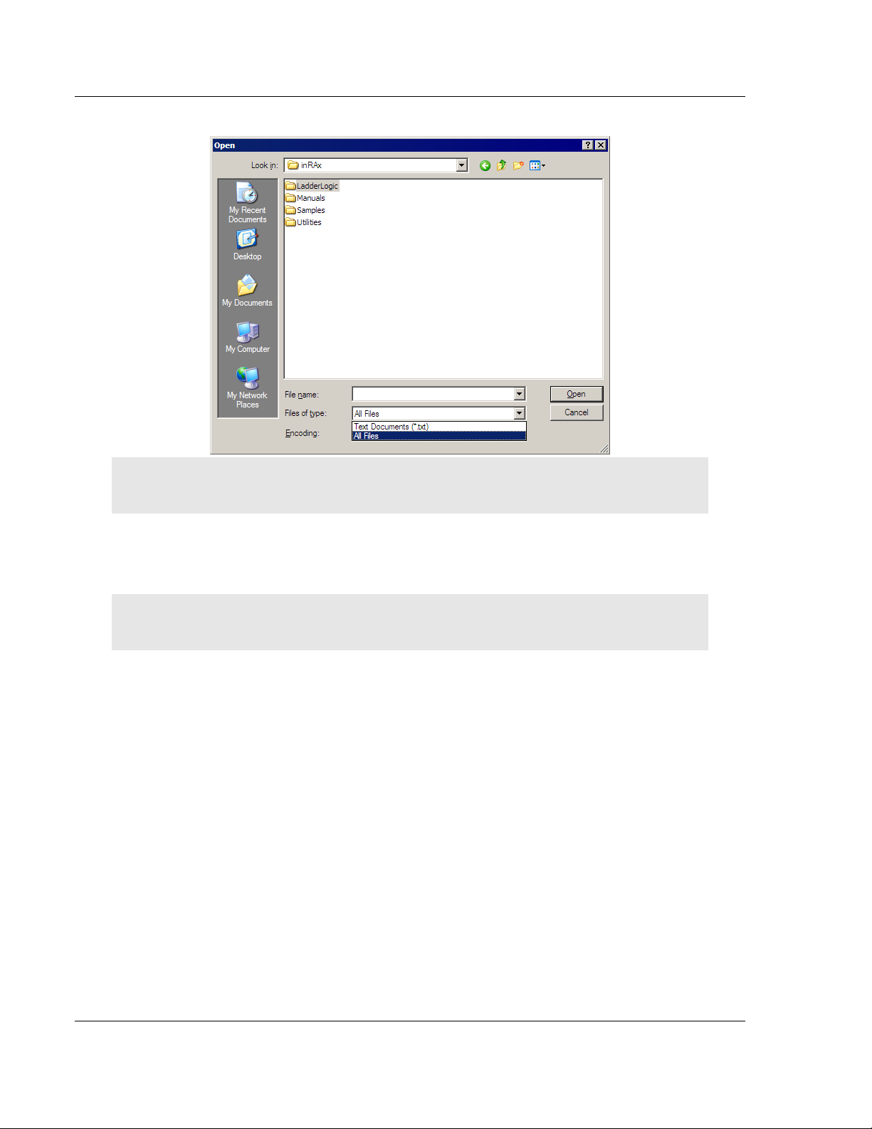
5 In the Open dialog box, select ALL FILES in the Files of Type: dropdown list.
Tip: Sample configuration files are stored under the LadderLogic folder on the ProSoft Solutions
CD-ROM.
6 Navigate to the folder containing the configuration file, and then select the file
to edit.
7 Click OPEN to open the file.
8 When you have finished editing, SAVE the file and close Notepad.
Important: Changes to the configuration file will not take effect until you download the file to the
module, and then reboot the module.
Page 26 of 152 ProSoft Technology, Inc.
February 22, 2013
Page 27

MVI56-103M ♦ ControlLogix Platform Configuring the MVI56-103M Module
IEC 60870-5-103 Master Communication Module User Manual
2.2 Quick Start
This section provides the steps required to configure the module. After you
download the sample configuration file, please perform the following steps:
Step 1: Configure the Number of Slaves (Sessions)
The IEC 60870-5-103 protocol is a Master-slave protocol where the slaves are
typically protection equipments for substations. The MVI56-103M module
supports up to 32 slaves (total) connected to its application serial ports. Each
slave has to be configured as a session. Refer to the configuration file to enter
the number of slaves that will be connected to the MVI56-103M module:
[IEC-870-5-103 Master]
Session Count: 5 #1 to 32 - maximum number of slaves on all channels
In the example above, the module will only poll sessions 0 to 4. The module
would not poll sessions 5 to 31.
In Step 3, you will configure each session as an actual slave in the network.
Step 2: Configure the Port Communication Parameters
The user should configure the port communication parameters in order to enable
data transfer between the Master and the slave(s). The port communication
parameters include baud rate, parity, RTS ON, RTS OFF and Minimum Delay.
The IEC 60870-5-103 protocol uses two baud rates: 19200 or 9600 kb/s and
even parity.
Refer to the [IEC-870-5-103 Master Port 0] section in the configuration file in
order to configure the communication parameters for the 103M port:
[IEC-870-5-103 Master Port 0]
# Communication Parameters
Baud Rate : 19200 #Baud rate for port 9600-19200
Parity : E #N=None, O=Odd, E=Even, M=Mark, S=Space
RTS On : 0 #0-65536 mSec before message
RTS Off : 1 #0-65536 mSec after message
Minimum Delay : 10 #Minimum # of mSec before response sent
Receive Timeout: 2000 #Maximum mSec from first char to last to wait
# These parameters are protocol specific
Single char ACK F0,1 or 3: Y #Single E5 resp to ACK func 0, 1 & 3 req (Y/N)
The user should also configure the jumpers located at the bottom of the module
to select the correct electrical interface mode: RS-232, RS-422 or RS-485.
Step 3: Configure the Session (Slave) Poll Parameters
According to the IEC 60870-5-103 protocol, the Master cyclically polls data from
the slaves. The data is classified into two classes; Class 1 and Class 2. Events
belong to Class 1 and analog data to Class 2. The module can request data
through Class 1 or Class 2 requests. Responses to control command and
general interrogation commands are also sent as Class 1 data.
Refer to the [IEC-103 Master Session x] section in the configuration file in order
to configure how each slave will be polled.
ProSoft Technology, Inc. Page 27 of 152
February 22, 2013
Page 28

Configuring the MVI56-103M Module MVI56-103M ♦ ControlLogix Platform
User Manual IEC 60870-5-103 Master Communication Module
Initially, the user should enter the MVI56-103M port number that will be
connected to the session (slave) using the "Communication Port" parameter.
Valid values are 0 or 1.
These parameters include the Data Link Address, which is the slave address that
identifies all protection equipment on the network. There should be a unique
number for each slave on the network. There are also certain parameters that
pertain to how the Class 1 and Class 2 polls will be used for data transfer.
You must enter the number of sectors for each session using the Sector Count
parameter. The module accepts up to 5 sectors per session.
[IEC-103 Master Session 0]
Communication Port : 0 #Index of COM port for session (0 or 1)
Sector Count : 5 #5 is max for this version of app
Data Link Address : 0 #Range is 0 to 65535 DL address of slave
Failure Delay : 3 #Min Sec to delay before poll of offline slave
#(0 to 2000 seconds)
Confirm Timeout : 20000 #0 to 4,294,967,295 msec to wait for DL confirm
Retry Count : 5 #0 to 255 retries for if no confirm
Response Timeout : 5000 #Timeout for confirm of req (0 to 4,294,967,295
msec)
C1/C2 Poll Count Pend: 6 #Class 1 or 2 polls before next slave tried (0-
65535)
Class 1 Polls : 10 #Max Class 1 polls to this session
Class 1 Pend delay : 1000 #Min mSec delay between call (0 to 4,294,967,295
msec)
Class 2 Pend delay : 1000 #Min mSec delay between call (0 to 4,294,967,295
msec)
Class 1 Poll delay : 1000 #Min mSec delay between call (0 to 4,294,967,295
msec)
Class 2 Poll delay : 1000 #Min mSec delay between call (0 to 4,294,967,295
msec)
This step should be repeated for each session to be used. For example, if the
user selected 8 sessions during Step 1, he or she should configure sessions 0 to
7:
[IEC-103 Master Session 0]
[IEC-103 Master Session 1]
[IEC-103 Master Session 2]
[IEC-103 Master Session 3]
[IEC-103 Master Session 4]
[IEC-103 Master Session 5]
[IEC-103 Master Session 6]
[IEC-103 Master Session 7]
Step 4: Sector (Data Set) Configuration
For each session (slave), you must configure one or more sectors (maximum of
5). A sector is a data set defined by the vendor. Each sector is identified by the
Common ASDU Address parameter in the [IEC-103 Master Session x Sector 0]
area in the configuration file. This area also contains some parameters that will
affect the module initialization procedure.
[IEC-103 Master Session 0 Sector 0]
Common ASDU Address : 0 #Range 0 to 255 Sector address
Page 28 of 152 ProSoft Technology, Inc.
February 22, 2013
Page 29

MVI56-103M ♦ ControlLogix Platform Configuring the MVI56-103M Module
IEC 60870-5-103 Master Communication Module User Manual
#Req init requests when session first online (not req if slave sends# EOI
sequence)
Online Time sync : Y #Send time sync message when first online
Online General Int : Y #Send general interrogation
#Req init requests when EOI (end of initialization) received from slave
EOI Time sync : Y #Send time sync message when first online
EOI General Int : Y #Send general interrogation
# Database definition for this session/sector
# Types are as follows:
#
# Monitored ASDU Types
# 1 = Time-tagged message (bit addressed with 2 bits/point)
# 2 = Time-tagged message with relative time (bit addressed with 2
bits/point)
# 3 = Measurands I (4 word values using word address using double-word
address)
# 4 = Time-tagged measurands with relative time (1 float value)
# 5 = Identification (12 characters using a byte address)
# 9 = Measurands II (9 word values using word address)
# 205 = SIEMENS Meter Data (Private Range)
#
# Point Index is the information object number in the slave unit.
# ASDU Index Description
# 1 Bit address with each point occupying 2 bits
# 2 Bit address with each point occupying 2 bits
# 3 Word address with each point occupying 4 words
# 4 Double-word address for the single float value
# 5 Byte address with each point occupying 12 bytes
# 9 Word address with each point occupying 9 words
# 205 Double-word address for each meter point
#
# Function Code Values
# Code Definition
# 128 Distance protection
# 160 Overcurrent protection
# 133 Energy
# 176 Transformer differential protection
# 192 Line Differential protection
# 255 Global function type
#
# Database Index = Database address in module
#
# ASDU Database Function Point
# Type Index Code Index
START
1 0 128 16
1 16 128 18
1 32 128 19
1 48 128 20
1 64 128 21
1 80 128 22
1 96 128 23
1 112 128 24
ProSoft Technology, Inc. Page 29 of 152
February 22, 2013
Page 30

Configuring the MVI56-103M Module MVI56-103M ♦ ControlLogix Platform
User Manual IEC 60870-5-103 Master Communication Module
1 128 128 25
1 144 128 26
205 100 133 51
205 100 133 52
END
This step should be repeated for each sector used by the application. The
module will only use the sectors configured in the previous step.
Step 5: Monitor Point Configuration (Monitor Direction)
After the slave receives a Class 1 or Class 2 request from the Master, it responds
with a message containing data. Each piece of equipment is normally configured
to respond with specific points when it is being polled with a Class 2 request.
During a Class 2 response, the slave may set a control bit (ACD) to inform the
Master that there are new events to be transmitted. Then, the Master will send a
Class 1 poll to read the events from the slave.
The IEC 60870-5-103 protocol states that the data is transferred between the
Master and slave using an ASDU (Application Service Data Unit) format. Each
format is given by:
Type Identification
Variable Structure Qualifier
Cause Of Transmission
Common Address of ASDU
Function Type
Information Number
Data…
Refer to the protection equipment specification for the following information about
each point:
Type: Type of the message
Function Type: Type of protection function
Information Number: Point Identification
This information will identify each point in the MVI56-103M configuration file. The
user has to configure the points that will be updated in the MVI56-103M database
when a Class 2 or Class 1 response containing data is sent from the slave. Refer
to [IEC-103 Master Session x Sector y] section in the configuration file in order to
configure each point:
# ASDU Database Function Point
# Type Index Code Index
START
1 0 128 16
1 16 128 17
1 32 160 18
1 48 176 19
1 64 192 20
1 80 128 21
END
Where the user should enter:
ASDU Type: ASDU type for the point
Function Type: Function type for the point
Page 30 of 152 ProSoft Technology, Inc.
February 22, 2013
Page 31

MVI56-103M ♦ ControlLogix Platform Configuring the MVI56-103M Module
ASDU Type
DB Addressing
1
Bit address with each point occupying 2 bits
2
Bit address with each point occupying 2 bits
3
Word address with each point occupying 4 words
4
Double-word address for the single float value
5
Byte address with each point occupying 12 bytes
9
Word address with each point occupying 9 words
205
SIEMENS Meter Data (Private Range)
Double-word address for each meter point
IEC 60870-5-103 Master Communication Module User Manual
Point Index: Information number for the point
Database Index: The MVI56-103M database location where the value will be
copied. Special attention should be considered since the type of addressing will
depend on the ASDU type:
For example, in order to configure the following points:
Time-tagged message point with information number 17 (teleprotection
active) and distance protection function (128). The value will be copied to bits
0 and 1 in word 1 (second word) in the module’s database.
Measurands I point with information number 144 (measurands I) and
overcurrent protection function (160). The value will be copied to word 50 in
the module’s database.
The following configuration information should be entered:
# ASDU Database Function Point
# Type Index Code Index
START
1 16 128 17
1 50 160 144
END
Every time the module responds with a Class 1 or Class 2 poll with these points,
the module will update its value to the database.
All the points configured in this section are sent from the slave to the Master. The
protocol specification refers to this data flow as the Monitor Direction.
This step should be repeated for each sector.
Step 6: Command Configuration (Control Direction)
The user might also configure the Master to send commands to slaves. The IEC
60870-5-103 protocol specification refers to this data flow as Control Direction.
The commands include general commands, interrogation requests, and time
synchronization requests. In order to configure a command, refer to the [IEC-103
Master Commands] section:
[IEC-103 Master Commands]
#
# Enable code field is as follows:
# 0 = Disabled
# 1 = Enabled with Poll Interval (seconds) utilized
# 2 = Conditional (executed when point in database changes)
#
# Database Index is the location in the module's database to use as the source
ProSoft Technology, Inc. Page 31 of 152
February 22, 2013
Page 32

Configuring the MVI56-103M Module MVI56-103M ♦ ControlLogix Platform
User Manual IEC 60870-5-103 Master Communication Module
# for the data in the command. The data type field determines
# the meaning of the index as follows:
# Type Description DB Index type
# ---- ----------------------------------- -------------------# 6 Clock synchronization NA
# 7 General interrogataion NA
# 20 General Command Bit address
#
# Poll Interval field is utilized when the Enable Code is set to 1. This field
# determines the minimum number of seconds to wait between each
# execution of the command.
#
# Session Index represents the session index in the module to associate with
the
# command. This index is set when the session is read in from
# this file. The range of values for this field is 0 to 31.
#
# Sector Index represents the sector index for the specific session. The range
# of values for this field is 0 to 4.
#
# Data type file represents the ASDU type as follows:
# 0 = Special command
# 6 = Time synchronization
# 7 = General Interrogation
# 20 = General Command
#
# Function code
# Code Definition
# 128 Distance protection
# 160 Overcurrent protection
# 176 Transformer differential protection
# 192 Line Differential protection
# 205 Meter Data for SIEMENS Devices
# 255 Global function type
#
# Point Index field is used to specify the address in the remote slave device
# of the point to interact with.
#
# Override Flag field is used for general commands to determine the value
# to be written. If the override flag is clear (0), the value
# in the database will be utilized. If the override flag is set
(1),
# the value specified in the override value field will be used.
#
# Override Value field is utilized if the override flag is set. This can be
# used to always force a control parameter to a fixed value. The
# Enable code 2 and the database value for the command can be used
# to determine when the value should be written.
#
# Enable Database Poll Session Sector Data Func Point Ovrd Ovrd
# Code Index Interval Index Index Type Code Index Flag Val
START
1 0 0 0 0 6 255 0 0 0
1 10 0 0 0 7 255 0 0 0
END
Page 32 of 152 ProSoft Technology, Inc.
February 22, 2013
Page 33

MVI56-103M ♦ ControlLogix Platform Configuring the MVI56-103M Module
IEC 60870-5-103 Master Communication Module User Manual
When sending a General Command, the user might associate the source data
with a register in the MVI56-103M database to be sent to the remote slave. The
following example will send 8 commands to the slave configured as Session
0/Sector 0. When using a General Command, the bit addressing should be used:
# Enable DB Poll Session Sector Data Func Point Ovrd Ovrd
# Code Index Interval Index Index Type Code Index Flag Val
START
1 16000 0 0 0 20 128 16 0 0
1 16016 0 0 0 20 128 17 0 0
1 16032 0 0 0 20 128 18 0 0
1 16048 0 0 0 20 128 19 0 0
1 16064 0 0 0 20 128 23 0 0
1 16080 0 0 0 20 128 24 0 0
1 16096 0 0 0 20 128 25 0 0
1 16112 0 0 0 20 128 26 0 0
END
Refer to the device specification for the Point Index (Information Number) listing
available for control direction.
The module can also send a periodic General Interrogation command in order to
initialize and refresh the event-updated points in its database. The slave keeps a
list of all data subject to General Interrogation.
Step 7: Transfer the Configuration (page 68) from the Computer to the module.
ProSoft Technology, Inc. Page 33 of 152
February 22, 2013
Page 34

Configuring the MVI56-103M Module MVI56-103M ♦ ControlLogix Platform
User Manual IEC 60870-5-103 Master Communication Module
2.3 [Backplane Configuration]
This section provides the module with a unique name, identifies the method of
failure for the communications for the module if the processor is not in RUN
mode, and describes how to initialize the module upon startup.
2.3.1 Module Name
0 to 80 characters
This parameter assigns a name to the module that can be viewed using the
configuration/debug port. Use this parameter to identify the module and the
configuration file.
2.3.2 Read Register Start
0 to 4999
The Read Register Start parameter specifies the start of the Read Data area in
module memory. Data in this area will be transferred from the module to the
processor.
Note: Total user database memory space is limited to the first 5000 registers of module memory,
addresses 0 through 4999. Therefore, the practical limit for this parameter is 4999 minus the value
entered for Read Register Count, so that the Read Data Area does not try to extend above address
4999. Read Data and Write Data Areas must be configured to occupy separate address ranges in
module memory and should not be allowed to overlap.
2.3.3 Read Register Count
0 to 5000
The Read Register Count parameter specifies the size of the Read Data area of
module memory and the number of registers to transfer from this area to the
processor, up to a maximum of 5000 words.
Note: Total Read Register Count and Write Register Count cannot exceed 5000 total registers.
Read Data and Write Data Areas must be configured to occupy separate address ranges in
module memory and should not be allowed to overlap.
Page 34 of 152 ProSoft Technology, Inc.
February 22, 2013
Page 35

MVI56-103M ♦ ControlLogix Platform Configuring the MVI56-103M Module
IEC 60870-5-103 Master Communication Module User Manual
2.3.4 Write Register Start
0 to 4999
The Write Register Start parameter specifies the start of the Write Data area in
module memory. Data in this area will be transferred in from the processor.
Note: Total user database memory space is limited to the first 5000 registers of module memory,
addresses 0 through 4999. Therefore, the practical limit for this parameter is 4999 minus the value
entered for Write Register Count, so that the Write Data Area does not try to extend above address
4999. Read Data and Write Data Areas must be configured to occupy separate address ranges in
module memory and should not be allowed to overlap.
2.3.5 Write Register Count
0 to 5000
The Write Register Count parameter specifies the size of the Write Data area of
module memory and the number of registers to transfer from the processor to
this memory area, up to a maximum value of 5000 words.
Note: Total Read Register Count and Write Register Count cannot exceed 5000 total registers.
Read Data and Write Data Areas must be configured to occupy separate address ranges in
module memory and should not be allowed to overlap.
2.3.6 Failure Flag Count
0 through 65535
This parameter specifies the number of successive transfer errors that must
occur before halting communication on the application port(s). If the parameter is
set to 0, the application port(s) will continue to operate under all conditions. If the
value is set larger than 0 (1 to 65535), communications will cease if the specified
number of failures occur.
2.3.7 Pass-Through Events
Y or N (N = Default)
This parameter specifies if event messages received on the Master ports will be
passed to the processor. If the parameter is set to N, event messages will not be
passed to the processor. If the parameter is set to Y, the module will pass all
events received to the processor using block identifier 9903.
ProSoft Technology, Inc. Page 35 of 152
February 22, 2013
Page 36

Configuring the MVI56-103M Module MVI56-103M ♦ ControlLogix Platform
User Manual IEC 60870-5-103 Master Communication Module
2.4 [IEC-870-5-103 Master]
This section establishes the total number of slaves to communicate with through
both application serial ports.
[IEC-870-5-103 Master]
Session Count : 1 #1 to 32 - maximum number of slaves on all channels
2.4.1 Session Count
1 to 32
This parameter specifies the maximum number of sessions to establish on the
module. This corresponds to the number of slaves to be interfaced with the
module. This value represents the total number of slaves on all ports.
Page 36 of 152 ProSoft Technology, Inc.
February 22, 2013
Page 37

MVI56-103M ♦ ControlLogix Platform Configuring the MVI56-103M Module
Baud Rate
Parameter Value Options
110
110
150
150
300
300
600
600
1200
12 or 1200
2400
24 or 2400
4800
48 or 4800
9600
96 or 9600
19,200
19, 192 or 19200
38,400
38, 384 or 38400
57,600
57 or 576
115,200
115 or 1152
IEC 60870-5-103 Master Communication Module User Manual
2.5 [IEC-870-5-103 Master Port x]
These section configures the communication parameters for each application
serial port on the module. The following illustration shows typical settings for a
Master port.
[IEC-870-5-103 Master Port 0]
Baud Rate : 19200
Parity : Even
RTS On : 0
RTS Off : 1
Minimum Delay : 10
Receive Timeout : 2000
Single char ACK F0,1 or 3 : Yes
2.5.1 Baud Rate
This is the baud rate to be used on the port. Enter the baud rate as a value. For
example, to select 19K baud, enter 19200.
2.5.2 Parity
N, O, E, M, or S
This parameter sets the parity to be used on the port. The values correspond to
the following settings: N=None, O=Odd, E=Even, M=Mark and S=Space.
Note: The 103M specification supports only Even Parity.
2.5.3 RTS On
0 to 65535 milliseconds
This parameter sets the number of milliseconds to delay after Ready To Send
(RTS) is asserted before data will be transmitted.
ProSoft Technology, Inc. Page 37 of 152
February 22, 2013
Page 38

Configuring the MVI56-103M Module MVI56-103M ♦ ControlLogix Platform
User Manual IEC 60870-5-103 Master Communication Module
2.5.4 RTS Off
0 to 65535 milliseconds
This parameter sets the number of milliseconds to delay after the last byte of
data is sent before the RTS modem signal will be set low.
2.5.5 Minimum Delay
1 to 60000 milliseconds
This parameter specifies the minimum number of milliseconds to delay before
sending the message (setting RTS high). This can be used when the serial
network requires time for units to turn off their transmitters.
2.5.6 Receive Timeout
1 to 65535 milliseconds
This value represents the number of milliseconds to wait on a port from the time
the first character is received until the last character in the longest message is
received. This parameter will be dependent on the baud rate. A value of 2000
should work with most applications.
2.5.7 Single char ACK F0, 1, or 3
Yes or No
This parameter specifies if the signal E5 character will be used for ACK
messages.
Page 38 of 152 ProSoft Technology, Inc.
February 22, 2013
Page 39

MVI56-103M ♦ ControlLogix Platform Configuring the MVI56-103M Module
IEC 60870-5-103 Master Communication Module User Manual
2.6 [IEC-103 Master Commands]
This section can contain up to 1000 user defined commands to be executed by
the module and sent to the controlled devices. There is no need to place Class 1
or Class 2 polls in this list for the controlled devices as the Master driver for each
port will execute these automatically when the port is idle. In order for the port to
be idle, make sure that there is idle time available, and that the commands do not
constantly utilize the ports. The command list section starts with a reserved label
START and ends with the label END. Each row in the file corresponds to an
individual command with the first character position in each row left blank (white
space).
As an alternative to using a command list, blocks with an identification code of
9901 can be used to issue commands from the ladder logic.
2.6.1 Enable Code
0 = Disabled
1 = Enabled, will execute using Poll Interval parameter (page 40) (seconds)
2 = Conditional (executed when point in database changes)
This field defines whether the command is to be executed, and under what
conditions. To disable the command, set this parameter to 0 (Disabled). You can
still execute commands through the processor, using a Special Function block.
To enable the command, set this parameter to 1.
Set the Poll Interval Time to 0 to execute the command during each scan of
the command list.
Set the Poll Interval Time to a value in seconds, to execute the command at
the specified interval (page 40).
To execute the command only if the internal data associated with the command
changes, set this parameter to 2. This value is valid only for write commands.
2.6.2 Database Index
Database Index is the location in the module's database to use as the source for
the data in the command. Refer to Data Type for specific information on
addressing (page 41).
ProSoft Technology, Inc. Page 39 of 152
February 22, 2013
Page 40

Configuring the MVI56-103M Module MVI56-103M ♦ ControlLogix Platform
User Manual IEC 60870-5-103 Master Communication Module
2.6.3 Poll Interval
This parameter specifies the minimum frequency at which the module should
execute the command when the Enable Code is set to one 1. The value is
entered in units of seconds. For example, to execute a command every 10
seconds, enter a value of 10 in the field. A value of 0 for the parameter implies
that the command should be executed every scan of the list, as quickly as
possible.
2.6.4 Session Index
0 to 31
Session Index represents the session index in the module to associate with the
command. This index is set when the session is read in from this file. The range
of values for this field is 0 to 31.
2.6.5 Sector Index
0 to 4
Sector Index represents the sector index for the specific session. There are a
maximum of five (5) sectors per session.
Page 40 of 152 ProSoft Technology, Inc.
February 22, 2013
Page 41

MVI56-103M ♦ ControlLogix Platform Configuring the MVI56-103M Module
Type ID
Description
Data Representation
1
Time-tagged messages with each data
point represented by two bits.
Dual-bit status (7.2.6.5 with 00b (0 decimal) =
not used, 01b (1 decimal) = Off, 10b (2
decimal) = On and 11b (3 decimal) = not used
2
Time-tagged messages with relative
time with each point represented by
two bits.
Dual-bit status (7.2.6.5 with 00b (0 decimal) =
not used, 01b (1 decimal) = Off, 10b (2
decimal) = On and 11b (3 decimal) = not used
3
Measurands with quality descriptor.
The lower 3 bits of the values
represented in this data type contain
status information. The upper 13 bits of
the value contained a signed, 12-bit
number. This data type will return from
1 to 4 values. The number of words
received is dependant on the
information object number and the
slave device.
Measurand with quality descriptor (7.2.6.8)
Bit 0: 0 = No overflow, 1 = Overflow
Bit 1: 0 = Valid, 1 = Invalid
Bit 2: Reserved
Bits 3 to 25: Value from -1..+1-212
4
Time-tagged measurands with relative
time with the value in the packet
represented by a single floating point
number.*
Short floating-point number stored in IEEE
STD 754 format (Fraction, Exponent, Sign)
(7.2.6.20)
5
Identification data composed of 12
characters of data. Each point in
defined of this data type should reserve
12 bytes (6-word addresses) in the
database for the data received.
Byte data as defined in 7.2.6.2. First 8 bytes
are characters 1 to 8 and last 4 bytes are
manufacture bytes either decimal (0 to 255) or
as ASCII characters.
9
Measurands with quality descriptor.
The lower 3 bits of the values
represented in this data type contain
status information. The upper 13 bits of
the value contained a signed, 12-bit
number. This data type will return from
1 to 9 values (some slaves may return
up to 16 values). The number of words
received is dependant on the
information object number and the
slave device.
Measurand with quality descriptor (7.2.6.8)
Bit 0: 0 = No overflow, 1 = Overflow
Bit 1: 0 = Valid, 1 = Invalid
Bit 2: Reserved
Bits 3 to 25: Value from -1..+1-212
20
General command to control a dualpoint object. Each command issued by
the module uses the values of two
adjacent bits in the database or an
override value specified by the user
command.
Dual-bit status (7.2.6.4 with 00b (0 decimal) =
not used, 01b (1 decimal) = Off, 10b (2
decimal) = On and 11b (3 decimal) = not used
IEC 60870-5-103 Master Communication Module User Manual
2.6.6 Data Type
When interfacing data in the processor to that of the IEC 60870-5-103 protocol, it
is important that the user understand the mapping of the data types to their
corresponding representation in the modules database. The following table lists
the data types supported by the module and their associated storage
representation:
* The words should be swapped in the ladder logic.
As shown in the previous table, all bit types are addressed as bits in the modules
database.
ProSoft Technology, Inc. Page 41 of 152
February 22, 2013
For additional details, refer to Addresing the Data Types.
Page 42

Configuring the MVI56-103M Module MVI56-103M ♦ ControlLogix Platform
Code
Definition
128
Distance protection
160
Overcurrent protection
176
Transformer differential protection
192
Line Differential protection
255
Global function type
133
Meter Data for SIEMENS Devices
1
Reset Process
2
Class 2 Polls
x
User-defined
Index Value
Description
1
Bit address with each point occupying 2 bits
2
Bit address with each point occupying 2 bits
3
Word address with each point occupying 4 words
4
Double-word address for the single float value
5
Byte address with each point occupying 12 bytes
9
Word address with each point occupying 9 words
User Manual IEC 60870-5-103 Master Communication Module
2.6.7 Function Code
Note: The last item in the Function Code dropdown list is user-defined. If you select USER DEFINED
from the dropdown list, a text box will appear below the list. You may enter any function code in
this text box that will be accepted by the destination slave.
2.6.8 Point Index
The Point Index specifies the point address to be accessed in the remote slave
device.
2.6.9 Override Flag
0 or 1
Override Flag field is used for general commands to determine the value to be
written. If the override flag is clear (0), the value in the database will be utilized. If
the override flag is set (1), the value specified in the override value field will be
used.
2.6.10 Override Value
If the Override Flag is set to "Yes", you can use this setting to always force a
control parameter to a fixed value. Use Enable code CONDITIONAL and the
database value for the command to determine when the value should be written.
Page 42 of 152 ProSoft Technology, Inc.
February 22, 2013
Page 43

MVI56-103M ♦ ControlLogix Platform Configuring the MVI56-103M Module
IEC 60870-5-103 Master Communication Module User Manual
2.7 [IEC-103 Master Session x]
This section defines Session y, which runs on Port x. The Session Count
parameter in the [IEC-870-5-103 Master] section of the configuration (page 36)
determines the number of sessions (controlled devices) for this port.
The sessions are referenced by a zero-based index value. For example, if the
module is configured for four sessions, the configuration file should contain
sections for Sessions 0 to 3 (that is, [IEC-103 Master Session 0] to [IEC-103
Master Session 3]).
The parameters in [IEC-103 Master Session y] define the characteristics of the
specific controlled device to interface.
2.7.1 Communication Port
0 or 1
This parameter sets the port to which the controlled device is connected. On this
module, values of 0 and 1 are permitted.
2.7.2 Sector Count
1 to 5
This parameter sets the number of sectors contained in this controlled device.
The range of values is from 1 to 5. A sector section is required for each sector in
a session to define its database and settings.
2.7.3 Data Link Address
0 to 65535
This parameter defines the Data Link Address for the device emulated on the
module. This address identifies the module on the network along with the
common address of ASDU.
2.7.4 Failure Delay
0 to 2000 seconds
This parameter sets the minimum number of seconds to delay before polling this
session when it is not online. This parameter is only used in unbalanced mode.
2.7.5 Confirm Timeout
0 to 4,294,967,295 (two raised to the power of 32, minus one) milliseconds
This parameter sets the number of milliseconds to wait for a confirm response
from the controlled device.
ProSoft Technology, Inc. Page 43 of 152
February 22, 2013
Page 44

Configuring the MVI56-103M Module MVI56-103M ♦ ControlLogix Platform
User Manual IEC 60870-5-103 Master Communication Module
2.7.6 Retry Count
0 to 255
In balanced mode, this parameter specifies the number of retries (0 to 255) if a
response is not received. In unbalanced mode, this parameter is ignored.
2.7.7 C1/C2 Poll Count Pend
0 to 65535
This parameter sets the maximum number of Class 1 and Class 2 polls
performed on this session before trying the next session. This parameter
prevents a session from monopolizing the communication port.
2.7.8 Class 1 Polls
0 to 100
This parameter sets the maximum number of Class 1 polls performed on this
session before switching to another session. This parameter prevents a session
from monopolizing the communication port.
2.7.9 Class 1 Pend Delay
0 to 4,294,967,295 (two raised to the power of 32, minus one) milliseconds
This parameter sets the minimum number of milliseconds to delay between Class
1 polls for pending data.
2.7.10 Class 2 Pend Delay
0 to 4,294,967,295 (two raised to the power of 32, minus one) milliseconds
This parameter sets the minimum number of milliseconds to delay between Class
2 polls for pending data.
2.7.11 Class 1 Poll Delay
0 to 4,294,967,295 (two raised to the power of 32, minus one) milliseconds
This parameter sets the minimum number of milliseconds to delay between each
Class 1 poll.
2.7.12 Class 2 Poll Delay
0 to 4,294,967,295 (two raised to the power of 32, minus one) milliseconds
This parameter sets the minimum number of milliseconds to delay between each
Class 2 poll.
Page 44 of 152 ProSoft Technology, Inc.
February 22, 2013
Page 45

MVI56-103M ♦ ControlLogix Platform Configuring the MVI56-103M Module
IEC 60870-5-103 Master Communication Module User Manual
2.8 [IEC-103 Master Session x Sector y]
This section defines Sector z, which belongs to Session y. The Sector Count
parameter (page 43) in the [IEC-870-5-103 Master Session y] section specifies
the number of sectors for the session.
Each sector has a corresponding [IEC-103 Master Session y Sector z] section,
where y represents the session index and z represents the sector index.
The sectors are referenced by a zero-based index value. For example, if Session
0 is configured for four sectors, the configuration file should contain sections for
Sectors 0 to 3 (that is, [IEC-103 Master Session 0 Sector 0] to [IEC-103 Master
Session 0 Sector 3]).
2.8.1 Common ASDU Address
0 to 255
This parameter sets the common ASDU address to association with this sector of
the specified session. This parameter is usually set the same as the Data Link
Address when only one sector is used.
2.8.2 Online Time Sync
Yes or No
This parameter specifies if the sector in the controlled device will be sent a time
synchronization command when the unit is first recognized as being online. This
should only be used for devices that do not send an EOI message after
initializing.
2.8.3 Online General Int
Yes or No
This parameter specifies if the sector in the controlled device will be sent a
general interrogation command when the unit is first recognized as being online.
This should only be used for devices that do not send an EOI message after
initializing.
2.8.4 EOI Time Sync
Yes or No
This parameter specifies if the sector in the controlled device will be sent a time
synchronization command after this module received an EOI message from the
controlled unit.
2.8.5 EOI General Int
Yes or No
This parameter specifies if the sector in the controlled device will be sent a
general interrogation command after this module received an EOI message from
the controlled unit.
ProSoft Technology, Inc. Page 45 of 152
February 22, 2013
Page 46

Configuring the MVI56-103M Module MVI56-103M ♦ ControlLogix Platform
Type
Description
DB Index type
6
Clock synchronization
NA 7 General interrogation
NA
20
General Command
Bit address
Code
Definition
128
Distance protection
160
Overcurrent protection
176
Transformer differential protection
192
Line Differential protection
133
For SIEMENS ASDU type 205
255
Global function type
x
User-defined
User Manual IEC 60870-5-103 Master Communication Module
2.8.6 ASDU Type
This field contains the ASDU type code for the data contained in the message.
1 = Time-tagged message (bit addressed with 2 bits/point)
2 = Time-tagged message with relative time (bit addressed with 2 bits/point)
3 = Measurands I (4 word values using word address using double-word
address)
4 = Time-tagged measurands with relative time (1 float value)
5 = Identification (12 characters using a byte address)
9 = Measurands II (9 word values using word address)
205 = Siemens meter data
2.8.7 Database Index
Database Index is the location in the module's database to use as the source for
the data in the command. Refer to Data Type for specific information on
addressing (page 41).
The data type field determines the meaning of the database index as follows:
2.8.8 Function Code
Note: The last item in the Function Code dropdown list is user-defined. If you select USER DEFINED
from the dropdown list, a text box will appear below the list. You may enter any function code in
this text box that will be accepted by the destination slave.
Page 46 of 152 ProSoft Technology, Inc.
February 22, 2013
Page 47

MVI56-103M ♦ ControlLogix Platform Configuring the MVI56-103M Module
Index Value
Description
1
Bit address with each point occupying 2 bits
2
Bit address with each point occupying 2 bits
3
Word address with each point occupying 4 words
4
Double-word address for the single float value
5
Byte address with each point occupying 12 bytes
9
Word address with each point occupying 9 words
IEC 60870-5-103 Master Communication Module User Manual
2.8.9 Point Index
Point Index specifies the address in the remote slave device of the point to
interact with.
ProSoft Technology, Inc. Page 47 of 152
February 22, 2013
Page 48

Configuring the MVI56-103M Module MVI56-103M ♦ ControlLogix Platform
DOS
ProComm, as well as several other terminal emulation programs
Windows 3.1
Terminal
Windows 95/98
HyperTerminal
Windows NT/2000/XP
HyperTerminal
User Manual IEC 60870-5-103 Master Communication Module
2.9 Uploading and Downloading the Configuration File
ProSoft modules are shipped with a pre-loaded configuration file. In order to edit
this file, you may transfer the file from the module to your PC or locate and load
the file from the distribution CD-ROM supplied with the module. After editing, you
must transfer the file back to the module for your changes to take effect.
This section describes these procedures.
Important: The illustrations of configuration/debug menus in this section are intended as a general
guide and may not exactly match the configuration/debug menus in your own module. For specific
information about the configuration/debug menus in your module, refer to The Configuration/Debug
Menu (page 68).
2.9.1 Required Hardware
You can connect directly from your computer’s serial port to the serial port on the
module to view configuration information, perform maintenance, and send or
receive configuration files.
ProSoft Technology recommends the following minimum hardware to connect
your computer to the module:
80486 based processor (Pentium preferred)
1 megabyte of memory
At least one UART hardware-based serial communications port available.
USB-based virtual UART systems (USB to serial port adapters) often do not
function reliably, especially during binary file transfers, such as when
uploading/downloading configuration files or module firmware upgrades.
2.9.2 Required Software
In order to send and receive data over the serial port (COM port) on your
computer to the module, you must use a communication program (terminal
emulator).
A simple communication program called HyperTerminal is pre-installed with
recent versions of Microsoft Windows operating systems. If you are connecting
from a machine running DOS, you must obtain and install a compatible
communication program. The following table lists communication programs that
have been tested by ProSoft Technology.
The module uses the Ymodem file transfer protocol to send and receive
configuration files from your module. If you use a communication program that is
not on the list above, please be sure that it supports Ymodem file transfers.
Page 48 of 152 ProSoft Technology, Inc.
February 22, 2013
Page 49

MVI56-103M ♦ ControlLogix Platform Configuring the MVI56-103M Module
IEC 60870-5-103 Master Communication Module User Manual
2.9.3 Transferring the Configuration File to Your PC
1 Connect your PC to the Configuration/Debug port of the module using a
terminal program such as HyperTerminal. Press [?] to display the main
menu.
2 From the Transfer menu in HyperTerminal, select Receive File.
3 In the Receive File dialog box, browse to the location on your PC where the
configuration file should be stored, and select Ymodem as the receiving
protocol.
When you have completed your selections, click Close.
ProSoft Technology, Inc. Page 49 of 152
February 22, 2013
Page 50

Configuring the MVI56-103M Module MVI56-103M ♦ ControlLogix Platform
User Manual IEC 60870-5-103 Master Communication Module
4 Press [S] (Send Module Configuration), and then press [Y] to confirm the
transfer.
The file transfer will then begin automatically, using the protocol and location
you specified in Step 3.
When the configuration file has been transferred to your PC, the dialog box
will indicate that the transfer is complete.
The configuration file is now on your PC at the location you specified.
5 You can now open and edit the file in a text editor such as Windows Notepad.
(page 25) When you have finished editing the file, save it and close Notepad.
Page 50 of 152 ProSoft Technology, Inc.
February 22, 2013
Page 51

MVI56-103M ♦ ControlLogix Platform Configuring the MVI56-103M Module
IEC 60870-5-103 Master Communication Module User Manual
2.9.4 Transferring the Configuration File to the Module
Perform the following steps to transfer a configuration file from your PC to the
module.
1 Connect your PC to the Configuration/Debug port of the module using a
terminal program such as HyperTerminal. Press [?] to display the main
menu.
2 Press [R] (Receive Module Configuration). The message "Press Y key to
confirm configuration receive!" is displayed at the bottom of the screen.
3 Press [Y]. The screen now indicates that the PC is ready to send.
ProSoft Technology, Inc. Page 51 of 152
February 22, 2013
Page 52

Configuring the MVI56-103M Module MVI56-103M ♦ ControlLogix Platform
User Manual IEC 60870-5-103 Master Communication Module
4 From the Transfer menu in HyperTerminal, select Send File.
The Send File dialog appears.
5 Use the Browse button to locate the configuration file your computer.
Note: This procedure assumes that you are transferring a newly edited configuration file from your
PC to the module. However, the factory default configuration file is also available on the ProSoft
CD, as well as from the ProSoft Technology web site.
6 Select Zmodem as the protocol.
Page 52 of 152 ProSoft Technology, Inc.
February 22, 2013
Page 53

MVI56-103M ♦ ControlLogix Platform Configuring the MVI56-103M Module
IEC 60870-5-103 Master Communication Module User Manual
7 Click the Send button. This action opens the Zmodem File Send dialog box.
When the transfer is complete, the screen indicates that the module has
reloaded program values and displays information about the module.
8 Your module now contains the new configuration. To ensure your
configuration changes take effect, please reboot the module by using the
Warm Boot options on the Diagnostics Main Menu or by using the WarmBoot
or ColdBoot options from ladder logic.
ProSoft Technology, Inc. Page 53 of 152
February 22, 2013
Page 54

Configuring the MVI56-103M Module MVI56-103M ♦ ControlLogix Platform
User Manual IEC 60870-5-103 Master Communication Module
Page 54 of 152 ProSoft Technology, Inc.
February 22, 2013
Page 55

MVI56-103M ♦ ControlLogix Platform Ladder Logic
In This Chapter
Module Data .......................................................................................... 56
Command Control Data Object ............................................................. 60
Event Message Data Object .................................................................. 62
Adding the Module to an Existing Project .............................................. 63
IEC 60870-5-103 Master Communication Module User Manual
3 Ladder Logic
Ladder logic is required for application of the MVI56-103M module. Tasks that
must be handled by the ladder logic are module data transfer, special block
handling, and status data receipt. Additionally, a power-up handler may be
needed to handle the initialization of the module’s data and to clear any
processor fault conditions.
The sample ladder logic, on the ProSoft Solutions CD-ROM, is extensively
commented, to provide information on the purpose and function of each rung. For
most applications, the sample ladder will work without modification.
ProSoft Technology, Inc. Page 55 of 152
February 22, 2013
Page 56

Ladder Logic MVI56-103M ♦ ControlLogix Platform
Name
Data Type
Description
GenStat
I103MStat
BP
I103MBackplane
User Manual IEC 60870-5-103 Master Communication Module
3.1 Module Data
This section describes the controller tags that are defined in the example logic to
interface with the module. The user can extend these tags to meet the
specifications required for their application.
3.1.1 Module Status Data and Variables (I103MModuleDef)
All status and variable data related to the MVI56-103M is stored in a user-defined
data type. An instance of the data type is required before the module can be
used. This is done by declaring a variable of the data type in the Controller Tags
Edit Tags dialog box. The following table describes the structure of the object.
This object contains objects that define variables for the module and status data
related to the module. Each of these object types is discussed in the following
topics of the document.
Page 56 of 152 ProSoft Technology, Inc.
February 22, 2013
Page 57

MVI56-103M ♦ ControlLogix Platform Ladder Logic
Name
Data Type
Description
Scan_Cnt
INT
Product_Name
SINT[4]
Rev_Level
SINT[4]
Op_Sys
SINT[4]
Run_Number
SINT[4]
Blk_Rd_Count
INT Blk_Wr_Count
INT
Blk_Parse_Cnt
INT Blk_Err
INT
Evnt_Cnt
INT Evnt_Overflow
INT
SesCnt
INT CurCmd
INT
CmdBusy
INT
CmdMax
INT CmdDelay
INT CmdQueue
INT
CmdQCnt
INT
Online
DINT
ChStat
I103MCHStat[2]
IEC 60870-5-103 Master Communication Module User Manual
Status Object (I103MStat)
This object stores the status data of the module. The I103MStat object shown
below is updated each time a read block is received by the processor. Use this
data to monitor the state of the module at a "real-time rate".
Within the I103MStat objects are objects containing the status information for
each application port (I103MCHStat). Refer to Channel Status Object (page 58)
for a complete listing of the data stored in this object.
ProSoft Technology, Inc. Page 57 of 152
February 22, 2013
Page 58

Ladder Logic MVI56-103M ♦ ControlLogix Platform
Data Type
Description
State
State machine value
CmdReq
Number of command requests
CmdResp
Number of command responses
CmdErr
Number of command errors
Req
Number of request messages
Resp
Number of responses
ErrSent
Number of errors sent
ErrRec
Number of errors received
CfgErr
Configuration Error Word for channel
CurErr
Current error code for channel
LastErr
Last error for channel
Bit
Code
Description
0
0x0001
Invalid baud rate selected
1
0x0002
Invalid parity selected
2
0x0004
Received timeout set to 0
3
0x0008
Invalid Port selected for a session
4
0x0010
Invalid sector count for session
5
0x0020
Could not allocate memory for sector of a session.
6
0x0040
7
0x0080
Invalid failure delay or confirm timeout for session.
8
0x0100
9
0x0200
10
0x0400
11
0x0800
12
0x1000
13
0x2000
14
0x4000
15
0x8000
User Manual IEC 60870-5-103 Master Communication Module
Channel Status Object (I103MCHStat)
The I103MCHStat object holds the status data related to a single IEC 60870-5103 Master port. The following table describes the structure of the object.
This information is passed to the controller from the module with each normal
read block image.
Configuration/Error Status Flags (CfgErr)
The CfgErr word member of the I103MCHStat reports configuration errors for the
respective server. If the module is not functioning as expected, inspect the value
presented in this object. If a configuration error exists, the associated bit will be
set. A value of zero for the bit indicates the configuration value is valid. This does
not guarantee that the module is configured correctly for your application. The
bits used by this member are shown in the following table.
Page 58 of 152 ProSoft Technology, Inc.
February 22, 2013
Page 59

MVI56-103M ♦ ControlLogix Platform Ladder Logic
Name
Data Type
Description
LastRead
INT
LastWrite
INT BlockIndex
INT
IEC 60870-5-103 Master Communication Module User Manual
Backplane Object (I103MBackplane)
The I103MBackplane object stores all the variables required for the data transfer
operation between the module and the controller. The LastRead data member is
used as the handshaking word to indicate the arrival of new data from the
module. The following table describes the structure of the object.
The other members of the object are utilized in the ladder logic to assist in the
data transfer operation.
3.1.2 Data Object
Data for the module is stored in two controller tags for the example ladder logic.
The Read Data (data transferred from the module to the processor) is stored in
the controller tag array, I103ReadData[ ]. The Write Data (data transferred from
the processor to the module) is stored in the controller tag array, I103WriteData[
]. Separate tags can be constructed for each data type utilized by the controlled
devices and for each device.
ProSoft Technology, Inc. Page 59 of 152
February 22, 2013
Page 60

Ladder Logic MVI56-103M ♦ ControlLogix Platform
Name
Data Type
Description
DBIndex
INT Session
INT
Sector
INT DataType
INT
Func
INT Pnt
INT
OvrFlg
INT OvrVal
INT
Res1
INT Res2
INT
User Manual IEC 60870-5-103 Master Communication Module
3.2 Command Control Data Object
In order to support the command control option of the module, a controller tag
array, I103Cmds[ ] and two Boolean tags, I103CmdExecute1 and
I103CmdExecute2. The bits in the I103CmdExecute tags trigger ladder logic that
moves the command parameters contained in the I103Cmds[ ] array out to the
module for execution on the networks. The I103Cmds[ ] are created using the
User-defined Data Type, I103Cmd, that contains the data necessary to build a
user command. The following table describes the structure of this object.
Refer to the Command List section of this document for the definition of each of
the parameters. This option permits execution of user-generated commands from
the ladder logic directly to controlled devices. This feature is especially important
in generating general commands, ASDU 20 object requests.
Example ladder logic to use this feature is shown in the following rung:
Page 60 of 152 ProSoft Technology, Inc.
February 22, 2013
Page 61

MVI56-103M ♦ ControlLogix Platform Ladder Logic
IEC 60870-5-103 Master Communication Module User Manual
When the trigger bit (I103CmdExecute1) is set, the module will build a block
9901 with the command contained in the first command of the I103Cmds[ ]. The
module receives this block and builds and sends the command to the specified
control device. The data for the command element in the I103Cmds array is
shown in the following illustration.
The following rung displays ladder logic to build a 9902 block to place commands
2 and 3 of the user command list configured in the module's command queue:
When the trigger bit (I103CmdExecute2) is set, the module will build the block
9902 in the output image. The module will receive the new block and place the
commands into the command queue for execution.
ProSoft Technology, Inc. Page 61 of 152
February 22, 2013
Page 62

Ladder Logic MVI56-103M ♦ ControlLogix Platform
Name
Data Type
Description
SessSect
INT
ASDU
INT FuncPnt
INT
FaultNum
INT mSec
INT
HrMin
INT VDst
INT
RelTime
INT val
DINT
User Manual IEC 60870-5-103 Master Communication Module
3.3 Event Message Data Object
The module can be configured to pass event messages received from the
controlled devices to the processor. The module sends this information to the
processor in read blocks with identification codes of 9903. The example ladder
logic has a data structure that conforms to the data structure sent for each
element by the module. The following table describes the structure of this object.
The example ladder logic defines a 20-element array of the I103Mevent objects
to hold the data received in a single 9903 block. Ladder logic to handle a 9903
block is shown in the following figure:
This simple logic does not use the message count parameter in the block and will
not work for most applications. It is only provided as an example to display how
to move the 9903 data to a user controller tag. If the message pass-through
feature is utilized, more logic is required to store the messages received. This
feature is most commonly utilized to pass events from the controlled device to an
event logger connected to the processor.
Page 62 of 152 ProSoft Technology, Inc.
February 22, 2013
Page 63

MVI56-103M ♦ ControlLogix Platform Ladder Logic
IEC 60870-5-103 Master Communication Module User Manual
3.4 Adding the Module to an Existing Project
1 Select the I/O Configuration folder in the Controller Organization window of
RSLogix 5000, and then click the right mouse button to open a shortcut
menu. On the shortcut menu, choose NEW MODULE.
This action opens the Select Module dialog box:
2 Select the 1756-MODULE (GENERIC 1756 MODULE) from the list and click OK.
This action opens the New Module dialog box.
3 Enter the Name, Description and Slot options for your application. You must
select the Comm Format as DATA - INT in the dialog box, otherwise the
module will not communicate. Click OK to continue.
ProSoft Technology, Inc. Page 63 of 152
February 22, 2013
Page 64

Ladder Logic MVI56-103M ♦ ControlLogix Platform
Parameter
Value
Name
Enter a module identification string. Example: 103M_2
Description
Enter a description for the module. Example: IEC 60870-
5-103 MASTER COMMUNICATION MODULE
Comm Format
Select DATA-INT.
Slot
Enter the slot number in the rack where the MVI56-103M
module is located.
Input Assembly Instance
1
Input Size
250
Output Assembly Instance
2
Output Size
248
Configuration Assembly Instance
4
Configuration Size
0
User Manual IEC 60870-5-103 Master Communication Module
4 Select the Requested Packet Interval value for scanning the I/O on the
module. This value represents the minimum frequency that the module will
handle scheduled events. This value should not be set to less than 1
millisecond. The default value is 5 milliseconds. Values between 1 and 10
milliseconds should work with most applications.
Page 64 of 152 ProSoft Technology, Inc.
February 22, 2013
Page 65

MVI56-103M ♦ ControlLogix Platform Ladder Logic
IEC 60870-5-103 Master Communication Module User Manual
5 Save the module. Click OK to dismiss the dialog box. The Controller
Organization window now displays the module's presence.
6 Copy the User-Defined Data Types from the sample program into your
existing RSLogix 5000 project.
7 Copy the Controller Tags from the sample program into your project.
8 Copy the Ladder Rungs from the sample program into your project.
ProSoft Technology, Inc. Page 65 of 152
February 22, 2013
Page 66

Ladder Logic MVI56-103M ♦ ControlLogix Platform
User Manual IEC 60870-5-103 Master Communication Module
Page 66 of 152 ProSoft Technology, Inc.
February 22, 2013
Page 67

MVI56-103M ♦ ControlLogix Platform Diagnostics and Troubleshooting
In This Chapter
Reading Status Data from the Module .................................................. 68
LED Status Indicators ............................................................................ 84
Clearing a Fault Condition ..................................................................... 85
Troubleshooting ..................................................................................... 86
Frequently Asked Questions ................................................................. 87
IEC 60870-5-103 Master Communication Module User Manual
4 Diagnostics and Troubleshooting
The module provides information on diagnostics and troubleshooting in the
following forms:
LED status indicators on the front of the module provide general information
on the module's status.
Status data contained in the module can be viewed through the
Configuration/Debug port, using the troubleshooting and diagnostic
capabilities of ProSoft Configuration Builder (PCB).
Status data values can be transferred from the module to processor memory
and can be monitored there manually or by customer-created logic.
ProSoft Technology, Inc. Page 67 of 152
February 22, 2013
Page 68

Diagnostics and Troubleshooting MVI56-103M ♦ ControlLogix Platform
User Manual IEC 60870-5-103 Master Communication Module
4.1 Reading Status Data from the Module
The MVI56-103M module returns a status data set to the ControlLogix processor
in each read block. This data is transferred to the ControlLogix processor
continuously with each read block.
The Configuration/Debug port provides the following functionality:
Full view of the module’s configuration data
View of the module’s status data
Version Information
Control over the module (warm boot and cold boot)
Facility to upload and download the module’s configuration file
4.1.1 The Configuration/Debug Menu
The Configuration and Debug menu for this module is arranged as a tree
structure, with the Main Menu at the top of the tree, and one or more sub-menus
for each menu command. The first menu you see when you connect to the
module is the Main menu.
Because this is a text-based menu system, you enter commands by typing the
command letter from your computer keyboard in Prosoft Configuration Builder
(PCB). The module does not respond to mouse movements or clicks. The
command executes as soon as you press the command letter — you do not need
to press [Enter]. When you type a command letter, a new screen will be
displayed in your terminal application.
Navigation
All of the submenus for this module contain commands to redisplay the menu or
return to the previous menu. You can always return from a submenu to the next
higher menu by pressing [M] on your keyboard.
The organization of the menu structure is represented in simplified form in the
following illustration:
The remainder of this section shows the menus available for this module, and
briefly discusses the commands available to you.
Keystrokes
The keyboard commands on these menus are usually not case sensitive. You
can enter most commands in lowercase or uppercase letters.
Page 68 of 152 ProSoft Technology, Inc.
February 22, 2013
Page 69

MVI56-103M ♦ ControlLogix Platform Diagnostics and Troubleshooting
DOS
ProComm, as well as several other terminal emulation programs
Windows 3.1
Terminal
Windows 95/98
HyperTerminal
Windows NT/2000/XP
HyperTerminal
Baud Rate
57,600
Parity
None
Data Bits
8
Stop Bits
1
Software Handshaking
None
IEC 60870-5-103 Master Communication Module User Manual
The menus use a few special characters (?, -, +, @) that must be entered exactly
as shown. Some of these characters will require you to use the SHIFT, CTRL, or
ALT keys to enter them correctly. For example, on US English keyboards, enter
the ? command as SHIFT and /.
Also, take care to distinguish the different uses for uppercase letter "eye" (I),
lowercase letter "el" (L), and the number one (1). Likewise, uppercase letter "oh"
(O) and the number zero (0) are not interchangeable. Although these characters
look alike on the screen, they perform different actions on the module and may
not be used interchangeably.
4.1.2 Required Software
In order to send and receive data over the serial port (COM port) on your
computer to the module, you must use a communication program (terminal
emulator).
A simple communication program called HyperTerminal is pre-installed with
recent versions of Microsoft Windows operating systems. If you are connecting
from a machine running DOS, you must obtain and install a compatible
communication program. The following table lists communication programs that
have been tested by ProSoft Technology.
The module uses the Ymodem file transfer protocol to send and receive
configuration files from your module. If you use a communication program that is
not on the list above, please be sure that it supports Ymodem file transfers.
4.1.3 Using the Configuration/Debug Port
To connect to the module’s Configuration/Debug port:
1 Connect your computer to the module’s port using a null modem cable.
2 Start the communication program on your computer and configure the
communication parameters with the following settings:
3 Open the connection. When you are connected, press the [?] key on your
keyboard. If the system is set up properly, you will see a menu with the
module name followed by a list of letters and the commands associated with
them.
If there is no response from the module, follow these steps:
ProSoft Technology, Inc. Page 69 of 152
February 22, 2013
Page 70

Diagnostics and Troubleshooting MVI56-103M ♦ ControlLogix Platform
User Manual IEC 60870-5-103 Master Communication Module
1 Verify that the null modem cable is connected properly between your
computer’s serial port and the module. A regular serial cable will not work.
2 Verify that RSLinx is not controlling the COM port. Refer to Disabling the
RSLinx Driver for the Com Port on the PC.
3 Verify that your communication software is using the correct settings for baud
rate, parity and handshaking.
4 On computers with more than one serial port, verify that your communication
program is connected to the same port that is connected to the module.
If you are still not able to establish a connection, you can contact ProSoft
Technology Technical Support for further assistance.
4.1.4 Main Menu
When you first connect to the module from your computer, your terminal screen
will be blank. To activate the main menu, press the [?] key on your computer’s
keyboard. If the module is connected properly, the following menu will appear.
Caution: Some of the commands available to you from this menu are designed for advanced
debugging and system testing only, and can cause the module to stop communicating with the
processor or with other devices, resulting in potential data loss or other failures. Only use these
commands if you are specifically directed to do so by ProSoft Technology Technical Support staff.
Some of these command keys are not listed on the menu, but are active nevertheless. Please be
careful when pressing keys so that you do not accidentally execute an unwanted command.
Viewing Block Transfer Statistics
Press [B] from the Main menu to view the Block Transfer Statistics screen.
Use this command to display the configuration and statistics of the backplane
data transfer operations between the module and the processor. The information
on this screen can help determine if there are communication problems between
the processor and the module.
Tip: To determine the number of blocks transferred each second, mark the numbers displayed at a
specific time. Then some seconds later activate the command again. Subtract the previous
numbers from the current numbers and divide by the quantity of seconds passed between the two
readings.
Page 70 of 152 ProSoft Technology, Inc.
February 22, 2013
Page 71

MVI56-103M ♦ ControlLogix Platform Diagnostics and Troubleshooting
IEC 60870-5-103 Master Communication Module User Manual
Viewing Module Configuration
Press [C] to view the Module Configuration screen.
Use this command to display the current configuration and statistics for the
module.
Opening the Database View Menu
Press [D] to open the Database View menu.
Use this menu command to view the current contents of the module’s database.
For more information about this submenu, see Database View Menu (page 73).
Opening the IEC-103 Master Menu
Press [I] from the Main Menu to open the IEC-870-5-103 Master Driver Menu.
Use this menu command to view detailed configuration information for the
module.
For more information about the commands on this menu, refer to IEC-103 Master
Driver Menu (page 74).
ProSoft Technology, Inc. Page 71 of 152
February 22, 2013
Page 72

Diagnostics and Troubleshooting MVI56-103M ♦ ControlLogix Platform
User Manual IEC 60870-5-103 Master Communication Module
Viewing the Backplane Command List
Press [P] from the Main Menu to view the Backplane Data Exchange List. Use
this command to display the configuration and statistics of the backplane data
transfer operations.
Tip: Repeat this command at one-second intervals to determine the number of blocks transferred
each second.
Receiving the Configuration File
Press [R] to download (receive) the current configuration file from the module.
Sending the Configuration File
Press [S] to upload (send) a configuration file from the module to your PC.
Viewing Version Information
Press [V] to view version information for the module.
Use this command to view the current version of the software for the module, as
well as other important values. You may be asked to provide this information
when calling for technical support on the product.
Values at the bottom of the display are important in determining module
operation. The Program Scan Counter value is incremented each time a
module’s program cycle is complete.
Tip: Repeat this command at one-second intervals to determine the frequency of program
execution.
Exiting the Program
Press [ESC] to restart the module and force all drivers to be loaded. The module
will use the configuration stored in the module's Flash memory to configure the
module.
Page 72 of 152 ProSoft Technology, Inc.
February 22, 2013
Page 73

MVI56-103M ♦ ControlLogix Platform Diagnostics and Troubleshooting
IEC 60870-5-103 Master Communication Module User Manual
Warm Booting the Module
Press [W] from the Main menu to warm boot (restart) the module.
This command will cause the program to exit and reload, refreshing configuration
parameters that must be set on program initialization. Only use this command if
you must force the module to reboot.
4.1.5 Database View Menu
Press [D] from the Main menu to open the Database View menu. Use this menu
command to view the current contents of the module database. Press [?] to view
a list of commands available on this menu.
Jumping to the first page of Memory Addresses 0, 1000, 2000, or 3000
The database is divided into pages that correspond with a specific number of
registers. The total number of database pages and registers depends on the
memory capacity and configuration of the module.
Use the keyboard commands [0], [1], [2], or [3] to display database contents
starting from address 0 (zero), 1000, 2000 and 3000 respectively.
Moving Back Through 5 Pages of Registers
Press [-] from the Database View menu to skip five pages back in the database
to see the 100 registers of data starting 500 registers before the currently
displayed page.
Viewing the Previous Page of Registers
Press [P] from the Database View menu to display the previous page of data.
Moving Forward Through 5 Pages of Registers
Press [+] from the Database View menu to skip five pages ahead in the database
to see 100 registers of data 500 registers ahead of the currently displayed page.
ProSoft Technology, Inc. Page 73 of 152
February 22, 2013
Page 74

Diagnostics and Troubleshooting MVI56-103M ♦ ControlLogix Platform
User Manual IEC 60870-5-103 Master Communication Module
Viewing the Next Page of Registers
Press [N] from the Database View menu to display the next page of data.
Viewing Data in Decimal Format
Press [D] from the Database View menu to display the data on the current page
in decimal format.
Viewing Data in Hexadecimal Format
Press [H] from the Database View menu to display the data on the current page
in hexadecimal format.
Viewing Data in Floating-Point Format
Press [F] from the Database View menu to display the data on the current page
in floating-point format. The program assumes that the values are aligned on
even register boundaries. If floating-point values are not aligned as such, they
are not displayed properly.
Viewing Data in ASCII (Text) Format
Press [A] from the Database View menu to display the data on the current page
in ASCII format. This is useful for regions of the database that contain ASCII
data.
Returning to the Main Menu
Press [M] to return to the Main menu.
4.1.6 IEC-103 Master Driver Menu
Press [I] from the Main Menu to open the IEC-870-5-103 Master Driver Menu.
Use this menu command to view detailed configuration information for the
module.
Opening the Data Analyzer Menu
Press [A] to open the Data Analyzer Menu. Use this command to view all bytes
of data transferred on each port. Both the transmitted and received data bytes
are displayed. Refer to Data Analyzer (page 79) for more information about this
menu.
Important: When in analyzer mode, program execution will slow down. Only use this tool during a
troubleshooting session. Before disconnecting from the Config/Debug port, please press [S] to stop
the data analyzer, and then press [M] to return to the main menu. This action will allow the module
to resume its normal high speed operating mode.
Page 74 of 152 ProSoft Technology, Inc.
February 22, 2013
Page 75

MVI56-103M ♦ ControlLogix Platform Diagnostics and Troubleshooting
IEC 60870-5-103 Master Communication Module User Manual
Viewing General Configuration
Press [C] from the IEC-103 Master Driver Menu to display the general
configuration for the protocol. The following illustration shows an example of the
Module Configuration screen:
The Busy/Idle message indicates the current activity state of the module. "Idle"
means it is waiting to execute a command. "Busy" means it is executing a
command and is waiting for the response to the request. This does not include
the normal Class 1 and 2 polls as these are automatically generated.
The counter data displays the number of memory areas allocated for the
application layer. When no packets are pending, the counts should all be 0. If
messages are waiting to be sent, the applRec count will indicate the number
waiting to be sent. If many messages are received at the same time, the applRec
count will indicate the number of packets that must be processed. The "anything"
count indicates any other buffer area that is allocated and must be processed by
the application.
Opening the IEC-870-Master Command List Menu
Press [I] from the IEC-103 Master Driver Menu to open the ICE-870 Master
Command List menu. Use this command to view the configured command list for
the module.
For more information about the commands on this menu, refer to IEC-870-Master
Command List Menu (page 77).
ProSoft Technology, Inc. Page 75 of 152
February 22, 2013
Page 76

Diagnostics and Troubleshooting MVI56-103M ♦ ControlLogix Platform
User Manual IEC 60870-5-103 Master Communication Module
Opening the Port Configuration Menu
Press [P] from the IEC-103 Master Driver Menu to open the Port Configuration
menu. Use this command to view the port configuration information for each of
the application ports.
The Port Configuration Menu section has more information about the commands
on this menu.
Opening the Port Status Menu
Press [Q] from the IEC-103 Master Driver Menu to open the Port Status menu.
Use this command to verify the status of the Master commands sent through the
port. If the display indicates a communication error, you should compare the
generated error code with the command error codes listed in the Appendices of
this manual.
The Port Status Menu section has more information about the commands on this
menu.
Opening the Session Configuration Menu
Press [S] to open the Session Configuration menu. Use this command to view
the session configuration data.
Refer to Session Configuration Menu (page 82) for more information about the
commands on this menu.
Page 76 of 152 ProSoft Technology, Inc.
February 22, 2013
Page 77

MVI56-103M ♦ ControlLogix Platform Diagnostics and Troubleshooting
IEC 60870-5-103 Master Communication Module User Manual
Opening the Sector Menu
Press [1] from the IEC-103 Master Driver Menu to open the Sector Configuration
menu. Use this command to view the Sector Configuration data.
The Sector Configuration Menu section has more information about the
commands on this menu.
Viewing Master Driver Version Information
Press [V] from the IEC-103 Master Driver Menu to view the Master driver version
information.
Returning to the Main Menu
Press [M] to return to the Main menu.
4.1.7 IEC-870-Master Command List Menu
Press [I] from the IEC-103 Master Driver Menu to open the ICE-870 Master
Command List menu. Use this command to view the configured command list for
the module.
Redisplaying the Menu
Press [?] to display the current menu. Use this command when you are looking
at a screen of data, and want to view the menu choices available to you.
Redisplaying the Current Page
Press [S] to display the current page of data.
Moving Back Through 5 Pages of Registers
Press [-] from the Database View menu to skip five pages back in the database
to see the 100 registers of data starting 500 registers before the currently
displayed page.
ProSoft Technology, Inc. Page 77 of 152
February 22, 2013
Page 78

Diagnostics and Troubleshooting MVI56-103M ♦ ControlLogix Platform
User Manual IEC 60870-5-103 Master Communication Module
Viewing the Previous Page of Registers
Press [P] from the Database View menu to display the previous page of data.
Moving Forward Through 5 Pages of Registers
Press [+] from the Database View menu to skip five pages ahead in the database
to see 100 registers of data 500 registers ahead of the currently displayed page.
Viewing the Next Page of Registers
Press [N] from the Database View menu to display the next page of data.
Returning to the Main Menu
Press [M] to return to the Main menu.
4.1.8 Port Configuration Menu
Press [P] from the IEC-103 Master Driver Menu to open the Port Configuration
menu. Use this command to view the port configuration information for each of
the application ports.
Redisplaying the Menu
Press [?] to display the current menu. Use this command when you are looking
at a screen of data, and want to view the menu choices available to you.
Redisplaying the Current Page
Press [S] to display the current page of data.
Displaying the Next Page
Press [N] to display the next 100 registers. Use this command to step forward
through the data a page at a time.
Displaying the Previous Page
Press [P] to display the previous 100 registers. Use this command to step
backward through the data a page at a time.
Returning to the Main Menu
Press [M] to return to the Main menu.
Page 78 of 152 ProSoft Technology, Inc.
February 22, 2013
Page 79

MVI56-103M ♦ ControlLogix Platform Diagnostics and Troubleshooting
IEC 60870-5-103 Master Communication Module User Manual
4.1.9 Port Status Menu
Press [Q] from the IEC-103 Master Driver Menu to open the Port Status menu.
Use this command to view the communication status information for each
application port.
Redisplaying the Menu
Press [?] to display the current menu. Use this command when you are looking
at a screen of data, and want to view the menu choices available to you.
Redisplaying the Current Page
Press [S] to display the current page of data.
Displaying the Previous Page
Press [P] to display the previous 100 registers. Use this command to step
backward through the data a page at a time.
Displaying the Next Page
Press [N] to display the next 100 registers. Use this command to step forward
through the data a page at a time.
Returning to the Main Menu
Press [M] to return to the Main menu.
4.1.10 Data Analyzer
The data analyzer mode allows you to view all bytes of data transferred on each
port. Both the transmitted and received data bytes are displayed. Use of this
feature is limited without a thorough understanding of the protocol.
Note: The Port selection commands on the Data Analyzer menu differs very slightly in different
modules, but the functionality is basically the same. Use the illustration above as a general guide
only. Refer to the actual data analyzer menu on your module for the specific port commands to
use.
Important: When in analyzer mode, program execution will slow down. Only use this tool during a
troubleshooting session. Before disconnecting from the Config/Debug port, please press [S] to stop
the data analyzer, and then press [M] to return to the main menu. This action will allow the module
to resume its normal high speed operating mode.
ProSoft Technology, Inc. Page 79 of 152
February 22, 2013
Page 80

Diagnostics and Troubleshooting MVI56-103M ♦ ControlLogix Platform
Key
Interval
[5]
1 milliseconds ticks
[6]
5 milliseconds ticks
[7]
10 milliseconds ticks
[8]
50 milliseconds ticks
[9]
100 milliseconds ticks
[0]
Turn off timing marks
User Manual IEC 60870-5-103 Master Communication Module
Analyzing Data for the first application port
Press [1] to display I/O data for the first application port in the Data Analyzer. The
following illustration shows an example of the Data Analyzer output.
Analyzing Data for the second application port
Press [2] to display I/O data for the second application port in the Data Analyzer.
Displaying Timing Marks in the Data Analyzer
You can display timing marks for a variety of intervals in the data analyzer
screen. These timing marks can help you determine communication-timing
characteristics.
Removing Timing Marks in the Data Analyzer
Press [0] to turn off timing marks in the Data Analyzer screen.
Viewing Data in Hexadecimal Format
Press [H] from the Database View menu to display the data on the current page
in hexadecimal format.
Viewing Data in ASCII (Text) Format
Press [A] from the Database View menu to display the data on the current page
in ASCII format. This is useful for regions of the database that contain ASCII
data.
Page 80 of 152 ProSoft Technology, Inc.
February 22, 2013
Page 81

MVI56-103M ♦ ControlLogix Platform Diagnostics and Troubleshooting
Character
Definition
[ ]
Data enclosed in these characters represent data received on the port.
< >
Data enclosed in these characters represent data transmitted on the port.
<R+>
These characters are inserted when the RTS line is driven high on the port.
<R->
These characters are inserted when the RTS line is dropped low on the port.
<CS>
These characters are displayed when the CTS line is recognized high.
_TT_
These characters are displayed when the timing mark interval has been reached.
This parameter is user defined.
IEC 60870-5-103 Master Communication Module User Manual
Starting the Data Analyzer
Press [B] to start the data analyzer. After the key is pressed, all data transmitted
and received on the currently selected port will be displayed. The following
illustration shows an example.
The Data Analyzer displays the following special characters:
Stopping the Data Analyzer
Press [S] to stop the data analyzer. Use this option to freeze the display so the
data can be analyzed. To restart the analyzer, press [B].
Important: When in analyzer mode, program execution will slow down. Only use this tool during a
troubleshooting session. Before disconnecting from the Config/Debug port, please press [S] to stop
the data analyzer, and then press [M] to return to the main menu. This action will allow the module
to resume its normal high speed operating mode.
Returning to the Main Menu
Press [M] to return to the Main menu.
ProSoft Technology, Inc. Page 81 of 152
February 22, 2013
Page 82

Diagnostics and Troubleshooting MVI56-103M ♦ ControlLogix Platform
User Manual IEC 60870-5-103 Master Communication Module
4.1.11 Session Configuration Menu
Press [S] from the IEC-103 Master Driver Menu to open the Session
Configuration menu. Use this command to view the session configuration for
each controlled device.
Online State
The Online State indicator displays 0 if the module is not online, 1 if the module
is online.
Session State
The Session State indicator displays 1 if there is a configuration error, or 2 if the
module is ready for communication. If the session is not in use, the Session State
indicator displays 0.
4.1.12 Sector Configuration Menu
Press [1] from the IEC-103 Master Driver Menu to open the Sector Configuration
menu. Use this command to view the contents of the Sector Configuration
Databases for each session (controlled device). The module supports up to three
sectors (databases) per session.
Redisplaying the Menu
Press [?] to display the current menu. Use this command when you are looking
at a screen of data, and want to view the menu choices available to you.
Opening the Sector Database Menu
Press [D] from the Sector Configuration menu to open the Sector Database
menu. Use this command to look at the configuration and current value for each
point.
The IEC-870-Master Command List Menu section has more information about
the commands on this menu.
Redisplaying the Current Page
Press [S] to display the current page of data.
Displaying the Next Page
Press [N] to display the next 100 registers. Use this command to step forward
through the data a page at a time.
Displaying the Previous Page
Press [P] to display the previous 100 registers. Use this command to step
backward through the data a page at a time.
Page 82 of 152 ProSoft Technology, Inc.
February 22, 2013
Page 83

MVI56-103M ♦ ControlLogix Platform Diagnostics and Troubleshooting
IEC 60870-5-103 Master Communication Module User Manual
Returning to the Main Menu
Press [M] to return to the Main menu.
4.1.13 Sector Database Menu
Press [D] from the Sector Configuration menu to open the Sector Database
menu. Use this command to display the sector database values. Each session
(controlled device) contains one or more data sets (sectors) that are defined by
the vendor of the device.
Redisplaying the Menu
Press [?] to display the current menu. Use this command when you are looking
at a screen of data, and want to view the menu choices available to you.
Redisplaying the Current Page
Press [S] to display the current page of data.
Viewing ASDU n Data
Press keys [0] (zero) through [4] to display ASDU (Application Data Service Unit)
data for each of the supported data types. Refer to [IEC-103 Master Session x
Sector x] (page 45) for a list of ASDU types.
Listing ASDU point counts
Press [5] to display the ASDU point counts for each ASDU type.
Returning to the Main Menu
Press [M] to return to the Main menu.
ProSoft Technology, Inc. Page 83 of 152
February 22, 2013
Page 84

Diagnostics and Troubleshooting MVI56-103M ♦ ControlLogix Platform
LED
Color
Status
Indication
CFG
Green
On
Data is being transferred between the module and a remote
terminal using the Configuration/Debug port.
Off
No data is being transferred on the Configuration/Debug port.
P1
Green
On
Data being transferred on the first application port
Off
No data being transferred on port
P2
Green
On
Data being transferred on the second application port
Off
No data being transferred on port
APP
Status
Amber
Off
The MVI56-103M is working normally.
On
The MVI56-103M module program has recognized a
communication error.
BP ACT
Amber
On
The LED is on when the module is performing a write
operation on the backplane.
Off
The LED is off when the module is performing a read
operation on the backplane. Under normal operation, the LED
should blink rapidly on and off.
OK
Red/
Green
Off
The card is not receiving any power and is not securely
plugged into the rack.
Green
The module is operating normally.
Red
The program has detected an error or is being configured. If
the LED remains red for over 10 seconds, the program has
probably halted. Remove the card from the rack and re-insert
the card to restart the module’s program.
BAT
Red
Off
The battery voltage is OK and functioning.
On
The battery voltage is low or battery is not present. Allow
battery to charge by keeping module plugged into rack for 24
hours. If BAT LED still does not go off, contact ProSoft
Technology, as this is not a user serviceable item.
User Manual IEC 60870-5-103 Master Communication Module
4.2 LED Status Indicators
The LEDs indicate the module’s operating status as follows:
Page 84 of 152 ProSoft Technology, Inc.
February 22, 2013
Page 85

MVI56-103M ♦ ControlLogix Platform Diagnostics and Troubleshooting
IEC 60870-5-103 Master Communication Module User Manual
4.3 Clearing a Fault Condition
Typically, if the OK LED on the front of the module turns RED for more than ten
seconds, a hardware problem has been detected in the module or the program
has exited.
To clear the condition, follow these steps:
1 Turn off power to the rack.
2 Remove the card from the rack.
3 Verify that all jumpers are set correctly.
4 If the module requires a Compact Flash card, verify that the card is installed
correctly.
5 Re-insert the card in the rack and turn the power back on.
6 Verify correct configuration data is being transferred to the module from the
ControlLogix controller.
If the module's OK LED does not turn GREEN, verify that the module is inserted
completely into the rack. If this does not cure the problem, contact ProSoft
Technology Technical Support.
ProSoft Technology, Inc. Page 85 of 152
February 22, 2013
Page 86

Diagnostics and Troubleshooting MVI56-103M ♦ ControlLogix Platform
Problem description
Steps to take
Processor fault
Verify that the module is plugged into the slot that has been configured
for the module in the I/O Configuration of RSLogix.
Verify that the slot location in the rack has been configured correctly in
the ladder logic.
Processor I/O LED
flashes
This indicates a problem with backplane communications. A problem
could exist between the processor and any installed I/O module, not just
the MVI56-103M. Verify that all modules in the rack are correctly
configured in the ladder logic.
Problem description
Steps to take
BP ACT LED (not
present on MVI56E
modules) remains OFF
or blinks slowly
MVI56E modules with
scrolling LED display:
<Backplane Status>
condition reads ERR
This indicates that backplane transfer operations are failing. Connect to
the module’s Configuration/Debug port to check this.
To establish backplane communications, verify the following items:
The processor is in RUN or REM RUN mode.
The backplane driver is loaded in the module.
The module is configured for read and write data block transfer.
The ladder logic handles all read and write block situations.
The module is properly configured in the processor I/O configuration
and ladder logic.
OK LED remains RED
The program has halted or a critical error has occurred. Connect to the
Configuration/Debug port to see if the module is running. If the program
has halted, turn off power to the rack, remove the card from the rack and
re-insert it, and then restore power to the rack.
User Manual IEC 60870-5-103 Master Communication Module
4.4 Troubleshooting
Use the following troubleshooting steps if you encounter problems when the
module is powered up. If these steps do not resolve your problem, please contact
ProSoft Technology Technical Support.
Processor Errors
Module Errors
Page 86 of 152 ProSoft Technology, Inc.
February 22, 2013
Page 87

MVI56-103M ♦ ControlLogix Platform Diagnostics and Troubleshooting
IEC 60870-5-103 Master Communication Module User Manual
4.5 Frequently Asked Questions
This section provides answers frequently asked questions about the ProLinx
103M module.
4.5.1 Why is the module not communicating with the slave?
First, ensure that the slave Data Link Address is configured as a slave (session)
in the configuration file. The module will only try to initialize slaves identified by
Data Link Addresses that are currently configured as sessions. Refer to technical
specification for your protection equipment for its Data Link Address. You should
also check to see if the common ASDU address is configured as a sector in the
module. Make sure all port communication parameters match the slave
parameters (baud rate, parity, and so on). Finally, look at the cables and ensure
that the correct communication mode is set (RS-232 or RS-495).
4.5.2 The slave is responding but I cannot see the monitor data in
the Module database.
Ensure that the monitor points are correctly configured. Refer to your protection
equipment’s documentation for the correct ASDU type, Function Code, and
Information Number. These values must match the parameters that are entered
for every monitor point in the [IEC-103 Master Session 0] section of the
configuration file.
The addressing type in the module database depends on the point ASDU type.
The Database Index parameter can be interpreted as bit, byte, word, or doubleword address. For more details, refer to Data Types and Mapping (page 99).
4.5.3 How can I confirm if the configuration was received by the
module?
You can verify this using the Debug menu. Refer to Diagnostics and
Troubleshooting in this manual for information on using the Debug menu (page
67).
ProSoft Technology, Inc. Page 87 of 152
February 22, 2013
Page 88

Diagnostics and Troubleshooting MVI56-103M ♦ ControlLogix Platform
User Manual IEC 60870-5-103 Master Communication Module
Page 88 of 152 ProSoft Technology, Inc.
February 22, 2013
Page 89

MVI56-103M ♦ ControlLogix Platform Reference
In This Chapter
Product Specifications ........................................................................... 90
General Concepts ................................................................................. 97
Normal Data Transfer .......................................................................... 102
Command Control Blocks .................................................................... 104
Master Driver ....................................................................................... 112
MVI56-103M Status Data Area ............................................................ 114
Configuration Data .............................................................................. 118
103M Protocol Support ........................................................................ 122
IEC 60870-5-103 Master Protocol Interoperability Documentation ...... 133
103M Network Design Forms .............................................................. 139
IEC 60870-5-103 Master Communication Module User Manual
5 Reference
ProSoft Technology, Inc. Page 89 of 152
February 22, 2013
Page 90

Reference MVI56-103M ♦ ControlLogix Platform
User Manual IEC 60870-5-103 Master Communication Module
5.1 Product Specifications
The MVI56 IEC 60870-5-103 Master Communication Module allows ControlLogix
backplane I/O compatible processors to interface easily with IEC 60870-5-103
compatible devices. Devices commonly supporting the protocol include relays,
breakers, sub-station Communication Modules and other serial communication
devices used in power monitoring.
The MVI56-103M supports up to 32 total field devices between the module’s two
IEC 60870-5-103 Master ports. The module’s communication ports can each be
independently configured, allowing two separate field networks to be
implemented. The field device data is exchanged between the MVI56 module
and the ControlLogix processor over the backplane.
5.1.1 General Specifications
Single Slot - 1756 backplane compatible
The module is recognized as an Input/Output module and has access to
processor memory for data transfer between processor and module.
Ladder Logic is used for data transfer between module and processor.
Sample ladder file included.
Configuration data obtained from configuration text file downloaded to
module. Sample configuration file included
Local or remote rack
5.1.2 Functional Specifications - MVI56-103M
The MVI56-103M module supports the IEC 60870-5-103 protocol to the following
specifications:
The IEC 60870-5-103 communication driver is built in accordance to the
approved IEC specification
The module has two independent Master ports, each configurable via a
simple configuration file
Supports up to 32 sessions (controlled devices) between the two ports
Supports up to five sectors (separate databases) for each session, with
individual database definition for each sector
Total of 1000 user-configurable commands to control data transfer to/from
devices (controlled devices)
Supports clock synchronization from/to the processor
Event data received from the Control Devices updates the module database
(Date and Time stamping is not stored or used by module)
Class 1 and Class 2 delay parameters are configurable for each session
An IEC Interoperability Document for the module is available from the web
site, which fully documents data types supported by the module
Page 90 of 152 ProSoft Technology, Inc.
February 22, 2013
Page 91

MVI56-103M ♦ ControlLogix Platform Reference
PUBLICATION
TITLE
IEC 60870-5-103
Companion Standard for the informative interface of protection equipment.
IEC 60870-5-103
Annex A
Generic functions: Examples of constructing a directory
IEC 60870-5-1
Transmission Frame Formats
IEC 60870-5-2
Link Transmission Procedures
IEC 60870-5-3
General Structure of Application Data
IEC 60870-5-4
Definition and Coding of Application Information Elements
IEC 60870-5-5
Basic Application Functions
IEC 60870-5-103 Master Communication Module User Manual
Functional Overview
The standards used to build the module are listed in the following table.
Detailed questions about the protocol can be answered by reading these
documents. These documents should be obtained, reviewed, and understood in
order to fully appreciate the protocol implementation. Most of the complexity of
the protocol is hidden from the user and simplified in the application of the
module.
ProSoft Technology, Inc. Page 91 of 152
February 22, 2013
Page 92

Reference MVI56-103M ♦ ControlLogix Platform
Specification
Description
Backplane Current Load
800 mA @ 5 Vdc
3 mA @ 24 Vdc
Operating Temperature
0°C to 60°C (32°F to 140°F)
Storage Temperature
-40°C to 85°C (-40°F to 185°F)
Shock
30 g operational
50 g non-operational
Vibration: 5 g from 10 Hz to 150 Hz
Relative Humidity
5% to 95% (without condensation)
LED Indicators
Module Status
Backplane Transfer Status
Application Status
Serial Activity
Debug/Configuration port (CFG)
CFG Port (CFG)
RJ45 (DB-9M with supplied cable)
RS-232 only
Application ports (PRT1 & PRT2)
Full hardware handshaking control, providing radio, modem and multi-drop support
Software configurable
communication parameters
Baud rate: 110 to 115,200 baud, depending on
protocol
RS-232, 485 and 422
Parity: none, odd or even
Data bits: 5, 6, 7, or 8
Stop bits: 1 or 2
RTS on/off delay: 0 to 65535 milliseconds
App Ports (P1, P2) (Serial
modules)
RJ45 (DB-9M with supplied cable)
RS-232 handshaking configurable
500V Optical isolation from backplane
Shipped with Unit
RJ45 to DB-9M cables for each port
6-foot RS-232 configuration cable
User Manual IEC 60870-5-103 Master Communication Module
5.1.3 Hardware Specifications
Cable Connections
The application ports on the MVI56-103M module support RS-232, RS-422, and
RS-485 interfaces. Please inspect the module to ensure that the jumpers are set
correctly to correspond with the type of interface you are using.
Note: When using RS-232 with radio modem applications, some radios or modems require
hardware handshaking (control and monitoring of modem signal lines). Enable this in the
configuration of the module by setting the UseCTS parameter to 1.
Page 92 of 152 ProSoft Technology, Inc.
February 22, 2013
Page 93

MVI56-103M ♦ ControlLogix Platform Reference
IEC 60870-5-103 Master Communication Module User Manual
RS-232 Configuration/Debug Port
This port is physically an RJ45 connection. An RJ45 to DB-9 adapter cable is
included with the module. This port permits a PC based terminal emulation
program to view configuration and status data in the module and to control the
module. The cable for communications on this port is shown in the following
diagram:
RS-232 Application Port(s)
When the RS-232 interface is selected, the use of hardware handshaking
(control and monitoring of modem signal lines) is user definable. If no hardware
handshaking will be used, here are the cable pinouts to connect to the port.
RS-232: Modem Connection (Hardware Handshaking Required)
This type of connection is required between the module and a modem or other
communication device.
ProSoft Technology, Inc. Page 93 of 152
February 22, 2013
Page 94

Reference MVI56-103M ♦ ControlLogix Platform
User Manual IEC 60870-5-103 Master Communication Module
The "Use CTS Line" parameter for the port configuration should be set to 'Y' for
most modem applications.
RS-232: Null Modem Connection (Hardware Handshaking)
This type of connection is used when the device connected to the module
requires hardware handshaking (control and monitoring of modem signal lines).
RS-232: Null Modem Connection (No Hardware Handshaking)
This type of connection can be used to connect the module to a computer or field
device communication port.
Note: For most null modem connections where hardware handshaking is not required, the Use
CTS Line parameter should be set to N and no jumper will be required between Pins 7 (RTS) and 8
(CTS) on the connector. If the port is configured with the Use CTS Line set to Y, then a jumper is
required between the RTS and the CTS lines on the port connection.
Page 94 of 152 ProSoft Technology, Inc.
February 22, 2013
Page 95

MVI56-103M ♦ ControlLogix Platform Reference
IEC 60870-5-103 Master Communication Module User Manual
RS-422
The RS-422 interface requires a single four or five wire cable. The Common
connection is optional, depending on the RS-422 network devices used. The
cable required for this interface is shown below:
RS-485 Application Port(s)
The RS-485 interface requires a single two or three wire cable. The Common
connection is optional, depending on the RS-485 network devices used. The
cable required for this interface is shown below:
ProSoft Technology, Inc. Page 95 of 152
February 22, 2013
Page 96

Reference MVI56-103M ♦ ControlLogix Platform
User Manual IEC 60870-5-103 Master Communication Module
Note: Terminating resistors are generally not required on the RS-485 network, unless you are
experiencing communication problems that can be attributed to signal echoes or reflections. In
these cases, installing a 120-ohm terminating resistor between pins 1 and 8 on the module
connector end of the RS-485 line may improve communication quality.
RS-485 and RS-422 Tip
If communication in the RS-422 or RS-485 mode does not work at first, despite
all attempts, try switching termination polarities. Some manufacturers interpret +
and -, or A and B, polarities differently.
DB9 to RJ45 Adaptor (Cable 14)
Page 96 of 152 ProSoft Technology, Inc.
February 22, 2013
Page 97

MVI56-103M ♦ ControlLogix Platform Reference
IEC 60870-5-103 Master Communication Module User Manual
5.2 General Concepts
The following discussion explains several concepts that are important for
understanding module operation.
5.2.1 Module Power Up
On power up the module begins performing the following logical functions:
1 Initialize hardware components
o Initialize ControlLogix backplane driver
o Test and clear all RAM
o Initialize the serial communication ports
2 Read configuration for module from IEC103M.CFG file on Compact Flash
Disk
3 Initialize the databases and ports
4 Set up the serial communication interface for the debug/configuration port
After the module has received the configuration, the module will begin receiving
and transmitting messages with devices on the serial networks.
5.2.2 Main Logic Loop
Upon completing the power up configuration process, the module enters an
infinite loop that performs the following functions:
ProSoft Technology, Inc. Page 97 of 152
February 22, 2013
Page 98

Reference MVI56-103M ♦ ControlLogix Platform
User Manual IEC 60870-5-103 Master Communication Module
5.2.3 Backplane Data Transfer
The MVI56-103M module communicates directly over the ControlLogix
backplane. Data travels between the module and the ControlLogix processor
across the backplane using the module's input and output images. The update
frequency of the data is determined by the scan rate defined by the user for the
module and the communication load on the module. Typical updates are in the
range of 1 to 10 milliseconds.
Data received by the Master drivers is placed in the module's input image. This
data is processed by the ladder logic in the ControlLogix processor. The input
image for the module is set to 500 bytes. This large data area permits fast
throughput of data between the module and the processor.
The processor inserts data in the module's output image to transfer to the
module. The module's program extracts the data and transmits the data out to
the Master driver to the serial network. Additionally, the ControlLogix processor
can send special control blocks to the module to instruct it to perform a special
task. The output image for the module is set to 496 bytes. This large data area
permits fast throughput of data from the processor to the module.
The following illustration shows the data transfer method used to move data
between the ControlLogix processor, the MVI56-103M module, and the serial
network.
All data transferred between the module and the processor over the backplane is
through the input and output images. Ladder logic must be written in the
ControlLogix processor to interface the input and output image data defined in
the controller tags. The user is responsible for handling and interpreting all data
received on the application ports and transferred to the input image.
Page 98 of 152 ProSoft Technology, Inc.
February 22, 2013
Page 99

MVI56-103M ♦ ControlLogix Platform Reference
Type ID
Description
Data Representation
1
Time-tagged messages with each data
point represented by two bits.
Dual-bit status (7.2.6.5 with 00b (0 decimal) =
not used, 01b (1 decimal) = Off, 10b (2
decimal) = On and 11b (3 decimal) = not used
2
Time-tagged messages with relative
time with each point represented by
two bits.
Dual-bit status (7.2.6.5 with 00b (0 decimal) =
not used, 01b (1 decimal) = Off, 10b (2
decimal) = On and 11b (3 decimal) = not used
3
Measurands with quality descriptor.
The lower 3 bits of the values
represented in this data type contain
status information. The upper 13 bits of
the value contained a signed, 12-bit
number. This data type will return from
1 to 4 values. The number of words
received is dependant on the
information object number and the
slave device.
Measurand with quality descriptor (7.2.6.8)
Bit 0: 0 = No overflow, 1 = Overflow
Bit 1: 0 = Valid, 1 = Invalid
Bit 2: Reserved
Bits 3 to 25: Value from -1..+1-212
4
Time-tagged measurands with relative
time with the value in the packet
represented by a single floating point
number.*
Short floating-point number stored in IEEE
STD 754 format (Fraction, Exponent, Sign)
(7.2.6.20)
5
Identification data composed of 12
characters of data. Each point in
defined of this data type should reserve
12 bytes (6-word addresses) in the
database for the data received.
Byte data as defined in 7.2.6.2. First 8 bytes
are characters 1 to 8 and last 4 bytes are
manufacture bytes either decimal (0 to 255) or
as ASCII characters.
9
Measurands with quality descriptor.
The lower 3 bits of the values
represented in this data type contain
status information. The upper 13 bits of
the value contained a signed, 12-bit
number. This data type will return from
1 to 9 values (some slaves may return
up to 16 values). The number of words
received is dependant on the
information object number and the
slave device.
Measurand with quality descriptor (7.2.6.8)
Bit 0: 0 = No overflow, 1 = Overflow
Bit 1: 0 = Valid, 1 = Invalid
Bit 2: Reserved
Bits 3 to 25: Value from -1..+1-212
20
General command to control a dualpoint object. Each command issued by
the module uses the values of two
adjacent bits in the database or an
override value specified by the user
command.
Dual-bit status (7.2.6.4 with 00b (0 decimal) =
not used, 01b (1 decimal) = Off, 10b (2
decimal) = On and 11b (3 decimal) = not used
IEC 60870-5-103 Master Communication Module User Manual
5.2.4 Data Types and Mapping
When interfacing data in the processor to that of the IEC 60870-5-103 protocol, it
is important that the user understand the mapping of the data types to their
corresponding representation in the modules database. The following table lists
the data types supported by the module and their associated storage
representation:
* The words should be swapped in the ladder logic.
ProSoft Technology, Inc. Page 99 of 152
February 22, 2013
As shown in the previous table, all bit types are addressed as bits in the modules
database.
Page 100

Reference MVI56-103M ♦ ControlLogix Platform
Data Type
Address Type
Length
Example
1
Bit
2 bits
Address 160 refers to first and second bits from
word 10.
2
Bit
2 bits
Address 160 refers to first and second bits from
word 10.
3
Word
4 words
Address 50 refers to word 50, 51, 52, and 53.
4
Double-word
2 words
Address 40 refers to two consecutive words
starting at word 80.
5
Bit
12 bits
Address 180 refers to 12 consecutive bits starting
at the LSB of word 90.
9
Word
5 words
Address 100 refers to 9 consecutive words starting
at word 100.
20
Bit
2 bits
Address 160 refers to the first and second bits
from word 10.
Function Code
Symbol
Number
Distance Protection
T(z)
128
Over-current Protection
I>>
160
Transformer Differential
Protection
rIt
176
Line Differential Protection
rIl
192
Global Function Type
GLB
255
User Manual IEC 60870-5-103 Master Communication Module
Addressing the Data Types
The following table shows an example of how to address the data types in the
MVI56-103M:
Therefore, address 16000 represents bit zero in word 1000 of the module's
database. Short floating-point, 32-bit strings and integrated total values each
occupy a double-word space in the database. Therefore, short float database
address of 100 represents the two words, 200 and 201, in the modules database.
Identification objects are stored as byte values in the modules database.
Identification object address 1000 is stored in the module's database in word
addresses 500 to 505.
When setting the monitored data and commands, each point is defined by its
ASDU type, function code, and information number. Valid function codes are
listed in the following table.
Refer to Protocol Interoperability Documentation (page 133) for a full listing of the
protocol support offered by the module.
Page 100 of 152 ProSoft Technology, Inc.
February 22, 2013
 Loading...