


User’s Manual
802.11a/n Wireless Outdoor AP
WNAP-7320
www.PLANET.com.tw

Copyright
Copyright 2013 by PLANET Technology Corp. All rights reserved. No part of this publication may be reproduced, transmitted, transcribed, stored in a retrieval system, or translated into any language or computer language, in any form or by any means, electronic, mechanical, magnetic, optical, chemical, manual or otherwise, without the prior written permission of PLANET.
PLANET makes no representations or warranties, either expressed or implied, with respect to the contents hereof and specifically disclaims any warranties, merchantability or fitness for any particular purpose. Any software described in this manual is sold or licensed "as is". Should the programs prove defective following their purchase, the buyer (and not this company, its distributor, or its dealer) assumes the entire cost of all necessary servicing, repair, and any incidental or consequential damages resulting from any defect in the software. Further, this company reserves the right to revise this publication and to make changes from time to time in the contents hereof without obligation to notify any person of such revision or changes.
All brand and product names mentioned in this manual are trademarks and/or registered trademarks of their respective holders.
Federal Communication Commission Interference Statement
This equipment has been tested and found to comply with the limits for a Class A digital device, pursuant to part 15 of the FCC Rules. These limits are designed to provide reasonable protection against harmful interference when the equipment is operated in a commercial environment. This equipment generates, uses, and can radiate radio frequency energy and, if not installed and used in accordance with the instruction manual, may cause harmful interference to radio communications. Operation of this equipment in a residential area is likely to cause harmful interference in which case the user will be required to correct the interference at his/her own expense. Any changes or modifications not expressly approved by PLANET could void the user’s
authority to operate this equipment under the rules and regulations of the FCC.
FCC Caution:
To assure continued compliance, (example-use only shielded interface cables when connecting to computer or peripheral devices) any changes or modifications not expressly approved by the party responsible for compliance could void the user’s authority to operate the equipment.
This device complies with Part 15 of the FCC Rules. Operation is subject to the Following two conditions:
(1)This device may not cause harmful interference
(2)This Device must accept any interference received, including interference that may cause undesired operation.
Federal Communication Commission (FCC) Radiation Exposure Statement
This equipment complies with FCC radiation exposure set forth for an uncontrolled environment. In order to avoid the possibility of exceeding the FCC radio frequency exposure limits, human proximity to the antenna shall not be less than 20 cm (8 inches) during normal operation.
I

 CE Mark Warning
This is a Class B product. In a domestic environment, this product may cause radio interference, in which case the user may be required to take adequate measures.
Energy Saving Note of the Device
This power required device does not support Standby mode operation.
For energy saving, please remove the DC-plug to disconnect the device from the power circuit. Without remove the DC-plug, the device still consuming power from the power circuit. In the view of Saving the Energy and reduce the unnecessary power consuming, it is strongly suggested to remove the DC-plug for the device if this device is not intended to be active.
R&TTE Compliance Statement
This equipment complies with all the requirements of DIRECTIVE 1999/5/CE OF THE EUROPEAN PARLIAMENT AND THE COUNCIL OF 9 March 1999 on radio equipment and telecommunication terminal Equipment and the mutual recognition of their conformity (R&TTE).
The R&TTE Directive repeals and replaces in the directive 98/13/EEC (Telecommunications Terminal Equipment and Satellite Earth Station Equipment) As of April 8, 2000.
Safety
This equipment is designed with the utmost care for the safety of those who install and use it. However, special attention must be paid to the dangers of electric shock and static electricity when working with electrical equipment. All guidelines of this and of the computer manufacture must therefore be allowed at all times to ensure the safe use of the equipment.
WEEE regulation
To avoid the potential effects on the environment and human health as a result of the presence of hazardous substances in electrical and electronic equipment, end users of electrical and electronic equipment should understand the meaning of the crossed-out wheeled bin symbol. Do not dispose of WEEE as unsorted municipal waste and have to collect such WEEE separately.
II
Revision
User’s Manual for PLANET 802.11a/n Wireless Outdoor Access Point Model: WNAP-7320
Rev: 1.0 (March, 2013)
Part No. EM-WNAP-7320_v1.0 (2081-E10530-000)
III
|
|
|
CONTENTS |
|
Chapter |
1.Product Introduction........................................................................................................... |
1 |
||
1.1 |
Package Contents ............................................................................................................... |
1 |
||
1.2 |
Product Description............................................................................................................ |
2 |
||
1.3 |
Product Features................................................................................................................. |
5 |
||
1.4 |
Product Specification ......................................................................................................... |
6 |
||
Chapter |
2.Hardware Installation .......................................................................................................... |
9 |
||
2.1 |
Hardware Description......................................................................................................... |
9 |
||
|
2.1.1 The Side Panel – LED ............................................................................................ |
10 |
||
|
2.1.2 The Rear Panel – Mounting Design ....................................................................... |
11 |
||
|
2.1.3 The Bottom Panel – Port ........................................................................................ |
12 |
||
Chapter |
3.Connecting to the AP........................................................................................................ |
13 |
||
3.1 |
Preparation before Installation ........................................................................................ |
13 |
||
|
3.1.1 |
Professional Installation Required .......................................................................... |
13 |
|
|
3.1.2 |
Safety Precautions.................................................................................................. |
13 |
|
3.2 |
Installation Precautions.................................................................................................... |
13 |
||
3.3 |
Installing the AP ................................................................................................................ |
15 |
||
3.4 |
Standard Pole Mounting................................................................................................... |
17 |
||
3.5 |
Adjustable Pole Mounting ................................................................................................ |
17 |
||
3.6 |
Wall Mounting.................................................................................................................... |
18 |
||
Chapter |
4.Quick Installation Guide ................................................................................................... |
19 |
||
4.1 |
Manual Network Setup - TCP/IP Configuration.............................................................. |
19 |
||
|
4.1.1 |
Configure the IP Address Manually ........................................................................ |
19 |
|
4.2 |
Starting Setup in the Web UI............................................................................................ |
23 |
||
Chapter |
5.Configuring the AP............................................................................................................ |
25 |
||
5.1 |
Status.................................................................................................................................. |
|
|
25 |
5.2 |
Easy Setup......................................................................................................................... |
28 |
||
5.3 |
Advanced |
........................................................................................................................... |
29 |
|
|
5.3.1 |
Advanced - Management........................................................................................ |
29 |
|
|
5.3.1.1. Web Interface Settings (Password)................................................................................ |
30 |
||
|
5.3.1.2. |
Firmware Upgrade ......................................................................................................... |
30 |
|
|
5.3.1.3. |
Configuration.................................................................................................................. |
31 |
|
|
5.3.1.4. |
Load Factory Defaults.................................................................................................... |
32 |
|
|
5.3.1.5. |
Reboot System .............................................................................................................. |
32 |
|
|
5.3.1.6. |
Scheduling Reboot......................................................................................................... |
33 |
|
|
5.3.2 |
Advanced – Advanced Settings.............................................................................. |
33 |
|
|
5.3.2.1. |
Time Zone Settings ........................................................................................................ |
34 |
|
|
5.3.2.2. |
DDNS Settings............................................................................................................... |
34 |
|
|
5.3.2.3. |
UPNP Settings ............................................................................................................... |
38 |
|
IV
|
5.3.2.4. |
SNMP Settings............................................................................................................... |
39 |
|
|
5.3.3 Advanced – Operation Mode.................................................................................. |
39 |
||
|
5.3.3.1. |
AP Router (AP+Router) ................................................................................................. |
40 |
|
|
5.3.3.2. |
AP Bridge (AP+WDS) .................................................................................................... |
40 |
|
|
5.3.3.3. |
Client Router (WISP) ..................................................................................................... |
41 |
|
|
5.3.3.4. |
Client Bridge (Slave AP Bridge) ..................................................................................... |
45 |
|
|
5.3.4 Advanced – System Log......................................................................................... |
46 |
||
|
5.3.5 |
Advanced – Tools ................................................................................................... |
46 |
|
|
5.3.5.1. |
Ping................................................................................................................................ |
47 |
|
|
5.3.5.2. |
Traceroute...................................................................................................................... |
47 |
|
|
5.3.5.3. |
Throughput..................................................................................................................... |
48 |
|
5.4 |
Firewall Settings................................................................................................................ |
48 |
||
|
5.4.1 |
MAC/IP/Port Filtering .............................................................................................. |
48 |
|
|
5.4.2 |
Virtual Server .......................................................................................................... |
50 |
|
|
5.4.3 |
DMZ ........................................................................................................................ |
51 |
|
|
5.4.4 |
Firewall.................................................................................................................... |
51 |
|
|
5.4.5 |
QoS......................................................................................................................... |
52 |
|
|
5.4.6 |
Content Filtering ..................................................................................................... |
54 |
|
|
5.4.6.1. |
Webs URL Filter Settings............................................................................................... |
54 |
|
|
5.4.6.2. Web Host Filter Settings ................................................................................................ |
55 |
||
5.5 |
Network Settings............................................................................................................... |
55 |
||
|
5.5.1 |
WAN........................................................................................................................ |
55 |
|
|
5.5.1.1. |
Static (Fixed IP).............................................................................................................. |
55 |
|
|
5.5.1.2. |
Cable/Dynamic IP (DHCP)............................................................................................. |
56 |
|
|
5.5.1.3. |
PPPoE (ADSL)............................................................................................................... |
57 |
|
|
5.5.1.4. |
IPSEC ............................................................................................................................ |
58 |
|
|
5.5.1.5. |
PPTP ............................................................................................................................. |
62 |
|
|
5.5.1.6. |
L2TP .............................................................................................................................. |
63 |
|
|
5.5.2 |
LAN......................................................................................................................... |
64 |
|
|
5.5.2.1. |
DHCP Server ................................................................................................................. |
65 |
|
|
5.5.2.2. |
DHCP Relay................................................................................................................... |
65 |
|
|
5.5.3 |
VLAN....................................................................................................................... |
66 |
|
|
5.5.4 |
Advanced Routing .................................................................................................. |
67 |
|
|
5.5.5 |
IPv6......................................................................................................................... |
68 |
|
5.6 |
Wireless Settings .............................................................................................................. |
69 |
||
|
5.6.1 |
Basic ....................................................................................................................... |
69 |
|
|
5.6.1.1. Wireless Mode – Access Point....................................................................................... |
69 |
||
|
5.6.1.2. Wireless Mode – WDS Access Point ............................................................................. |
71 |
||
|
5.6.1.3. Wireless Mode – WDS Repeater ................................................................................... |
73 |
||
|
5.6.1.4. Wireless Mode – WDS Client......................................................................................... |
75 |
||
|
5.6.2 |
Profile Settings........................................................................................................ |
77 |
|
|
5.6.3 |
Advanced................................................................................................................ |
79 |
|
V
|
5.6.4 Access Control........................................................................................................ |
80 |
5.7 |
Logout ................................................................................................................................ |
81 |
Appendix A: FAQ................................................................................................................................. |
82 |
|
A.1 What and how to find my PC’s IP and MAC address? ..................................................... |
82 |
|
A.2 What is Wireless LAN?........................................................................................................ |
82 |
|
A.3 What are ISM bands?........................................................................................................... |
82 |
|
A.4 How does wireless networking work?............................................................................... |
82 |
|
A.5 What is BSSID?.................................................................................................................... |
83 |
|
A.6 What is ESSID? .................................................................................................................... |
83 |
|
A.7 What are potential factors that may causes interference?.............................................. |
83 |
|
A.8 What are the Open System and Shared Key authentications?....................................... |
84 |
|
A.9 What is WEP?....................................................................................................................... |
84 |
|
A.10 |
What is Fragment Threshold? .......................................................................................... |
84 |
A.11 What is RTS (Request to Send) Threshold? ................................................................... |
85 |
|
A.12 |
What is Beacon Interval? .................................................................................................. |
85 |
A.13 What is Preamble Type?.................................................................................................... |
85 |
|
A.14 |
What is SSID Broadcast?.................................................................................................. |
85 |
A.15 |
What is Wi-Fi Protected Access (WPA)? ......................................................................... |
86 |
A.16 What is WPA2?................................................................................................................... |
86 |
|
A.17 |
What is 802.1x Authentication?........................................................................................ |
86 |
A.18 |
What is Temporal Key Integrity Protocol (TKIP)?........................................................... |
86 |
A.19 |
What is Advanced Encryption Standard (AES)?............................................................. |
86 |
A.20 |
What is Inter-Access Point Protocol (IAPP)?.................................................................. |
86 |
A.21 |
What is Wireless Distribution System (WDS)? ............................................................... |
87 |
A.22 |
What is Universal Plug and Play (UPnP)?....................................................................... |
87 |
A.23 What is Maximum Transmission Unit (MTU) Size? ........................................................ |
87 |
|
A.24 What is Clone MAC Address? .......................................................................................... |
87 |
|
A.25 What is DDNS?................................................................................................................... |
87 |
|
A.26 |
What is NTP Client?........................................................................................................... |
87 |
A.27 What is VPN?...................................................................................................................... |
87 |
|
A.28 What is IPSEC? .................................................................................................................. |
88 |
|
A.29 What is WLAN Block Relay between Clients? ................................................................ |
88 |
|
A.30 What is WMM?.................................................................................................................... |
88 |
|
A.31 What is WLAN ACK TIMEOUT? ........................................................................................ |
88 |
|
A.32 What is Modulation Coding Scheme (MCS)?.................................................................. |
88 |
|
A.33 What is Frame Aggregation?............................................................................................ |
88 |
|
A.34 |
What is Guard Intervals (GI)? ........................................................................................... |
89 |
Appendix B: Configuring the PC in Windows 7 ............................................................................... |
90 |
|
|
VI |
|
Appendix C: Use Planet Smart Discovery to find AP...................................................................... |
93 |
Appendix D: Specifications................................................................................................................ |
94 |
VII
User Manual of WNAP-7320
Chapter 1.Product Introduction
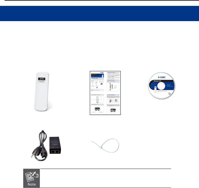
1.1 Package Contents
Thank you for choosing PLANET WNAP-7320. Before installing the AP, please verify the contents inside the package box.
WNAP-7320 Wireless AP |
|
Quick Installation Guide |
|
CD-ROM |
(User Manual included)
PoE Injector & Power Cord |
|
Mounting Tie x 2 |
If there is any item missed or damaged, please contact the seller immediately.
-1-
User Manual of WNAP-7320
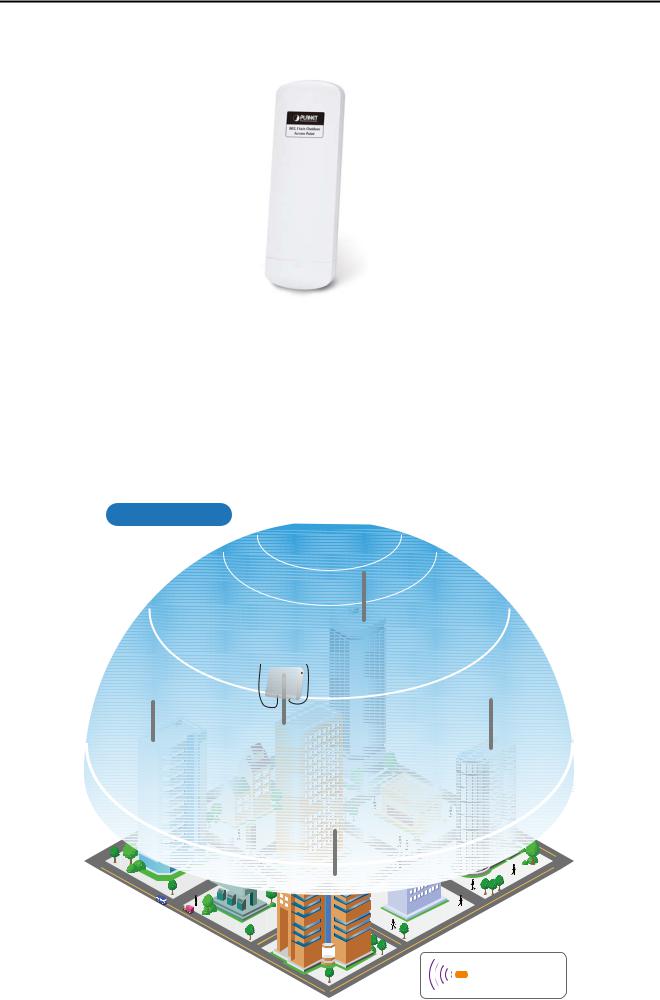
1.2 Product Description
High Power Outdoor Wireless Coverage
PLANET Technology introduces the latest high power outdoor wireless LAN solution - the 300Mbps outdoor wireless AP, WNAP-7320. It provides higher transmit power, better performance, widely coverage and stable connection than standard outdoor wireless AP. As an IEEE 802.11a/n compliant wireless device, the WNAP-7320 is able to give stable and efficient wireless performance for long distance application; while designed with IEEE 802.11n standard and 2T2R MIMO technology makes it possible to deliver six times faster data rate up to 300Mbps than normal 802.11a wireless device. It also features adjustable output power up to 500mW to extend higher coverage in outdoor long range application.
Wi-Fi City
WNAP-7320
a/n
a/n Antenna a/n
WNAP-7320 |
AP |
|
WNAP-7320 |
a/n |
a/n |

 a/n
a/n


 WNAP-7320
a/n |
5GHz 802.11a/n |
-2-
User Manual of WNAP-7320
Multiple Operating & Wireless Modes
The WNAP-7320 supports multiple wireless communication connectivity (AP / Client CPE / WDS PtP / WDS PtMP / Repeater) allowing for various application requirements and thus it gives users more comprehensive experience when using the WNAP-7320. It helps users to easily build a wireless network and extend the wireless range of existing wireless network.
The WNAP-7320 also supports WISP mode, so CPE users could easily connect to Internet via WISP provider or connect to a wired network.
AP-Router Mode
Internet
001101010 |
WAN |
a/n |
|
Cable/xDSL
Modem
WNAP-7320
 AP Router Mode
WDS Bridge-PtP Mode
a/n
Client
a/n
Client
|
WNAP-7320 |
WNAP-7320 |
|
Clients |
|
|
Clients |
|
a/n |
a/n |
|
Switch |
Bridge - PtP Mode |
Switch |
|
|
Client Router Mode (WISP) |
|
|
Internet |
|
WNAP-7320 |
|
|
|
|
|
|
|
|
Client |
|
a/n |
a/n |
|
Wireless Internet |
LAN |
|
|
Service Provider |
|
||
|
|
||
 WISP Mode
WDS Repeater Mode |
|
|
|
Internet |
WNAP-7320 |
|
|
a/n |
a/n |
|
Client |
|
|
|
|
WNAP-7320 |
|
|
|
WDS Repeater Mode |
|
Switch |
Clients |
|
|
||
WDS Bridge-PtMP Mode |
|
||
WNAP-7320 |
|
|
|
|
a/n |
|
|
Clients |
|
Switch |
Clients |
a/n |
WNAP-7320 |
|
|
|
|
||
|
a/n |
Switch |
|
|
|
Clients |
|
Switch |
Bridge - PtMP Mode |
||
Client Bridge Mode |
|
|
|
Internet |
|
|
|
a/n |
a/n |
|
|
|
|
LAN |
|
Wireless AP/Router |
|
IP Camera |
|
WNAP-7320
 Client Bridge Mode
|
100Base-TX UTP |
|
|
a/n |
5GHz 802.11a/n |
Advanced Security and Management
In aspect of security, besides 64/128bit WEP encryption, the WNAP-7320 integrates WPA / WPA2, WPA-PSK / WPA2-PSK and 802.1x authority to secure and protect your wireless LAN. The wireless MAC filtering and SSID broadcast control consolidate the wireless network security and prevent unauthorized wireless connection. To fulfill enterprise and various applications demand, the WNAP-7320 enhances security and management features such as providing multiple SSID support.
-3-

User Manual of WNAP-7320
Perfect Solution for Outdoor Environment
The WNAP-7320 is perfectly suitable in outdoor environments and exposed locations. By designing with IP55 and Outdoor UV Stabilized Enclosure, the WNAP-7320 can perform normally under rigorous weather conditions including heavy rain, wind and snow. Moreover, the WNAP-7320 is rated to operate at the temperature from -30 to 75 Degree C; thus it can operate more stably than general outdoor equipments. It is the best way using the WNAP-7320 to build outdoor wireless access applications between buildings on campuses, business, rural areas and etc.
Flexible Deployment with PoE Feature
With the proprietary Power over Ethernet (PoE) design, the WNAP-7320 can be easily applied in the areas where power outlets are not available. It thus reduces the needs of extra cables and dedicated electrical outlets on the wall, ceiling or any other places where are difficult to reach. It enables the wireless LAN deployment becomes more flexible and worries free from the power outlet locations. It is the best way using the WNAP-7320 to build outdoor wireless access applications between buildings on campuses, business, rural areas and etc.
Easy Installation & Management
With user-friendly Web UI and step by step Setup Wizard, the WNAP-7320 is easier to install, even for users who never experience setting up a wireless network. Furthermore, with SNMP-Based management interface, the WNAP-7320 is convenient to be managed and configured remotely.
-4-

User Manual of WNAP-7320
1.3Product Features
Industrial Compliant Wireless LAN & LAN
Compliant with IEEE 802.11n wireless technology capable of up to 300Mbps data rate
Backward compatible with 802.11a standard
Equipped with 10/100Mbps RJ-45 Ports for LAN & WAN, Auto MDI/ MDI-X supported
Fixed-network Broadband AP
Supported connection types: Dynamic IP / Static IP / PPPoE / PPTP / L2TP / IPSec
Supports Virtual Server, DMZ for various networking applications
Supports DHCP Server, UPnP, Dynamic DNS
RF Interface Characteristics
Built-in 14dBi Dual-Polarization Antenna
High Output Power up to 500mW with multiple adjustable transmit power control
Outdoor Environmental Characteristics
Outdoor UV Stabilized Enclosure, IP55 Protection Grade
Passive Power over Ethernet design
Operating Temperature: -30~75 Degree C
Multiple Operation & Wireless Mode
Multiple Operation Modes: Bridge, Gateway, WISP
Multiple Wireless Modes: AP, Client CPE (WISP), WDS PtP, WDS PtMP, Repeater
Supports Dual-SSID allowing users to access different networks through one single AP
Supports WMM (Wi-Fi Multimedia)
Secure Network Connection
Supports Software Wi-Fi Protected Setup (WPS)
Advanced security: 64/128-bit WEP, WPA / WPA2, WPA-PSK / WPA2-PSK (TKIP/AES), and 802.1x Authentication
Supports NAT firewall features, with SPI function to protect against DoS attacks
Supports IP / Protocol-based access control and MAC Filtering
Easy Installation & Management
Web-Based UI and Quick Setup Wizard for easy configuration
Remote Management allows configuration from a remote site
SNMP-Based management interface
System status monitoring includes DHCP Client, System Log
-5-

User Manual of WNAP-7320
1.4 Product Specification
|
Product |
WNAP-7320 |
|
5GHz 300Mbps 802.11a/n Wireless Outdoor Access Point |
|
|
|
|
|
Hardware Specifications |
|
|
|
|
|
|
IEEE 802.11a/n Wireless LAN |
|
|
||
|
|
IEEE 802.11i Wireless Security |
|
|
||
|
Standard support |
IEEE 802.3 10Base-T Ethernet |
|
|
||
|
|
IEEE 802.3u 100Base-TX Ethernet |
|
|
||
|
|
IEEE 802.3x Flow Control |
|
|
||
|
Memory |
32 Mbytes DDR SDRAM |
|
|
||
|
8 Mbytes Flash |
|
|
|
|
|
|
|
|
|
|
|
|
|
|
Wireless IEEE802.11a/n, 2T2R |
|
|
||
|
Interface |
LAN: 1 x 10/100Base-TX, Auto-MDI/MDIX |
|
|||
|
|
WAN: 1 x 10/100Base-TX, Auto-MDI/MDIX |
|
|||
|
|
Built-in 14dBi Dual-Polarization Antenna |
|
|||
|
Antenna |
- Horizontal: 45 degree |
|
|
||
|
|
- Vertical: 60 degree |
|
|
||
|
Wireless RF Specifications |
|
|
|
|
|
|
Wireless Technology |
IEEE 802.11a |
|
|
|
|
|
IEEE 802.11n |
|
|
|
|
|
|
|
|
|
|
|
|
|
|
IEEE 802.11a: 54, 48, 36, 24, 18, 12, 9 and 6Mbps |
|
|||
|
Data Rate |
IEEE 802.11n (20MHz): up to 150Mbps |
|
|||
|
|
IEEE 802.11n (40MHz): up to 300Mbp |
|
|
||
|
Media Access Control |
CSMA / CA |
|
|
|
|
|
Modulation |
Transmission / Emission Type: OFDM |
|
|
||
|
Data modulation type: OFDM with BPSK, QPSK, 16-QAM, 64-QAM |
|||||
|
|
|||||
|
Frequency Band |
5.180GHz ~ 5.825GHz |
|
|
||
|
|
5.180GHz |
CH36 |
|
5.580GHz |
CH116 |
|
|
5.200GHz |
CH40 |
|
5.600GHz |
CH120 |
|
|
5.220GHz |
CH44 |
|
5.620GHz |
CH124 |
|
|
5.240GHz |
CH48 |
|
5.640GHz |
CH128 |
|
|
5.260GHz |
CH52 |
|
5.660GHz |
CH132 |
|
|
5.280GHz |
CH56 |
|
5.680GHz |
CH136 |
|
Operating Channel |
5.300GHz |
CH60 |
|
5.700GHz |
CH140 |
|
|
5.320GHz |
CH64 |
|
5.745GHz |
CH149 |
|
|
|
|
|
|
|
|
|
5.500GHz |
CH100 |
|
5.765GHz |
CH153 |
|
|
5.520GHz |
CH104 |
|
5.785GHz |
CH157 |
|
|
5.540GHz |
CH108 |
|
5.805GHz |
CH161 |
|
|
5.560GHz |
CH112 |
|
5.825GHz |
CH165 |
|
|
*The above 24 channels are defined in theory. The actual application will vary |
||||
|
|
depends on the regulation in different regions and countries. |
||||
|
RF Output Power |
IEEE 802.11a: 27 ± 1dBm |
|
|
||
-6-

User Manual of WNAP-7320
|
IEEE 802.11n: 24 ± 1dBm |
|
Receiver Sensitivity |
IEEE 802.11a: -92 ~ -73dBm @ 6Mbps ~ 54Mbps |
|
IEEE 802.11n: -94 ~ -73dBm @ MCS0 ~ MCS15 |
||
|
||
Output Power Control |
3~27dBm |
|
Software Features |
|
|
LAN |
Built-in DHCP server supporting static IP address distributing |
|
Supports 802.1d STP (Spanning Tree) |
||
|
||
|
Static IP |
|
|
Dynamic IP |
|
WAN |
PPPoE |
|
PPTP |
||
|
||
|
L2TP |
|
|
IPSec |
|
|
Bridge |
|
Operating Mode |
Gateway |
|
|
WISP |
|
|
NAT firewall with SPI (Stateful Packet Inspection) |
|
Firewall |
Built-in NAT server supporting Virtual Server and DMZ |
|
|
Built-in firewall with Port / IP address / MAC / URL filtering |
|
|
AP |
|
|
Client |
|
Wireless Mode |
WDS PTP |
|
|
WDS PTMP |
|
|
WDS Repeater (AP+WDS) |
|
Channel Width |
20MHz / 40MHz |
|
Wireless Isolation |
Enable it to isolate each connected wireless clients from communicating with |
|
each other mutually. |
||
|
||
Encryption Type |
64/128-bits WEP, WPA, WPA-PSK, WPA2, WPA2-PSK, 802.1X |
|
|
Provides wireless LAN ACL (Access Control List) filtering |
|
Wireless Security |
Wireless MAC address filtering |
|
Supports WPS (WIFI Protected Setup ) |
||
|
||
|
Enable / Disable SSID Broadcast |
|
Multiple SSID |
Up to 2 |
|
Max. Wireless Client |
40 |
|
Max. WDS AP |
8 |
|
Max. Wired Client |
60 |
|
WMM |
Supports Wi-Fi Multimedia |
|
QoS |
Supports Quality of Service for bandwidth control |
|
NTP |
Network Time Management |
|
Management |
Web UI, DHCP Client, Configuration Backup & Restore, Dynamic DNS, SNMP |
|
Diagnostic tool |
System Log, Ping Watchdog |
|
Mechanical & Power |
|
|
IP Rate |
IP55 |
-7-

User Manual of WNAP-7320
Material |
Outdoor UV Stabilized Enclosure |
||
Dimension (W x D x H) |
275 x 93 x 45mm |
|
|
Weight |
336 ± 5g |
|
|
Installation |
Pole mounting or Wall mounting |
||
|
LAN |
24V DC, 0.5A/ Passive PoE |
|
Power Requirements |
|
Pin 4,5 VDC+ |
|
|
|
Pin 7,8 VDC- |
|
Power Consumption |
7.68W |
|
|
Environment & Certification |
|
||
Operation Temperature |
-30~75 Degree C |
|
|
Operating Humidity |
10~95% non-condensing |
||
Regulatory |
CE / RoHS |
|
|
Accessory |
|
|
|
|
24V DC Passive PoE injector & Power cord x 1 |
||
Standard Accessories |
Mounting Tie x 2 |
||
Quick Installation Guide x 1 |
|||
|
|||
|
CD (User’s Manual, Quick Installation Guide) x 1 |
||
-8-
User Manual of WNAP-7320
Chapter 2.Hardware Installation
Please follow the instructions below to connect WNAP-7320 to the existing network devices and your computers.
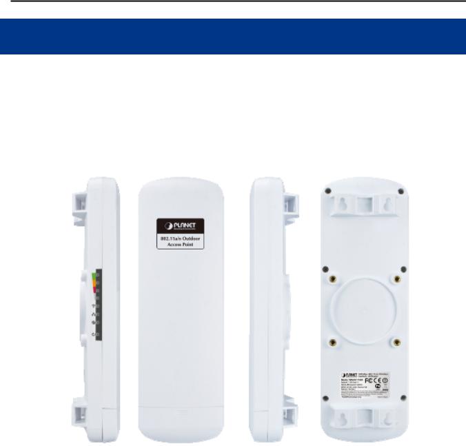
2.1 Hardware Description
Dimension: 275 x 93 x 45mm (W x D x H)
Figure 2-1 Three-way View
-9-
User Manual of WNAP-7320
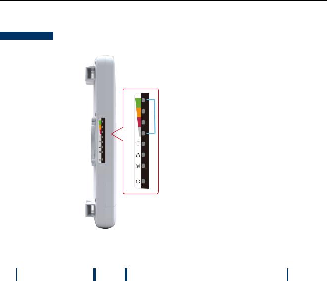
2.1.1 The Side Panel – LED
Side Panel - LED
 Signal Indicator
 Wireless LED
 LAN Port LED
 WAN Port LED
 Power LED
|
|
|
|
|
Figure 2-2 LED |
|
|
|
|
|
|
LED definition |
|
|
|
||
|
|
|
|
|
|
|
LED |
State |
|
Meaning |
|
|
Power |
On |
|
System On |
|
|
|
|
|
||
|
Off |
|
System Off |
||
|
|
|
|
||
|
|
|
|
|
|
|
Signal Indicator |
On |
|
Indicates the wireless signal strength of remote AP |
|
|
|
|
|
|
|
|
(Client/Repeater Mode) |
Off |
|
No remote wireless signal |
|
|
|
|
|
|
|
|
Wireless |
On |
|
Wi-Fi On |
|
|
|
|
|
||
|
Off |
|
Wi-Fi Off |
||
|
|
|
|
||
|
|
|
|
|
|
|
WAN Port |
On |
|
Port linked. |
|
|
|
|
|
||
|
Off |
|
No link. |
||
|
|
|
|
||
|
|
|
|
|
|
|
LAN Port |
On |
|
Port linked. |
|
|
|
|
|
|
|
|
|
|
Off |
|
No link. |
|
|
|
|
|
|
|
|
|
|
Table 2-1 The LED indication |
|
-10-
User Manual of WNAP-7320
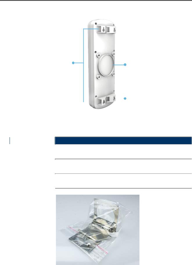
2.1.2 The Rear Panel – Mounting Design
 Wall Mount Hole
Pole Mount Holders |
L-Mount (Option) |
|
|
|
|
|
|
|
|
Wall Mount Hole |
|
|
|
|
|
|
|
|
|
|
|
|
|
|
||
|
|
|
Figure 2-3 Mounting Design |
||||
|
|
|
|
|
|
|
|
Mounting Design |
|
|
|
|
|
||
|
|
|
|
|
|
|
|
|
LED |
Meaning |
|||||
|
Pole Mount Holders |
Use the "Mounting Ties" shipped in the box with the WNAP-7320 for Pole |
|||||
|
Mounting. |
||||||
|
|
|
|||||
|
|
|
Use the optional "L-Mount Kit" for Pole Mounting with adjustable angle. |
||||
|
L-Mount (Option) |
||||||
|
The L-Mount-Kit must be purchased separately. |
||||||
|
|
|
|||||
|
|
Use suitable screws for Wall Mounting. The screws did not supply with the |
|||||
|
Wall Mount Hole |
||||||
|
|
|
WNAP-7320. |
||||
|
|
|
|
|
|
|
|
Figure 2-4 L-Mount Kit
-11-
User Manual of WNAP-7320
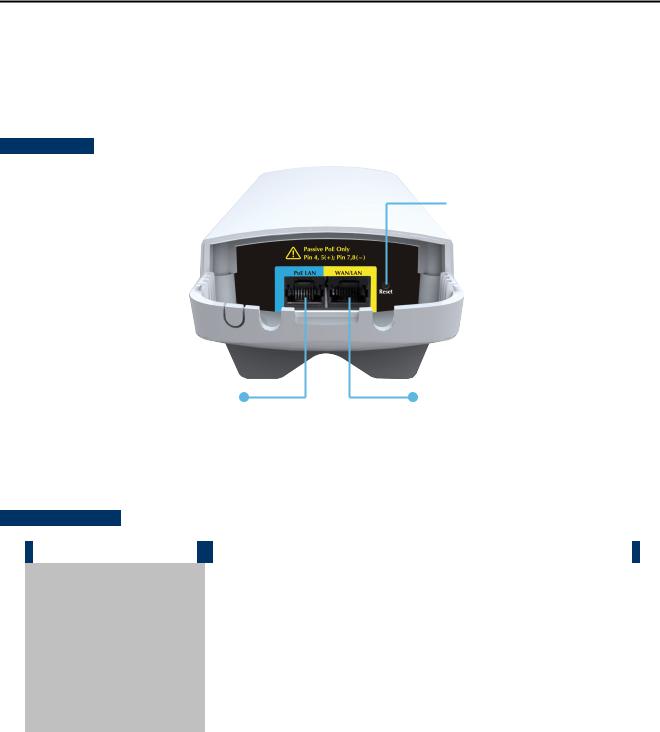
2.1.3 The Bottom Panel – Port
The Bottom panel provides the physical connectors connected to the power adapter and any other network devices. Figure 2-5 shows the Bottom panel of WNAP-7320.
Bottom Panel
 Reset
Reset
LAN (Passive PoE) |
WAN (Router Mode) |
Pin4,5(+); Pin 7, 8(-) |
LAN (Bridge Mode) |
|
Figure 2-5 Bottom Panel |
Interface definition
|
Interface |
|
|
Description |
|
|
|
|
|
10/100Mbps RJ-45 port , Auto MDI/ MDI-X & Passive PoE supported |
|
|
LAN (Passive PoE) |
|
|
|
|
|
|
Connect LAN port to the PoE injector to power on the device. |
|
||
|
|
|
|
||
|
|
|
|
|
|
|
|
|
|
10/100Mbps RJ-45 port , Auto MDI/ MDI-X |
|
|
|
|
|
Connect this port to the xDSL modem in router mode. |
|
|
WAN/LAN |
|
|
|
|
|
|
|
|
Connect this port to the network equipment in bridge mode. |
|
|
|
|
|
|
|
|
|
|
|
|
|
|
Reset |
|
Press Reset button over 5 seconds to return factory default setting. |
|
|
|
|
|
|
|
|
|
|
|
|
Table 2-2 The Interface indication |
|
-12-
User Manual of WNAP-7320
Chapter 3.Connecting to the AP
3.1 Preparation before Installation
3.1.1 Professional Installation Required
Please seek assistance from a professional installer who is well trained in the RF installation and knowledgeable in the local regulations.
3.1.2Safety Precautions
1.To keep you safe and install the hardware properly, please read and follow these safety precautions.
2.If you are installing WNAP-7320 for the first time, for your safety as well as others’, please seek assistance from a professional installer who has received safety training on the hazards involved.
3.Keep safety as well as performance in mind when selecting your installation site, especially where there are electric power and phone lines.
4.When installing WNAP-7320, please note the following things:
Do not use a metal ladder;
Do not work on a wet or windy day;
Wear shoes with rubber soles and heels, rubber gloves, long sleeved shirt or jacket.
5.When the system is operational, avoid standing directly in front of it. Strong RF fields are present when the transmitter is on.
3.2Installation Precautions
Users MUST use a proper and well-installed surge arrestor and grounding kit with WNAP-7320; otherwise, a random lightening could easily cause fatal damage to WNAP-7320. EMD (Lightning)
DAMAGE IS NOT COVERED UNDER WARRANTY.
Users MUST use the “Power cord & PoE Injector” shipped in the box with the WNAP-7320. Use of other options will cause damage to the WNAP-7320.
-13-
User Manual of WNAP-7320
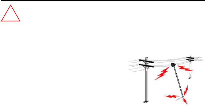
!OUTDOOR INSTALLATION WARNING
IMPORTANT SAFETY PRECAUTIONS:
LIVES MAY BE AT RISK! Carefully observe these instructions and any special instructions that are included with the
equipment you are installing.
CONTACTING POWER LINES CAN BE LETHAL. Make sure no power lines are anywhere where possible contact can be made. Antennas, masts, towers, guy wires or cables may lean or fall and contact these limes. People may be injured or killed if they are touching or holding any part of equipment when it contacts electric lines. Make sure there is NO possibility that equipment or personnel can come in contact directly or indirectly with power lines.
Assume all overhead lines are power lines.
The horizontal distance from a tower, mast or antenna to the nearest power line should be at least twice the total length of the mast/antenna combination. This will ensure that the mast will not contact power if it falls either during installation or later.
TO AVOID FALLING, USE SAFE PROCEDURES WHEN WORKING AT HEIGHTS ABOVE GROUND.
Select equipment locations that will allow safe, simple equipment installation.
Don’t work alone. A friend or co-worker can save your life if an accident happens.
Use approved non-conducting lasers and other safety equipment. Make sure all equipment is in good repair.
If a tower or mast begins falling, don’t attempt to catch it. Stand back and let it fall.
If anything such as a wire or mast does come in contact with a power line, DON’T TOUCH IT OR ATTEMPT TO MOVE IT. Instead, save your life by calling the power company.
Don’t attempt to erect antennas or towers on windy days.
MAKE SURE ALL TOWERS AND MASTS ARE SECURELY GROUNDED, AND ELECTRICAL CABLES CONNECTED TO
ANTENNAS HAVE LIGHTNING ARRESTORS. This will help prevent fire damage or human injury in case of lightning, static
build-up, or short circuit within equipment connected to the antenna.
The base of the antenna mast or tower must be connected directly to the building protective ground or to one or more approved grounding rods, using 1 OAWG ground wire and corrosion-resistant connectors.
Refer to the National Electrical Code for grounding details.
IF A PERSON COMES IN CONTACT WITH ELECTRICAL POWER, AND CANNOT MOVE:
DON’T TOUCH THAT PERSON, OR YOU MAY BE ELECTROCUTED.
Use a non-conductive dry board, stick or rope to push or drag them so they no longer are in contact with electrical power.
Once they are no longer contacting electrical power, administer CPR if you are certified, and make sure that emergency
medical aid has been requested.
-14-
User Manual of WNAP-7320
3.3 Installing the AP
Please install the AP according to the following steps. Don't forget to pull out the power plug and keep your hands dry.
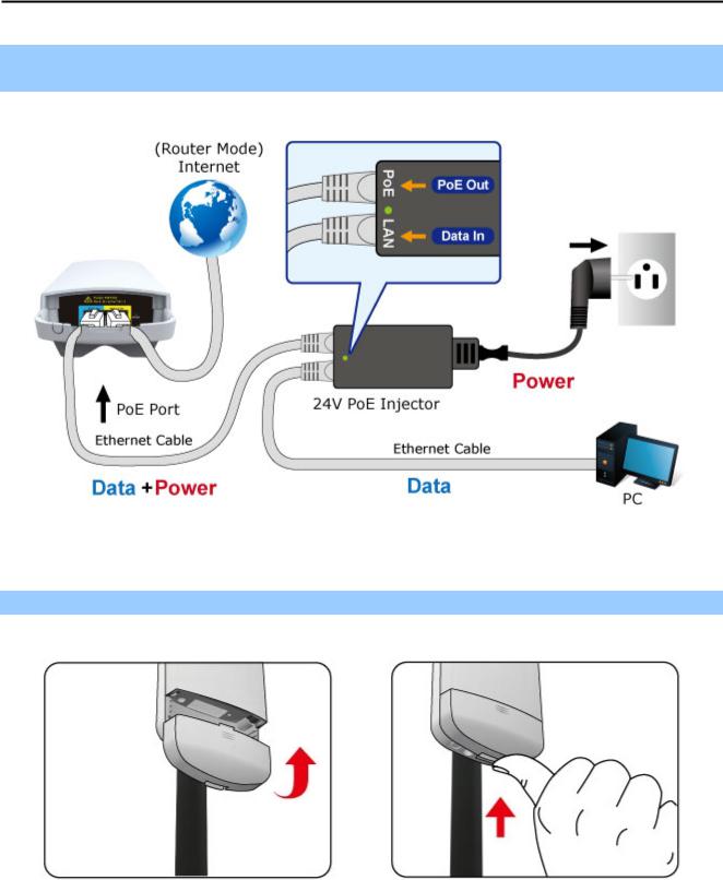
Step 1. Push the latch in the bottom of WNAP-7320 to remove the sliding cover.
Figure 3-1
Step 2. Plug the RJ-45 Ethernet cable into the PoE LAN Port of WNAP-7320.
Figure 3-2
RJ-45 8P8C Ethernet cable is required.
-15-
User Manual of WNAP-7320
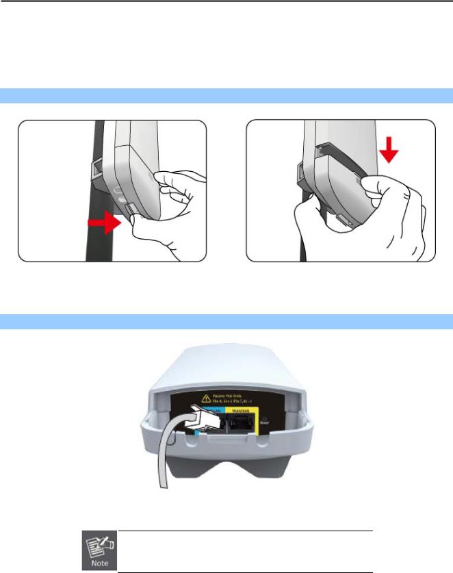
Step 3. Take out the power cord and PoE injector, plug the power cord into the DC port and plug the other side of the RJ-45 cable in the Step 2 into the POE port of the PoE injector.
Figure 3-3
Step 4. Slide the cover back to seal the bottom of the WNAP-7320 to finish the installation.
Figure 3-4
-16-
User Manual of WNAP-7320
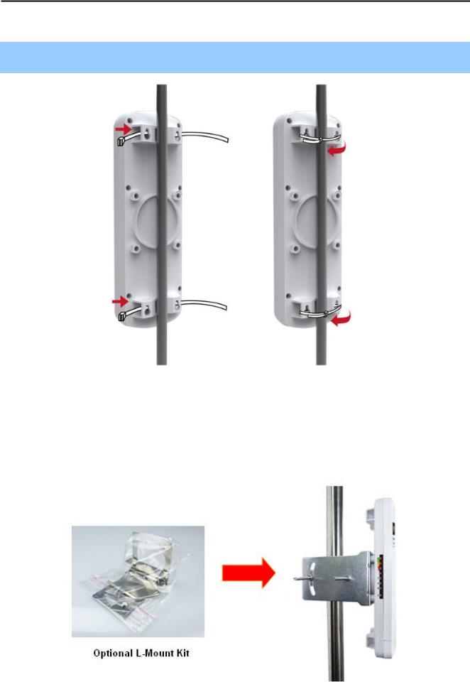
3.4 Standard Pole Mounting
Place the straps through the slots on the back of the WNAP-7320 and then around the pole. Tighten the straps to secure the WNAP-7320.
Figure 3-5 Pole Mounting
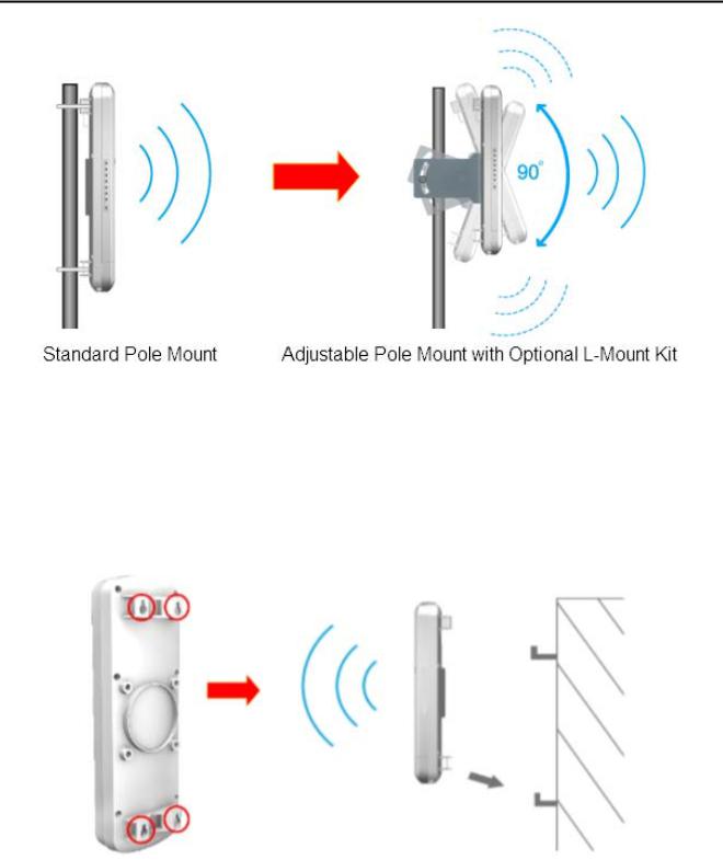
3.5 Adjustable Pole Mounting
The WNAP-7320 has L-Mount design in the rear panel which provide flexible mounting option for various environments.
Figure 3-5 L-Mount
-17-
User Manual of WNAP-7320
Figure 3-6 L-Mount – Adjustable antenna
3.6 Wall Mounting
There are four Wall Mount Holes in the rear panel of WNAP-7320 which provide wall mounting option for users.
Figure 3-7 Wall Mount
-18-

User Manual of WNAP-7320
Chapter 4. Quick Installation Guide
This chapter will show you how to configure the basic functions of your Wireless AP using Easy Setup within minutes.
A computer with wired Ethernet connection to the Wireless AP is required for the first-time configuration.
4.1 Manual Network Setup - TCP/IP Configuration
The default IP address of the WNAP-7320 is 192.168.1.1. And the default Subnet Mask is 255.255.255.0. These values can be changed as you desire. In this guide, we use all the default values for description.
Connect the WNAP-7320 with your PC by an Ethernet cable plugging in LAN port of PoE injector in one side and in LAN port of PC in the other side. Please power on the WNAP-7320 by PoE from PoE injector or PoE switch.
In the following sections, we’ll introduce how to install and configure the TCP/IP correctly in Windows XP. And the procedures in other operating systems are similar. First, make sure your Ethernet Adapter is working, and refer to the Ethernet adapter’s manual if needed.
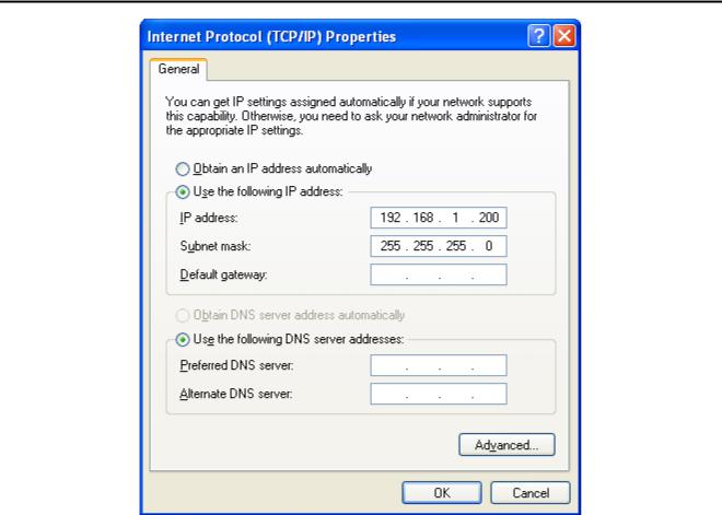
4.1.1 Configure the IP Address Manually
Summary:
Set up the TCP/IP Protocol for your PC.
Configure the network parameters. The IP address is 192.168.1.xxx ("xxx" is any number from 2 to 254), Subnet Mask is 255.255.255.0, and Gateway is 192.168.1.1 (The AP's default IP address)
1Select Use the following IP address radio button.
2If the AP's LAN IP address is 192.168.1.1, enter IP address 192.168.1.x (x is from 2 to 254), and Subnet mask 255.255.255.0.
3Select Use the following DNS server addresses radio button. In the Preferred DNS Server field, you can enter the DNS server IP address which has been provided by your ISP
-19-
User Manual of WNAP-7320
Figure 4-1
Now click OK to save your settings.
Now, you can run the Ping command in the command prompt to verify the network connection between your PC and the AP. The following example is in Windows XP OS. Please follow the steps below:
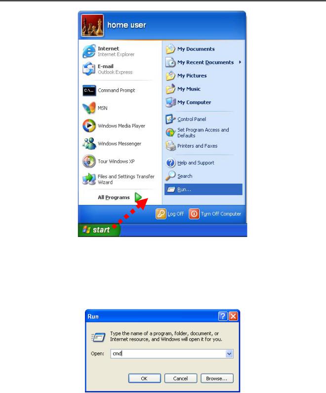
1.Click on Start > Run.
-20-
User Manual of WNAP-7320
Figure 4-2
2.In the run box type “cmd” and click OK. (Windows Vista users type “cmd” in the Start .Search box.)At the prompt.
Figure 4-3
Open a command prompt, and type ping 192.168.1.1, and then press Enter.
If the result displayed is similar to Figure 4-4, it means the connection between your PC and the AP has been established well.
-21-

User Manual of WNAP-7320
Figure 4-4 Success result of Ping command
If the result displayed is similar to Figure 4-5, it means the connection between your PC and the AP has failed.
Figure 4-5 Failure result of Ping command
If the address is 0.0.0.0, check your adapter installation, security settings, and the settings on your AP. Some firewall software programs may block a DHCP request on newly installed adapters.
-22-
 Loading...