


FGSW-2620CS
User’s Manual
24-Port 10/100Mbps + 2Gigabit
TP/SFP Combo Web Samrt Switch
FGSW-2620CS
www.PLANET.com.tw

Trademarks
Copyright PLANET Technology Corp. 2013.
Contents are subject to revision without prior notice.
PLANET is a registered trademark of PLANET Technology Corp. All other trademarks belong to their respective
owners.
Disclaimer
PLANET Technology does not warrant that the hardware will work properly in all environments and applications,
and makes no warranty and representation, either implied or expressed, with respect to the quality, performance,
merchantability, or fitness for a particular purpose.
PLANET has made every effort to ensure that this User’s Manual is accurate; PLANET disclaims liability for any
inaccuracies or omissions that may have occurred.
Information in this User’s Manual is subject to change without notice and does not represent a commitment on the
part of PLANET. PLANET assumes no responsibility for any inaccuracies that may be contained in th is User’s
Manual. PLANET makes no commitment to update or keep current the information in this User’s Manual, and
reserves the right to make improvements to this User’s Manual and/or to the products described in this User’s
Manual, at any time without notice.
If you find information in this manual that is incorrect, misleading, or incomplete, we would appreciate your
comments and suggestions.
User’s Manual of FGSW-2620CS
FCC Warning
This equipment has been tested and found to comply with the limits for a Class A digital device, pursuant to Part
15 of the FCC Rules. These limits are designed to provide reasonable protection agai nst harmful interference
when the equipment is operated in a commercial environment. This equipment generates, uses, and can radiate
radio frequency energy and, if not installed and used in accordance with the Instruction manual, may cause
harmful interference to radio communications. Operation of this equipment in a residential area is likely to cause
harmful interference in which case the user will be required to correct the interference at his own expense.
CE Mark Warning
This is a Class A product. In a domestic environment, this product may cause r adio interference, i n which case
the user may be required to take adequate measures.
Energy Saving Note of the Device
This power required device does not support Standby mode operation.
For energy saving, please remove the power cable to disconnect the device from the power circuit.
Without removing power cable, the device will still consume power from the power source. In view of Saving the
Energy and reducing the unnecessary power consumption, it is strongly suggested to remove the po wer connection for the device if this device is not intended to be active.
WEEE Warning
To avoid the potential effects on the environment and human health as a result of the presenc e of
hazardous substances in electrical and electronic equipment, end users of electrical and electronic
equipment should understand the meaning of the crossed-out wheeled bin symbol. Do not dispose of
WEEE as unsorted municipal waste and have to collect such WEEE separately.
- 2 -

Revision
PLANET 24-Port 10/100Mbps with 2 Gigabit TP / SFP Combo Web Smart Switch User's Manual
FOR MODELS: FGSW-2620CS(V3)
REVISION: 3.0 (O
Part No.: 2080-A81160-001
User’s Manual of FGSW-2620CS
ctober, 2013)
- 3 -

User’s Manual of FGSW-2620CS
TABLE OF CONTENTS
1. INTRODUCTION ...............................................................................6
1.1 CHECKLIST ................................................................................................................................................6
1.2 ABOUT THE SWITCH ...................................................................................................................................6
1.3 FEATURES .................................................................................................................................................7
1.4 SPECIFICATIONS.........................................................................................................................................9
2. HARDWARE DESCRIPTION ............................................................11
2.1 FRONT PANEL..........................................................................................................................................11
2.2 REAR PANEL............................................................................................................................................12
2.3 HARDWARE INSTALLATION ........................................................................................................................ 12
3. SWITCH MANAGEMENT .................................................................17
3.1 OVERVIEW...............................................................................................................................................17
3.2 MANAGEMENT METHOD............................................................................................................................17
3.2.1 Web Management...........................................................................................................................17
3.2.2 PLANET Smart Discovery Utility..................................................................................................... 17
3.3 LOGGING ON TO THE FGSW-2620CS.......................................................................................................19
4. WEB MANAGEMENT........................................................................20
4.1 LOGIN TO THE SWITCH..............................................................................................................................20
4.2 SYSTEM...................................................................................................................................................21
4.2.1 System Information.........................................................................................................................22
4.2.2 IP Configuration..............................................................................................................................23
4.2.3 Password Setting............................................................................................................................23
4.2.4 Factory Default................................................................................................................................ 24
4.2.5 Firmware Update ............................................................................................................................24
4.2.6 Reboot.............................................................................................................................................26
4.3 PORT MANAGEMENT ................................................................................................................................27
4.3.1 Port Configuration...........................................................................................................................28
4.3.2 Port Mirroring ..................................................................................................................................30
4.3.3 Bandwidth Control...........................................................................................................................31
4.3.4 Broadcast Storm Control.................................................................................................................32
4.3.5 Port Statistics..................................................................................................................................32
4.4 VLAN SETTING........................................................................................................................................34
4.4.1 802.1Q VLAN..................................................................................................................................37
4.4.2 802.1Q VLAN Setting......................................................................................................................40
4.4.3 Port-based VLAN............................................................................................................................47
4.4.4 Port-based VLAN Setting................................................................................................................48
4.4.5 MTU VLAN......................................................................................................................................48
4.5 TRUNK..................................................................................................................................................... 50
- 4 -

User’s Manual of FGSW-2620CS
4.6 QOS SETTING..........................................................................................................................................52
4.6.1 Priority Mode...................................................................................................................................53
4.6.2 Class of Service Configuration........................................................................................................54
4.6.3 TCP / UDP Port-based QoS ...........................................................................................................56
4.7 SECURITY FILTER.....................................................................................................................................58
4.7.1 MAC Address Filter.........................................................................................................................59
4.7.2 TCP / UDP Filter .............................................................................................................................60
4.8 SPANNING TREE.......................................................................................................................................62
4.8.1 STP Bridge Setting .........................................................................................................................63
4.8.2 STP Port Setting .............................................................................................................................65
4.8.3 Loopback Detection Setting............................................................................................................67
4.9 DHCP RELAY AGENT...............................................................................................................................69
4.9.1 DHCP Relay Agent.........................................................................................................................70
4.9.2 Relay Server ...................................................................................................................................70
4.9.3 VLAN Map Relay Agent..................................................................................................................71
4.10 MISC OPERATION...................................................................................................................................72
4.11 BACKUP/RECOVERY...............................................................................................................................73
4.12 SNMP SETTINGS...................................................................................................................................74
4.13 LOGOUT ................................................................................................................................................75
5. SWITCH OPERATION......................................................................76
5.1 ADDRESS TABLE ......................................................................................................................................76
5.2 LEARNING................................................................................................................................................76
5.3 FORWARDING & FILTERING.......................................................................................................................76
5.4 STORE-AND-FORWARD.............................................................................................................................76
5.5 AUTO-NEGOTIATION.................................................................................................................................77
6. TROUBLESHOOTING.......................................................................78
APPENDIX: A NETWORKING CONNECTION.........................................79
A.1 SWITCH‘S RJ-45 PIN ASSIGNMENTS.........................................................................................................79
A.2 RJ-45 CABLE PIN ASSIGNMENT ................................................................................................................. 79
- 5 -

User’s Manual of FGSW-2620CS
1. INTRODUCTION
1.1 Checklist
Check the contents of your package for the following parts:
FGSW-2620CS x 1
Quick Installation Guide x 1
User's Manual CD x 1
Power Cord x 1
Rubber Feet x 4
Two Rack-mount Brackets with Attachment Screws x 1
If any of these pieces are missing or damaged, please contact your dealer immediately; if possibl e, retain the carton
including the original packing material, and use them again to repack the product in case there is a need to return it to us
for repair.
In the following section, the term “Web Smart Switch” means the FGSW-2620CS whereas the term “switch” can be
any third switches.
1.2 About the Switch
The FGSW-2620CS provides 24 10/100Mbps Fast Ethernet ports and two Gigabit Ethernet ports, either TP or
SFP per port. The two Gigabit ports either can be 1000Base-T for 10/100/1000Mbps or 1000Base-SX/LX
through SFP (Small Factor Pluggable) interfaces. The distance can be extended from 100 meters (TP), and
550 meters (Multi-mode fiber), up to above 10/20/30/40/50/70/120 kilometers (Single-mode fiber).
The FGSW-2620CS is equipped with non-blocking 8.8Gbps backplane, greatly simplifies the t asks of upgrading your LAN for catering to increasing bandwidth demands.
For efficient management, the FGSW-2620CS 24-Port 10/100Mbps + 2 Gigabit TP / SFP Combo Web Smart
Switch is equipped with remote Web interface. The FGSW-2620CS can be programmed for advan ced swi t ch
management functions such as port configuration, port-based / IEEE 802.1Q / MTU VLAN, port mirroring, port
trunk, QoS, bandwidth control, broadcast storm control, STP, RSTP, configuration backup/recovery, MAC
address / TCP & UDP filter and IGMP Snooping v1/v2.
The FGSW-2620CS provides port-based / IEEE 802.1Q / MTU VLAN (port based / IEEE 802.1Q VLAN including overlapping). The VLAN groups allowed on the FGSW-2620CS, will be maximally up to 26 for
port-based / 32 for IEEE 802.1Q VLAN groups. Also the MTU VLAN divides port 1 to port 24 as separate LAN
group and only can access the public port 25,26 or port 26. Via supporting port trunking, the FGSW-2620CS
allows the operation of a high-speed trunk combining multiple ports. The FGSW-2620CS also provides two
groups of up to 4-ports 10/ 100Base-TX trunk support, up to 800Mbps bandwidth per trunk and 1 group of
2-Port 10/100/1000Mbps trunk support, up to 2000Mbps band width per trunk, and it supports fai l-over as well.
With its Auto-Negotiation capability, all the RJ-45/UTP ports of Web Smart Switch can be configured to speeds
of 10/20Mbps / 100/200Mbps (Fast Ethernet) and 1000/2000Mbps (Gigabit Ethernet) automatically. In addition, the products are equipped with the MDI/MDI-X auto detection for easily plug and play connection,
regardless of cabling types -- straight-through or crossover.
- 6 -
User’s Manual of FGSW-2620CS
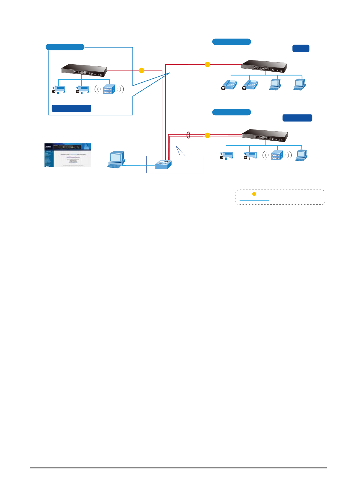
20F
FGSW-2620CS
IP Surveillance Wireless AP
IGMP Snooping
Web Management
Management Client
2 km
1000
Backbone
Fiber Switch
2 km
1000
2 km
1000
19F
QoS
FGSW-2620CS
VoIP VoIP
4F
PC
PC
Port Trunk
FGSW-2620CS
IP Surveillance Wireless AP PC
1000
1000Base-SX/LX Fiber-optic
100Base-TX UTP
1.3 Features
◆ Complies with the IEEE 802.3, IEEE 802.3u, IEEE 802.3ab, IEEE 802.3z Gigabit Ethernet standard
◆ 24 10/100Mbps Fast Ethernet ports
◆ 2 10/100/1000Mbps ports share with 2 SFP ports
◆ Each Switching port supports auto-negotiation with 10/20, 100/200Mbps (Fast Ethernet) , 1000/2000Mbps (Gigabit
Ethernet) supported
◆ Auto-MDI/MDI-X detection on each RJ-45 port
◆ Prevents packet loss with back pressure (half-duplex) and IEEE 802.3x pause frame flow control (full-duplex)
◆ High performance Store and Forward architecture, broadcast storm control, runt/CRC filtering eliminates erro-
neous packets to optimize the network bandwidth
◆ 4K MAC address table, automatic source address learning and ageing
◆ 2.75Mb embedded memory for packet buffers
◆ Remote Web interface for Switch management and setup
◆ Broadcast Storm Control support
◆ Supports up to 26 port-based VLAN groups / 32 IEEE 802.1Q VLAN groups / MTU VLAN
◆ Supports up to 2 Trunk groups, each trunk for up to maximum 4 port with 800Mbps bandwidth
◆ Supports IEEE 802.1D Spanning Tree / IEEE 802.1w Rapid Spanning Tree protocol
◆ Supports QoS , bandwidth control and MAC address filter / TCP & UDP filter on each port
◆ Supports SNMP v1, port mirroring function and IGMP Snooping v1 / v2
◆ Supports DHCP Option82 and DHCP Relay
◆ Firmware upgrade through Web interface
◆ Configuration upload / download through Web interface
◆ Password setting, IP setting and device description setting through Planet Smart discovery utility
- 7 -

◆ 19-inch rack mount size
◆ Internal full-ranging power supply suitable for worldwide use
◆ EMI standards complies with FCC, CE class A
User’s Manual of FGSW-2620CS
- 8 -
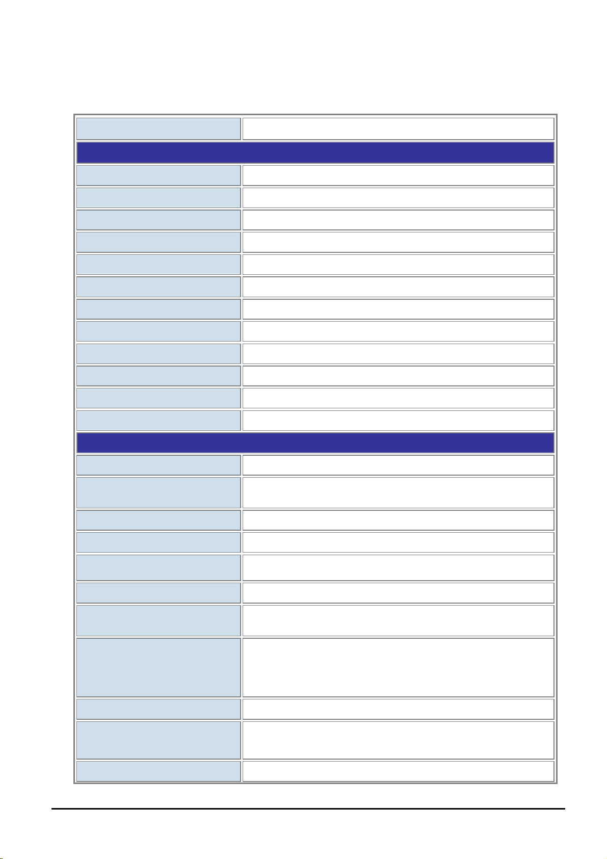
1.4 Specifications
User’s Manual of FGSW-2620CS
Model
Hardware Specifications
Ports
Gigabit Ports
Switch Processing Scheme
Throughput (packet per second)
Switch Fabric
Address Table
Share Data Buffer
Flow Control
Dimensions
Weight
Power Requirements
Power Consumption / Dissipation
FGSW-2620CS
24 10/100Base-TX RJ-45 Auto-MDI/MDI-X interfaces
2 10/100/1000Mbps ports share with 2 SFP interfaces
Store-and-Forward
6.54Mpps@64Bytes
8.8Gbps
4K entries
2.75Mb embedded memory for packet buffers
Back pressure for half duplex, IEEE 802.3x pause frame for full duplex
440 x 120 x 44 mm (1U height)
1.61 kg
100~240V AC, 50-60 Hz, 0.5A
19.6 watts / 66.9BTU
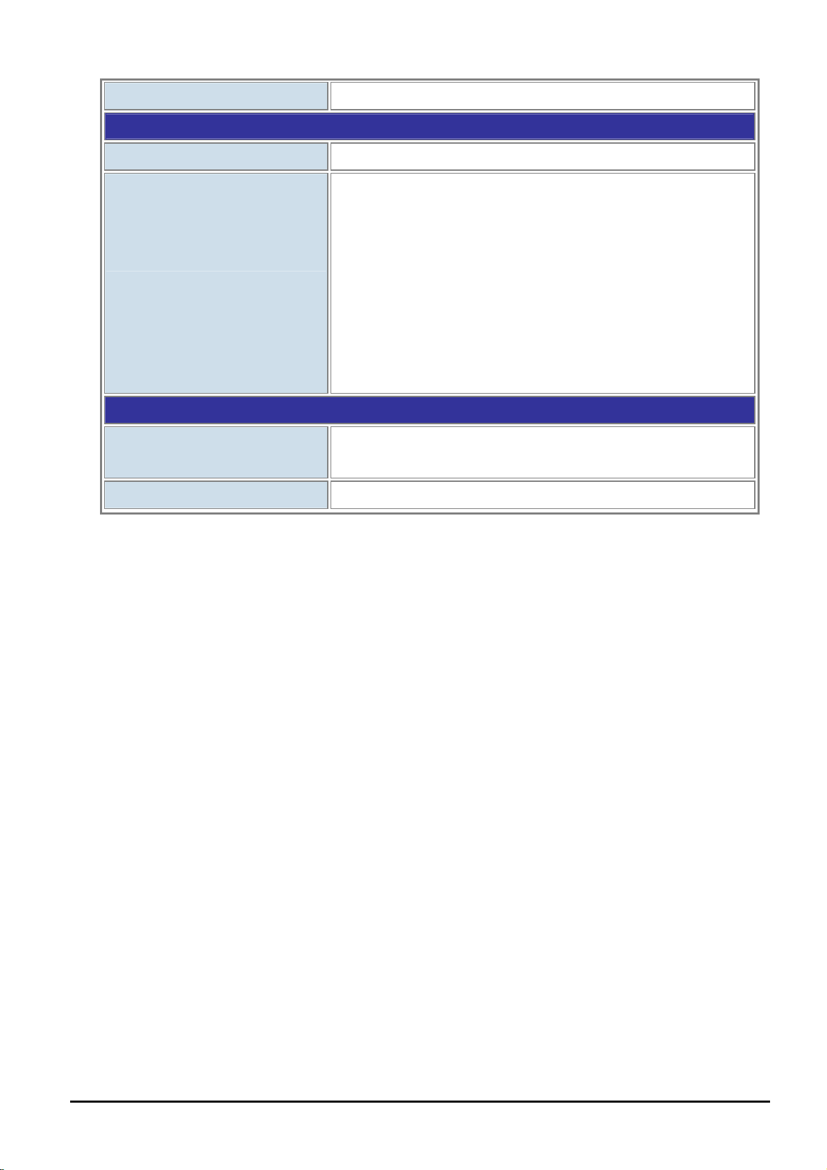
Smart Functions
System Configuration
Port Configuration
Bandwidth Control
Broadcast Storm Control
Port Statistics
VLAN
Spanning Tree Protocol
Port Trunking
Port Mirroring
QoS
Web interface, SNMP v1
Port speed duplex mode selection. Flow control disable / enable. Port
disable / enable. Port description on each port
Yes, 1 / 2 / 4 / 8 / 16 / 32 / 64Mbps
Yes, 5% / 10% / 25% / 50% / disable
Display each port’s detailed Ethernet traffic counter information
26 port-based VLAN groups / 32 IEEE 802.1Q VLAN groups / MTU VLAN
STP, IEEE 802.1d (Spanning Tree Protocol)
RSTP, IEEE 802.1w (Rapid Spanning Tree Protocol)
Supports 2 groups of 4-port 10/ 100Base-TX trunk support, up to 800Mbps
bandwidth per trunk
Supports 1 group of 2-port 10/100/1000Mbps trunk support, up to
2000Mbps bandwidth per trunk
Port mirroring allows monitoring of the traffic across any port in real time
Allows to assign low / high priority on each port.
First-In-First-Out, All-High-before-Low, Weight-Round-Robin QoS policy.
MAC Address / TCP & UDP Filter
- 9 -
Yes
User’s Manual of FGSW-2620CS
IGMP Snooping v1 / v2
Standards Conformance
Regulation Compliance
Standards Compliance
Environment
Temperature
Operating Humidity
Allows to disable or enable.
FCC Part 15 Class A, CE
IEEE 802.3 (Ethernet)
IEEE 802.3u (Fast Ethernet)
IEEE 802.3ab (Gigabit Ethernet)
IEEE 802.3z (Gigabit Ethernet)
IEEE 802.3x (Full-duplex flow control)
IEEE 802.1Q VLAN
IEEE 802.1p QoS
IEEE 802.1D (Spanning Tree Protocol)
IEEE 802.1w (Rapid Spanning Tree Protocol)
Operating: 0~50 degrees C
Storage: -10~70 degrees C
5% to 90%, Storage: 5% to 90% (non-condensing)
- 10 -
User’s Manual of FGSW-2620CS
2. HARDWARE DESCRIPTION
This product provides three different running speeds – 10Mbps, 100Mbps and 1000Mbps in the same Web Smart Switch
and automatically distinguishes the speed of incoming connection.
This section describes the hardware features of Web Smart Switch. For easier management and control of the Web Smart
Switch, familiarize yourself with its display indicators, and ports. Front panel illustrations in this chapter display the unit LED
indicators. Before connecting any network device to the Web Smart Switch, read this chapter carefully.
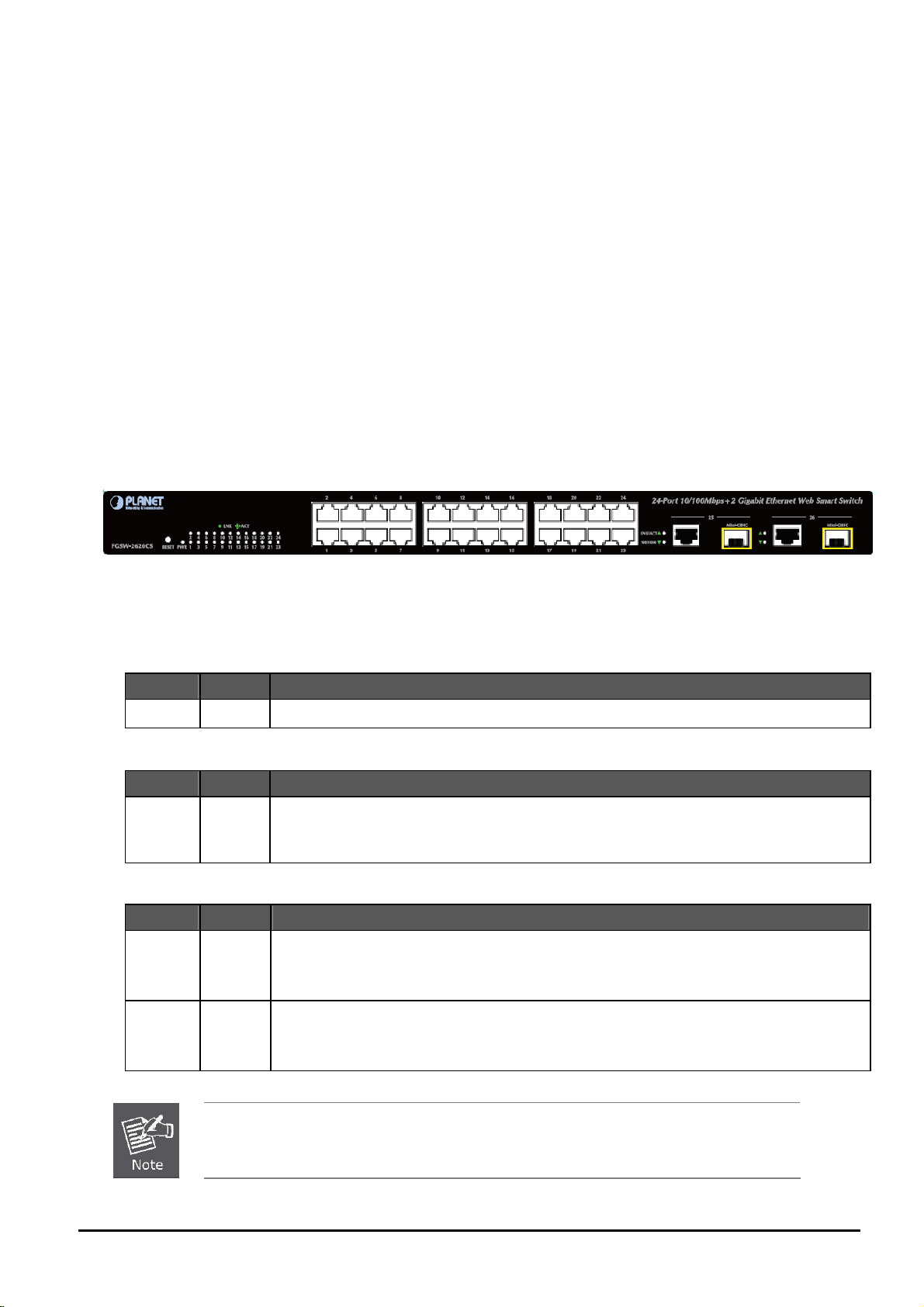
2.1 Front Panel
The front panel of the Web Smart Ethernet Switch consists of 24x auto-sensing 10/100Mbps Ethernet RJ-45 ports and 2
Gigabit TP/SFP combo ports, which can either be 1000Base-T for 10/100/1000Mbps or 1000Base-SX/LX through SFP
(Small Factor Pluggable) interface.
The LED Indicators are also located on the front panel of the Web Smart Switch.
Figure 2-1: FGSW-2620CS Switch Front Panel
2.1.1 LED Indicators
System
LED Color Function
PWR Green Lights to indicate that the Switch has power.
Per 10/100Mbp s port
LED Color Function
LNK/ACT Green
Per 10/100/100 -T port / SFP interfaces
LED Color Function
LNK/ACT Green
100/1000 Green
Lights to indicate the link through that port is established at 10/100Mbps full duplex mode.
Blinks slowly to indicate the link through that port is established at 10/100Mbps half duple
Blinks fast to indicate that the sw
0Base
Lights to indicate the link through that port is established at 10/100/1000Mbps full duplex mode.
Blinks slowly to indicate the link through that port is established at 10/100Mbps half duple
Blinks fast to indicate that the switch is actively sending o
Steadily Lights to indicate the port is run at 1000Mbp
Blinks Slowly to indicate the port is run at 100Mbps
Off: indicates that the port is operating at 10Mbps.
itch is actively sending or receiving data over that port.
x mode.
x mode.
r receiving data over that port.
s.
1. Press the RESET button once and the Web Smart Switch will reboot automatically.
2. Press the RESET button for 5 seconds and the Web Smart Switch will return to the factory
default mode; the entire configuration will be erased.
- 11 -

User’s Manual of FGSW-2620CS
2.2 Rear Panel
The rear panel of the Web Smart Switch indicates an AC inlet power socket, which accepts input power from 100 to
240VAC, 50-60Hz, 0.5A.
Figure 2-2: FGSW-2620CS Switch Rear Panel
Power Notice:
1. The device is a power-required device, meaning it will not work till it is powered. If your networks should be active all the
time, please consider using UPS (Uninterrupted Power Supply) for your device. It will prevent you from network data
loss or network downtime.
2. In some area, installing a surge suppression device may also help to protect your Web Smart Switch from being
damaged by unregulated surge or current to the Web Smart Switch.
2.3 Hardware Installation
This part describes how to install your Web Smart Switch and make connections to the Switch. Please read the following
topics and perform the procedures accordingly. To install your Web Smart Switch on a desktop or shelf, simply complete
the following steps.
2.3.1 Desktop Installation
To install Web Smart Switch on a desktop or shelf, simply complete the following steps:
Step 1: Attach the rubber feet to the recessed areas on the bottom of the Web Smart Switch.
Step 2: Place the Web Smart Switch on a desktop or shelf near an AC power source.
Step 3: Keep enough ventilation space between the Web Smart Switch and the surrounding objects.
Step 4: Connect your Switch to network devices.
A. Connect one end of a standard network cable to the 10/100 RJ-45 ports on the front of the Web Smart Switch.
B. Connect the other end of the cable to the network devices such as printer servers, workstations or routers.
When choosing a location, please keep in mind the environmental restrictions discussed in
Chapter 1, Section 4 under Specifications.
Connection to the Web Smart Switch requires UTP Category 5 network cabling with RJ-45 tips.
For more information, please see the Cabling Specifications in Appendix A.
- 12 -
User’s Manual of FGSW-2620CS
Step 5: Supply power to the Web Smart Switch.
A. Connect one end of the power cable to the Web Smart Switch.
B. Connect the power plug of the power cable to a standard wall outlet and then power on the Web Smart Switch.
When the Web Smart Switch receives power, the Power LED should remain solid Green.
2.3.2 Rack Mounting
To install the Web Smart Switch in a 19-inch standard rack, follow the instructions described below.
Step 1: Place your Web Smart Switch on a hard flat surface, with the front panel positioned towards your front side.
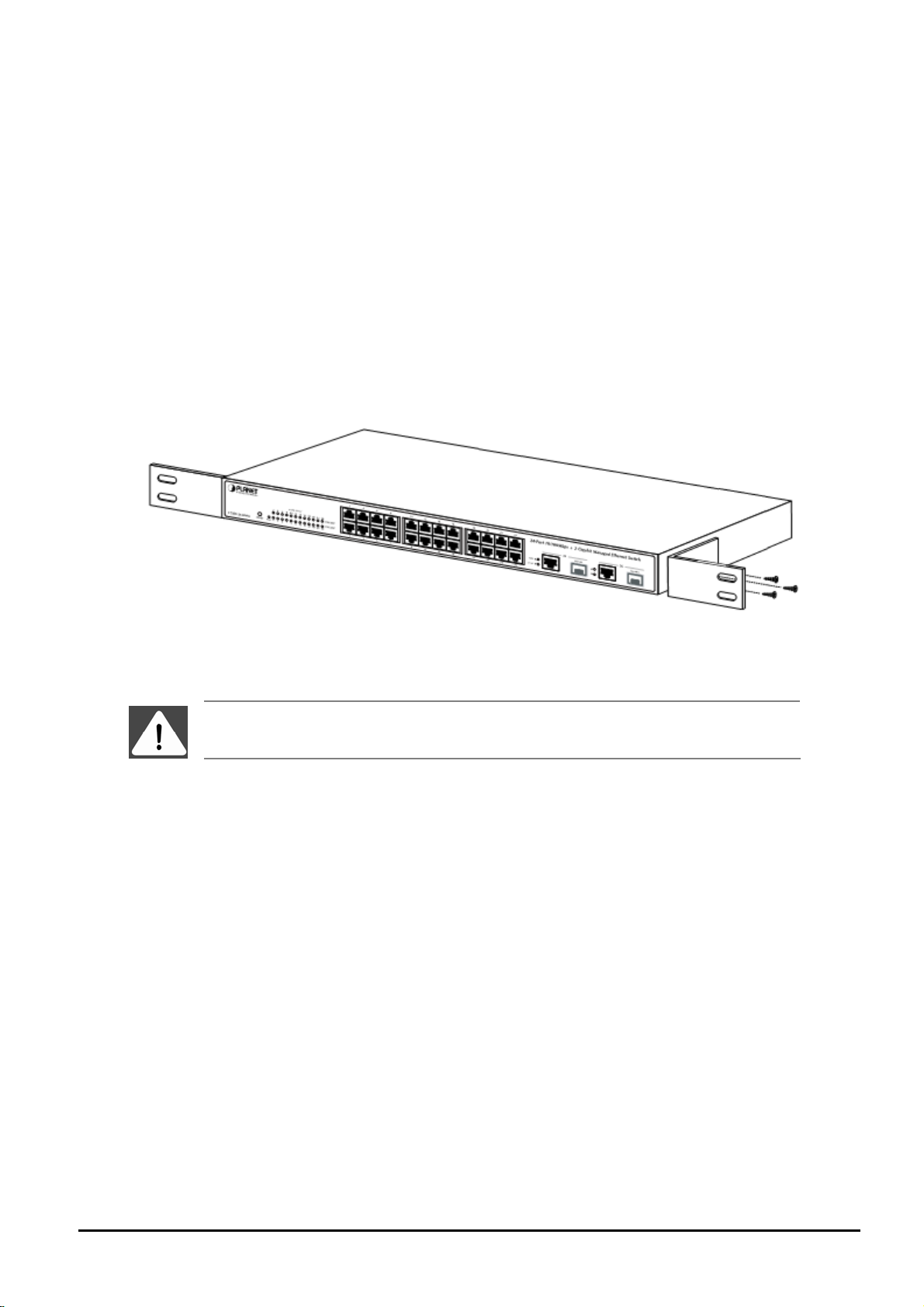
Step 2: Attach a rack-mount bracket to each side of the Web Smart Switch with supplied screws attached to the package.
Figure 2-3 shows how to attach brackets to one side of the Web Smart Switch.
Figure 2-3 Attaching the brackets to the Web Smart Switch
You must use the screws supplied with the mounting brackets. Damage caused to the parts by
using incorrect screws would invalidate your warranty.
Step 3: Secure the brackets tightly.
Step 4: Follow the same steps to attach the second bracket to the opposite side.
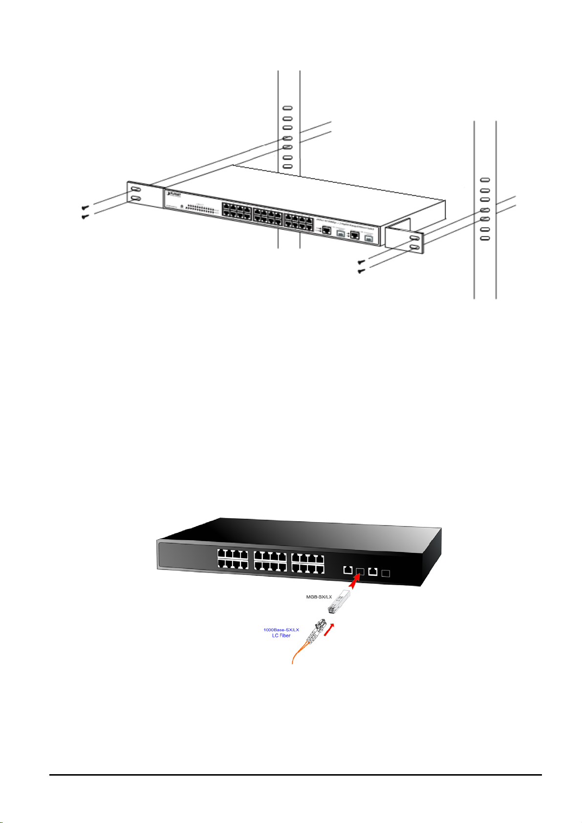
Step 5: After the brackets are attached to the Web Smart Switch, use suitable screws to securely attach the brackets to the
rack, as shown in Figure 2-4.
- 13 -
User’s Manual of FGSW-2620CS
Figure 2-4 Mounting the Web Smart Switch in a Rack
Step 6: Proceed with Steps 4 and 5 under Section 2.3.1 Desktop Installation to connect the network cabling and supply
power to your Web Smart Switch.
2.3.3 Installing the SFP transceiver
The sections describe how to insert an SFP transceiver into an SFP slot.
The SFP transceivers are hot-pluggable and hot-swappable. You can plug in and out the transceiver to/from any SFP port
without having to power down the Web Smart Switch as the Figure 2-5 appears.
Figure 2-5 Inserting the SFP transceiver
- 14 -

User’s Manual of FGSW-2620CS
Approved PLANET SFP Transceivers
PLANET Web Smart Switch supports both single mode and multi mode SFP transceivers. The following list of approved
PLANET SFP transceivers is correct at the time of publication:
■MGB-SX SFP (1000Base-SX SFP transceiver )
■MGB-LX SFP (1000Base-LX SFP transceiver )
It is recommended to use PLANET SFP transceiver on the Web Smart Switch. If you insert an
SFP transceiver that is not supported, the Web Smart Switch will not recognize it.
Before connecting the other switches, workstation or Media Converter.
1. Make sure both sides of the SFP transceiver are with the same media type, for example: 1000Base-SX to
1000Base-SX, 1000Base-LX to 1000Base-LX.
2. Check the fiber-optic cable type that matches the SFP transceiver model.
To connect to 1000Base-SX SFP transceiver, use the multi-mode fiber cable- with one side being male duplex
LC connector type.
To connect to 1000Base-LX SFP transceiver, use the single-mode fiber cable-with one side bein g male du-
plex LC connector type.
Connect the fiber cable
1. Insert the duplex LC connector on the network cable into the SFP transceiver.
2. Connect the other end of the cable to a device – switches with SFP installed, fiber NIC on a workstation or a Media
Converter..
3. Check the LNK/ACT LED of the SFP slot on the front of the Web Smart Switch. Ensure that the SFP transceiver is
operating correctly.
4. Check the Link mode of the SFP port if the link fails. Functioning with some fiber-NICs or Media Converters and setting
the Link mode to “1000 Force” are needed.
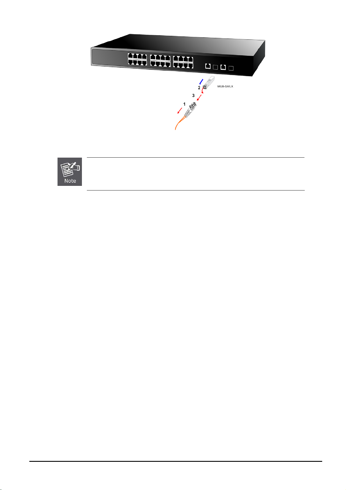
Remove the transceiver module
1. Make sure there is no network activity by consulting or checking with the network administrator. Or through the
management interface of the switch/converter (if available) to disable the port in advance.
2. Remove the Fiber Optic Cable gently.
3. Turn the handle of the MGB module to a horizontal position.
4. Pull out the module gently through the lever..
- 15 -
User’s Manual of FGSW-2620CS
Figure 2-6 Removing the SFP transceiver
Never pull out the module without pulling the lever or the push bolt of the module. Directly
pulling out the module with force could damage the module and SFP module slot of the Web
Smart Switch.
- 16 -
User’s Manual of FGSW-2620CS
3. SWITCH MANAGEMENT
This chapter describes how to manage the Web Smart Switch. Topics include:
- Overview
- Management Method
- Logging on to the Web Smart Switch
3.1 Overview
The Web Smart Switch provides a user-friendly, Web interface. With this interface, you can perform various switch configuration and management activities, including:
Please refer to the following Chapter 4 for the details.
3.2 Management Method
User can manage the Web Smart Switch by Web Management via a network connection.
3.2.1 Web Management
PLANET
host with Web browser, such as Microsoft Internet Explorer, Netscape Navigator or Mozilla Firefox.
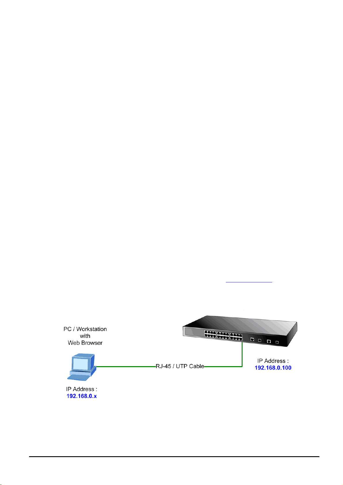
The following shows how to start up the Web Management of the Switch. Please note the Switch is configured through an
Ethernet connection. Make sure the manager PC must be set on the same IP subnet address; for example, the default IP
address of the Switch is 192.168.0.100 (the factory-default IP address), then the manager PC should be set at 192.168.0.x
(where x is a number between 1 and 254, except 100), and the default subnet mask is 255.255.255.0.
Use Internet Explorer 7.0 or the above Web browser and enter default IP address http://192.168.0.100
After entering the user name and password (default user name and password are “admin”) in login screen
FGSW-2620CS provides a built-in browser interface. You can manage the Switch remotely by havin g a remote
3.2.2 PLANET Smart Discovery Utility
To easily list the FGSW-2620CS in your Ethernet environment, Planet Smart Discovery Utility from user’s manual
CD-ROM is an ideal solution.
- 17 -
The following install instructions guide you to running Planet Smart Discovery Utility.
1. Insert Planet Smart Discovery Utility in administrator PC.
2. Run this utility and the following screen appears.
User’s Manual of FGSW-2620CS
Figure 3-1 Planet Smart Discovery Utility Screen
If there are two LAN cards or above in the same administrator PC, choose a different LAN card by
using the “Select Adapter” tool.
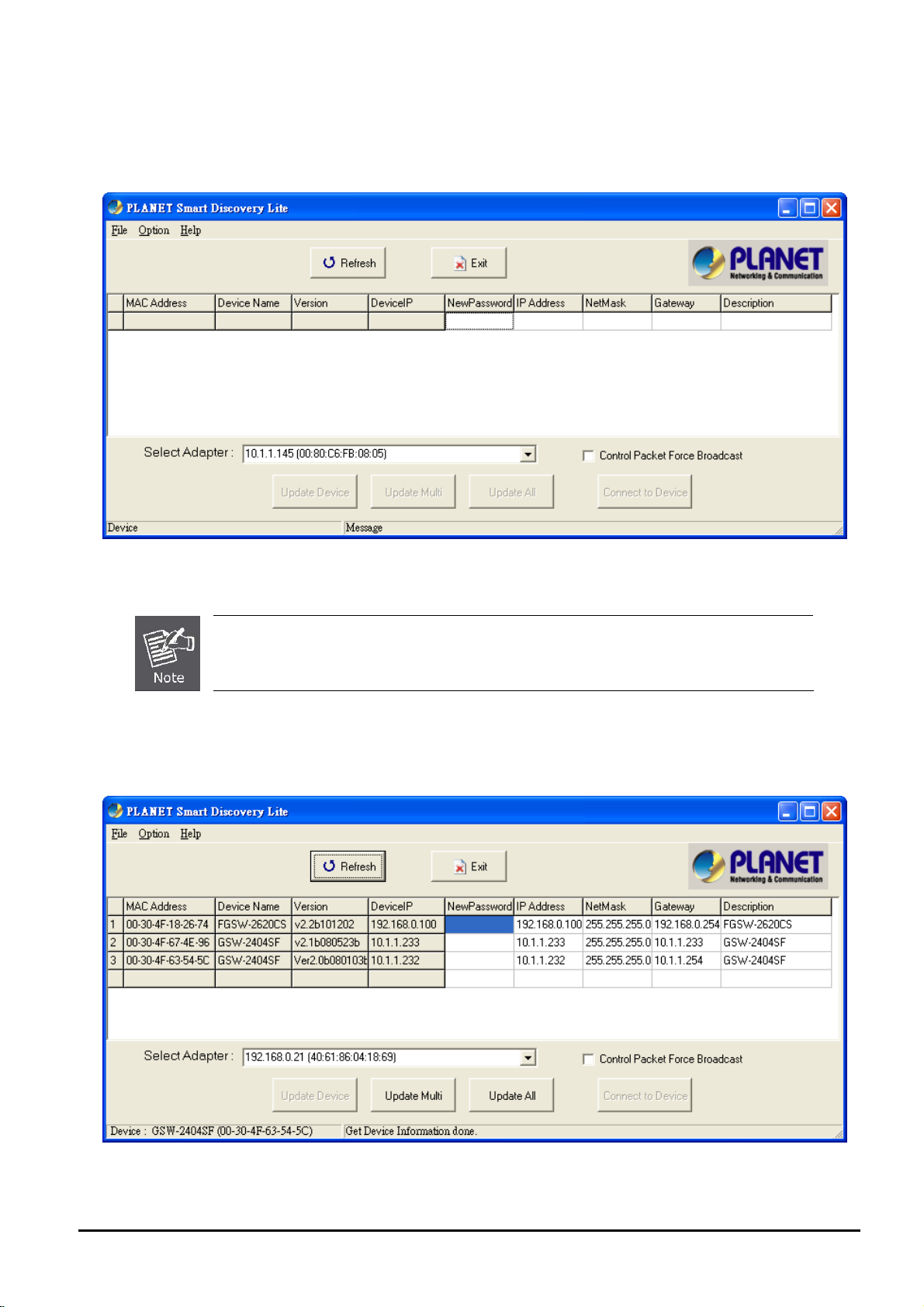
3. Press “Refresh” button for the currently connected devices in the discovery list as the screen is shown as follo ws.
Figure 3-2 Planet Smart Discovery Utility Screen
- 18 -
User’s Manual of FGSW-2620CS
This utility shows all the necessary information from the devices, such as MAC Address, Device Name, firmware version,
and Device IP Subnet address. It also can assign new password, IP Subnet address and description to the devices.
3. After the setup is completed, press “Update Device”, “Update Multi” or “Update All” button to take effect. The fea-
tures of the 3 buttons are shown below:
Update Device: use current setting on one single device.
Update Multi: use current setting on multi-devices.
Update All: use current setting on the whole devices in the list.
The same functions mentioned above also can be found in “Option” tools bar.
4. To click the “Control Packet Force Broadcast” function, it can allow assigning new setting value to the Web Smart
Switch under different IP subnet addresses.
6. Press “Connect to Device” button and then the Web login screen appears in Figure 3-3.
7. Press “Exit” button to shut down Planet Smart Discovery Utility.
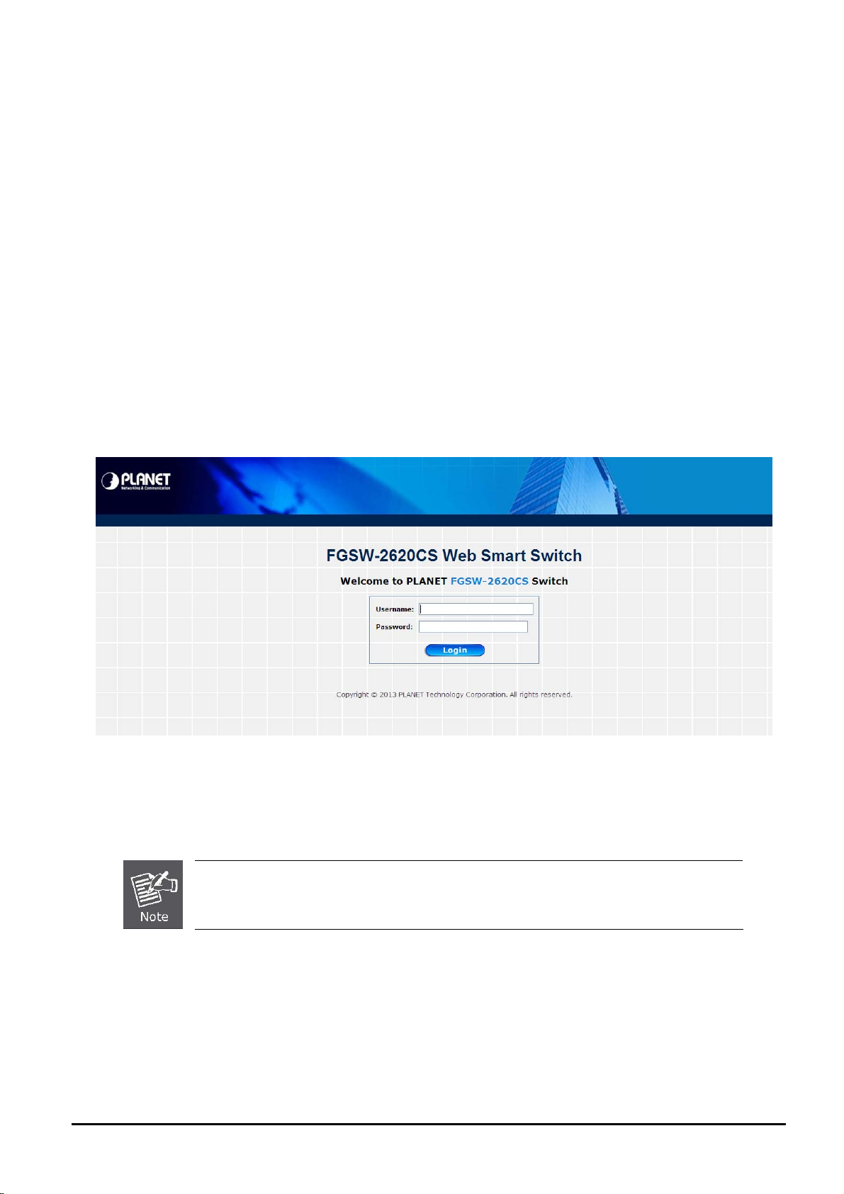
3.3 Logging on to the FGSW-2620CS
When you log on to the Web Smart Switch Web interface for the first time, a sign-on string appears and you are prompted
for a Web login user name and password.
Figure 3-3 Web Smart Switch Web Login Screen
he factory default login user name and password are admin.
T
For security reason, please change and memorize the new password after this first setup.
- 19 -
User’s Manual of FGSW-2620CS
a
4. WEB MANAGEMENT
To modify your PC’s IP domain to the same with Web Smart Switch, use the default IP address (192.168.0.100) to remotely configure Web Smart Switch through the Web interface.
4.1 Login in to the Switch
To access the Web-browser interface, you must first enter the user name and password. The default user name and
password are "admin”. The following screen will appear on the Web browser program:
Figure 4-1 Web Login Screen
Aft
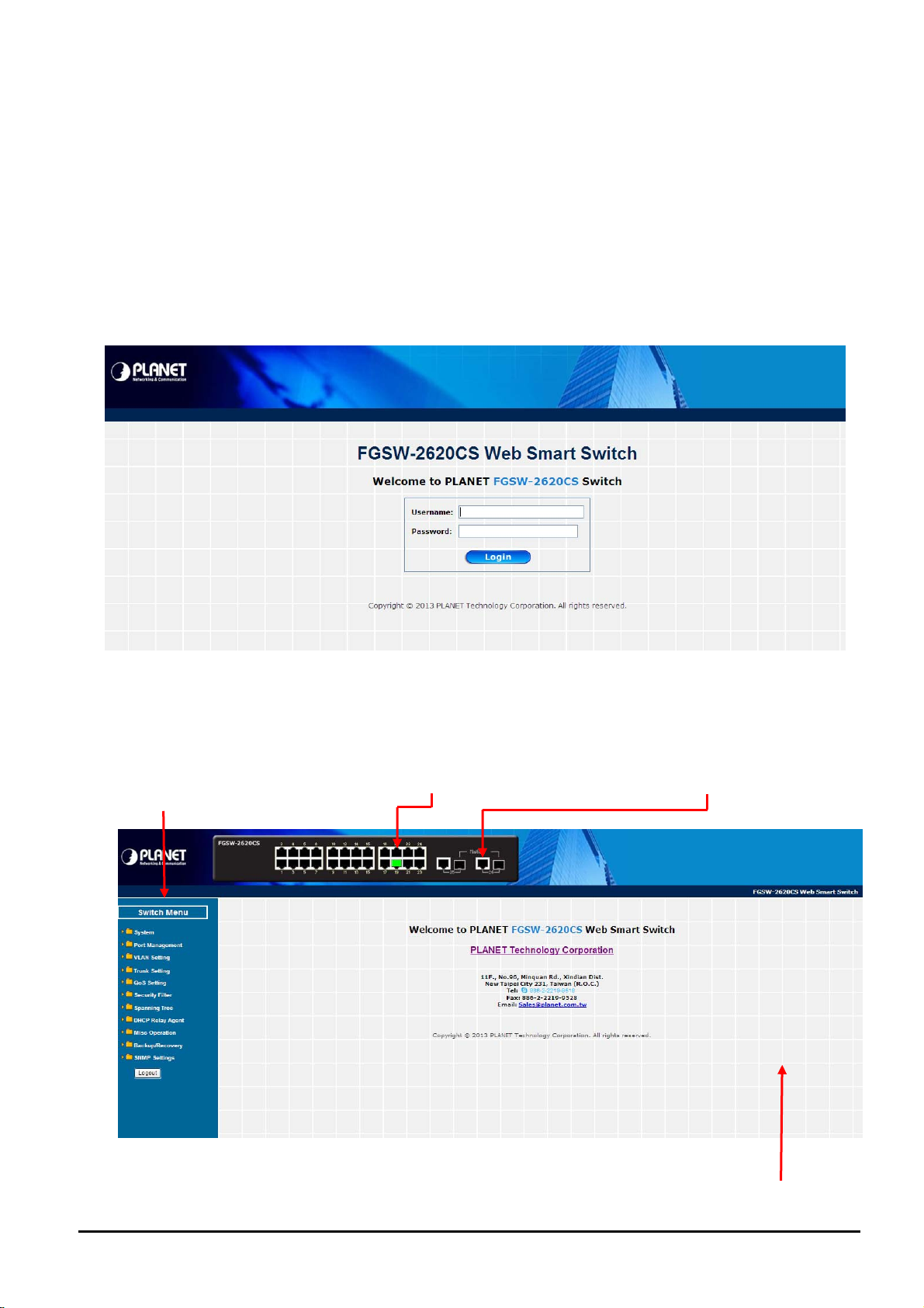
er the user name and password are entered, you will see the Web Main Menu screen.
T
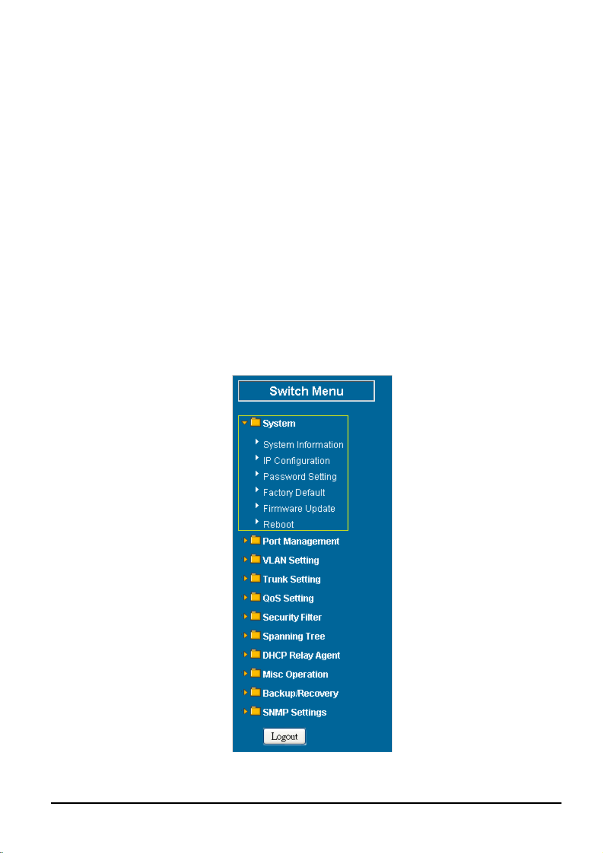
he Switch Menu provides seven majo in Figu
Main Functions Menu
r management functions as the screen re 4-2 appears.
Fast Ethernet Port Link Status Gigabit Port Link Status
Figure 4-2 Web Main Menu Screen
The seven items are described below:
- 20 -
in Screen
M
User’s Manual of FGSW-2620CS
◆ System: Provides System configuration of Web Smart Switch. Explained in section 4.2.
◆ Port Management: Provides Port Management configuration of Web Smart Switch. Explained in section 4.3.
◆ VLAN Setting: Provides VLAN Setting configuration of Web Smart Switch. Explained in section 4.4.
◆ Trunk Setting: Provides Trunk Setting configuration of Web Smart Switch. Explained in section 4.
◆ QoS Setting: Provide sQoS Setting configuration of Web Smart Switch. Explained in section 4.6.
◆ Security Filter: Provides Security Filter configuration of Web Smart Switch. Explained in section 4.7.
◆ Spanning Tree: Provides Spanning Tree configuration of Web Smart Switch. Explained in section 4.8.
◆ DHCP Relay Agent: Provides DHCP Relay Agent configuration of Web Smart Switch. Explained in section
◆ Misc Operation: Provides Misc Operation configuration of Web Smart Switch. Explained in section 4.10.
◆ Backup/Recovery: Provides Backup/Recovery configuration of Web Smart Switch. Explained in section 4.11.
◆ SNMP Settings: Provides SNMP Settings configuration of Web Smart Switch. Explai
◆ Logout: Provides Logout function of Web Smart Switch. Explained in section 4.13.
ned in section 4.12.
5.
4.9.
4.2 System
This section provides System Information, IP Configuration, Pass
Reboot functions of Web Sma
of Web Smart Switch.
rt Switch as the screen in Figure 4-3 appears and Table 4-1 describes the System object
word Setting, Factory Default, Firmware Update and
Figure 4-3 System Web Page Screen
- 21 -
Object Description
User’s Manual of FGSW-2620CS
System Information
IP Configuration
Password Setting
Factory Default
Firmware Update
Reboot
Displays the MAC address, Hardware Version, and Software Version, Device Description.
Explained in section 4.2.1.
Allows to change the IP subnet address of Web Smart Switch. Explained in section 4.2.2.
Allows to change the user name and password of Web Smart Switch. Explained in section
4.2.3.
Allows to reset the Web Smart Switch to factory default mode. Explained in section 4.2.4.
Allows to proceed firmware upgrade process of Web Smart Switch. Explained in section 4.2.5.
Allows to reboot the Web Smart Switch. Explained in section 4.2.6.
Table 4-1 Descriptions of the System Web Page Screen Objects
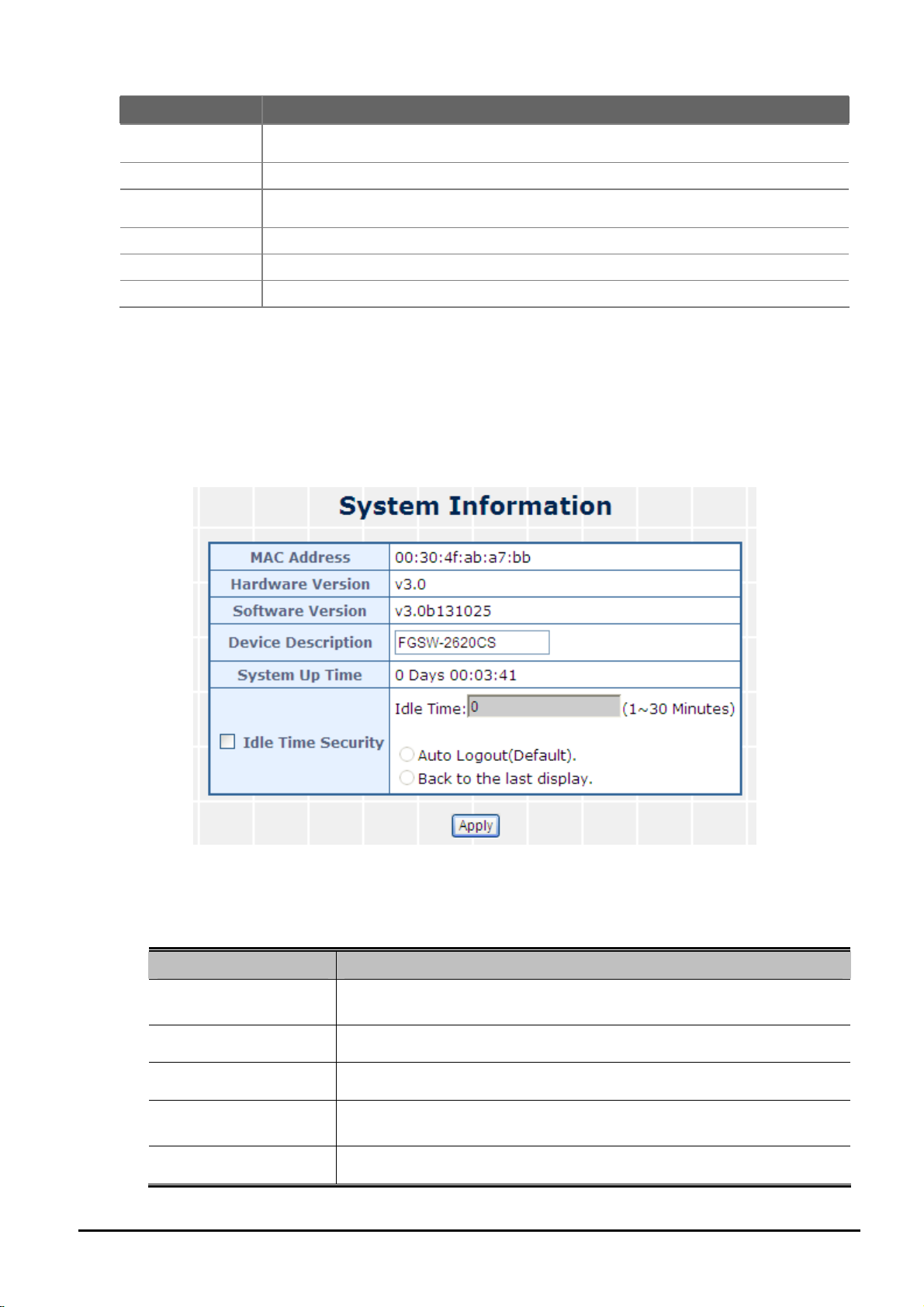
4.2.1 System Information
his section displays the MAC address, Hardware Version and Software Version and allows to define the device de-
T
scription. Press “Apply” button to take effect as the screen in Figure 4-4 appears.
Figure 4-4 System Information Web Page Screen
The page includes the following fields:
Object Description
MAC Address
Displays the unique hardware address assigned by manufacturer (default).
Hardware Version
Software Version
Device Description
Displays the current hardware version.
The software version of the switch.
Describes the Managed Switch. Up to 15 characters are allowed for the
Device Description.
System Up Time
- 22 -
The period of time the device has been operational.
User’s Manual of FGSW-2620CS
Idle Time Security
Table 4-2 Descriptions of the System Information Web Page Screen Objects
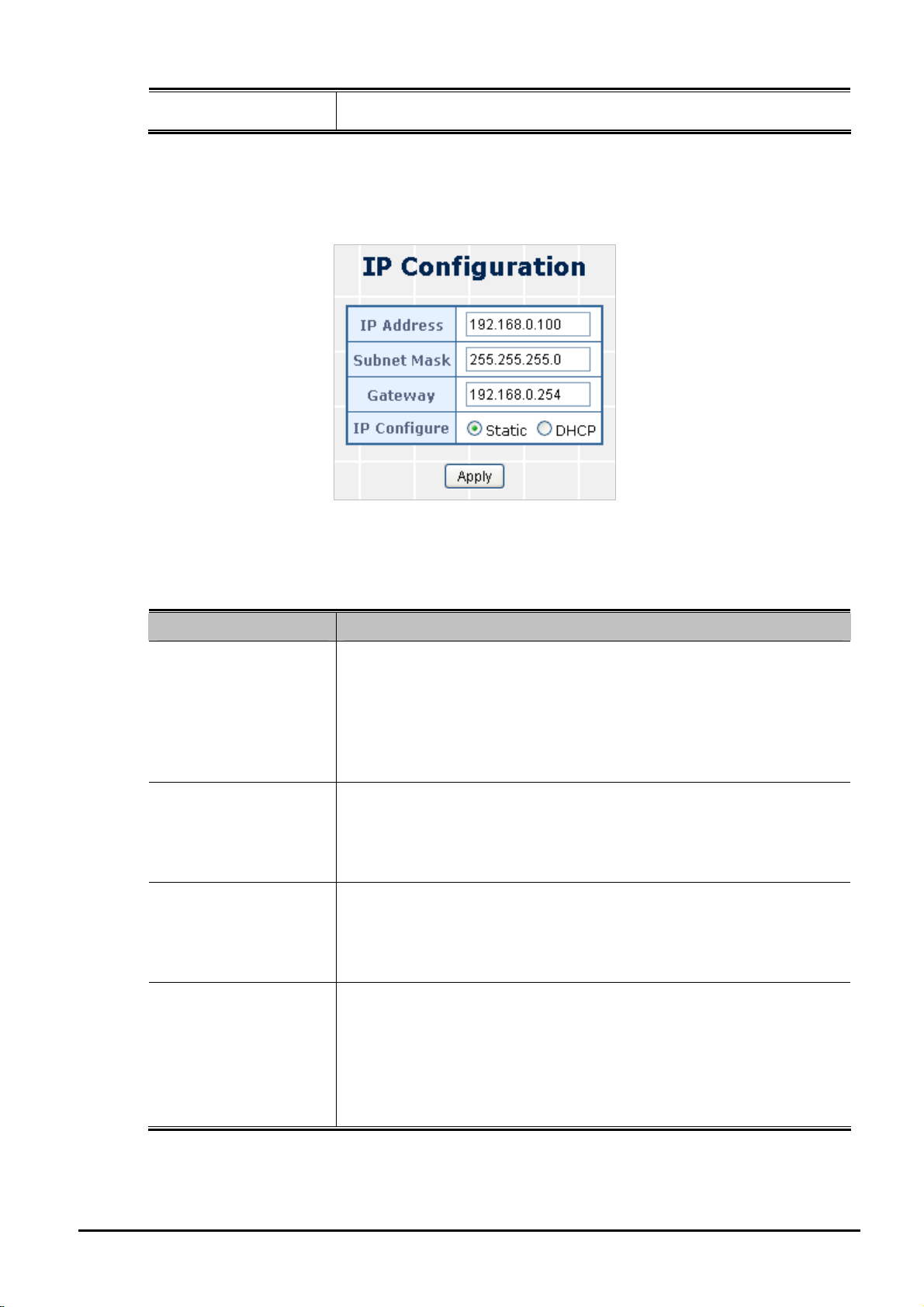
4.2.2 IP Configuration
This section provides change in the IP Address, Subnet Mask and Gateway as the screen in Figure 4-5 appears.
Set idle time and behavior.
Figure 4-5 IP Configuration Web Page Screen
The page includes the following fields:
Object Description
Assign the IP address that the network is using.
If DHCP client function is enabled, this switch is configured as a DHCP
IP Address
client. The network DHCP server will assign the IP address to the switch
and display it in this column.
The default IP is 192.168.0.100 or the user has to assign an IP address
manually when DHCP Client is disabled.
Assign the subnet mask to the IP address.
Subnet Mask
If DHCP client function is disabled, the user has to assign the subnet
mask in this column field.
The default subnet mask is 255.255.255.0.
Assign the network gateway for the switch.
Gateway
If DHCP client function is disabled, the user has to assign the gateway in
this column field.
The default gateway is 192.168.0.254.
Select static IP address or DHCP client function
When DHCP function is enabled, the Web Smart Switch will be assigned
an IP address from the network DHCP server. The default IP address will
IP Configure
be replaced by the assigned IP address on DHCP server. After the user
clicks Apply, a popup dialog shows up to inform the user that when the
DHCP client is enabled, the current IP will lose and user should find the
new IP on the DHCP server.
Table 4-3 Descriptions of the IP Configuration Web Page Screen Objects
4.2.3 Password Setting
This section provides change in the user name and password as the screen in Figure 4-6 appears.
- 23 -
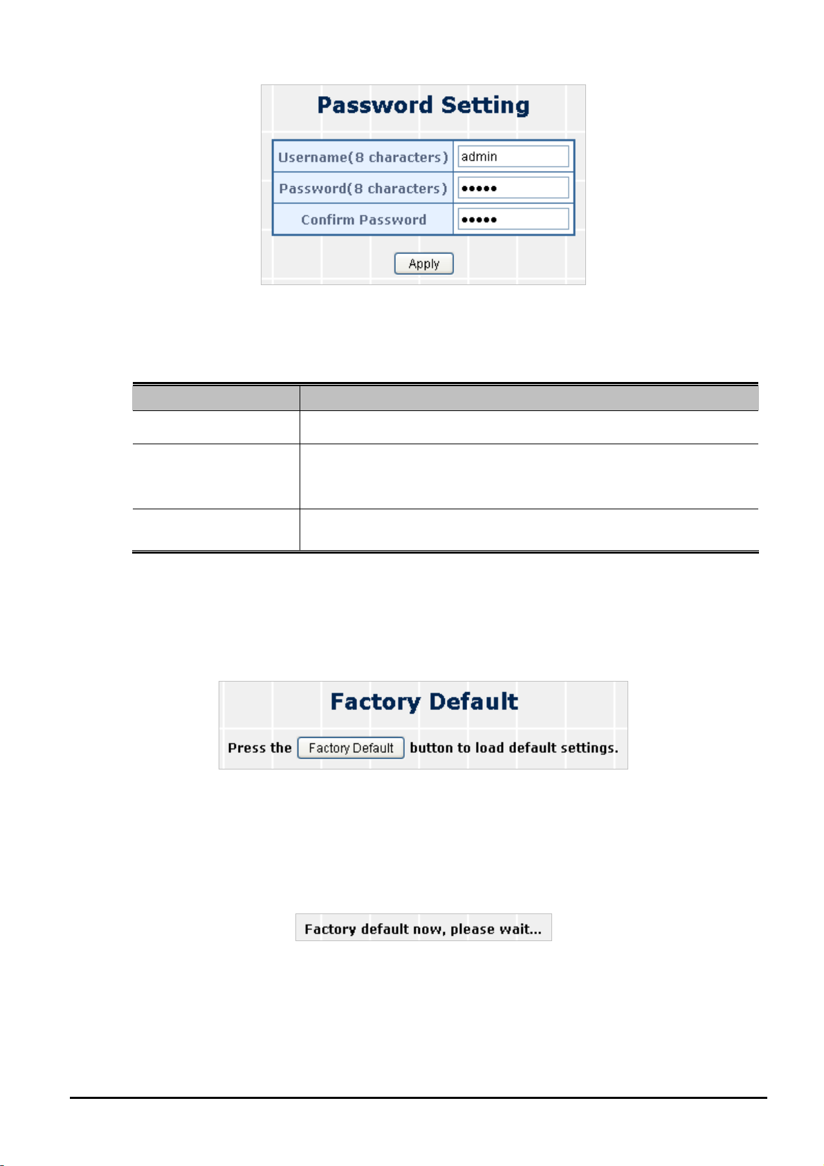
Figure 4-6 Password Setting Web Page Screen
The page includes the following fields:
Object Description
User’s Manual of FGSW-2620CS
User Name
Password
Displays the user name.
Specifies the new password. The password is not displayed. As it enters
a “” corresponding to each character is displayed in the field.
(The maximum length is 8 characters)
Confirm Password
This confirms the new password. The password entered into this field
must be exactly the same as the password entered in the Password field.
Table 4-4 Descriptions of the Password Setting Web Page Screen Objects
4.2.4 Factory Default
This section shows how to reset the Web Smart Switch to factory default mode as the screen in Figure 4-7 appears.
Figure 4-7 Factory Default Web Page Screen
Press “Factory Default” button to take effect. The following screen in Figure 4-8 appears and then another Web page
login screen with default setting will show. After the default user name and password are filled out, the Web Smart Switch
management will continue its function.
Figure 4-8 Factory Default Web Page Screen
4.2.5 Firmware Update
This section provides the firmware upgrade of the Web Smart Switch as the screen in Figure 4-9 appears.
- 24 -

User’s Manual of FGSW-2620CS
Figure 4-9 Firmware Update Web Page Screen
Press “Update” button for start the firmware upgrade process, the screen in Figure 4-10 & 4-11 appears.
Figure 4-10 Firmware Update Web Page Screen
Figure 4-11 Firmware Update Web Page Screen
Press “Browser” button to find the firmware location on administrator PC as the screen in Figure 4-12 appears.
Figure 4-12 Firmware Update Web Page Screen
After locating the firmware on administrator PC, press “Update” button to start the firmware upgrade process as the
screen in Figure 4-13 appears.
Figure 4-13 Firmware Update Web Page Screen
When firmware upgrade process is completed, then the following screen appears. Please press continue button and
the page will turn to the login page.to enable to use the latest firmware of the Web Smart Switch.
- 25 -
 Loading...