


 Loading...
User's Manual
ISW-504PS / ISW-514PS
ISW-514PS15 / ISW-514PSF
5-Port 10/100Mbps with
4-Port PoE Web Smart Industrial Ethernet Switch
-1-

User’s Manual
Trademarks
Copyright © PLANET Technology Corp. 2010.
Contents subject to revise without prior notice.
PLANET is a registered trademark of PLANET Technology Corp. All other trademarks belong to their respective owners.
Disclaimer
PLANET Technology does not warrant that the hardware will work properly in all environments and applications, and makes no warranty and representation, either implied or expressed, with respect to the quality, performance, merchantability, or fitness for a particular purpose.
PLANET has made every effort to ensure that this User’s Manual is accurate; PLANET disclaims liability for any inaccuracies or omissions that may have occurred.
Information in this User’s Manual is subject to change without notice and does not represent a commitment on the part of PLANET. PLANET assumes no responsibility for any inaccuracies that may be contained in this User’s Manual. PLANET makes no commitment to update or keep current the information in this User’s Manual, and reserves the right to make improvements to this User’s Manual and/or to the products described in this User’s Manual, at any time without notice.
If you find information in this manual that is incorrect, misleading, or incomplete, we would appreciate your comments and suggestions.
FCC Warning
This equipment has been tested and found to comply with the limits for a Class A digital device, pursuant to Part 15 of the FCC Rules. These limits are designed to provide reasonable protection against harmful interference when the equipment is operated in a commercial environment. This equipment generates, uses, and can radiate radio frequency energy and, if not installed and used in accordance with the Instruction manual, may cause harmful interference to radio communications. Operation of this equipment in a residential area is likely to cause harmful interference in which case the user will be required to correct the interference at his own expense.
CE Mark Warning
This is a Class A product. In a domestic environment, this product may cause radio interference, in which case the user may be required to take adequate measures.
Energy Saving Note of the Device
This power required device does not support Standby mode operation.
For energy saving, please remove the power cable to disconnect the device from the power circuit.
Without removing power cable, the device will still consuming power from the power source. In the view of Saving the Energy and reduce the unnecessary power consuming, it is strongly suggested to remove the power connection for the device if this device is not intended to be active.
-2 -

User’s Manual
WEEE Warning
To avoid the potential effects on the environment and human health as a result of the presence of hazardous substances in electrical and electronic equipment, end users of electrical and electronic equipment should understand the meaning of the crossed-out wheeled bin symbol. Do not dispose of WEEE as unsorted municipal waste and have to collect such WEEE separately.
Revision
PLANET 5-Port 10/100Mbps with 4-Port PoE Web Smart Industrial Ethernet Switch User's Manual FOR MODELS: ISW-504PS / ISW-514PS / ISW-514PS15 / ISW-514PSF
REVISION: 1.0 (JULY.2010)
Part No.: EM-ISW-5xxPS Series_v1.0 (2080-AH0240-000)
-3 -
|
User’s Manual |
|
TABLE OF CONTENTS |
|
|
1. INTRODUCTION ............................................................................................................ |
7 |
|
1.1 PACKAGE CONTENTS ................................................................................................................................. |
7 |
|
1.2 PRODUCT DESCRIPTION ............................................................................................................................. |
7 |
|
1.3 FEATURES ................................................................................................................................................. |
8 |
|
1.4 SPECIFICATION .......................................................................................................................................... |
9 |
|
1.5 PRODUCT APPLICATION ........................................................................................................................... |
11 |
|
2. INSTALLATION............................................................................................................ |
12 |
|
2.1 HARDWARE DESCRIPTION ........................................................................................................................ |
12 |
|
2.1.1 Physical Dimension......................................................................................................................... |
12 |
|
2.1.2 Front Panel ..................................................................................................................................... |
12 |
|
2.1.2 Front Panel ..................................................................................................................................... |
13 |
|
2.1.3 LED Indicators ................................................................................................................................ |
14 |
|
2.1.4 Switch Upper Panel ........................................................................................................................ |
15 |
|
2.2 INSTALL THE SWITCH ................................................................................................................................ |
16 |
|
2.2.1 Installation Steps............................................................................................................................. |
16 |
|
2.2.2 DIN-Rail Mounting........................................................................................................................... |
16 |
|
2.2.3 Wall Mount Plate Mounting............................................................................................................. |
19 |
|
2.3 WIRING THE POWER INPUTS ..................................................................................................................... |
19 |
|
2.4 WIRING THE FAULT ALARM CONTACT ....................................................................................................... |
20 |
|
2.5 CABLING ................................................................................................................................................. |
21 |
|
2.5.1 Installing the SFP transceiver (ISW-514PSF Only) ........................................................................ |
21 |
|
2.5.2 Remove the module........................................................................................................................ |
23 |
|
3 MANAGEMENT............................................................................................................. |
24 |
|
3.1 OVERVIEW ............................................................................................................................................... |
24 |
|
3.2 REQUIREMENTS ....................................................................................................................................... |
24 |
|
3.3 MANAGEMENT METHOD ........................................................................................................................... |
24 |
|
3.3.1 Web Management........................................................................................................................... |
24 |
|
3.3.2 PLANET Smart Discovery Utility..................................................................................................... |
27 |
|
4. WEB CONFIGURATION .............................................................................................. |
29 |
|
4.1 MAIN MENU ............................................................................................................................................. |
29 |
|
4.2 WEB PANEL............................................................................................................................................. |
30 |
|
4.3 SYSTEM................................................................................................................................................... |
31 |
|
|
|
|
-4 - |
|
|

|
User’s Manual |
4.3.1 System Information ......................................................................................................................... |
32 |
4.3.2 IP Configuration .............................................................................................................................. |
33 |
4.3.3 Password Setting ............................................................................................................................ |
34 |
4.3.4 Firmware Upgrade .......................................................................................................................... |
34 |
4.3.5 Configuration Setting ...................................................................................................................... |
38 |
4.3.6 Configuration Backup...................................................................................................................... |
40 |
4.3.7 Managed IP..................................................................................................................................... |
41 |
4.3.8 Fault Relay Alarm ........................................................................................................................... |
41 |
4.3.9 Alert Trap Configuration.................................................................................................................. |
42 |
4.3.10 System Reboot ............................................................................................................................. |
43 |
4.4 PORT MANAGEMENT ................................................................................................................................ |
44 |
4.4.1 Port Configuration ........................................................................................................................... |
44 |
4.4.2 Port Status ...................................................................................................................................... |
45 |
4.4.3 Port Security ................................................................................................................................... |
46 |
4.5 VLAN ..................................................................................................................................................... |
47 |
4.5.1 VLAN Group.................................................................................................................................... |
50 |
4.5.2 VLAN Per Port Setting .................................................................................................................... |
54 |
4.5.3 VLAN setting example: ................................................................................................................... |
56 |
4.6 QUALITY OF SERVICE ............................................................................................................................... |
63 |
4.6.1 802.1p Tag Priority Mode................................................................................................................ |
64 |
4.6.2 DSCP QoS Mode............................................................................................................................ |
66 |
4.6.3 Port-Based Priority Mode................................................................................................................ |
69 |
4.7 STORM CONTROL..................................................................................................................................... |
70 |
4.8 MISC CONFIGURATION ............................................................................................................................. |
71 |
4.9 POE CONFIGURATION .............................................................................................................................. |
73 |
4.9.1 Power over Ethernet Powered Device............................................................................................ |
73 |
4.9.2 Power Management:....................................................................................................................... |
73 |
4.10 LOGOUT ................................................................................................................................................ |
76 |
5. SWITCH OPERATION.................................................................................................. |
77 |
5.1 ADDRESS TABLE...................................................................................................................................... |
77 |
5.2 LEARNING................................................................................................................................................ |
77 |
5.3 FORWARDING & FILTERING ...................................................................................................................... |
77 |
5.4 STORE-AND-FORWARD ............................................................................................................................ |
77 |
5.5 AUTO-NEGOTIATION................................................................................................................................. |
78 |
|
-5 - |

|
User’s Manual |
6. POWER OVER ETHERNET OVERVIEW..................................................................... |
79 |
7. THE POE PROVISION PROCESS............................................................................... |
82 |
7.1 LINE DETECTION ...................................................................................................................................... |
82 |
7.2 CLASSIFICATION ...................................................................................................................................... |
82 |
7.3 START-UP................................................................................................................................................ |
83 |
7.4 OPERATION ............................................................................................................................................. |
83 |
7.5 POWER DISCONNECTION SCENARIOS........................................................................................................ |
83 |
8. TROUBLESHOOTING.................................................................................................. |
85 |
APPENDIX A NETWORKING CONNECTION ................................................................. |
86 |
A.1 DATA OUT POE SWITCH RJ-45 PORT PIN ASSIGNMENTS (PORT 1 TO PORT-4)....................................... |
86 |
A.2 10/100MBPS, 10/100BASE-TX ............................................................................................................... |
86 |
APPENDIX B .................................................................................................................... |
88 |
B.1 POWER OVER ETHERNET COMPATIBILITY TEST ......................................................................................... |
88 |
B.2 COMPATIBLE 100BASE-FX SFP TRANSCEIVER LIST (ISW-514PSF)........................................................ |
88 |
-6 -

User’s Manual
1. INTRODUCTION
The PLANET Layer 2 Web Smart Industrial PoE Switch series – ISW-5xxPS is multiple 10/100Mbps ports Ethernet Switched with 4-Port 802.3af PoE inject ability and robust layer 2 features; the description of these models as below:
ISW-504PS |
: |
5-Port 10/100Mbps with 4-PoE Industrial Web Smart Switch (-10~60 Degree C) |
|
: |
4+1 100FX Port (SC) with 4-PoE Industrial Web Smart Switch - 2km (-10~60 Degree C) |
ISW-514PS |
ISW-514PS15 : 4+1 100FX Port (SC) with 4-PoE Industrial Web Smart Switch - 15km (-10~60 Degree C)
ISW-514PSF : 4+1 100FX Port (LC) with 4-PoE Industrial Web Smart Switch (-10~60 Degree C)
1.1 Package Contents
Check the contents of your package for following parts:
Managed PoE Switch x1
User's Manual CD x1
Quick Installation Guide x1
DIN Rail Kit x 1
Wall Mount Kit x 1
If any of these pieces are missing or damaged, please contact your dealer immediately, if possible, retain the carton including the original packing material, and use them against to repack the product in case there is a need to return it to us for repair.
1.2 Product Description
The ISW-504PS / ISW-514PS series support MDI/ MDI-X convertible on 5 / 4-10/100Mbps ports, also provide PoE inject function on port 1, 2, 3 and 4, which is able to drive 4 IEEE 802.3af compliant powered devices. The dual speed ports use standard twisted-pair cabling and are ideal for SOHO or segmenting networks into small. Each 10/100Mbps port can supports up to 200Mbps of throughput in full-duplex mode, ISW-504PS / ISW-514PS series also provides a simple, cost-effective, and highly reliable network connection for data transmits. Furthermore, it is the ideal device for bridging among Ethernet, Fast Ethernet workgroups and networks.
With 4 PoE interfaces, the ISW-504PS / ISW-514PS series is ideal for small business and workgroups requiring to deploy the PoE for the wireless access points, IP-based surveillance camera or IP phones in any places easily, efficiently and cost effective.
The front panel of ISW-504PS / ISW-514PS series provides LEDs for easy recognition of the switch operation status and troubleshooting. These LED indicators display the power status for the system, LNK/ACT and speed for each10/100M port. Also the PoE in use LED indicates for PoE ports (port 1 to port 4).
With data and power over Ethernet from one unit, the ISW-504PS / ISW-514PS series shall reduce cables and eliminates the need for dedicated electrical outlets on the wall, ceiling or any unreachable place. A wire carries both data and power lowering the installation costs, simplifying the installation effort and eliminating the need for electricians or extension cords.
-7 -

User’s Manual
The smart functions make it easy to survey and control the PoE power provision to the devices by the Web interface. Basic switching functions such as VLAN, bandwidth control and QoS are available for network management.
With Fast Ethernet SFP interface, the ISW-514PSF is with high reliability and flexibility to extend the distance from 2km to 20Km. It depends on the MFB family Fast Ethernet SFP modules.
1.3 Features
Interfaces
|
Model Name |
|
|
Ports |
|
|
Fiber Optical Interface |
|
|||||||||
|
|
|
|
|
|
|
|
|
|
|
|
|
|
|
|
|
|
|
|
|
Copper |
|
|
Optical |
|
|
Mode |
|
|
Connector |
|
|
Distance |
|
|
|
|
|
|
|
|
|
|
|
|
|
|
|
|||||
|
|
|
|
|
|
|
|
|
|
|
|
|
|
|
|
|
|
|
ISW-504PS |
|
|
5 x 10/100Base-TX |
|
NA |
|
NA |
|
NA |
|
NA |
|||||
|
ISW-514PS |
|
|
|
|
|
|
|
|
Multi-Mode |
|
SC |
|
2km |
|||
|
|
|
|
|
|
|
|
|
|
|
|
|
|
|
|
|
|
|
ISW-514PS15 |
|
|
4 x 10/100Base-TX |
1 x 100Base-FX |
|
Single-Mode |
|
SC |
|
15km |
||||||
|
|
|
|
|
|
|
|
|
|
|
|
|
|||||
|
ISW-514PSF |
|
|
|
|
|
|
|
|
Optional SFP |
|
|
|
|
Depend on |
||
|
|
|
|
|
|
|
|
|
|
LC |
|
SFP |
|||||
|
|
|
|
|
|
|
|
|
Module |
|
|
||||||
|
|
|
|
|
|
|
|
|
|
|
|
|
|
Module |
|||
|
|
|
|
|
|
|
|
|
|
|
|
|
|
|
|
||
4-Port support 48V DC power to PoE Powered Device
PoE
Comply with IEEE 802.3af Power over Ethernet End-Span PSE
Up to 4 IEEE 802.3af devices powered
Support PoE Power up to 15.4 Watts for each PoE ports
Auto detect powered device (PD)
Circuit protection prevent power interference between ports
Remote power feeding up to 100m
PoE Management
Total PoE power budget control
Enable / Disable PoE function on each port
PoE port Power feeding priority
Power limit on PoE port
PD classification detection
Web Management
Web interface for remote management
Firmware upgrade through Web interface
SNMP Trap for alarm notification of events
VLAN and QoS configuration
PLANET Smart Discovery utility automatically finds PLANTE devices on the network
Switching
Complies with IEEE 802.3 10Base-T, IEEE 802.3u 100Base-TX / 100Base-FX Ethernet standard
Supports Auto-Negotiation and 10/100Mbps Half / Full Duplex and Auto MDI / MDI-X
-8 -

User’s Manual
High performance Store and Forward architecture, Storm Control and runt/CRC filtering eliminates erroneous packets to optimize the network bandwidth
Prevents packet loss with back pressure (Half-Duplex) and IEEE 802.3x PAUSE Frame flow control (Full-Duplex)
Backplane (Switching Fabric): 1Gbps
Automatic address learning and address aging
Integrated address look-up engine, support 1K absolute MAC addresses
CSMA/CD Protocol
Industrial Case / Installation
IP-30 Aluminum case / Protection
DIN Rail and Wall Mount Design
24 or 48V DC, redundant power with polarity reverse protect function
Supports EFT protection 6000V DC for power line
Supports 6000V DC Ethernet ESD protection
-10 to 60 Degree C operation temperature
1.4 Specification
|
Model |
ISW-504PS |
|
ISW-514PS |
|
ISW-514PS15 |
ISW-514PSF |
|
|
Hardware Specification |
|
|
|
|
|
|
|
|
10/100Base-TX Ports |
5 |
|
4 |
|
4 |
4 |
|
|
|
|
|
1 |
|
1 |
1 |
|
|
100Base-FX Interface |
N/A |
|
(SC-Multi Mode, |
|
(SC-Single Mode, |
(LC-Opitional SFP |
|
|
|
|
|
2km) |
|
15km) |
module ) |
|
|
IEEE 802.3af PoE Ports |
4 |
|
4 |
|
4 |
4 |
|
|
Dimensions (D x W x H) |
135mm x 87.8mm x 56mm |
|
|
|
|||
|
Weight |
871g |
|
|
|
|
|
|
|
Power Requirement |
24 or 48V DC |
|
|
|
|
|
|
|
Installation |
DIN Rail Kit and Wall Mount Ear |
|
|
|
|||
|
Power Over Ethernet |
|
|
|
|
|
|
|
|
PoE Standard |
IEEE 802.3af Power over Ethernet / PSE |
|
|
|
|||
|
PoE Power Supply Type |
End-Span |
|
|
|
|
|
|
|
PoE Power Output |
48V DC Per Port, 350mA . Max. 15.4 Watts |
|
|
|
|||
|
Power Pin Assignment |
1/2(+), 3/6(-) |
|
|
|
|
|
|
|
Switch Specification |
|
|
|
|
|
|
|
|
Switch Processing Scheme |
Store-and-Forward |
|
|
|
|
|
|
|
Address Table |
1K entries |
|
|
|
|
|
|
|
Flow Control |
Back Pressure for Half Duplex |
|
|
|
|||
|
IEEE 802.3x Pause Frame for Full Duplex |
|
|
|
||||
|
|
|
|
|
||||
|
Switch Fabric |
1Gbps |
|
|
|
|
|
|
|
Throughput |
0.74Mpps |
|
|
|
|
|
|
|
(Packet Per Second) |
|
|
|
|
|
||
|
|
|
|
|
|
|
|
|
|
|
|
|
|
|
|
|
|
|
|
|
|
-9 - |
|
|
|
|

|
|
|
|
|
|
|
User’s Manual |
|
|
|
|
|
|
|
|
|
|
|
|
|
10/100Base-TX: |
|
|
|
|
|
|
|
|
Cat. 3, 4, 5, 5e, 6 UTP cable (100meters max.) |
|
|
|||
|
|
|
EIA/TIA-568 100-ohm STP (100meters max.) |
|
|
|||
|
|
|
|
|
|
|
|
|
|
|
|
|
|
|
|
Multi-mode optic |
|
|
Network Cables |
|
|
|
|
|
fiber 62.5/125μm, |
|
|
|
|
|
Multi-mode optic fiber |
|
Single-mode optic |
50/125μm |
|
|
|
|
NA |
62.5/125μm, |
|
fiber 9/125μm (15km |
Single-mode optic |
|
|
|
|
|
50/125μm (2km max.). |
max.). |
fiber 9/125μm |
|
|
|
|
|
|
|
|
|
(Vary on SFP |
|
|
|
|
|
|
|
|
Module) |
|
|
|
|
|
|
|
|
|
|
|
Layer 2 Function |
|
|
|
|
|
|
|
|
Management |
|
Web management, SNMP Trap |
|
|
|
||
|
|
|
|
|
|
|
|
|
|
|
|
• Port-Based VLAN |
|
|
|
||
|
VLAN |
|
• IEEE 802.1Q Tag-Based VLAN |
|
|
|
||
|
|
|
Up to 16 VLAN groups |
|
|
|
||
|
|
|
2 priority queues for three type of Class of Service |
|
|
|||
|
|
|
• Port-Based |
|
|
|
|
|
|
QoS |
|
• IEEE 802.1p priority tag |
|
|
|
||
|
|
|
• TCP/IP header’s DSCP classifier |
|
|
|
||
|
|
|
Weighted Round Robin queue scheduling |
|
|
|
||
|
Bandwidth Control |
|
Inbound Rate Limit and Outbound Traffic shaping |
|
|
|||
|
|
|
|
|
|
|
|
|
|
Storm Control |
|
Disable, 12.5%, 25%, 50%, 62.5% 4 levels |
|
|
|||
|
|
|
|
|
|
|
|
|
|
Standards Conformance |
|
|
|
|
|
|
|
|
|
|
IEEE 802.3 Ethernet |
|
|
|
||
|
|
|
IEEE 802.3u Fast Ethernet |
|
|
|
||
|
Standards Compliance |
|
IEEE 802.3x Full-Duplex Flow Control |
|
|
|
||
|
|
IEEE 802.3af Power over Ethernet |
|
|
|
|||
|
|
|
|
|
|
|||
|
|
|
IEEE 802.1Q VLAN |
|
|
|
||
|
|
|
IEEE 802.1p Class of Service |
|
|
|
||
|
Temperature |
|
Operating: -10 to 60 |
|
|
|
||
|
|
Storage: -40 to 70 |
|
|
|
|||
|
|
|
|
|
|
|||
|
Humidity |
|
Operating: 5~90%, Storage: 5~90% (Non-condensing) |
|
|
|||
|
Regulation Compliance |
|
FCC Part 15 Class A, CE |
|
|
|
||
|
|
|
|
|
|
|
|
|
|
|
|
IEC60068-2-32(Free Fall) |
|
|
|
||
|
Stability Testing |
|
IEC60068-2-27(Shock) |
|
|
|
||
|
|
|
IEC60068-2-6(Vibration) |
|
|
|
||
-10 -
User’s Manual
1.5 Product Application
As a department / workgroup PoE Switch
Providing up to 4 PoE, in-line power interface, the Industrial PoE Switch can easily build a power central-controlled IP phone system, IP Camera system, AP group for the enterprise. For instance, 4 camera / AP can be easily installed around the corner in the company for surveillance demands or build a wireless roaming environment in the office. Without the power-socket limitation, the Industrial PoE Switch makes the installation of cameras or WLAN AP more easily and efficiently.
Figure 1-1 PoE Switch connection
Cable distance for Switch
1.The UTP/STP cable distances between PCs should not exceed 100 meters.
2.The Fiber Optic cable distances between PCs should not exceed maximum distance support by each model.
-11 -
User’s Manual
2. INSTALLATION
2.1 Hardware Description
The ISW-504PS / ISW-514PS series provide two different running speeds – 10Mbps, 100Mbps in the same Switch and automatically distinguish the speed of incoming connection.
This section describes the hardware features of ISW-504PS / ISW-514PS series. For easier management and control of the Switch, familiarize yourself with its display indicators, and ports. Front panel illustrations in this chapter display the unit LED indicators. Before connecting any network device to the ISW-504PS / ISW-514PS series, read this chapter carefully.
In the following section, the term “Industrial PoE Switch” means the ISW-504PS / ISW-514PS / ISW-514PS15 / ISW-514PSF.
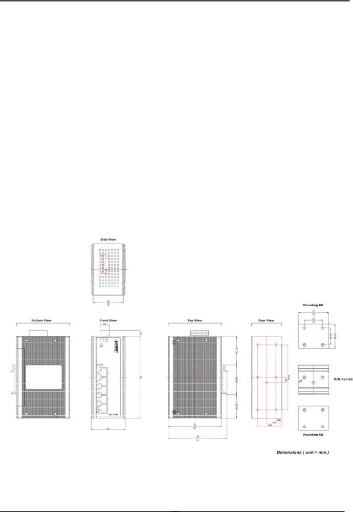
2.1.1 Physical Dimension
ISW-5xxPS series Web Smart Industrial Switch dimension (D x W x H) : 135mm x 87.8mm x 56mm
-12 -
User’s Manual
2.1.2 Front Panel
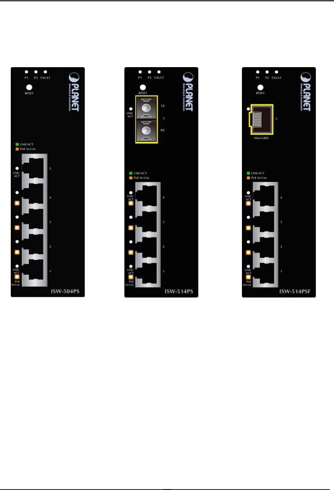
Figure 2-1 shows a front panel of Industrial PoE Switch.
Figure 2-1 ISW-504PS and ISW-514PS / ISW-514PS15 and ISW-514PF Switch front panel
■ Reset Button
At the left of front panel, the reset button is designed for reboot the Industrial PoE Switch without turn off and on the power, also can reset the Industrial PoE Switch to factory default mode.
-13 -
User’s Manual
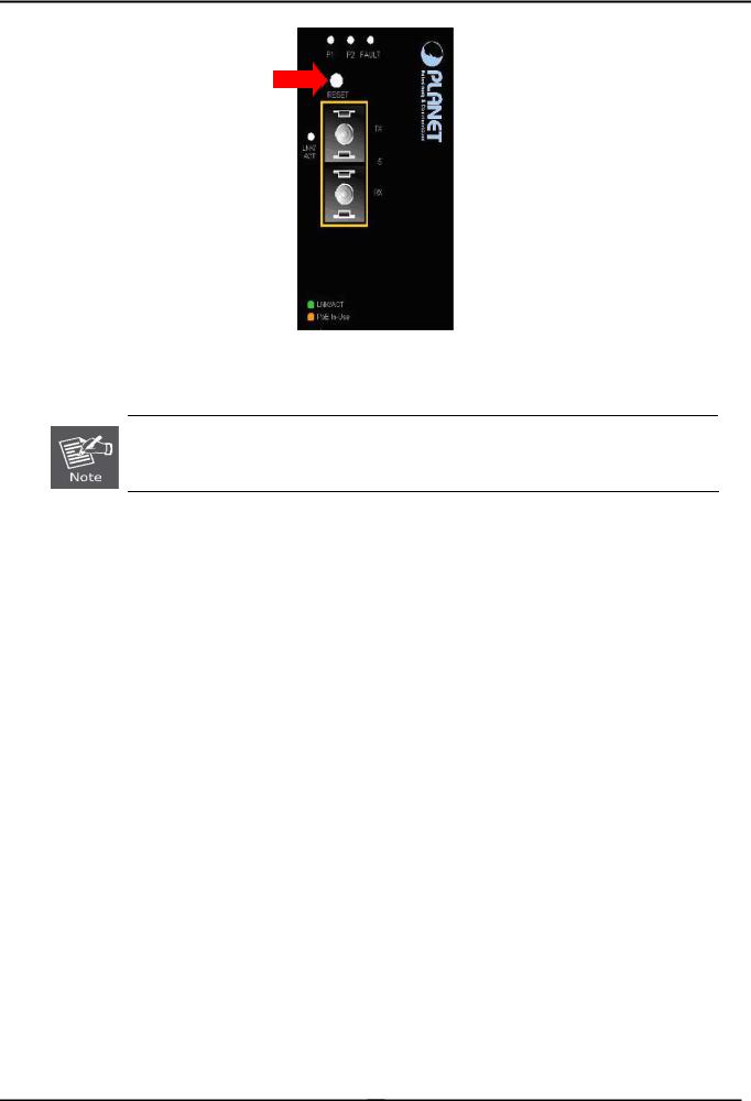
Figure 2-2 Reset button of Industrial PoE Switch
1.Press the RESET button once. The Industrial PoE Switch will reboot automatically.
2.Press the RESET button for 5 seconds. The Industrial PoE Switch will back to the factory default mode; the entire configuration will be erased.
2.1.3LED Indicators
System
|
LED |
Color |
|
Function |
|
P1 |
Green |
Indicate the power 1 has power. |
|
|
P2 |
Green |
Indicate the power 2 has power. |
|
|
|
|
|
|
|
Fault |
Green |
Indicate the either power 1 or power 2 has no power. |
|
|
|
|
|
|
Per 10/100Base-TX Port |
|
|||
|
|
|
|
|
|
LED |
Color |
|
Function |
|
|
|
Light |
Indicate the link through that port is successfully |
|
LNK / ACT |
Green |
|
established at 10 or 100Mbps. |
|
|
Indicate that the Switch is actively sending or receiving |
||
|
|
|
Blink |
|
|
|
|
data over that port. |
|
|
|
|
|
|
|
|
|
|
|
Per 100Base-FX Port |
|
|||
|
|
|
|
|
|
LED |
Color |
|
Function |
|
|
|
Light |
Indicate the link through that port is successfully established |
|
LNK/ ACT |
Green |
|
at 10 or 100Mbps. |
|
|
Indicate that the Switch is actively sending or receiving data |
||
|
|
|
Blink |
|
|
|
|
over that port. |
|
|
|
|
|
|
|
|
|
|
|
-14 -
User’s Manual
PoE Port
LED |
Color |
Function |
PoE In Use |
Orange |
Indicate the port is providing 48V DC in-line power. (1-4 ports) |
|
|
|
2.1.4 Switch Upper Panel
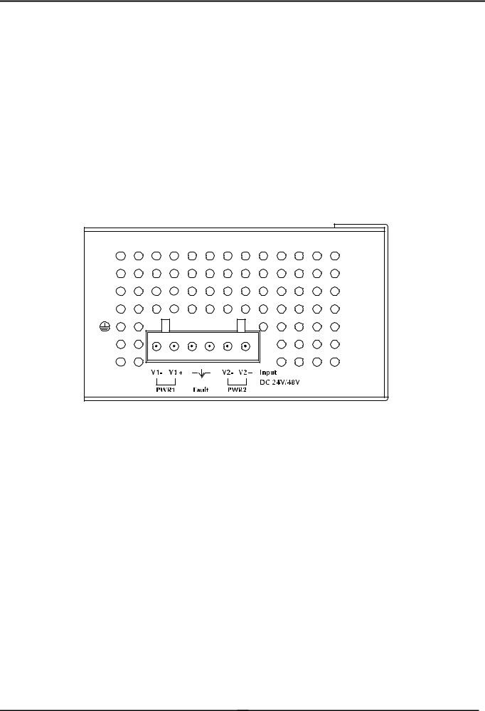
The Upper Panel of the Industrial PoE Switch indicates a DC inlet power socket and consist one terminal block connector within 6-contacts. It accepts input power from 24 or 48V DC.
Figure 2-3 Industrial PoE Switch Upper Panel
-15 -

User’s Manual
2.2 Install the switch
This section describes how to install your Managed Industrial Switch and make connections to the Managed Industrial Switch. Please read the following topics and perform the procedures in the order being presented. To install your switch on a desktop or shelf, simply complete the following steps.
In this paragraph, we will describe how to install the Industrial Switch and the installation points attended to it.
2.2.1 Installation Steps
1.Unpack the Industrial switch
2.Check if the DIN-Rail is screwed on the Industrial switch or not. If the DIN-Rail is not screwed on the Industrial switch, please refer to DIN-Rail Mounting section for DIN-Rail installation. If users want to wall mount the Industrial switch, please refer to Wall Mount Plate Mounting section for wall mount plate installation.
3.To hang the Industrial switch on the DIN-Rail track or wall.
4.Power on the Industrial switch. Please refer to the Wiring the Power Inputs section for knowing the information about how to wire the power. The power LED on the Industrial switch will light up. Please refer to the LED Indicators section for indication of LED lights.
5.Prepare the twisted-pair, straight through Category 5 cable for Ethernet connection.
6.Insert one side of RJ-45 cable (category 5) into the Industrial switch Ethernet port (RJ-45 port) and another side of RJ-45 cable (category 5) to the network device’s Ethernet port (RJ-45 port), ex: Switch PC or Server. The UTP port (RJ-45) LED on the Industrial switch will light up when the cable is connected with the network device. Please refer to the LED Indicators section for LED light indication.
Make sure that the connected network devices support MDI/MDI-X. If it does not support, use the crossover category-5 cable.
7.When all connections are set and LED lights all show in normal, the installation is complete.
2.2.2DIN-Rail Mounting
This section describes how to install the Industrial PoE Switch.
There have two methods to install the Industrial PoE Switch. DIN-Rail Mounting and Wall Mount Plate Mounting. Please read the following topics and perform the procedures in the order being presented.
-16 -

User’s Manual
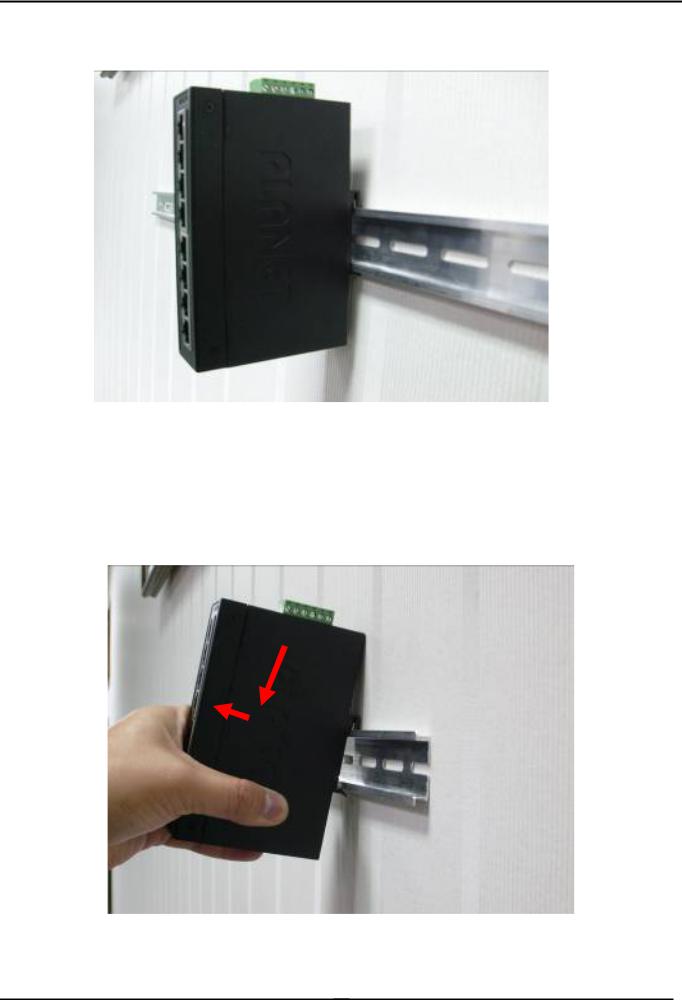
Step 1: Screw the DIN-Rail on the Industrial PoE Switch.
Step 2: Lightly press the button of DIN-Rail into the track.
-17 -
User’s Manual
Step 3: Check the DIN-Rail is tightly on the track.
Please refer to following procedures to remove the Industrial PoE Switch from the track.
Step 5: Lightly press the button of DIN-Rail for remove it from the track.
-18 -
User’s Manual
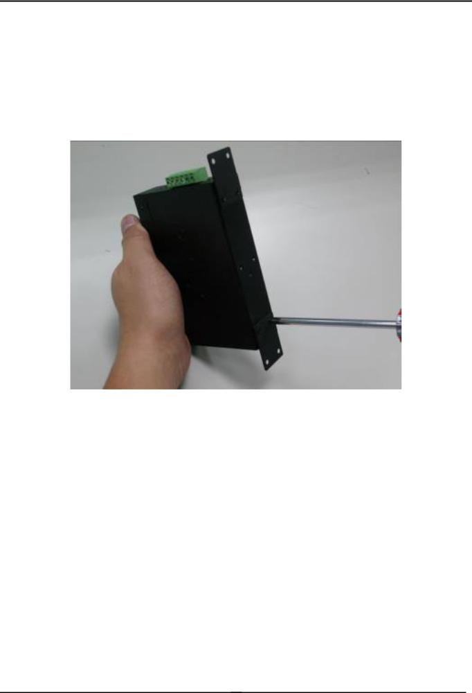
2.2.3 Wall Mount Plate Mounting
To install the Industrial PoE Switch on the wall. Please follow the instructions below.
Step 1: Remove the DIN-Rail from the Industrial PoE Switch. Use the screwdriver to loose the screws and remove the DIN-Rail.
Step 2: Place the wall mount plate on the rear panel of the Industrial PoE Switch.
Step 3: Use the screwdriver to screw the wall mount plate on the Industrial PoE Switch.
Step 4: Use the hook holes at the corners of the wall mount plate to hang the Industrial PoE Switch on the wall.
Step 5: To remove the wall mount plate, reverse steps above.
2.3 Wiring the Power Inputs
The 6-contacts terminal block connector on the top panel of Industrial PoE Switch is used for two DC redundant power inputs. Please follow the steps to insert the power wire. The PWR1 is 1(-) & 2(+) and PWR2 is 5(-) & 6(+) contact.
Remember: Tighten the wire-clamp screws for preventing the wires from loosing.
-19 -
User’s Manual
1 |
2 |
3 |
4 |
5 |
6 |
Power 1 |
|
Fault |
|
Power 2 |
|
- |
+ |
|
|
- |
+ |
Figure 2-4: 6-Contacts of Terminal Block Connector
1. The wire gauge for the terminal block should be in the range between 12 ~ 24 AWG.
Power Notice:
2. Performing any of the procedures like inserting the wires or tighten the wire-clamp screws. Ensure the power is OFF to prevent to get an electric shock.
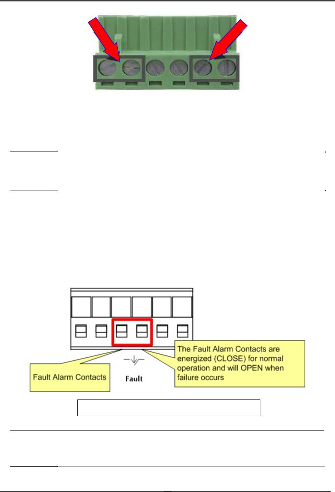
2.4 Wiring the Fault Alarm Contact
The fault alarm contacts are in the middle (3 & 4) of the terminal block connector as the picture shows below. Inserting the wires, the Industrial PoE Switch will detect the fault status of the power failure, or port link failure (available for managed model).
The following illustration shows an application example for wiring the fault alarm contacts
Insert the wires into the fault alarm contacts
1. The wire gauge for the terminal block should be in the range between 12 ~ 24 AWG.
Power Notice:
2. Performing any of the procedures like inserting the wires or tighten the wire-clamp screws. Ensure the power is OFF to prevent to get an electric shock.
-20 -
User’s Manual
2.5 Cabling
100Base-TX and 100Base-FX
The 10/100Mbps RJ-45 ports come with Auto-Negotiation capability. Users only need to plug in working network device into one of the 10/100Mbps RJ-45 ports. The ISW-504PS / ISW-514PS series will automatically run in 10Mbps or 100Mbps after the negotiation with the connected device. The ISW-514PS has one 100Base-FX SC Interface (Multi-mode, 50/125μm or 62.5/125μm fiber cable and the available distance is 2km). The ISW-514PS15 has one 100Base-FX SC Interface (Single-mode, 9 / 125μm fiber cable and the available distance is 15km). The ISW-514PSF has one 100Base-FX SFP interface (Optional Multi-mode / Single-mode 100Base-FX SFP module)
Cabling
Each 10/100Base-TX ports use RJ-45 sockets -- for connection of unshielded twisted-pair cable (UTP).
The 100Base-FX port is uses as SC / LC connector. Please see table below and know more about the cable’s specification.
Port Type |
Cable Type |
Connector |
||
|
|
|
|
|
10Base-T |
Cat 3, 4, 5, 2-pair |
RJ-45 |
||
|
|
|
||
100Base-TX |
Cat.5, 5e, 6 UTP, 2-pair |
RJ-45 |
||
|
|
|
|
|
100Base-FX |
50 |
/ 125μm or 62.5/125μm |
SC (Multi-mode) |
|
|
|
|
||
100Base-FX |
9 / 125μm |
SC (Single-mode) |
||
|
|
|
|
|
100Base-FX |
50 |
/ 125µm or 62.5 / 125µm multi-mode |
LC (Multi / Single mode) |
|
9 / 125µm single-mode |
||||
|
|
|||
|
|
|
|
|
Any Ethernet devices like Hubs / PCs can connect to the Industrial PoE Switch by using straight-through wires. The 10/100Mbps RJ-45 ports are auto-MDI / MDI-X can be used on straight-through or crossover cable.
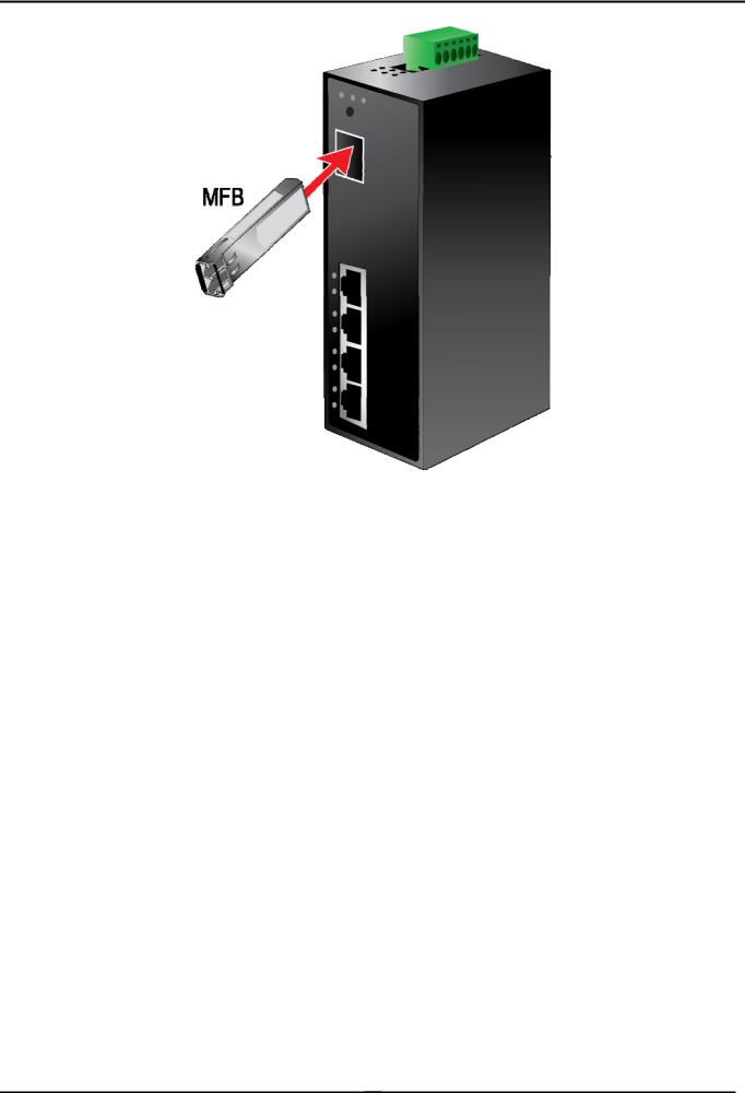
2.5.1 Installing the SFP transceiver (ISW-514PSF Only)
The sections describe how to insert an SFP transceiver into an SFP slot.
The SFP transceivers are hot-pluggable and hot-swappable. You can plug-in and out the transceiver to/from any SFP port without having to power down the Switch/Media Converter. As the Figure 2-6 appears.
-21 -
User’s Manual
Figure 2-6 Plug-in the SFP transceiver
Before connect the other switches, workstation or Media Converter.
1.Make sure both side of the SFP transceiver are with the same media type or WDM pair, for example: 100Base-FX to 100Base-FX, 100Base-BX20-U to 100Base-BX20-D.
2.Check the fiber-optic cable type match the SFP transceiver model.
¾To connect to MFB-FX SFP transceiver, use the multi-mode fiber cablewith one side must be male duplex LC connector type.
¾To connect to MFB-F20/F40/F60/FA20/FB20 SFP transceiver, use the single-mode fiber cable-with one side must be male duplex LC connector type.
Connect the fiber cable
1.Attach the duplex LC connector on the network cable into the SFP transceiver.
2.Connect the other end of the cable to a device – switches with SFP installed, fiber NIC on a workstation or a Media Converter.
3.Check the LNK/ACT LED of the SFP slot of the switch / converter. Ensure that the SFP transceiver is operating correctly.
4.Check the Link mode of the SFP port if the link failed. Co works with some fiber-NICs or Media Converters, set the Link mode to “100 Force” is needed.
-22 -
User’s Manual
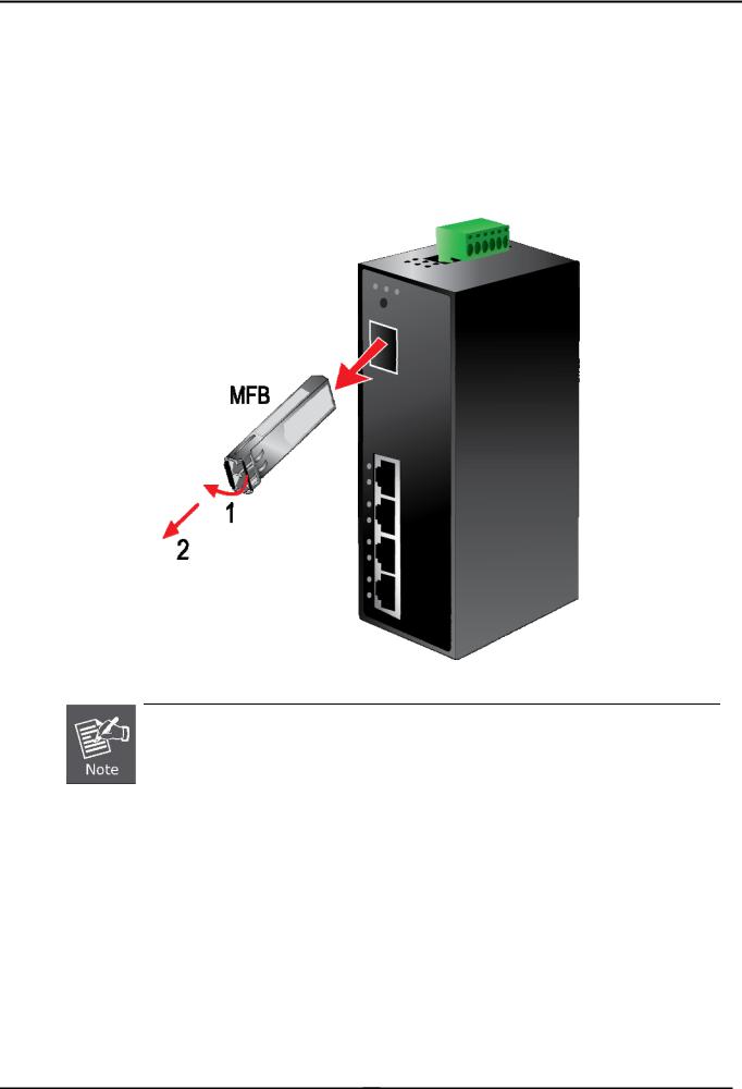
2.5.2 Remove the module
1.Make sure there is no network activity by consult or check with the network administrator. Or through the management interface of the switch/converter (if available) to disable the port in advance.
2.Remove the Fiber Optic Cable gently.
3.Turn the handle of the MFB module to horizontal.
4.Pull out the module gently through the handle.
Figure 2-7 Pull Out the SFP transceiver
Never pull out the module without pull the handle or the push bolts on the module. Direct pull out the module with violent could damage the module and SFP module slot of the device.
-23 -

User’s Manual
3 MANAGEMENT
This chapter describes how to manage the Industrial PoE Switch Topics include:
-Overview
-Management method
-Logging on to the Industrial PoE Switch
3.1 Overview
The Industrial PoE Switch provides a user-friendly, Web interface. Using this interface, you can perform various device configuration and management activities, including:
System
Power over Ethernet
Tools
3.2Requirements
Network cables. Use standard network (UTP) cables with RJ-45 connectors.
Subscriber PC installed with Ethernet NIC (Network Card)
The operate system of subscriber PC that running Windows XP/2003, Vista, Windows 7, MAC OS X , Linux, Fedora, Ubuntu or other platform compatible with TCP/IP protocols.
It is recommended to use Internet Explore 7.0 or above to access Industrial PoE Switch.
3.3 Management Method
User can manage the Industrial PoE Switch by Web Management via a network connection.
3.3.1 Web Management
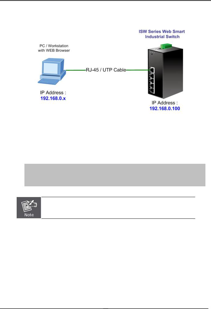
The Industrial PoE Switch can be configured through an Ethernet connection, make sure the manager PC must be set on same the IP subnet address with the Industrial PoE Switch.
For example, if you have changed the default IP address of the Device to 192.168.99.123 with subnet mask 255.255.255.0 via console, then the manager PC should be set at 192.168.99.x (where x is a number between 2 and 254) with subnet mask 255.255.255.0. Or you can use the factory default IP address 192.168.0.100 to do the relative configuration on manager PC.
-24 -
User’s Manual
1.Use Internet Explorer 7.0 or above Web browser. Enter IP address http://192.168.0.100 (the factory-default IP address) to access the Web interface.
Figure 3-1 Web Management over Ethernet
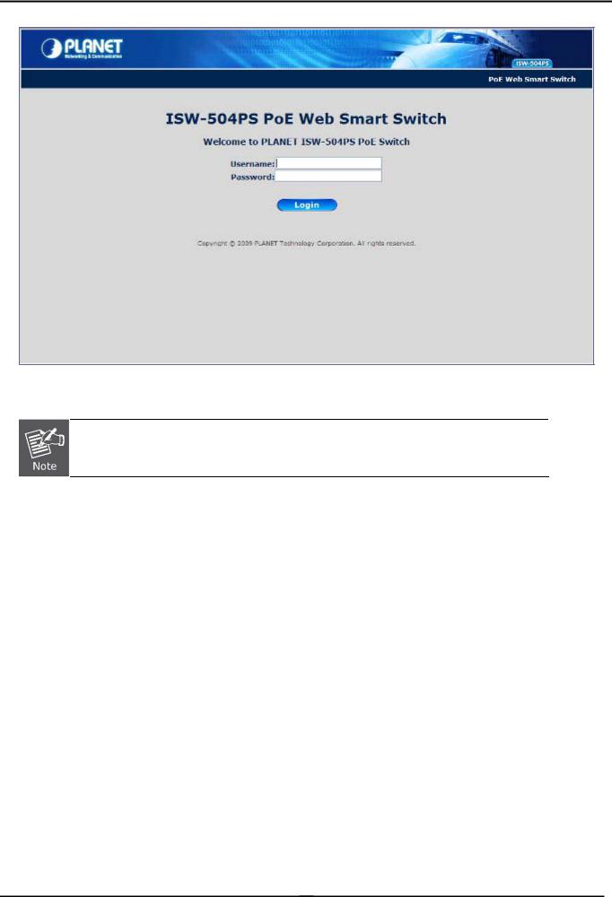
2.When the following login screen appears, please enter Planet’s default Username "admin" and Password “admin” to login the main screen of Industrial PoE Switch. The login screen in Figure 3-2 appears.
3.
Default IP Address: 192.168.0.100
Default Account: admin
Default Password: admin
The following screen based on ISW-504PS, for ISW-514PS / ISW-514PS15 / ISW-514PSF.
-25 -
User’s Manual
Figure 3-2 Web Login screen
1.For security reason, please changes and remembers the new password after this first setup.
2.Only accept command in lowercase letter under WEB interface.
-26 -
User’s Manual
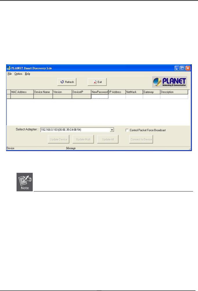
3.3.2 PLANET Smart Discovery Utility
For easily list the Industrial PoE Switch in your Ethernet environment, the Planet Smart Discovery Utility from user’s manual CD-ROM is an ideal solution.
The following install instructions guiding you for run the Planet Smart Discovery Utility.
1.Deposit the Planet Smart Discovery Utility in administrator PC.
2.Run this utility and the following screen appears.
Figure 3-3 PLANET Smart Discovery Utility Screen
If there are two LAN cards or above in the same administrator PC, choose different LAN card by use the
“Select Adapter” tool.
3.Press “Refresh” button for list current connected devices in the discovery list, the screen is shown as follow.
-27 -
Loading...