


 Loading...
User’s Manual
ISW-1022M
ISW-1022MT
8-Port 10/100Mbps + 2 Gigabit TP/SFP Managed Industrial Switch
ISW-1022MPT
8-Port 10/100Mbps + 2 Gigabit TP/SFP PoE Managed Industrial Switch
ISW-1033MT
7-Port 10/100Mbps + 3 Gigabit TP/SFP Managed Industrial Switch

User’s Manual of ISW-1022M Series and ISW-1033MT
Trademarks
Copyright © PLANET Technology Corp. 2009. Contents subject to which revision without prior notice.
PLANET is a registered trademark of PLANET Technology Corp. All other trademarks belong to their respective owners.
Disclaimer
PLANET Technology does not warrant that the hardware will work properly in all environments and applications, and makes no warranty and representation, either implied or expressed, with respect to the quality, performance, merchantability, or fitness for a particular purpose.
PLANET has made every effort to ensure that this User's Manual is accurate; PLANET disclaims liability for any inaccuracies or omissions that may have occurred.
Information in this User's Manual is subject to change without notice and does not represent a commitment on the part of PLANET. PLANET assumes no responsibility for any inaccuracies that may be contained in this User's Manual. PLANET makes no commitment to update or keep current the information in this User's Manual, and reserves the right to make improvements to this User's Manual and/or to the products described in this User's Manual, at any time without notice.
If you find information in this manual that is incorrect, misleading, or incomplete, we would appreciate your comments and suggestions.
FCC Warning
This equipment has been tested and found to comply with the limits for a Class A digital device, pursuant to Part 15 of the FCC Rules. These limits are designed to provide reasonable protection against harmful interference when the equipment is operated in a commercial environment. This equipment generates, uses, and can radiate radio frequency energy and, if not installed and used in accordance with the Instruction manual, may cause harmful interference to radio communications. Operation of this equipment in a residential area is likely to cause harmful interference in which case the user will be required to correct the interference at whose own expense.
CE Mark Warning
This is a Class A product. In a domestic environment, this product may cause radio interference, in which case the user may be required to take adequate measures.
WEEE Warning
To avoid the potential effects on the environment and human health as a result of the presence of hazardous substances in electrical and electronic equipment, end users of electrical and electronic equipment should understand the meaning of the crossed-out wheeled bin symbol. Do not dispose of WEEE as unsorted municipal waste and have to collect such WEEE separately.
Revision
8-Port 10/100Mbps + 2 Gigabit TP/SFP Managed Industrial Switch User’s Manual FOR MODELS: ISW-1022M / ISW-1022MT / ISW-1022MPT / ISW-1033MT REVISION: 1.2 (NOVEMBER.2009)
Part No.: EM-ISW1022M_v1.2 (2081-AH0010-002)
2
User’s Manual of ISW-1022M Series and ISW-1033MT |
|
TABLE OF CONTENTS |
|
1. INTRODUCTION ............................................................................. |
6 |
1.1 PACKAGE CONTENTS .............................................................................................................................. |
6 |
1.2 PRODUCT DESCRIPTION........................................................................................................................... |
6 |
1.3 PRODUCT FEATURES ............................................................................................................................... |
7 |
1.4 PRODUCT SPECIFICATION ...................................................................................................................... |
10 |
1.4.1 ISW-1022M / ISW-1022MT Product Specification .................................................................... |
10 |
1.4.2 ISW-1022MPT Product Specification ........................................................................................ |
12 |
1.4.3 ISW-1033MT Product Specification .......................................................................................... |
15 |
2. INSTALLATION............................................................................. |
18 |
2.1 HARDWARE DESCRIPTION...................................................................................................................... |
18 |
2.1.1 Physical Dimension ................................................................................................................... |
18 |
2.1.2 Front / Rear Panel ..................................................................................................................... |
21 |
2.1.3 Top View.................................................................................................................................... |
24 |
2.1.4 LED Indicators ........................................................................................................................... |
25 |
2.2 INSTALL THE SWITCH ............................................................................................................................. |
30 |
2.2.1 Installation Steps ....................................................................................................................... |
30 |
2.2.2 DIN-Rail Mounting ..................................................................................................................... |
31 |
2.2.3 Wall Mount Plate Mounting........................................................................................................ |
32 |
2.2.4 Wiring the Power Inputs ............................................................................................................ |
33 |
2.2.5 Wiring the Fault Alarm Contact.................................................................................................. |
34 |
2.2.6 Wiring the Digital Inputs / Outputs (ISW-1033MT) .................................................................... |
35 |
2.2.7 Installing the SFP transceiver.................................................................................................... |
36 |
3. NETWORK APPLICATION.............................................................. |
39 |
3.1 RAPID RING APPLICATION...................................................................................................................... |
40 |
3.2 COUPLING RING APPLICATION ............................................................................................................... |
40 |
3.3 DUAL HOMING APPLICATION.................................................................................................................. |
41 |
4. CONSOLE MANAGEMENT .............................................................. |
42 |
4.1 CONNECTING TO THE CONSOLE PORT .................................................................................................... |
42 |
4.2 PIN ASSIGNMENT................................................................................................................................... |
42 |
4.3 LOGIN IN THE CONSOLE INTERFACE ....................................................................................................... |
43 |
4.4 CLI MANAGEMENT ................................................................................................................................ |
45 |
4.5 COMMANDS LEVEL ................................................................................................................................ |
46 |
5. WEB-BASED MANAGEMENT .......................................................... |
47 |
5.1 ABOUT WEB-BASED MANAGEMENT........................................................................................................ |
47 |
5.2 REQUIREMENTS..................................................................................................................................... |
48 |
5.3 LOGGING ON THE SWITCH ...................................................................................................................... |
48 |
5.4 SYSTEM ................................................................................................................................................ |
50 |
3
User’s Manual of ISW-1022M Series and ISW-1033MT |
|
5.4.1 System Information.................................................................................................................... |
51 |
5.4.2 IP Configuration......................................................................................................................... |
52 |
5.4.3 DHCP Server............................................................................................................................. |
53 |
5.4.4 TFTP.......................................................................................................................................... |
56 |
5.4.5 System Event Log ..................................................................................................................... |
58 |
5.4.6 Fault Relay Alarm ...................................................................................................................... |
62 |
5.4.7 SNTP Configuration................................................................................................................... |
63 |
5.4.8 IP Security ................................................................................................................................. |
66 |
5.4.9 User Authentication ................................................................................................................... |
67 |
5.5 PORT MANAGEMENT.............................................................................................................................. |
68 |
5.5.1 Port Statistics............................................................................................................................. |
68 |
5.5.2 Port Control................................................................................................................................ |
69 |
5.5.3 Port Trunk.................................................................................................................................. |
70 |
5.5.4 Port Mirroring............................................................................................................................. |
77 |
5.5.5 Rate Limiting.............................................................................................................................. |
78 |
5.6 PROTOCOL............................................................................................................................................ |
79 |
5.6.1 VLAN configuration.................................................................................................................... |
79 |
5.6.2 Rapid Spanning Tree................................................................................................................. |
90 |
5.6.3 SNMP Configuration................................................................................................................ |
100 |
5.6.4 QoS Configuration ................................................................................................................... |
105 |
5.6.5 IGMP Snooping ....................................................................................................................... |
110 |
5.6.6 X-Ring...................................................................................................................................... |
115 |
5.7 SECURITY ........................................................................................................................................... |
119 |
5.7.1 Security—802.1X/Radius Configuration.................................................................................. |
119 |
5.7.2 MAC Address Table ................................................................................................................ |
125 |
5.8 DIGITAL INPUT/OUTPUT (ISW-1033MT)............................................................................................... |
129 |
5.8.1 Digital Input.............................................................................................................................. |
129 |
5.8.2 Digital Output........................................................................................................................... |
130 |
5.9 POWER OVER ETHERNET ..................................................................................................................... |
131 |
5.9.1 Power over Ethernet Powered Device .................................................................................... |
131 |
5.9.2 Power Management: ............................................................................................................... |
131 |
5.10 FACTORY DEFAULT ........................................................................................................................... |
135 |
5.11 SAVE CONFIGURATION ...................................................................................................................... |
135 |
5.12 SYSTEM REBOOT .............................................................................................................................. |
136 |
6. COMMAND SETS ......................................................................... |
137 |
6.1 SYSTEM COMMANDS SET..................................................................................................................... |
137 |
6.2 PORT COMMANDS SET ........................................................................................................................ |
139 |
6.3 TRUNK COMMANDS SET ...................................................................................................................... |
141 |
6.4 VLAN COMMANDS SET ....................................................................................................................... |
142 |
6.5 SPANNING TREE COMMANDS SET ........................................................................................................ |
143 |
6.6 QOS COMMANDS SET ......................................................................................................................... |
145 |
4
User’s Manual of ISW-1022M Series and ISW-1033MT |
|
6.7 IGMP COMMANDS SET........................................................................................................................ |
145 |
6.8 MAC / FILTER TABLE COMMANDS SET................................................................................................. |
146 |
6.9 SNMP COMMANDS SET....................................................................................................................... |
146 |
6.10 PORT MIRRORING COMMANDS SET .................................................................................................... |
148 |
6.11 802.1X COMMANDS SET .................................................................................................................... |
149 |
6.12 TFTP COMMANDS SET ...................................................................................................................... |
150 |
6.13 SYSTEMLOG, SMTP AND EVENT COMMANDS SET .............................................................................. |
151 |
6.14 SNTP COMMANDS SET ..................................................................................................................... |
152 |
6.15 X-RING COMMANDS SET .................................................................................................................... |
153 |
6.16 POE COMMAND SET.......................................................................................................................... |
153 |
7. SWITCH OPERATION.................................................................. |
155 |
7.1 ADDRESS TABLE ................................................................................................................................. |
155 |
7.2 LEARNING ........................................................................................................................................... |
155 |
7.3 FORWARDING & FILTERING .................................................................................................................. |
155 |
7.4 STORE-AND-FORWARD ........................................................................................................................ |
155 |
7.5 AUTO-NEGOTIATION ............................................................................................................................ |
156 |
8. POWER OVER ETHERNET OVERVIEW.......................................... |
157 |
WHAT IS POE? ......................................................................................................................................... |
157 |
THE POE PROVISION PROCESS ................................................................................................................. |
159 |
Stages of powering up a PoE link..................................................................................................... |
159 |
Line Detection................................................................................................................................... |
159 |
Classification..................................................................................................................................... |
159 |
Start-up ............................................................................................................................................. |
160 |
Operation .......................................................................................................................................... |
160 |
Power Disconnection Scenarios....................................................................................................... |
160 |
APPENDIX A—RJ-45 PIN ASSIGNMENT .......................................... |
161 |
A.1 SWITCH'S RJ-45 PIN ASSIGNMENTS .................................................................................................... |
161 |
A.2 10/100MBPS, 10/100BASE-TX........................................................................................................... |
161 |
APPENDIX B TROUBLES SHOOTING ............................................... |
163 |
5

User’s Manual of ISW-1022M Series and ISW-1033MT
1. Introduction
The PLANET Layer 2 Managed Industrial Switch series - ISW-1022M series and ISW-1033MT are multiple 10/100Mbps ports Ethernet Switched with Gigabit TP/SFP fiber optical combo connective ability and robust layer 2 features; the description of these models as below:
ISW-1022M :
ISW-1022MT :
ISW-1022MPT :
ISW-1033MT :
8-Port 10/100Base-TX + 2-Port Gigabit TP/SFP Combo Managed Industrial Ethernet Switch (-10 ~ 60 Degree C)
8-Port 10/100Base-TX + 2-Port Gigabit TP/SFP Combo Managed Industrial Ethernet Switch (-40 ~ 75 Degree C)
8-Port 10/100Base-TX + 2-Port Gigabit TP/SFP Combo Managed Industrial PoE Switch (-40 ~ 75 Degree C)
7-Port 10/100Base-TX + 3-Port Gigabit TP/SFP Combo Managed Industrial Ethernet Switch (-40 ~ 75 Degree C)
Terms of “Managed Industrial Switch” means the Switches mentioned titled in the cover page of this User’s manual, i.e.ISW-1022M, ISW-1022MT, ISW-1022MPT, and ISW-1033MT.
1.1 Package Contents
Please refer to the package content list below to verify them against the checklist.
The Managed Industrial Switch x 1
User Manual x 1
Pluggable Terminal Block x 1
Mounting Plate x 2
RJ-45 to DB9-Female Cable x 1
If any of these are missing or damaged, please contact your dealer immediately, if possible, retain the carton including the original packing material, and use them against to repack the product in case there is a need to return it to us for repair.
1.2 Product Description
Increases Reliability in Industrial Networks
The PLANET ISW-1022M series and ISW-1033MT Managed Industrial Ethernet Switches is industrially hardened. Ethernet switch specifically designed to operate reliably in electrically harsh and climatically demanding environments. It incorporates Redundant Data Ring technology and redundant power supply system into customers’ industrial automation network to enhance system reliability and uptime in the factory harsh environments. It protects customer’s industrial network connectivity with switching recovery capability. The ISW-1022M series and ISW-1033MT provides IP-30 aluminum case and 8 10/100Mbps Fast Ethernet ports and 2 Gigabit TP/SFP combo interfaces. The Gigabit fiber optical
6

User’s Manual of ISW-1022M Series and ISW-1033MT
uplink capability can guarantee the throughput to all nodes hooked into the network and distance can be extended up to above 120 kilometers with SFP module.
Its advanced features, such as IGMP snooping, broadcast storm control, MAC address filtering, Virtual LAN, enhanced security and bandwidth utilization fit a variety of applications. Additionally, its standard-compliant implementation ensures interoperability with equipment from other vendors.
With ISW-1022M series and ISW-1033MT built in Simple Network Management Protocol (SNMP) and Web-based management, the ISW-1022M series and ISW-1033MT offers an easy-to-use, platform-independent management and configuration facility. For text-based management, the ISW-1022M series and ISW-1033MT can also be accessed via Telnet and the console port.
1.3 Product Features
Physical Port ISW-1022M / ISW-1022MT
8-Port 10/100Base-TX RJ-45 copper interface
2-Port gigabit TP/SFP combo interface, SFP(Mini-GBIC) supports 100/1000 Dual Mode
1 RJ-45 Console interface for Switch basic management and setup
ISW-1022MPT
8-Port 10/100Base-TX RJ-45 copper with 8 IEEE 802.3af PoE injector
2-Port gigabit TP/SFP combo interface, SFP(Mini-GBIC) supports 100/1000 Dual Mode
1 RJ-45 Console interface for Switch basic management and setup
ISW-1033MT
7-Port 10/100Base-TX RJ-45 copper interface
3-Port gigabit TP/SFP combo interface, SFP(Mini-GBIC) supports 100/1000 Dual Mode
1 RJ-45 Console interface for Switch basic management and setup
Layer 2 Features
Complies with the IEEE 802.3, IEEE 802.3u, IEEE 802.3ab, IEEE 802.3z Gigabit Ethernet standard
High performance Store and Forward architecture, broadcast storm control, runt/CRC filtering eliminates erroneous packets to optimize the network bandwidth
Support VLANs:
•IEEE 802.1Q Tag-Based VLAN
•Up to 256 VLANs groups, out of 4096 VLAN IDs
•Port-Based VLAN
•GVRP (GARP VLAN Registration Protocol), up to 256 groups
Support up to 4 Trunk groups, each trunk for up to maximum 4 port with 800Mbps bandwidth(Duplex Mode)
Support Spanning Tree Protocol:
7

User’s Manual of ISW-1022M Series and ISW-1033MT
•IEEE 802.1d classic Spanning Tree Algorithm
•IEEE 802.1w Rapid Spanning Tree Protocol
Rapid Data Redundant Ring
Support Rapid Ring topology mode:
•Dual Homing Ring
•Couple Ring
Provide redundant backup feature and the recovery time below 20ms
Quality of Service
Support IEEE 802.1p Class of Service
4 priority queues on all switch ports
QoS Mode: Port Base, Tag Base and Type of Service Priority
Support for strict priority and weighted round robin (WRR) CoS policies
Ingress/Egress Bandwidth control on each port
Multicast
IGMP Snooping v1 and v2
IGMP Query mode for Multicast Media application
256 multicast groups
Security
IEEE 802.1x Port-Based Authentication
MAC address Filtering and MAC address Binding
IP address security management to prevent unauthorized intruder
Port Mirroring to monitor the incoming or outgoing traffic on a particular port
Power over Ethernet (ISW-1022MPT)
Complies with IEEE 802.3af Power over Ether Internet End-Span PSE
Provides 8 IEEE 802.3af devices powered
Support PoE power up to 15.4 watts for each PoE ports
Auto detected powered device (PD)
Circuit protection prevent power interference between ports
Remote power feeding uo to 100m
PoE management
zTotal power budget control
zPer port PoE function enable.disable
zPoE port power feeding priority
zPer PoE port power limit
zPD classification detection
8

User’s Manual of ISW-1022M Series and ISW-1033MT
Management
WEB-based, Telnet, Console Command Line management
Access through SNMP v1, v2c and v3 set and get requests
SNMP Trap / SMTP email for alarm notification of events
System Log Server/Client
Industrial Case / Installation
IP-30 Aluminum case protection
DIN Rail and Wall Mount Design
Redundant Power Design
9

User’s Manual of ISW-1022M Series and ISW-1033MT
1.4 Product Specification
1.4.1 ISW-1022M / ISW-1022MT Product Specification
Product |
ISW-1022M |
ISW-1022MT |
|
|
|
|
|
Hardware Specification |
|
|
|
|
|
|
|
Copper Ports |
8 10/ 100Base-TX RJ-45 Auto-MDI/MDI-X ports |
||
2 10/100/1000Base-T RJ-45 port |
|
||
|
|
||
|
|
||
SFP/mini-GBIC Slots |
2 SFP interfaces, shared with Port-9 and Port-10 |
||
|
|
|
|
Switch Architecture |
Store-and-Forward |
|
|
|
|
|
|
Switch Fabric |
5.6Gbps / non-blocking |
|
|
|
|
|
|
Switch Throughput |
8.3Mpps@64Bytes |
|
|
|
|
|
|
Address Table |
8K entries |
|
|
|
|
|
|
Share Data Buffer |
1Mbit |
|
|
|
|
|
|
Flash |
4Mbytess |
|
|
|
|
|
|
DRAM |
32Mbytes |
|
|
|
|
|
|
Maximum Frame Size |
1522 Bytes packet |
|
|
|
|
|
|
Flow Control |
Back pressure for half duplex, IEEE 802.3x Pause Frame for full duplex |
||
|
|
|
|
|
System: |
|
|
|
Power (Green) |
|
|
|
Power 1 (Green) |
|
|
|
Power 2 (Green) |
|
|
|
Fault (Red) |
|
|
LED |
8 port 10/100: |
|
|
|
Link/Activity (Green) |
|
|
|
Full duplex/Collision (Yellow) |
|
|
|
SFP port: |
|
|
|
LNK/ACT(Green) |
|
|
|
1000T: LNK/ACT(Green), 1000M(Green) |
||
|
|
||
Console Interface |
One RJ-45-to –RS-232 male connector for switch management |
||
|
|
|
|
Power Supply |
External Power Supply: DC 12~48V, Redundant power DC 12~48V and |
||
connective removable terminal block for master and slave power |
|||
|
|||
|
|
|
|
Power Consumption |
8.16 Watts (Full load) |
|
|
|
|
|
|
Operating Temperature |
-10 Degree C~60 Degree C |
-40 Degree C~75 Degree C |
|
|
|
|
|
Operating Humidity |
5% to 95% (Non-condensing) |
|
|
|
|
|
|
Storage Temperature |
-40 Degree C ~ 85 Degree C |
|
|
|
|
|
|
Case Dimension |
IP-30, 2.83” x 4.13” x 5.98” / 72mm x 105mm x 152mm |
||
|
|
|
|
10
|
User’s Manual of ISW-1022M Series and ISW-1033MT |
|
|
|
|
Management Functions |
|
|
|
|
|
Management Interface |
Console, Telnet, Web Browser, SNMP v1, v2c and v3 |
|
|
|
|
|
Port disable/enable. |
|
Port Configuration |
Auto-negotiation 10/100Mbps full and half duplex mode selection. |
|
|
Flow Control disable / enable. Bandwidth control on each port. |
|
|
|
|
Port Status |
Display each port’s speed duplex mode, link status, Flow control status. Auto |
|
negotiation status |
|
|
|
|
|
|
|
|
VLAN |
Port-Based VLAN, up to 9 VLAN groups |
|
IEEE 802.1q Tagged Based VLAN , 4K VLAN ID, up to 256 VLAN groups |
|
|
|
|
|
|
|
|
Spanning Tree |
IEEE 802.1d Spanning Tree |
|
IEEE 802.1w Rapid Spanning Tree |
|
|
|
|
|
|
|
|
Link Aggregation |
Supports 4 groups of 4-Port trunk support |
|
|
|
|
|
Traffic classification based on : |
|
QoS |
Port Number, |
|
802.1Q Tag, |
|
|
|
802.1p priority, |
|
|
IP DSCP/TOS field in IP Packet |
|
IGMP Snooping |
v1 and v2 |
|
256 multicast groups and IGMP query |
|
|
|
|
|
|
|
|
|
Per port bandwidth control |
|
Bandwidth Control |
Ingress: 500Kb~80Mbps |
|
|
Egress: 64Kb~80Mbps |
|
|
|
|
Port Mirror |
RX/TX/Both |
|
|
|
|
|
Support 100 entries of MAC address for static MAC and another 100 for MAC filter |
|
Security |
Support 10 IP addresses that have permission to access the switch management |
|
|
and to prevent unauthorized intruder |
|
|
|
|
Relay Alarm |
Provides one relay output for port breakdown, power fail |
|
Alarm Relay current carry ability: 1A @ DC24V |
|
|
|
|
|
|
|
|
DHCP Protocol |
Provides DHCP Client/ DHCP Server/ Port and IP Binding |
|
|
|
|
|
RFC-1157 SNMP MIB |
|
|
RFC-1213 MIB-II |
|
|
RFC-1215 Trap |
|
SNMP MIBs |
RFC-2863 Interface MIB |
|
RFC-1493 Bridge MIB |
|
|
|
|
|
|
RFC-2674 Extended Bridge MIB (Q-Bridge) |
|
|
RFC-1643, RFC-1157 RSTP MIB |
|
|
Private MIB |
|
Standards Conformance |
|
|
|
|
|
Regulation Compliance |
FCC Class A, |
|
CE EN61000-4-2, |
|
|
|
|
|
11

User’s Manual of ISW-1022M Series and ISW-1033MT
|
CE EN61000-4-3, |
|
|
||
|
CE EN-61000-4-4, |
|
|
CE EN61000-4-5, |
|
|
CE EN61000-4-6, |
|
|
CE EN61000-4-8, |
|
|
CE EN61000-4-11, |
|
|
CE EN61000-4-12, |
|
|
CE EN61000-6-2, |
|
|
CE EN61000-6-4 |
|
|
IEEE 802.3 10Base-T |
|
|
IEEE 802.3u 100Base-TX/100Base-FX |
|
|
IEEE 802.3z Gigabit SX/LX |
|
|
IEEE 802.3ab Gigabit 1000T |
|
Standards Compliance |
IEEE 802.3x Flow Control and Back pressure |
|
IEEE 802.1d Spanning tree protocol |
||
|
||
|
IEEE 802.1w Rapid spanning tree protocol |
|
|
IEEE 802.1p Class of service |
|
|
IEEE 802.1Q VLAN Tagging |
|
|
IEEE 802.1x Port Authentication Network Control |
|
|
• 50 / 125µm or 62.5 / 125µm multi-mode fiber cable, up to 220 / 550m |
|
Cable-Fiber-optic cable |
• 9 / 125µm single-mode cable, provides long distance for 10 / 15 / 20 / 30 / 40 / 50 |
|
|
/ 60 / 70 / 120km (very on fiber transceiver or SFP module) |
|
|
|
|
|
IEC60068-2-32 (Free fall) |
|
Stability Testing |
IEC60068-2-27 (Shock) |
|
|
IEC60068-2-6 (Vibration) |
|
|
|
1.4.2 ISW-1022MPT Product Specification
Product |
ISW-1022MPT |
||
|
|
|
|
Hardware Specification |
|
|
|
|
|
|
|
Copper Ports |
8 |
10/ 100Base-TX RJ-45 Auto-MDI/MDI-X ports |
|
2 |
10/100/1000Base-T RJ-45 port |
||
|
|||
|
|
|
|
SFP/mini-GBIC Slots |
2 |
SFP interfaces, shared with Port-9 and Port-10 |
|
|
|
|
|
Switch Architecture |
Store-and-Forward |
||
|
|
|
|
Switch Fabric |
5.6Gbps / non-blocking |
||
|
|
|
|
Switch Throughput |
8.3Mpps@64Bytes |
||
|
|
|
|
Address Table |
8K entries |
||
|
|
|
|
Share Data Buffer |
1Mbit |
||
|
|
|
|
Flash |
4Mbytess |
||
|
|
|
|
DRAM |
32Mbytes |
||
|
|
|
|
Maximum Frame Size |
1522 Bytes packet |
||
|
|
|
|
12

|
User’s Manual of ISW-1022M Series and ISW-1033MT |
|
|
|
|
Flow Control |
Back pressure for half duplex, IEEE 802.3x Pause Frame for full duplex |
|
|
|
|
|
System: |
|
|
Power (Green) |
|
|
Power 1 (Green) |
|
|
Power 2 (Green) |
|
|
Fault (Red) |
|
|
8 port 10/100: |
|
LED |
Link/Activity (Green) |
|
|
Full duplex/Collision (Yellow) |
|
|
SFP port: |
|
|
LNK/ACT(Green) |
|
|
1000T: LNK/ACT(Green), 1000M(Green) |
|
|
8 PoE power output: |
|
|
PoE In-Use (Green) |
|
|
|
|
Console Interface |
One RJ-45-to –RS-232 male connector for switch management |
|
|
|
|
|
External Power Supply: DC 48V |
|
Power Supply |
Redundant power DC 48V |
|
|
Removable terminal block for master and slave power |
|
Power Consumption |
128 Watts (Full load) |
|
|
|
|
Operating Temperature |
-40 Degree C~75 Degree C |
|
|
|
|
Operating Humidity |
5% to 95% (Non-condensing) |
|
|
|
|
Storage Temperature |
-40 Degree C ~ 85 Degree C |
|
|
|
|
Case Dimension |
IP-30, 2.83” x 4.13” x 5.98” / 72mm x 105mm x 152mm |
|
|
|
|
Power over Ethernet |
|
|
|
|
|
PoE Standard |
IEEE 802.3af PSE (Power Sourcing Equipment) |
|
|
|
|
Units can be Powered |
8 |
|
|
|
|
PoE Power Output |
48V DC, Max. 15.4 watts, 350mA |
|
|
|
|
Power Pin Assignment |
1/2(+), 3/6(-) |
|
|
|
|
Management Functions |
|
|
|
|
|
Management Interface |
Console, Telnet, Web Browser, SNMP v1, v2c and v3 |
|
|
|
|
|
Port disable/enable. |
|
Port Configuration |
Auto-negotiation 10/100Mbps full and half duplex mode selection. |
|
|
Flow Control disable / enable. Bandwidth control on each port. |
|
|
|
|
Port Status |
Display each port’s speed duplex mode, link status, Flow control status. Auto |
|
negotiation status |
|
|
|
|
|
|
|
|
VLAN |
Port-Based VLAN, up to 9 VLAN groups |
|
IEEE 802.1q Tagged Based VLAN , 4K VLAN ID, up to 256 VLAN groups |
|
|
|
|
|
|
|
|
13

|
User’s Manual of ISW-1022M Series and ISW-1033MT |
|
|
|
|
Spanning Tree |
IEEE 802.1d Spanning Tree |
|
IEEE 802.1w Rapid Spanning Tree |
|
|
|
|
|
|
|
|
Link Aggregation |
Supports 4 groups of 4-Port trunk support |
|
|
|
|
|
Traffic classification based on : |
|
QoS |
Port Number, |
|
802.1Q Tag, |
|
|
|
802.1p priority, |
|
|
IP DSCP/TOS field in IP Packet |
|
IGMP Snooping |
v1 and v2 |
|
256 multicast groups and IGMP query |
|
|
|
|
|
|
|
|
|
Per port bandwidth control |
|
Bandwidth Control |
Ingress: 500Kb~80Mbps |
|
|
Egress: 64Kb~80Mbps |
|
|
|
|
Port Mirror |
RX/TX/Both |
|
|
|
|
|
Support 100 entries of MAC address for static MAC and another 100 for MAC filter |
|
Security |
Support 10 IP addresses that have permission to access the switch management |
|
|
and to prevent unauthorized intruder |
|
|
|
|
Relay Alarm |
Provides one relay output for port breakdown, power fail |
|
Alarm Relay current carry ability: 1A @ DC24V |
|
|
|
|
|
|
|
|
DHCP Protocol |
Provides DHCP Client/ DHCP Server/ Port and IP Binding |
|
|
|
|
|
RFC-1157 SNMP MIB |
|
|
RFC-1213 MIB-II |
|
|
RFC-1215 Trap |
|
|
RFC-2863 Interface MIB |
|
SNMP MIBs |
RFC-1493 Bridge MIB |
|
|
RFC-2674 Extended Bridge MIB (Q-Bridge) |
|
|
RFC-1643, RFC-1157 RSTP MIB |
|
|
Power over Ethernet MIB |
|
|
Private MIB |
|
Standards Conformance |
|
|
|
|
|
|
FCC Class A, |
|
|
CE EN61000-4-2, |
|
|
CE EN61000-4-3, |
|
|
CE EN-61000-4-4, |
|
|
CE EN61000-4-5, |
|
Regulation Compliance |
CE EN61000-4-6, |
|
|
CE EN61000-4-8, |
|
|
CE EN61000-4-11, |
|
|
CE EN61000-4-12, |
|
|
CE EN61000-6-2, |
|
|
CE EN61000-6-4 |
|
14

User’s Manual of ISW-1022M Series and ISW-1033MT
|
IEEE 802.3 10Base-T |
|
|
|
IEEE 802.3u 100Base-TX/100Base-FX |
|
IEEE 802.3z Gigabit SX/LX |
|
IEEE 802.3ab Gigabit 1000T |
|
IEEE 802.3af Power over Ethernet |
Standards Compliance |
IEEE 802.3x Flow Control and Back pressure |
|
IEEE 802.1d Spanning tree protocol |
|
IEEE 802.1w Rapid spanning tree protocol |
|
IEEE 802.1p Class of service |
|
IEEE 802.1Q VLAN Tagging |
|
IEEE 802.1x Port Authentication Network Control |
|
• 50 / 125µm or 62.5 / 125µm multi-mode fiber cable, up to 220 / 550m |
Cable-Fiber-optic cable |
• 9 / 125µm single-mode cable, provides long distance for 10 / 15 / 20 / 30 / 40 / 50 |
|
/ 60 / 70 / 120km (very on fiber transceiver or SFP module) |
|
|
|
IEC60068-2-32 (Free fall) |
Stability Testing |
IEC60068-2-27 (Shock) |
|
IEC60068-2-6 (Vibration) |
|
|
1.4.3 ISW-1033MT Product Specification
Product |
ISW-1033MT |
|
7-Port 10/100Mbps + 3-Port Gigabit TP/SFP Managed Industrial Switch |
||
|
||
|
|
|
Hardware Specification |
|
|
|
|
|
Copper Ports |
7 10/ 100Base-TX RJ-45 Auto-MDI/MDI-X ports |
|
3 10/100/1000Base-T RJ-45 port |
||
|
||
|
|
|
SFP/mini-GBIC Slots |
3 SFP interfaces, shared with Port-8, Port-9 and Port-10 |
|
|
|
|
Switch Architecture |
Store-and-Forward |
|
|
|
|
Switch Fabric |
7.4Gbps / non-blocking |
|
|
|
|
Switch Throughput |
5.5Mpps@64bytes |
|
|
|
|
Address Table |
8K entries |
|
|
|
|
Share Data Buffer |
1Mbit |
|
|
|
|
Maximum Frame Size |
1522 Bytes packet |
|
|
|
|
Flow Control |
Back pressure for half duplex, IEEE 802.3x Pause Frame for full duplex |
|
|
|
|
|
Per unit: Power (Green), Power 1 (Green), Power 2 (Green), Fault (Red) |
|
LED |
8 port 10/100: Link/Activity (Green), Full duplex/Collision (Yellow) |
|
|
SFP port: LNK/ACT(Green), 1000T: LNK/ACT(Green), 1000M(Green) |
|
|
|
|
Console Interface |
One RJ-45-to –RS-232 male connector for switch management |
|
|
|
15

User’s Manual of ISW-1022M Series and ISW-1033MT
|
2 Digital Input (DI):Level 0: -30~2V |
|||
DI/DO |
|
Level 1: 10~30V |
||
|
Max. input current: 8mA |
|||
|
|
|||
|
2 Digital Output(DO):Open collector to 40VDC, 200mA |
|||
|
|
|
||
Power Supply |
External Power Supply: DC 12~48V, Redundant power DC 12~48V and |
|
||
connective removable terminal block for master and slave power |
|
|||
|
|
|||
|
|
|
||
Power Consumption |
10.2 Watts |
|||
|
|
|
|
|
Operating Temperature |
Wide: -40 Degree C~75 Degree C |
|||
|
|
|
|
|
Operating Humidity |
5% to 95% (Non-condensing) |
|||
|
|
|
|
|
Storage Temperature |
-40 Degree C ~ 85 Degree C |
|||
|
|
|
|
|
Case Dimension |
IP-30, 72mm (W) x 105mm (D) x 152mm (H) |
|||
|
|
|
|
|
Layer 2 function |
|
|
|
|
|
|
|
|
|
Management Interface |
Console, Telnet, Web Browser, SNMP v1, v2c and v3 |
|||
|
|
|
|
|
|
Port disable/enable. |
|||
Port Configuration |
Auto-negotiation 10/100Mbps full and half duplex mode selection. |
|||
|
Flow Control disable / enable. Bandwidth control on each port. |
|||
|
|
|||
Port Status |
Display each port’s speed duplex mode, link status, Flow control status. Auto |
|||
negotiation status |
||||
|
||||
|
|
|||
VLAN |
Port-Based VLAN, up to 9 VLAN groups |
|||
IEEE 802.1q Tagged Based VLAN , 4K VLAN ID, up to 256 VLAN groups |
||||
|
||||
|
|
|||
Spanning Tree |
IEEE 802.1d Spanning Tree |
|||
IEEE 802.1w Rapid Spanning Tree |
||||
|
||||
|
|
|||
Link Aggregation |
Supports 4 groups of 4-Port trunk support |
|||
|
|
|
|
|
|
Traffic classification based on : |
|||
QoS |
• |
Port Number, |
||
• |
802.1Q Tag, |
|||
|
• |
802.1p priority, |
||
|
• IP DSCP/TOS field in IP Packet |
|||
IGMP Snooping |
v1 and v2 |
|||
256 multicast groups and IGMP query |
||||
|
||||
|
|
|||
|
Per port bandwidth control |
|||
Bandwidth Control |
Ingress: 500Kb~80Mbps |
|||
|
Egress: 64Kb~80Mbps |
|||
|
|
|||
Port Mirror |
RX/TX/Both |
|||
|
|
|
|
|
16

|
User’s Manual of ISW-1022M Series and ISW-1033MT |
|
|
|
|
|
Support 100 entries of MAC address for static MAC and another 100 for MAC filter |
|
Security |
Support 10 IP addresses that have permission to access the switch management |
|
|
and to prevent unauthorized intruder |
|
|
|
|
|
RFC-1213 MIB-II |
|
|
RFC-2863 Interface MIB |
|
SNMP MIBs |
RFC-1493 Bridge MIB |
|
|
RFC-2674 Extended Bridge MIB (Q-Bridge) |
|
|
Private MIB |
|
|
|
|
Standards Conformance |
|
|
|
|
|
Regulation Compliance |
FCC Part 15 Class A, CE |
|
|
|
|
|
IEEE 802.3 10BASE-T |
|
|
IEEE 802.3u 100BASE-TX/100BASE-FX |
|
|
IEEE 802.3z Gigabit SX/LX |
|
|
IEEE 802.3ab Gigabit 1000T |
|
Standards Compliance |
IEEE 802.3x Flow Control and Back pressure |
|
IEEE 802.1d Spanning tree protocol |
||
|
||
|
IEEE 802.1w Rapid spanning tree protocol |
|
|
IEEE 802.1p Class of service |
|
|
IEEE 802.1Q VLAN Tagging |
|
|
IEEE 802.1x Port Authentication Network Control |
17

User’s Manual of ISW-1022M Series and ISW-1033MT
2. Installation
In this paragraph, it will describe the Industrial Switch’s hardware spec, port, cabling information, and wiring installation.
2.1 Hardware Description
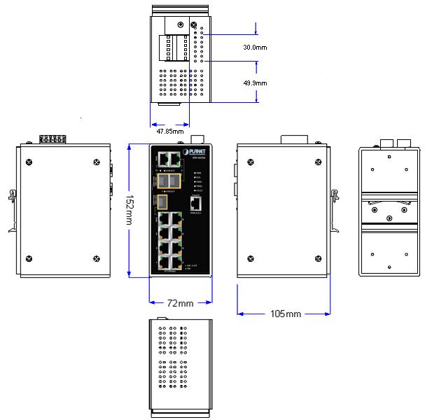
2.1.1 Physical Dimension
ISW-1022M / ISW-1022MT Managed Industrial Switch dimension (W x D x H) : 72mm x 105mm x 152mm
Figure 2-1 ISW-1022M panel layout
18

User’s Manual of ISW-1022M Series and ISW-1033MT
ISW-1022MPT Managed Industrial Switch dimension (W x D x H) : 72mm x 105mm x 152mm
Figure 2-2 ISW-1022MPT panel layout
19
User’s Manual of ISW-1022M Series and ISW-1033MT
ISW-1033MT Managed Industrial Switch dimension (W x D x H) : 72mm x 105mm x 152mm
Figure 2-3 ISW-1033MT panel layout
20
User’s Manual of ISW-1022M Series and ISW-1033MT
2.1.2 Front / Rear Panel
The Front Panel and Rear Panel of the ISW-1022M / ISW-1022MT Managed Industrial Switch are shown as below:
Figure 2-4 Front and Rear Panel of ISW-1022M
1. |
Model Name |
9. 10/100/1000Base-T port |
|
2. System Power: LED |
10. |
1000Base-SX/LX SFP slot |
|
3. |
Ring Master: LED indicator |
11. LED indicators for 1000Base-SX/LX ort |
|
4. |
LED for power 1 input |
12. |
6-Pin Terminal Block |
5. |
LED for power 2 input |
13. |
Ground Screw |
6. |
FAULT: LED indicator |
14. |
Screw holes for Wall Mounting kit |
7. |
RJ-45 type RS-232 Console |
15. |
DIN-Rail Kit |
8. |
8 x 10/100Base-TX port |
|
|
21
User’s Manual of ISW-1022M Series and ISW-1033MT
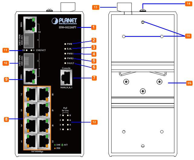
The Front Panel and Rear Panel of the ISW-1022MPT Managed Industrial Switch are shown as below:
Figure 2-5 Front and Rear Panel of ISW-1022MPT
1. |
Model Name |
9. 10/100/1000Base-T port |
|
2. System Power: LED |
10. |
1000Base-SX/LX SFP slot |
|
3. |
Ring Master: LED indicator |
11. LED indicators for 1000Base-SX/LX ort |
|
4. |
LED for power 1 input |
12. |
LED indicators for PoE power output |
5. |
LED for power 2 input |
13. |
6-Pin Terminal Block |
6. |
FAULT: LED indicator |
14. |
Ground Screw |
7. |
RJ-45 type RS-232 Console |
15. |
Screw holes for Wall Mounting kit |
8. |
8 x 10/100Base-TX PoE port |
16. |
DIN-Rail Kit |
22

User’s Manual of ISW-1022M Series and ISW-1033MT
The Front Panel and Rear Panel of the ISW1033MT Managed Industrial Switch are shown as below:
Figure 2-6 Front and Rear Panel of ISW-1033MT
1. |
Model Name |
9. 1000Base-SX/LX SFP slot (Port-7) |
|
2. |
System Power: LED |
10. |
1000Base-SX/LX SFP slots (Port-9 / Port-10) |
3. |
Ring Master: LED indicator |
11. 10/100/1000Base-T ports (Port-9 / Port-10) |
|
4. |
LED for power 1 input |
12. |
6-Pin Terminal Block |
5. |
LED for power 2 input |
13. |
Ground Screw |
6. |
FAULT: LED indicator |
14. |
Screw holes for Wall Mounting kit |
7. |
RJ-45 type RS-232 Console |
15. |
DIN-Rail Kit |
8. |
8 x 10/100Base-TX port |
|
|
23
User’s Manual of ISW-1022M Series and ISW-1033MT
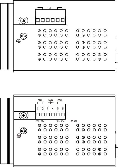
2.1.3 Top View
The top panel of the ISW-1022M series Managed Industrial Switch has one terminal block connector of two DC power
inputs and one fault alarm.
Figure 2-7 Top Panel of ISW-1022M / ISW-1022MT
Figure 2-7 Top Panel of ISW-1022MPT
24

User’s Manual of ISW-1022M Series and ISW-1033MT
The top panel of the ISW-1033MT Managed Industrial Switch has one terminal block connector of two DC power inputs and one fault alarm. The other one terminal block is used for DIDO.
Figure 2-7 Top Panel of ISW-1033MT
2.1.4 LED Indicators
The diagnostic LEDs that provide real-time information of system and optional status are located on the front panel of the ISW-1022M series. The following table provides the description of the LED status and their meanings for the Managed Industrial Switch.
ISW-1022M / ISW-1022MT LED Indicators
System
|
LED |
|
Color |
|
Status |
Meaning |
|
|
|
|
|
On |
The switch unit is power on. |
|
PWR |
|
Green |
|
|
|
|
|
|
Off |
No power. |
||
|
|
|
|
|
||
|
|
|
|
|
|
|
|
|
|
|
|
On |
The industrial switch is the master of X-Ring group. |
|
R.M. |
|
Green |
|
|
|
|
|
|
Off |
The industrial switch is not a ring master in X-Ring group. |
||
|
|
|
|
|
||
|
|
|
|
|
|
|
|
|
|
|
|
On |
Power 1 is active. |
|
PWR1 |
|
Green |
|
|
|
|
|
|
Off |
Power 1 is inactive. |
||
|
|
|
|
|
||
|
|
|
|
|
|
|
|
|
|
|
|
On |
Power 2 is active. |
|
PWR2 |
|
Green |
|
|
|
|
|
|
Off |
Power 2 is inactive. |
||
|
|
|
|
|
||
|
|
|
|
|
|
|
|
|
|
|
|
On |
Power or port failure. |
|
FAULT |
|
Red |
|
|
|
|
|
|
Off |
No failure. |
||
|
|
|
|
|
||
|
|
|
|
|
|
|
25

|
|
|
|
|
|
|
User’s Manual of ISW-1022M Series and ISW-1033MT |
|||
10/100Base-TX Ports – Port-1 to Port-8 |
||||||||||
|
|
|
|
|
|
|
|
|
|
|
|
|
LED |
|
Color |
|
Status |
|
|
Meaning |
|
|
|
|
|
|
|
On |
|
A network device is detected. |
|
|
|
|
|
|
|
|
|
|
|
|
|
|
|
|
|
Green |
|
Blinking |
|
|
The port is transmitting or receiving packets from the TX |
|
|
|
|
|
|
|
|
device. |
|
||
|
|
Port-1 ~ |
|
|
|
Off |
|
No device attached. |
|
|
|
|
Port-8 |
|
|
|
|
|
|
|
|
|
|
|
|
|
On |
|
The port is operating in full-duplex mode. |
|
||
|
|
|
|
Amber |
|
|
|
|
|
|
|
|
|
|
|
Blinking |
|
|
Collision of Packets occurs. |
|
|
|
|
|
|
|
|
|
|
|
|
|
|
|
|
|
|
|
Off |
|
The port is in half-duplex mode or no device is attached. |
|
|
|
|
|
|
|
|
|||||
10/100/1000Base-T / SFP combo interface - Port-9, Port-10 |
||||||||||
|
|
|
|
|
|
|
|
|
|
|
|
|
LED |
|
Color |
|
Status |
|
|
Meaning |
|
|
|
|
|
Green |
|
On |
|
|
A network device is detected. |
|
|
|
|
|
|
|
|
|
|
|
|
|
|
|
|
|
Blinking |
|
|
The port is transmitting or receiving packets from the TX |
|
|
|
|
|
|
(Upper LED) |
|
|
|
|
||
|
|
|
|
|
|
|
device. |
|
||
|
|
Port 9, Port 10 |
|
|
|
|
|
|
||
|
|
|
|
|
Off |
|
|
No device attached |
|
|
|
|
(RJ-45) |
|
|
|
|
|
|
||
|
|
|
|
Green |
|
On |
|
|
1000M |
|
|
|
|
|
(Lower LED) |
|
|
|
|
|
|
|
|
|
|
|
Off |
|
10/100M |
|
||
|
|
|
|
|
|
|
|
|||
|
|
|
|
|
|
|
|
|
|
|
|
|
Link/Active |
|
|
|
On |
|
|
The SFP port is linking |
|
|
|
|
|
|
|
|
|
|
|
|
|
|
|
Green |
|
Blinking |
|
|
The port is transmitting or receiving packets from the TX |
|
|
|
|
(P9, P10 SFP) |
|
|
|
|
|
|||
|
|
|
|
|
|
|
device. |
|
||
|
|
|
|
|
|
|
|
|
||
|
|
|
|
|
|
Off |
|
No device attached |
|
|
|
|
|
|
|
|
|
|
|
|
|
ISW-1033MT LED Indicators
System
|
LED |
|
Color |
|
Status |
Meaning |
|
|
|
|
|
On |
The switch unit is power on. |
|
PWR |
|
Green |
|
|
|
|
|
|
Off |
No power. |
||
|
|
|
|
|
||
|
|
|
|
|
|
|
|
|
|
|
|
On |
The industrial switch is the master of X-Ring group. |
|
R.M. |
|
Green |
|
|
|
|
|
|
Off |
The industrial switch is not a ring master in X-Ring group. |
||
|
|
|
|
|
||
|
|
|
|
|
|
|
26
|
|
|
|
|
|
|
User’s Manual of ISW-1022M Series and ISW-1033MT |
|||
|
|
|
|
|
|
|
|
|
|
|
|
|
PWR1 |
|
Green |
|
On |
|
|
Power 1 is active. |
|
|
|
|
|
|
|
|
|
|
||
|
|
Off |
|
Power 1 is inactive. |
|
|||||
|
|
|
|
|
|
|
|
|||
|
|
|
|
|
|
|
|
|
|
|
|
|
|
|
|
|
On |
|
|
Power 2 is active. |
|
|
|
PWR2 |
|
Green |
|
|
|
|
|
|
|
|
Off |
|
Power 2 is inactive. |
|
|||||
|
|
|
|
|
|
|
|
|||
|
|
|
|
|
|
|
|
|
|
|
|
|
|
|
|
|
On |
|
|
Power or port failure. |
|
|
|
FAULT |
|
Red |
|
|
|
|
|
|
|
|
Off |
|
No failure. |
|
|||||
|
|
|
|
|
|
|
|
|||
|
|
|
|
|
|
|
|
|
|
|
10/100Base-TX Ports – Port-1 to Port-6 and Port-8 |
||||||||||
|
|
|
|
|
|
|
|
|
|
|
|
|
LED |
|
Color |
|
Status |
|
|
Meaning |
|
|
|
|
|
|
|
On |
|
A network device is detected. |
|
|
|
|
|
|
|
|
|
|
|
|
|
|
|
|
|
Green |
|
Blinking |
|
|
The port is transmitting or receiving packets from the TX |
|
|
|
|
|
|
|
|
device. |
|
||
|
|
Port-1 ~ 6 & |
|
|
|
Off |
|
No device attached. |
|
|
|
|
Port-8 |
|
|
|
|
|
|
|
|
|
|
|
|
|
On |
|
The port is operating in full-duplex mode. |
|
||
|
|
|
|
Amber |
|
|
|
|
|
|
|
|
|
|
|
Blinking |
|
|
Collision of Packets occurs. |
|
|
|
|
|
|
|
|
|
|
|
|
|
|
|
|
|
|
|
Off |
|
The port is in half-duplex mode or no device is attached. |
|
|
|
|
|
|
|
|
|||||
10/100/1000Base-T / SFP combo interface - Port-7, Port-9 and Port-10 |
||||||||||
|
|
|
|
|
|
|
|
|
|
|
|
|
LED |
|
Color |
|
Status |
|
|
Meaning |
|
|
|
|
|
Green |
|
On |
|
|
A network device is detected. |
|
|
|
|
|
|
|
|
|
|
|
|
|
|
|
|
|
Blinking |
|
|
The port is transmitting or receiving packets from the TX |
|
|
|
|
Port 7, Port 9, |
|
(Upper LED) |
|
|
|
|
||
|
|
|
|
|
|
device. |
|
|||
|
|
|
|
|
|
|
|
|||
|
|
Port 10 |
|
|
|
Off |
|
|
No device attached |
|
|
|
(RJ-45) |
|
|
|
|
|
|
||
|
|
|
|
|
|
|
|
|
|
|
|
|
|
Green |
|
On |
|
|
1000M |
|
|
|
|
|
|
|
|
|
|
|||
|
|
|
|
(Lower LED) |
|
|
|
|
|
|
|
|
|
|
|
Off |
|
10/100M |
|
||
|
|
|
|
|
|
|
|
|||
|
|
|
|
|
|
|
|
|
|
|
|
|
Link/Active |
|
|
|
On |
|
|
The SFP port is linking |
|
|
|
(P7, P9, P10 |
|
Green |
|
Blinking |
|
|
The port is transmitting or receiving packets from the TX |
|
|
|
SFP) |
|
|
|
|
|
device. |
|
|
|
|
|
|
|
|
|
|
|
||
|
|
|
|
|
Off |
|
No device attached |
|
||
|
|
|
|
|
|
|
|
|||
|
|
|
|
|
|
|
|
|
|
|
27

User’s Manual of ISW-1022M Series and ISW-1033MT
ISW-1022MPT LED Indicators
System
|
LED |
|
Color |
|
Status |
Meaning |
|
|
|
|
|
On |
The switch unit is power on. |
|
PWR |
|
Green |
|
|
|
|
|
|
Off |
No power. |
||
|
|
|
|
|
||
|
|
|
|
|
|
|
|
|
|
|
|
On |
The industrial switch is the master of X-Ring group. |
|
R.M. |
|
Green |
|
|
|
|
|
|
Off |
The industrial switch is not a ring master in X-Ring group. |
||
|
|
|
|
|
||
|
|
|
|
|
|
|
|
|
|
|
|
On |
Power 1 is active. |
|
PWR1 |
|
Green |
|
|
|
|
|
|
Off |
Power 1 is inactive. |
||
|
|
|
|
|
||
|
|
|
|
|
|
|
|
|
|
|
|
On |
Power 2 is active. |
|
PWR2 |
|
Green |
|
|
|
|
|
|
Off |
Power 2 is inactive. |
||
|
|
|
|
|
||
|
|
|
|
|
|
|
|
|
|
|
|
On |
Power or port failure. |
|
FAULT |
|
Red |
|
|
|
|
|
|
Off |
No failure. |
||
|
|
|
|
|
||
|
|
|
|
|
|
|
10/100Base-TX Ports – Port-1 to Port-8
|
LED |
|
Color |
|
Status |
Meaning |
|
|
|
|
|
On |
A network device is detected. |
|
|
|
|
|
|
|
|
|
|
Green |
|
Blinking |
The port is transmitting or receiving packets from the TX |
|
|
|
|
device. |
||
|
Port-1 ~ |
|
|
|
Off |
No device attached. |
|
Port-8 |
|
|
|
|
|
|
|
|
|
On |
The port is operating in full-duplex mode. |
|
|
|
|
Amber |
|
|
|
|
|
|
|
Blinking |
Collision of Packets occurs. |
|
|
|
|
|
|
|
|
|
|
|
|
|
Off |
The port is in half-duplex mode or no device is attached. |
|
|
|
|
|
|
|
PoE port link – Port-1 to Port-8
|
LED |
|
Color |
|
Status |
Meaning |
|
FWD |
|
Green |
|
On |
An IEEE 802.3af PoE power device is detected. |
|
(P1 to P8) |
|
|
|
|
|
|
|
|
|
Off |
No IEEE 802.3af PoE power device attached |
|
|
|
|
|
|
||
|
|
|
|
|
|
|
28
User’s Manual of ISW-1022M Series and ISW-1033MT
10/100/1000Base-T / SFP combo interface - Port-9, Port-10
|
LED |
|
Color |
|
Status |
|
Meaning |
|
|
|
Green |
|
On |
|
A network device is detected. |
|
|
|
|
|
|
|
|
|
|
|
|
Blinking |
|
The port is transmitting or receiving packets from the TX |
|
|
|
|
(Upper LED) |
|
|
||
|
|
|
|
|
device. |
||
|
Port 9, Port 10 |
|
|
|
|
||
|
|
|
|
Off |
|
No device attached |
|
|
(RJ-45) |
|
|
|
|
||
|
|
|
Green |
|
On |
|
1000M |
|
|
|
(Lower LED) |
|
|
|
|
|
|
|
|
Off |
10/100M |
||
|
|
|
|
|
|||
|
|
|
|
|
|
|
|
|
Link/Active |
|
|
|
On |
|
The SFP port is linking |
|
|
|
|
|
|
|
|
|
|
Green |
|
Blinking |
|
The port is transmitting or receiving packets from the TX |
|
|
(P9, P10 SFP) |
|
|
|
|||
|
|
|
|
|
device. |
||
|
|
|
|
|
|
||
|
|
|
|
|
Off |
No device attached |
|
|
|
|
|
|
|
|
|
29

User’s Manual of ISW-1022M Series and ISW-1033MT
2.2 Install the Switch
This section describes how to install your Managed Industrial Switch and make connections to the Managed Industrial Switch. Please read the following topics and perform the procedures in the order being presented. To install your switch on a desktop or shelf, simply complete the following steps.
In this paragraph, we will describe how to install the 8 10/100TX w/ Ring Managed Industrial Switch and the installation points attended to it.
2.2.1Installation Steps
1.Unpack the Industrial switch
2.Check if the DIN-Rail is screwed on the Industrial switch or not. If the DIN-Rail is not screwed on the Industrial switch, please refer to DIN-Rail Mounting section for DIN-Rail installation. If users want to wall mount the Industrial switch, please refer to Wall Mount Plate Mounting section for wall mount plate installation.
3.To hang the Industrial switch on the DIN-Rail track or wall.
4.Power on the Industrial switch. Please refer to the Wiring the Power Inputs section for knowing the information about how to wire the power. The power LED on the Industrial switch will light up. Please refer to the LED Indicators section for indication of LED lights.
5.Prepare the twisted-pair, straight through Category 5 cable for Ethernet connection.
6.Insert one side of RJ-45 cable (category 5) into the Industrial switch Ethernet port (RJ-45 port) and another side of RJ-45 cable (category 5) to the network device’s Ethernet port (RJ-45 port), ex: Switch PC or Server. The UTP port (RJ-45) LED on the Industrial switch will light up when the cable is connected with the network device. Please refer to the LED Indicators section for LED light indication.
Make sure that the connected network devices support MDI/MDI-X. If it does not support,
use the crossover category-5 cable.
7.When all connections are set and LED lights all show in normal, the installation is complete.
30
Loading...