


 Loading...
User’s Manual
WGSW-2620HP
24-Port 10/100Mbps + 2 Gigabit TP/SFP Managed 802.3at PoE Switch

User’s Manual of WGSW-2620HP
Trademarks
Copyright © PLANET Technology Corp. 2011. Contents subject to which revision without prior notice.
PLANET is a registered trademark of PLANET Technology Corp. All other trademarks belong to their respective owners.
Disclaimer
PLANET Technology does not warrant that the hardware will work properly in all environments and applications, and makes no warranty and representation, either implied or expressed, with respect to the quality, performance, merchantability, or fitness for a particular purpose.
PLANET has made every effort to ensure that this User's Manual is accurate; PLANET disclaims liability for any inaccuracies or omissions that may have occurred.
Information in this User's Manual is subject to change without notice and does not represent a commitment on the part of PLANET. PLANET assumes no responsibility for any inaccuracies that may be contained in this User's Manual. PLANET makes no commitment to update or keep current the information in this User's Manual, and reserves the right to make improvements to this User's Manual and/or to the products described in this User's Manual, at any time without notice.
If you find information in this manual that is incorrect, misleading, or incomplete, we would appreciate your comments and suggestions.
FCC Warning
This equipment has been tested and found to comply with the limits for a Class A digital device, pursuant to Part 15 of the FCC Rules. These limits are designed to provide reasonable protection against harmful interference when the equipment is operated in a commercial environment. This equipment generates, uses, and can radiate radio frequency energy and, if not installed and used in accordance with the Instruction manual, may cause harmful interference to radio communications. Operation of this equipment in a residential area is likely to cause harmful interference in which case the user will be required to correct the interference at whose own expense.
CE Mark Warning
This is a Class A product. In a domestic environment, this product may cause radio interference, in which case the user may be required to take adequate measures.
Energy Saving Note of the Device
This power required device does not support Standby mode operation.
For energy saving, please remove the power cable to disconnect the device from the power circuit.
Without removing power cable, the device will still consuming power from the power source. In the view of Saving the Energy and reduce the unnecessary power consuming, it is strongly suggested to remove the power connection for the device if this device is not intended to be active.
WEEE Warning
To avoid the potential effects on the environment and human health as a result of the presence of hazardous substances in electrical and electronic equipment, end users of electrical and electronic equipment should understand the meaning of the crossed-out wheeled bin symbol. Do not dispose of WEEE as unsorted municipal waste and have to collect such WEEE separately.
Revision
PLANET 24-Port 10/100Mbps + 2 Gigabit TP/SFP Managed 802.3at PoE Switch User’s Manual FOR MODEL: WGSW-2620HP
REVISION: 1.0 (MARCH.2011)
Part No.: EM-WGSW-2620HP (2080-A92480-000)
2
|
|
User’s Manual of WGSW-2620HP |
|
TABLE OF CONTENTS |
|
1. INTRODUCTION .......................................................................................................... |
8 |
|
1.1 |
Package Contents ................................................................................................................................ |
8 |
1.2 |
Product Description............................................................................................................................. |
9 |
1.3 How to Use This Manual................................................................................................................... |
11 |
|
1.4 |
Product Features............................................................................................................................... |
12 |
1.5 |
Product Specification ....................................................................................................................... |
14 |
2. INSTALLATION.......................................................................................................... |
16 |
|
2.1 |
Hardware Description ....................................................................................................................... |
16 |
|
2.1.1 Switch Front Panel .................................................................................................................... |
16 |
|
2.1.2 LED Indications.......................................................................................................................... |
17 |
|
2.1.3 Switch Rear Panel ..................................................................................................................... |
19 |
2.2 |
Install the Switch............................................................................................................................... |
20 |
|
2.2.1 Desktop Installation ................................................................................................................... |
20 |
|
2.2.2 Rack Mounting........................................................................................................................... |
21 |
|
2.2.3 Installing the SFP transceiver.................................................................................................... |
22 |
3. SWITCH MANAGEMENT........................................................................................... |
24 |
|
3.1 |
Requirements .................................................................................................................................... |
24 |
3.2 Management Access Overview ....................................................................................................... |
25 |
|
3.3 Web Management.............................................................................................................................. |
26 |
|
3.4 SNMP-Based Network Management ............................................................................................... |
27 |
|
3.5 |
Administration Console.................................................................................................................... |
27 |
3.6 |
Protocols............................................................................................................................................ |
29 |
|
3.6.1 Virtual Terminal Protocols ......................................................................................................... |
29 |
|
3.6.2 SNMP Protocol .......................................................................................................................... |
29 |
|
3.6.3 Management Architecture ......................................................................................................... |
29 |
4. WEB-BASED MANAGEMENT................................................................................... |
30 |
|
4.1 About Web-based Management ...................................................................................................... |
30 |
|
|
4.1.1 Requirements ............................................................................................................................ |
31 |
|
4.1.2 Logging on the Managed Switch ............................................................................................... |
31 |
|
4.1.3 Main WEB PAGE....................................................................................................................... |
33 |
4.2 |
System................................................................................................................................................ |
35 |
|
4.2.1 System Information.................................................................................................................... |
36 |
|
4.2.2 IP Configuration......................................................................................................................... |
39 |
3
|
User’s Manual of WGSW-2620HP |
4.2.3 Console Port Info....................................................................................................................... |
41 |
4.2.4 SNMP Configuration.................................................................................................................. |
42 |
4.2.5 Syslong Setting.......................................................................................................................... |
50 |
4.2.6 System Log................................................................................................................................ |
51 |
4.2.7 SNTP Setting............................................................................................................................. |
52 |
4.2.8 Firmware Upgrade..................................................................................................................... |
53 |
4.2.9 Configuration Backup ................................................................................................................ |
55 |
4.2.10 Factory Default ........................................................................................................................ |
57 |
4.2.11 System Reboot ........................................................................................................................ |
57 |
4.3 Port Configuration ............................................................................................................................ |
58 |
4.3.1 Port Control................................................................................................................................ |
58 |
4.3.2 Rate Control............................................................................................................................... |
60 |
4.3.3 Port Status ................................................................................................................................. |
61 |
4.3.4 Port Statistics............................................................................................................................. |
62 |
4.3.5 Port Sniffer................................................................................................................................. |
63 |
4.3.6 Protect Port................................................................................................................................ |
65 |
4.4 VLAN configuration .......................................................................................................................... |
66 |
4.4.1 VLAN Overview ......................................................................................................................... |
66 |
4.4.2 Static VLAN Configuration......................................................................................................... |
69 |
4.4.3 Port-based VLAN....................................................................................................................... |
70 |
4.4.4 802.1Q VLAN............................................................................................................................. |
72 |
4.4.5 GVRP VLAN .............................................................................................................................. |
78 |
4.4.6 Q-in-Q VLAN.............................................................................................................................. |
81 |
4.5 Trunking............................................................................................................................................. |
85 |
4.5.1 Aggregator setting ..................................................................................................................... |
86 |
4.5.2 Aggregator Information.............................................................................................................. |
87 |
4.5.3 State Activity.............................................................................................................................. |
91 |
4.6 Forwarding and Filtering.................................................................................................................. |
92 |
4.6.1 Dynamic MAC Table.................................................................................................................. |
92 |
4.6.2 Static MAC Table....................................................................................................................... |
93 |
4.6.3 MAC Filtering............................................................................................................................. |
94 |
4.7 IGMP Snooping ................................................................................................................................. |
95 |
4.7.1 Theory........................................................................................................................................ |
95 |
4.7.2 IGMP Configuration ................................................................................................................... |
99 |
4.8 Spanning Tree Protocol.................................................................................................................. |
100 |
4.8.1 Theory...................................................................................................................................... |
100 |
4
|
User’s Manual of WGSW-2620HP |
4.8.2 Illustration of STP .................................................................................................................... |
103 |
4.8.3 STP Parameters ...................................................................................................................... |
104 |
4.8.4 STP System Configuration ...................................................................................................... |
106 |
4.8.5 Port Configuration.................................................................................................................... |
109 |
4.9 DHCP Relay & Option 82 ................................................................................................................ |
111 |
4.10 LLDP............................................................................................................................................... |
113 |
4.10.1 Port Configuration.................................................................................................................. |
113 |
4.10.2 Per Port Configuration ........................................................................................................... |
114 |
4.11 Access Control List ...................................................................................................................... |
115 |
4.12 User Configuration........................................................................................................................ |
119 |
4.13 MAC Limit ...................................................................................................................................... |
120 |
4.13.1 MAC Limit Configuration........................................................................................................ |
120 |
4.13.2 MAC Limit Port Status ........................................................................................................... |
121 |
4.14 802.1X Configuration .................................................................................................................... |
122 |
4.14.1 Understanding IEEE 802.1X Port-Based Authentication ...................................................... |
122 |
4.14.2 System Configuration ............................................................................................................ |
125 |
4.14.3 802.1x Port Configuration...................................................................................................... |
127 |
4.14.4 Misc Configuration................................................................................................................. |
128 |
4.15 QoS Configuration ........................................................................................................................ |
129 |
4.15.1 Understand QoS.................................................................................................................... |
129 |
4.15.2 QoS Configuration ................................................................................................................. |
130 |
4.15.3 TOS/DSCP ............................................................................................................................ |
133 |
4.16 Power over Ethernet ..................................................................................................................... |
136 |
4.16.1 Power over Ethernet Powered Device .................................................................................. |
136 |
4.16.2 WGSW-2620HP Power Management ................................................................................... |
137 |
5. CONSOLE MANAGEMENT ..................................................................................... |
141 |
5.1 Login in the Console Interface ...................................................................................................... |
141 |
5.2 Configure IP address ...................................................................................................................... |
142 |
5.3 Commands Level ............................................................................................................................ |
144 |
6. COMMAND LINE INTERFACE ................................................................................ |
145 |
6.1 Operation Notice ............................................................................................................................. |
145 |
6.2 System Commands......................................................................................................................... |
146 |
6.3 Switch Static Configuration ........................................................................................................... |
147 |
6.3.1 Port Configuration and show status ........................................................................................ |
147 |
6.4 Trunk Configuration........................................................................................................................ |
151 |
6.4.1 Trunking Commands ............................................................................................................... |
151 |
5
|
User’s Manual of WGSW-2620HP |
6.4.2 LACP Command...................................................................................................................... |
152 |
6.5 VLAN Configuration........................................................................................................................ |
154 |
6.5.1 Virtual LANs............................................................................................................................. |
154 |
6.5.2 VLAN Mode: Port-based.......................................................................................................... |
155 |
6.5.3 Advanced 802.1Q VLAN Configuration................................................................................... |
156 |
6.6 Misc Configuration.......................................................................................................................... |
159 |
6.7 Administration Configuration ........................................................................................................ |
160 |
6.7.1 Change Username / Password................................................................................................ |
160 |
6.7.2 IP Configuration....................................................................................................................... |
161 |
6.7.3 Reboot switch .......................................................................................................................... |
162 |
6.7.4 Reset to Default....................................................................................................................... |
162 |
6.7.5 TFTP Update Firmware ........................................................................................................... |
162 |
6.7.6 Restore Configure File............................................................................................................. |
163 |
6.7.7 Backup Configure File ............................................................................................................. |
163 |
6.8 MAC limit.......................................................................................................................................... |
163 |
6.9 Port Mirroring Configuration.......................................................................................................... |
164 |
6.10 Quality of Service.......................................................................................................................... |
166 |
6.10.1 QoS Configuration ................................................................................................................. |
166 |
6.10.2 Per Port Priority ..................................................................................................................... |
167 |
6.11 MAC Address Configuration........................................................................................................ |
168 |
6.12 STP/MSTP Commands.................................................................................................................. |
170 |
6.13 SNMP.............................................................................................................................................. |
177 |
6.13.1 System Options ..................................................................................................................... |
177 |
6.13.2 Community Strings ................................................................................................................ |
178 |
6.13.3 Trap Managers ...................................................................................................................... |
178 |
6.14 IGMP ............................................................................................................................................... |
179 |
6.15 802.1x Protocol.............................................................................................................................. |
181 |
6.16 Access Control List ...................................................................................................................... |
184 |
6.16.1 Ipv4 ACL commands ............................................................................................................. |
184 |
6.16.2 Non-Ipv4 ACL commands ..................................................................................................... |
186 |
6.17 Binding........................................................................................................................................... |
187 |
6.17.1 SIP/SMAC binding commands .............................................................................................. |
187 |
6.18 Power over Ethernet Commands ................................................................................................ |
189 |
6.18.1 Display System PoE status ................................................................................................... |
189 |
6.18.2 Configure PoE Over Temperature Protection ....................................................................... |
191 |
6.18.3 Configure PoE -- System....................................................................................................... |
192 |
6
|
|
User’s Manual of WGSW-2620HP |
|
6.18.4 Configure PoE -- Port ............................................................................................................ |
198 |
7. SWITCH OPERATION.............................................................................................. |
201 |
|
7.1 |
Address Table ................................................................................................................................. |
201 |
7.2 |
Learning ........................................................................................................................................... |
201 |
7.3 |
Forwarding & Filtering.................................................................................................................... |
201 |
7.4 |
Store-and-Forward .......................................................................................................................... |
201 |
7.5 |
Auto-Negotiation ............................................................................................................................. |
202 |
8. POWER OVER ETHERNET OVERVIEW................................................................. |
203 |
|
What is PoE? ......................................................................................................................................... |
203 |
|
The PoE Provision Process ................................................................................................................. |
205 |
|
|
Stages of powering up a PoE link..................................................................................................... |
205 |
|
Line Detection................................................................................................................................... |
205 |
|
Classification..................................................................................................................................... |
205 |
|
Start-up ............................................................................................................................................. |
206 |
|
Operation .......................................................................................................................................... |
206 |
|
Power Disconnection Scenarios....................................................................................................... |
206 |
9. TROUBLE SHOOTING............................................................................................. |
207 |
|
APPENDIX A—RJ-45 PIN ASSIGNMENT ................................................................... |
209 |
|
A.1 Switch's RJ-45 Pin Assignments .................................................................................................. |
209 |
|
A.2 10/100Mbps, 10/100Base-TX.......................................................................................................... |
209 |
|
7
User’s Manual of WGSW-2620HP
1. Introduction
The PLANET Layer 2 Managed Switch – WGSW-2620HP is 24-Port 10/100Mbps + 2 Gigabit TP/SFP Managed 802.3at PoE Switch, with two Gigabit TP/SFP fiber optical combo connective ability and robust layer 2 features; the WGSW-2620HP also provide IEEE 802.3af / IEEE 802.3at Power over Ethernet system to fill further PoE demand and application.
Terms of “Managed Switch” means the Switch mentioned titled in the cover page of this user’s manual, i.e. WGSW-2620HP.
1.1 Package Contents
Open the box of the Managed Switch and carefully unpack it. The box should contain the following items: Check the contents of your package for following parts:
; The Managed Switch |
x1 |
; Quick Installation Guide |
x1 |
; User’s Manual CD |
x1 |
; 19” Rack mount Accessory Kit |
x1 |
; Power Cord |
x1 |
; Rubber Feet |
X4 |
; RS-232 DB9 Male Console Cable |
x1 |
If any of these are missing or damaged, please contact your dealer immediately, if possible, retain the carton including the original packing material, and use them against to repack the product in case there is a need to return it to us for repair.
8
User’s Manual of WGSW-2620HP
1.2 Product Description
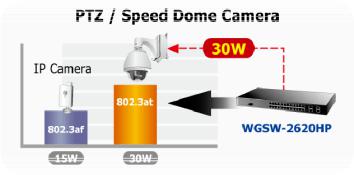
Power over Ethernet
The PoE in-line power following the standard IEEE 802.3af and IEEE 802.3at makes the Managed Switch able to power on 24 IEEE 802.3af PoE devices or 11 IEEE 802.3at PoE devices at the distance up to 100 meters through the 4-pair Cat 5/5e UTP wire.
Flexibility PoE System Management
Managed Switch is not only provides more PoE management function than ever before but also provides better reliability. System PoE Admin Mode feature offers user to switch PoE system mode between IEEE 802.3af and IEEE 802.3at easily and the Temperature Threshold, PoE Usage Threshold provides more exact reliability control.
Cost-effective solution with SNMP monitor for Network deployment
Not only for catering to the need of easy WEB-based management but also the centralized SNMP application to monitor the status of Managed Switch and traffic per port, the key features are as below:
802.3af / 802.3at PoE |
SNMP and 4 RMON groups |
||
WEB / SSL / Telnet |
|
Access Control List |
|
|
802.1Q / Q-in-Q VLAN |
|
IGMP Snooping |
|
Multiple Spanning Tree Protocol |
PoE Management / Alarm |
|
High Performance Wire-Speed Switching
The Managed Switch offers 24 10/100Mbps Fast Ethernet ports with 2 Gigabit TP/SFP combo ports (Port-25, 26). The two Gigabit TP/SFP combo ports can be either 1000Base-T for 10/100/1000Mbps or 1000Base-SX/LX through SFP (Small Form-Factor Pluggable) interface. Managed Switch boasts a high performance switch architecture that is capable of providing non-blocking switch fabric and wire-speed throughput as high as 8.8Gbps. Its two built-in GbE uplink ports also offer incredible extensibility, flexibility and connectivity to the Core switch or Servers.
Remote and Centralize Management installation
Afford the current network to grow and expand, the Managed Switch provide advanced WEB and SNMP management interface to fill this kind of demand. With its built-in Web-based management, the Managed Switch offers an easy-to-use, platform-independent management and configuration facility. The Managed Switch supports standard Simple Network Management Protocol (SNMP) and can be monitored via any standard-based management software.
For efficient management, via WEB interface the Managed Switch can be programmed for basic switch management functions such as port speed configuration, Port Trunking, VLAN, Port Mirroring, Rapid Spanning Tree and Misc
9
User’s Manual of WGSW-2620HP
Configuration. Additionally, the firmware includes advanced features such as IGMP snooping, QoS (Quality of Service), broadcast storm and bandwidth control, to enhance bandwidth utilization.
Powerful Security
The Managed Switch offers comprehensive Access Control List (ACL) for enforcing security to the edge. Its protection mechanisms comprises of Port-based 802.1X user and device authentication. Moreover, the switch provides MAC filter and Static MAC for enforcing security policies to the edge. The administrators can now construct highly secured corporate networks with considerably less time and effort than before.
10
User’s Manual of WGSW-2620HP
1.3 How to Use This Manual
This User Manual is structured as follows:
Section 2, INSTALLATION
The section explains the functions of the Switch and how to physically install the Managed Switch.
Section 3, SWITCH MANAGEMENT
The section contains the information about the software function of the Managed Switch.
Section 4, WEB CONFIGURATION
The section explains how to manage the Managed Switch by Web interface.
Section 5, CONSOLE MANAGEMENT
The section describes how to use the Console management interface.
Section 6, COMMAND LINE INTERFACE
The section explains how to manage the Managed Switch by Command Line interface.
Section 7, SWITCH OPERATION
The chapter explains how to does the switch operation of the Managed Switch.
Section 8, POWER OVER ETHERNET OVERVIEW
The chapter introduce the IEEE 802.3af / IEEE 802.3at PoE standard and PoE provision of the Managed Switch.
Section 9, TROUBSHOOTING
The chapter explains how to trouble shooting of the Managed Switch.
Appendix A
The section contains cable information of the Managed Switch.
11

User’s Manual of WGSW-2620HP
1.4 Product Features
Physical Port
24-Port 10/100Base-TX Fast Ethernet ports with IEEE 802.3af / IEEE 802.3at PoE injector
2 10/100/1000Base-T TP combo interfaces
2 1000Base-X mini-GBIC/SFP slots, shared with Port-25 and Port-26
Reset button for system management
1 RS-232 male DB9 console interface for Switch basic management and setup
Power over Ethernet
Complies with IEEE 802.3af / IEEE 802.3at Power over Ethernet End-Span PSE
Up to 24 IEEE 802.3af devices powered
Up to 11 IEEE 802.3at devices powered
Support PoE Power up to 15.4 Watts / 30 Watts for each PoE ports
Auto detect powered device (PD)
Circuit protection prevent power interference between ports
Remote power feeding up to 100m
PoE Management
•IEEE 802.3af and IEEE 802.3at mode switch control
•Total PoE power budget control
•Per port PoE function enable/disable
•PoE Admin-mode control
•PoE Port Power feeding priority
•PD classification detection
•Over Temperature Protection function
•Temperature Threshold Control
•PoE Usage Threshold Control
Layer 2 Features
Prevents packet loss Flow Control:
- IEEE 802.3x PAUSE Frame flow control for Full-Duplex mode - Back-Pressure Flow Control in Half-Duplex mode
High performance of Store-and-Forward architecture, runt/CRC filtering eliminate erroneous packets to optimize the network bandwidth
Broadcast / Multicast / Unicast storm control
8K MAC address table, automatic source address learning and ageing
Supports VLAN
- IEEE 802.1Q Tag-based VLAN - Port-Based VLAN
- Q-in-Q tunneling
- GVRP for dynamic VLAN Management - Private VLAN Edge (PVE / Protect Port )
Supports Link Aggregation
−up to 13 trunk groups
−up to 8 ports per trunk group with 1.6Gbps bandwidth (Full Duplex Mode)
−IEEE 802.3ad LACP (Link Aggregation Control Protocol)
12

User’s Manual of WGSW-2620HP
− Cisco ether-channel (Static Trunk)
Spanning Tree Protocol
- STP, IEEE 802.1D (Classic Spanning Tree Protocol)
- MSTP, IEEE 802.1s (Multiple Spanning Tree Protocol, spanning tree by VLAN)
Port Mirroring to monitor the incoming or outgoing traffic on a particular port
Quality of Service
4 priority queues on all switch ports
Traffic classification:
-IEEE 802.1p CoS
-IP TOS / DSCP to 802.1p priority mapping
-Port-Based priority
Strict priority and Weighted Round Robin (WRR) CoS policies
Supports QoS and In/Out bandwidth control on each port
In/Out rate limit control on each port
Multicast
Supports IGMP Snooping v1 and v2
IGMP Snooping v2 fast leave
Querier mode support
Security
IEEE 802.1x Port-Based network access control protocol
RADIUS users access authentication
L3 / L4 Access Control List (ACL)
Source IP-MAC / Port-Binding
Port Security for Source MAC address entries filtering
Management
Switch Management Interface
- Telnet Command Line Interface - Web switch management
- SNMP v1, v2c, v3 switch management - SSL switch management
Three user privilege levels control (Admin, Operator, viewer)
DHCP client for IP address assignment
DHCP Option82 and DHCP Relay
Link Layer Discovery Protocol (LLDP) for easy network management
Built-in Trivial File Transfer Protocol (TFTP) client
Firmware upgrade via TFTP or HTTP
Configuration restore / backup via TFTP or HTTP
Event message logging to remote Syslog server
Alarm records extractable in standard CSV format for post processing
Four RMON groups 1, 2, 3, 9 (history, statistics, alarms, and events)
SNMP trap / E-Mail Alarm for interface Link Up and Link Down notification
Supports Ping function
Supports Simple Network Protocol (SNTP)
13

User’s Manual of WGSW-2620HP
1.5 Product Specification
|
Product |
WGSW-2620HP |
|
|
24-Port 10/100Mbps + 2 Gigabit TP / SFP Managed 802.3at PoE Switch |
||
|
|
||
|
Hardware Specification |
|
|
|
|
|
|
|
10/100Mbps Copper Ports |
24 10/ 100Base-TX RJ-45 Auto-MDI/MDI-X ports |
|
|
|
|
|
|
1000Mbps Copper Ports |
2 10/100/1000Mbps RJ-45 Auto-MDI/MDI-X ports |
|
|
|
|
|
|
SFP/mini-GBIC Slots |
2 1000Base-SX/LX/BX, shared with Port-25~Port-26 |
|
|
Switch Architecture |
Store-and-Forward |
|
|
Switch Fabric |
8.8Gbps / non-blocking |
|
|
Switch Throughput |
6.547Mpps @64Bytes |
|
|
Address Table |
8K entries |
|
|
Share Data Buffer |
512Kbytes |
|
|
Flash |
4MB |
|
|
DRAM |
32MB |
|
|
Maximum Frame Size |
9K Bytes |
|
|
Flow Control |
Back pressure for Half-Duplex |
|
|
IEEE 802.3x Pause Frame for Full-Duplex |
||
|
|
||
|
|
Power, PoE Power, FAN Alert |
|
|
|
Link/Activity (Green) |
|
|
LED |
PoE In-Use (Amber) |
|
|
|
1000 LNK / ACT(Green) |
|
|
|
10/100 LNK / ACT(Green) |
|
|
Dimensions ( W x D x H) |
440 x 300 x 44.5mm, 1U height |
|
|
Weight |
4.6kg |
|
|
Power Requirement |
100 - 240VAC, 50 - 60Hz, Auto-sensing. |
|
|
|
System: 110V: 29 Watts / 98BTU, 220V: 31 Watts / 105BTU |
|
|
Power Consumption |
Ethernet Full Loading: 110V: 34 Watts / 116BTU, 220V: 35 Watts / 119BTU |
|
|
|
PoE Full Loading: 110V: 360 Watts / 1228BTU, 220V: 360 Watts / 1228BTU |
|
|
Operating Temperature |
0°C ~ 50°C Degree C |
|
|
Operating Humidity |
10% ~ 95% (non-condensing) |
|
|
Storage Temperature |
-20°C ~ 70 Degree C |
|
|
Storage Humidity |
10% ~ 95% (non-condensing) |
|
|
Reset Button |
< 5 sec: System reboot |
|
|
> 10 sec: Factory Default |
||
|
|
||
|
Power over Ethernet |
|
|
|
PoE Standard |
IEEE 802.3af / IEEE 802.3at Power over Ethernet / PSE |
|
|
PoE Power Supply Type |
End-Span |
|
|
PoE Power Output |
Per Port 52V DC, 350mA . Max.15.4 Watts (IEEE 802.3af) |
|
|
Per Port 52V DC, 590mA. Max. 30 Watts (IEEE 802.3at) |
||
|
|
||
|
Power Pin Assignment |
1/2(+), 3/6(-) |
|
|
PoE Power Budget |
360 Watts (Port 1 to port 12: 180 Watts, port 13 to port 24: 180 Watts) |
|
|
Max. number of Class 1 PD |
24 |
|
|
Max. number of Class 2 PD |
24 |
|
|
Max. number of Class 3 PD |
24 |
|
|
Max. number of Class 0, 4 PD |
11 |
|
|
Layer 2 Function |
|
|
|
Management Interface |
Console, Telnet, Web Browser, SSL, SNMPv1, v2c, v3 |
|
|
|
Port disable/enable |
|
|
Port Configuration |
Auto-negotiation |
|
|
10/100/1000Mbps full and half duplex mode selection |
||
|
|
||
|
|
Flow Control disable / enable |
|
|
Port Status |
Display each port’s speed duplex mode, link status and Flow control status. |
|
14
User’s Manual of WGSW-2620HP
|
Auto negotiation status, trunk status. |
||
Port Mirroring |
TX / RX / Both |
|
|
1 to 1 monitor |
|
||
|
|
||
Bandwidth Control |
Ingress / Egress Rate Control |
||
• Allow to configure per 128Kbps |
|||
|
|||
|
IEEE 802.1Q Tag-based VLAN, up to 255 VLANs groups, out of 4041 VLAN IDs |
||
|
Port-based VLAN |
|
|
VLAN |
Q-in-Q tunneling |
|
|
|
GVRP for VLAN Management, up to 128 dynamic VLAN entries |
||
|
Private VLAN Edge(PVE / Protected port) with two protected port groups |
||
|
Static Port Trunk |
|
|
Link Aggregation |
IEEE 802.3ad LACP (Link Aggregation Control Protocol) |
||
|
Supports 13 groups of 8-Port trunk support |
||
|
4 priority queue |
|
|
|
Traffic classification based on: |
||
QoS |
- Port priority |
|
|
|
- 802.1p priority |
||
|
- DSCP/TOS field in IP Packet |
||
IGMP Snooping |
IGMP (v1/v2) Snooping, up to 256 multicast Groups |
||
Access Control List |
IP-Based Layer 3 / Layer 4 ACL |
||
Up to 200 ACL rule entries |
|||
|
|||
|
RFC-1213 MIB-II |
|
|
|
RFC-2863 Interface MIB |
||
|
RFC-2665 EtherLike MIB |
||
SNMP MIBs |
RFC-1493 Bridge MIB |
||
|
RFC-2819 RMON MIB (Group 1, 2, 3,9) |
||
|
RFC-2737 Entity MIB |
||
|
POWER-ETHERNET-MIB |
||
Standards Conformance |
|
|
|
|
IEEE 802.3 |
10Base-T |
|
|
IEEE 802.3u |
100Base-TX |
|
|
IEEE 802.3z |
1000Base-SX/LX |
|
|
IEEE 802.3ab |
1000Base-T |
|
|
IEEE 802.3x |
Flow Control and Back pressure |
|
|
IEEE 802.3ad |
Port trunk with LACP |
|
|
IEEE 802.1D |
Spanning Tree Protocol |
|
|
IEEE 802.1s |
Multiple Spanning Tree Protocol |
|
|
IEEE 802.1p |
Class of Service |
|
Standards Compliance |
IEEE 802.1Q |
VLAN Tagging |
|
IEEE 802.1x |
Port Authentication Network Control |
||
|
|||
|
IEEE 802.3af |
Power over Ethernet |
|
|
IEEE 802.3at |
Power over Ethernet (Pre-Standard) |
|
|
RFC 768 |
UDP |
|
|
RFC 793 |
TFTP |
|
|
RFC 791 |
IP |
|
|
RFC 792 |
ICMP |
|
|
RFC 2068 |
HTTP |
|
|
RFC 1112 |
IGMP version 1 |
|
|
RFC 2236 |
IGMP version 2 |
|
* With total PoE power output be limited at 360 Watts
15

User’s Manual of WGSW-2620HP
2. INSTALLATION
This section describes the hardware features and installation of the Managed Switch on the desktop or rack mount. For easier management and control of the Managed Switch, familiarize yourself with its display indicators, and ports. Front panel illustrations in this chapter display the unit LED indicators. Before connecting any network device to the Managed Switch, please read this chapter completely.
2.1 Hardware Description
2.1.1 Switch Front Panel
The unit front panel provides a simple interface monitoring the switch. Figure 2-1 shows the front panel of the Managed Switches.
WGSW-2620HP Front Panel
Figure 2-1: WGSW-2620HP Front Panel
■ 10/100Mbps TP Interface
Port-1~Port-24: 10/100Base-TX Copper, RJ-45 Twist-Pair: Up to 100 meters.
■ Gigabit TP Interface
Port-25, Port-26: 10/100/1000Base-T Copper, RJ-45 Twist-Pair: up to 100 meters.
■ Gigabit SFP Slots
Port-25, Port-26: 1000Base-SX/LX mini-GBIC slot, SFP (Small Factor Pluggable) transceiver module: From 550 meters (Multi-mode fiber), up to 10/20/30/40/50/70/120 kilometers (Single-mode fiber).
■ Console Port
The console port is a DB9, RS-232 male serial port connector. It is an interface for connecting a terminal directly. Through the console port, it provides rich diagnostic information includes IP Address setting, factory reset, port management, link status and system setting. Users can use the attached RS-232 cable in the package and connect to the console port on the device. After the connection, users an run any terminal emulation program (Hyper Terminal, ProComm Plus, Telix, Winterm and so on) to enter the startup screen of the device.
16

User’s Manual of WGSW-2620HP
■ Reset button
At the left of front panel, the reset button is designed for reboot the Managed Switch without turn off and on the power. The following is the summary table of Reset button functions:
Reset Button Pressed and Released |
Function |
|
About 5 seconds |
Reboot the Managed Switch. |
|
|
|
|
|
Reset the Managed Switch to Factory Default configuration. |
|
|
The Managed Switch will then reboot and load the default |
|
About 10 seconds |
settings as below: |
|
|
Default Password: admin |
|
|
|
Default IP address: 192.168.0.100 |
|
|
Subnet mask: 255.255.255.0 |
|
|
Default Gateway: 192.168.0.254 |
2.1.2 LED Indications
The front panel LEDs indicates instant status of port links, data activity and system power; helps monitor and troubleshoot when needed.
WGSW-2620HP LED indication
|
|
Figure 2-2: WGSW-2620HP LED Panel |
System |
|
|
|
|
|
LED |
Color |
Function |
|
|
|
PWR |
Green |
Lights to indicate that the Switch has power. |
SYS |
Green |
Lights to indicate the system is working. |
Alert |
|
|
|
|
|
LED |
Color |
Function |
|
|
|
PWR Alert |
Green |
Lights to indicate that the PoE power supply failure. |
|
|
|
FAN1 |
Green |
Lights to indicate that the FAN1 failure. |
|
|
|
FAN2 |
Green |
Lights to indicate that the FAN2 failure. |
|
|
|
FAN3 |
Green |
Lights to indicate that the FAN3 failure. |
|
|
|
17

User’s Manual of WGSW-2620HP
Per 10/100Mbps port, PoE interfaces (Port-1 to Por-24)
LED |
Color |
|
Function |
|
|
|
|
LNK/ACT |
Green |
Lights: |
To indicate the link through that port is successfully established. |
|
To indicate that the Switch is actively sending or receiving data over that port. |
||
|
|
Blink: |
|
|
|
|
|
PoE In-Use |
Orange |
Lights: |
To indicate the port is providing 52V DC in-line power. |
|
To indicate the connected device is not a PoE Powered Device (PD). |
||
|
|
Off: |
|
|
|
|
|
Per 10/100/1000Base-T port / SFP interfaces
|
LED |
|
Color |
|
|
Function |
|
|
|
|
|
|
|
|
|
|
|
|
|
|
|
Lights: |
To indicate the link through that port is successfully established with speed |
1000 |
|
|
|
|
|
1000Mbps. |
|
|
|
Green |
|
Blink: |
To indicate that the Switch is actively sending or receiving data over that port. |
||
|
LNK/ACT |
|
|
||||
|
|
|
|
Off: |
If 10/100 LNK/ACT LED is light, it indicates that the port is operating at 10Mbps or |
||
|
|
|
|
|
|
||
|
|
|
|
|
|
|
100Mbps. If LNK/ACT LED is Off, it indicates that the port is link down. |
|
|
|
|
|
|
|
|
|
|
|
|
|
|
Lights: |
To indicate the link through that port is successfully established with speed |
10/100 |
|
|
|
|
|
10Mbps or 100Mbps. |
|
|
|
Green |
|
Blink: |
To indicate that the Switch is actively sending or receiving data over that port. |
||
|
LNK/ACT |
|
|
||||
|
|
|
Off: |
If 1000 LNK/ACT LED is light, it indicates that the port is operating at 1000Mbps. |
|||
|
|
|
|
|
|||
|
|
|
|
|
|
|
If 1000 LNK/ACT LED is Off, it indicates that the port is link down. |
|
|
|
|
|
|
|
|
|
|
|
|
|
|
|
|
1.Press the RESET button 5 seconds. The Managed Switch will reboot automatically.
2.Press the RESET button for about 10 seconds. The Managed Switch will back to the factory default mode; the entire configuration will be erased.
3.The 2 Gigabit TP/SFP combo ports are shared with port 25/26 of Managed Switch. Either of them can operate at the same time.
18
User’s Manual of WGSW-2620HP
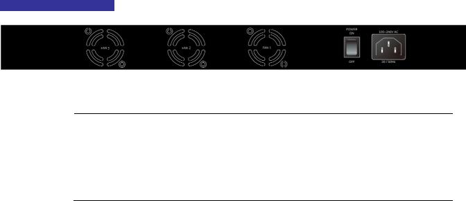
2.1.3 Switch Rear Panel
The rear panel of the Managed Switch indicates an AC inlet power socket, which accepts input power from 100 to 240V AC, 50-60Hz. Figure 2-3 shows the rear panel of the Managed Switch.
WGSW-2620HP Rear Panel
Figure 2-3: WGSW-2620HP Rear Panel.
1.The device is a power-required device, it means, it will not work till it is powered. If your networks should active all the time, please consider using UPS (Uninterrupted Power Supply) for your
Power Notice: device. It will prevent you from network data loss or network downtime.
2.In some area, installing a surge suppression device may also help to protect your Managed Switch from being damaged by unregulated surge or current to the Switch or the power adapter.
19
User’s Manual of WGSW-2620HP
2.2 Install the Switch
This section describes how to install the Managed Switch and make connections to it. Please read the following topics and perform the procedures in the order being presented.
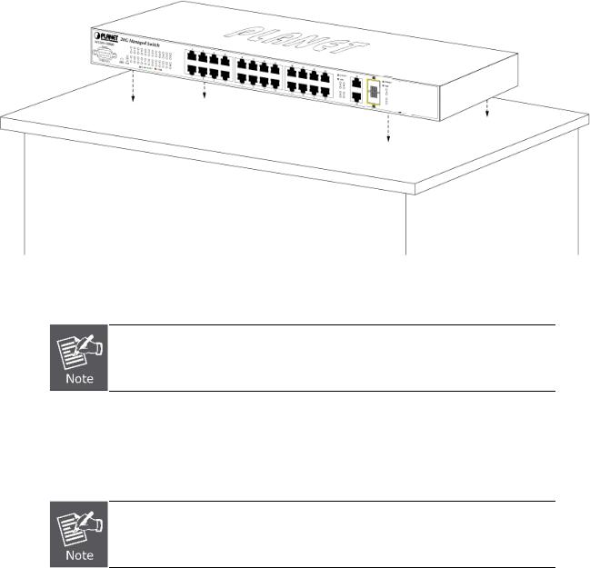
2.2.1 Desktop Installation
To install the Managed Switch on desktop or shelf, please follows these steps:
Step1: Attach the rubber feet to the recessed areas on the bottom of the Managed Switch.
Step2: Place the Managed Switch on the desktop or the shelf near an AC power source.
Figure 2-4: Place the Managed Switch on the desktop
Step3: Keep enough ventilation space between the Managed Switch and the surrounding objects.
When choosing a location, please keep in mind the environmental restrictions discussed in
Chapter 1, Section 4, in Specification.
Step4: Connect the Managed Switch to network devices.
A.Connect one end of a standard network cable to the 10/100/1000 RJ-45 ports on the front of the Managed Switch
B.Connect the other end of the cable to the network devices such as printer servers, workstations or routers…etc.
Connection to the Managed Switch requires UTP Category 5 network cabling with RJ-45 tips. For more information, please see the Cabling Specification in Appendix A.
Step5: Supply power to the Managed Switch.
A.Connect one end of the power cable to the Managed Switch.
B.Connect the power plug of the power cable to a standard wall outlet.
When the Managed Switch receives power, the Power LED should remain solid Green.
20
User’s Manual of WGSW-2620HP
2.2.2 Rack Mounting
To install the Managed Switch in a 19-inch standard rack, please follows the instructions described below.
Step1: Place the Managed Switch on a hard flat surface, with the front panel positioned towards the front side.
Step2: Attach the rack-mount bracket to each side of the Managed Switch with supplied screws attached to the package. Figure 2-5 shows how to attach brackets to one side of the Managed Switch.
Figure 2-5: Attach brackets to the Managed Switch
You must use the screws supplied with the mounting brackets. Damage caused to the parts by using incorrect screws would invalidate the warranty.
Step3: Secure the brackets tightly.
Step4: Follow the same steps to attach the second bracket to the opposite side.
Step5: After the brackets are attached to the Managed Switch, use suitable screws to securely attach the brackets to the rack, as shown in Figure 2-6.
Figure 2-6: Mounting the Switch in a Rack
Step6: Proceeds with the steps 4 and steps 5 of session 2.2.1 Desktop Installation to connect the network cabling and supply power to the Managed Switch.
21
User’s Manual of WGSW-2620HP
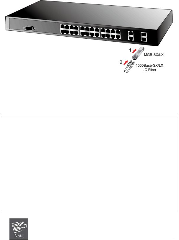
2.2.3 Installing the SFP transceiver
The sections describe how to insert an SFP transceiver into an SFP slot.
The SFP transceivers are hot-pluggable and hot-swappable. You can plug-in and out the transceiver to/from any SFP port without having to power down the Managed Switch. As the Figure 2-7appears.
Figure 2-7: Plug-in the SFP transceiver
Approved PLANET SFP Transceivers
PLANET Managed switch supports both single mode and multi mode SFP transceiver. The following list of approved PLANET SFP transceivers is correct at the time of publication:
1000Base-SX/LX SFP transceiver:
PLANET SFP Module List
|
Model |
|
Interface |
Speed |
Fiber connector and distance |
Operating |
|
|
|
Temperature |
|||||
|
|
|
|
|
|
||
|
MGB-GT |
|
1000Base-T |
1000Mbps |
RJ-45 – 100m |
0 ~50 |
|
|
|
|
|
|
|
|
|
|
MGB-SX |
|
1000Base-SX |
1000Mbps |
LC, Multi-Mode (850nm) -220m/550m |
0 ~50 |
|
|
|
|
|
|
|
|
|
|
MGB-SX2 |
|
1000Base-SX |
1000Mbps |
LC, Multi-Mode (1310nm) -2km |
0 ~50 |
|
|
|
|
|
|
|
|
|
|
MGB-LX |
|
1000Base-LX |
1000Mbps |
LC, Single Mode (1310nm) – 10km |
0 ~50 |
|
|
|
|
|
|
|
|
|
|
MGB-L30 |
|
1000Base-LX |
1000Mbps |
LC, Single Mode (1310nm) – 30km |
0 ~50 |
|
|
|
|
|
|
|
|
|
|
MGB-L50 |
|
1000Base-LX |
1000Mbps |
LC, Single Mode (1310nm) – 50km |
0 ~50 |
|
|
|
|
|
|
|
|
|
|
MGB-L70 |
|
1000Base-LX |
1000Mbps |
LC, Single Mode (1550nm) – 70km |
0 ~50 |
|
|
|
|
|
|
|
|
|
|
MGB-L120 |
|
1000Base-LX |
1000Mbps |
LC, Single Mode (1550nm) – 120km |
0 ~50 |
|
|
|
|
|
|
|
|
|
|
|
|
|
|
|
|
|
It recommends using PLANET SFPs on the Switch. If you insert a SFP transceiver that is
not supported, the Managed Switch will not recognize it.
22

User’s Manual of WGSW-2620HP
Before connect the other switches, workstation or Media Converter.
1.Make sure both side of the SFP transceiver are with the same media type, for example: 1000Base-SX to 1000Base-SX, 1000Bas-LX to 1000Base-LX.
2.Check the fiber-optic cable type match the SFP transceiver model.
¾To connect to 1000Base-SX SFP transceiver, use the multi-mode fiber cablewith one side must be male duplex LC connector type.
¾To connect to 1000Base-LX SFP transceiver, use the single-mode fiber cable-with one side must be male duplex LC connector type.
Connect the fiber cable
1.Attach the duplex LC connector on the network cable into the SFP transceiver.
2.Connect the other end of the cable to a device – switches with SFP installed, fiber NIC on a workstation or a Media Converter.
3.Check the LNK/ACT LED of the SFP slot on the front of the Managed Switch. Ensure that the SFP transceiver is operating correctly.
4.Check the Link mode of the SFP port if the link failed. Co works with some fiber-NICs or Media Converters, set the Link mode to “1000 Force” is needed.
Remove the transceiver module
1.Make sure there is no network activity by consult or check with the network administrator. Or through the management interface of the switch/converter (if available) to disable the port in advance.
2.Remove the Fiber Optic Cable gently.
3.Turn the handle of the MGB module to horizontal.
4.Pull out the module gently through the handle.
Figure 2-8: Pull out the SFP transceiver
Never pull out the module without pull the handle or the push bolts on the module. Direct pull out the module with violent could damage the module and SFP module slot of the Managed Switch.
23

User’s Manual of WGSW-2620HP
3. SWITCH MANAGEMENT
This chapter explains the methods that you can use to configure management access to the Managed Switch. It describes the types of management applications and the communication and management protocols that deliver data between your management device (work-station or personal computer) and the system. It also contains information about port connection options.
This chapter covers the following topics:
Requirements
Management Access Overview
Administration Console Access
Web Management Access
SNMP Access
Standards, Protocols, and Related Reading
3.1Requirements
The operate system of subscriber PC that running Windows XP/2003, Vista, Windows 7, MAC OS X , Linux, Fedora, Ubuntu or other platform compatible with TCP/IP protocols.
Workstation installed with Ethernet NIC (Network Interface Card)
Ethernet Port connect
•Network cables - Use standard network (UTP) cables with RJ45 connectors.
Above Workstation installed with WEB Browser and JAVA runtime environment Plug-in
Serial Port connect
•Above PC with COM Port (DB-9 / RS-232) or USB-to-RS-232 converter
It is recommended to use Internet Explore 6.0 or above to access Managed Switch.
24
User’s Manual of WGSW-2620HP
3.2 Management Access Overview
The Managed Switch gives you the flexibility to access and manage it using any or all of the following methods:
Web browser interface
An external SNMP-based network management application
An administration console
The administration console and Web browser interface support are embedded in the Managed Switch software and are available for immediate use. Each of these management methods has their own advantages. Table 3-1 compares the three management methods.
Method |
|
Advantages |
Disadvantages |
Web Browser |
• |
Ideal for configuring the switch remotely |
• Security can be compromised (hackers need |
|
• |
Compatible with all popular browsers |
only know the IP address and subnet mask) |
|
• |
Can be accessed from any location |
• May encounter lag times on poor connections |
|
• |
Most visually appealing |
|
|
|
|
|
SNMP Agent |
• |
Communicates with switch functions at |
• Requires SNMP manager software |
|
|
the MIB level |
• Least visually appealing of all three methods |
|
• |
Based on open standards |
• Some settings require calculations |
|
|
|
• Security can be compromised (hackers need |
|
|
|
only know the community name) |
|
|
|
|
Console |
• |
No IP address or subnet needed |
• Must be near switch or use dial-up connection |
|
• |
Text-based |
• Not convenient for remote users |
|
• |
Telnet functionality and HyperTerminal |
• Modem connection may prove to be unreliable |
|
|
built into Windows XP/2003/Vista/ |
or slow |
|
|
Windows 7 operating systems |
|
|
• |
Secure |
|
|
|
|
|
|
|
Table 3-1: Management Methods Comparison |
|
25
User’s Manual of WGSW-2620HP
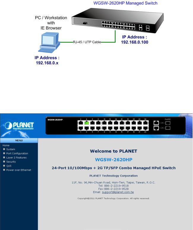
3.3 Web Management
The Managed Switch offers management features that allow users to manage the Managed Switch from anywhere on the network through a standard browser such as Microsoft Internet Explorer. After you set up your IP address for the switch, you can access the Managed Switch's Web interface applications directly in your Web browser by entering the IP address of the Managed Switch.
Figure 3-1: Web Management Diagram
You can then use your Web browser to list and manage the Managed Switch configuration parameters from one central location, just as if you were directly connected to the Managed Switch's console port. Web Management requires either
Microsoft Internet Explorer 6.0 or later, Safari or Mozilla Firefox 3.0 or later.
Figure 3-2: Web Main Screen of Managed Switch
26
User’s Manual of WGSW-2620HP
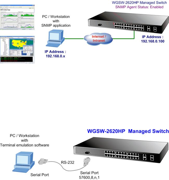
3.4 SNMP-Based Network Management
You can use an external SNMP-based application to configure and manage the Managed Switch, such as SNMPc Network Manager, HP Openview Network Node Management (NNM) or What’sup Gold. This management method requires the SNMP agent on the switch and the SNMP Network Management Station to use the same community string. This management method, in fact, uses two community strings: the get community string and the set community string. If the SNMP Net-work management Station only knows the set community string, it can read and write to the MIBs. However, if it only knows the get community string, it can only read MIBs. The default gets and sets community strings for the Managed Switch are public.
Figure 3-3: SNMP Management Diagram
3.5 Administration Console
The administration console is an internal, character-oriented, and command line user interface for performing system administration such as displaying statistics or changing option settings. Using this method, you can view the administration console from a terminal, personal computer, Apple Macintosh, or workstation connected to the switch's console (serial) port. There are two ways to use this management method: via direct access or modem port access. The following sections describe these methods. For more information about using the console, refer to Chapter 5 Console Management.
Figure 3-4: Console Management Diagram
27

User’s Manual of WGSW-2620HP
Direct Access
Direct access to the administration console is achieved by directly connecting a terminal or a PC equipped with a terminal-emulation program (such as HyperTerminal) to the Managed Switch console (serial) port.
When using this management method, a straight DB9 RS-232 cable is required to connect the switch to the PC. After making this connection, configure the terminal-emulation program to use the following parameters:
The default parameters are:
57600 bps
8 data bits
No parity
1 stop bit
Figure 3-5: Terminal Parameter Settings
You can change these settings, if desired, after you log on. This management method is often preferred because you can remain connected and monitor the system during system reboots. Also, certain error messages are sent to the serial port, regardless of the interface through which the associated action was initiated. A Macintosh or PC attachment can use any terminal-emulation program for connecting to the terminal serial port. A workstation attachment under UNIX can use an emulator such as TIP.
28

User’s Manual of WGSW-2620HP
3.6 Protocols
The Managed Switch supports the following protocols:
Virtual terminal protocols, such as Telnet
Simple Network Management Protocol (SNMP)
3.6.1 Virtual Terminal Protocols
A virtual terminal protocol is a software program, such as Telnet, that allows you to establish a management session from a Macintosh, a PC, or a UNIX workstation. Because Telnet runs over TCP/IP, you must have at least one IP address configured on the Managed Switch before you can establish access to it with a virtual terminal protocol.
Terminal emulation differs from a virtual terminal protocol in that you must connect a terminal directly to the console (serial) port.
To access the Managed Switch through a Telnet session:
1.Be Sure of the Managed Switch is configured with an IP address and the Managed Switch is reachable from a PC.
2.Start the Telnet program on a PC and connect to the Managed Switch.
The management interface is exactly the same with RS-232 console management.
3.6.2 SNMP Protocol
Simple Network Management Protocol (SNMP) is the standard management protocol for multi-vendor IP networks. SNMP supports transaction-based queries that allow the protocol to format messages and to transmit information between reporting devices and data-collection programs. SNMP runs on top of the User Datagram Protocol (UDP), offering a connectionless-mode service.
3.6.3 Management Architecture
All of the management application modules use the same Messaging Application Programming Interface (MAPI). By unifying management methods with a single MAPI, configuration parameters set using one method (console port, for example) are immediately displayable by the other management methods (for example, SNMP agent of Web browser). The management architecture of the switch adheres to the IEEE open standard. This compliance assures customers that the Managed Switch is compatible with, and will interoperate with other solutions that adhere to the same open standard.
29
User’s Manual of WGSW-2620HP
4. Web-Based Management
This section introduces the configuration and functions of the Web-Based management.
4.1 About Web-based Management
The Managed Switch offers management features that allow users to manage the Managed Switch from anywhere on the network through a standard browser such as Microsoft Internet Explorer.
The Web-Based Management supports Internet Explorer 6.0. It is based on Java Applets with an aim to reduce network bandwidth consumption, enhance access speed and present an easy viewing screen.
By default, IE6.0 or later version does not allow Java Applets to open sockets. The user has to explicitly modify the browser setting to enable Java Applets to use network ports.
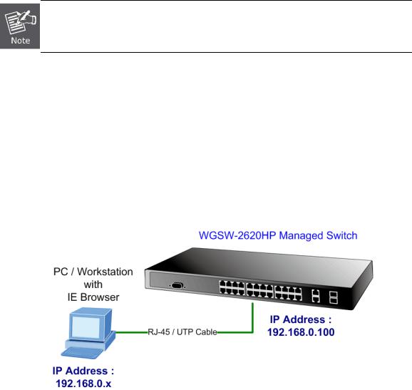
The Managed Switch can be configured through an Ethernet connection, make sure the manager PC must be set on same the IP subnet address with the Managed Switch.
For example, the default IP address of the Managed Switch is 192.168.0.100, then the manager PC should be set at
192.168.0.x (where x is a number between 1 and 254, except 100), and the default subnet mask is 255.255.255.0.
If you have changed the default IP address of the Managed Switch to 192.168.1.1 with subnet mask 255.255.255.0 via console, then the manager PC should be set at 192.168.1.x (where x is a number between 2 and 254) to do the relative configuration on manager PC.
30
Loading...