

Page 1
Configuration guide
Technical Catalogue 3.4 – August 2008 edition
PNOZmulti Modular Safety System
KURAL TEKNOLOJİ ELEKTRO MARKET
KURAL TECHNOLOGY ELECTRO MARKET
www.kuralteknoloji.com
bilgi@kuralteknoloji.com - info@kuralteknoloji.com
Page 2
Exclusion of liability
We have taken great care in
compiling our application manual. It
contains information about our
company and our products. All
statements are made in accordance
with the current status of technology
and to the best of our know-ledge
and belief. However, we cannot
except liability for the accuracy and
entirety of the information provided,
except in the case of gross
negligence. In particular it should be
noted that statements do not have
the legal quality of assurances or
assured properties. We are grateful
for any feedback on the contents.
August 2008
All rights to this publication are reserved by Pilz GmbH & Co. KG. We
reserve the right to amend
specifications without prior notice.
Copies may be made for the user’s
internal purposes. The names of
products, goods and technologies
used in this manual are trademarks
of the respective companies.
Why does Pilz offer more?
Because the integrality
of our business activities
is what sets us apart.
Pilz is a solution supplier for all automation functions. Including standard
control functions. Developments from
Pilz protect man, machine and the
environment. That’s why all our experience and knowledge goes into
individual products as well as
consistently sophisticated system
solutions.
Sensor technology
Control and communication
Motion Control
Operating and monitoring
Software
Consulting
Engineering
Training
Appropriate services relating to individual components and independent
generic services guarantee that our
customers obtain customised
automation solutions, all from one
source.
You can find more details about
Pilz and your products and
services on the Internet:
www.pilz.com
Pilz is a family business
that’s closer to its customers
Pilz has a tradition as a family-run
company stretching back over 50
years. Real proximity to customers is
visible in all areas, instilling
confidence through individual
consultation, flexibility and reliable
service.
We are your contact, guide and
competency leader en route to an
optimum automation solution.
Support –
Technical help round the clock!
Technical support is available from
Pilz round the clock. This service is
provided free of charge beyond
standard business hours.
You can reach our
international hotline on:
+49 711 3409-444
Page 3

Contents
3
Contents1.02007-11
Basics
1.0
System description
1.1
Installation
1.2
Electrical installation
1.3
Configuration and Wiring
1.4
Products
2.0
Selection guide
2.1
Base units
2.2
Expansion modules
2.3
Adapter for PNOZ ms1p and PNOZ ms2p
2.4
Software
2.5
Applications
3.0
Accessories
4.0
Order reference
5.0
Order reference
5.1
Standards and directives
6.0
Standards and directives
6.1
Service
7.0
Service
7.1
Page 4

Basics
Pilz GmbH & Co. KG, Sichere Automation, Felix-Wankel-Straße 2, 73760 Ostfildern, Germany
Telephone: +49 711 3409-0, Telefax: +49 711 3409-133, E-Mail: pilz.gmbh@pilz.de
1.0-0
1.0
Basics1.0
Page 5

Basics
Pilz GmbH & Co. KG, Sichere Automation, Felix-Wankel-Straße 2, 73760 Ostfildern, Germany
Telephone: +49 711 3409-0, Telefax: +49 711 3409-133, E-Mail: pilz.gmbh@pilz.de
2007-11
1.0-1
1.0
Contents Page
System description from 1.1-1
Installation from 1.2-1
Electrical installation from 1.3-1
Configuration and Wiring from 1.4-1
Page 6

Basics
System description
Pilz GmbH & Co. KG, Sichere Automation, Felix-Wankel-Straße 2, 73760 Ostfildern, Germany
Telephone: +49 711 3409-0, Telefax: +49 711 3409-133, E-Mail: pilz.gmbh@pilz.de
1.1-0
1.1
BasicsSystem description1.1
Page 7

Basics
Pilz GmbH & Co. KG, Sichere Automation, Felix-Wankel-Straße 2, 73760 Ostfildern, Germany
Telephone: +49 711 3409-0, Telefax: +49 711 3409-133, E-Mail: pilz.gmbh@pilz.de
System description
2007-11
1.1-1
1.1
Contents Page
System description
Overview 1.1-2
Hardware 1.1-3
Software 1.1-4
Maximum system expansion 1.1-5
Diagnostics 1.1-7
Safety 1.1-8
Page 8
Basics
System description
Overview
2007-11Pilz GmbH & Co. KG, Sichere Automation, Felix-Wankel-Straße 2, 73760 Ostfildern, Germany
Telephone: +49 711 3409-0, Telefax: +49 711 3409-133, E-Mail: pilz.gmbh@pilz.de
1.1-2
1.1
Overview1.12007-11BasicsSystem descriptionOverview
Modular design
` The modular safety system consists
of a base unit and several expansion modules.
` The base unit has several inputs
and outputs and is fully functional
even without an expansion module.
` The expansion modules supple-
ment the base unit with additional
inputs or outputs.
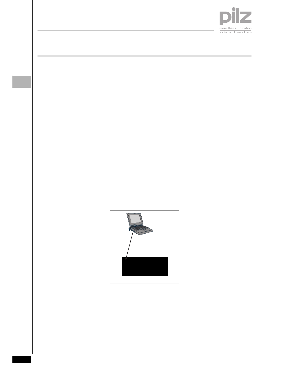
Configuration in the PNOZmulti
Configurator
` The function of the safety system is
established through the PNOZmulti
Configurator.
` The PNOZmulti Configurator is a
graphic tool which is used to define
the functions of the units. Using
predefined symbols, a simple circuit diagram shows how the units'
inputs and outputs should be connected. This circuit diagram is then
downloaded to the base unit.
` From this data, the base unit recog-
nises the safety functions it is to
perform. For example, safety functions such as E-STOP, two-hand
monitoring and safety gate monitoring are available. With the correct
circuitry it is possible to achieve
categories 2, 3 and 4 in accordance
with EN 954-1.
` The fact that the system is modular
and configurable guarantees the
highest level of flexibility. The safety
system can be expanded or the
safety functions modified at any
time.
Inputs
` Units in the PNOZmulti modular
safety system have semiconductor
inputs for safety-related and standard applications.
` The inputs for standard applica-
tions can also be set via the serial
interface or via fieldbus modules
(e.g. PROFIBUS-DP, CANopen, ...).
` One expansion module in the
PNOZmulti modular safety system
has safe, analogue inputs. The input signals are converted into digital signals.
` For standard applications, the ex-
act analogue values are made available to the base unit to forward to a
fieldbus.
Outputs
` Units in the PNOZmulti modular
safety system have both semiconductor and relay safety outputs.
` The outputs for standard functions
use semiconductor technology.
` The safety outputs use semicon-
ductor technology, require no maintenance and are non-wearing; they
are therefore suitable for applications with frequent operations or
cyclical functions. They can be
used for 24 VDC applications.
` The relay safety outputs are suita-
ble for less frequent operations, but
they have a higher breaking capacity and can be used for AC applications.
` The outputs for standard applica-
tions can also be evaluated via the
serial interface or via fieldbus modules (e.g. PROFIBUS-DP, CANopen, ...).
Base unit + expansion modules
Download
PNOZm Config
Page 9
Basics
Pilz GmbH & Co. KG, Sichere Automation, Felix-Wankel-Straße 2, 73760 Ostfildern, Germany
Telephone: +49 711 3409-0, Telefax: +49 711 3409-133, E-Mail: pilz.gmbh@pilz.de
System description
Hardware
2007-11
1.1-3
1.1
Hardware1.12007-11BasicsSystem descriptionHardwarePNOZmulti zusammengestell te Texte
Design of the modular safety system
The modular safety system consists of
the base unit and expansion modules.
The base unit itself has
` 20 inputs
` 2 relay outputs
` 4 semiconductor outputs
` 1 auxiliary output, which is required
for deleting the configuration data
in the base unit
` 1 cascading input
` 1 cascading output
The number of inputs and outputs can
be increased at any time using the expansion modules. The modules are
linked via a jumper. The system is configured using the PNOZmulti Configurator. Special expansion modules
enable data to be exchanged via a
fieldbus (non-safety-related) or safe
speed monitoring, for example.
Operation of the units
The PNOZmulti Configurator generates a project file which is downloaded
to the base unit; there it defines:
` Which safety functions the inputs
are to carry out, e.g. E-STOP monitoring, safety gate monitoring
` How the inputs are connected to
the outputs via logic functions
` Which output is configured (semi-
conductor, relay)
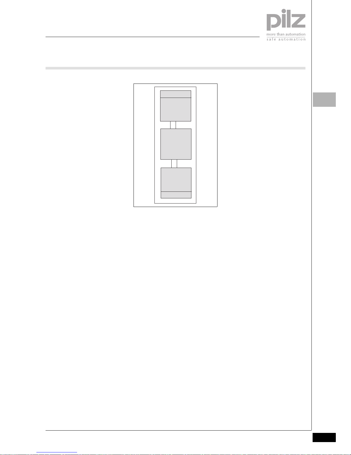
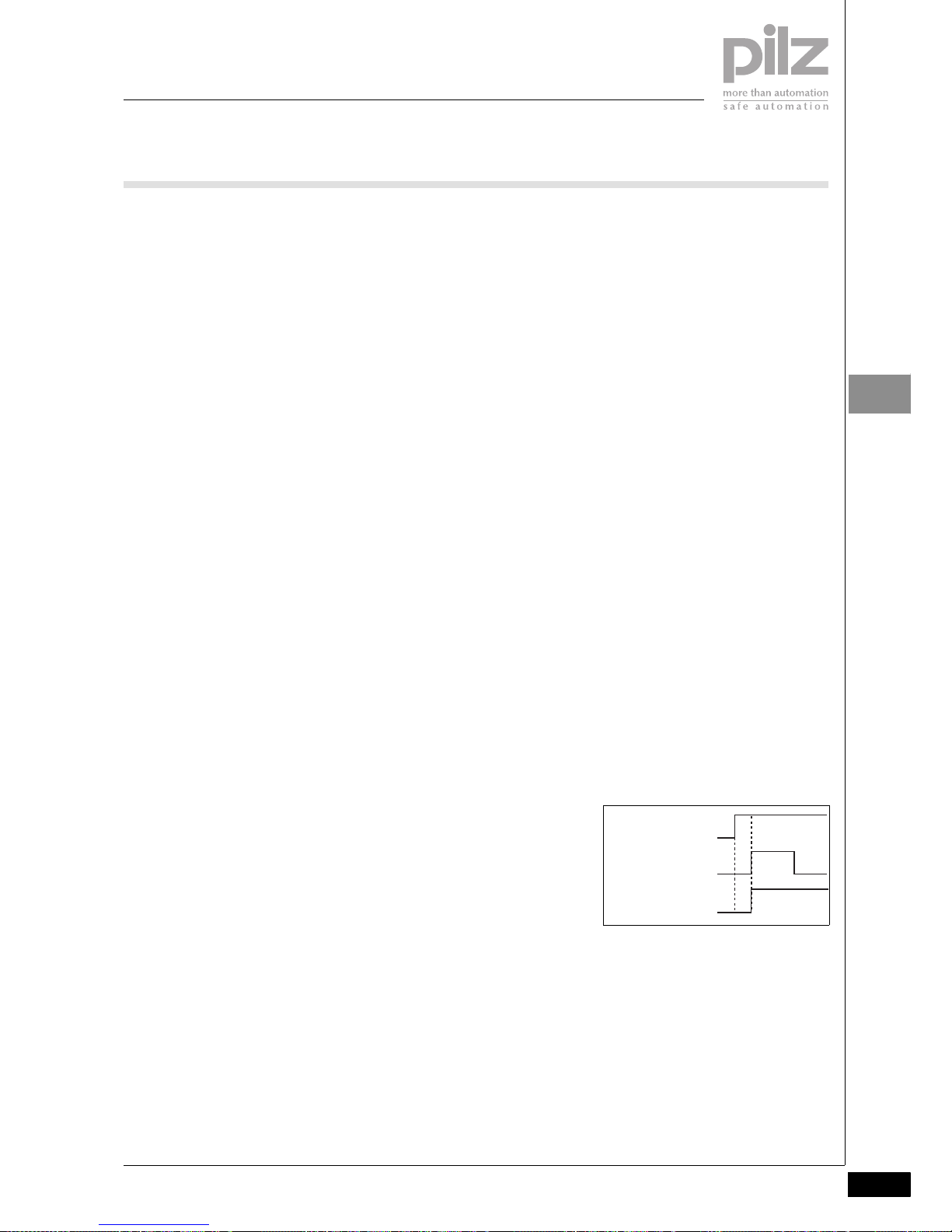
The units react the same, irrespective
of these functions:
If the start-up condition of the specific
safety function is met, there will be a
high signal at the output “Out1”. The
output signal can be linked via a logic
function and is then present as the
“Out2” signal at the output on the
PNOZmulti unit.
Fieldbus modules
The fieldbus modules are used to
` Read the diagnostic data
` Set virtual inputs for standard func-
tions
` Read virtual outputs for standard
functions
RS 232 interface
The base unit has an RS 232 interface
to
` Download the project
` Read the diagnostic data
` Set virtual inputs for standard func-
tions
` Read virtual outputs for standard
functions
Safety functions
The safety system has inputs and outputs, which can be used for safety
functions. The PNOZmulti safety system can be configured to monitor
` E-STOP pushbuttons
` Operating mode selector switches
` Enable switches
` Two-hand buttons
` Safety gates
` Light curtains
` Light beam devices
` Speeds
` Analogue input signals
` Safety mats
` Muting
`
Mechanical presses
` Standstill
Various switch types are available for
the required safety-related applications. With some switch types it is
possible to monitor for simultaneity
(see chapter on “Configuration and
Wiring”).
Standard functions
Expansion modules are available with
inputs and outputs for standard functions.
Press applications
The PNOZ m2p base unit is designed
for applications on mechanical presses.
Inputs
Safety
functions
e.g.
E-STOP
safety gate
Outputs
Out1
Logic
functions
e.g.
AND
OR
Delay
Out2
Semiconductor
Relay
Page 10

Basics
System description
Software
2006-02Pilz GmbH & Co. KG, Sichere Automation, Felix-Wankel-Straße 2, 73760 Ostfildern, Germany
Telephone: +49 711 3409-0, Telefax: +49 711 3409-133, E-Mail: pilz.gmbh@pilz.de
1.1-4
1.1
Software1.12006-02BasicsSystem descriptionSoftware
The functions of the PNOZmulti system are defined in the PNOZmulti
Configurator software.
Procedure
` In the PNOZmulti Configurator, the
first step is to enter the units that
are to be used in the safety system.
Each unit must be given a resource
label.
` When all the units are selected, the
interface appears for entering the
circuit diagram. The circuit diagram
describes the application for which
the safety system is to be used. It is
here that you determine which in-
puts are assigned to which safety-
related or standard functions.
` The inputs and/or the results of the
safety-related or standard functions
can be linked through logic func-
tions. The results of the logic func-
tions or the results of the safety-
related or standard functions are
channelled to the outputs on the
PNOZmulti units.
` The circuit diagram is generated on
a graphical interface. Symbols are
provided for the safety-related or
standard functions, logic functions
and the various output types. These
are simply dragged on to a work-
space, configured and intercon-
nected.
` Once the circuit diagram is com-
plete, the data must be saved and
downloaded to the base unit. The
circuit diagram, unit configuration
and all the data that has been en-
tered are stored within a project.
` When the project is saved, various
passwords can be used to protect it
from unauthorised access.
` Once it is saved, the project has to
be downloaded to the base unit. To
do this, the project data is down-
loaded on to a chip card. The data
is either downloaded via the RS 232
interface or via a chip card reader.
` After downloading, a test must be
performed to check that the safety
devices function correctly.
Page 11
Basics
Pilz GmbH & Co. KG, Sichere Automation, Felix-Wankel-Straße 2, 73760 Ostfildern, Germany
Telephone: +49 711 3409-0, Telefax: +49 711 3409-133, E-Mail: pilz.gmbh@pilz.de
System description
Maximum system expansion
2007-11
1.1-5
1.1
Maximum system expansion1.12007-11BasicsSystem descriptionMaximum system expansion
The PNOZmulti Configurator software
provides support when assembling a
PNOZmulti system. The maximum
system expansion is limited only by
the maximum permitted number of expansion modules that can be connected.
The following modules are available:
` Base units
` Expansion modules
` Fieldbus modules
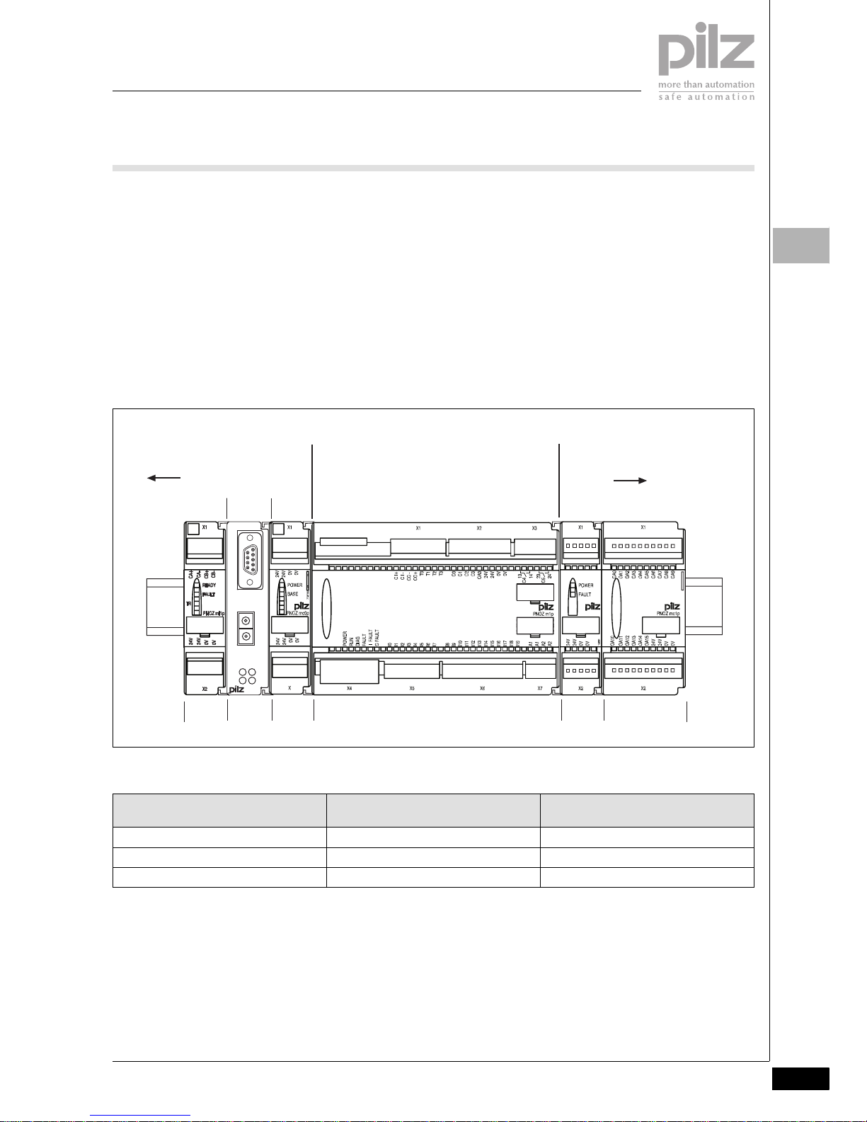
Positioning of units
` Only one base unit may be used.
` Expansion modules and a fieldbus
module may be connected to the
left or right, depending on the base
unit type. The maximum number
per type is given in the tables below.
` The position of the expansion mod-
ules is defined in the PNOZmulti
Configurator.
` Expansion modules for safety-relat-
ed and standard applications may
be combined as required.
` However, if expansion modules of
the same function are combined
into groups it makes things clearer
and simplifies the wiring.
` The power supply for a fieldbus
module is not given a position
number.
` If there is no fieldbus module, the
position numbers to the left of the
base unit will be -1 ... -4.
Base units:
CHIP-Card
PNOZ mo3p
O1+
O0-
O0+
O1-
PROFIBUS-DP
PNOZ mc3p
FAULT
OFFLINE
x1
x10
X1
ONLINE
ADDRESS
773700
Base unit
Fieldbus module
Max. 8 expansion
modules
8
Position
1
2
...
2
Shield
Power supply
Max. 4 expansion
modules
0-5 -1-2...
Unit type Max. number of expansion modules
installed on the left
Max. number of expansion modules
installed on the right
PNOZ m0p 4 + 1 fieldbus module --PNOZ m1p 4 + 1 fieldbus module 8
PNOZ m2p 4 + 1 fieldbus module 8
Page 12

Basics
System description
Maximum system expansion
2007-11Pilz GmbH & Co. KG, Sichere Automation, Felix-Wankel-Straße 2, 73760 Ostfildern, Germany
Telephone: +49 711 3409-0, Telefax: +49 711 3409-133, E-Mail: pilz.gmbh@pilz.de
1.1-6
1.1
Expansion modules:
Fieldbus modules:
Unit type Function Max. number of expansion
modules
installed on the left
Max. number of expansion
modules
installed on the right
PNOZ ma1p 2 safe analogue inputs 4 --PNOZ mc1p 16 outputs for standard func-
tions
--- 8
PNOZ mi1p 8 safe inputs --- 8
PNOZ mi2p 8 inputs for standard functions --- 8
PNOZ ml1p Connection module for 32 virtu-
al inputs and outputs
4 ---
PNOZ mo1p 4 safe 1-pole semiconductor
outputs
--- 6
PNOZ mo2p 2 safe relay outputs --- 6
PNOZ mo3p 2 safe 2-pole semiconductor
outputs
--- 6
PNOZ mo4p 4 safe relay outputs --- 6
PNOZ ms1p 2 incremental encoders or
proximity switches
--- 4
PNOZ ms1p 2 incremental encoders or
proximity switches
--- 4
Unit type Fieldbus Max. number of expansion
modules
installed on the left
Max. number of expansion
modules
installed on the right
PNOZ mc3p PROFIBUS-DP 1 --PNOZ mc4p DeviceNet 1 --PNOZ mc5p Interbus 1 --PNOZ mc5.1p Interbus fibre-optic cable 1 --PNOZ mc6p CANopen 1 --PNOZ mc7p CC-Link 1 --PNOZ mc8p Ethernet IP/Modbus TCP 1 --PNOZ mc9p PROFINET IO 1 ---
Page 13

Basics
Pilz GmbH & Co. KG, Sichere Automation, Felix-Wankel-Straße 2, 73760 Ostfildern, Germany
Telephone: +49 711 3409-0, Telefax: +49 711 3409-133, E-Mail: pilz.gmbh@pilz.de
System description
Diagnostics
2006-02
1.1-7
1.1
Diagnostics1.12006-02BasicsSystem descriptionDiagnostics
The PNOZmulti has many options for
diagnostics and fault detection:
` LEDs on the base unit and expan-
sion modules
` Diagnostic data via serial interface
and fieldbus
` Expanded diagnostic options using
a visualisation system, e.g. PMImi-
cro diag
` Error stack
` Diagnostic word in the PNOZmulti
Configurator
Note
Please refer to the chapters
` “Diagnostic interface” and
` “Diagnostic word”
in the configuration guide “PNOZmulti
– Special applications”.
LEDs on the base unit and expansion modules
The LEDs signal
` Operating statuses (e.g. “RUN”)
` External and internal errors
The key to the LEDs can be found in
the operating instructions supplied
with the units.
Diagnostic Interface
The serial interface on the PNOZmulti
modular safety system is used to
transfer diagnostic data to a user program.
Diagnostic data
The diagnostic data can be called up
via the serial interface or via a connected fieldbus.
The diagnostic data may only be used
for non-safety purposes, e.g. visualisation.
Diagnostic data on the PNOZmulti
modular safety system comprises:
` Version:
Product number, unit version, serial
number
` Status of inputs/outputs:
Indicates whether inputs and out-
puts are active or inactive (open/
closed)
` LED status:
Indicates the status of the LEDs on
the base unit and expansion mod-
ules (on/off/flashes), plus the operating mode (start up, RUN, STOP)
` Simplified status scan:
Shows group messages relating to
the safety system: Signal changes,
LED status, operating statuses
` Virtual inputs and outputs:
Virtual inputs can be set. The status
of the virtual inputs and outputs can
be scanned.
` Diagnostic word:
The diagnostic word contains the
status of elements from the user
program within the PNOZmulti.
` Test data:
To check commmunication.
` Data in table form:
This is structured data (arranged in
tables and segments) from the
PNOZmulti, as it could also be read
via a fieldbus module:
– Configuration
– Status of the inputs and outputs
–LED status
– Diagnostic word
–Element types
Expanded diagnostic options using
a diagnostic terminal, e.g. PMImicro
diag
An expanded diagnsotic configuration
can be created in the PNOZmulti Configurator. The diagnostic configuration
enables appropriate event messages
to be displayed in the case of:
` Errors in or on the PNOZmulti:
Contains the event messages that
are triggered when there are errors
in or on the PNOZmulti (error stack)
` Changes in the operating status of
the PNOZmulti
` which are triggered when safety de-
vices, inputs, outputs and connec-
tion points have a defined status
PNOZmulti event messages can also
be supplemented through additional
information, which is helpful during diagnostics.
With expanded diagnostics, a display
unit (e.g. PMImicro diag) is connected
to a PNOZmulti. If an event occurs in
or on the PNOZmulti, an event telegram is sent to the display unit. The
event telegram is evaluated in the display unit. In most cases, the event
message that corresponds to the
event is displayed and is entered in the
event list. The event message contains
a description of the event. A remedy
can be displayed for each event message. The remedy describes how to
react to the event, in other words,
what “actions” to take.
The diagnostic configuration is
project-related, i.e. a separate diagnostic configuration is created for
each PNOZmulti project (see Create a
diagnostic configuration).
Then the diagnostic configuration is
downloaded to the PNOZmulti and to
the display unit.
The diagnostic configuration is described in detail in the PNOZmulti
Configurator's online help.
Error stack
The error stack on the PNOZmulti contains important information for diagnostics and troubleshooting. The error
stack can be read out by the PNOZmulti Configurator. It contains messages and help texts such as
` Hardware errors
` Wiring errors
` Configuration errors
` Errors in the operation of the inter-
face or fieldbus
` Errors in the project's user program
` Messages relating to differences
between the programs stored on
the PNOZmulti and chip card
Diagnostic word
A diagnostic word can be called up for
those elements of the PNOZmulti Configurator interface that have the ability
to store a status:
` Online in the PNOZmulti Configura-
tor
` Via the base unit's serial interface
` Via a connected fieldbus
The diagnostic word contains information about a certain element, e.g.:
` Operating statuses (e.g. switch op-
erated)
` Error messages (e.g. monitoring
time elapsed)
An individual bit from a diagnostic
word can be evaluated in the user program of the PNOZmulti Configurator.
Page 14

Basics
System description
Safety
2006-02Pilz GmbH & Co. KG, Sichere Automation, Felix-Wankel-Straße 2, 73760 Ostfildern, Germany
Telephone: +49 711 3409-0, Telefax: +49 711 3409-133, E-Mail: pilz.gmbh@pilz.de
1.1-8
1.1
Safety1.12006-02BasicsSystem descriptionSafetyPNOZmulti z usammengestellte Te xte
Safety assessments
Before using a unit it is necessary to
perform a safety assessment in accordance with the Machinery Directive. The safety system guarantees
functional safety, but not the safety of
the entire application. You should
therefore define the safety requirements for the plant as a whole, and
also define how these will be implemented from a technical and organisational standpoint.
General safety requirements
Always ensure the following safety requirements are met:
` Only install and commission the
unit if you are familiar with the information in the operating instructions
or this technical catalogue, as well
as the relevant regulations concerning health and safety at work and
accident prevention.
` Only use the unit for the purpose for
which it is intended and comply
with both the general and specific
technical details.
` Transport, storage and operating
conditions should all conform to EN
60068-2-6, 01/00 (see general
technical details).
` Adequate protection must be pro-
vided for all inductive consumers.
` Do not open the housing or make
any unauthorised modifications.
` Failure to comply with the safety re-
quirements will render the guarantee invalid.
Intended use
` The PNOZmulti Configurator soft-
ware is designed to configure units
from the PNOZmulti modular safety
system for use on E-STOP equipment and safety circuits, in accordance with EN 60204-1 (VDE 0113-
1), 11/98 and IEC 60204-1, 12/97.
` The units' intended use depends on
the individual unit and is therefore
explained in the chapter entitled
“Units”.
` The PNOZ m2p base unit is de-
signed for applications on mechanical presses. Please refer to the
safety guidelines in the chapter on
“Safety solutions for presses” in the
configuration guide “PNOZmulti –
Special applications”.
Page 15

Basics
Pilz GmbH & Co. KG, Sichere Automation, Felix-Wankel-Straße 2, 73760 Ostfildern, Germany
Telephone: +49 711 3409-0, Telefax: +49 711 3409-133, E-Mail: pilz.gmbh@pilz.de
System description
Safety
2006-02
1.1-9
1.1
Page 16

Basics
Installation
Pilz GmbH & Co. KG, Sichere Automation, Felix-Wankel-Straße 2, 73760 Ostfildern, Germany
Telephone: +49 711 3409-0, Telefax: +49 711 3409-133, E-Mail: pilz.gmbh@pilz.de
1.2-0
1.2
BasicsInstallation1.2
Page 17

Basics
Pilz GmbH & Co. KG, Sichere Automation, Felix-Wankel-Straße 2, 73760 Ostfildern, Germany
Telephone: +49 711 3409-0, Telefax: +49 711 3409-133, E-Mail: pilz.gmbh@pilz.de
Installation
2007-11
1.2-1
1.2
Contents Page
Installation
Installing within the control cabinet 1.2-2
Installing the units 1.2-3
Page 18

Basics
Installation
Installing within the control cabinet
2006-02Pilz GmbH & Co. KG, Sichere Automation, Felix-Wankel-Straße 2, 73760 Ostfildern, Germany
Telephone: +49 711 3409-0, Telefax: +49 711 3409-133, E-Mail: pilz.gmbh@pilz.de
1.2-2
1.2
Installing within the control cabinet1.22006-02BasicsInstallationInstalling within the control cabinetPNOZmulti zusammengestell te Texte
` The safety system should be in-
stalled in a control cabinet with a
protection type of at least IP54. Fit
the safety system to a horizontal
DIN rail. The venting slots must face
upward and downward. Other
mounting positions could destroy
the safety system.
` Use the notches on the back of the
unit to attach it to a DIN rail. Connect the safety system to the DIN
rail in an upright position, so that
the earthing springs on the safety
system are pressed on to the DIN
rail.
` The ambient temperature of the
PNOZmulti units in the control cabinet must not exceed the figure
stated in the technical details, otherwise air conditioning will be required.
` To comply with EMC requirements,
the DIN rail must have a low impedance connection to the control cabinet housing.
Positioning of units
` Expansion modules and a fieldbus
module may be connected, depending on the base unit type.
` Install the expansion modules in the
position defined in the PNOZmulti
Configurator (see section entitled
“Maximum system expansion” in
Chapter 1.1 “System Description”).
Page 19
Basics
Pilz GmbH & Co. KG, Sichere Automation, Felix-Wankel-Straße 2, 73760 Ostfildern, Germany
Telephone: +49 711 3409-0, Telefax: +49 711 3409-133, E-Mail: pilz.gmbh@pilz.de
Installation
Installing the units
2006-02
1.2-3
1.2
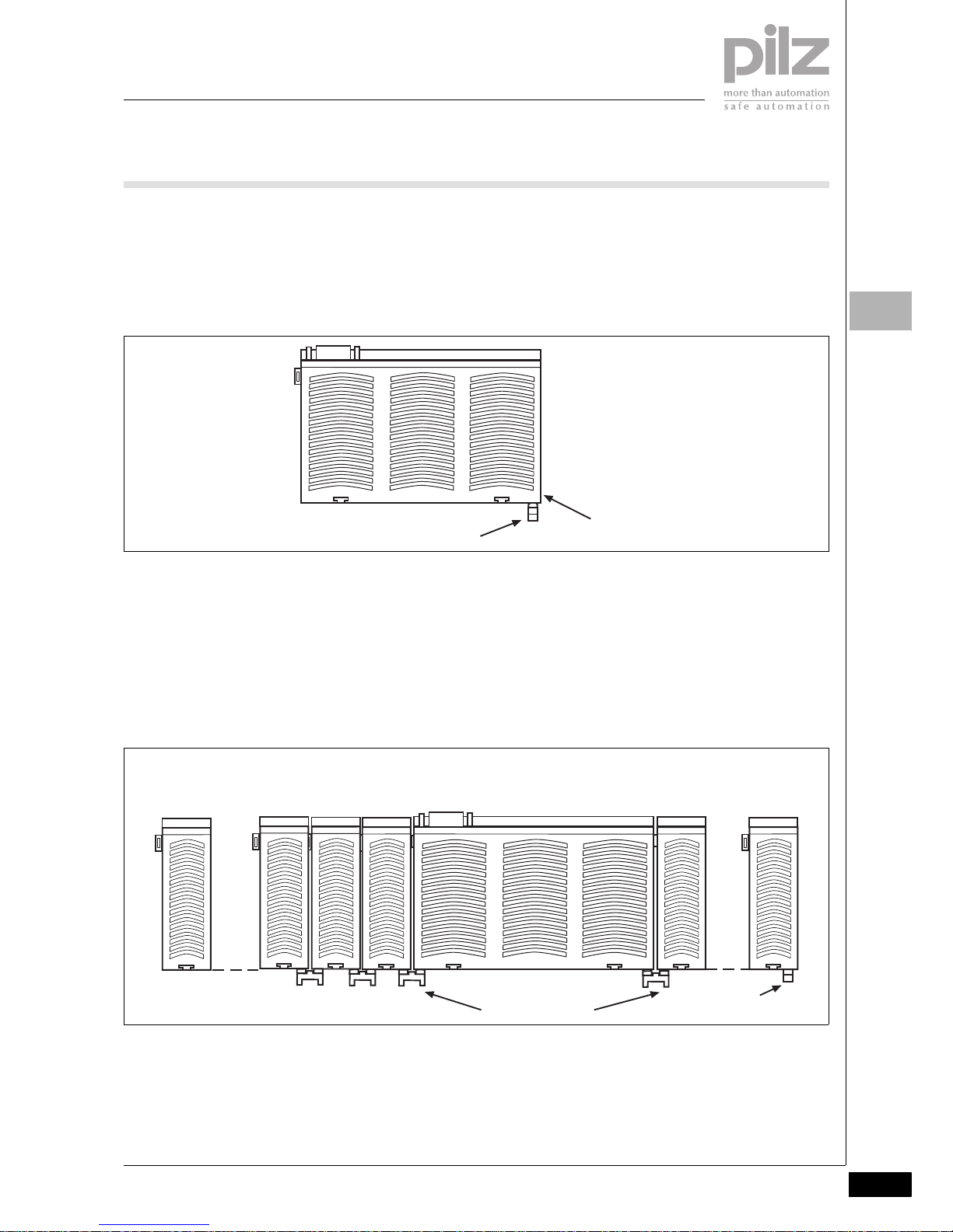
Installing the units1.22006-02BasicsInstallationInstalling the units
Installing a base unit without expansion modules
` The terminator must be fitted to the
side of the base unit marked “Termination/Link”.
` Do not fit a terminator to the left
side of the base unit.
Connecting the base unit and expansion modules (PNOZ m1p, PNOZ
m1p coated version, PNOZ m2p only)
Jumpers are used to connect the
modules.
There are 2 pin connectors on the rear
of the base unit.
` Make sure that no terminator is fit-
ted.
` Connect the base unit, the expan-
sion modules and the fieldbus module using the jumpers supplied.
` The terminator must be fitted to the
last expansion module to the right
of the base unit.
` Do not fit a terminator to the last ex-
pansion module to the left of the
base unit.
Terminator
Termination/Link
Expansion module 1 ... 8
Jumpers
Terminator
Fieldbus module
Base unit
Expansion module 1 ... 4
Power supply
Page 20

Basics
Electrical installation
Pilz GmbH & Co. KG, Sichere Automation, Felix-Wankel-Straße 2, 73760 Ostfildern, Germany
Telephone: +49 711 3409-0, Telefax: +49 711 3409-133, E-Mail: pilz.gmbh@pilz.de
1.3-0
1.3
BasicsElectrical installation1.3
Page 21

Basics
Pilz GmbH & Co. KG, Sichere Automation, Felix-Wankel-Straße 2, 73760 Ostfildern, Germany
Telephone: +49 711 3409-0, Telefax: +49 711 3409-133, E-Mail: pilz.gmbh@pilz.de
Electrical installation
2007-11
1.3-1
1.3
Contents Page
Electrical installation
General requirements 1.3-2
Page 22

Basics
Electrical installation
General requirements
2006-02Pilz GmbH & Co. KG, Sichere Automation, Felix-Wankel-Straße 2, 73760 Ostfildern, Germany
Telephone: +49 711 3409-0, Telefax: +49 711 3409-133, E-Mail: pilz.gmbh@pilz.de
1.3-2
1.3
General requirements1.32006-02BasicsElectrical installationGeneral requirementsPNOZmulti zusammengestellte T exte
EMC
` The PNOZmulti is designed for use
in an industrial environment. It is not
suitable for use in a domestic environment, as this can lead to interference.
` To comply with EMC requirements,
the DIN rail must have a low impedance connection to the control cabinet housing.
Supply voltage
` Power for the safety system and in-
put circuits must always be provided from a single power supply. The
power supply must meet the regulations for extra low voltages with
safe separation (SELV, PELV).
` Two connection terminals are avail-
able for each of the supply connections 24 V and 0 V (semiconductor
outputs), plus A1 and A2 (power
supply). This means that the supply
voltage can be looped through several connections. The current at
each terminal may not exceed 9 A.
Cables
` Do not route the test pulse lines to-
gether with actuator cables within
an unprotected multicore cable.
` Use copper wiring that can with-
stand temperatures of 60/75°C.
Terminals
` The plug-in terminals for the inputs
and outputs are not supplied with
the system. You can select between a cage clamp connection or
a screw connection.
` The plug-in connection terminals
on the relay outputs carry mains
voltage and should only be connected and disconnected when the
voltage is switched off.
ESD
Electrostatic discharge can damage
components. Ensure against discharge before touching the units, e.g.
by touching an earthed, conductive
surface or by wearing an earthed armband.
Page 23

Basics
Pilz GmbH & Co. KG, Sichere Automation, Felix-Wankel-Straße 2, 73760 Ostfildern, Germany
Telephone: +49 711 3409-0, Telefax: +49 711 3409-133, E-Mail: pilz.gmbh@pilz.de
Electrical installation
General requirements
2006-02
1.3-3
1.3
Page 24

Basics
Configuration and Wiring
Pilz GmbH & Co. KG, Sichere Automation, Felix-Wankel-Straße 2, 73760 Ostfildern, Germany
Telephone: +49 711 3409-0, Telefax: +49 711 3409-133, E-Mail: pilz.gmbh@pilz.de
1.4-0
1.4
BasicsConfiguration and Wiring1.4
Page 25

Basics
Pilz GmbH & Co. KG, Sichere Automation, Felix-Wankel-Straße 2, 73760 Ostfildern, Germany
Telephone: +49 711 3409-0, Telefax: +49 711 3409-133, E-Mail: pilz.gmbh@pilz.de
Configuration and Wiring
2007-11
1.4-1
1.4
Contents Page
Configuration and Wiring
Inputs 1.4-2
Logic elements 1.4-7
Outputs 1.4-8
Inputs and outputs for standard functions 1.4-9
Cascading 1.4-10
Page 26

Basics
Configuration and Wiring
Inputs
2007-11Pilz GmbH & Co. KG, Sichere Automation, Felix-Wankel-Straße 2, 73760 Ostfildern, Germany
Telephone: +49 711 3409-0, Telefax: +49 711 3409-133, E-Mail: pilz.gmbh@pilz.de
1.4-2
1.4
Inputs1.42007-11BasicsConfiguration and WiringInputsPNOZmulti zusammengestell te Texte
Connection options
Depending on the unit type, the following may be connected to the inputs on
the PNOZmulti:
` E-STOP pushbutton
` Safety gate limit switch
` Two-hand button
` Reset button
` Light beam device, light curtain
` Safety mats
` Enable switch
` Operating mode selector switch
` Proximity switch
` Incremental encoder
` Foot switch
` Key switch
` Limit switch
` Pushbutton
` Encoder or transducer to monitor
safe analogue input signals
The PNOZmulti has inputs for both
safety-related and standard applications.
` Only safety inputs should be used
for safety-related applications.
` Inputs for standard functions may
be used for a reset button, for example.
Application with safety mats
The application with safety mats is described in detail in the configuration
guide under “Special applications”.
Configuration in the PNOZmulti
Configurator
The inputs on the PNOZmulti units are
configured in the PNOZmulti Configurator.
For example, you can define the following:
` Switch types for various safety
functions
` Connection assignment
` Detection of shorts between con-
tacts in the input circuit
` Reset types
` Start-up test
` Detection of shorts between con-
tacts in the reset circuit with test
pulse assignment
` Input for standard function
Some configuration options can only
be selected for particular safety functions (e.g. the start-up test can only be
selected for the safety gate and light
curtain safety functions).
Input signals
Due to the cyclical processing, changes in the input signal will only be detected safely if the off-time >15 ms.
Connection assignment
Inputs on the PNOZmulti units are assigned to particular safety functions
(e.g. E-STOP, safety gate) in the
PNOZmulti Configurator. The safety
contacts must be connected to the inputs on the PNOZmulti units in accordance with their configuration.
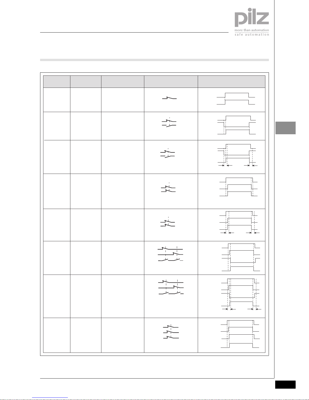
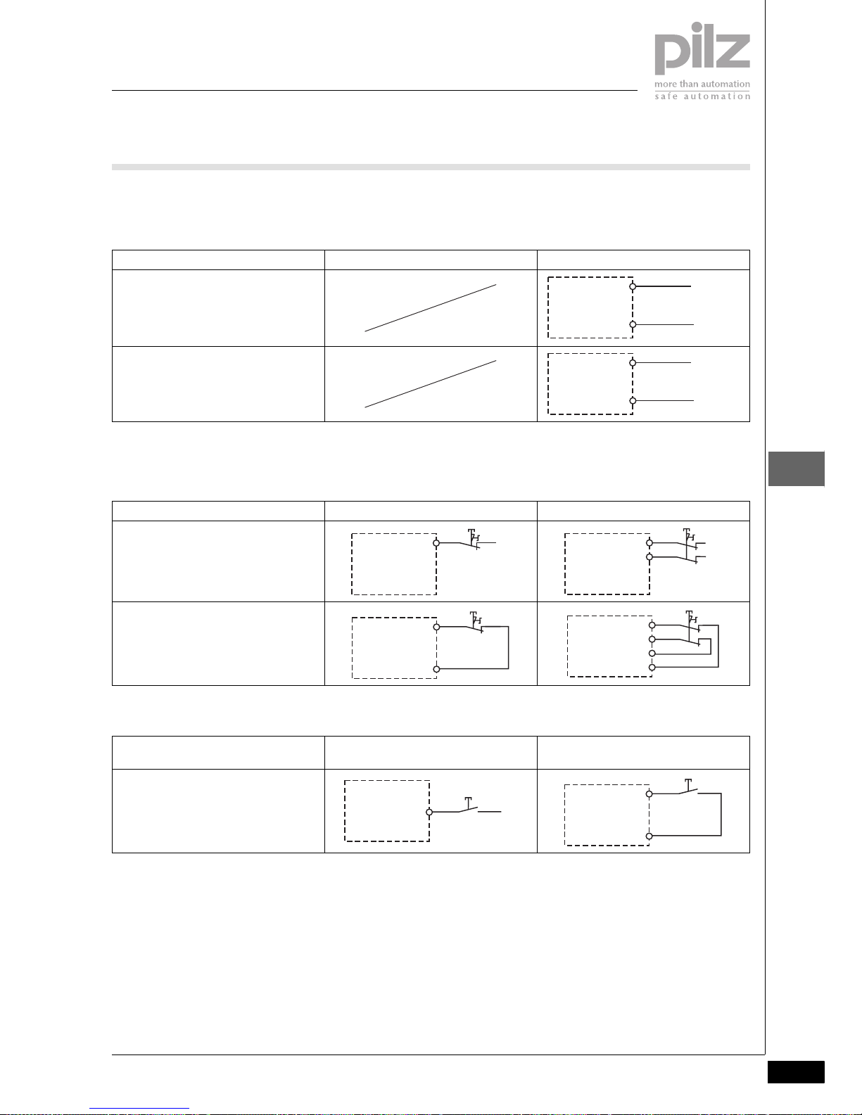
Select switch type
The PNOZmulti Configurator provides
the user with various switch types for
safety-related applications. The switch
types that can be selected will depend
on the type of input element (e.g. ESTOP, safety gate). The switches
drawn below are shown in the state
when not activated, such as with the
safety gate closed or E-STOP not
pressed.
On switches that are monitored for simultaneity, the maximum switch-on
time and the maximum switch-off time
are the same. These values can be
found in the “Description” and “Timing
diagram” columns.
Page 27
Basics
Pilz GmbH & Co. KG, Sichere Automation, Felix-Wankel-Straße 2, 73760 Ostfildern, Germany
Telephone: +49 711 3409-0, Telefax: +49 711 3409-133, E-Mail: pilz.gmbh@pilz.de
Configuration and Wiring
Inputs
2007-11
1.4-3
1.4
Application Description Switch symbol Timing diagram
E-STOP
Safety gate
Enable switch
Foot switch
Safety contacts:
1 normally closed (N/C)
without on and off-time
1
E-STOP
Safety gate
Foot switch
Safety contacts:
1 normally closed (N/C)
1 normally open (N/O)
without on and off-time
E-STOP
Safety gate
Foot switch
Safety contacts:
1 normally closed
(N/C)
1 normally open
(N/O)
with on and off-time
3 s
2
Safety contacts:
2
normally closed
(N/C)
without on and offtime
2 Simultaneity
E-STOP
Safety gate
Safety gate
with
Interlock
Light curtain
Enable switch
Foot switch
3
3 Simultaneity
E-STOP
Safety gate
Light curtain
Enable switch
Foot switch
Safety contacts:
2 normally closed
(N/C)
with on and off-time
3 s
4 Safety contacts:
2 normally closed (N/C)
1 normally open (N/O)
without on and off-time
Safety
gate
4 Simultaneity
Safety contacts:
2 normally closed (N/C)
1 Schließer (S)
with on and off-time 3 s
Safety
gate
5 Safety contacts:
3 normally closed (N/C)
without on and off-time
Safety
gate
Switch type
t
t
t
t
N/C
Output
N/O
Output
N/C
max. 3 s
max. 3 s
N/O
Output
N/C
N/C
Output
N/C
N/C
Output
N/C
max. 3 s
max. 3 s
N/C
Output
N/C
N/O
N/C
Output
N/C
max. 3 s
max. 3 s
N/O
N/C
Output
N/C
N/C
Page 28
Basics
Configuration and Wiring
Inputs
2007-11Pilz GmbH & Co. KG, Sichere Automation, Felix-Wankel-Straße 2, 73760 Ostfildern, Germany
Telephone: +49 711 3409-0, Telefax: +49 711 3409-133, E-Mail: pilz.gmbh@pilz.de
1.4-4
1.4
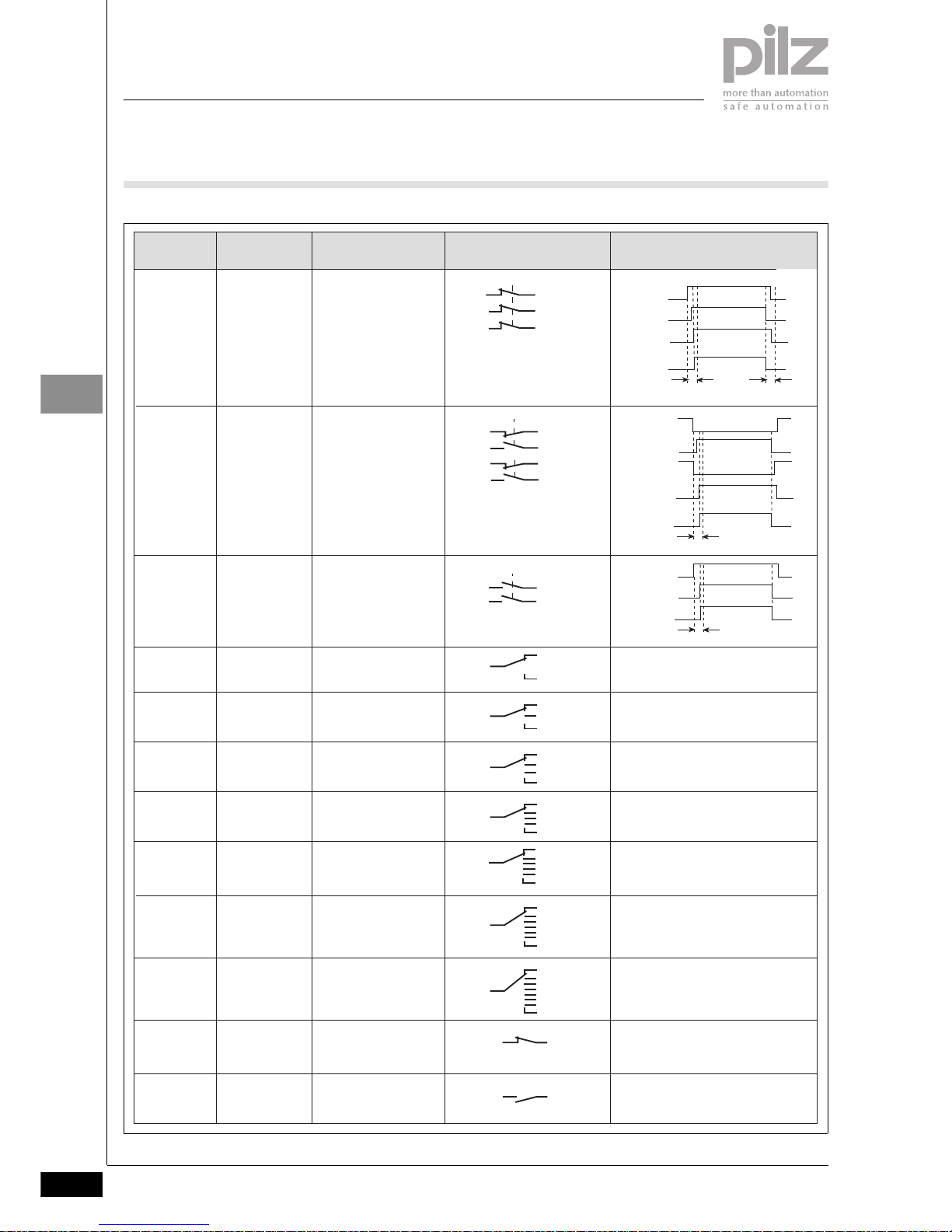
5 Simultaneity
Safety contacts:
3 normally closed (N/C)
with on and off-time 3 s
Safety
gate
Safety contacts:
2 changeover contacts
(C/O) with simultaneity
monitoring 0.5 s, off-time
not monitored
Safety contacts:
2 normally open (N/O)
(C/O) with simultaneity
monitoring 0.5 s, off-time
not monitored
Two-hand button
Ohne Taktung
nur bis Kategorie
1 nach EN 954-1
einsetzbar
7
9
Operating mode Safety contacts:
Switch 1 from 2
10 Operating mode Safety contacts:
Switch 1 from 3
11 Operating mode Safety contacts:
Switch 1 from 4
12 Operating mode Safety contacts:
Switch 1 from 5
13 Operating mode Safety contacts:
Switch 1 from 6
14 Operating mode Safety contacts:
Switch 1 from 7
15 Operating mode Safety contacts:
Switch 1 from 8
Button
Key switch
Limit switch
Safety contacts:
1 normally closed (N/C)
16
Safety contacts:
1 normally open (N/O)
17
Two-hand
button
6
N/C
Output
N/C
max. 3 s
max. 3 s
N/C
N/C 1
Output
N/O 1
max. 0,5 s
N/C 2
N/O 2
Output
N/O 1
max. 0,5 s
N/O 2
t
t
Application Description Switch symbol Timing diagramSwitch type
Button
Key switch
Limit switch
Page 29
Basics
Pilz GmbH & Co. KG, Sichere Automation, Felix-Wankel-Straße 2, 73760 Ostfildern, Germany
Telephone: +49 711 3409-0, Telefax: +49 711 3409-133, E-Mail: pilz.gmbh@pilz.de
Configuration and Wiring
Inputs
2007-11
1.4-5
1.4
Input devices
When selecting input devices, you
must comply with the technical details
of the input circuits on the PNOZmulti
units. To help you in your selection,
Pilz has performed application tests
with a number of input devices. The
following input devices have passed
the application test:
` Light curtains:
–SICK FGS
– SICK C4000
– Honeywell MEYLAN
– CEDES Safe 4
–OMRON F3SN-A
– Fiessler ULVT
– STI Minisafe MS 4600 (from S/N:
AC283791 / BA022933)
– STI Optofence OF 4600
` Limit switches:
– Schmersal AZ 16-02
– Guardmaster ferrocode
– Euchner NP1-628AS
– Euchner CES-A-C5E-01 (only
when operating without detection of shorts across contacts)
– Euchner CES-A-C5E-01 (only
with test pulse wiring)
– Euchner ENG-071990
– Euchner NM11KB
The following may not be used:
` Limit switches:
– Euchner CES-A-C5E-01 with
pulse signals
The following is generally valid: Input
devices with mechanical contacts (relays) can be used in operating modes
with or without detection of shorts
across contacts, provided you comply
with the technical details. It is not always possible to use input devices
with semiconductor outputs when operating with detection of shorts across
contacts.
Units with OSSD semiconductor
outputs
Units with OSSD semiconductor outputs (e.g. self-testing light barriers)
may only be used if the PNOZmulti is
operated without detection of shorts
across contacts.
ESPE
If the function of an ESPE (e.g. light
barrier) is switched off via an operating
mode selector switch, the supply voltage to the ESPE must be switched off
at the same time.
Operating modes
The following operating modes are
available, depending on the selected
safety function:
` Single-channel operation: Input
wiring in accordance with EN
60204, no redundancy in the input
circuit; earth faults in the input circuit are detected.
` Dual-channel operation: Redun-
dant input circuit; earth faults in the
input circuit are detected, with or
without detection of shorts between the input contacts.
` Triple-channel operation: Redun-
dant input circuit; earth faults in the
input circuit are detected, with or
without detection of shorts between the input contacts.
` Automatic reset: Unit is active as
soon as the input circuit is closed.
` Manual reset: The unit is not active
until the reset button has been operated.
` Monitored reset: Unit is not active
until the reset button has been operated and then released. This eliminates the possibility of the reset
button being overridden, triggering
automatic activation.
` Detection of shorts between con-
tacts in the input circuit: Enabled by
pulsing the input circuits. This operating mode is automatically detected on start-up.
` Detection of shorts between con-
tacts in the reset circuit:
` Only on E-STOP, safety gate and
light curtain
` Start-up test: The unit checks
whether safety gates that are
closed are opened and then closed
again when supply voltage is applied.
` Increase in the number of safety
contacts available by connecting a
contact block (e.g. PZE 9P) or external contactors.
Reset button
A reset button triggers an enable for a
safety device when all the corresponding safety switches (e.g. E-STOP) are
closed. This prevents a machine starting up automatically after the supply
has been interrupted or after a safety
device has closed, for example.
Reset modes
When configuring inputs for E-STOPs,
safety gates or light guards in the
PNOZmulti Configurator, it is possible
to define the reset mode:
` Automatic reset
` Manual reset
` Monitored reset
For a manual and monitored reset, the
reset button can also be configured as
a standard input.
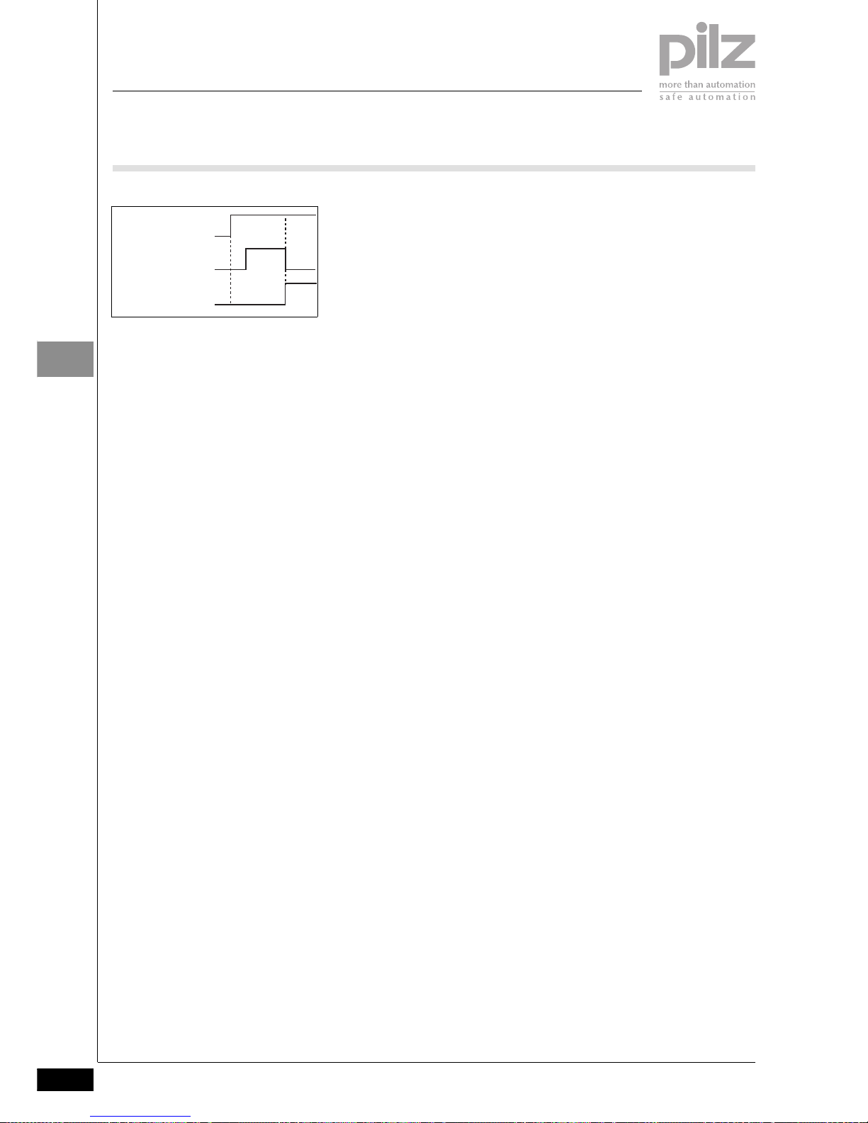
` Automatic reset
With an automatic reset, the output on
the function element goes to “1” when
the safety switches on the input circuit
are closed.
` Manual reset
A N/O contact on the reset input generates the reset signal. The reset button must be operated after the safety
switch has closed. The output on the
input element is set to “1” when the reset button is operated.
` Monitored reset
A N/O contact on the reset input generates the reset signal. The reset button must be operated after the safety
switch has closed. The output on the
input element is set to “1” when the reset button is released.
Reset button
Output
Safety contact
Page 30
Basics
Configuration and Wiring
Inputs
2007-11Pilz GmbH & Co. KG, Sichere Automation, Felix-Wankel-Straße 2, 73760 Ostfildern, Germany
Telephone: +49 711 3409-0, Telefax: +49 711 3409-133, E-Mail: pilz.gmbh@pilz.de
1.4-6
1.4
Test pulses and detection of shorts
across contacts
` Under certain circumstances, sig-
nal inputs with infrequent operation
(constant signals) supply an unchanging signal over a long period
of time. During this time, the function of the periphery devices can
only be monitored to a limited extent. Faults that arise may remain
undetected. Signal inputs with infrequent operation must therefore
be checked via test pulses from
category 2 onwards, in accordance
with EN 954-1.
` Test pulses are assigned to inputs
in the PNOZm Configurator. If “Detection of shorts between contacts
in the input circuit” has been selected, the base unit provides 4 test
pulses.
` Two-hand button: Switch type 6
contains a N/C / N/O combination
per two-hand button.
` If switch type 7 is used, the two N/
O contacts should use different test
pulses.
` Please refer to clause 4 of EN 574
during configuration.
` Detection of shorts between con-
tacts in the reset circuit: Monitored
reset mode will detect a short
across the contacts. For wiring reasons the reset circuit may also use
test pulses.
` Test pulse outputs may only be
used to test the inputs. They must
not be used to drive loads.
` Test pulse outputs are also used to
supply safety mats that trigger a
short circuit.
Where test pulses are used for the
safety mat, they may not be reused
for other purposes.
Safety mats are supported from the
following base unit versions:
– PNOZ m0p: From Version 1.2
– PNOZ m1p: From Version 4.3
– PNOZ m2p: From Version 1.3
Start-up test
` A start-up test is available for the
safety gate and light curtain safety
functions.
` When supply voltage is removed
and then re-applied, the safety gate
is enabled (output on the safety
gate input element = “1”) only after
the gate has been opened and then
closed. In this way you are forced to
check the correct function of the
safety gate and safety gate switch.
` The PNOZmulti switches to a STOP
condition after an error. The PNOZmulti switches back to a RUN condition when the supply voltage has
been switched on and off. For this
reason the start-up test must be
carried out again after each STOP.
Reset button
Output
Safety contact
Page 31

Basics
Pilz GmbH & Co. KG, Sichere Automation, Felix-Wankel-Straße 2, 73760 Ostfildern, Germany
Telephone: +49 711 3409-0, Telefax: +49 711 3409-133, E-Mail: pilz.gmbh@pilz.de
Configuration and Wiring
Logic elements
2006-02
1.4-7
1.4
Logic elements1.42006-02BasicsConfiguration and WiringLogic elementsPNOZmulti zusammengestell te Texte
The functions on the PNOZmulti devices are configured using the PNOZmulti Configurator.
Logic elements affect the state of the
function elements. Logic elements include:
` Logic connections e.g. AND, OR
` Time elements
` Event counter
` Speed monitor
` Start element
` Connection point
` Press elements
` Muting
Logic elements can be linked with
` the outputs of the function ele-
ments
` other logic elements
` the inputs of the output elements
Speed monitor
The speed monitor logic element is
used to configure the PNOZ ms1p/
PNOZ ms2p speed monitor. The
speed monitor monitors
` Standstill
` Overspeed
` Direction of rotation
The following input devices can be
evaluated:
` Incremental encoders (TTL and Sin-
Cos)
` Proximity switches
The following can be configured in the
PNOZmulti Configurator:
` Maximum of 4 PNOZ ms1p speed
monitors
` Maximum of 2 independent axes
per speed monitor
Logic elements for press applications
Press-related logic elements are designed for applications on mechanical
presses.
All the functions required for a press
are available.
These include:
` Operating modes
` Set-up mode
` Single stroke
` Automatic
` Monitoring a rotary cam arrange-
ment
` Run monitoring
` Monitoring electrosensitive protec-
tive equipment (pulse mode)
` Driving and monitoring a press
safety valve
For applications on presses (PNOZ
m2p only), please refer to the chapter
on “Safety solutions for presses” in the
configuration guide “PNOZmulti –
Special applications”. It contains safely guidelines and a detailed example.
Time elements
Due to the cyclical processing, delay
times on time elements may be up to
15 ms longer than the configured value.
Muting
The muting logic element is used to
temporarily suspend the safety functions (ESPE/AOPD) without interrupting the process (muting).
For a limited period of time, and for a
specific operational phase (e.g. when
feeding materials), it will suspend the
effect of safety devices during the
working process. Once completed, it
will reset the safety function.
Performance features:
` Muting via light beam devices or
limit switches
`
Selectable: sequential, parallel or
cross muting
` Ability to override the muting func-
tion if a fault occurs
` Max. muting time can be set
` Time monitoring of the muting sen-
sors
` Suspension of bounce time
Operating modes:
` Sequential muting
` Parallel muting
` Cross muting
The muting application is described in
detail in the configuration guide under
“Special applications”.
Page 32

Basics
Configuration and Wiring
Outputs
2006-02Pilz GmbH & Co. KG, Sichere Automation, Felix-Wankel-Straße 2, 73760 Ostfildern, Germany
Telephone: +49 711 3409-0, Telefax: +49 711 3409-133, E-Mail: pilz.gmbh@pilz.de
1.4-8
1.4
Outputs1.42006-02BasicsConfiguration and WiringOutputsPNOZmulti zusa mmengestellte Texte
Connection options
Depending on the unit type, the following may be connected to the outputs
on the PNOZmulti:
` Relays
` Contactors
` Valves
` Signal lamps
The PNOZmulti has outputs for both
safety-related and standard applications.
` Only safety outputs should be used
for safety-related applications.
` Outputs for standard functions may
be used for a signal lamp, for example.
Configuration in the PNOZmulti
Configurator
The outputs on the PNOZmulti units
are configured in the PNOZmulti Configurator.
For example, you can define the following:
` Relays
` Semiconductors
` Valve control
` Feedback loop
` Output for standard function
Some configuration options can only
be selected for specific safety functions (e.g. single, double or directional
valve)
Switch-off delay
When establishing the reaction time of
the safety device, the switch-off delay
on the outputs must be taken into account (see Technical details). The
switch-off delay indicates the time between the safety function on the input
of the PNOZmulti unit being triggered
and the output contacts switching
over / the semiconductor outputs carrying a low signal.
Relay
The relay contacts meet the requirements for safe separation through increased insulation compared with all
other circuits in the safety system.
Single-channel or redundant relay outputs are available. The redundant outputs are suitable for applications with
a higher level of safety (for wiring options please see the chapter entitled
“Units”).
2-channel operation of loads
` Loads should be driven through 2
separate channels or, in the case of
redundant relay outputs, shorts
across contacts should be prevent-
ed e.g. by installing the safety sys-
tem and its loads (contactors) in a
control cabinet.
` In terms of load on the relays, keep
to the max. permitted operations
stated in the technical details.
Semiconductor
Single-channel or redundant semiconductor outputs are available. The redundant outputs are suitable for
applications with a higher level of safety (for wiring options please see the
chapter entitled “Units”).
Feedback loop
` The feedback loop is used to moni-
tor the actuators that are being driv-
en.
` On a feedback loop, positive-guid-
ed N/C contacts on the driven con-
tactors (actuators) are connected in
series. If 24 VDC are present at the
input on the feedback loop, all the
connected contactors are de-ener-
gised. If the N/O contact on a con-
tactor has welded, the feedback
loop is not closed when switching
off. The safety output will not be
switched if the feedback loop is in-
terrupted.
The PNOZmulti registers an error in
the following cases:
` The output is switched on and 24
VDC is not present at the input on
the feedback loop.
` The feedback loop remains closed
for longer than 3 seconds (24 V on
the feedback loop input) after the
output was switched on.
In both cases, the output will switch off
and the error will be entered in the error stack. The “OFAULT” LED flashes.
The error is reset by switching off the
output.
Contactor with positive-guided contacts
Only contactors with positive-guided
contacts should be used on the
PNOZmulti's safety outputs.
Page 33

Basics
Pilz GmbH & Co. KG, Sichere Automation, Felix-Wankel-Straße 2, 73760 Ostfildern, Germany
Telephone: +49 711 3409-0, Telefax: +49 711 3409-133, E-Mail: pilz.gmbh@pilz.de
Configuration and Wiring
Inputs and outputs for standard functions
2006-02
1.4-9
1.4
Inputs and outputs for standard functions1.42006-02BasicsConfiguration and WiringInputs and outputs for standard functions
Inputs
Inputs for standard functions may be
` Inputs for standard functions from
units in the PNOZmulti-range
` 24 inputs for standard functions
which are transmitted via the fieldbus
` 24 virtual inputs for standard func-
tions which are transmitted via the
serial interface
` Results of logic operations (RLO =
0, RLO = 1)
Inputs for standard functions may only
be used in the PNOZmulti Configurator
` As a reset button for
– the function elements E-STOP,
safety gate and light curtain
– the reset logic element
` As an input for an AND connection,
which also has an additional safe
input
` As a reset or acknowledgement
button on logic elements
` As an input for a non-safety-related
output element (e.g. non-safety-re-
lated semiconductor outputs)
` As a direct connection to a fieldbus
output
Outputs
Outputs for standard functions may be
` Outputs for standard functions from
units in the PNOZmulti-range
` 24 outputs for standard functions
which are transmitted via the field-
bus
` 24 virtual outputs for standard
functions which are transmitted via
the serial interface
Use
Inputs and outputs for standard functions must not be used for safety-related applications.
Examples in the PNOZmulti Configurator
ST: Input or output for standard functions
FS: Input or output for safety functions
` Reset button on function elements
` AND connection
` Acknowledgement on reset ele-
ment
` Direct connection of inputs and
outputs for standard functions
` Input for driving an output for
standard functions
ST
FS
FS
ST
ST
FS
FS
ST
FS
FS
ST ST
ST
ST
Page 34

Basics
Configuration and Wiring
Cascading
2008-08Pilz GmbH & Co. KG, Sichere Automation, Felix-Wankel-Straße 2, 73760 Ostfildern, Germany
Telephone: +49 711 3409-0, Telefax: +49 711 3409-133, E-Mail: pilz.gmbh@pilz.de
1.4-10
1.4
Cascading1.42008- 08BasicsConfiguration and WiringCascadingPNO Zmulti zusammengest ellte Texte
` Base units on the modular safety
system can be networked. The cas-
cading output on one base unit is
connected to the cascading input
on another base unit. In this way,
one base unit can have direct ac-
cess to a logic output and/or an in-
put on the connected base unit.
` The base units can be connected in
series or a tree structure can be
built.
` PNOZelog units may also be includ-
ed in the network.
` The cascading outputs may not be
used to drive loads. The same also
applies to outputs on PNOZelog
units that are connected to cascading inputs on PNOZmulti units.
` If necessary, a reset lock must be
provided on each cascaded unit.
System requirements
PNOZmulti Configurator: from Version
3.0.0
Please contact Pilz if you have an older
version.
Series connection
As many PNOZ m1p base units as
necessary may be connected in series.
The number of units connected in succession will depend only on the reaction time required by the application.
As the delay times on the individual
units are added together, the reaction
time increases with each unit.
CI+
CI-
CO+
CO-
PNOZ m1p
Unit 1
CI+
CI-
CO+
CO-
PNOZ m1p
Unit 2
CI+
CI-
CO+
CO-
PNOZ m1p
Unit x
Delay time on the PNOZmulti Switch-off delay Switch-on delay
Between input and cascading output Max. 40 ms Typ. 100 ms
Between cascading input and a semicon-
ductor output
Max. 40 ms Typ. 100 ms
Between cascading input and a relay output
Max. 60 ms Typ. 120 ms
Between cascading input and a cascading
output
Max. 40 ms Typ. 120 ms
Page 35

Basics
Pilz GmbH & Co. KG, Sichere Automation, Felix-Wankel-Straße 2, 73760 Ostfildern, Germany
Telephone: +49 711 3409-0, Telefax: +49 711 3409-133, E-Mail: pilz.gmbh@pilz.de
Configuration and Wiring
Cascading
2008-08
1.4-11
1.4
Example:
` Delay between input I0 - cascading
output Unit 1: 40 ms
` Delay between input I0 - cascading
output Unit 2: 40 ms + 40 ms
` Delay between input I0 - semicon-
ductor output Unit 3: 40 ms + 40 ms
+ 40 ms
` Delay between input I0 - relay out-
put Unit 4: 40 ms + 40 ms + 40 ms
+ 60 ms
Incorporating PNOZelog units:
` PNOZelog units may also be includ-
ed in the series connection. The de-
lay times on the individual units are
also added together with this type
of cascading.
` Remember to consider the switch-
on delay and any potential delay
time for the outputs on the
PNOZelog units (see operating
manual or PNOZelog technical catalogue).
` When connecting PNOZmulti -
PNOZelog, the cascading output
“CO-” is not connected.
I0 CO+
CO-
PNOZ m1p
Unit 1
CI+
CI-
CO+
CO-
PNOZ m1p
Unit 2
CI+
CI-
CO+
CO-
PNOZ m1p
Unit 3
CI+
CI-
O4
PNOZ m1p
Unit 4
N
O0
L-
L+
S1
14
13
L
CI+
CI-
CO+
A2
S36 (S35)
A2
14
(24)
A2
PNOZ m1p PNOZelog
Unit 1 Unit 2
CI+
CI-
CO+
A2
PNOZ m1p
Unit 3
S36 (S35)
A2
14
(24)
A2
PNOZelog
Unit 4
Page 36

Basics
Configuration and Wiring
Cascading
2008-08Pilz GmbH & Co. KG, Sichere Automation, Felix-Wankel-Straße 2, 73760 Ostfildern, Germany
Telephone: +49 711 3409-0, Telefax: +49 711 3409-133, E-Mail: pilz.gmbh@pilz.de
1.4-12
1.4
Tree structure
` Tree structures may be designed
with as many levels as necessary.
Conditions:
` A max. of 4 PNOZmulti units may
be incorporated in parallel on each
level.
` PNOZelog units may only be con-
nected to the PNOZmulti units in
series. Max. of one PNOZelog unit
is permitted on each level.
CI+
CI-
CO+ CO-
PNOZ m1p
S36 (S35)
A2
14 (24) A2
PNOZelog
CI+
CI-
CO+ A2
PNOZ m1p
CI+
CI-
CO+ CO-
PNOZ m1p
CI+
CI-
CO+ CO-
PNOZ m1p
CI+
CI-
CO+ CO-
PNOZ m1p
CI+
CI-
CO+ CO-
PNOZ m1p
CI+
CI-
CO+ CO-
PNOZ m1p
CI+
CI-
CO+ CO-
PNOZ m1p
CI+
CI-
CO+ CO-
PNOZ m1p
CI+
CI-
CO+ CO-
PNOZ m1p
S36 (S35)
A2
14 (24) A2
PNOZelog
Page 37

Basics
Pilz GmbH & Co. KG, Sichere Automation, Felix-Wankel-Straße 2, 73760 Ostfildern, Germany
Telephone: +49 711 3409-0, Telefax: +49 711 3409-133, E-Mail: pilz.gmbh@pilz.de
Configuration and Wiring
Cascading
2008-08
1.4-13
1.4
Supply voltage for the cascaded
units
` The cascaded PNOZmulti units
may be supplied via a power sup-
ply. The power consumption of the
individual units should be consid-
ered when deciding on the size of
the power supply.
` Cascaded PNOZelog units and all
PNOZmulti units connected directly
to PNOZelog units must be sup-
plied via a common power supply.
The voltage tolerance on the power
supply may be a maximum of +20%
or -10%.
Installing the cascaded units
` If PNOZmulti units alone are being
networked, the networked units
may be housed in separate control
cabinets.
` If PNOZelog units are integrated
into the network, these PNOZelog
units and their cascade cables must
always be housed in the same control cabinet as the PNOZmulti units
that are connected directly to the
PNOZelog units.
Wiring
Please observe the following when
wiring:
` Cable runs between the connected
units:
` PNOZmulti - PNOZmulti: max. 100
m
` PNOZelog - PNOZmulti cascaded
directly: max. 10 m
` Cable material: see technical de-
tails
` Outside the control cabinet, both
the wires from the cascading input
(CI+, CI-) and the wires from the
cascading output (CO+, CO-) must
be laid in separate multicore cables.
S36 (S35)
A2
14 (24) A2
PNOZelog
CI+
CI-
CO+ CO-
PNOZ m1p
CI+
CI-
CO+ CO-
PNOZ m1p
Power
A2
A1
A1
A1
A2
Page 38

Products
Pilz GmbH & Co. KG, Sichere Automation, Felix-Wankel-Straße 2, 73760 Ostfildern, Germany
Telephone: +49 711 3409-0, Telefax: +49 711 3409-133, E-Mail: pilz.gmbh@pilz.de
2.0-0
2.0
Products2.0
Page 39

Products
Pilz GmbH & Co. KG, Sichere Automation, Felix-Wankel-Straße 2, 73760 Ostfildern, Germany
Telephone: +49 711 3409-0, Telefax: +49 711 3409-133, E-Mail: pilz.gmbh@pilz.de
2008-03
2.0-1
2.0
Contents Page
Selection guide from 2.1-1
Base units from 2.2-1
Expansion modules from 2.3-1
Adapter for PNOZ ms1p and PNOZ ms2p from 2.4-1
Software from 2.5-1
Page 40

Products
Selection guide
Pilz GmbH & Co. KG, Sichere Automation, Felix-Wankel-Straße 2, 73760 Ostfildern, Germany
Telephone: +49 711 3409-0, Telefax: +49 711 3409-133, E-Mail: pilz.gmbh@pilz.de
2.1-0
2.1
ProductsSelection guide2.1
Page 41

Products
Pilz GmbH & Co. KG, Sichere Automation, Felix-Wankel-Straße 2, 73760 Ostfildern, Germany
Telephone: +49 711 3409-0, Telefax: +49 711 3409-133, E-Mail: pilz.gmbh@pilz.de
Selection guide
2008-03
2.1-1
2.1
Contents Page
Selection guide
Base units and expansion modules 2.1-2
Fieldbus modules 2.1-3
Page 42

Products
Selection guide
Base units and expansion modules
2008-03Pilz GmbH & Co. KG, Sichere Automation, Felix-Wankel-Straße 2, 73760 Ostfildern, Germany
Telephone: +49 711 3409-0, Telefax: +49 711 3409-133, E-Mail: pilz.gmbh@pilz.de
2.1-2
2.1
Base units and expansion modules2.12007-11ProductsSelect ion guideBase units and expansion modules
Type
Inputs
Safe
Inputs
Standard
Inputs
Virtual
Inputs
Speed
Safe
Outputs
Semiconductor
Safe
1-pole
Outputs
Semiconductor
Safe
2-pole
Outputs
Semiconductor
Standard
Outputs
Relay
Safe
Outputs
Virtual
Expansion modules
Max.
number
PNOZ m0p 20 4 1 2 1 field-
bus module
PNOZ m1p 20 4 1 2 12 + 1
fieldbus
module
PNOZ m2p 20 4 1 2 12 + 1
fieldbus
module
PNOZ ma1p 2 ana-
logue
4
PNOZ mc1p 16 8
PNOZ mi1p 8 8
PNOZ mi2p 8 8
PNOZ ml1p 32 32 4
PNOZ mo1p 4 6
PNOZ mo2p 2 6
PNOZ mo3p 2 6
PNOZ mo4p 4 6
PNOZ ms1p 2 4
PNOZ ms2p 2 4
Page 43

Products
Pilz GmbH & Co. KG, Sichere Automation, Felix-Wankel-Straße 2, 73760 Ostfildern, Germany
Telephone: +49 711 3409-0, Telefax: +49 711 3409-133, E-Mail: pilz.gmbh@pilz.de
Selection guide
Fieldbus modules
2008-03
2.1-3
2.1
Fieldbus modules2.12007-11ProductsSelec tion guideFieldbus modules
Type
Fieldbus
Fieldbus modules
Max.
number
PNOZ mc3p PROFIBUS-DP 1
PNOZ mc4p DeviceNet 1
PNOZ mc5p Interbus 1
PNOZ mc5.1p Interbus fibre-optic cable 1
PNOZ mc6p CANopen 1
PNOZ mc7p CC-Link 1
PNOZ mc8p Ethernet IP/Modbus TCP 1
PNOZ mc9p PROFINET 1
Page 44

Products
Base units
Pilz GmbH & Co. KG, Sichere Automation, Felix-Wankel-Straße 2, 73760 Ostfildern, Germany
Telephone: +49 711 3409-0, Telefax: +49 711 3409-133, E-Mail: pilz.gmbh@pilz.de
2.2-0
2.2
ProductsBase units2.2
Page 45

Products
Pilz GmbH & Co. KG, Sichere Automation, Felix-Wankel-Straße 2, 73760 Ostfildern, Germany
Telephone: +49 711 3409-0, Telefax: +49 711 3409-133, E-Mail: pilz.gmbh@pilz.de
Base units
2008-03
2.2-1
2.2
Contents Page
Base units
PNOZ m0p 2.2-2
PNOZ m1p 2.2-11
PNOZ m1p coated version 2.2-20
PNOZ m2p 2.2-29
Page 46

Products
Base units
PNOZ m0p
NSG-D-2-358-2007-09Pilz GmbH & Co. KG, Sichere Automation, Felix-Wankel-Straße 2, 73760 Ostfildern, Germany
Telephone: +49 711 3409-0, Telefax: +49 711 3409-133, E-Mail: pilz.gmbh@pilz.de
2.2-2
2.2
PNOZ m0p2.2NSG-D-2-35 8-2007-09ProductsBase unitsPNOZ m 0pPNOZ m0p
Base units from the PNOZmulti modular safety system
Approvals
Unit features
` Can be configured in the PNOZmul-
ti Configurator
` Positive-guided relay outputs:
– 1 safety output in accordance
with EN 954-1, Cat. 4
or 2 safety outputs in accordance with EN 954-1, Cat. 2
` Semiconductor outputs:
– 2 safety outputs in accordance
with EN 954-1, Cat. 4
or 4 safety outputs in accordance with EN 954-1, Cat. 3
– 1 auxiliary output
` 4 test pulse outputs
` 1 cascading input and output; can
also be used as a standard output
` 20 inputs for connecting:
– E-STOP pushbutton
– Two-hand button
– Safety gate limit switch
– Reset button
– Light beam devices
– Scanner
– Enable switch
– PSEN
– Operating mode selector switch
– Safety mats
` Muting function
` Connectable:
– 1 fieldbus module on the left
– 4 expansion modules on the left
` LED for:
– Diagnostics
– Supply voltage
– Output circuits
– Input circuits
` Test pulse outputs used to detect
shorts across the inputs
` Monitoring of shorts between the
safety outputs
` Plug-in connection terminals (either
cage clamp terminal or screw terminal)
Unit description
The PNOZmulti modular safety system
is used for the safety-related interruption of safety circuits and is designed
for use on:
` Emergency stop equipment
` Safety circuits in accordance with
VDE 0113 Part 1 and EN 60204-1
Chip card
Chip cards are available with memories of 8 kByte and 32 kByte. For largescale projects we recommend the 32
kByte chip card (see chapter containing the order references).
Safety features
The relay conforms to the following
safety criteria:
` The circuit is redundant with built-in
self-monitoring.
` The safety function remains effec-
tive in the case of a component failure.
` The relay contacts meet the re-
quirements for safe separation
through increased insulation compared with all other circuits in the
safety system.
` The safety outputs are tested peri-
odically using a disconnection test.
PNOZ m0p
Page 47

Products
Pilz GmbH & Co. KG, Sichere Automation, Felix-Wankel-Straße 2, 73760 Ostfildern, Germany
Telephone: +49 711 3409-0, Telefax: +49 711 3409-133, E-Mail: pilz.gmbh@pilz.de
Base units
PNOZ m0p
NSG-D-2-358-2007-09
2.2-3
2.2
Block diagram
=
Power
Input
A1 A2
Test pulse
output
I0 I19I1 I2 I3 I8I5
I11
I4 I9 I12 I13 I14 I15 I16 I17I7 I18I6
I10
O4
=
CI+ CI- CO-
CO+
T3T0
O2
O0
24 V0 V
T2T1
O1
Cascading
OA0
O3
24 V 0 V
Interface
chip card
Interface
diagnostic
module
RS 232
13 23
14 24
O5
Page 48

Products
Base units
PNOZ m0p
NSG-D-2-358-2007-09Pilz GmbH & Co. KG, Sichere Automation, Felix-Wankel-Straße 2, 73760 Ostfildern, Germany
Telephone: +49 711 3409-0, Telefax: +49 711 3409-133, E-Mail: pilz.gmbh@pilz.de
2.2-4
2.2
Function description
The function of the inputs and outputs
on the safety system depends on the
safety circuit created using the PNOZmulti Configurator. A chip card is used
to download the safety circuit to the
base unit. The base unit has 2 microcontrollers that monitor each other.
They evaluate the input circuits on the
base unit and expansion modules and
switch the outputs on the base unit
and expansion modules accordingly.
The online help on the PNOZmulti
Configurator contains descriptions of
the operating modes and all the functions of the PNOZmulti safety system,
plus connection examples.
Wiring
The wiring is defined in the circuit diagram in the Configurator. There you
can select the inputs that are to perform a particular safety function and
the outputs that will switch this safety
function.
Please note:
` Information given in the "Technical
details" must be followed.
` Outputs:
– O0 to O5 are safety outputs.
– O4 and O5 are relay outputs
– O0 to O3 are semiconductor out-
puts
– OA0 is an auxiliary output.
` To prevent contact welding, a fuse
should be connected before the
output contacts (see technical de-
tails).
` Use copper wire that can withstand
75 °C.
` Sufficient fuse protection must be
provided on all output contacts with
inductive loads.
` Power for the safety system and in-
put circuits must always be provid-
ed from a single power supply. The
power supply must meet the regu-
lations for extra low voltages with
safe separation.
` Two connection terminals are avail-
able for each of the supply connec-
tions 24 V and 0 V (semiconductor
outputs), plus A1 and A2 (power
supply). This means that the supply
voltage can be looped through sev-
eral connections. The current at
each terminal may not exceed 9 A.
` Test pulse outputs must exclusively
be used to test the inputs. They
must not be used to drive loads.
Do not route the test pulse lines together with actuator cables within
an unprotected multicore cable.
` Test pulse outputs are also used to
supply safety mats that trigger a
short circuit.
Where test pulses are used for the
safety mat, they may not be reused
for other purposes.
Safety mats are supported from
Version 1.2 of the base unit.
Page 49
Products
Pilz GmbH & Co. KG, Sichere Automation, Felix-Wankel-Straße 2, 73760 Ostfildern, Germany
Telephone: +49 711 3409-0, Telefax: +49 711 3409-133, E-Mail: pilz.gmbh@pilz.de
Base units
PNOZ m0p
NSG-D-2-358-2007-09
2.2-5
2.2
Preparing for operation
` Supply voltage
Connection examples:
` Input circuit
` Reset circuit
Supply voltage AC DC
For the safety system
(connector X7)
For the semiconductor outputs
(connector X2)
Must always be present, even if the semiconductor outputs are not used
A1
+ 24 V DC
A2
0 V
24 V
+ 24 V DC
0 V
0 V
Input circuit Single-channel Dual-channel
Example:
E-STOP
without detection of shorts across contacts
Example:
E-STOP
with detection of shorts across contacts
S1
I0
L+
S1
I1
I0
L+
L+
I0
T0
S1
S1
T1
I1
T0
I0
Reset circuit Input circuit without detection of shorts
across contacts
Input circuit with detection of shorts across
contacts
Monitored reset
I5
S3
L+
I5
T0
S3
Page 50

Products
Base units
PNOZ m0p
NSG-D-2-358-2007-09Pilz GmbH & Co. KG, Sichere Automation, Felix-Wankel-Straße 2, 73760 Ostfildern, Germany
Telephone: +49 711 3409-0, Telefax: +49 711 3409-133, E-Mail: pilz.gmbh@pilz.de
2.2-6
2.2
` Semiconductor outputs
` Relay outputs
` Feedback loop
` Key
Redundant output
Single output
K2
L-
O0 (O2)
O1 (O3)
K1
L-
K3
L-
K4
O0 (O2)
O1 ( O3)
K1
L-
K2
Redundant
Single
O5
K1
L1
N
K2
14
13
23
24
O4
O5
K1
L1
N
K2
14
13
23
24
O4
Feedback loop Redundant output
Contacts from external contactors
K1
L+
L-
K2
O0 (O2, O4)
O1 (O3, O5)
I0
L-
S1 E-STOP pushbutton
S3 Reset button
Page 51

Products
Pilz GmbH & Co. KG, Sichere Automation, Felix-Wankel-Straße 2, 73760 Ostfildern, Germany
Telephone: +49 711 3409-0, Telefax: +49 711 3409-133, E-Mail: pilz.gmbh@pilz.de
Base units
PNOZ m0p
NSG-D-2-358-2007-09
2.2-7
2.2
Terminal configuration
Installation
` The safety system should be in-
stalled in a control cabinet with a
protection type of at least IP54. Fit
the safety system to a horizontal
DIN rail. The venting slots must face
upward and downward. Other
mounting positions could damage
the safety system.
` Use the notches on the back of the
unit to attach it to a DIN rail. Con-
nect the safety system to the DIN
rail in an upright position, so that
the earthing springs on the safety
system are pressed on to the DIN
rail.
` To comply with EMC requirements,
the DIN rail must have a low imped-
ance connection to the control cab-
inet housing.
Dimensions
CHIP-Card
0
94 (3.70")
121 (4.76")
135 (5.31")
Page 52

Products
Base units
PNOZ m0p
NSG-D-2-358-2007-09Pilz GmbH & Co. KG, Sichere Automation, Felix-Wankel-Straße 2, 73760 Ostfildern, Germany
Telephone: +49 711 3409-0, Telefax: +49 711 3409-133, E-Mail: pilz.gmbh@pilz.de
2.2-8
2.2
Notice
This data sheet is only intended for use
during configuration. For installation
and operation, please refer to the operating instructions supplied with the
unit.
Service life graph
Maximum capacitive load C (μF)
with load current I (mA) at the semiconductor outputs
10
1
10 100 1000 10000
0.1
DC1: 24 V
AC1: 230 V
DC13: 24 V
AC15: 230 V
D Nennbetriebstrom (A)
GB Nominal operating current (A)
F Courant coupé (A)
E Corriente nominal de servicio (A)
I Corrente di esercizio nominale (A)
NL Nominale bedrijfsstroom (A)
D Schaltspielzahl x 10
3
GB Cycles x 10
3
F Nombre de manuvres x 10
3
E Número de ciclos x 10
3
I Numero dei cicli di commutazione x 10
3
NL Aantal schakelingen x 10
3
2
4
0
0 10 50 100 200 400 600 800
1000
1200 I (mA)
6
1400 1600 1800 2000
C (µF)
Technical details
Electrical data
Supply voltage (UB) 24 VDC
Voltage tolerance -15% ... 10%
Power consumption at U
B
without load Max. 8.0 W + 2.5 W per expansion module
Residual ripple U
B
+/- 5 %
Times
Switch-on delay 5 s (after UB is applied)
Simultaneity channel 1/2/3 3 s, two-hand control relay: 0.5 s
Supply interruption before de-energisation Min. 20 ms
Inputs
Quantity 20
Voltage and current 24 VDC/8 mA
Galvanic isolation
Cascading input
No
500 VAC
Page 53

Products
Pilz GmbH & Co. KG, Sichere Automation, Felix-Wankel-Straße 2, 73760 Ostfildern, Germany
Telephone: +49 711 3409-0, Telefax: +49 711 3409-133, E-Mail: pilz.gmbh@pilz.de
Base units
PNOZ m0p
NSG-D-2-358-2007-09
2.2-9
2.2
Signal level at “0” -3 ... +5 VDC
Signal level at “1” 15 ... 30 VDC
Input delay 0.6 ... 4 ms
Status indicator LED
Test pulse outputs
Quantity 4
Voltage and current 24 VDC / 0.5 A
Off time during self test < 5 ms
Galvanic isolation No
Short circuit protection Yes
Status indicator LED
Semiconductor outputs
Quantity
For EN 954-1, 12/96, Cat. 4
For EN 954-1, 12/96, Cat. 3
2
4
Switching capability 24 VDC / max. 2 A / max. 48 W
Max. capacitive load See diagram
External supply voltage (U
B
) 24 VDC
Voltage tolerance -15% - 10%
Off time during self test < 300 μs
Galvanic isolation Yes
Short circuit protection Yes
Switch-off delay < 30 ms
Residual current at "0" < 0.5 mA
Signal level at “1” U
B
- 0.5 VDC at 2 A
Status indicator LED
Relay outputs
Quantity
For EN 954-1, 12/96, Cat. 4
For EN 954-1, 12/96, Cat. 2
1
2
Utilisation category in accordance with
EN 60947-4-1, 02/01
EN 60947-5-1, 11/97
AC1: 240 V / 6 A / 1440 VA
DC1: 24 V / 6 A / 144 W
AC15: 230 V / 3 A / 690 VA
DC13: 24 V / 3 A / 72 W
Contact fuse protection in accordance with EN 60947-5-1, 08/00
Blow-out fuse
Circuit breaker 24 VDC
6 A quick or slow
6 A (characteristic B + C)
Switch-off delay 50 ms
Status indicator LED
Auxiliary outputs
Quantity 1
Voltage and current 24 VDC / max. 0.5 A / max. 12 W
External supply voltage (U
B
) 24 VDC
Voltage tolerance -15% ... +10%
Galvanic isolation Yes
Short circuit protection Yes
Residual current at "0" < 0.5 mA
Signal level at “1” U
B
- 0.5 VDC at 0.5 A
Status indicator LED
Cascading output as auxiliary output
Quantity 1
Voltage and current 24 VDC / max. 0.2 A / max. 4.8 W
Galvanic isolation No
Short circuit protection Yes
Residual current at "0" < 0.5 mA
Inputs
Page 54

Products
Base units
PNOZ m0p
NSG-D-2-358-2007-09Pilz GmbH & Co. KG, Sichere Automation, Felix-Wankel-Straße 2, 73760 Ostfildern, Germany
Telephone: +49 711 3409-0, Telefax: +49 711 3409-133, E-Mail: pilz.gmbh@pilz.de
2.2-10
2.2
Environmental data
Airgap creepage between
relay contacts
Relay contacts and other safe circuits
DIN VDE 0110-1, 04/97
3 mm
5.5 mm
Vibration in accordance with EN 60068-2-6, 04/95
Frequency:
Amplitude:
10 ... 55 Hz
0.35 mm
Climatic suitability DIN IEC 60068-2-3, 12/86
EMC EN 60947-5-1, 01/00
Ambient temperature
With UL approval
Without UL approval (with forced convection)
0 ... +55 °C
0 ... +60 °C
Storage temperature -25 ... +70 °C
Mechanical data
Protection type
Mounting (e.g. cabinet)
Housing
Terminals
IP54
IP20
IP20
DIN rail
Top hat rail
Recess width
35 x 7.5 EN 50022
27 mm
Maximum cable runs
Per input
Sum of individual cable runs at the test pulse output
1 km
40 km
Cross section of external conductors
Rigid single-core, flexible multi-core or multi-core
With crimp connector
Power supply (X7), inputs (X5, X6), semiconductor outputs (X2), test
pulse outputs (X1)
auxiliary output (X2), cascading output
Relay outputs (X3)
Flexible multi-core with plastic sleeve
Relay outputs (X3)
0.5 ... 1.5 mm
2
0.5 ... 2.5 mm
2
0.5 ... 1.5 mm
2
Torque setting for connection terminals (screws)
Power supply (X7), inputs (X5, X6), semiconductor outputs (X2), test
pulse outputs (X1),
auxiliary output (X2), cascading output
Relay outputs (X3)
0.2 ... 0.25 Nm
0.4 ... 0.5 Nm
Housing material
Housing
Front
PPO UL 94 V0
ABS UL 94 V0
Dimensions (H x W x D) 94 x 135 x 121 mm
Weight with connector 530 g
Order reference
Type Features Order no.
PNOZ m0p Base unit 773 110
Page 55

Products
Pilz GmbH & Co. KG, Sichere Automation, Felix-Wankel-Straße 2, 73760 Ostfildern, Germany
Telephone: +49 711 3409-0, Telefax: +49 711 3409-133, E-Mail: pilz.gmbh@pilz.de
Base units
PNOZ m1p
NSG-D-2-359-2007-09
2.2-11
2.2
PNOZ m1p2.2NSG-D-2-35 9-2007-09ProductsBase unitsPNOZ m 1pPNOZ m1p
Base units from the PNOZmulti modular safety system
Approvals
Unit features
` Can be configured in the PNOZmul-
ti Configurator
` Positive-guided relay outputs:
– 1 safety output in accordance
with EN 954-1, Cat. 4
or 2 safety outputs in accordance with EN 954-1, Cat. 2
` Semiconductor outputs:
– 2 safety outputs in accordance
with EN 954-1, Cat. 4
or 4 safety outputs in accordance with EN 954-1, Cat. 3
– 1 auxiliary output
` 4 test pulse outputs
` 1 cascading input and output
can also be used as a standard output
` 20 inputs for connecting:
– E-STOP pushbutton
– Two-hand button
– Safety gate limit switch
– Reset button
– Light beam devices
– Scanner
– Enable switch
– PSEN
– Operating mode selector switch
– Safety mats
` Muting function
` Connectable:
– 8 expansion modules on the
right
– 1 fieldbus module on the left
– 4 expansion modules on the left
` LED for:
– Diagnostics
– Supply voltage
– Output circuits
– Input circuits
` Test pulse outputs used to detect
shorts across the inputs
` Monitoring of shorts between the
safety outputs
` Plug-in connection terminals (either
cage clamp terminal or screw terminal)
Unit description
The PNOZmulti modular safety system
is used for the safety-related interruption of safety circuits and is designed
for use on:
` Emergency stop equipment
` Safety circuits in accordance with
VDE 0113 Part 1 and EN 60204-1
Chip card
Chip cards are available with memories of 8 kByte and 32 kByte. For largescale projects we recommend the 32
kByte chip card (see chapter containing the order references).
The chip card with a memory of 32
kByte can only be used from
PNOZ m1p Version 2.0.
Safety features
The relay conforms to the following
safety criteria:
` The circuit is redundant with built-in
self-monitoring.
` The safety function remains effec-
tive in the case of a component failure.
` The relay contacts meet the re-
quirements for safe separation
through increased insulation compared with all other circuits in the
safety system.
` The safety outputs are tested peri-
odically using a disconnection test.
PNOZ m1p
Page 56

Products
Base units
PNOZ m1p
NSG-D-2-359-2007-09Pilz GmbH & Co. KG, Sichere Automation, Felix-Wankel-Straße 2, 73760 Ostfildern, Germany
Telephone: +49 711 3409-0, Telefax: +49 711 3409-133, E-Mail: pilz.gmbh@pilz.de
2.2-12
2.2
Block diagram
=
Power
Input
A1 A2
Test pulse
output
I0 I19I1 I2 I3 I8I5
I11
I4 I9 I12 I13 I14 I15 I16 I17I7 I18I6
I10
O4 O5
=
CI+ CI- CO+
CO-
T3T0
O2
O0
24 V0 V
T2T1
O1
Cascading
OA0
O3
24 V 0 V
Interface
chip card
Interface
diagnostic
module
RS 232
Interface
expansion
module
13 23
14 24
Page 57

Products
Pilz GmbH & Co. KG, Sichere Automation, Felix-Wankel-Straße 2, 73760 Ostfildern, Germany
Telephone: +49 711 3409-0, Telefax: +49 711 3409-133, E-Mail: pilz.gmbh@pilz.de
Base units
PNOZ m1p
NSG-D-2-359-2007-09
2.2-13
2.2
Function description
The function of the inputs and outputs
on the safety system depends on the
safety circuit created using the PNOZmulti Configurator. A chip card is used
to download the safety circuit to the
base unit. The base unit has 2 microcontrollers that monitor each other.
They evaluate the input circuits on the
base unit and expansion modules and
switch the outputs on the base unit
and expansion modules accordingly.
The online help on the PNOZmulti
Configurator contains descriptions of
the operating modes and all the functions of the PNOZmulti safety system,
plus connection examples.
Wiring
The wiring is defined in the circuit diagram in the Configurator. There you
can select the inputs that are to perform a particular safety function and
the outputs that will switch this safety
function.
Please note:
` Information given in the "Technical
details" must be followed.
` Outputs:
– O0 to O5 are safety outputs.
– O4 and O5 are relay outputs
– O0 to O3 are semiconductor out-
puts
– OA0 is an auxiliary output.
` To prevent contact welding, a fuse
should be connected before the
output contacts (see technical details).
` Use copper wire that can withstand
75 °C.
` Sufficient fuse protection must be
provided on all output contacts with
inductive loads.
` Power for the safety system and in-
put circuits must always be provided from a single power supply. The
power supply must meet the regulations for extra low voltages with
safe separation.
` Two connection terminals are avail-
able for each of the supply connections 24 V and 0 V (semiconductor
outputs), plus A1 and A2 (power
supply). This means that the supply
voltage can be looped through several connections. The current at
each terminal may not exceed 9 A.
` Test pulse outputs must exclusively
be used to test the inputs. They
must not be used to drive loads.
Do not route the test pulse lines together with actuator cables within
an unprotected multicore cable.
` Test pulse outputs are also used to
supply safety mats that trigger a
short circuit.
Where test pulses are used for the
safety mat, they may not be reused
for other purposes.
Safety mats are supported from
Version 4.3 of the base unit.
Page 58

Products
Base units
PNOZ m1p
NSG-D-2-359-2007-09Pilz GmbH & Co. KG, Sichere Automation, Felix-Wankel-Straße 2, 73760 Ostfildern, Germany
Telephone: +49 711 3409-0, Telefax: +49 711 3409-133, E-Mail: pilz.gmbh@pilz.de
2.2-14
2.2
Preparing for operation
` Supply voltage
Connection examples
` Input circuit
` Reset circuit
Supply voltage AC DC
For the safety system
(connector X7)
For the semiconductor outputs
(connector X2)
Must always be present, even if the semiconductor outputs are not used
A1
+ 24 V DC
A2
0 V
24 V
+ 24 V DC
0 V
0 V
Input circuit Single-channel Dual-channel
E-STOP
without detection of shorts across contacts
E-STOP
with detection of shorts across contacts
S1
I0
L+
S1
I1
I0
L+
L+
I0
T0
S1
S1
T1
I1
T0
I0
Reset circuit Input circuit without detection of shorts
across contacts
Input circuit with detection of shorts across
contacts
I5
S3
L+
I5
T0
S3
Page 59

Products
Pilz GmbH & Co. KG, Sichere Automation, Felix-Wankel-Straße 2, 73760 Ostfildern, Germany
Telephone: +49 711 3409-0, Telefax: +49 711 3409-133, E-Mail: pilz.gmbh@pilz.de
Base units
PNOZ m1p
NSG-D-2-359-2007-09
2.2-15
2.2
` Semiconductor outputs
` Relay outputs
` Feedback loop
` Key
Redundant output
Single output
K2
L-
O0 (O2)
O1 (O3)
K1
L-
K3
L-
K4
O0 (O2)
O1 ( O3)
K1
L-
K2
Redundant output
Single output
O5
K1
L1
N
K2
14
13
23
24
O4
O5
K1
L1
N
K2
14
13
23
24
O4
Feedback loop Redundant output
Contacts from external contactors
K1
L+
L-
K2
O0 (O2, O4)
O1 (O3, O5)
I0
L-
S1 E-STOP pushbutton
S3 Reset button
Page 60

Products
Base units
PNOZ m1p
NSG-D-2-359-2007-09Pilz GmbH & Co. KG, Sichere Automation, Felix-Wankel-Straße 2, 73760 Ostfildern, Germany
Telephone: +49 711 3409-0, Telefax: +49 711 3409-133, E-Mail: pilz.gmbh@pilz.de
2.2-16
2.2
Terminal configuration
Installation
` The safety system should be in-
stalled in a control cabinet with a
protection type of at least IP54. Fit
the safety system to a horizontal
DIN rail. The venting slots must face
upward and downward. Other
mounting positions could damage
the safety system.
` Use the notches on the back of the
unit to attach it to a DIN rail. Connect the safety system to the DIN
rail in an upright position, so that
the earthing springs on the safety
system are pressed on to the DIN
rail.
` To comply with EMC requirements,
the DIN rail must have a low impedance connection to the control cabinet housing.
Dimensions
CHIP-Card
94 (3.70")
121 (4.76")
135 (5.31")
Page 61

Products
Pilz GmbH & Co. KG, Sichere Automation, Felix-Wankel-Straße 2, 73760 Ostfildern, Germany
Telephone: +49 711 3409-0, Telefax: +49 711 3409-133, E-Mail: pilz.gmbh@pilz.de
Base units
PNOZ m1p
NSG-D-2-359-2007-09
2.2-17
2.2
Notice
This data sheet is only intended for use
during configuration. For installation
and operation, please refer to the operating instructions supplied with the
unit.
Service life graph
Maximum capacitive load C (μF)
with load current I (mA) at the semiconductor outputs
10
1
10 100 1000 10000
0.1
DC1: 24 V
AC1: 230 V
DC13: 24 V
AC15: 230 V
D Nennbetriebstrom (A)
GB Nominal operating current (A)
F Courant coupé (A)
E Corriente nominal de servicio (A)
I Corrente di esercizio nominale (A)
NL Nominale bedrijfsstroom (A)
D Schaltspielzahl x 10
3
GB Cycles x 10
3
F Nombre de manuvres x 10
3
E Número de ciclos x 10
3
I Numero dei cicli di commutazione x 10
3
NL Aantal schakelingen x 10
3
2
4
0
0 10 50 100 200 400 600 800
1000
1200 I (mA)
6
1400 1600 1800 2000
C (µF)
Technical details
Electrical data
Supply voltage (UB) 24 VDC
Voltage tolerance -15% ... 10%
Power consumption at U
B
without load Max. 8.0 W + 2.5 W per expansion module
Residual ripple U
B
+/- 5 %
Times
Switch-on delay 5 s (after UB is applied)
Simultaneity channel 1/2/3 3 s, two-hand control relay: 0.5 s
Supply interruption before de-energisation Min. 20 ms
Inputs
Quantity 20
Voltage and current 24 VDC/8 mA
Galvanic isolation
Cascading input
No
500 VAC
Page 62

Products
Base units
PNOZ m1p
NSG-D-2-359-2007-09Pilz GmbH & Co. KG, Sichere Automation, Felix-Wankel-Straße 2, 73760 Ostfildern, Germany
Telephone: +49 711 3409-0, Telefax: +49 711 3409-133, E-Mail: pilz.gmbh@pilz.de
2.2-18
2.2
Signal level at “0” -3 ... +5 VDC
Signal level at “1” 15 ... 30 VDC
Input delay 0.6 ... 4 ms
Status indicator LED
Test pulse outputs
Quantity 4
Voltage and current 24 VDC / 0.5 A
Off time during self test < 5 ms
Galvanic isolation No
Short circuit protection Yes
Status indicator LED
Semiconductor outputs
Quantity
For EN 954-1, 12/96, Cat. 4
For EN 954-1, 12/96, Cat. 3
2
4
Switching capability 24 VDC / max. 2 A / max. 48 W
Max. capacitive load See diagram
External supply voltage (U
B
) 24 VDC
Voltage tolerance -15% - 10%
Off time during self test < 300 μs
Galvanic isolation Yes
Short circuit protection Yes
Switch-off delay < 30 ms
Residual current at "0" < 0.5 mA
Signal level at “1” U
B
- 0.5 VDC at 2 A
Status indicator LED
Relay outputs
Quantity
For EN 954-1, 12/96, Cat. 4
For EN 954-1, 12/96, Cat. 2
1
2
Utilisation category in accordance with
EN 60947-4-1, 02/01
EN 60947-5-1, 11/97
AC1: 240 V / 6 A / 1440 VA
DC1: 24 V / 6 A / 144 W
AC15: 230 V / 3 A / 690 VA
DC13: 24 V / 3 A / 72 W
Contact fuse protection in accordance with EN 60947-5-1, 08/00
Blow-out fuse
Circuit breaker 24 VDC
6 A quick or slow
6 A (characteristic B + C)
Switch-off delay 50 ms
Status indicator LED
Auxiliary outputs
Quantity 1
Voltage and current 24 VDC / max. 0.5 A / max. 12 W
External supply voltage (U
B
) 24 VDC
Voltage tolerance -15% ... +10%
Galvanic isolation Yes
Short circuit protection Yes
Residual current at "0" < 0.5 mA
Signal level at “1” U
B
- 0.5 VDC at 0.5 A
Status indicator LED
Cascading output as auxiliary output
Quantity 1
Voltage and current 24 VDC / max. 0.2 A / max. 4.8 W
Galvanic isolation No
Short circuit protection Yes
Residual current at "0" < 0.5 mA
Inputs
Page 63

Products
Pilz GmbH & Co. KG, Sichere Automation, Felix-Wankel-Straße 2, 73760 Ostfildern, Germany
Telephone: +49 711 3409-0, Telefax: +49 711 3409-133, E-Mail: pilz.gmbh@pilz.de
Base units
PNOZ m1p
NSG-D-2-359-2007-09
2.2-19
2.2
Environmental data
Airgap creepage between
relay contacts
Relay contacts and other safe circuits
DIN VDE 0110-1, 04/97
3 mm
5.5 mm
Vibration in accordance with EN 60068-2-6, 04/95
Frequency:
Amplitude:
10 ... 55 Hz
0.35 mm
Climatic suitability DIN IEC 60068-2-3, 12/86
EMC EN 60947-5-1, 01/00
Ambient temperature
With UL approval
Without UL approval (with forced convection)
0 ... +55 °C
0 ... +60 °C
Storage temperature -25 ... +70 °C
Mechanical data
Protection type
Mounting (e.g. cabinet)
Housing
Terminals
IP54
IP20
IP20
DIN rail
Top hat rail
Recess width
35 x 7.5 EN 50022
27 mm
Maximum cable runs
Per input
Sum of individual cable runs at the test pulse output
1 km
40 km
Cross section of external conductors
Rigid single-core, flexible multi-core or multi-core
With crimp connector
Power supply (X7), inputs (X5, X6), semiconductor outputs (X2), test
pulse outputs (X1)
auxiliary output (X2), cascading output
Relay outputs (X3)
Flexible multi-core with plastic sleeve
Relay outputs (X3)
0.5 ... 1.5 mm
2
0.5 ... 2.5 mm
2
0.5 ... 1.5 mm
2
Torque setting for connection terminals (screws)
Power supply (X7), inputs (X5, X6), semiconductor outputs (X2), test
pulse outputs (X1),
auxiliary output (X2), cascading output
Relay outputs (X3)
0.2 ... 0.25 Nm
0.4 ... 0.5 Nm
Housing material
Housing
Front
PPO UL 94 V0
ABS UL 94 V0
Dimensions (H x W x D) 94 x 135 x 121 mm
Weight with connector 530 g
Order reference
Type Features Order no.
PNOZ m1p Base unit 773 100
Page 64

Products
Base units
PNOZ m1p coated version
NSG-D-2-361-2007-09Pilz GmbH & Co. KG, Sichere Automation, Felix-Wankel-Straße 2, 73760 Ostfildern, Germany
Telephone: +49 711 3409-0, Telefax: +49 711 3409-133, E-Mail: pilz.gmbh@pilz.de
2.2-20
2.2
PNOZ m1p coated version2.2NSG-D-2-361-2007-09ProductsBase unitsPNOZ m1p coated versionPNOZ m1p coated version
Base units from the PNOZmulti modular safety system
Approvals
Unit features
` Can be configured in the PNOZmul-
ti Configurator
` Positive-guided relay outputs:
– 1 safety output in accordance
with EN 954-1, Cat. 4
or 2 safety outputs in accordance with EN 954-1, Cat. 2
` Semiconductor outputs:
– 2 safety outputs in accordance
with EN 954-1, Cat. 4
or 4 safety outputs in accordance with EN 954-1, Cat. 3
– 1 auxiliary output
` 4 test pulse outputs
` 1 cascading input and output
can also be used as a standard output
` 20 inputs for connecting:
– E-STOP pushbutton
– Two-hand button
– Safety gate limit switch
– Reset button
– Light beam devices
– Scanner
– Enable switch
– PSEN
– Operating mode selector switch
– Safety mats
` Muting function
` Connectable:
– 8 expansion modules on the
right
– 1 fieldbus module on the left
– 4 expansion modules on the left
` LED for:
– Diagnostics
– Supply voltage
– Output circuits
– Input circuits
` Test pulse outputs used to detect
shorts across the inputs
` Monitoring of shorts between the
safety outputs
` Plug-in connection terminals (either
cage clamp terminal or screw terminal)
Unit description
The PNOZmulti modular safety system
is used for the safety-related interruption of safety circuits and is designed
for use on:
` Emergency stop equipment
` Safety circuits in accordance with
VDE 0113 Part 1 and EN 60204-1
Chip card
Chip cards are available with memories of 8 kByte and 32 kByte. For largescale projects we recommend the 32
kByte chip card (see chapter containing the order references).
The chip card with a memory of 32
kByte can only be used from
PNOZ m1p Version 2.0.
Safety features
The relay conforms to the following
safety criteria:
` The circuit is redundant with built-in
self-monitoring.
` The safety function remains effec-
tive in the case of a component failure.
` The relay contacts meet the re-
quirements for safe separation
through increased insulation compared with all other circuits in the
safety system.
` The safety outputs are tested peri-
odically using a disconnection test.
PNOZ m1p coated
version
Page 65

Products
Pilz GmbH & Co. KG, Sichere Automation, Felix-Wankel-Straße 2, 73760 Ostfildern, Germany
Telephone: +49 711 3409-0, Telefax: +49 711 3409-133, E-Mail: pilz.gmbh@pilz.de
Base units
PNOZ m1p coated version
NSG-D-2-361-2007-09
2.2-21
2.2
Block diagram
=
Power
Input
A1 A2
Test pulse
output
I0 I19I1 I2 I3 I8I5
I11
I4 I9 I12 I13 I14 I15 I16 I17I7 I18I6
I10
O4 O5
=
CI+ CI- CO+
CO-
T3T0
O2
O0
24 V0 V
T2T1
O1
Cascading
OA0
O3
24 V 0 V
Interface
chip card
Interface
diagnostic
module
RS 232
Interface
expansion
module
13 23
14 24
Page 66

Products
Base units
PNOZ m1p coated version
NSG-D-2-361-2007-09Pilz GmbH & Co. KG, Sichere Automation, Felix-Wankel-Straße 2, 73760 Ostfildern, Germany
Telephone: +49 711 3409-0, Telefax: +49 711 3409-133, E-Mail: pilz.gmbh@pilz.de
2.2-22
2.2
Function description
The function of the inputs and outputs
on the safety system depends on the
safety circuit created using the PNOZmulti Configurator. A chip card is used
to download the safety circuit to the
base unit. The base unit has 2 microcontrollers that monitor each other.
They evaluate the input circuits on the
base unit and expansion modules and
switch the outputs on the base unit
and expansion modules accordingly.
The online help on the PNOZmulti
Configurator contains descriptions of
the operating modes and all the functions of the PNOZmulti safety system,
plus connection examples.
Wiring
The wiring is defined in the circuit diagram in the Configurator. There you
can select the inputs that are to perform a particular safety function and
the outputs that will switch this safety
function.
Please note:
` Information given in the "Technical
details" must be followed.
` Outputs:
– O0 to O5 are safety outputs.
– O4 and O5 are relay outputs
– O0 to O3 are semiconductor out-
puts
– OA0 is an auxiliary output.
` To prevent contact welding, a fuse
should be connected before the
output contacts (see technical details).
` Use copper wire that can withstand
75 °C.
` Sufficient fuse protection must be
provided on all output contacts with
inductive loads.
` Power for the safety system and in-
put circuits must always be provided from a single power supply. The
power supply must meet the regulations for extra low voltages with
safe separation.
` Two connection terminals are avail-
able for each of the supply connections 24 V and 0 V (semiconductor
outputs), plus A1 and A2 (power
supply). This means that the supply
voltage can be looped through several connections. The current at
each terminal may not exceed 9 A.
` Test pulse outputs must exclusively
be used to test the inputs. They
must not be used to drive loads.
Do not route the test pulse lines together with actuator cables within
an unprotected multicore cable.
` Test pulse outputs are also used to
supply safety mats that trigger a
short circuit.
Where test pulses are used for the
safety mat, they may not be reused
for other purposes.
Safety mats are supported from
Version 4.3 of the base unit.
Page 67

Products
Pilz GmbH & Co. KG, Sichere Automation, Felix-Wankel-Straße 2, 73760 Ostfildern, Germany
Telephone: +49 711 3409-0, Telefax: +49 711 3409-133, E-Mail: pilz.gmbh@pilz.de
Base units
PNOZ m1p coated version
NSG-D-2-361-2007-09
2.2-23
2.2
Preparing for operation
` Supply voltage
Connection examples
` Input circuit
` Reset circuit
Supply voltage AC DC
For the safety system
(connector X7)
For the semiconductor outputs
(connector X2)
Must always be present, even if the semiconductor outputs are not used
A1
+ 24 V DC
A2
0 V
24 V
+ 24 V DC
0 V
0 V
Input circuit Single-channel Dual-channel
E-STOP
without detection of shorts across contacts
E-STOP
with detection of shorts across contacts
S1
I0
L+
S1
I1
I0
L+
L+
I0
T0
S1
S1
T1
I1
T0
I0
Reset circuit Input circuit without detection of shorts
across contacts
Input circuit with detection of shorts across
contacts
I5
S3
L+
I5
T0
S3
Page 68

Products
Base units
PNOZ m1p coated version
NSG-D-2-361-2007-09Pilz GmbH & Co. KG, Sichere Automation, Felix-Wankel-Straße 2, 73760 Ostfildern, Germany
Telephone: +49 711 3409-0, Telefax: +49 711 3409-133, E-Mail: pilz.gmbh@pilz.de
2.2-24
2.2
` Semiconductor outputs
` Relay outputs
` Feedback loop
` Key
Redundant output
Single output
K2
L-
O0 (O2)
O1 (O3)
K1
L-
K3
L-
K4
O0 (O2)
O1 ( O3)
K1
L-
K2
Redundant output
Single output
O5
K1
L1
N
K2
14
13
23
24
O4
O5
K1
L1
N
K2
14
13
23
24
O4
Feedback loop Redundant output
Contacts from external contactors
K1
L+
L-
K2
O0 (O2, O4)
O1 (O3, O5)
I0
L-
S1 E-STOP pushbutton
S3 Reset button
Page 69

Products
Pilz GmbH & Co. KG, Sichere Automation, Felix-Wankel-Straße 2, 73760 Ostfildern, Germany
Telephone: +49 711 3409-0, Telefax: +49 711 3409-133, E-Mail: pilz.gmbh@pilz.de
Base units
PNOZ m1p coated version
NSG-D-2-361-2007-09
2.2-25
2.2
Terminal configuration
Installation
` The safety system should be in-
stalled in a control cabinet with a
protection type of at least IP54. Fit
the safety system to a horizontal
DIN rail. The venting slots must face
upward and downward. Other
mounting positions could damage
the safety system.
` Use the notches on the back of the
unit to attach it to a DIN rail. Connect the safety system to the DIN
rail in an upright position, so that
the earthing springs on the safety
system are pressed on to the DIN
rail.
` To comply with EMC requirements,
the DIN rail must have a low impedance connection to the control cabinet housing.
Dimensions
CHIP-Card
94 (3.70")
121 (4.76")
135 (5.31")
Page 70

Products
Base units
PNOZ m1p coated version
NSG-D-2-361-2007-09Pilz GmbH & Co. KG, Sichere Automation, Felix-Wankel-Straße 2, 73760 Ostfildern, Germany
Telephone: +49 711 3409-0, Telefax: +49 711 3409-133, E-Mail: pilz.gmbh@pilz.de
2.2-26
2.2
Notice
This data sheet is only intended for use
during configuration. For installation
and operation, please refer to the operating instructions supplied with the
unit.
Service life graph
Maximum capacitive load C (μF)
with load current I (mA) at the semiconductor outputs
10
1
10 100 1000 10000
0.1
DC1: 24 V
AC1: 230 V
DC13: 24 V
AC15: 230 V
D Nennbetriebstrom (A)
GB Nominal operating current (A)
F Courant coupé (A)
E Corriente nominal de servicio (A)
I Corrente di esercizio nominale (A)
NL Nominale bedrijfsstroom (A)
D Schaltspielzahl x 10
3
GB Cycles x 10
3
F Nombre de manuvres x 10
3
E Número de ciclos x 10
3
I Numero dei cicli di commutazione x 10
3
NL Aantal schakelingen x 10
3
2
4
0
0 10 50 100 200 400 600 800
1000
1200 I (mA)
6
1400 1600 1800 2000
C (µF)
Technical details
Electrical data
Supply voltage (UB) 24 VDC
Voltage tolerance -15% ... 10%
Power consumption at U
B
without load Max. 8.0 W + 2.5 W per expansion module
Residual ripple U
B
+/- 5 %
Times
Switch-on delay 5 s (after UB is applied)
Simultaneity channel 1/2/3 3 s, two-hand control relay: 0.5 s
Supply interruption before de-energisation Min. 20 ms
Inputs
Quantity 20
Voltage and current 24 VDC/8 mA
Galvanic isolation
Cascading input
No
500 VAC
Page 71

Products
Pilz GmbH & Co. KG, Sichere Automation, Felix-Wankel-Straße 2, 73760 Ostfildern, Germany
Telephone: +49 711 3409-0, Telefax: +49 711 3409-133, E-Mail: pilz.gmbh@pilz.de
Base units
PNOZ m1p coated version
NSG-D-2-361-2007-09
2.2-27
2.2
Signal level at “0” -3 ... +5 VDC
Signal level at “1” 15 ... 30 VDC
Input delay 0.6 ... 4 ms
Status indicator LED
Test pulse outputs
Quantity 4
Voltage and current 24 VDC / 0.5 A
Off time during self test < 5 ms
Galvanic isolation No
Short circuit protection Yes
Status indicator LED
Semiconductor outputs
Quantity
For EN 954-1, 12/96, Cat. 4
For EN 954-1, 12/96, Cat. 3
2
4
Switching capability 24 VDC / max. 2 A / max. 48 W
Max. permitted overall performance of semiconductor outputs at an
ambient temperature of > 50 °C
96 W
Max. capacitive load ≥ 1 μF, see diagram
External supply voltage (U
B
) 24 VDC
Voltage tolerance -15% - 10%
Off time during self test < 300 μs
Galvanic isolation Yes
Short circuit protection Yes
Switch-off delay < 30 ms
Residual current at "0" < 0.5 mA
Signal level at “1” U
B
- 0.5 VDC at 2 A
Status indicator LED
Relay outputs
Quantity
For EN 954-1, 12/96, Cat. 4
For EN 954-1, 12/96, Cat. 2
1
2
Utilisation category in accordance with
EN 60947-4-1, 02/01
EN 60947-5-1, 11/97
AC1: 240 V / 6 A / 1440 VA
DC1: 24 V / 6 A / 144 W
AC15: 230 V / 3 A / 690 VA
DC13: 24 V / 3 A / 72 W
Max. permitted total current of relay outputs at an ambient temperature of > 50 °C
8 A
Contact fuse protection in accordance with EN 60947-5-1, 08/00
Blow-out fuse
Circuit breaker 24 VDC
6 A quick or slow
6 A (characteristic B + C)
Switch-off delay 50 ms
Status indicator LED
Auxiliary outputs
Quantity 1
Voltage and current 24 VDC / max. 0.5 A / max. 12 W
External supply voltage (U
B
) 24 VDC
Voltage tolerance -15% ... +10%
Galvanic isolation Yes
Short circuit protection Yes
Residual current at "0" < 0.5 mA
Signal level at “1” U
B
- 0.5 VDC at 0.5 A
Status indicator LED
Inputs
Page 72

Products
Base units
PNOZ m1p coated version
NSG-D-2-361-2007-09Pilz GmbH & Co. KG, Sichere Automation, Felix-Wankel-Straße 2, 73760 Ostfildern, Germany
Telephone: +49 711 3409-0, Telefax: +49 711 3409-133, E-Mail: pilz.gmbh@pilz.de
2.2-28
2.2
Cascading output as auxiliary output
Quantity 1
Voltage and current 24 VDC / max. 0.2 A / max. 4.8 W
Galvanic isolation No
Short circuit protection Yes
Residual current at "0" < 0.5 mA
Environmental data
Airgap creepage between
relay contacts
Relay contacts and other safe circuits
DIN VDE 0110-1, 04/97
3 mm
5.5 mm
Vibration in accordance with EN 60068-2-6, 04/95
Frequency:
Amplitude:
10 ... 55 Hz
0.35 mm
Climatic suitability DIN IEC 60068-2-3, 12/86
EMC EN 60947-5-1, 01/00
Ambient temperature
With UL approval
Without UL approval
0 ... +50 °C
-25 ... +60 °C
Storage temperature -25 ... +70 °C
Corrosive gas check
SO2: concentration 10 ppm, duration 10 days, passive
H2S: concentration 1 ppm, duration 10 days, passive
DIN V 40046-36
DIN V 40046-37
Mechanical data
Protection type
Mounting (e.g. cabinet)
Housing
Terminals
IP54
IP20
IP20
DIN rail
Top hat rail
Recess width
35 x 7.5 EN 50022
27 mm
Maximum cable runs
Per input
Sum of individual cable runs at the test pulse output
1 km
40 km
Cross section of external conductors
Rigid single-core, flexible multi-core or multi-core
With crimp connector
Power supply (X7), inputs (X5, X6), semiconductor outputs (X2), test
pulse outputs (X1)
auxiliary output (X2), cascading output
Relay outputs (X3)
Flexible multi-core with plastic sleeve
Relay outputs (X3)
0.5 ... 1.5 mm
2
0.5 ... 2.5 mm
2
0.5 ... 1.5 mm
2
Torque setting for connection terminals (screws)
Power supply (X7), inputs (X5, X6), semiconductor outputs (X2), test
pulse outputs (X1),
auxiliary output (X2), cascading output
Relay outputs (X3)
0.2 ... 0.25 Nm
0.4 ... 0.5 Nm
Housing material
Housing
Front
PPO UL 94 V0
ABS UL 94 V0
Dimensions (H x W x D) 94 x 135 x 121 mm
Weight with connector 530 g
Order reference
Type Features Order no.
PNOZ m1p coated version
Base unit 773 105
Page 73

Products
Pilz GmbH & Co. KG, Sichere Automation, Felix-Wankel-Straße 2, 73760 Ostfildern, Germany
Telephone: +49 711 3409-0, Telefax: +49 711 3409-133, E-Mail: pilz.gmbh@pilz.de
Base units
PNOZ m2p
NSG-D-2-360-2007-09
2.2-29
2.2
PNOZ m2p2.2NSG-D-2-36 0-2007-09ProductsBase unitsPNOZ m 2pPNOZ m2p
Base units from the PNOZmulti modular safety system
Approvals
Unit features
` Can be configured in the PNOZmul-
ti Configurator
` Positive-guided relay outputs:
– 1 safety output in accordance
with EN 954-1, Cat. 4
or 2 safety outputs in accordance with EN 954-1, Cat. 2
` Semiconductor outputs:
– 2 safety outputs in accordance
with EN 954-1, Cat. 4
or 4 safety outputs in accordance with EN 954-1, Cat. 3
– 1 auxiliary output
` 4 test pulse outputs
` 1 cascading input and output
can also be used as standard outputs
` For applications on mechanical
presses
` 20 inputs for connecting:
– E-STOP pushbutton
– Two-hand button
– Safety gate limit switch
– Reset button
– Light beam devices
– Scanner
– Enable switch
– PSEN
– Operating mode selector switch
– Safety mats
` Muting function
` Connectable:
– 8 expansion modules on the
right
– 1 fieldbus module on the left
– 4 expansion modules on the left
` LED for:
– Diagnostics
– Supply voltage
– Output circuits
– Input circuits
` Test pulse outputs used to detect
shorts across the inputs
` Monitoring of shorts between the
safety outputs
` Plug-in connection terminals (either
cage clamp terminal or screw terminal)
Unit description
The PNOZmulti modular safety system
is used for the safety-related interruption of safety circuits and is designed
for use on:
` Emergency stop equipment
` Safety circuits in accordance with
VDE 0113 Part 1 and EN 60204-1
The unit is designed for applications
on mechanical presses. All of the functions required for a press are available.
These include:
` Operating modes
– Set-up mode
–Single stroke
–Automatic
` Monitoring a mechanical camshaft
` Run monitoring
` Monitoring electrosensitive protec-
tive equipment (pulse mode)
` Driving and monitoring a press
safety valve
Chip card
Chip cards are available with memories of 8 kByte and 32 kByte. For largescale projects we recommend the 32
kByte chip card (see chapter containing the order references).
Safety features
The relay conforms to the following
safety criteria:
` The circuit is redundant with built-in
self-monitoring.
` The safety function remains effec-
tive in the case of a component fail-
ure.
` The relay contacts meet the re-
quirements for safe separation
through increased insulation com-
pared with all other circuits in the
safety system.
` The safety outputs are tested peri-
odically using a disconnection test.
PNOZ m2p
Page 74

Products
Base units
PNOZ m2p
NSG-D-2-360-2007-09Pilz GmbH & Co. KG, Sichere Automation, Felix-Wankel-Straße 2, 73760 Ostfildern, Germany
Telephone: +49 711 3409-0, Telefax: +49 711 3409-133, E-Mail: pilz.gmbh@pilz.de
2.2-30
2.2
Block diagram
=
Power
Input
A1 A2
Test pulse
output
I0 I19I1 I2 I3 I8I5
I11
I4 I9 I12 I13 I14 I15 I16 I17I7 I18I6
I10
O4 O5
=
CI+ CI- CO+
CO-
T3T0
O2
O0
24 V0 V
T2T1
O1
Cascading
OA0
O3
24 V 0 V
Interface
chip card
Interface
diagnostic
module
RS 232
Interface
expansion
module
13 23
14 24
Page 75

Products
Pilz GmbH & Co. KG, Sichere Automation, Felix-Wankel-Straße 2, 73760 Ostfildern, Germany
Telephone: +49 711 3409-0, Telefax: +49 711 3409-133, E-Mail: pilz.gmbh@pilz.de
Base units
PNOZ m2p
NSG-D-2-360-2007-09
2.2-31
2.2
Function description
The function of the inputs and outputs
on the safety system depends on the
safety circuit created using the PNOZmulti Configurator. A chip card is used
to download the safety circuit to the
base unit. The base unit has 2 microcontrollers that monitor each other.
They evaluate the input circuits on the
base unit and expansion modules and
switch the outputs on the base unit
and expansion modules accordingly.
The online help on the PNOZmulti
Configurator contains descriptions of
the operating modes and all the functions of the PNOZmulti safety system,
plus connection examples.
Wiring
The wiring is defined in the circuit diagram in the Configurator. There you
can select the inputs that are to perform a particular safety function and
the outputs that will switch this safety
function.
Please note:
` Information given in the "Technical
details" must be followed.
` Outputs:
– O0 to O5 are safety outputs.
– O4 and O5 are relay outputs
– O0 to O3 are semiconductor out-
puts
– OA0 is an auxiliary output.
` To prevent contact welding, a fuse
should be connected before the
output contacts (see technical details).
` Use copper wire that can withstand
75 °C.
` Sufficient fuse protection must be
provided on all output contacts with
inductive loads.
` Power for the safety system and in-
put circuits must always be provided from a single power supply. The
power supply must meet the regulations for extra low voltages with
safe separation.
` Two connection terminals are avail-
able for each of the supply connections 24 V and 0 V (semiconductor
outputs), plus A1 and A2 (power
supply). This means that the supply
voltage can be looped through several connections. The current at
each terminal may not exceed 9 A.
` Test pulse outputs must exclusively
be used to test the inputs. They
must not be used to drive loads.
Do not route the test pulse lines together with actuator cables within
an unprotected multicore cable.
` Test pulse outputs are also used to
supply safety mats that trigger a
short circuit.
Where test pulses are used for the
safety mat, they may not be reused
for other purposes.
Safety mats are supported from
Version 1.3 of the base unit.
Page 76

Products
Base units
PNOZ m2p
NSG-D-2-360-2007-09Pilz GmbH & Co. KG, Sichere Automation, Felix-Wankel-Straße 2, 73760 Ostfildern, Germany
Telephone: +49 711 3409-0, Telefax: +49 711 3409-133, E-Mail: pilz.gmbh@pilz.de
2.2-32
2.2
Preparing for operation
` Supply voltage
Connection examples
` Input circuit
` Reset circuit
Supply voltage AC DC
For the safety system
(connector X7)
For the semiconductor outputs
(connector X2)
Must always be present, even if the semiconductor outputs are not used
A1
+ 24 V DC
A2
0 V
24 V
+ 24 V DC
0 V
0 V
Input circuit Single-channel Dual-channel
E-STOP
without detection of shorts across contacts
E-STOP
with detection of shorts across contacts
S1
I0
L+
S1
I1
I0
L+
L+
I0
T0
S1
S1
T1
I1
T0
I0
Reset circuit Input circuit without detection of shorts
across contacts
Input circuit with detection of shorts across
contacts
I5
S3
L+
I5
T0
S3
Page 77

Products
Pilz GmbH & Co. KG, Sichere Automation, Felix-Wankel-Straße 2, 73760 Ostfildern, Germany
Telephone: +49 711 3409-0, Telefax: +49 711 3409-133, E-Mail: pilz.gmbh@pilz.de
Base units
PNOZ m2p
NSG-D-2-360-2007-09
2.2-33
2.2
` Semiconductor outputs
` Relay outputs
` Feedback loop
` Key
Redundant output
Single output
K2
L-
O0 (O2)
O1 (O3)
K1
L-
K3
L-
K4
O0 (O2)
O1 ( O3)
K1
L-
K2
Redundant output
Single output
O5
K1
L1
N
K2
14
13
23
24
O4
O5
K1
L1
N
K2
14
13
23
24
O4
Feedback loop Redundant output
Contacts from external contactors
K1
L+
L-
K2
O0 (O2, O4)
O1 (O3, O5)
I0
L-
S1 E-STOP pushbutton
S3 Reset button
Page 78

Products
Base units
PNOZ m2p
NSG-D-2-360-2007-09Pilz GmbH & Co. KG, Sichere Automation, Felix-Wankel-Straße 2, 73760 Ostfildern, Germany
Telephone: +49 711 3409-0, Telefax: +49 711 3409-133, E-Mail: pilz.gmbh@pilz.de
2.2-34
2.2
Terminal configuration
Installation
` The safety system should be in-
stalled in a control cabinet with a
protection type of at least IP54. Fit
the safety system to a horizontal
DIN rail. The venting slots must face
upward and downward. Other
mounting positions could damage
the safety system.
` Use the notches on the back of the
unit to attach it to a DIN rail. Connect the safety system to the DIN
rail in an upright position, so that
the earthing springs on the safety
system are pressed on to the DIN
rail.
` To comply with EMC requirements,
the DIN rail must have a low impedance connection to the control cabinet housing.
Dimensions
CHIP-Card
2
94 (3.70")
121 (4.76")
135 (5.31")
Page 79
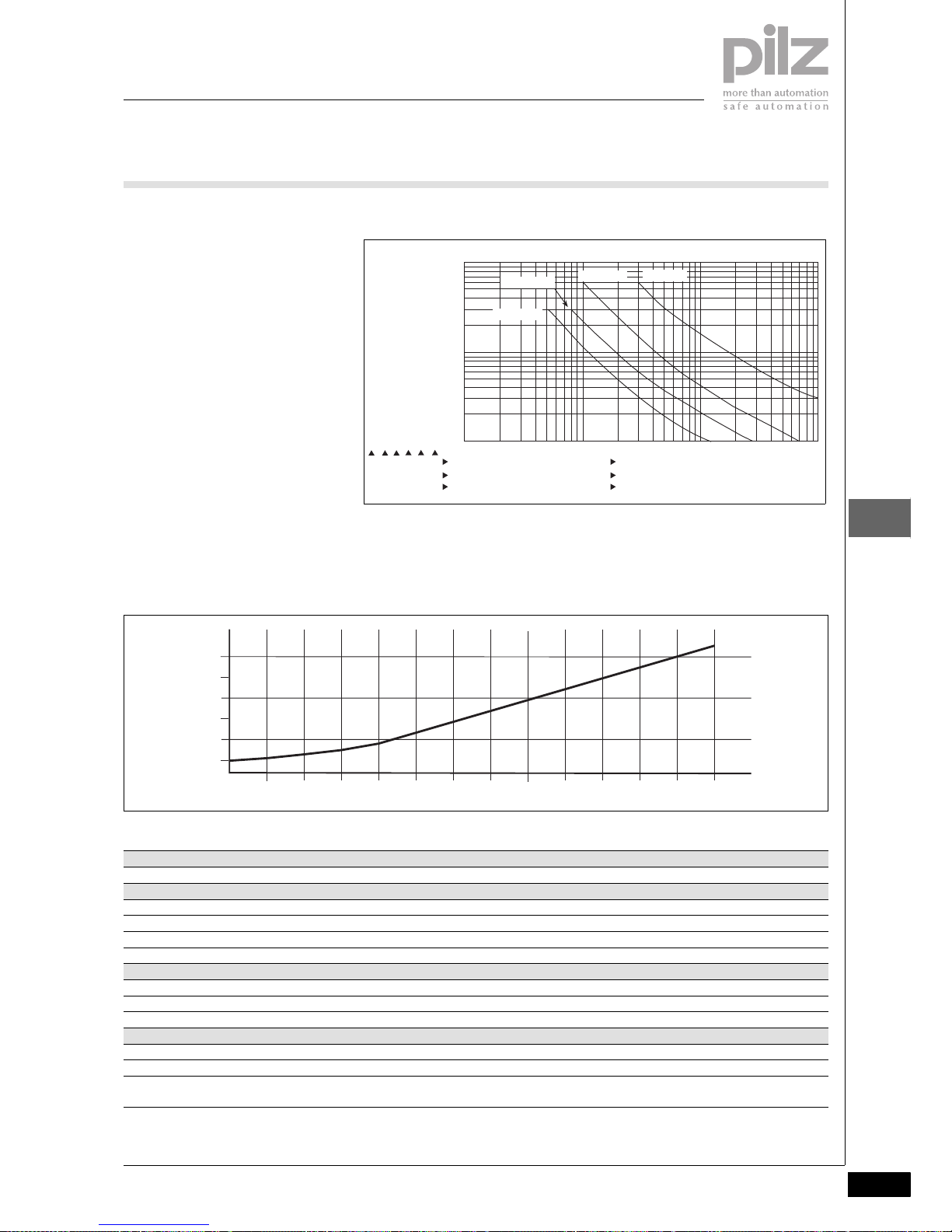
Products
Pilz GmbH & Co. KG, Sichere Automation, Felix-Wankel-Straße 2, 73760 Ostfildern, Germany
Telephone: +49 711 3409-0, Telefax: +49 711 3409-133, E-Mail: pilz.gmbh@pilz.de
Base units
PNOZ m2p
NSG-D-2-360-2007-09
2.2-35
2.2
Notice
This data sheet is only intended for use
during configuration. For installation
and operation, please refer to the operating instructions supplied with the
unit.
Service life graph
Maximum capacitive load C (μF)
with load current I (mA) at the semiconductor outputs
10
1
10 100 1000 10000
0.1
DC1: 24 V
AC1: 230 V
DC13: 24 V
AC15: 230 V
D Nennbetriebstrom (A)
GB Nominal operating current (A)
F Courant coupé (A)
E Corriente nominal de servicio (A)
I Corrente di esercizio nominale (A)
NL Nominale bedrijfsstroom (A)
D Schaltspielzahl x 10
3
GB Cycles x 10
3
F Nombre de manuvres x 10
3
E Número de ciclos x 10
3
I Numero dei cicli di commutazione x 10
3
NL Aantal schakelingen x 10
3
2
4
0
0 10 50 100 200 400 600 800
1000
1200 I (mA)
6
1400 1600 1800 2000
C (µF)
Technical details
Electrical data
Supply voltage (UB) 24 VDC
Voltage tolerance -15% ... 10%
Power consumption at U
B
without load Max. 8.0 W + 2.5 W per expansion module
Residual ripple U
B
+/- 5 %
Times
Switch-on delay 5 s (after UB is applied)
Simultaneity channel 1/2/3 3 s, two-hand control relay: 0.5 s
Supply interruption before de-energisation Min. 20 ms
Inputs
Quantity 20
Voltage and current 24 VDC/8 mA
Galvanic isolation
Cascading input
No
500 VAC
Page 80

Products
Base units
PNOZ m2p
NSG-D-2-360-2007-09Pilz GmbH & Co. KG, Sichere Automation, Felix-Wankel-Straße 2, 73760 Ostfildern, Germany
Telephone: +49 711 3409-0, Telefax: +49 711 3409-133, E-Mail: pilz.gmbh@pilz.de
2.2-36
2.2
Signal level at “0” -3 ... +5 VDC
Signal level at “1” 15 ... 30 VDC
Input delay 0.6 ... 4 ms
Status indicator LED
Test pulse outputs
Quantity 4
Voltage and current 24 VDC / 0.5 A
Off time during self test < 5 ms
Galvanic isolation No
Short circuit protection Yes
Status indicator LED
Semiconductor outputs
Quantity
For EN 954-1, 12/96, Cat. 4
For EN 954-1, 12/96, Cat. 3
2
4
Switching capability 24 VDC / max. 2 A / max. 48 W
Max. capacitive load See diagram
External supply voltage (U
B
) 24 VDC
Voltage tolerance -15% - 10%
Off time during self test < 300 μs
Galvanic isolation Yes
Short circuit protection Yes
Switch-off delay < 30 ms
Residual current at "0" < 0.5 mA
Signal level at “1” U
B
- 0.5 VDC at 2 A
Status indicator LED
Relay outputs
Quantity
For EN 954-1, 12/96, Cat. 4
For EN 954-1, 12/96, Cat. 2
1
2
Utilisation category in accordance with
EN 60947-4-1, 02/01
EN 60947-5-1, 11/97
AC1: 240 V / 6 A / 1440 VA
DC1: 24 V / 6 A / 144 W
AC15: 230 V / 3 A / 690 VA
DC13: 24 V / 3 A / 72 W
Contact fuse protection in accordance with EN 60947-5-1, 08/00
Blow-out fuse
Circuit breaker 24 VDC
6 A quick or slow
6 A (characteristic B + C)
Switch-off delay 50 ms
Status indicator LED
Auxiliary outputs
Quantity 1
Voltage and current 24 VDC / max. 0.5 A / max. 12 W
External supply voltage (U
B
) 24 VDC
Voltage tolerance -15% ... +10%
Galvanic isolation Yes
Short circuit protection Yes
Residual current at "0" < 0.5 mA
Signal level at “1” U
B
- 0.5 VDC at 0.5 A
Status indicator LED
Cascading output as auxiliary output
Quantity 1
Voltage and current 24 VDC / max. 0.2 A / max. 4.8 W
Galvanic isolation No
Short circuit protection Yes
Residual current at "0" < 0.5 mA
Inputs
Page 81

Products
Pilz GmbH & Co. KG, Sichere Automation, Felix-Wankel-Straße 2, 73760 Ostfildern, Germany
Telephone: +49 711 3409-0, Telefax: +49 711 3409-133, E-Mail: pilz.gmbh@pilz.de
Base units
PNOZ m2p
NSG-D-2-360-2007-09
2.2-37
2.2
Environmental data
Airgap creepage between
relay contacts
Relay contacts and other safe circuits
DIN VDE 0110-1, 04/97
3 mm
5.5 mm
Vibration in accordance with EN 60068-2-6, 04/95
Frequency:
Amplitude:
10 ... 55 Hz
0.35 mm
Climatic suitability DIN IEC 60068-2-3, 12/86
EMC EN 60947-5-1, 01/00
Ambient temperature 0 ... +55 °C
Storage temperature -25 ... +70 °C
Mechanical data
Protection type
Mounting (e.g. cabinet)
Housing
Terminals
IP54
IP20
IP20
DIN rail
Top hat rail
Recess width
35 x 7.5 EN 50022
27 mm
Maximum cable runs
Per input
Sum of individual cable runs at the test pulse output
1 km
40 km
Cross section of external conductors
Rigid single-core, flexible multi-core or multi-core
With crimp connector
Power supply (X7), inputs (X5, X6), semiconductor outputs (X2), test
pulse outputs (X1)
auxiliary output (X2), cascading output
Relay outputs (X3)
Flexible multi-core with plastic sleeve
Relay outputs (X3)
0.5 ... 1.5 mm
2
0.5 ... 2.5 mm
2
0.5 ... 1.5 mm
2
Torque setting for connection terminals (screws)
Power supply (X7), inputs (X5, X6), semiconductor outputs (X2), test
pulse outputs (X1),
auxiliary output (X2), cascading output
Relay outputs (X3)
0.2 ... 0.25 Nm
0.4 ... 0.5 Nm
Housing material
Housing
Front
PPO UL 94 V0
ABS UL 94 V0
Dimensions (H x W x D) 94 x 135 x 121 mm
Weight with connector 530 g
Order reference
Type Features Order no.
PNOZ m2p Base unit 773 120
Page 82

Products
Expansion modules
Pilz GmbH & Co. KG, Sichere Automation, Felix-Wankel-Straße 2, 73760 Ostfildern, Germany
Telephone: +49 711 3409-0, Telefax: +49 711 3409-133, E-Mail: pilz.gmbh@pilz.de
2.3-0
2.3
ProductsExpansion mod ules2.3
Page 83

Products
Pilz GmbH & Co. KG, Sichere Automation, Felix-Wankel-Straße 2, 73760 Ostfildern, Germany
Telephone: +49 711 3409-0, Telefax: +49 711 3409-133, E-Mail: pilz.gmbh@pilz.de
Expansion modules
2008-03
2.3-1
2.3
Contents Page
Expansion modules
PNOZ ma1p 2.3-2
PNOZ mi1p 2.3-8
PNOZ mi1p coated version 2.3-13
PNOZ mi2p 2.3-18
PNOZ mo1p 2.3-22
PNOZ mo1p coated version 2.3-28
PNOZ mo2p 2.3-34
PNOZ mo2p coated version 2.3-40
PNOZ mo3p 2.3-46
PNOZ mo4p 2.3-52
PNOZ mo4p coated version 2.3-58
PNOZ mc0p 2.3-64
PNOZ mc1p 2.3-68
PNOZ mc1p coated version 2.3-72
PNOZ mc3p 2.3-77
PNOZ mc4p 2.3-81
PNOZ mc4p coated version 2.3-85
PNOZ mc5p 2.3-89
PNOZ mc5.1p 2.3-93
PNOZ mc6p 2.3-97
PNOZ mc6p coated version 2.3-101
PNOZ mc7p 2.3-105
PNOZ mc8p 2.3-109
PNOZ mc9p 2.3-113
PNOZ ml1p 2.3-117
PNOZ ms1p 2.3-124
PNOZ ms2p 2.3-131
Page 84

Products
Expansion modules
PNOZ ma1p
NSG-D-2-407-2008-03Pilz GmbH & Co. KG, Sichere Automation, Felix-Wankel-Straße 2, 73760 Ostfildern, Germany
Telephone: +49 711 3409-0, Telefax: +49 711 3409-133, E-Mail: pilz.gmbh@pilz.de
2.3-2
2.3
PNOZ ma1p2.3NSG-D-2-407-2008-03ProductsExpansion modulesPNOZ ma1pPNOZ ma1p
Expansion module for connection to a
base unit from the PNOZmulti modular
safety system
Approvals
Unit features
` 2 safe analogue inputs for current
or voltage measurement (configurable)
` Voltage range:
-10,24 ... +10.2375 V
` Current range: 0 ... 25.59 mA
` Resolution
– Voltage measurement: 13 Bit
(signed 12 Bit)
– Current measurement: 12 Bit
` Range monitoring (4 range limits
can be configured)
` Threshold value monitoring (8
threshold values can be configured)
` Max. 4 PNOZ ma1p units can be
connected to the base unit
` LED indicators for
– Operating status
– Status of the input signals (Ch0,
Ch1)
– Errors
Unit description
The expansion module is an analogue
input module. It provides 2 safe analogue inputs for current or voltage
measurement. For current measurement, both inputs can be used independently. For voltage measurement,
both inputs must always be wired. The
analogue inputs are suitable for connecting transducers or input devices
with standardised 10 V voltage signals
or 20 mA current signals. The analogue inputs are designed as differential inputs. Each analogue input has a
signal range of –10 VDC to +10 VDC or
0 mA to 25 mA.
The expansion module may only be
connected to a base unit from the
PNOZmulti modular safety system.
The PNOZmulti modular safety system
is used for the safety-related interruption of safety circuits and is designed
for use on:
` Emergency stop equipment
` Safety circuits in accordance with
VDE 0113 Part 1 and EN 60204-1
System requirements
` PNOZmulti Configurator: from Ver-
sion 5.3.0
` Base unit PNOZ m1p: from Version
5.6
` Base unit PNOZ m2p: from
Version 2.6
Please contact Pilz if you have an older
version.
Safety features
The PNOZ ma1p expansion module
fulfils the following safety requirements:
The circuit is redundant with built-in
self-monitoring.
` The safety function remains effec-
tive in the case of a component fail-
ure.
The analogue input module can be
used for current measurement for
applications up to SIL3.
For applications in accordance with
SIL2 or SIL3, input devices must be
connected that are certified for SIL2 in
accordance with IEC 61508. The output signal of the input device must be
monitored, i.e. the actual and set value
must be compared. If there is any deviation there must be a reaction that
the PNOZmulti will recognise and to
which it will react.
` SIL2 applications:
SIL2 applications are only possible
for current measurement. If the an-
alogue input module is to be used
for current measurement on SIL2
applications, both inputs can be
used independently for current
measurement.
` SIL 3 applications:
If the analogue input module is to
be used for SIL3 applications, both
inputs must be configured and then
combined to form a SIL3 input. To
do this, connect a suitable input de-
vice to each input. The analogue in-
put module will then check the
feasibility of the input signals, i.e.
the values measured from both in-
put signals are compared.
PNOZ ma1p
Page 85

Products
Pilz GmbH & Co. KG, Sichere Automation, Felix-Wankel-Straße 2, 73760 Ostfildern, Germany
Telephone: +49 711 3409-0, Telefax: +49 711 3409-133, E-Mail: pilz.gmbh@pilz.de
Expansion modules
PNOZ ma1p
NSG-D-2-407-2008-03
2.3-3
2.3
Block diagram
Function description
The analogue input module monitors
analogue input signals. It can measure
both current and voltage.
The input signals are collected and
read in at each input through two
channels and are converted into digital
signals. The resolution is 13 Bit for
voltage measurement, 12 Bit for current measurement.
Monitoring types
In the PNOZmulti Configurator you can
define limit values, which are to be
monitored:
` Range monitoring
With range monitoring you can define the permitted value range. You
can define up to 4 range limits (e.g.
< 3 mA monitored for input device
error). Depending on the selected
condition ("greater than" or "less
than"), the ENBL output bit and output bits 1 - 8 for threshold value
monitoring are set to "0" if the recorded value exceeds or drops below a range limit. An entry is added
to the error stack.
Exception: If "automatic reset" type
has been selected, no entry will be
added to the error stack.
` Threshold value monitoring
You can define up to 8 switching
thresholds, which can be used to
monitor certain process variables
(e.g. different temperature values).
The thresholds can be configured
with or without scaling. 2 threshold
values are configured per threshold. One threshold value defines
when the relevant output bit (1 ... 8)
is set to "1". The second threshold
value defines when the output bit is
reset to "0". No entry is added to
the error stack.
Evaluate analogue values
The exact analogue values are made
available to the base unit to forward to
a fieldbus. This value is transmitted
through a single channel and is not
safety-related. It can be used for diagnostic purposes.
The online help on the PNOZmulti
Configurator contains descriptions of
the operating modes and all the functions of the PNOZmulti safety system.
24V 24V
=
Power
=
0V 0V
Interface
to previous
module
Interface
to next
module
0V24V
Input
I0+ I0-
U0+ U0-
I1+ I1-
U1+ U1-
=
=
24V 24V
24V
0V 0V
0V
ADC
Input
Page 86
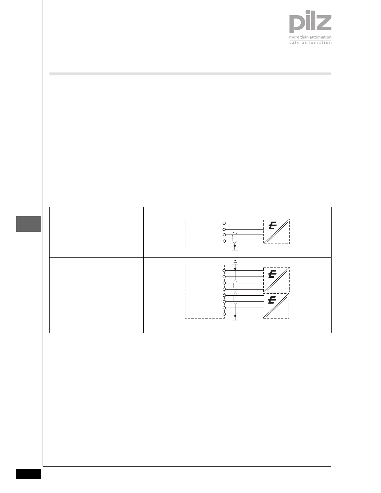
Products
Expansion modules
PNOZ ma1p
NSG-D-2-407-2008-03Pilz GmbH & Co. KG, Sichere Automation, Felix-Wankel-Straße 2, 73760 Ostfildern, Germany
Telephone: +49 711 3409-0, Telefax: +49 711 3409-133, E-Mail: pilz.gmbh@pilz.de
2.3-4
2.3
Wiring
Please note the following when preparing for commissioning:
` The wiring is defined in the circuit
diagram of the PNOZmulti Configurator.
` The power supply that feeds the ex-
pansion module and the input device must meet the regulations for
extra low voltages with safe separation (SELV, PELV).
` 6 connection terminals are available
for each of the supply connections
24 V and 0 V. This means that the
supply voltage can be looped
through several connections and
the input device can be supplied.
` Use shielded, twisted pair cable for
the connections on the input current circuits.
` Separate the supply voltage cable
from the analogue input current
lines.
` If the analogue input module is
used to measure current, the voltage inputs must be short-circuited.
` For transducers located outside the
control cabinet: Where the cable
enters the control cabinet, the cable
shield must be connected to the
earth potential over a wide surface
area and with low impedance (con-
nect in star).
` Use copper wiring that can with-
stand temperatures of 60/75 °C.
` The torque setting of the screws on
the connection terminals is speci-
fied in the "Technical details" sec-
tion.
Preparing for operation
` Connection to transducer
Please note:
` The transducers are SIL2 certified
` The voltage supply to the input de-
vice is optional
` With current measurement, the
voltage inputs U+ - U- must be
short-circuited.
Example for current measurement
SIL2 application
SIL3 application
I0+
PNOZ ma1p
I0-
24 V
0 V
I0+
PNOZ ma1p
I0I1-
I1-
24 V
0 V
24 V
0 V
Page 87

Products
Pilz GmbH & Co. KG, Sichere Automation, Felix-Wankel-Straße 2, 73760 Ostfildern, Germany
Telephone: +49 711 3409-0, Telefax: +49 711 3409-133, E-Mail: pilz.gmbh@pilz.de
Expansion modules
PNOZ ma1p
NSG-D-2-407-2008-03
2.3-5
2.3
Notice
This data sheet is only intended for use
during configuration. For installation
and operation, please refer to the operating instructions supplied with the
unit.
Terminal configuration
Installation
` The safety system should be in-
stalled in a control cabinet with a
protection type of at least IP54. Fit
the safety system to a horizontal
DIN rail. The venting slots must face
upward and downward. Other
mounting positions could damage
the safety system.
` Use the notches on the back of the
unit to attach it to a DIN rail. Connect the safety system to the DIN
rail in an upright position, so that
the earthing springs on the safety
system are pressed on to the DIN
rail.
` To comply with EMC requirements,
the DIN rail must have a low impedance connection to the control cabinet housing.
Please note for installation:
CAUTION!
Electrostatic discharge can damage
components on the expansion module
PNOZ ma1p. Ensure against discharge before touching the
PNOZ ma1p, e.g. by touching an
earthed, conductive surface or by
wearing an earthed armband.
Dimensions
94 (3.70")
45
(1.77")
121 (4.76")
Page 88

Products
Expansion modules
PNOZ ma1p
NSG-D-2-407-2008-03Pilz GmbH & Co. KG, Sichere Automation, Felix-Wankel-Straße 2, 73760 Ostfildern, Germany
Telephone: +49 711 3409-0, Telefax: +49 711 3409-133, E-Mail: pilz.gmbh@pilz.de
2.3-6
2.3
Technical details
Electrical data
Supply voltage
Supply voltage U
B
DC 24 V
Voltage tolerance -15 %/+20 %
Power consumption at U
B
DC 2 W
Residual ripple DC 5 %
Timers
Switch-on delay 5 s
Max. reaction time when the input signal changes 100 ms
Supply interruption before de-energisation 20 ms
Inputs
Number of analogue inputs 2
Type of analogue inputs Voltage, Current
Max.measurement error at 25 °C 0,5 %
Temperature coefficient* 0.0025 %/K
Max. measurement error at full temperature range*0,5 %
Greatest transient deviation during el. interference test*1.0 %
Max. measurement error in the cas of a potential module error 1,5 %
Max. voltage between inputs I0 and I1 with current or voltage
measurement
+/- 15 V
Analogue input filter First order
Cutoff frequency 80 Hz
Filter time constant 2.0 ms
Galvanic isolation between the inputs no
Current measurement
Signal range 0.00 - 25.59 mA
Value range 0 - 4095 d
Resolution 12 Bit
Value of least significant bit (LSB) 6.25 µA
Input impedance 100 Ohm
Max. continuous current 50 mA
Voltage measurement
Signal range -10.2400 - 10.2375 V
Value range -4096 - 4095 d
Resolution 13 Bit
Value of least significant bit (LSB) 5 mV
Min. input impedance 290 kOhm
Environmental data
EMC EN 61000-4-2, EN 61000-4-3, EN 61000-4-4, EN 61000-4-5, EN
61000-4-6, EN 61000-6-2, EN 61000-6-4
Vibration to EN 60068-2-6
Frequency 10 - 55 Hz
Amplitude 0.35 mm
Climatic suitability EN 60068-2-14, EN 60068-2-1, EN 60068-2-2, EN 60068-2-30,
EN 60068-2-78
Airgap creepage in accordance with EN 60664-1
Ambient temperature 0 - 60 °C
Storage temperature -25 - 70 °C
Protection type
Mounting (e.g. cabinet) IP54
Housing IP20
Terminals IP20
Page 89

Products
Pilz GmbH & Co. KG, Sichere Automation, Felix-Wankel-Straße 2, 73760 Ostfildern, Germany
Telephone: +49 711 3409-0, Telefax: +49 711 3409-133, E-Mail: pilz.gmbh@pilz.de
Expansion modules
PNOZ ma1p
NSG-D-2-407-2008-03
2.3-7
2.3
*in relation to the measuring range
The standards current on 2007-08 apply.
Mechanical data
DIN rail
Top hat rail 35 x 7.5 EN 50022
Recess width 27 mm
Housing material
Housing PPO UL 94 V0
Front ABS UL 94 V0
Cross section of external conductors with screw terminals
Rigid single-core, flexible multi-core or multi-core with crimp connector 0.5 … 1.5 mm2, 22-14 AWG
Torque setting with screw terminals 0.25 Nm
Stripping length 9 mm
Dimensions
Height 94.0 mm
Width 45.0 mm
Depth 121.0 mm
Weight 200 g
Order reference
Type Order no.
PNOZ ma1p Expansion module 2 analogue inputs 773 812
Page 90

Products
Expansion modules
PNOZ mi1p
NSG-D-2-369-2007-09Pilz GmbH & Co. KG, Sichere Automation, Felix-Wankel-Straße 2, 73760 Ostfildern, Germany
Telephone: +49 711 3409-0, Telefax: +49 711 3409-133, E-Mail: pilz.gmbh@pilz.de
2.3-8
2.3
PNOZ mi1p2.3NSG-D-2-369-2007-09ProductsExpansion m odulesPNOZ mi1 pPNOZ mi1p
Expansion module for connection to a
base unit from the PNOZmulti modular
safety system
Approvals
Unit features
` 8 inputs for connecting:
– E-STOP pushbutton
– Two-hand button
– Safety gate limit switch
– Reset button
– Light barrier
– Scanner
– Enable switch
– PSEN
– Operating mode selector switch
` Can be configured in the PNOZmul-
ti Configurator
` LED indicator for:
– Status of the PNOZmulti safety
system
` Max. 8 PNOZ mi1p units can be
connected to the base unit
` Test pulse outputs used to detect
shorts across the inputs
` Plug-in connection terminals (either
cage clamp terminal or screw terminal)
Unit description
The expansion module may only be
connected to a base unit from the
PNOZmulti modular safety system.
The PNOZmulti modular safety system
is used for the safety-related interruption of safety circuits and is designed
for use on:
` Emergency stop equipment
` Safety circuits in accordance with
VDE 0113 Part 1 and EN 60204-1
Safety features
The relay conforms to the following
safety criteria:
` The circuit is redundant with built-in
self-monitoring.
` The safety function remains effec-
tive in the case of a component fail-
ure.
Block diagram
PNOZ mi1p
I0 I1
Interface
to previous
module
Interface
to next
module
I2 I3 I4 I5 I6 I7
Input
Page 91

Products
Pilz GmbH & Co. KG, Sichere Automation, Felix-Wankel-Straße 2, 73760 Ostfildern, Germany
Telephone: +49 711 3409-0, Telefax: +49 711 3409-133, E-Mail: pilz.gmbh@pilz.de
Expansion modules
PNOZ mi1p
NSG-D-2-369-2007-09
2.3-9
2.3
Function description
The expansion module provides additional inputs.
The function of the inputs on the safety
system depends on the safety circuit
created using the PNOZmulti Configurator. A chip card is used to download
the safety circuit to the base unit. The
base unit has 2 microcontrollers that
monitor each other. They evaluate the
input circuits on the base unit and expansion modules and switch the outputs on the base unit and expansion
modules accordingly.
The online help on the PNOZmulti
Configurator contains descriptions of
the operating modes and all the functions of the PNOZmulti safety system,
plus connection examples.
Wiring
The wiring is defined in the circuit diagram of the PNOZmulti Configurator.
Please note:
` Information given in the "Technical
details" must be followed.
` Connection terminals I0 ... I7 are in-
puts
` Power for the safety system and in-
put circuits must always be provided from a single power supply. The
power supply must meet the regulations for extra low voltages with
safe separation.
` The test pulse outputs on the base
unit must be used to detect shorts
across contacts.
` Use copper wire that can withstand
75 °C.
Page 92

Products
Expansion modules
PNOZ mi1p
NSG-D-2-369-2007-09Pilz GmbH & Co. KG, Sichere Automation, Felix-Wankel-Straße 2, 73760 Ostfildern, Germany
Telephone: +49 711 3409-0, Telefax: +49 711 3409-133, E-Mail: pilz.gmbh@pilz.de
2.3-10
2.3
Preparing for operation
` Input circuit
` Key
Input circuit Single-channel Dual-channel
Example:
E-STOP
without detection of shorts across contacts
Example:
E-STOP
with detection of shorts across contacts
S1
I0
L+
S1
I1
I0
L+
L+
I0
T0
S1
S1
T1
I1
T0
I0
S1 E-STOP pushbutton
Page 93

Products
Pilz GmbH & Co. KG, Sichere Automation, Felix-Wankel-Straße 2, 73760 Ostfildern, Germany
Telephone: +49 711 3409-0, Telefax: +49 711 3409-133, E-Mail: pilz.gmbh@pilz.de
Expansion modules
PNOZ mi1p
NSG-D-2-369-2007-09
2.3-11
2.3
Terminal configuration
Installation
` The safety system should be in-
stalled in a control cabinet with a
protection type of at least IP54. Fit
the safety system to a horizontal
DIN rail. The venting slots must face
upward and downward. Other
mounting positions could damage
the safety system.
` Use the notches on the back of the
unit to attach it to a DIN rail. Connect the safety system to the DIN
rail in an upright position, so that
the earthing springs on the safety
system are pressed on to the DIN
rail.
` To comply with EMC requirements,
the DIN rail must have a low impedance connection to the control cabinet housing.
Dimensions
773400
94 (3.70")
22,5
(0.88")
121 (4.76")
Page 94

Products
Expansion modules
PNOZ mi1p
NSG-D-2-369-2007-09Pilz GmbH & Co. KG, Sichere Automation, Felix-Wankel-Straße 2, 73760 Ostfildern, Germany
Telephone: +49 711 3409-0, Telefax: +49 711 3409-133, E-Mail: pilz.gmbh@pilz.de
2.3-12
2.3
Notice This data sheet is only intended for use
during configuration. For installation
and operation, please refer to the op-
erating instructions supplied with the
unit.
Technical details
Electrical data
Supply voltage (UB) 24 VDC
Power consumption at U
B
without load Max. 8.0 W + 2.5 W per expansion module
Times
Switch-on delay 5 s (after UB is applied)
Simultaneity channel 1/2/3 3 s, two-hand control relay: 0.5 s
Supply interruption before de-energisation Min. 20 ms
Inputs
Quantity 8
Voltage and current 24 VDC/8 mA
Galvanic isolation No
Signal level at “0” -3 ... +5 VDC
Signal level at “1” 15 ... 30 VDC
Input delay 0.6 ... 4 ms
Status indicator LED
Environmental data
Airgap creepage DIN VDE 0110-1, 04/97
Vibration in accordance with EN 60068-2-6, 04/95
Frequency:
Amplitude:
10 ... 55 Hz
0.35 mm
Climatic suitability EN 60068-2-78, 10/01
EMC EN 60947-5-1, 11/97
Ambient temperature 0 ... +55 °C
Storage temperature -25 ... +70 °C
Mechanical data
Protection type
Mounting (e.g. cabinet)
Housing
Terminals
IP54
IP20
IP20
DIN rail
Top hat rail
Recess width
35 x 7.5 EN 50022
27 mm
Cross section of external conductors
Rigid single-core, flexible multi-core or multi-core
With crimp connector 0.5 ... 1.5 mm
2
Torque setting for connection terminals (screws) 0.2 ... 0.25 Nm
Housing material
Housing
Front
PPO UL 94 V0
ABS UL 94 V0
Dimensions (H x W x D) 94 x 22.5 x 121 mm
Weight with connector 130 g
Order reference
Type Features Order no.
PNOZ mi1p Expansion module 8 inputs 773 400
Page 95

Products
Pilz GmbH & Co. KG, Sichere Automation, Felix-Wankel-Straße 2, 73760 Ostfildern, Germany
Telephone: +49 711 3409-0, Telefax: +49 711 3409-133, E-Mail: pilz.gmbh@pilz.de
Expansion modules
PNOZ mi1p coated version
NSG-D-2-370-2007-09
2.3-13
2.3
PNOZ mi1p coated version2.3NSG-D-2-370-2007-09ProductsExpansion m odulesPNOZ mi1p coated versionPNOZ mi1p coated version
Expansion module for connection to a
base unit from the PNOZmulti modular
safety system
Approvals
Unit features
` 8 inputs for connecting:
– E-STOP pushbutton
– Two-hand button
– Safety gate limit switch
– Reset button
– Light beam devices
– Scanner
– Enable switch
– PSEN
– Operating mode selector switch
` Can be configured in the PNOZmul-
ti Configurator
` LED for:
– Status of the PNOZmulti safety
system
` Max. 8 PNOZ mi1p units can be
connected to the base unit
` Test pulse outputs used to detect
shorts across the inputs
` Plug-in connection terminals (either
cage clamp terminal or screw terminal)
Unit description
The expansion module may only be
connected to a base unit from the
PNOZmulti modular safety system.
The PNOZmulti modular safety system
is used for the safety-related interrup-
tion of safety circuits and is designed
for use on:
` Emergency stop equipment
` Safety circuits in accordance with
VDE 0113 Part 1 and EN 60204-1
Safety features
The relay conforms to the following
safety criteria:
` The circuit is redundant with built-in
self-monitoring.
` The safety function remains effec-
tive in the case of a component fail-
ure.
Block diagram
PNOZ mi1p coated
version
I0 I1
Interface
to previous
module
Interface
to next
module
I2 I3 I4 I5 I6 I7
Input
Page 96

Products
Expansion modules
PNOZ mi1p coated version
NSG-D-2-370-2007-09Pilz GmbH & Co. KG, Sichere Automation, Felix-Wankel-Straße 2, 73760 Ostfildern, Germany
Telephone: +49 711 3409-0, Telefax: +49 711 3409-133, E-Mail: pilz.gmbh@pilz.de
2.3-14
2.3
Function description
The expansion module provides additional inputs.
The function of the inputs on the safety
system depends on the safety circuit
created using the PNOZmulti Configurator. A chip card is used to download
the safety circuit to the base unit. The
base unit has 2 microcontrollers that
monitor each other. They evaluate the
input circuits on the base unit and expansion modules and switch the outputs on the base unit and expansion
modules accordingly.
The online help on the PNOZmulti
Configurator contains descriptions of
the operating modes and all the functions of the PNOZmulti safety system,
plus connection examples.
Wiring
The wiring is defined in the circuit diagram of the PNOZmulti Configurator.
Please note:
` Information given in the "Technical
details" must be followed.
` Connection terminals I0 ... I7 are in-
puts
` Power for the safety system and in-
put circuits must always be provided from a single power supply. The
power supply must meet the regulations for extra low voltages with
safe separation.
` The test pulse outputs on the base
unit must be used to detect shorts
across contacts.
` Use copper wire that can withstand
75 °C.
Page 97

Products
Pilz GmbH & Co. KG, Sichere Automation, Felix-Wankel-Straße 2, 73760 Ostfildern, Germany
Telephone: +49 711 3409-0, Telefax: +49 711 3409-133, E-Mail: pilz.gmbh@pilz.de
Expansion modules
PNOZ mi1p coated version
NSG-D-2-370-2007-09
2.3-15
2.3
Preparing for operation
` Input circuit
` Key
Input circuit Single-channel Dual-channel
Example:
E-STOP
without detection of shorts across contacts
Example:
E-STOP
with detection of shorts across contacts
S1
I0
L+
S1
I1
I0
L+
L+
I0
T0
S1
S1
T1
I1
T0
I0
S1 E-STOP pushbutton
Page 98

Products
Expansion modules
PNOZ mi1p coated version
NSG-D-2-370-2007-09Pilz GmbH & Co. KG, Sichere Automation, Felix-Wankel-Straße 2, 73760 Ostfildern, Germany
Telephone: +49 711 3409-0, Telefax: +49 711 3409-133, E-Mail: pilz.gmbh@pilz.de
2.3-16
2.3
Terminal configuration
Installation
` The safety system should be in-
stalled in a control cabinet with a
protection type of at least IP54. Fit
the safety system to a horizontal
DIN rail. The venting slots must face
upward and downward. Other
mounting positions could damage
the safety system.
` Use the notches on the back of the
unit to attach it to a DIN rail. Connect the safety system to the DIN
rail in an upright position, so that
the earthing springs on the safety
system are pressed on to the DIN
rail.
` To comply with EMC requirements,
the DIN rail must have a low impedance connection to the control cabinet housing.
Dimensions
773400
94 (3.70")
22,5
(0.88")
121 (4.76")
Page 99

Products
Pilz GmbH & Co. KG, Sichere Automation, Felix-Wankel-Straße 2, 73760 Ostfildern, Germany
Telephone: +49 711 3409-0, Telefax: +49 711 3409-133, E-Mail: pilz.gmbh@pilz.de
Expansion modules
PNOZ mi1p coated version
NSG-D-2-370-2007-09
2.3-17
2.3
Notice This data sheet is only intended for use
during configuration. For installation
and operation, please refer to the op-
erating instructions supplied with the
unit.
Technical details
Electrical data
Supply voltage (UB) 24 VDC
Power consumption at U
B
without load Max. 8.0 W + 2.5 W per expansion module
Times
Switch-on delay 5 s (after UB is applied)
Simultaneity channel 1/2/3 3 s, two-hand control relay: 0.5 s
Supply interruption before de-energisation Min. 20 ms
Inputs
Quantity 8
Voltage and current 24 VDC/8 mA
Galvanic isolation No
Signal level at “0” -3 ... +5 VDC
Signal level at “1” 15 ... 30 VDC
Input delay 0.6 ... 4 ms
Status indicator LED
Environmental data
Airgap creepage DIN VDE 0110-1, 04/97
Vibration in accordance with EN 60068-2-6, 04/95
Frequency:
Amplitude:
10 ... 55 Hz
0.35 mm
Climatic suitability EN 60068-2-78, 10/01
EMC EN 60947-5-1, 11/97
Ambient temperature 0 ... +50 °C
Storage temperature -25 ... +70 °C
Mechanical data
Protection type
Mounting (e.g. cabinet)
Housing
Terminals
IP54
IP20
IP20
DIN rail
Top hat rail
Recess width
35 x 7.5 EN 50022
27 mm
Cross section of external conductors
Rigid single-core, flexible multi-core or multi-core
With crimp connector 0.5 ... 1.5 mm
2
Torque setting for connection terminals (screws) 0.2 ... 0.25 Nm
Housing material
Housing
Front
PPO UL 94 V0
ABS UL 94 V0
Dimensions (H x W x D) 94 x 22.5 x 121 mm
Weight with connector 130 g
Order reference
Type Features Order no.
PNOZ mi1p
coated version
Expansion module 8 inputs 773 405
Page 100

Products
Expansion modules
PNOZ mi2p
NSG-D-2-385-2006-02Pilz GmbH & Co. KG, Sichere Automation, Felix-Wankel-Straße 2, 73760 Ostfildern, Germany
Telephone: +49 711 3409-0, Telefax: +49 711 3409-133, E-Mail: pilz.gmbh@pilz.de
2.3-18
2.3
PNOZ mi2p2.3NSG-D-2-385-2006-02ProductsExpansion m odulesPNOZ mi2 pPNOZ mi2p
Expansion module for connection to a
base unit from the PNOZmulti modular
safety system
Unit features
` 8 inputs for standard functions
` Can be configured in the PNOZmul-
ti Configurator
` LED indicator for:
– Status of the PNOZmulti safety
system
` Max. 8 PNOZ mi1p units can be
connected to the base unit
` Plug-in connection terminals (either
cage clamp terminal or screw terminal)
Unit description
The PNOZmulti modular safety system
is used for the safety-related interruption of safety circuits and is designed
for use on:
` Emergency stop equipment
` Safety circuits in accordance with
VDE 0113 Part 1 and EN 60204-1
The expansion module may only be
connected to a base unit from the
PNOZmulti modular safety system.
The expansion module may not be
used for safety-related functions.
Block diagram
I0 I1
Interface
to previous
module
Interface
to next
module
I2 I3 I4 I5 I6 I7
Input
 Loading...