

Page 1
WORKSHOP MANUAL
618153
MSS X9 Evolution 250
Page 2

WORKSHOP
MANUAL
MSS X9 Evolution 250
The descriptions and illustrations given in this publication are not binding. While the basic specifications
as described and illustrated in this booklet remain unchanged, PIAGGIO-GILERA reserves the right, at
any time and without being required to update this publication beforehand, to make any changes to
components, parts or accessories, which it considers necessary to improve the product or which are
required for manufacturing or construction reasons.
Not all versions/models shown in this publication are available in all countries. The availability of single
models should be checked at the official Piaggio sales network.
"© Copyright 2007 - PIAGGIO & C. S.p.A. Pontedera. All rights reserved. Reproduction of this publication
in whole or in part is prohibited."
PIAGGIO & C. S.p.A. - After-Sales
V.le Rinaldo Piaggio, 23 - 56025 PONTEDERA (Pi)
Page 3
WORKSHOP MANUAL
MSS X9 Evolution 250
This workshop manual has been drawn up by Piaggio & C. Spa to be used by the workshops of PiaggioGilera dealers. This manual is addressed to Piaggio service mechanics who are supposed to have a
basic knowledge of mechanics principles and of vehicle fixing techniques and procedures. Any important
changes made to the vehicles or to specific fixing operations will be promptly reported by updates to this
manual. Nevertheless, no fixing work can be satisfactory if the necessary equipment and tools are
unavailable. It is therefore advisable to read the sections of this manual relating to specific tools, along
with the specific tool catalogue.
N.B. Provides key information to make the procedure easier to understand and carry out.
CAUTION Refers to specific procedures to carry out for preventing damages to the vehicle.
WARNING Refers to specific procedures to carry out to prevent injuries to the repairer.
Personal safety Failure to completely observe these instructions will result in serious risk of personal
injury.
Safeguarding the environment Sections marked with this symbol indicate the correct use of the vehicle
to prevent damaging the environment.
Vehicle intactness The incomplete or non-observance of these regulations leads to the risk of serious
damage to the vehicle and sometimes even the invalidity of the guarantee.
Page 4

Page 5

INDEX OF TOPICS
CHARACTERISTICS CHAR
TOOLING TOOL
MAINTENANCE MAIN
TROUBLESHOOTING TROUBL
ELECTRICAL SYSTEM ELE SYS
ENGINE FROM VEHICLE ENG VE
ENGINE ENG
SUSPENSIONS SUSP
BRAKING SYSTEM BRAK SYS
COOLING SYSTEM COOL SYS
CHASSIS CHAS
PRE-DELIVERY PRE DE
TIME TIME
Page 6

INDEX OF TOPICS
CHARACTERISTICS CHAR
Page 7

MSS X9 Evolution 250 Characteristics
Rules
This section describes general safety rules for any maintenance operations performed on the vehicle.
Safety rules
- If work can only be done on the vehicle with the engine running, make sure that the premises are wellventilated, using special extractors if necessary; never let the engine run in an enclosed area. Exhaust
fumes are toxic.
- The battery electrolyte contains sulphuric acid. Protect your eyes, clothes and skin. Sulphuric acid is
highly corrosive; in the event of contact with your eyes or skin, rinse thoroughly with abundant water
and seek immediate medical attention.
- The battery produces hydrogen, a gas that can be highly explosive. Do not smoke and avoid sparks
or flames near the battery, especially when charging it.
- Fuel is highly flammable and it can be explosive given some conditions. Do not smoke in the working
area, and avoid open flames or sparks.
- Clean the brake pads in a well-ventilated area, directing the jet of compressed air in such a way that
you do not breathe in the dust produced by the wear of the friction material. Even though the latter
contains no asbestos, inhaling dust is harmful.
Maintenance rules
- Use original PIAGGIO spare parts and lubricants recommended by the Manufacturer. Non-original or
non-conforming spares may damage the vehicle.
- Use only the appropriate tools designed for this vehicle.
- Always use new gaskets, sealing rings and split pins upon refitting.
- After removal, clean the components using non-flammable or low flash-point solvents. Lubricate all
the work surfaces except the tapered couplings before refitting.
- After refitting, make sure that all the components have been installed correctly and work properly.
- For removal, overhaul and refit operations use only tools with metric measures. Metric bolts, nuts and
screws are not interchangeable with coupling members with English measurement. Using unsuitable
coupling members and tools may damage the scooter.
- When carrying out maintenance operations on the vehicle that involve the electrical system, make
sure the electric connections have been made properly, particularly the ground and battery connections.
CHAR - 7
Page 8
Characteristics MSS X9 Evolution 250
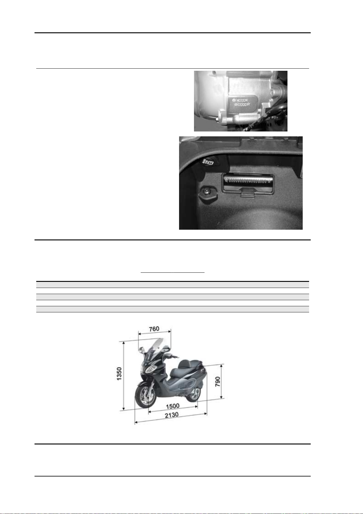
Vehicle identification
Chassis prefix: ZAPMXXXX > XXXXXX
Engine prefix: M23XM
Dimensions and mass
Specification
Empty weight 173 Kg
Wheelbase 1500 mm
Overall height 1450 mm
Saddle height 790 mm
Overall length 2130 mm
Overall width 910 mm
DIMENSIONS AND WEIGHT
Desc./Quantity
CHAR - 8
Page 9

MSS X9 Evolution 250 Characteristics
Engine
Characteristics Version 250
Type Single-cylinder, 4 stroke and 4 valves
Piaggio QUASAR with secondary air sys-
tem and catalytic converter.
Cooling system Liquid
Number of cylinders 1
Bore 72 mm
Stroke 60 mm
Piston displacement 244,29 cm3
Compression ratio 10,5 - 11,5 : 1
Timing system Single-head camshaft controlled by left
side chain, 3-arm rockers with threaded
register.
Valve clearance:
intake
exhaust
Walbro Carburettor WVFH
Kehin Carburettor CVK 30
Air filter Sponge, impregnated with mixture (50%
Start-up system electric starter
Lubrication with twin-screw pump (inside the crank-
Power supply Petrol (with minimum octane level 95,
0,10 mm
0,15 mm
Selenia Air Filter Oil and 50% lead-free
fuel).
case) controlled by chain and dual filter:
net and paper filter.
lead-free) with vacuum pump and
through carburettor.
Max speed xxx Km/h
Spark plug CHAMPION RG4HC
Transmission
TRANSMISSIONS
Specification
Transmission With automatic expandable pulley variator, V belt, automatic
clutch, gear reduction unit and transmission housing with
Desc./Quantity
forced-circulation air cooling.
CHAR - 9
Page 10
Characteristics MSS X9 Evolution 250
Gas control transmission fixing
Please take note that starting from the frame number ZAPM2300004502417, the gas control transmission fixing has been changed, in fact a tear-off
clamp and a sheath have been introduced, in order
to improve its passage
Capacities
CAPACITÀ
Specification Desc./Quantity
Rear hub 150 cc (recommended oil: TUTELA ZC 90)
Cooling system ~ 1.2 litres (recommended fluid PARAFLU MOTORIDER).
Fuel tank (including a ~ 2.5 l reserve) ~ 14.5 l
Engine oil approx. 1300 cc (recommended oil Selenia HI Scooter 4 Tech)
Electrical system
Specification
Ignition type Electronic capacitive discharge ignition (CDI) and variable ad-
Spark plug CHAMPION RG4HC
Battery 12V-12Ah
Generator Three-phase alternating current
Variable spark advance 10° ± 1 at 2000 Rpm
Frame and suspensions
Specification
Rear wheel max. travel 90 mm.
Rear suspension Engine with oscillating fork articulated to the chassis by means
Front fork stroke 90 mm
Front suspension Hydraulic telescopic fork with Ø 35-mm stem
Type of chassis Welded tubular steel chassis with stamped sheet reinforce-
X9 Evolution 125-250-500:
ELECTRIC COMPONENTS 250
Desc./Quantity
vance, with separate HV coil.
28° ± 1 at 6500 Rpm
CHASSIS AND SUSPENSIONS
Desc./Quantity
of a double swinging arm. Double-acting hydraulic shock ab-
sorbers, coaxial helicoidal spring with variable step, adjustable
at preloading on 4 positions.
ments.
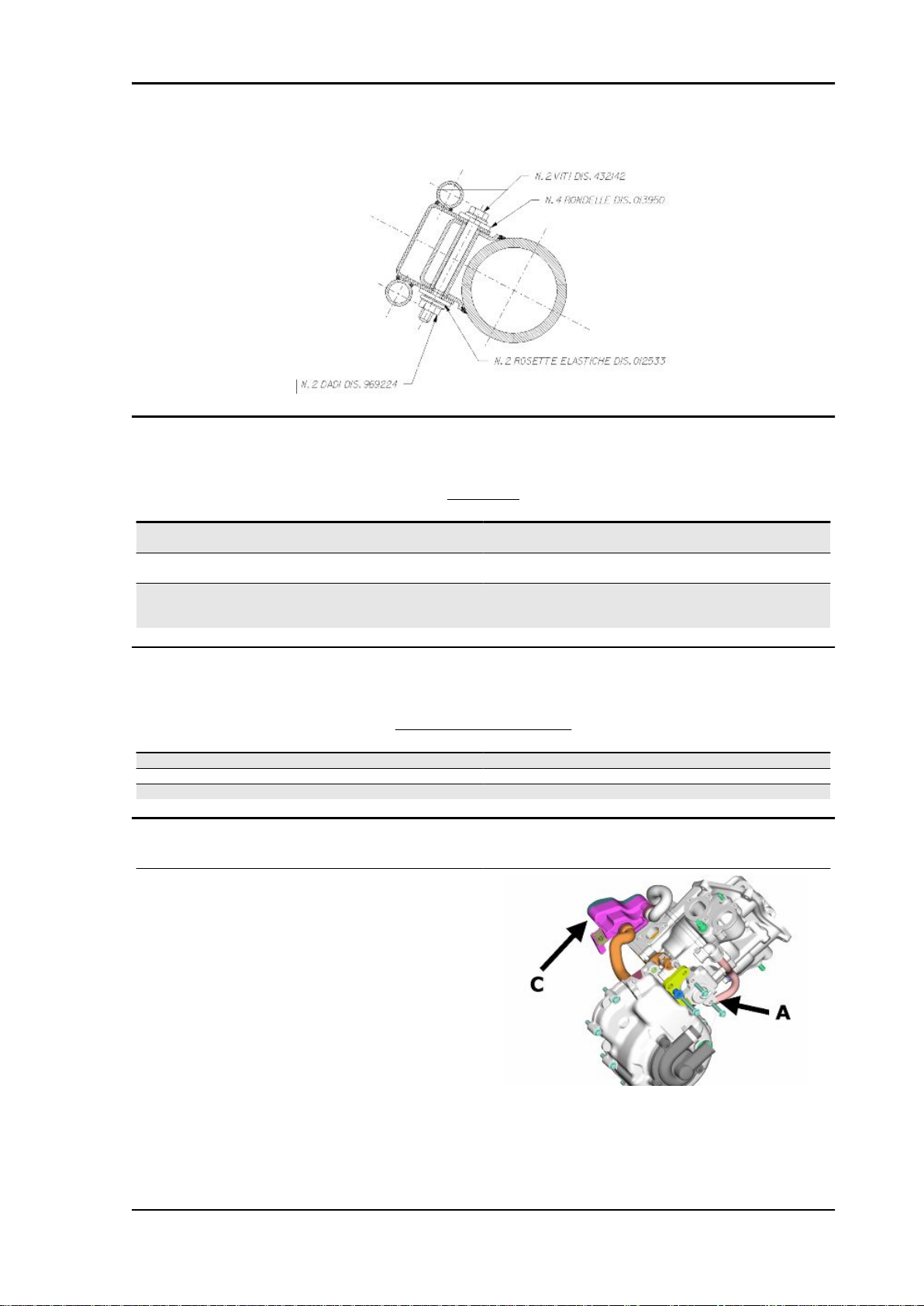
Please take note that, starting from chassis serial number ZAPM2300003509521, the front small chassis fixing system has changed in order to improve its locking to the chassis. Therefore we have
introduced:
• N°2 screws drawing 432142
• N°2 4x11x0 external teeth spring washers drawing 012533
CHAR - 10
Page 11
MSS X9 Evolution 250 Characteristics
• N°2 nuts drawing 968224
Brakes
BRAKES
Specification Desc./Quantity
Front Twin disc in stainless steel Ø 240 mm with dual-piston floating
Rear Ø 240 mm stainless steel disc with Brembo "Serie Oro" floating
Integral braking system Left lever acts on the left front and rear discs, through a valve
that distributes the pressure; the right lever acts on the right
calliper Ø 25.4 mm (front right and left)
calliper with Ø 34 mm twin plungers
front disc only
Wheels and tyres
WHEELS AND TYRES
Specification
Tyre pressure (when cold) Front: 2.1 bar Rear: 2.3 bar (2.5 bar with driver and luggage)
Tyres Front: 120/70-14" 55P Rear: 140/60-14" 64P
Light alloy rims Front rim: 3.50x14" Rear rim: 3.50x14"
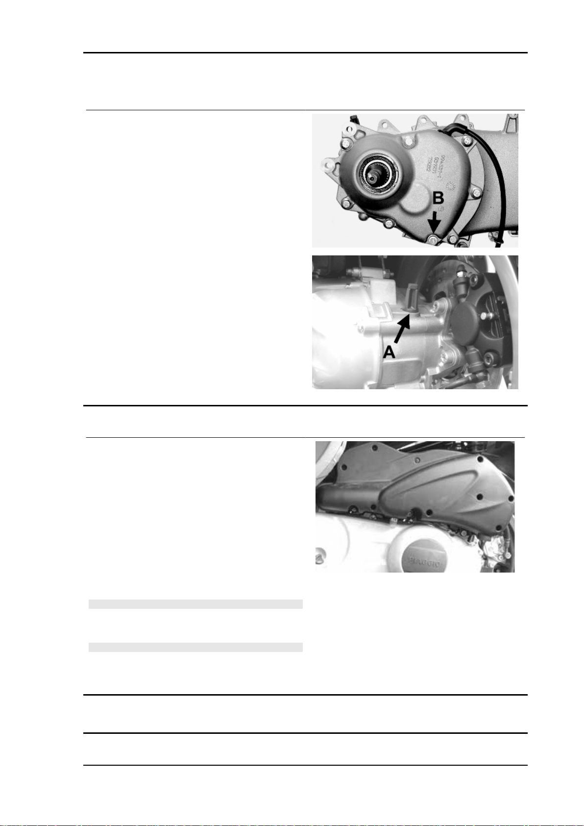
Secondary air
General notes:
The SAS for Quasar 250 Euro 2 engines operates
in a similar manner to the SAS for 2T engines.
The differences are the following:
instead of entering through the muffler as for 2T
engine, the secondary air enters directly in the discharge pipe on the head.
The 2T reed valve has a diaphragm. The unit
"A", indicated in the figure, has a cut-off device
Desc./Quantity
connected to the depression intake on the inlet
CHAR - 11
Page 12
Characteristics MSS X9 Evolution 250
manifold that cuts the air inlet in deceleration, to
avoid explosions in the muffler.
System description:
Air is sucked in through the hole "B" and gets
through the tube into the filter housing "C" where
the filtering element "D"is.
Now, the filtered air enters the diaphragm device
"A" and then is channelled to the head.
The air passes through a flanged pipe "E"connec-
ted to the air head and reaches a discharge joint
in order to supply oxygen to the unburned gases
before the catalytic converter, thus favouring an
improved reaction of the catalytic converter.
Carburettor
250cc Version
Keihin
Depression carburettor CVEK-30
Tapered pin notches position from top Fixed position
Starter device resistance ~ 20 Ω
CHAR - 12
KEHIN CARBURETTOR
Specification
Body stamping CVEK
Stamping 303A
Max. air jet 70
Diffuser nozzle Ø 2.8
Starter jet 42
Diffuser Ø 29
Desc./Quantity
Page 13

MSS X9 Evolution 250 Characteristics
Specification Desc./Quantity
Tapered pin stamping NDWA
Minimum mixture set screw initial opening ± ¼
Throttle valve spring 150 ÷ 250 g
Minimum air jet 115
Minimum jet 38
Max. jet 100
Starter air jet Ø 1.5 (body)
Starter diffuser nozzle Ø 1.5 (body)
N.B.
THE IDENTIFICATION LETTER CAN VARY WITH EACH CARBURETTOR UPDATE
Walbro
WALBRO CARBURETTOR
Specification Desc./Quantity
Tapered pin notches position from top 3
Tapered pin stamping 465
Minimum mixture set screw initial opening 3 ± 1/4
Throttle valve spring 120 g
Minimum air jet 50
Max. air jet 150
Minimum jet 34
Max. jet 118
Body stamping 7HO
Vacuum type WVF-7H*
Diffuser Ø 29 (30.3x27.0)
Starter jet 50
Starter diffuser jet 130
Starter air jet 200
Diffuser nozzle Ø 2.7
Stamping
N.B.
THE IDENTIFICATION LETTER CAN VARY WITH EACH CARBURETTOR UPDATE
Tightening Torques
Product
(°) Loctite 243 Medium-strength threadlock Apply LOCTITE 243 medium-strength
Name
Oil bleed screw 8÷12
Disc tightening screw (°) 5 - 6
Brake fluid pipe-calliper fitting 16 ÷ 20
Brake fluid pump-hose fitting 16 ÷ 20
Tightening screw for calliper support to the fork 45 ÷ 55
Name
Upper shock absorber clamp 33 ÷ 41
Lower shock absorber clamp 33 ÷ 41
Rear wheel axle 104 ÷ 126
Name
Fork leg screw 6 ÷ 7
REAR BRAKE
Description Specifications
threadlock
FRONT BRAKE
Torque in Nm
REAR SUSPENSION
Torque in Nm
FRONT SUSPENSION
Torque in Nm
CHAR - 13
Page 14

Characteristics MSS X9 Evolution 250
Name Torque in Nm
Front wheel axle 45 ÷ 50
Fork plate screw 25 ÷ 34
CHASSIS
Name Torque in Nm
Centre stand bolt 25 ÷ 30
Frame arm-engine arm bolt 60 ÷ 64
Swinging arm buffer nut 20 ÷ 25
Frame-swinging arm bolt 66 ÷ 80
Engine-swinging arm bolt 33 ÷ 41
STEERING
Name Torque in Nm
Upper steering ring nut 30 ÷ 36
Steering lower ring nut 10 ÷ 13 then loosen by 90°
Handlebar fixing screw (*) 45 ÷ 50
Fixing screws for handlebar control assembly U-bolts 7 ÷ 10
ENGINE - COOLING
Product Description Specifications
(°) Loctite 243 Medium-strength threadlock Apply LOCTITE 243 medium-strength
threadlock
CRANKCASE AND CRANKSHAFT
Name
Internal engine crankcase bulkhead (transmission-side half
shaft) screws
Engine-crankcase coupling screws 11 ÷ 13
Starter motor screws 11 ÷ 13
Crankcase timing system cover screws (°) 3.5 ÷ 4.5
ENGINE - FLYWHEEL
Name
Pick-Up clamping screws 3 ÷ 4
Stator assembly screws (°) 3 ÷ 4
Flywheel cover fixing screws 5 - 6
Flywheel nut (250) 94 ÷ 102
Screw fixing freewheel to flywheel 13 ÷ 15
ENGINE - TRANSMISSION
Name
Rear hub cover screws 24 ÷ 27
Driven pulley shaft nut 54 ÷ 60
Transmission cover screws 11 ÷ 13
Drive pulley nut 75 ÷ 83
Clutch unit nut on driven pulley 55 ÷ 60
Belt support roller screw 11 ÷ 13
ENGINE - CYLINDER HEAD
Name
Manifold-silencer retaining bolt 15 ÷ 20
Nut fixing muffler to cylinder head 16 ÷ 18
Camshaft retention plate screw 4 ÷ 6
Timing chain tensioner central screw 5 - 6
Timing chain tensioner support screw 11 ÷ 13
Starter ground support screw 11 ÷ 15
Timing chain tensioner slider screw 10 ÷ 14
Inlet manifold screws 11 ÷ 13
Tappet set screw lock nut 6 ÷ 8
Starter ground screw 7 ÷ 8.5
Head fixing side screws 11 ÷ 12
Torque in Nm
4 ÷ 6
Torque in Nm
Torque in Nm
Torque in Nm
CHAR - 14
Page 15

MSS X9 Evolution 250 Characteristics
Name Torque in Nm
Nuts fixing head to cylinder (*) 27 ÷ 29
Tappet cover screws 6 ÷ 7
Spark plug 12 ÷ 14
LUBRICATION
Name Torque in Nm
Hub oil drainage plug 15 ÷ 17
Oil filter on crankcase fitting 27 ÷ 33
Engine oil drainage plug/mesh filter 24 ÷ 30
Oil filter 4 ÷ 6
Oil pump cover screws 0.7 ÷ 0.9
Screws fixing oil pump to crankcase 5 - 6
Oil pump control crown screw 10 ÷ 14
Oil pump cover plate screws 4 ÷ 6
Oil sump screws 10 ÷ 14
Minimum oil pressure sensor 12 ÷ 14
N.B.
Before fitting the nuts, lubricate them with engine oil
N.B.
Use new nuts
NOTE DI ASSISTENZA TECNICA
For correct tightening, the expansion tank cap locking torque has been standardised to 2.5 Nm
Overhaul data
Assembly clearances
Cylinder - piston assy.
COUPLING CATEGORIES ENGINE 250
Name
Cylinder / piston A 71.990 ÷ 71.997 71.953 ÷ 71.960 0.030 - 0.044
Cylinder / piston B 71.997 ÷ 72.004 71.960 ÷ 71.967 0.030 - 0.044
Cylinder / piston C 72.004 ÷ 72.011 71.967 ÷ 71.974 0.030 - 0.044
Cylinder / piston D 72.011 ÷ 72.018 71.974 ÷ 71.981 0.030 - 0.044
Initials Cylinder Piston Play on fitting
CHAR - 15
Page 16
Characteristics MSS X9 Evolution 250
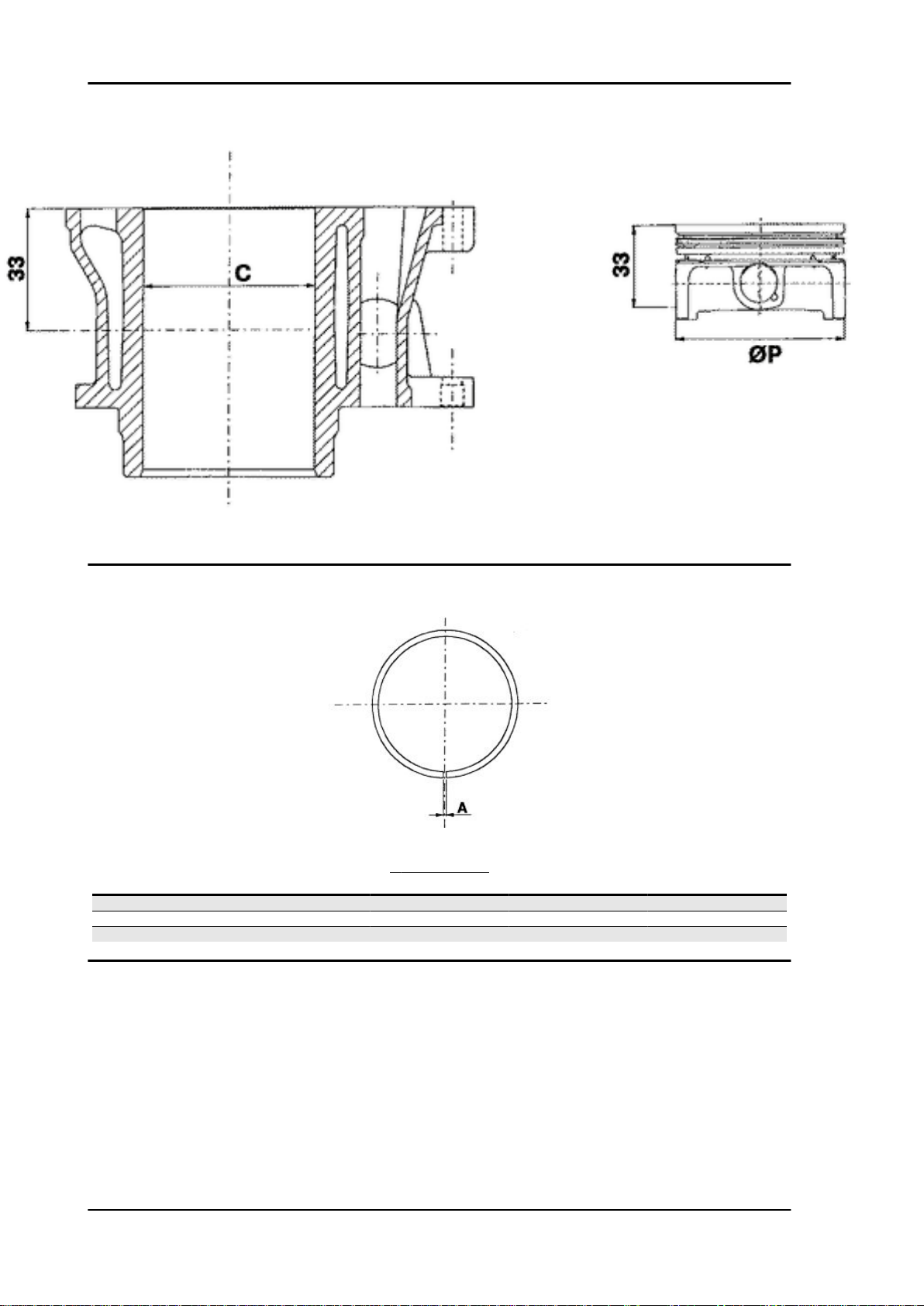
Piston rings
SEALING RINGS
Name
Compression ring 72 x 1.5 A 0.15 ÷ 0.30
Oil scraper ring 72 x 1 A 0.20 ÷ 0.40
Oil scraper ring 72 x 2.5 A 0.20 ÷ 0.40
Description Dimensions Initials Quantity
CHAR - 16
Page 17
MSS X9 Evolution 250 Characteristics
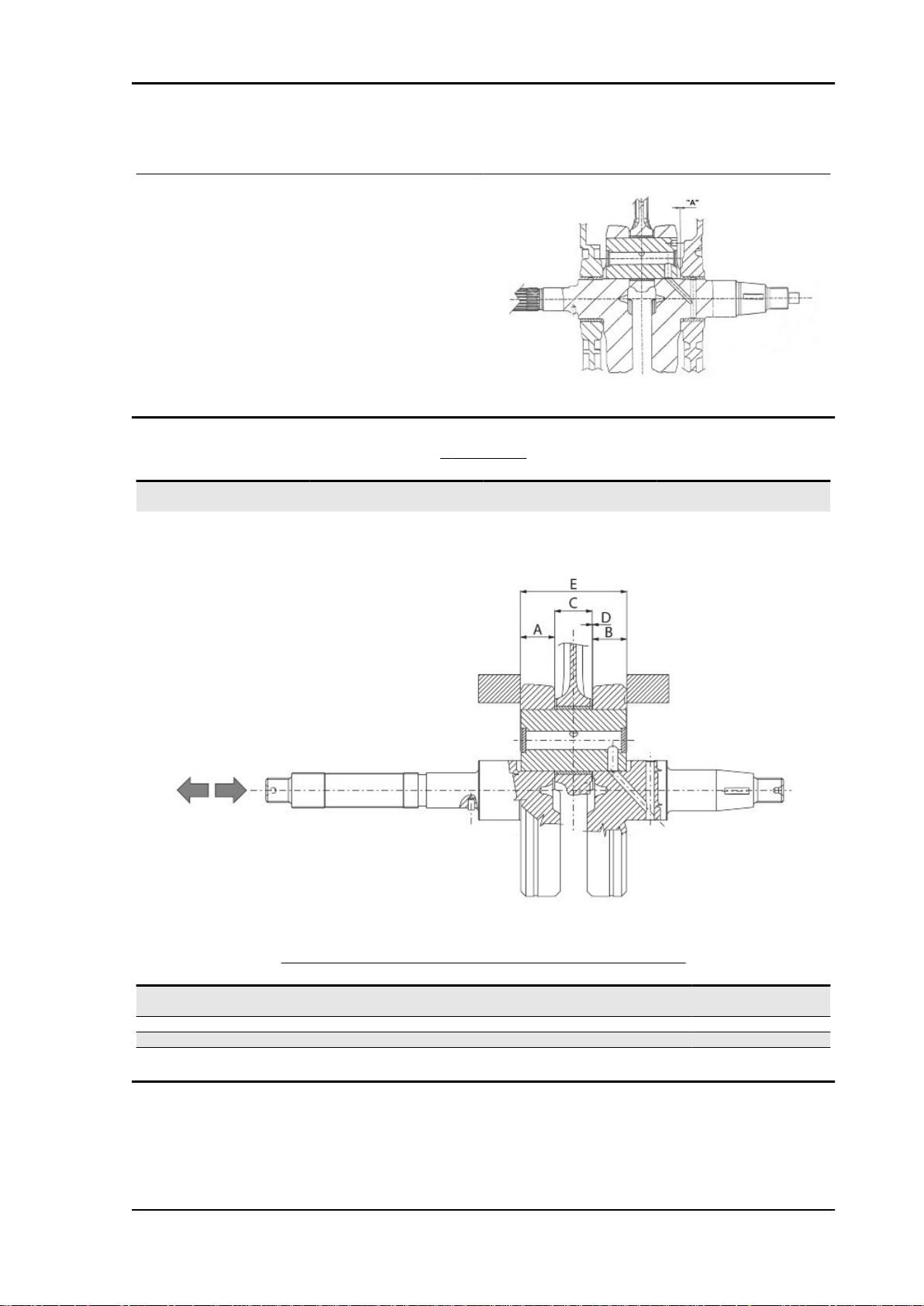
Crankcase - crankshaft - connecting rod
Characteristic
Driving shaft / crankcase axial clearance
A= 0,15 ÷ 0,43 (when cold)
CRANKSHAFT
Titolo Durata/Valore Testo Breve (< 4000 car.) Indirizzo Immagine
Crankshaft Crankshaft to crankcase axial
Crankshaft to crankcase axial clearance
clearance
CRANKSHAFT/ CRANKCASE AXIAL CLEARANCE
Name
Half-shaft, transmission
side
Flywheel-side half-shaft 16.6 +0-0.05 B D = 0.20 - 0.50
Connecting rod 18 -0.10 -0.15 C D = 0.20 - 0.50
Spacer tool 51.4 +0.05 E D = 0.20 - 0.50
Description Dimensions Initials Quantity
16.6 +0-0.05 A D = 0.20 - 0.50
CHAR - 17
Page 18
Characteristics MSS X9 Evolution 250
Slot packing system
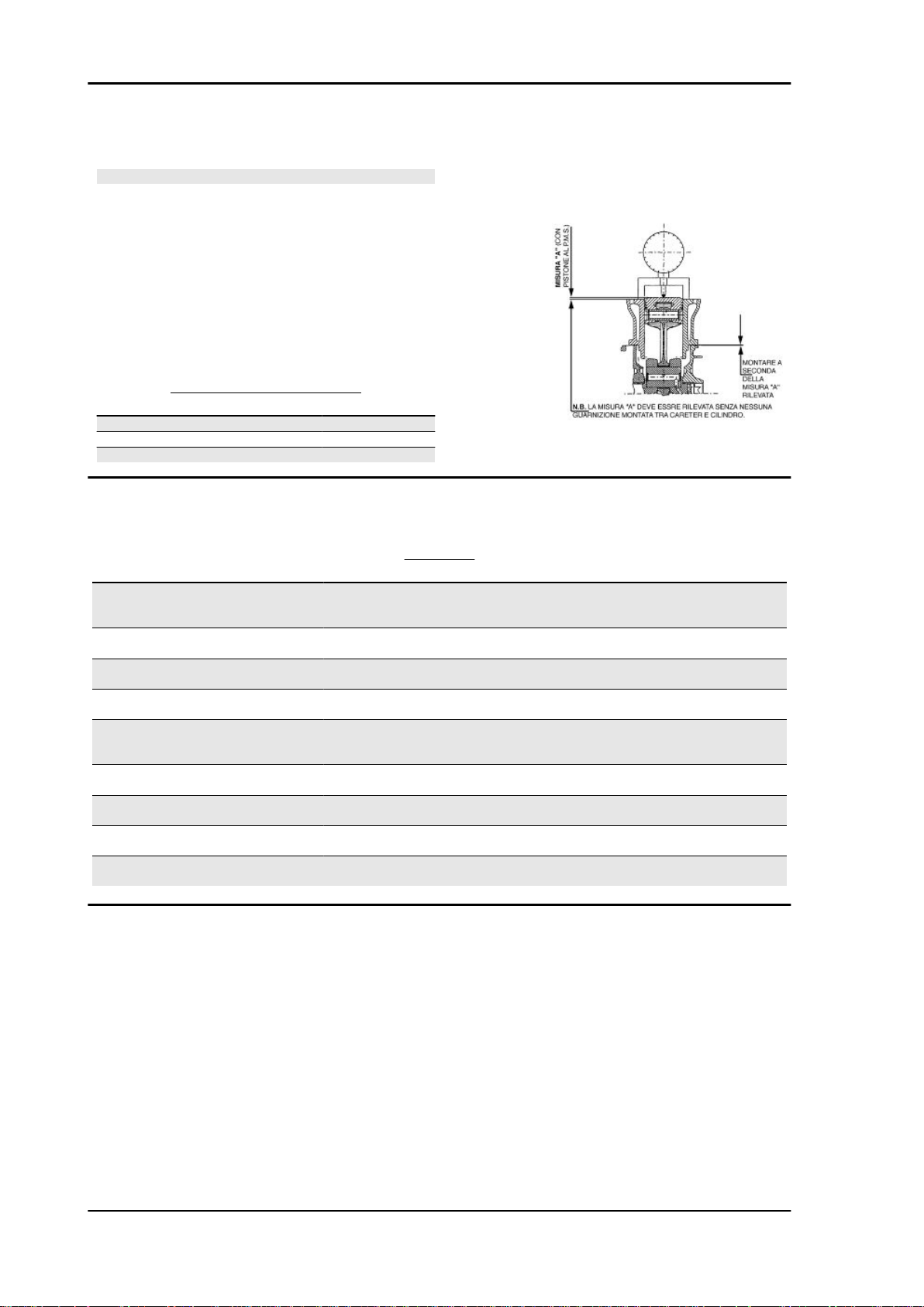
N.B.
MEASUREMENT "A" TO BE TAKEN IS A VALUE OF PISTON RE-ENTRY, IT INDICATES BY
HOW MUCH THE PLANE FORMED BY THE PISTON CROWN FALLS BELOW THE PLANE
FORMED BY THE TOP OF THE CYLINDER. THE
FURTHER THE PISTON FALLS INSIDE THE
CYLINDER, THE LESS THE BASE GASKET IS
TO BE APPLIED (TO RECOVER THE COMPRESSION RATIO) AND VICE VERSA.
ENGINE 250 SHIMMING
Name Measure A Thickness
shimming 3.70 - 3.60 0.4 ± 0.05
shimming 3.60 - 3.40 0.6 ± 0.05
shimming 3.40 - 3.30 0.8 ± 0.05
Products
PRODUCTS
Product
AGIP GREASE PV2 Grease for steering bearings and spindle
MONTBLANC MOLYBDENUM
GREASE
AGIP FILTER OIL Oil for air filter sponge Mineral oil with specific additives for in-
AGIP GREASE MU3 Grease for odometer transmission gear
AGIP CITY HI TEC 4T Engine oil SAE 5W-40 Synthetic oil that exceed the
AGIP GP 330 Calcium complex soap-based grease
AGIP CITY HI TEC 4T Four-stroke engine oil Lubricating oil for flexible shafts (throttle
AGIP ROTRA 80W-90 Rear hub oil SAE 80W/90 Oil that exceeds the re-
AGIP PERMANENT SPEZIAL coolant Monoethylene glycol-based antifreeze
Grease for driven pulley shaft adjusting
ring and movable driven pulley housing
Description Specifications
seats
case
with NLGI 2; ISO-L-XBCIB2
Soap-based lithium and zinc oxide
grease containing NLGI 2; ISO-L-
XBCIB2 of the swinging arm
Grease with Molybdenum disulphide
creased adhesiveness
Soap-based lithium grease with NLGI 3;
ISO-L-XBCHA3, DIN K3K-20
requirements of API SL, ACEA A3, JASO
Grease (brake control levers, throttle
quirements of API GL3 specifications
fluid, CUNA NC 956-16
MA specifications
grip)
control)
CHAR - 18
Page 19

INDEX OF TOPICS
TOOLING TOOL
Page 20
Tooling MSS X9 Evolution 250
ATTREZZATURA SPECIFICA
Stores code Description
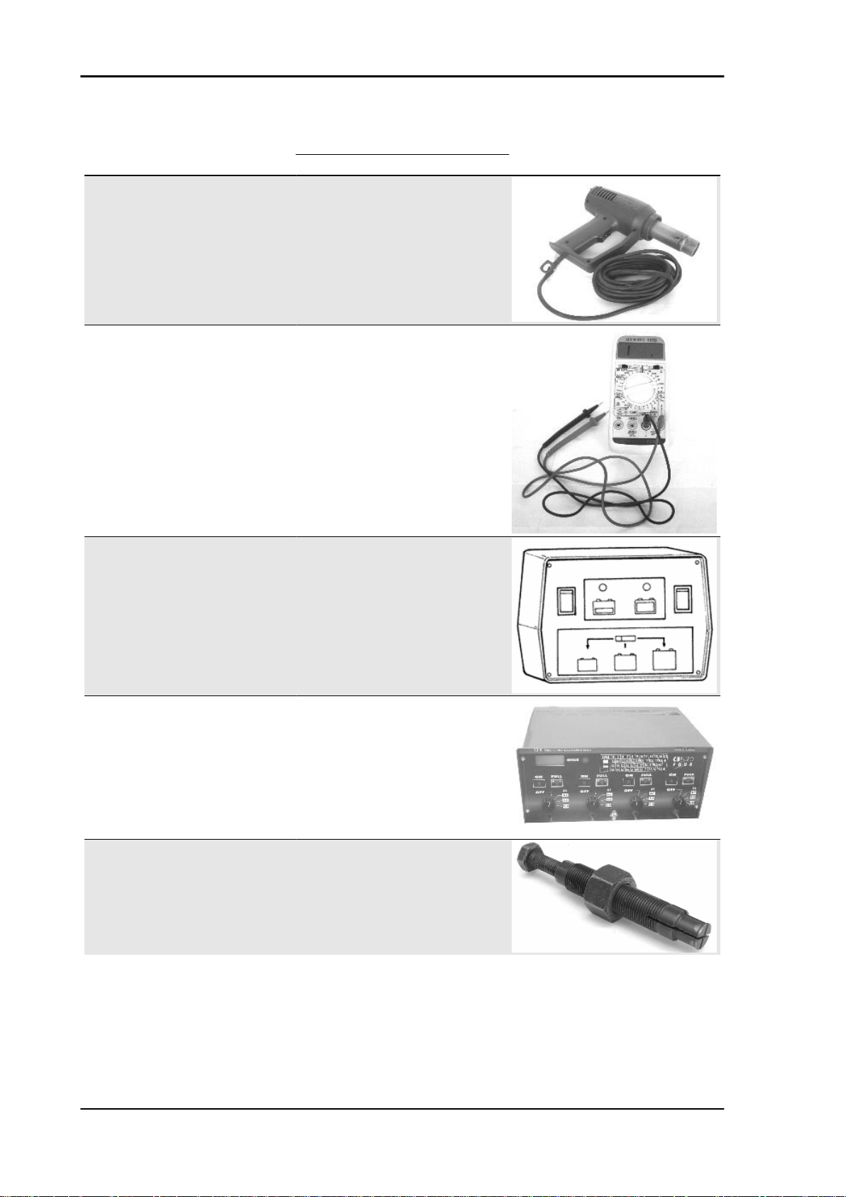
020151Y Air heater
020331Y Digital multimeter
020333Y Single battery charger
020334Y Multiple battery charger
001467Y014 Pliers to extract ø 15-mm bearings
TOOL - 20
Page 21
MSS X9 Evolution 250 Tooling
Stores code Description
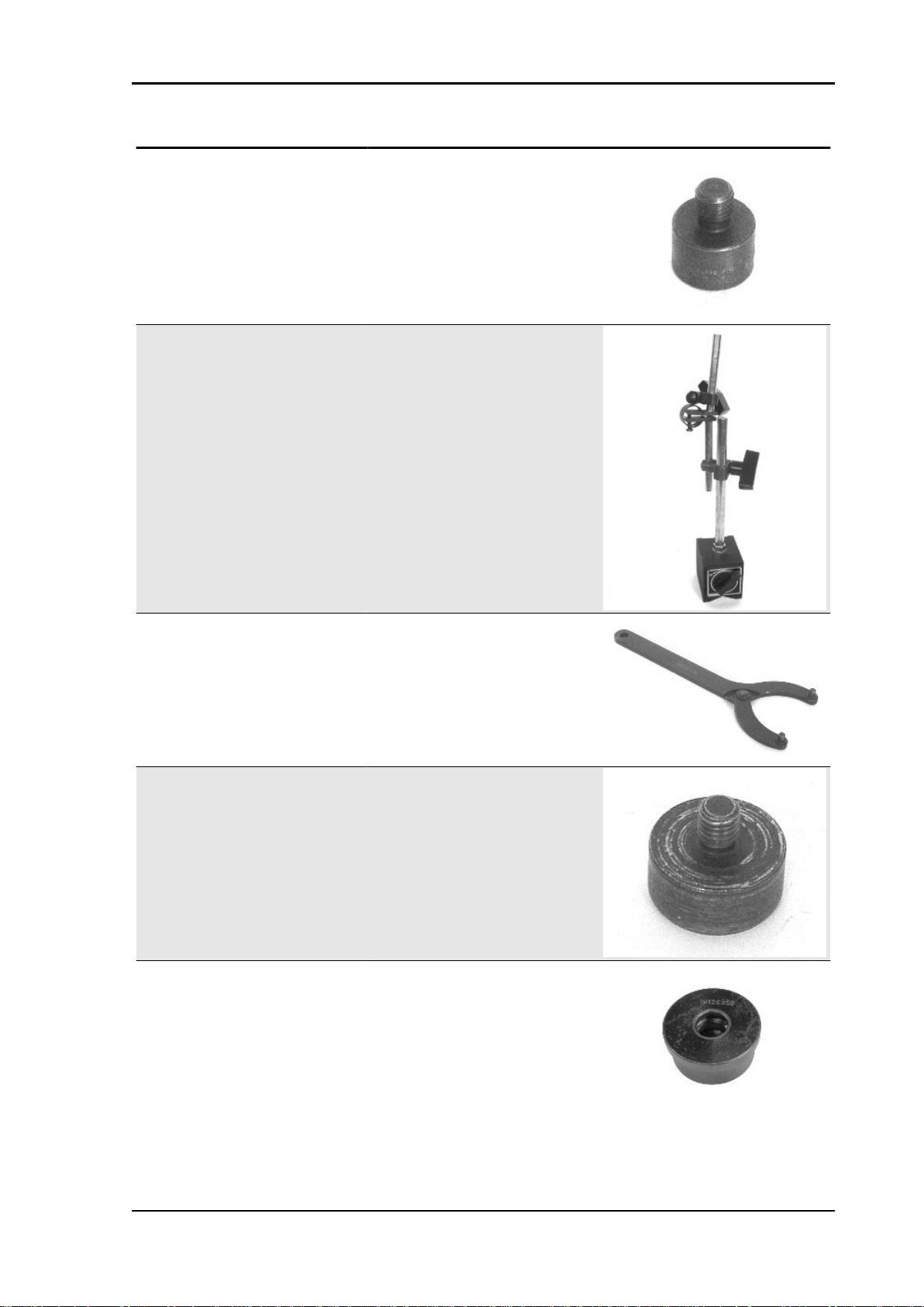
020412Y 15 mm guide
020335Y Magnetic support for dial gauge
020565Y Flywheel lock calliper spanner
020439Y 17 mm guide
020359Y 42x47-mm adaptor
TOOL - 21
Page 22
Tooling MSS X9 Evolution 250
Stores code Description
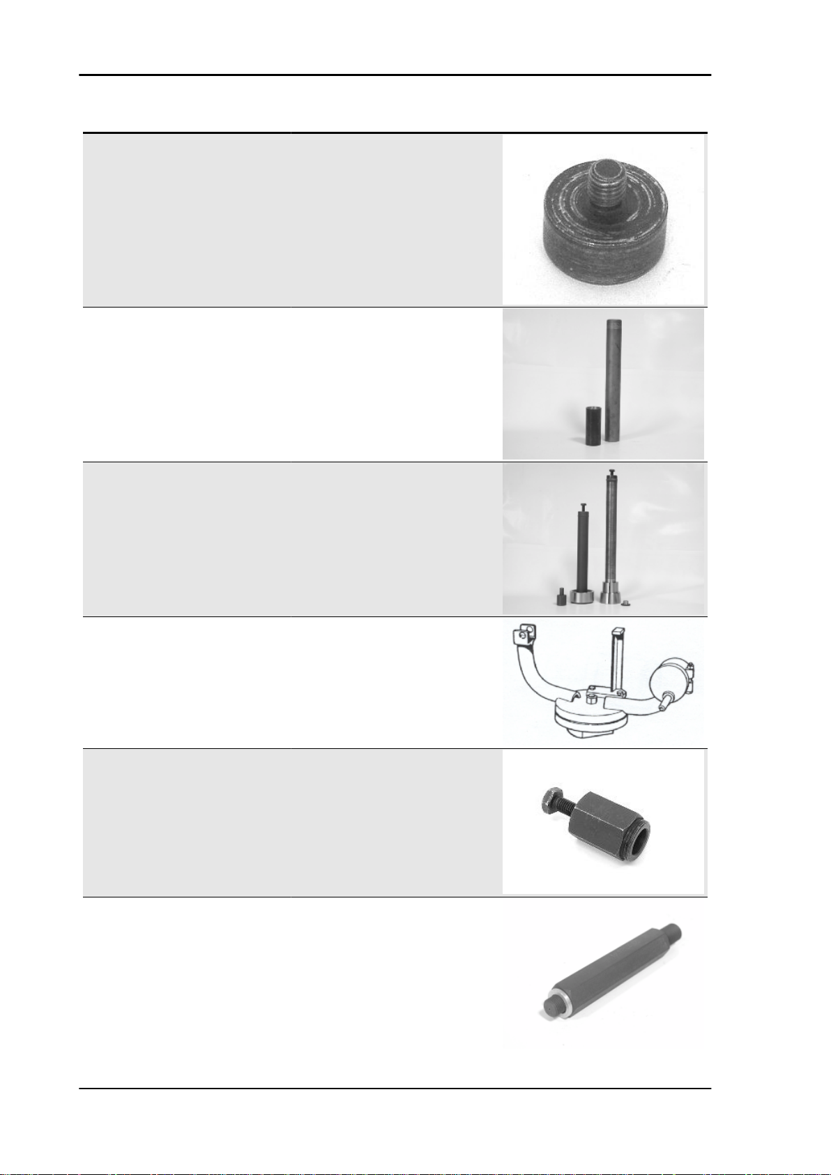
020363Y 20 mm guide
020459Y Punch for fitting bearing on steering tube
020458Y Puller for lower bearing on steering tube
005095Y Engine support
008564Y Flywheel extractor
TOOL - 22
020434Y Oil pressure control fitting
Page 23

MSS X9 Evolution 250 Tooling
Stores code Description
020382Y011 adapter for valve removal tool
020424Y Driven pulley roller casing fitting punch
020431Y Valve oil seal extractor
020193Y Oil pressure gauge
020306Y Punch for assembling valve seal rings
020360Y Adaptor 52 x 55 mm
TOOL - 23
Page 24
Tooling MSS X9 Evolution 250
Stores code Description
020364Y 25-mm guide
020375Y Adaptor 28 x 30 mm
020376Y Adaptor handle
020444Y Tool for fitting/ removing the driven pulley
020330Y Stroboscopic light to check timing
clutch
TOOL - 24
001467Y035 Belle for OD 47-mm bearings
Page 25
MSS X9 Evolution 250 Tooling
Stores code Description
020368Y driving pulley lock wrench
020319Y Immobilizer check tester
020287Y Clamp to assemble piston on cylinder
020263Y Sheath for driven pulley fitting
020262Y Crankcase splitting strip
020430Y Pin lock fitting tool
TOOL - 25
Page 26
Tooling MSS X9 Evolution 250
Stores code Description
020428Y Piston position check support
020426Y Piston fitting fork
020425Y Punch for flywheel-side oil seal
020423Y driven pulley lock wrench
020414Y 28-mm guide
020393Y Piston fitting band
TOOL - 26
Page 27
MSS X9 Evolution 250 Tooling
Stores code Description
020382Y Valve cotters equipped with part 012 re-
020455Y 10-mm guide
020442Y Pulley lock wrench
moval tool
020329Y MityVac vacuum-operated pump
020357Y Adaptor 32 x 35 mm
020409Y Multimeter adaptor - Peak voltage detec-
tion
TOOL - 27
Page 28
Tooling MSS X9 Evolution 250
Stores code Description
020456Y Ø 24 mm adaptor
020332Y Digital rev counter
020074Y Support base for checking crankshaft
020055Y Wrench for steering tube ring nut
002465Y Pliers for circlips
alignment
TOOL - 28
001330Y Tool for fitting steering seats
Page 29
MSS X9 Evolution 250 Tooling
Stores code Description
020454Y Tool for fitting piston pin stops (200 - 250)
020622Y Transmission-side oil guard punch
020444Y011 adapter ring
020444Y009 46x55 Wrench
001467Y Extractor for bearings for holes
001467Y013 Pliers to extract ø 15-mm bearings
TOOL - 29
Page 30
Tooling MSS X9 Evolution 250
Stores code Description
020444Y010 adapter ring
020628Y Water pump service kit
TOOL - 30
Page 31

INDEX OF TOPICS
MAINTENANCE MAIN
Page 32

Maintenance MSS X9 Evolution 250
Maintenance chart
Safety tightenings: refer to the chapter "Predelivery Operations"
AT 1000 KM OR 4 MONTHS
Action
Engine oil - replacement
Hub oil - change
Engine oil - change
Idle speed (*) - adjustment
Throttle lever - adjustment
Steering - adjustment
Brake control levers - greasing
Brake pads - check condition and wear
Brake fluid level - check
Safety locks - check
Electrical system and battery - check
Tyre pressure and wear - check
Vehicle and brake test - road test
(*) See rules in the «Adjusting the engine idle» section
AT 6000 KM OR 12 MONTHS
engine oil- change(125)
Hub oil level - check
Spark plug/ electrode gap - check
Air filter - clean
oil filter - change(125)
valve clearance 125 - check
Sliding blocks / variable speed rollers - check
Driving belt - checking
Coolant level - check
Brake pads - check condition and wear
Brake fluid level - check
Electrical system and battery - check
Tyre pressure and wear - check
Vehicle and brake test - road test
AT 12000 KM OR 24 MONTHS AND AT 60000 KM
Engine oil - replacement
Hub oil level - check
Spark plug / electrode gap - check / replacement
Air filter - clean
Engine oil - change
Idle speed (*) - adjustment
Sliding block / variable speed rollers - change
Throttle lever - adjustment
Coolant level - check
Steering - adjustment
Brake control levers - greasing
Brake pads - check condition and wear
Brake fluid level - check
Transmission elements - lubrication
Safety locks - check
Suspensions - check
Electrical system and battery - check
Headlight - adjustment
Tyre pressure and wear - check
Vehicle and brake test - road test
Transmission Belt (125 cc) - Replacement
Transmission Belt - Check (250)
Action
Action
MAIN - 32
Page 33

MSS X9 Evolution 250 Maintenance
(*) See rules in the «Adjusting the engine idle» section
AT 18000 KM AND AT 54000 KM
Action
engine oil- change(125)
Hub oil level - check
Spark plug/ electrode gap - check
Air filter - clean
oil filter - change(125)
valve clearance 125 - check
250 cc Valve Play - Check
Sliding blocks / variable speed rollers - check
Coolant level - check
Radiator - external cleaning/ check
Brake pads - check condition and wear
Brake fluid level - check
Electrical system and battery - check
Tyre pressure and wear - check
Vehicle and brake test - road test
Secondary air filter (250) - Cleaning
Transmission Belt - Replacement (250)
Transmission Belt (125 cc) - Replacement
AT 24000 KM AND AT 48000 KM
Engine oil - replacement
Hub oil - change
Spark plug / electrode gap - check / replacement
Air filter - clean
Engine oil - change
Idle speed (*) - adjustment
Sliding block / variable speed rollers - change
Throttle lever - adjustment
Coolant level - check
Steering - adjustment
Brake control levers - greasing
Brake pads - check condition and wear
Brake fluid level - check
Transmission elements - lubrication
Safety locks - check
Suspensions - check
Electrical system and battery - check
Headlight - adjustment
Tyre pressure and wear - check
Vehicle and brake test - road test
Transmission Belt - Check (250)
Transmission Belt (125 cc) - Replacement
(*) See rules in the «Adjusting the engine idle» section
AT 30000 KM, AT 42000 KM AND AT 66000 KM
Hub oil level - check
Spark plug/ electrode gap - check
Air filter - clean
Variable speed rollers - check or replacement
Driving belt - checking
Coolant level - check
Brake pads - check condition and wear
Brake fluid level - check
Electrical system and battery - check
Tyre pressure and wear - check
Vehicle and brake test - road test
engine oil- change(125)
oil filter - change(125)
Action
Action
MAIN - 33
Page 34

Maintenance MSS X9 Evolution 250
AT 36000 KM
Action
Engine oil - replacement
Hub oil level - check
Spark plug / electrode gap - check / replacement
Air filter - clean
Engine oil - change
valve clearance 125 - check
250 cc Valve Play - Check
Idle speed (*) - adjustment
Sliding block / variable speed rollers - change
Throttle lever - adjustment
Driving belt - replacement
Coolant level - check
Radiator - external cleaning/ check
Steering - adjustment
Brake control levers - greasing
Brake pads - check condition and wear
Brake fluid hoses - replacement
Brake fluid level - check
Transmission elements - lubrication
Safety locks - check
Suspensions - check
Electrical system and battery - check
Headlight - adjustment
Tyre pressure and wear - check
Secondary air filter (250) - Cleaning
Vehicle and brake test - road test
(*) See rules in the «Adjusting the engine idle» section
Engine oil - replacement
Hub oil - change
Spark plug / electrode gap - check / replacement
Air filter - clean
Engine oil - change
valve clearance 125 - check
250 cc Valve Play - Check
Idle speed (*) - adjustment
Sliding block / variable speed rollers - change
Throttle lever - adjustment
Driving belt - replacement
Coolant level - check
Radiator - external cleaning/ check
Steering - adjustment
Brake control levers - greasing
Brake pads - check condition and wear
Brake fluid hoses - replacement
Brake fluid level - check
Transmission elements - lubrication
Safety locks - check
Suspensions - check
Electrical system and battery - check
Headlight - adjustment
Tyre pressure and wear - check
Secondary air filter (250) - Cleaning
Vehicle and brake test - road test
(*) See rules in the «Adjusting the engine idle» section
AT 72000 KM
Action
Coolant - change
Brake fluid - change
MAIN - 34
EVERY 2 YEARS
Action
Page 35
MSS X9 Evolution 250 Maintenance
Action
Secondary air filter (external/internal) - cleaning (125)
EVERY 3,000 KM
10'
Action
Engine oil - level check/ top-up
Carburettor
- Disassemble the carburettor in its parts, wash all of them with solvent, dry all body grooves with
compressed air to ensure adequate cleaning.
- Check carefully that the parts are in good condition.
- The throttle valve should move freely in the chamber. Replace it in case of excessive clearance due
to wear.
- If there are wear marks in the chamber causing inadequate tightness or a free valve slide (even if it
is new), replace the carburettor.
- It is advisable to replace the gaskets at every refit
WARNING
PETROL IS HIGHLY EXPLOSIVE ALWAYS REPLACE THE GASKETS TO AVOID PETROL LEAKS
Checking the spark advance
- To check the ignition advance, use the stroboscopic lamp with induction collet connected to the
spark plug power supply cable.
- Connect the induction collet according to the right
polarity (the arrow on the collet must be facing the
spark plug).
- Set the lamp selector to the central position (1
spark = 1 driving shaft revolution as in 2 stroke
engines).
- Start the engine and check that the lamp is in
good working order and that the rpm counter reads
high speeds too (e.g. 8,000 rpm).
- If you detect abnormal flashes or rpm reads, increase the resistive load on the spark plug supply
line (10 - 15 KΩ in series with the H.V. cable).
- Remove the slit plastic cap on the flywheel cover.
- Adjust the lamp flash dephasing corrector to
make the reference on the flywheel cover collimate
with the level on the water pump drive. Read the
MAIN - 35
Page 36

Maintenance MSS X9 Evolution 250
advance degrees indicated by the stroboscopic
lamp.
- Check that the advance degrees match the revolution speed as indicated in the tables.
- In case of abnormal values, check the Pick-Up
and the control unit supplies (positive-negative);
replace the control unit, if required.
- A new control unit prevents the engine from rotating at over 2,000 rpm.
- The programmed control unit allows the engine
revolution within the prescribed limits.
Specific tooling
020330Y Stroboscopic light to check timing
Characteristic
250 spark advance check
10° ± 1° at 2000 Rpm
32° ± 1° at 6000 Rpm
Spark advance variation
Characteristic
Operation threshold
First threshold : 9600±50
Second threshold : 9800±50
Reactivation threshold
First threshold : 9500±50
Second threshold : 9700±50
Spark elimination
First threshold : 1 spark on 7
Second threshold : 2 sparks on 3
MAIN - 36
Page 37

MSS X9 Evolution 250 Maintenance
Spark plug
To inspect the spark plug the engine must be cold;
proceed as follows:
- Remove the saddle after loosening the knob located into the rear trunk.
- Remove the spark plug cap.
- Using the supplied spanner (provided with retain
rubber cap), remove the spark plug.
- Disconnect the spark plug lug and remove it.
- Inspect it carefully; if the insulator is damaged or
chipped, replace it.
- Measure the distance between the electrodes
using a thickness gauge, if required, adjust it by
carefully bending the external electrode.
- Make sure that the sealing washer is in good
working order.
MAIN - 37
Page 38

Maintenance MSS X9 Evolution 250
- Install the spark plug, tighten by hand and then
lock it by the special wrench at the prescribed torque.
CAUTION
THE SPARK PLUG MUST BE REMOVED WHEN THE MO-
TOR IS COLD. THE SPARK PLUG MUST BE REPLACED
EVERY 12,000 KM. THE USE OF NON CONFORMING IGNITION CONTROL UNITS OR SPARK PLUGS OTHER THAN
THOSE PRESCRIBED CAN SERIOUSLY DAMAGE THE ENGINE.
Characteristic
Spark plug: electrode distance
0.7 mm ÷ 0.8 mm
Electric characteristic
Recommended spark plug:
CHAMPION RG4HC
Locking torques (N*m)
Spark plug 12 ÷ 14
Hub oil
Check
Level check:
- Move the vehicle to a flat ground and rest it on the stand.
- Unscrew the oil bar, dry it with a clean cloth and reinsert it, screwing it in thoroughly.
- Extract the bar and check that the oil level reaches the second notch of the bar from the bottom.
- Screw the oil bar back on, checking that it is tightly in place.
Recommended oil: TUTELA ZC 90
Tightening torque:
Drainage cap: 15 - 17 N·m
MAIN - 38
Page 39
MSS X9 Evolution 250 Maintenance
Replacement
Hub oil replacement
- Remove the oil loading cap «A».
- Remove the oil drainage cap «B» and let the oil
drain out completely.
- Tighten the drainage cap again and fill the hub
with oil (about 150 cc.).
Air filter
Remove the air cleaner cap after undoing the retainer screws, then extract the filter.
- Wash with water and neutral soap.
-Dry with a clean cloth and short blasts of compressed air.
- Soak with a mixture of 50% petrol and 50% SE-
LENIA AIR FILTER OIL.
-Drip dry the filter and then squeeze it between the
hands without wringing.
CAUTION
NEVER RUN THE ENGINE WITHOUT THE AIR FILTER,
THIS WOULD RESULT IN AN EXCESSIVE WEAR OF THE
PISTON AND CYLINDER.
CAUTION
WHEN TRAVELLING ON DUSTY ROADS, THE AIR FILTER
MUST BE CLEANED MORE OFTEN THAN SHOWN IN THE
SCHEDULED MAINTENANCE CHART.
Engine oil
MAIN - 39
Page 40

Maintenance MSS X9 Evolution 250
Replacement
- Loosen the oil loading cap/bar.
- Loosen the network filter unloading cap «A» on
the flywheel side and let the oil drain out completely.
- Extract the oil cartridge «B» filter using the two
protruding tabs and remove it.
- Install a new oil filter lubricating the filter sealing
O-Ring with engine oil.
- Tighten the drainage cap again and fill with ~ 600
- 650 cc oil.
- Start the engine, let it run for a few minutes and
then stop it.
- Wait a few minutes, then remove the cap - bar
and check the level. Fill in with the prescribed oil
up to reach the MAX level.
Check
This operation must be carried out with the engine cold and following the procedure below:
1. Place the vehicle on its centre stand and on flat ground.
2. Undo cap/dipstick "A", dry it off with a clean cloth and replace it, screwing down completely.
3. Remove the cap/dipstick again and check that the level is between the min and max. marks; top
up if necessary.
The MAX level mark indicates a quantity of around 1300 cc of engine oil. If the check is carried out after
the vehicle has been used, and therefore with a hot engine, the level line will be lower; in order to carry
out a correct check, wait at least 10 minutes after the engine has been stopped so as to get the correct
level.
Oil top up
The oil should be topped up after having checked
the level and in any case by adding oil without
ever exceeding the MAX. level.
Restoration of the level from MIN to MAX requires
approximately 200 cc.
MAIN - 40
Page 41
MSS X9 Evolution 250 Maintenance
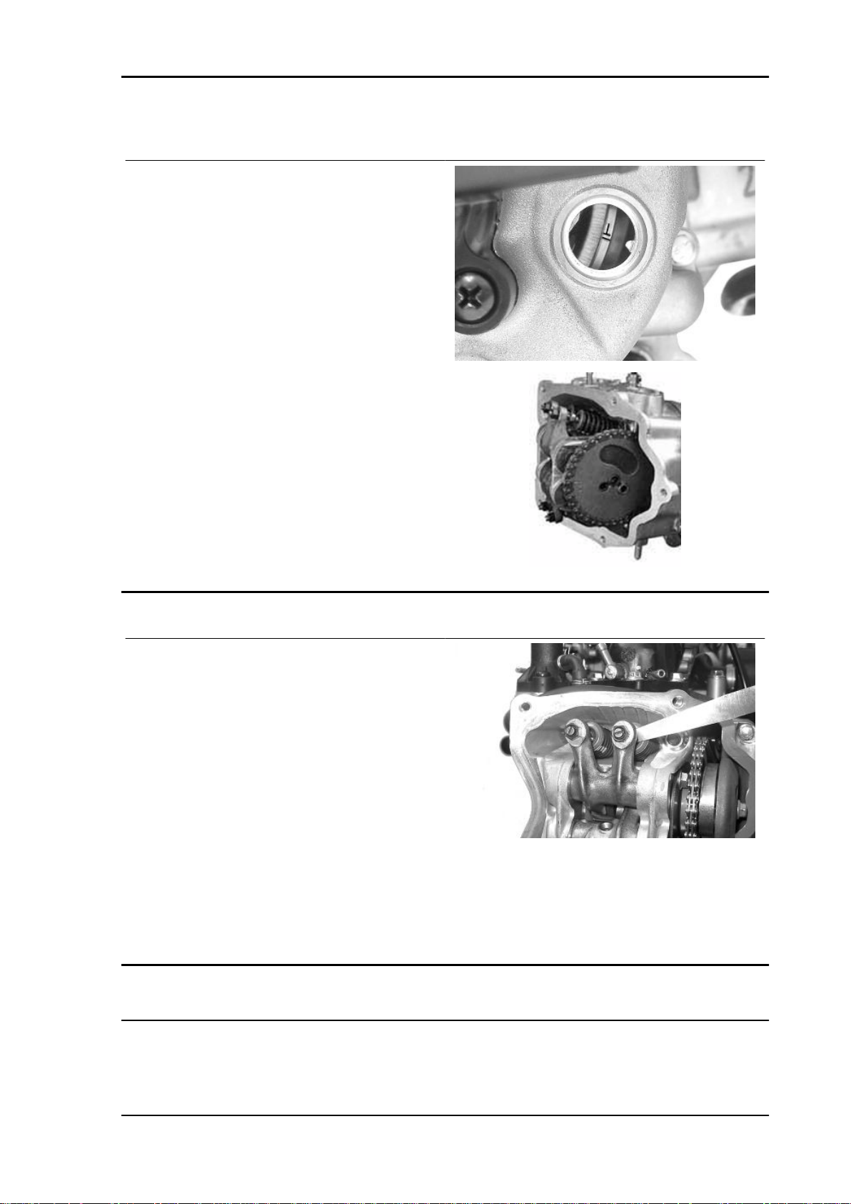
Checking the ignition timing
- Remove the plastic cap on the flywheel cover
-Turn the flywheel until the reference mark «T» on
the rotor matches the reference mark on the flywheel cover as shown in the figure (TDC). Make
sure that the 4V reference point on the camshaft
control pulley is aligned with the reference point on
the head as shown in the second figure. If the reference is opposite the indicator on the head, turn
the crankshaft once more.
For the use of this reference mark, remove the
spark plug and turn the engine in the direction that
is the reverse of the normal direction using a calliper spanner applied to the camshaft command
pulley casing.
Checking the valve clearance
-To check valve clearance, centre the reference
marks of the timing system
- Use a thickness gauge to check that the clearance between the valve and the register corresponds with the indicated values. When the valve
clearance values, intake and drainage respectively, are different from the ones indicated below,
adjust them by loosening the lock nut and operate
on the register with a screwdriver as shown in the
figure.
Intake: 0.10 mm (when cold)
Discharge: 0.15 mm (when cold)
Cooling system
MAIN - 41
Page 42

Maintenance MSS X9 Evolution 250
Level check
The engine is cooled by forced liquid circulation.
The cooling circuit holds 1.8 litres of a coolant
made up of 50% demineralised water and a solution of glycol-ethylene anti-freeze and corrosion
inhibitors.
The packaged coolant supplied is ready-mixed
and ready for use.
To ensure correct engine performance, the coolant temperature should be between 60°C min. and
105°C max. as indicated on the relevant instrument «D» with the coloured references on the
analogue instrument panel. If the needle goes into
the red , switch the engine off, allow it to cool then
check the coolant level. If the fluid is within the
normal limits, perform the cooling system checks.
The coolant level should be checked every 6,000
km with the engine cold, following the instruction
given below.
a) Put the vehicle in an upright position on the
kickstand.
b) Remove the expansion tank cap «A» by turning
it anti-clockwise.
c) Look inside the expansion tank: the minimum
and maximum levels are marked on the plastic inside the expansion tank.
d) Top up if the level of coolant is beneath the min.
level mark inside the expansion tank.
The coolant level must always be between the min.
and max. levels. If the coolant level is close to the
min. marking, top up as required when the engine
is cold. If frequent topping up is required or if the
expansion tank is completely dry, the cooling system needs to be investigated.
The coolant must be replaced every 2 years.
WARNING
MAIN - 42
Page 43

MSS X9 Evolution 250 Maintenance
IN ORDER TO AVOID BURNS, DO NOT UNSCREW THE
EXPANSION TANK CAP WHILE THE ENGINE IS STILL
HOT.
WARNING
IN ORDER TO AVOID HARMFUL FLUID LEAKS WHILE RIDING, IT IS IMPORTANT TO MAKE SURE THAT THE LEVEL
NEVER EXCEEDS THE MAXIMUM VALUE.
IN ORDER TO GUARANTEE THE PROPER FUNCTION OF
THE ENGINE, IT IS NECESSARY TO KEEP THE RADIATOR
GRILLE CLEAN.
Recommended products
AGIP PERMANENT SPEZIAL coolant
Monoethylene glycol-based antifreeze fluid, CUNA NC 956-16
Braking system
Level check
The front and rear brake fluid tanks are placed on
the pumps under the handlebar covers. Proceed
as follows:
1. Put the vehicle up on the central kickstand and
with the handlebar centred;
2. Remove cover «A» by unscrewing the fixing
screw «B»;
3. Check the fluid level using the relevant window
«C».
MAIN - 43
Page 44

Maintenance MSS X9 Evolution 250
CO check
Preparing the vehicle
- Remove the 2 bottom sides as explained in the
Body chapter.
- Remove the 3 fastening screws of the filter box.
- Remove the filter box to access the 6 screws M6
closing the crankcase and the heat guard plate attachments.
- Remove the plate to access the flow adjustment
screw on the carburettor.
- Remove the gas cap on the exhaust pipe.
- Using the original washer, install the exhaust gas
collection Kit union.
- Suitably orientate the components (Figure 2).
- Close the gas outlet terminal of the tool. - Start
the engine and let it warn until the electric fan
starts.
- Stop the engine.
- Disconnect the vacuum feeding pipe from the
SAS control valve.
- Insert a conical plug into the vacuum feeding
pump.
- Connect the MITIVAC vacuum pump to the SAS
control valve using a suitable pipe having the same
size as the original fitted on the vehicle.
- Start the vacuum up to -0.6 -0.8 Bar so as to close
the valve and cut off the SAS system.
- Remove the exhaust gas collection Kit closing
cap and connect the analyser properly pre-heated.
N.B.
IN CASE OF 1000 PPM UNBURNED HYDROCARBONS
(HC) >, CHECK THE IGNITION SYSTEM, THE TIMING SYSTEM, THE VALVE CLEARANCE AND THE EXHAUST
VALVE TIGHTNESS.
N.B.
IN CASE OF UNSTABLE CO, CHECK THAT THE CARBU-
RETTOR IS CLEAN AND THAT THE FUEL SUPPLY SYSTEM AND THE DEPRESSION SEALS WORK ADEQUATELY
N.B.
OTHERWISE, CHECK THE FUEL LEVEL ADJUSTMENT IN
THE TANK AND THE FUEL CIRCUIT.
N.B.
MAIN - 44
Page 45

MSS X9 Evolution 250 Maintenance
ALSO CHECK THE CARBURETION ADJUSTMENT IS OBTAINED WITH THE FLOW SCREW OPEN BETWEEN 2 AND
4 TURNS.
N.B.
CHECK THAT THE RESULT IS OBTAINED WITH THE
VALVE GAS IN CLOSED POSITION.
N.B.
CHECK THE CONDITIONS DISPLAYED BY THE ANALY-
SER AND THE ENGINE RPM AND ADJUST THE CO VALUE
AT 3.8 ± 0.7 AT 1,650 ± 50 RPM.
Specific tooling
020332Y Digital rev counter
494929Y Exhaust fumes analyser
020329Y MityVac vacuum-operated pump
SAS filters inspection and cleaning
Undo the 2 fixing screws of the secondary air filter
cover indicated in the figure, remove the cover and
then take out the filtering element.
- Wash with water and mild soap.
-Dry with a clean cloth and short blasts of compressed air.
Remove the flywheel cover by operating on its
clamps and remove the primary filtering element.
- Wash with water and neutral soap.
-Dry with a clean cloth and short blasts of compressed air.
Check that the filter housing is cleaned.
CAUTION
NEVER RUN THE ENGINE WITHOUT THE SECONDARY
AIR FILTER
CAUTION
WHEN TRAVELLING ON DUSTY ROADS, THE AIR FILTER
MUST BE CLEANED MORE OFTEN THAN SHOWN IN THE
SCHEDULED MAINTENANCE CHART.
MAIN - 45
Page 46

INDEX OF TOPICS
TROUBLESHOOTING TROUBL
Page 47

MSS X9 Evolution 250 Troubleshooting
This section makes it possible to find what solutions to apply when troubleshooting.
For each failure, a list of the possible causes and pertaining operations is given.
Engine
Poor performance
POOR PERFORMANCE
Possible Cause Operation
The carburettor is dirty; fuel pump or vacuum valve damaged Remove, wash with solvent and dry with compressed air or re-
Excess of encrustations in the combustion chamber Descale the cylinder, the piston, the head and the valves
Incorrect timing or worn timing system elements Time the system again or replace the worn parts
Muffler obstructed Replace
Air filter blocked or dirty. Dismantle the sponge, wash with water and shampoo, then
soak it in a mixture of 50% petrol and 50% of specific oil (Selenia Air Filter Oil), then hand dry without squeezing, allow to
drip dry and then reassemble.
Automatic starter failure Check: mechanical movement, electric connection and fuel
supply, replace if required.
Oil level exceeds maximum Check for causes and fill to reach the correct level
Lack of compression: parts, cylinder and valves worn Replace the worn parts
Transmission belt worn Replace
Inefficient automatic transmission Check the rollers and the pulley movement, replace the dam-
aged parts and lubricate the driven pulley moveable guide with
Montblanc Molybdenum Grease
Clutch slipping Check the clutch system and/or the bell and replace if neces-
Overheated valves Remove the head and the valves, grind or replace the valves
Wrong valve adjustment Adjust the valve clearance properly
Valve seat distorted Replace the head assembly
Air filter dirty Dismantle the sponge, wash with water and shampoo, then
soak it in a mixture of 50% petrol and 50% of specific oil (Selenia Air Filter Oil), then hand dry without squeezing, allow to
drip dry and then reassemble.
Defective floating valve Check the proper sliding of the float and the functioning of the
place
sary
valve
Rear wheel spins at idle
REAR WHEEL ROTATES WITH ENGINE AT IDLE
Possible Cause
Idling rpms too high Adjust the engine idle speed and the CO%, if necessary.
Clutch fault Check the springs / clutch masses
Starting difficulties
DIFFICULT STARTING
Possible Cause
Altered fuel characteristics Drain off the fuel no longer up to standard; then, refill
Rpm too low at start-up or engine and start-up system dam-
aged
Incorrect valve sealing or valve adjustment Inspect the head and/or restore the correct clearance
- Engine flooded. Try starting-up with the throttle fully open. If the engine fails to
Operation
Operation
Check the starter motor, the system and the torque limiter
start, remove the spark plug, dry it and before refitting, make
the motor turn so as to expel the fuel excess taking care to
TROUBL - 47
Page 48

Troubleshooting MSS X9 Evolution 250
Possible Cause Operation
connect the cap to the spark plug, and this in turn to the ground.
Automatic starter failure Check: mechanical movement, electric connection and fuel
Air filter blocked or dirty. Dismantle the sponge, wash with water and shampoo, then
Faulty spark plug or incorrect ignition advance Replace the spark plug or check the ignition circuit components
The carburettor is dirty; fuel pump or vacuum valve damaged Remove, wash with solvent and dry with compressed air or re-
Battery flat Check the charge of the battery, if there are any sulphur marks,
Intake coupling cracked or clamps incorrectly tightened Replace the intake coupling and check the clamps are tight-
Defective floating valve Check the proper sliding of the float and the functioning of the
Carburettor nozzles clogged Dismantle, wash with solvent and dry with compressed air
If the fuel tank is empty, refuel and start up.
supply, replace if required.
soak it in a mixture of 50% petrol and 50% of specific oil (Selenia Air Filter Oil), then hand dry without squeezing, allow to
drip dry and then reassemble.
place
replace and use the new battery following the instructions
shown in the chapter
ened
valve
Excessive oil consumption/Exhaust smoke
EXCESSIVE OIL CONSUMPTION/SMOKEY EXHAUST
Possible Cause Operation
Worn valve guides Check and replace the head unit if required
Worn valve oil guard Replace the valve oil guard
Oil leaks from the couplings or from the gaskets Check and replace the gaskets or restore the coupling seal
Worn or broken piston rings or piston rings that have not been
fitted properly
Insufficient lubrication pressure
POOR LUBRICATION PRESSURE
Possible Cause
By-Pass remains open Check the By-Pass and replace if required. Carefully clean the
Oil pump with excessive clearance Perform the dimensional checks on the oil pump components
Oil filter too dirty Replace the cartridge filter
Oil level too low Restore the level using the recommended oil type (Selenia HI
Engine tends to cut-off at full throttle
ENGINE STOP FULL THROTTLE
Possible Cause
Faulty fuel supply Check or replace the pump and the vacuum valve, check the
Incorrect float level Restore the level in the tank by bending on the float the thrust-
Water in the carburettor Empty the tank through the appropriate bleed nipple.
Maximum nozzle dirty - lean mixture Wash the nozzle with solvent and dry with compressed air
Replace the piston cylinder unit or just the piston rings
Operation
By-Pass area.
Scooter 4 Tech)
Operation
vacuum intake and the pipe sealing
ing reed of the petrol inlet rod so as to have the float parallel to
the tank level with the carburettor inverted.
TROUBL - 48
Page 49

MSS X9 Evolution 250 Troubleshooting
Engine tends to cut-off at idle
ENGINE STOP IDLING
Possible Cause Operation
Incorrect timing Time the system and check the timing system components
Cut off device failure Check that the following parts work properly: valve; diaphragm;
Incorrect idle adjustment Adjust using the rpm indicator
Pressure too low at the end of compression Check the thermal group seals and replace worn components
Faulty spark plug or incorrect ignition advance Replace the spark plug or check the ignition circuit components
The starter remains on Check: electric wiring, circuit not interrupted, mechanical
Minimum nozzle dirty Wash the nozzle with solvent and dry with compressed air
Excessive exhaust noise
EXCESSIVE EXHAUST NOISE
Possible Cause Operation
Secondary air device cut-off valve not working Replace the secondary air device
Depression intake pipe of the secondary air device disconnec-
ted or dented
Reed valve of the secondary air device does not close correctly
and wears out the rubber coupling between the device and the
head pipe
spring; and that the air calibration elements are clean; check if
the sponge filter is clean too
movement and power supply; replace if necessary
Replace the pipe
Replace the device and the coupling
High fuel consumption
HIGH FUEL CONSUMPTION
Possible Cause
Float level Restore the level in the tank by bending on the float the thrust-
Loose nozzles Check the maximum and minimum nozzles are adequately
Fuel pump failure Check that there is no fuel in the low-pressure duct
Starter inefficient Check: electric wiring, circuit continuity, mechanical sliding and
Air filter blocked or dirty. Dismantle the sponge, wash with water and shampoo, then
SAS malfunctions
ANOMALIES IN THE SECONDARY AIR DEVICE
Possible Cause
Secondary air device cut-off valve not working Replace the secondary air device
Depression intake pipe of the secondary air device disconnec-
ted or dented
Reed valve of the secondary air device does not close correctly
and wears out the rubber coupling between the device and the
head pipe
Operation
ing reed of the petrol inlet rod so as to have the float parallel to
the tank level with the carburettor inverted.
fixed in their fittings
power supply
soak it in a mixture of 50% petrol and 50% of specific oil (Selenia Air Filter Oil), then hand dry without squeezing, allow to
drip dry and then reassemble.
Operation
Replace the pipe
Replace the device and the coupling
TROUBL - 49
Page 50

Troubleshooting MSS X9 Evolution 250
Transmission and brakes
Clutch grabbing or performing inadequately
IRREGULAR CLUTCH PERFORMANCE OR SLIPPAGE
Possible Cause Operation
Faulty clutch Check that there is no grease on the masses. Check that the
clutch mass contact surface with the casing is mainly in the
centre with equivalent characteristics on the three masses.
Check that the clutch casing is not scored or worn in an anom-
alous way
Insufficient braking
INSUFFICIENT BRAKING
Possible Cause Operation
Inefficient braking system Check the pad wear (1.5 min). Check that the brake discs are
Fluid leakage in hydraulic braking system Failing elastic fittings, plunger or brake pump seals, replace
not worn, scored or warped. Check the correct level of fluid in
the pumps and change brake fluid if necessary. Check there is
no air in the circuits; if necessary, bleed the air. Check that the
front brake calliper moves in axis with the disc.
Brakes overheating
Possible Cause
Rubber gaskets swollen or stuck Replace gaskets.
Compensation holes on the pump clogged Clean carefully and blast with compressed air
Brake disc slack or distorted Check the brake disc screws are locked; use a dial gauge and
Defective piston sliding Check calliper and replace any damaged part.
Electrical system
Battery
Possible Cause
Battery This is the device in the system that requires the most frequent
BRAKES OVERHEATING
Operation
a wheel mounted on the vehicle to measure the axial shift of
the disc.
BATTERY
Operation
attention and the most thorough maintenance. If the vehicle is
not used for some time (1 month or more) the battery needs to
be recharged periodically. The battery runs down completely in
the course of 3 months. If the battery is fitted on a motorcycle,
be careful not to invert the connections, keeping in mind that
the black ground wire is connected to the negative terminal
while the red wire is connected to the terminal marked+.
Battery compartment plug
TROUBL - 50
Page 51

MSS X9 Evolution 250 Troubleshooting
We inform you that a plug has been introduced starting with frame number ZAPM2300004501445 in
order to prevent the possibile wear of the battery due to its rubbing against the rivets of the helmet
compartment.
Turn signal lights malfunction
TURN INDICATOR NOT WORKING
Possible Cause Operation
Electronic ignition device failure With the key switch set to "ON" jump the contacts 1 (Blue -
Steering and suspensions
Black) and 5 (Red/Blue) on the control unit connector. If by
operating the turn indicator control the lights are not steadily
on, replace the control unit; otherwise, check the cable harness
and the switch.
Controls
STEERING CONTROLS AND SUSPENSIONS
Possible Cause
Torque not conforming Check the tightening of the top and bottom ring nuts. If irregu-
larities in turning the steering continue even after making the
above adjustments, check the seats on which the ball bearings
rotate: replace them if they are recessed or if the balls are flat-
Steering hardening Check the tightening of the top and bottom ring nuts. If irregu-
larities continue in turning the steering even after making the
above adjustments, check the seats in which the ball bearings
rotate: replace them if they are recessed or if the balls are flat-
Malfunctions in the suspension system If the front suspension is noisy, check: the efficiency of the front
shock absorbers; the condition of the ball bearings and relevant
lock-nuts, the limit switch rubber buffers and the movement
bushings. In conclusion, check the tightening torque of the
wheel hub, the brake calliper, the shock absorber disk in the
attachment to the hub and the steering tube.
Seal fault or breakage Replace the shock absorber Check the condition of wear of the
steering covers and the adjustments.
Operation
tened.
tened.
TROUBL - 51
Page 52

INDEX OF TOPICS
ELECTRICAL SYSTEM ELE SYS
Page 53

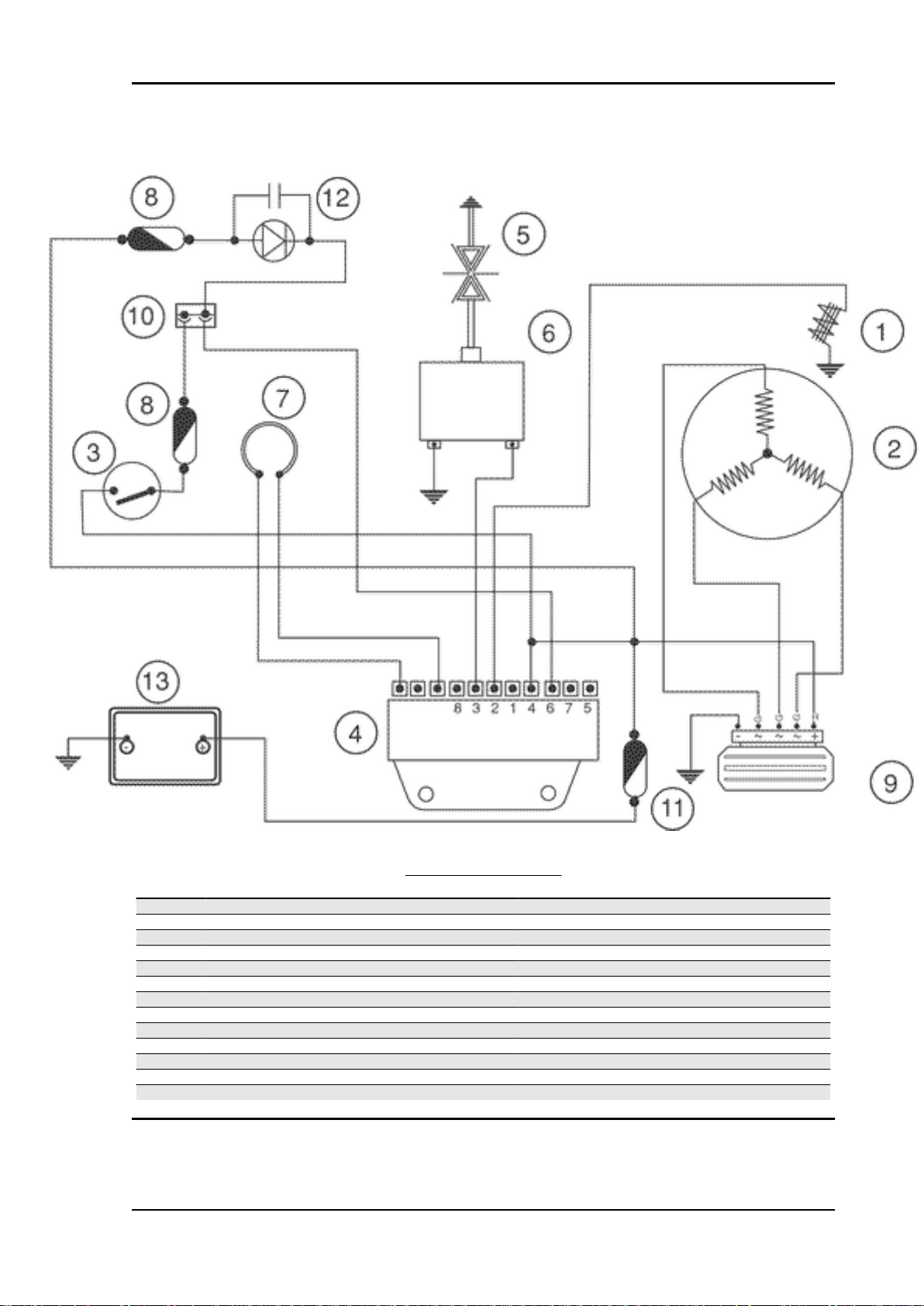
MSS X9 Evolution 250 Electrical system
ELECTRIC SYSTEM DIAGRAM
Specification
1 Front left direction indicator 1 bulb 12V - 10W
2 Outside temperature sensor
3 Combined brake stop button
4 Light switch
5 Indicators switch
6 Horn button
7 Emergency flashing button
8 "Reset" button
9 Front fuse holder box
10 Output for immobilizer diagnostic instrument
11 Fuse 7.5 A
12 Fuses 10A
13 Engine stop remote control switch
14 Headlight remote control switch
15 Connector fitting for PICS control unit
16 Diode
17 Connector fitting for PICS control unit
18 Analogue instrument unit
19 PICS display fitting
Desc./Quantity
ELE SYS - 53
Page 54

Electrical system MSS X9 Evolution 250
Specification Desc./Quantity
20 Digital instrument unit
21 Front headlight N° 2 position bulbs 12V - 5W, N° 1 dipped beam bulb
22 Wheel RPM sensor
23 Front brake stop button
24 Engine stop switch
25 Front right direction indicator N° 1 bulb 12V - 10W
26 Connector fitting for saddle opening device
27 Fitting for accessories
28 Anti-theft alarm fitting
29 Start up button
30 Key switch
31 Immobilizer aerial
32 Radiatore electric fan motor
33 Thermal switch for electric fan
34 Electronic ignition
35 Fuel level sender
36 HV coil
37 Thermistor
38 Oil pressure sensor
39 Pick - up
40 Automatic starter
41 Magneto flywheel
42 Rear right headlight N° 1 bulb 12V - 55W for position light, N° 1 bulb 12V -
43 License plate light bulb Type: ALL GLASS
44 Stop light N° 5 bulbs 12V-2.3W
45 Remote starter switch
46 Diodo
47 Battery 12V-12Ah
48 Fuse 15A
49 Fuse (Rear position light protection, number plate light,
front position light)
50 Fuse 10 A
51 Rear fuse holder box
52 Helmet compartment lamp bulb 12V-5W
53 Helmet compartment lighting button
54 Socket for users 12V - 180W max
55 Starter motor
56 Rear left headlight N° 1 bulb 12V - 55W for position light, N° 1 bulb 12V -
57 Voltage regulator
58 Saddle opening button
59 Saddle opening actuator
60 Stand switch
61 Horn
12V- 55W, N° 1 upper beam bulb 12V - 55W
10W for flashing light
Power: 12V - 5W
Quantity: 1
7.5A
10W for flashing light
Wiring colour chart:
B=White - Bl=Blue - G=Yellow - M=Brown - N=Black - BV=White-Green - GN=Yellow-Black - Gr=Grey
- Rs=Pink - R=Red - Vi=Purple - V=Green - VN=Green-Black - BN=White-Black - BBl=White-Blue -
GV=Yellow-Green - Ar=Orange - GrBl=Grey-Blue - GrN=Grey-Black - BR=White-Red - RN=Red-Black
- BlN=Blue-Black.
CAUTION
SHOULD ANY INTERVENTIONS TO THE ELECTRIC SYSTEM BE REQUIRED, MAKE SURE THAT
THE LEADS TO THE ELECTRONIC IGNITION DEVICE ARE PROPERLY CONNECTED ACCORDING TO POLARITY AND TO THE LEAD COLOURS.
Conceptual diagrams
ELE SYS - 54
Page 55
MSS X9 Evolution 250 Electrical system
Ignition
IGNITION SECTION
Specification
1 Pick - up
2 Magneto flywheel
3 Key switch contacts
4 Electronic controller
5 Spark plug
6 HV coil
7 Immobilizer aerial
8 Voltage regulator
9 Voltage regulator
10 Diagnostic tester outlet
11 Fuse 15A
12 Immobilizer LED
13 Battery 12V-12Ah
Desc./Quantity
ELE SYS - 55
Page 56

Electrical system MSS X9 Evolution 250
Headlights and automatic starter section
HEADLIGHTS AND AUTOMATIC STARTER SECTION
Specification
1 Electronic control unit
2 Voltage regulator
3 Battery 12V 12Ah
4 Automatic starter
5 Key switch contacts
6 Light switch
7 Light switch
8 Light remote control switch
9 Fuse (headlight remote control protection) 10 A
10 Helmet compartment lamp bulb 12V-5W
11 Fuse (upper beam protection) 10 A
12 Bulb for upper beams 12V-55W
13 Bulb for dipped beams 12V-55W
14 Fuse (Rear position light protection, number plate light,
front position light)
15 Bulbs N° 2 12v-3w front pos. Lights, n° 2 12v-5w rear pos.
Lights, n° 1 12v-5w number plate light
16 Fuse 15A
17 Socket for users 12V - 180W max
18 Helmet compartment lighting button
ELE SYS - 56
Desc./Quantity
7.5A
Page 57

MSS X9 Evolution 250 Electrical system
Battery recharge and starting
BATTERY RECHARGE AND START-UP
Specification
1 Key switch contacts
2 Magneto flywheel
3 Fuse 5A
4 Remote starter switch
5 Voltage regulator
6 Starter motor
7 Battery 12V-12Ah
8 Start-up enable and front stop button
9 Start-up enable and rear stop button
10 Digital instrument
11 Start up button
12 Fuse 15 A
13 Diode 1 A
14 Stop light N° 5 bulbs 12V-2.3W
15 Electronic ignition
16 Engine stop relay
17 Engine stop switch
18 Stand switch
19 Engine not enable indicator
Desc./Quantity
ELE SYS - 57
Page 58

Electrical system MSS X9 Evolution 250
Level indicators and enable signals section
LEVEL INDICATORS AND ENABLE SIGNALS
Specification
1 Digitsl instrument
2 Analogue instrument unit
3 Thermistor
4 Outside temperature sensor
5 Wheel RPM sensor
6 Fuel level sender
7 Oil pressure sensor
8 "Reset" button
9 Emergency button
10 Fuse 10 A
11 Key switch contacts
12 Radiatore electric fan motor
13 Thermal switch for electric fan
14 Magneto flywheel
15 Voltage regulator
16 Fuse 15A
ELE SYS - 58
Desc./Quantity
Page 59
MSS X9 Evolution 250 Electrical system
Specification Desc./Quantity
17 Battery 12V - 12Ah
Thermal switch
We inform you that a new thermal switch has been introduced starting with frame number
ZAPM2300003507739 (X9) ZAPM3620000003383 (X8) ZAPM2850000001025 (Beverly), in order to
prevent possible malfunctioning of the thermal switch.
Turn signal lights
FLASHING LIGHTS, HORN AND ACCESSORY FITTINGS
Specification
1 Digital instrument unit
2 Direction indicators N° 2 + 2 bulbs 12V-10W
3 Indicators switch
4 Fitting for accessories
5 Horn button
6 Horn
7 Fuse 10 A
8 Key switch contacts
9 Fuses 10A
Desc./Quantity
ELE SYS - 59
Page 60

Electrical system MSS X9 Evolution 250
Specification Desc./Quantity
10 Fuse 15 A
Checks and inspections
Immobiliser
The electric ignition system is fed with direct current and is protected by an antitheft immobilizer
integrated to the control unit.
The ignition system consists of:
- electronic control unit
- immobilizer aerial
- master and service keys with built-in transponder
- HV coil
- diagnosis LED
-The diagnostic LED also works as a deterring
blinker. This function is activated every time the
key switch is turned to "OFF" and it remains active
48 hours so as not to damage the battery charging
process.
When the key switch is turned to "ON", this blinking
function is deactivated. A flash then confirms the
system has switched to "ON".
The duration of the flash depends on the electronic
control unit program (see figure).
If the led turns off and remains so when switching
to "ON", it is necessary to check if there is battery
voltage in the electric control unit.
Connect the immobilizer tester to the diagnosis
socket (see ET4 125 manual) located below the
spark plug inspection port.
If the serial LED remains off, proceed to check the
control unit supply as follows:
- Disconnect the control unit connector and check
if:
- There is battery voltage between terminal No. 4
(Red/Black) and the ground lead.
ELE SYS - 60
Page 61

MSS X9 Evolution 250 Electrical system
- There is battery voltage between the terminal No.
4 (Red/Black) and terminal No. 8 (Negative) as
shown in the figure.
If no voltage is detected, check the wiring to the
battery positive lead and see if the 15A fuse is in
good conditions (see the start-up diagram)
- There is battery voltage between terminals No. 5
and No. 8 with the key switch set to "ON", the side
stand retracted and the emergency switch set to
"RUN".
If no faults are found, replace the control unit; otherwise check the wiring and the following components:
- Engine stop remote control;
- Emergency cut-off switch;
- Side stand contacts;
- Key switch contacts.
Virgin circuit
If the ignition system has not been programmed,
the engine can be started but it will run limited to
2000 rpm. When trying to accelerate, some evident loss of power may be felt.
Program the system with the MASTER (Brown)
and SERVICE (Black) keys as follows:
- Insert the MASTER key, turn it to "ON" and keep
it in that position for 2 seconds (limit values: 1 ÷ 3
seconds).
- Alternately insert all the available black keys and
turn each one of them to "ON" for 2 seconds.
- Insert the MASTER key again and turn it to "ON"
for 2 seconds.
The maximum time to change keys is 10 seconds.
A maximum of 7 (Black) service keys can be programmed at one time.
ELE SYS - 61
Page 62
Electrical system MSS X9 Evolution 250
Sequence and times must be strictly observed or
it will be necessary to repeat the procedure from
the start.
Once the control unit has been programmed, the
control unit is inseparably matched with the MASTER key transponder.
This matching allows programming further service
keys in case of loss, replacement, etc. Each new
time new data is programmed the previously stored one is deleted.
If a service key setting is lost, it is essential to
carefully check the efficiency of the high voltage
system:
Shielded cap resistance ~ 5000 Ω.
In any case it is advisable to use resistive spark
plugs.
Diagnostic codes
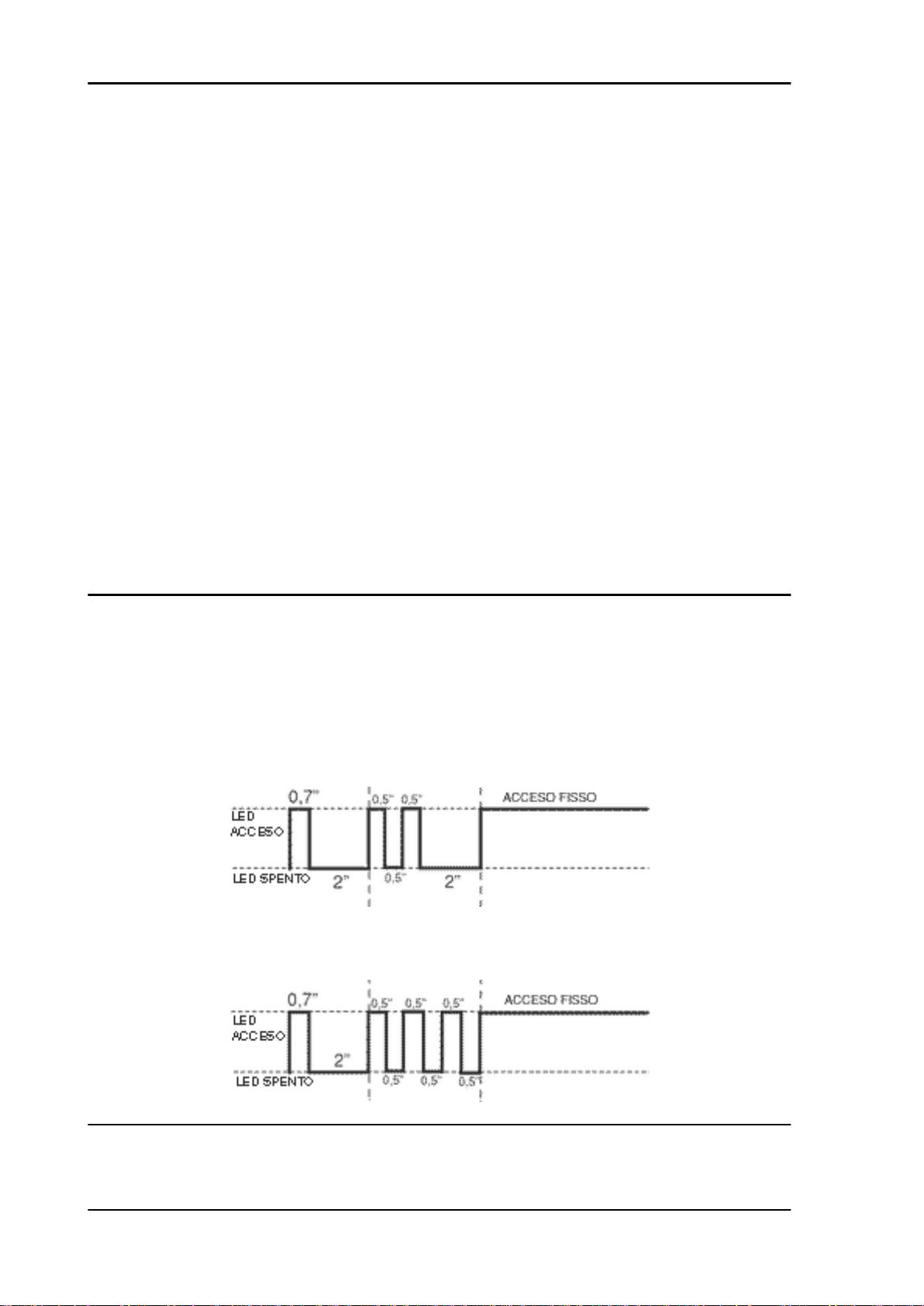
The flash indicating the switching to "ON" can be followed by a phase of programmed failure warnings.
That is, the led is off for 2 seconds, and then diagnosis codes are transmitted with 0.5-second flashes.
After the failure code indication, a steadily on LED signals that ignition is disabled; see the table:
2-FLASH CODE - Example with programmed control unit, no transponder and/or malfunctioning aerial.
Ignition disabled-Vehicle immobilised
3-FLASH CODE - Example with programmed control unit, aerial working properly and unknown trans-
ponder code. Ignition disabled-Vehicle immobilised
Diagnostic code - 2 flashes
Diagnosis code: 2-flashes
ELE SYS - 62
Page 63

MSS X9 Evolution 250 Electrical system
When the 2-flash code is detected, carry out the following checks:
- Check if the failure continues after changing key (MASTER key included). If the failure persists with
any key, disconnect the aerial connector from the control unit and check the aerial continuity with the
020331Y multimeter.
If non-conforming values are measured, replace the aerial.
If no failures are found in the aerial, replace the control unit.
CAUTION
BEFORE PROGRAMMING THE NEW ELECTRONIC CONTROL UNIT CHECK THAT NO FAILURE
CODE IS INDICATED. THIS IS NECESSARY TO AVOID SPOILING A NEW CONTROL UNIT
Electric characteristic
immobilizer aerial
~ 7 ÷ 9 Ohm
Diagnostic code - 3 flashes
If the 3-flash code is detected, check if the failure
occurs when the MASTER key in inserted into the
key switch.
- If the failure disappears when the MASTER key
is used, proceed to encode the service keys
(Black).
- If the failure persists, it means that the MASTER
key and the control unit are not linked; in this case,
replace the control unit and then encode the keys.
The immobilizer system is efficient when, after
switching over to "ON", only a 0.7-second flash is
detected (see diagram).
In this case, the engine can be started.
Example with programmed control unit, transponder, programmed key and aerial working properly.
Ignition is enabled (regular conditions of use)
Ignition circuit
Once the immobilizer system is enabled, the HV coil and the signals from the Pick-Up will produce a
spark in the spark plug.
The battery provides the basic power supply. The system is adjusted so that the start-up system immediately detects an eventual battery voltage drop, but this is practically irrelevant for the ignition
system.
ELE SYS - 63
Page 64
Electrical system MSS X9 Evolution 250
The Pick-Up is connected to the control unit by a single cable; then, for the ground circuit, the control
unit is connected to the Pick-Up by the chassis and the engine ground lead.
To avoid disturbances in the ignition system during start-up, it is very important that the engine-chassis
ground connection bonding is efficient.
No spark plug
Once the lack of power to the spark plug has been
detected and the LED indicates it can be ignited,
follow this procedure:
- Pick-Up check.
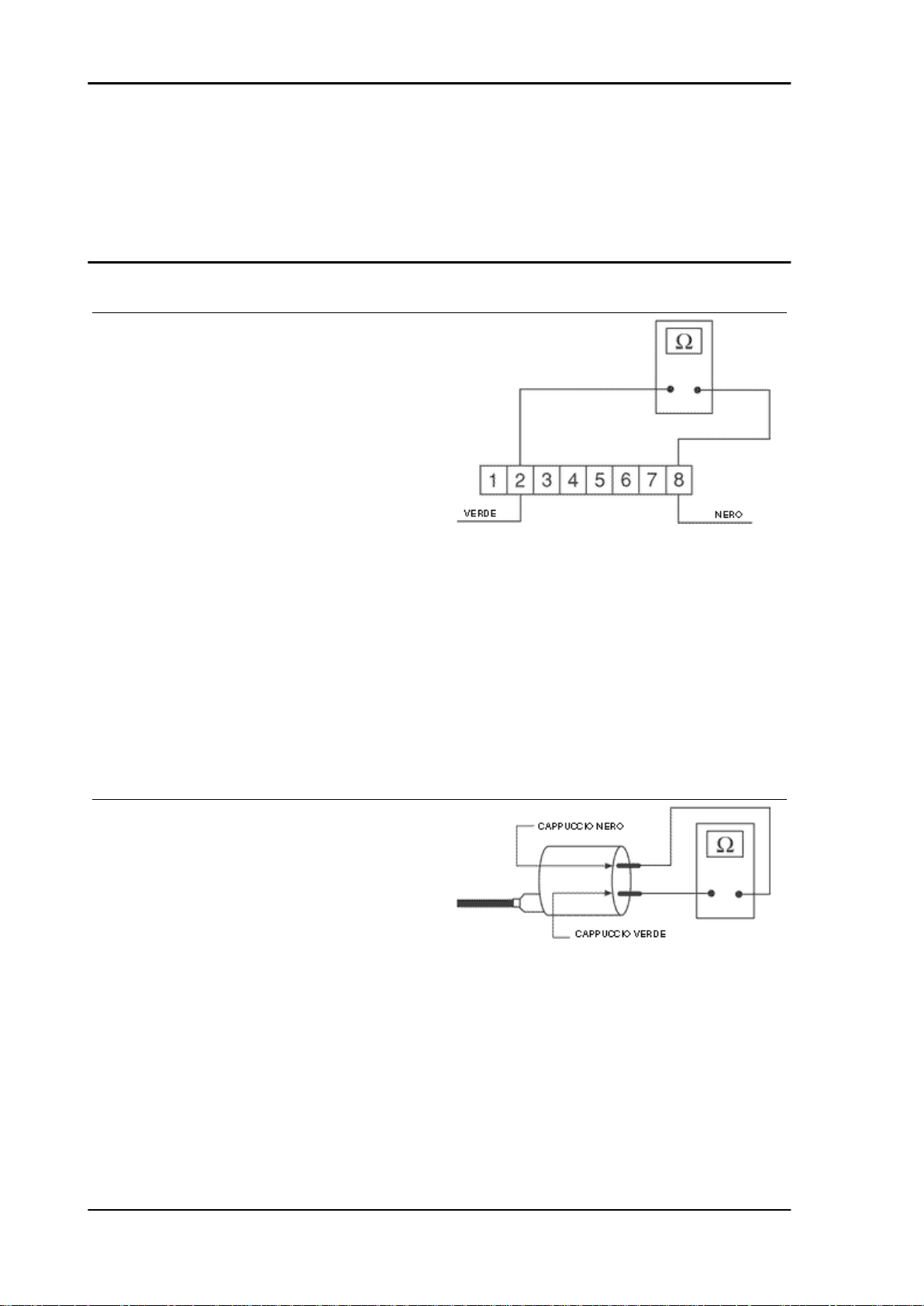
Disconnect the control unit connector and check
that the cable between terminal No. 2 (Green) and
terminal No. 8 (Black) is not interrupted. Check the
Pick-Up and its power line:
Electric characteristic
Pick-up resistance value
Pick-up resistance value: 105 ÷ 124 Ohm
If a break in the circuit is found, check again the flywheel and the engine ground connectors (see engine
manual). If non-conforming values are detected, replace the Pick-Up, otherwise check the cable harness and the connections. In case conforming values are measured and the wiring and connections
check is OK, try replacing the control unit (without programming) and make sure the failure has been
solved by checking sparks are produced in the spark plug; only then program the control unit. If no
sparks are produced with the new control unit, proceed as follows.
- HV primary coil check
Disconnect the two connectors on the HV coil and
check continuity (see figure). If non-conforming
values are measured, replace the HV coil. If conforming values are measured, check the cable
harness taking into account that the HV coil positive wire has a branch that comes into the digital
instrument panel (violet cable). Therefore, make
sure this line is in perfect conditions. If failures are
detected, check the HV coil secondary.
Electric characteristic
High voltage coil primary resistance value
High voltage coil primary resistance value: 0.4 ÷
0.5 Ohm
ELE SYS - 64
Page 65

MSS X9 Evolution 250 Electrical system
HV coil secondary check
Disconnect the spark plug cap from the HV cable and measure the resistance between the HV cable
terminal and the HV coil negative terminal (see figure). If non-conforming values are measured, replace
the HV coil. To carry out a more complete diagnosis, check the peak voltage with the multimeter adaptor.
Electric characteristic
High voltage coil secondary resistance value
High voltage coil secondary resistance value: ~ 3000 ± 300 Ohm
- Pick-Up.
- Disconnect the control unit connector and connect the positive terminal to connector No. 2 and
the negative terminal to connector No. 8 (see figure).
Use the start-up system to run the engine and
measure the voltage produced by the Pick-Up.
Replace Pick-Up if non-conforming values are
measured.
Electric characteristic
Pick-Up voltage value
Pick-Up voltage value: > 2 Volt
- HV coil
With the control unit and HV coil connected, measure the voltage of the coil primary during the startup test with the voltage peak adaptor and connecting the positive terminal to the ground one and
the negative to the coil positive connector.
If non-conforming values are measured, replace
the control unit.
N.B.
THE PLASTIC CAP OF THE POSITIVE TERMINAL ON THE
HV COIL PRIMARY IS BLACK AND THE NEGATIVE TERMINAL ONE IS GREEN.
Electric characteristic
ELE SYS - 65
Page 66
Electrical system MSS X9 Evolution 250
High voltage coil voltage value
High voltage coil voltage value: > 100 Volt
Stator check
Disconnect the connector from the voltage regulator and check there is continuity between any yellow
cable and the other two cables.
Electric characteristic
Ohm value:
0.7 ÷ 0.9 Ohm
Also check that all yellow cables are insulated from
the ground connection.
If non-conforming values are detected, repeat the
checks directly to the stator. In case of further repetitions of incorrect values replace the stator or
repair the wiring.
- Using a tester, check the continuity between connection 4-3, 4-1 and 3-1.
- Check the earth insulation on the three stator
phases 4-earth, 3-earth and 1-earth.
Indicative resistance of each phase: 0.7 ÷ 0.9 Ω
Pick-Up Check
- Check that there is a resistance of about 105 ÷
124 Ω at 20°C between connection 2 and earth.
- If you read values other those stated, replace the
defective parts.
N.B.
ELE SYS - 66
Page 67
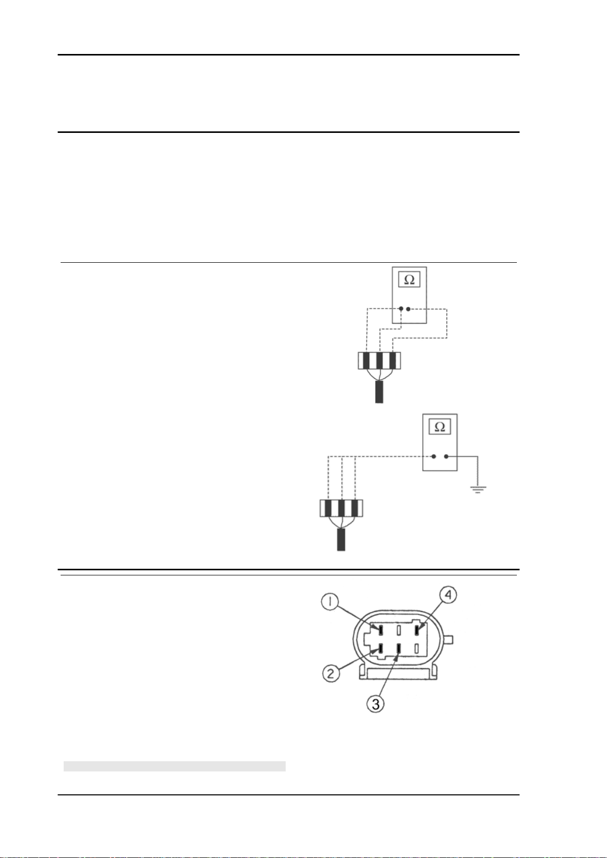
MSS X9 Evolution 250 Electrical system
VALUES ARE STATED AT AMBIENT TEMPERATURE. A
CHECK WITH THE STATOR AT OPERATING TEMPERATURE MAY RESULT IN VALUES HIGHER THAN THOSE
STATED.
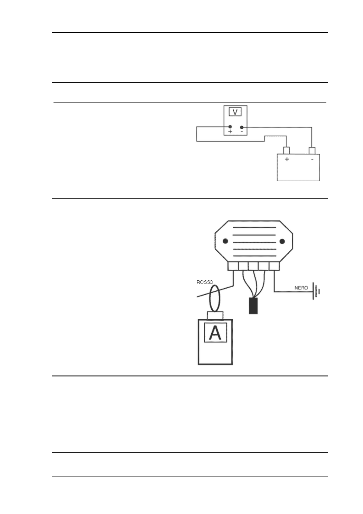
Voltage regulator check
With a perfectly charged battery and lights off,
measure voltage at the battery poles with a high
running engine.
The voltage should not exceed 15.2 Volt.
In case higher voltages are detected, replace the
regulator.
In case of voltage values lower than 14 Volt, check
the stator and the corresponding cable harness.
Recharge system voltage check
Connect an ammeter induction clamp to the voltage regulator positive terminal, measure the battery voltage and turning on the vehicles lights with
engine off, wait for the voltage to set at about 12
V. Start the engine and measure the current generated by the system with lights on and a high
running engine.
In case the generated current value is lower than
10A, repeat the test using a new regulator and/
stator alternatively.
The recharge system is provided with a three phase generator with permanent magneto flywheel. The
generator is directly connected to the voltage regulator. In turn, the latter is directly connected to earth
and to the battery positive passing through the 15A safety fuse. This system therefore requires no
connection to the key switch. The three phase generator allows a considerable recharge power and at
lower rpm it enables a good combination of delivered power and idle steadiness. For this reason, idle
speed must be adjusted according to the prescriptions.
ELE SYS - 67
Page 68

Electrical system MSS X9 Evolution 250
Choke Inspection
Refer to the engine section to check the resistance
and operating conditions of the component. As regards voltage supply, keep the connector connected to the system and check that the two terminals
receive battery voltage when the engine is on (see
figure).
If voltage is detected, replace the automatic starter
as it is surely failing.
If no voltage is detected, connect the multimeter
negative terminal to the earth terminal and the
positive terminal to the automatic starter orange
cable; with the key switch set to «ON» check
whether there is battery voltage; if there is no voltage, check the wiring connections to the key
switch and that the 15A fuse works properly.
If there is voltage, check again the ignition control
unit connector. After disconnecting the starter,
start the engine and keep it at idle speed. Check if
there is voltage when the multimeter positive
probe is connected to the terminal No. 5 (Sky blue)
and the negative one to the terminal No. 7 (Black/
White) (see figure).
Replace the control unit if there is no voltage; otherwise, check the wiring connections between the
starter and the control unit.
Lights list
List of lamps
Electric characteristic
Number plate lights
12V-5W
Trunk lights
12V-5W
Instrument panel lights
12V-2W x 5
Rear direction indicator lights
12V-10W x 2
ELE SYS - 68
Page 69

MSS X9 Evolution 250 Electrical system
Stop lights
12V-2,3W x 5
Rear position lights
12V-5W x 2
Front turn indicator bulbs
Front turn indicator bulbs 12V-10W x 2
Front position lights
12V-5W x 2
Upper beam light
12V-55W
Dipped beam light
12V-55W
Fuses
The electric system is equipped with:
- four protective fuses «A» into the helmet compartment,
- four fuses «B» for the system circuitry safety, located inside the port in the rear left side of the
shield.
The tables shows the features of the fuses on the
vehicle.
CAUTION
BEFORE REPLACING A BLOWN FUSE, FIND AND SOLVE
THE FAILURE THAT CAUSED IT TO BLOW. NEVER TRY
TO REPLACE THE FUSE USING ANY OTHER MATERIAL
(A PIECE OF ELECTRICAL WIRE, FOR EXAMPLE) OR A
FUSE OF A DIFFERENT RATING THAN THAT SPECIFIED.
Electric characteristic
Light indicator on digital instrument panel,
front and rear side/taillights
7.5 A
Digital instrument panel, diagnostic led indicator on analogue instrument.
10 A
Brake lights, vehicle start-up enabling signal
7.5 A
Horn, upper beam and indicator on "Passing"
function
10 A
ELE SYS - 69
Page 70
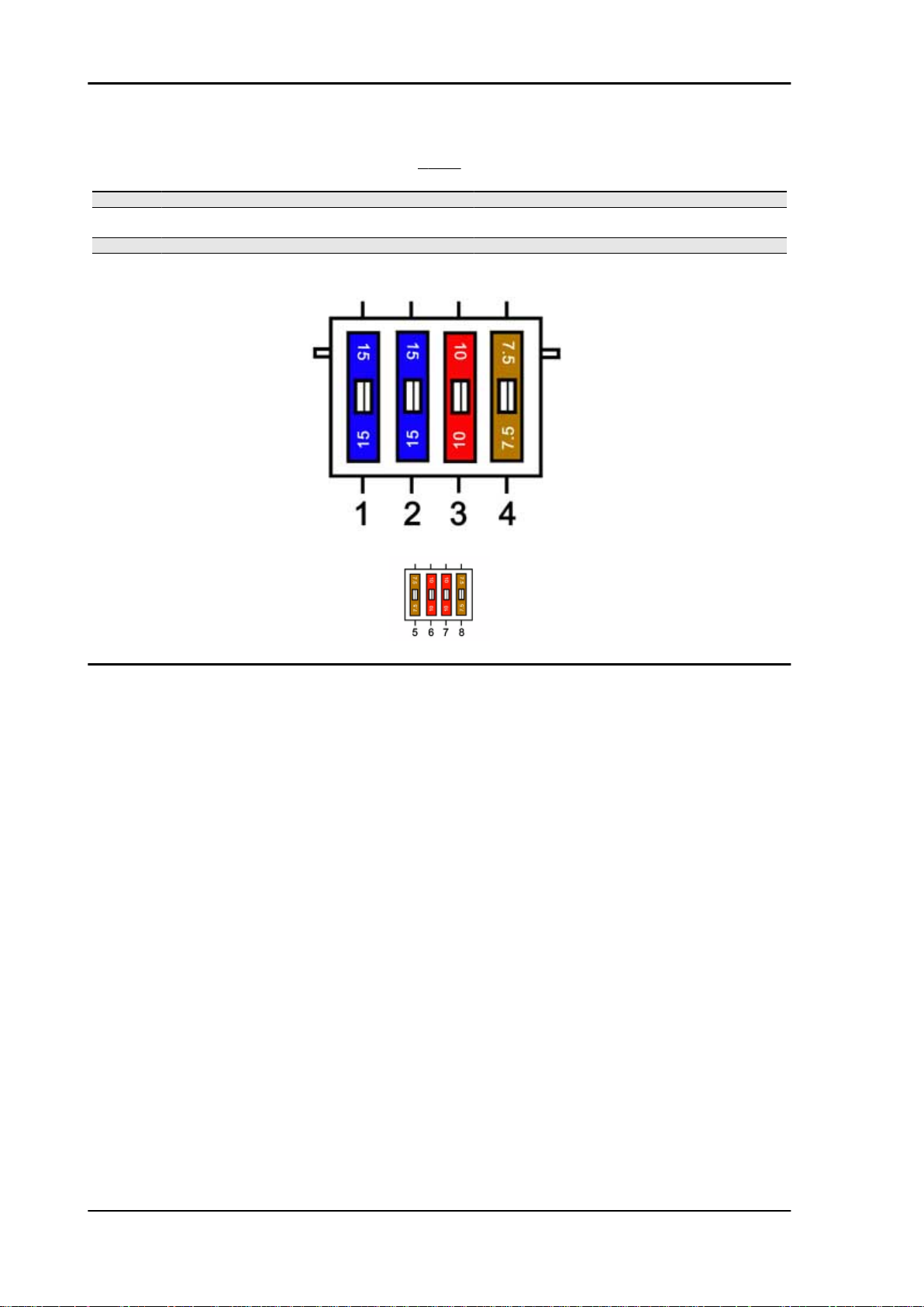
Electrical system MSS X9 Evolution 250
FUSES
Specification Desc./Quantity
1 Helmet compartment, 12-V socket 15 A
2 General (battery recharge, lights, radiator electric fan,
electronic control unit).
3 Headlight (upper and dipped beams). 10 A
4 Digital instrument panel 7.5 A
15 A
Dashboard
Vehicle X9 is provided with an instrument panel divided into 2 sections: the analogue section is fixed
into the cap while the digital section is integral to the handlebar.
The analogue section includes:
- Tachometer with dual scale (MPH/KMH) controlled by the fifth wheel;
- RPM counter controlled by the signal sent by the H.V. coil.
- Fuel level indicator controlled by a resistive sensor (into the tank)
- Cooling fluid temperature indicator controlled by a resistive sensor (on the head)
These instruments are electrical and managed by stepping motors.
The instrument panel digital section is completed by a liquid crystal display and 4 control buttons.
The display has 3 icons:
- Oil
- Service
- Belt
- The «Oil» icon flashes when 1,000 Km are reached, after that every 3,000 Km.
- The «Service» icon flashes when 1,000 Km or 1 year is reached. After that, it flashes every 6,000 km
or 1 year.
- The «Belt» icon warns the user of the need of replacing the driving belt. This occurs every 12,000 Km
ELE SYS - 70
Page 71

MSS X9 Evolution 250 Electrical system
A: Fitting for indicator light *
B: Fitting for indicator light *
C: Fitting for indicator light *
D: Engine disabled
E: Oil pressure
F: Fuel reserve
G: Position and dipped beam lights: green coloured
H: Upper beams on
I: Left direction indicator
L: Emergency lights (four direction indicators)
M: Right direction indicator
* The DGT instrument does not include the LEDs for the indicator light fittings
The fuel reserve, direction indicators and emergency flashing functions are activated by the instrument
electronics. For example, the fuel reserve indicator light only turns on when the reserve indication coming from the engine lasts at least 13.5 seconds. This prevents the intermitting turning on of the reserve
light indicator.
- The intermitting function is built in the instrument electronics: this allows operating the emergency
lights with switch in position «OFF» and control switch off. The control switch is only active when the
instrument panel is on.
To ensure safety while riding, the «direction indicators control» function is connected to the odometer.
If the indicator is left on, it automatically stops after 1 kilometre travelled.
- The «engine disabled» indicator is activated by the side stand switch and by the emergency switch
on the right side of the handlebar.
- The LCD display gives a 5 digit indication for the total kilometres covered by the vehicle. It can be
expressed in kilometres or in miles: of course, this indication cannot be reset. To select the indication,
press "Trip" and «M» at the same time, then tirn the key switch to «ON»; keep these 2 buttons
pressed for more than 3" to display «SET» on the display, then the display switches from miles
to kilometres, or vice versa.
After servicing by the authorised workshop, the
icon message must be reset by the "Reset" button
located in the front side of the vehicle under the
fairing.
The "Reset" button allows resetting the kilometres
covered and, in the case of "Service", also the year
count. This count remains active even if the battery
is disconnected for a short time.
ELE SYS - 71
Page 72

Electrical system MSS X9 Evolution 250
To reset one of the icons, press the «Reset»
button for less than a second, then on the icon
before that to be reset press «Reset» for at
least 3" so as to display:
- The selectionj of the desired icon through the
relevant solid light.
- The flashing of this light confirms the reset.
- For example, to reset the «Service» icon, go to
«Oil» and press the «Reset» button for at least 3".
To reset «Oil», repeat the above procedure going
to «Belt».
This procedure must be repeated since the selection of the icon and its reset are operations to be
made at the same time (it is not possible to view
the desired function and reset by two different button pressures since in this way the next icon would
be reset).
Data check function
Date and check function
Date should be adjusted out when delivering the vehicle to the customer. This is because the clock
activation starts the year count for the "Service" function. If the clock has been previously activated,
reset the "Oil", "Service" and "Belt" functions. The calendar is programmed from 2000 to 2050. For date
and time adjustment act on the "Clock" and "Set" buttons.
To guarantee vehicle safety, each time the key switch is set to "ON", there is an automatic checking of
all the indicators on the digital section.
The digital section provides also a functional checking of the 4 analogue instruments and of the turn
indicator control. To activate this checking, press and holed the "Clock" and "Set" buttons simultaneously and then set the key switch to "ON". Within 4 seconds max, the software version is displayed, the
gauges go to the end of scale and the turn indicators light up.
At the end of the operation above, the normal warning light bulbs check is carried out.
Sealed battery
If the vehicle is provided with a sealed battery, the only maintenance required is the check of its charge
and recharging, if necessary.
These operations should be carried out before delivering the vehicle, and on a six-month basis while
the vehicle is stored in open circuit.
ELE SYS - 72
Page 73

MSS X9 Evolution 250 Electrical system
Besides, upon pre-delivery it is therefore necessary to check the battery charge and recharge it, if
required, before storing the vehicle and, afterwards, every six months.
INSTRUCTIONS FOR THE BATTERY REFRESH AFTER OPEN-CIRCUIT STORAGE
1) Voltage check
Before installing the battery on the vehicle, check the open circuit voltage with a regular tester.
- If voltage exceeds 12.60 V, the battery can be installed without any renewal recharge.
- If voltage is below 12.60 V, a renewal recharge is required as explained in 2).
2) Constant voltage battery charge mode
- Constant voltage charge equal to 14.40 ÷ 14.70V
- Initial charge voltage equal to 0.3 ÷ 0.5 for Nominal capacity
- Charge time:
10 to 12 h recommended
Minimum 6 h
Maximum 24 h
3) Constant current battery charge mode
- Charge current equal to 1/10 of the nominal capacity of the battery
- Charge time: 5 h
CAUTION
NEVER USE FUSES WITH A CAPACITY HIGHER THAN THE RECOMMENDED CAPACITY. USING
A FUSE OF UNSUITABLE RATING MAY SERIOUSLY DAMAGE THE VEHICLE OR EVEN CAUSE
A FIRE.
CHARGE THE BATTERY BEFORE USE TO ENSURE OPTIMUM PERFORMANCE. INADEQUATE
CHARGING OF THE BATTERY WITH A LOW ELECTROLYTE LEVEL BEFORE IT IS FIRST USED
SHORTENS THE LIFE OF THE BATTERY.
IF THE VEHICLE IS NOT USED FOR SOME TIME (1 MONTH OR MORE) THE BATTERY NEEDS
TO BE RECHARGED PERIODICALLY. THE BATTERY RUNS DOWN COMPLETELY IN THE
COURSE OF THREE MONTHS. IF IT IS NECESSARY TO REFIT THE BATTERY IN THE VEHICLE,
BE CAREFUL NOT TO REVERSE THE CONNECTIONS TAKING INTO ACCOUNT THAT THE
GROUND WIRE (BLACK) MARKED(-) MUST BE CONNECTED TO THE - NEGATIVE TERMINAL
WHILE THE OTHER TWO RED WIRES MARKED (+) MUST BE CONNECTED TO THE TERMINAL
MARKED WITH THE +POSITIVE SIGN
WARNING
WHEN THE BATTERY IS REALLY FLAT (WELL BELOW 12.6V) IT MIGHT OCCUR THAT 5 HOURS
OF RECHARGING ARE NOT ENOUGH TO ACHIEVE OPTIMAL PERFORMANCE.
GIVEN THESE CONDITIONS IT IS HOWEVER ESSENTIAL NOT TO EXCEED 8 HOURS OF CONTINUOUS RECHARGING SO AS NOT TO DAMAGE THE BATTERY ITSELF.
Dry-charge battery
- Remove the battery ventilation duct closing cap and remove the caps from the single elements.
- Fill the battery with electrolyte having a density of 1.270+/-0.01 Kg/l (corresponding to 31+/-1 Bé) with
minimum ambient temperature of 15 °C, up to the top level indicated on the single block.
- Slightly tilt the battery to remove any air bubbles formed during the filling.
- Place the caps on the filling holes of the single elements without tightening them and let the battery
stand. During this phase, the battery undergoes a gasification phenomenon and temperature rises.
ELE SYS - 73
Page 74

Electrical system MSS X9 Evolution 250
- Let it stand until ambient temperature is reached again (this phase may require up to 60 minutes).
- Slightly tilt the battery to favour the removal of any air bubbles, then restore the levels using the same
electrolyte.
Within 24 hours, refill as follows:
- Connect the battery charger terminals according to the right polarity;
- Using the battery charger dwg. 020333Y and/or dwg. 020334Y, select the battery capacity;
- If the battery charger is not available, charge the battery with a constant current of 1/10 of the rated
capacity (for example for a battery with rated capacity of 9Ah, the charge current must be 0.9-1.0A), for
approx. 4-6 hours.
- Let the battery stand with open circuit for approx. 4-6 hours, then check the voltage using a normal
tester.
- If the open circuit voltage is more or equal to 12.6V, the battery charge is good. Slightly tilt the battery
to eliminate any air bubbles formed while recharging.
- Check the electrolyte level again, restore if required up to the tol reference using distilled water, tighten
the caps of the single elements and install it on the vehicle.
- If lower voltages are detected, recharge the battery for 4-6 hours more as described above.
N.B.
BATTERIES STORED FOR A LONG TIME CAN REQUIRE LONGER TIMES. BATTERY CHARGERS
DWG. 020333Y AND DWG. 020334Y HAVE AN AUTOMATIC PROTECTION THAT STOPS THE
RECHARGE AFTER 12 HOURS TO PREVENT OVERHEATING THE BATTERY. IN THIS CASE, THE
TURNING ON OF THE GREEN LED DOES NOT INDICATE THE END OF THE CHARGE BUT THE
START OF THE SAFETY SYSTEM.
N.B.
THIS IS THE LAST TIME THAT ELECTROLYTE CAN BE ADDED. FUTURE TOP UPS MUST BE
MADE USING ONLY DISTILLED WATER
N.B.
WITH BATTERY CHARGER DWG. 020334Y YOU CAN CHECK THE BATTERY CHARGE LEVEL
BY THE FUNCTION CHECK. THE VALUE SHOWN ON THE DISPLAY MUST BE HIGHER THAN
THAT INDICATED IN THE TABLE; IF NOT, RECHARGE AS DESCRIBED ABOVE.
Connectors
ELE SYS - 74
Page 75
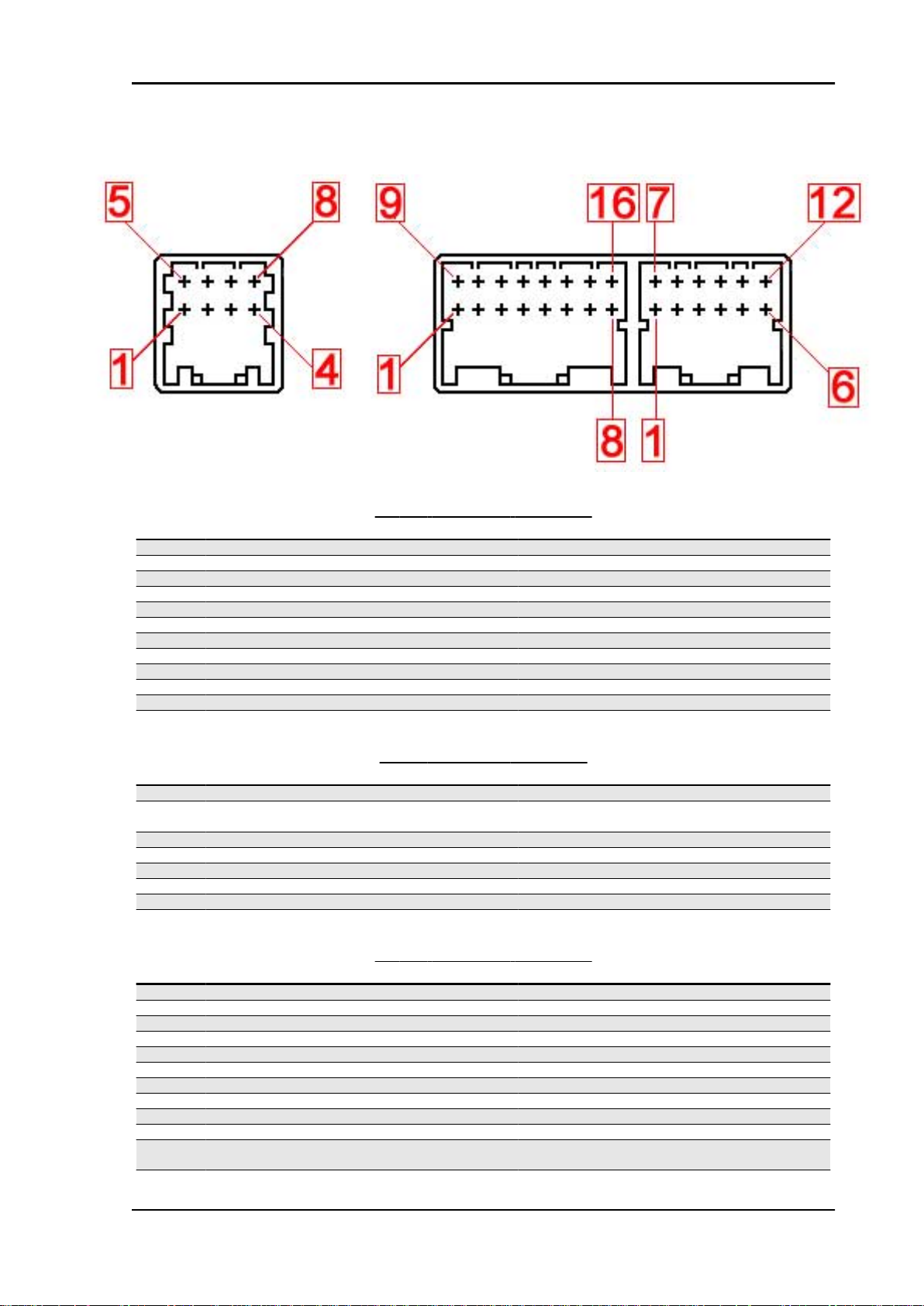
MSS X9 Evolution 250 Electrical system
Dashboard
12-WAY INSTRUMENT CONNECTOR
Specification Desc./Quantity
1 BATTERY POSITIVE LEAD (+30) BATTERY POSITIVE LEAD (+30)
2 SPEEDOMETER SENSOR POWER SUPPLY SPEEDOMETER SENSOR POWER SUPPLY
3 SPEEDOMETER SENSOR BACK TO GROUND SPEEDOMETER SENSOR BACK TO GROUND
4 REVOLUTION SENSOR INPUT REVOLUTION SENSOR INPUT
5 BATTERY POSITIVE LEAD (+30) BATTERY POSITIVE LEAD (+30)
6 ANTITHEFT DEVICE LED ANTITHEFT DEVICE LED
7 KEY POSITIVE TERMINAL (+15) KEY POSITIVE TERMINAL (+15)
8 SPEEDOMETER SENSOR INPUT SPEEDOMETER SENSOR INPUT
9 GROUND GROUND
10 AIR TEMPERATURE SENSOR BACK TO GROUND AIR TEMPERATURE SENSOR BACK TO GROUND
11 EMERGENCY LIGHT BUTTON (HAZARD) INPUT EMERGENCY LIGHT BUTTON (HAZARD) INPUT
12 LIGHTS ON INPUT LIGHTS ON INPUT
8-WAY INSTRUMENT CONNECTOR
Specification
1 GROUND ANALOGUE CHART GROUND ANALOGUE CHART
2 BATTERY POSITIVE LEAD (+30) FOR ANALOGUE
CARD
3 ANALOGUE CARD SERIAL CLOCK OUTPUT ANALOGUE CARD SERIAL CLOCK OUTPUT
4 ANTITHEFT DEVICE LED OUTPUT ANTITHEFT DEVICE LED OUTPUT
5 ANALOGUE CARD SERIAL DATE OUTPUT ANALOGUE CARD SERIAL DATE OUTPUT
6 LIGHTS ON OUTPUT LIGHTS ON OUTPUT
7 (Not connected)
8 (Not connected)
BATTERY POSITIVE LEAD (+30) FOR ANALOGUE
Desc./Quantity
CHART
16-WAY INSTRUMENT CONNECTOR
Specification
1 GENERAL USE WARNING LIGHT INPUT GENERAL USE WARNING LIGHT INPUT
2 ABS WARNING LIGHT INPUT (NOT CONNECTED) ABS WARNING LIGHT INPUT (NOT CONNECTED)
3 STOP LIGHT NOT WORKING OUTPUT STOP LIGHT NOT WORKING OUTPUT
4 RIGHT TURN INDICATOR OUTPUT RIGHT TURN INDICATOR OUTPUT
5 RIGHT TURN INDICATOR BUTTON INPUT RIGHT TURN INDICATOR BUTTON INPUT
6 LEFT TURN INDICATOR BUTTON INPUT LEFT TURN INDICATOR BUTTON INPUT
7 HIGH-BEAM WARNING LIGHT INPUT HIGH-BEAM WARNING LIGHT INPUT
8 AIR TEMPERATURE SENSOR INPUT AIR TEMPERATURE SENSOR INPUT
9 ENGINE UNABLE TO START WARNING LIGHT INPUT ENGINE UNABLE TO START WARNING LIGHT INPUT
10 OIL PRESSURE WARNING LIGHT INPUT OIL PRESSURE WARNING LIGHT INPUT
11 STOP LIGHT NOT WORKING WARNING LIGHT IN-
PUT
12 LEFT TURN INDICATOR OUTPUT LEFT TURN INDICATOR OUTPUT
STOP LIGHT NOT WORKING WARNING LIGHT IN-
Desc./Quantity
PUT
ELE SYS - 75
Page 76

Electrical system MSS X9 Evolution 250
Specification Desc./Quantity
13 TURN INDICATOR OFF SWITCH INPUT TURN INDICATOR OFF SWITCH INPUT
14 RESET SERVICE MANAGEMENT BUTTON INPUT RESET SERVICE MANAGEMENT BUTTON INPUT
15 WATER TEMPERATURE SENSOR INPUT WATER TEMPERATURE SENSOR INPUT
16 FUEL LEVEL SENSOR INPUT FUEL LEVEL SENSOR INPUT
ELE SYS - 76
Page 77

INDEX OF TOPICS
ENGINE FROM VEHICLE ENG VE
Page 78

Engine from vehicle MSS X9 Evolution 250
Removal of the engine from the vehicle
- Remove the saddle and the side covers,
- Drain engine oil and coolant,
- Disconnect the battery,
- Remove the muffler assembly,
- Remove the rear wheel,
- Remove the throttle grip transmission,
- Disconnect the electrical devices,
- Disconnect the hoses (petrol-oil-vacuum-operated cock control).
WARNING
Wear safety goggles when using hitting tools.
WARNING
BE VERY CAREFUL WHEN HANDLING FUEL.
CAUTION
WHEN INSTALLING THE BATTERY, ATTACH THE POSITIVE LEAD FIRST AND THEN THE NEGATIVE LEAD.
Silencer fixing
Please take note that, starting from chassis serial number ZAPM2300004503144, the three M8 x 50
silencer bracket fixing screws have been replaced by three M8 x 60 flanged head screws in order to
strengthen this fixing.
- Remove the nut shown in the figure, then take
out the pin.
ENG VE - 78
Page 79

MSS X9 Evolution 250 Engine from vehicle
- Remove the nut shown in the figure, then take
out the pin. The engine is now free.
- Carry out the removal operations but in reverse order, observing the prescribed tightening torques.
Locking torques (N*m)
Lower shock absorber clamp 33 ÷ 41 Engine-swinging arm bolt 33 ÷ 41
ENG VE - 79
Page 80

INDEX OF TOPICS
ENGINE ENG
Page 81
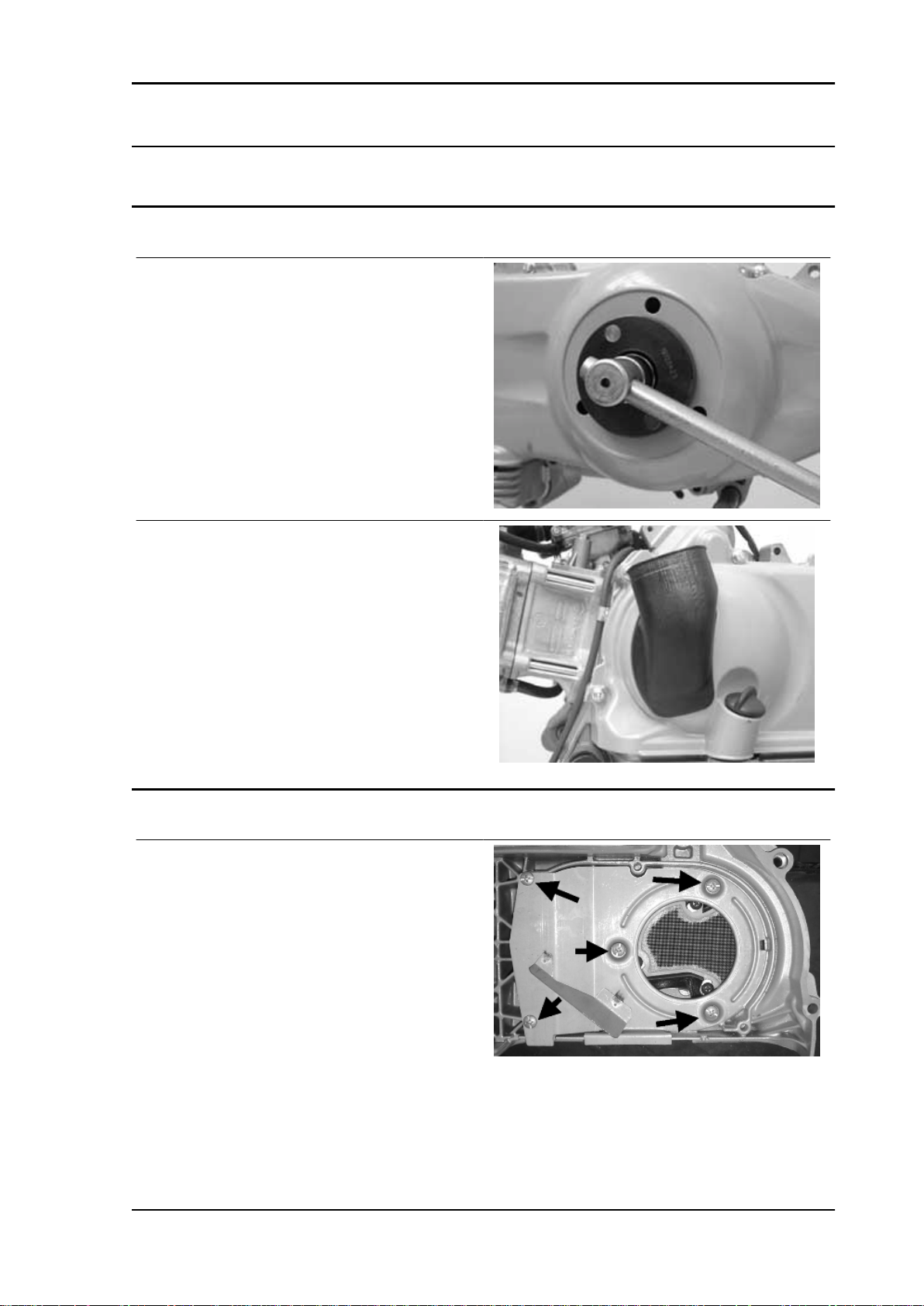
MSS X9 Evolution 250 Engine
Automatic transmission
Transmission cover
- To remove the transmission cover it is necessary
to remove the plastic cover first, by inserting a
screwdriver in the slotted holes. Using the clutch
bell lock wrench shown in the figure, remove the
driven pulley shaft locking nut and washer.
Specific tooling
020423Y driven pulley lock wrench
- Remove the cap/dipstick from the engine oil filling
hole.
- Remove the ten screws.
- Remove the transmission cover.
If this operation is carried out directly on the vehicle, remove the cooling air supply coupling of the
transmission housing.
Air duct
- Remove the five screws on two different levels
as well as the small casing.
ENG - 81
Page 82

Engine MSS X9 Evolution 250
- To remove the intake throat on the transmission
cover, just remove the 3 fixing screws indicated in
the figure.
Removing the driven pulley shaft bearing
- Remove the clip from the inside of the cover.
- Remove the bearing from the crankcase by
means of:
Specific tooling
020376Y Adaptor handle
020375Y Adaptor 28 x 30 mm
020412Y 15 mm guide
Refitting the driven pulley shaft bearing
- Slightly heat the crankcase from the inside so as
not to damage the painted surface.
- Insert the bearing in its seat.
- Refit the seeger ring.
CAUTION
USE AN APPROPRIATE REST SURFACE TO AVOID DAM-
AGING THE COVER PAINT.
N.B.
ALWAYS REPLACE THE BEARING WITH A NEW ONE
UPON REFITTING.
Specific tooling
020376Y Adaptor handle
020357Y Adaptor 32 x 35 mm
020412Y 15 mm guide
Baffle roller
ENG - 82
Page 83

MSS X9 Evolution 250 Engine
Plastic roller
- Check that the roller does not show signs of wear
and that it turns freely.
- Remove the special clamping screws as indicated in the photograph
- Check the outside diameter of the roller does not
have defects that could jeopardise belt functioning
- For refitting, place the roller with the belt containment edge on the engine crankcase side
- Tighten the wrench to the prescribed torque.
Locking torques (N*m)
Anti-flapping roller 12 - 16
Removing the driven pulley
- Remove the spacer, the clutch bell and the whole
driven pulley unit.
N.B.
THE UNIT CAN ALSO BE REMOVED WITH THE DRIVING
PULLEY MOUNTED.
ENG - 83
Page 84

Engine MSS X9 Evolution 250
Inspecting the clutch drum
- Check that the clutch bell is not worn or damaged.
- Measure the clutch bell inside diameter.
Characteristic
Max. value clutch bell
Max. value: Ø 134.5 mm
Clutch bell standard value
Standard value: Ø 134 - 134.2 mm
Checking the bell working surface eccentricity
- Install the bell on a driven pulley shaft using 2
bearings (inner diameter 15 and 17 mm).
- Lock with the original spacer and nut.
- Place the bell/shaft assembly on the support to
check the crankshaft alignment.
- Using a feeler pin gauge and the magnetic base,
measure the bell eccentricity.
- Repeat the measurement in 3 positions (Central,
internal, external).
- If faults are found, replace the bell.
Specific tooling
020074Y Support base for checking crankshaft
alignment
020335Y Magnetic support for dial gauge
Characteristic
clutch bell inspection: Limit eccentricity.
Admissible limit eccentricity: 0.15 mm
ENG - 84
Page 85

MSS X9 Evolution 250 Engine
Removing the clutch
Fit the driven pulley spring compressor specific
tool with medium length pins screwed in position
«C» on the tool internal side.
- Introduce the adapter ring No. 11 with the chamfering facing the inside of the tool.
- Fit the driven pulley unit on the tool with the insertion of the 3 pins in the ventilation holes in the
mass holder support.
- Make sure that the clutch is perfectly inserted into
the adapter ring before proceeding to loosen/tighten the clutch nut.
- Use the special 46x55 wrench component No. 9
to remove the nut fixing the clutch in place.
- Dismantle the driven pulley components (Clutch
and spring with its plastic holder)
CAUTION
THE TOOL MUST BE FIRMLY FIXED IN THE CLAMP AND
THE CENTRAL SCREW MUST BE BROUGHT INTO CONTACT WITH THE TOOL. EXCESSIVE TORQUE CAN CAUSE
THE SPECIFIC TOOL TO BUCKLE.
Specific tooling
020444Y011 adapter ring
020444Y009 46x55 Wrench
020444Y Tool for fitting/ removing the driven
pulley clutch
Inspecting the clutch
- Check the thickness of the clutch mass friction
material.
- The masses must not show traces of lubricants;
otherwise, check the driven pulley unit seals.
N.B.
UPON RUNNING-IN, THE MASSES MUST EXHIBIT A CEN-
TRAL CONTACT SURFACE AND MUST NOT BE DIFFERENT FROM ONE ANOTHER.
VARIOUS CONDITIONS CAN CAUSE THE CLUTCH TO
TEAR.
CAUTION
DO NOT OPEN THE MASSES USING TOOLS TO PREVENT
A VARIATION IN THE RETURN SPRING LOAD.
Characteristic
ENG - 85
Page 86

Engine MSS X9 Evolution 250
Check minimum thickness
1 mm
Pin retaining collar
- Simultaneously turn and pull the collar manually
to remove it.
N.B.
USE TWO SCREWDRIVERS IF YOU HAVE DIFFICULTY.
N.B.
BE CAREFUL NOT TO PUSH THE SCREW DRIVERS IN
TOO FAR TO AVOID DAMAGE THAT COULD ENDANGER
THE O-RING SEAL.
- Remove the four torque server pins and pull the pulley halves apart.
Removing the driven half-pulley bearing
- Check there are no signs of wear and/or noisiness; - Replace with a new one if there are.
- Remove the retaining ring using two flat blade
screwdrivers.
- Support the pulley bushing adequately from the
threaded side using a wooden surface.
- Using a hammer and pin, knock the ball bearing
out as shown in the figure.
ENG - 86
Page 87

MSS X9 Evolution 250 Engine
- Support the pulley properly using the bell as
shown in the figure.
Specific tooling
001467Y035 Belle for OD 47-mm bearings
- Remove the roller bearing using the modular punch.
Specific tooling
020376Y Adaptor handle
020456Y Ø 24 mm adaptor
020363Y 20 mm guide
Inspecting the driven fixed half-pulley
Version 250
- Measure the outside diameter of the pulley bushing.
- Check the contact surface with the belt to make
sure there are no flaws.
- Check the riveted joints are functional.
- Check the evenness of the belt contact surface.
Characteristic
Half-pulley minimum diameter
Minimum admissible diameter Ø 40.96 mm
Half-pulley standard diameter
Standard diameter: Ø 40.985 mm
Wear limit
0.3 mm
ENG - 87
Page 88

Engine MSS X9 Evolution 250
Inspecting the driven sliding half-pulley
- Remove the two internal grommets and the two
O-rings.
- Measure the movable half-pulley bushing inside
diameter.
- Check the contact surface with the belt to make
sure there are no flaws.
- Check the riveted joints are functional.
- Check the evenness of the belt faying surface.
MOVABLE DRIVEN HALF-PULLEY DIMENSIONS
Specification
Wear limit 0.3 mm
standard diameter Diameter 41.000 - 41.035 mm
maximum allowable diameter Ø 41.08 mm
- Remove the belt and slide the movable half-pulley with the relevant bush, taking care of the falling
free assembled rollers.
- Remove the return rollers plate with the relative guide pads.
Desc./Quantity
Refitting the driven half-pulley bearing
- Support the pulley bushing adequately from the
threaded side using a wooden surface.
- Fit a new roller sleeve as in the figure.
- For the fitting of the new ball bearing, follow the
example in the figure using a modular punch.
Fit the snap ring
WARNING
N.B.
FIT THE BALL BEARING WITH THE VISIBLE SHIELD
Specific tooling
ENG - 88
Page 89

MSS X9 Evolution 250 Engine
020376Y Adaptor handle
020375Y Adaptor 28 x 30 mm
020424Y Driven pulley roller casing fitting
punch
Refitting the driven pulley
- Insert the new oil guards and O-rings on the movable half-pulley.
- Lightly grease the O-rings «A» shown in the figure.
- Fit the half-pulley over the bushing using the specific tool.
- Check that the pins are not worn and proceed to
refitting them in their slots.
- Refit the torque server closure collar.
- Using a curved-spout grease gun, lubricate the
driven pulley unit with approximately 6 gr. of
grease. Apply the grease through one of the holes
in the bushing until it comes out through the hole
on the opposite side. This operation is necessary
to avoid the presence of grease beyond the Orings.
N.B.
THE TORQUE SERVER CAN BE GREASED WHETHER
WITH BEARINGS FITTED OR WHEN THEY ARE BEING REPLACED; UNDERTAKING THE OPERATION WHEN THE
BEARINGS ARE BEING SERVICED MIGHT BE EASIER.
Specific tooling
020263Y Sheath for driven pulley fitting
Recommended products
AGIP GREASE SM 2 Grease for the tone wheel
revolving ring
ENG - 89
Page 90

Engine MSS X9 Evolution 250
Soap-based lithium grease containing NLGI 2 Molybdenum disulphide; ISO-L-XBCHB2, DIN
KF2K-20
Inspecting the clutch spring
- Measure the free length of the mobile driven halfpulley spring.
Characteristic
Standard length (200 - 250)
123 mm
Limit after use (200 - 250)
118 mm
Refitting the clutch
- Support the driven pulley spring compressor appropriate tool with the control screw in vertical axis.
- Arrange the tool with the medium length pins
screwed in position "C" on the inside.
- Introduce the adapter ring 11 with the chamfering
facing upwards.
- Insert the clutch on the adapter ring.
- Lubricate the end of the spring that abuts against
the servo-system closing collar.
- Insert the spring with its plastic holder in contact
with the clutch.
- Insert the driving belt into the pulley unit according to their direction of rotation.
- Insert the pulley unit with the belt into the tool.
- Slightly preload the spring.
- Make sure that the clutch is perfectly inserted into
the adapter ring before proceeding to tighten the
clutch nut.
- Place the tool in the clamp with the control screw
on the horizontal axis.
- Fully preload the spring.
ENG - 90
Page 91
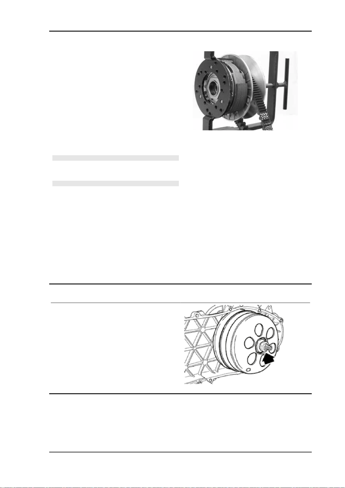
MSS X9 Evolution 250 Engine
- Apply the clutch fixing nut and tighten it to the
prescribed torque using the special 46x55 wrench.
- Loosen the tool clamp and insert the belt according to its direction of rotation.
- Lock the driven pulley again using the specific
tool.
- Preload the clutch return spring with a traction/
rotation combined action and place the belt in the
smaller diameter rolling position.
- Remove the driven pulley /belt unit from the tool.
N.B.
DURING THE SPRING PRELOADING PHASE, BE CARE-
FUL NOT TO DAMAGE THE PLASTIC SPRING STOP AND
THE BUSHING THREADING.
N.B.
FOR DESIGN REASONS, THE NUT IS SLIGHTLY ASYM-
METRIC; THE FLATTEST SURFACE SHOULD BE MOUNTED IN CONTACT WITH THE CLUTCH.
Specific tooling
020444Y Tool for fitting/ removing the driven
pulley clutch
020444Y011 adapter ring
020444Y009 46x55 Wrench
Locking torques (N*m)
Nut locking clutch unit on pulley 55 ÷ 60 Nm
Refitting the driven pulley
- Reassemble the clutch bell and spacer.
ENG - 91
Page 92

Engine MSS X9 Evolution 250
Drive-belt
- Check that the driving belt is not damaged.
- Check the belt width.
Characteristic
250 4T Transmission belt/minimum width
19.5 mm
250 4T Transmission belt/standard width
21.3 ± 0.2 mm
During the wear checks foreseen in the scheduled
maintenance services at 6,000 km; 18,000 km;
etc., check that the rim bottom of the toothing does
not show signs of incisions or cracking (see figure):
The rim bottom of the tooth must not have incisions
or cracking; if it does, change the belt.
Removing the driving pulley
- Turn the crankshaft until the ropes of the pulley
are on a horizontal axis
- Insert the adaptor sleeve of the appropriate tool
in the hole shown in the photograph
ENG - 92
Page 93
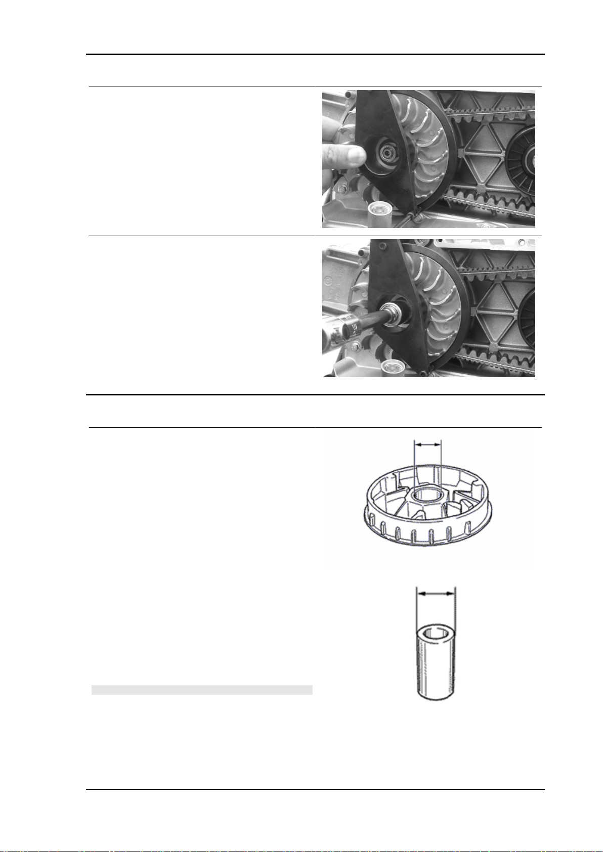
MSS X9 Evolution 250 Engine
- Insert the tool in the hollows and apply the retention ring
- Bring in the ring's clamping screws while keeping
the tool to support the pulley
Specific tooling
020626Y Driving pulley lock wrench
- Remove the fixing nut and the washer
- Remove the stationary drive pulley half.
Inspecting the rollers case
- Check that the internal bushing shown in the figure is not abnormally worn and measure inner
diameter.
- Measure outer diameter B of the pulley sliding
bushing shown in the figure.
- Check that the rollers are not damaged or worn.
- Check the guide shoes for the variator back-plate
are not worn.
- Check the wear of the roller housings and of the
belt contact surfaces on both pulley halves.
- Check that stationary driving pulley does not
show signs of abnormal wear on the grooved edge
and on the surface in contact with the belt.
- Check that the O-ring is not pushed out of shape.
CAUTION
DO NOT LUBRICATE OR CLEAN SINTERED BUSHINGS
Characteristic
Movable driving half-pulley bushing: Standard
Diameter
26.000 - 26.021 mm
ENG - 93
Page 94
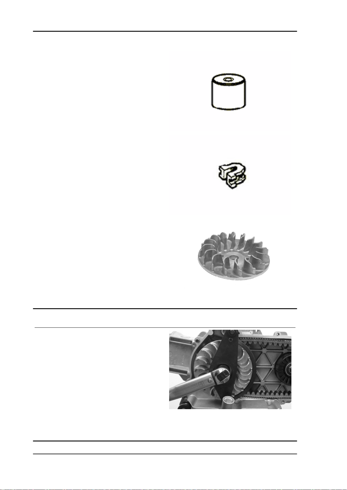
Engine MSS X9 Evolution 250
Movable driving half-pulley bushing: Maximum allowable diameter
Ø 26.12 mm
Sliding bushing: Standard Diameter
Ø 25.959 ÷ 25.98 mm
Sliding bushing: Minimum admissible diameter
Ø 25.95 mm
Roller: Standard Diameter
Diameter 20.5 - 20.7 mm
Roller: Minimum diameter permitted
Ø 20 mm
Refitting the driving pulley
- Fit the steel shim in contact with the bushing and
the stationary drive pulley.
- Install the appropriate tool as described in the removal phase.
-Tighten the nut with washer to the prescribed torque.
Specific tooling
020626Y Driving pulley lock wrench
Locking torques (N*m)
Drive pulley nut 75 ÷ 83
ENG - 94
Page 95

MSS X9 Evolution 250 Engine
Refitting the transmission cover
- Check the presence of the 2 centring dowels and
the correct installation of the sealing gasket for the
oil sump on the transmission cover.
- Replace the cover tightening the 10 screws at the
specified torque.
- Refit the oil loading cap/bar.
- refit the steel washer and the driven pulley nut.
- Tighten the nut to the prescribed torque using the
lock wrench and the torque wrench tools.
- Replace the plastic cover.
Specific tooling
020423Y driven pulley lock wrench
Locking torques (N*m)
Transmission cover screws 11 ÷ 13 Driven pulley shaft nut 54 ÷ 60
End gear
Removing the hub cover
- Empty the rear hub through the oil drainage plug.
- Remove the 7 flanged screws indicated in the
figure.
- Remove the hub cover and its gasket.
ENG - 95
Page 96

Engine MSS X9 Evolution 250
Removing the wheel axle
- Remove the wheel axis complete with gear.
- Remove the intermediate gear.
Removing the hub bearings
- Check the state of the bearings being examined
(wear, clearance and noisiness). If faults are detected, do the following.
- Use the specific bearing extractor to remove the
three 15 mm bearings (2 in the crankcase and 1 in
the hub cover).
Specific tooling
001467Y013 Pliers to extract ø 15-mm bearings
ENG - 96
Page 97

MSS X9 Evolution 250 Engine
Removing the wheel axle bearings
- Take out the clip on the outside of the gearbox
cover.
- Support the hub cover and expel the bearing.
By means of the appropriate tools, remove the oil
guard as in the figure.
Specific tooling
020376Y Adaptor handle
020477Y Adaptor 37 mm
020483Y 30 mm guide
020359Y 42x47-mm adaptor
020489Y Hub cover support stud bolt set
Removing the driven pulley shaft bearing
- As you need to remove the driven pulley shaft, its
bearing and oil guard, remove the transmission
cover as described above.
- Extract the driven pulley shaft from its bearing.
- Remove the oil guard using a screwdriver, working from inside the bearing and being careful not
to damage the housing, make it come out of the
belt transmission side.
- Remove the seeger ring shown in the figure
Remove the driven pulley shaft bearing using the
modular punch.
Specific tooling
020376Y Adaptor handle
020375Y Adaptor 28 x 30 mm
020363Y 20 mm guide
ENG - 97
Page 98

Engine MSS X9 Evolution 250
Inspecting the hub shaft
- Check the three shafts for wear or distortion of
the toothed surfaces, the bearing housings, and
the oil seal housings.
- In case of anomalies, replace the damaged components.
Inspecting the hub cover
- Check that the fitting surface is not dented or distorted.
- Check the bearing bearings.
- In case of anomalies, replace the damaged components.
Refitting the wheel axle bearing
- Support the hub cover on a wooden surface.
- Heat the crankcase cover with the specific heat
gun.
- Fit the wheel shaft bearing with a modular punch
as shown in the figure.
- Fit the seeger ring.
- Fit the oil guard with seal lip towards the inside
of the hub and place it flush with the internal surface by means of the appropriate tool used from
the 52 mm side.
The 52 mm side of the adapter must be turned towards the bearing.
Specific tooling
020376Y Adaptor handle
020360Y Adaptor 52 x 55 mm
020483Y 30 mm guide
ENG - 98
Page 99

MSS X9 Evolution 250 Engine
Refitting the hub cover bearings
- To fit the hub housing bearings, the engine crankcase and the cover must be heated with the special heat gun.
- The three 15 mm bearings must be fitted using
the appropriate tools.
The 42 mm side of the adapter must be turned towards the bearing.
- Refit the driven pulley shaft bearing with a modular punch as shown in the figure.
- Refit the Seeger ring with the opening facing the
bearing and the new oil guard flush with the crankcase on the pulley side.
N.B.
TO FIT THE BEARING ON THE COVER, SUPPORT THE
COVER WITH THE STUD BOLT SET.
N.B.
IF THE BEARING HAS AN ASYMMETRICAL BALL RETAIN-
ER, PLACE IT SO THAT THE BALLS ARE VISIBLE FROM
THE HUB INNER SIDE.
N.B.
WHEN FITTING THE BEARINGS ON THE ENGINE CRANK-
CASE, SUPPORT THE CRANKCASE PREFERABLY ON A
SURFACE TO ALLOW THE BEARINGS TO BE DRIVEN
VERTICALLY.
Specific tooling
020150Y Air heater support
020151Y Air heater
020412Y 15 mm guide
020376Y Adaptor handle
020359Y 42x47-mm adaptor
ENG - 99
Page 100
Engine MSS X9 Evolution 250
020363Y 20 mm guide
Refitting the hub bearings
- Install the three shafts in the engine crankcase as shown in the figure.
Refitting the ub cover
- Fit a new gasket together with the centring dowels.
- Seal the gasket of the breather pipe using black
silicone sealant.
- Fit the gearbox cover, making sure the breather
pipe is in the correct position.
- Place the 3 shortest screws, identifiable by their
different colour, as shown in the figure.
- Fasten the breather pipe support bracket with the
lower short screw.
- Assemble the remaining 4 screws and tighten the
7 screws to the prescribed torque.
Locking torques (N*m)
Rear hub cover screws 24 ÷ 27
ENG - 100
 Loading...