


MANUALE STAZIONE DI SERVIZIO
****** - ****** (IT-EN-FR-DE-ES-EL)
MSS APE 50 (2012)
www.tukxi.com
Tracking ID-422/tukxi/04/2013

MANUALE
STAZIONE DI
SERVIZIO
MSS APE 50 (2012)
© Copyright 2012 - PIAGGIO & C. S.p.A. Pontedera.
All rights reserved. No part of this publication may be reproduced.
This publication has been edited by:
After sales - PIAGGIO & C. S.p.A.
V.le Rinaldo Piaggio, 23 - 56025 PONTEDERA (Pi)
ITALY
www.piaggio.com
www.tukxi.com
Tracking ID-422/tukxi/04/2013

MANUALE STAZIONE DI
SERVIZIO
MSS APE 50 (2012)
MANUALE STAZIONE DI SERVIZIO
Questo manuale per stazioni di servizio è stato realizzato da PIAGGIO & C. Spa per essere utilizzato
dalle officine dei concessionari e sub-agenzie Piaggio. Si presuppone che chi utilizza questa
pubblicazione per la manutenzione e la riparazione dei veicoli Piaggio, abbia una conoscenza base dei
principi della meccanica e dei procedimenti inerenti la tecnica della riparazione dei veicoli. Le variazioni
importanti nelle caratteristiche dei veicoli o nelle specifiche operazioni di riparazione verranno
comunicate attraverso aggiornamenti di questo manuale. Non si può comunque realizzare un lavoro
completamente soddisfacente se non si dispone degli impianti e delle attrezzature necessarie, ed è per
questo che vi invitiamo a consultare le pagine di questo manuale riguardanti l'attrezzatura specifica e il
catalogo degli attrezzi specifici.
Le descrizioni ed illustrazioni fornite nella presente pubblicazione s'intendono non impegnative;
PIAGGIO perciò si riserva il diritto, ferme restando le caratteristiche essenziali del tipo qui descritto ed
illustrato, di apportare in qualunque momento, senza impegnarsi ad aggiornare tempestivamente questa
pubblicazione, le eventuali modifiche di organi, particolari o forniture di accessori, che essa ritenga
conveniente per scopo di miglioramento o per qualsiasi esigenza di carattere costruttivo o commerciale.
Non tutte le versioni riportate nella presente pubblicazione sono disponibili in ogni Paese. La disponibilità
delle singole versioni deve essere verificata con la rete ufficiale di vendita Piaggio.
N.B. Provides key information to make the procedure easier to understand and carry out.
CAUTION Refers to specific procedures to carry out for preventing damages to the vehicle. Refers to
specific procedures to carry out for preventing damages to the vehicle. Refers to specific procedures to
carry out for preventing damages to the vehicle. Refers to specific procedures to carry out for preventing
damages to the vehicle.
WARNING Refers to specific procedures to carry out to prevent injuries to the repairer.
Personal safety Failure to completely observe these instructions will result in serious risk of personal
injury.
www.tukxi.com
Tracking ID-422/tukxi/04/2013

Safeguarding the environment Sections marked with this symbol indicate the correct use of the vehicle
to prevent damaging the environment.
Vehicle intactness The incomplete or non-observance of these regulations leads to the risk of serious
damage to the vehicle and sometimes even the invalidity of the guarantee.
www.tukxi.com
Tracking ID-422/tukxi/04/2013

INDEX OF TOPICS
GENERAL GUIDELINES GEN
CHARACTERISTICS CH
SPECIAL TOOLS ST
MAINTENANCE MA
EMISSION CONTROLO SYSTEM CO EM
TROUBLESHOOTING TROUBL
ELECTRICAL SYSTEM ES
ENGINE FROM VEHICLE EV
ENGINE EN
DIFFERENTIAL DI
BRAKING SYSTEM BS
STEERING COLUMN SC
SUSPENSIONS SS
CHASSIS CH
PRE-DELIVERY PD
TIME-SHEET TEMP
www.tukxi.com
Tracking ID-422/tukxi/04/2013

INDEX OF TOPICS
GENERAL GUIDELINES GEN
www.tukxi.com
Tracking ID-422/tukxi/04/2013

Safety guidelines
- If work can only be done on the vehicle with the engine running, make sure that the premises are well
ventilated, using special extractor fans if necessary; never let the engine run in an enclosed area.
Exhaust gasses are toxic.
The battery electrolyte contains sulphuric acid. Protect your eyes, clothes and skin. Sulphuric acid is
highly corrosive; in the event of contact with your eyes or skin, rinse thoroughly with abundant water
and seek immediate medical attention.
The battery produces hydrogen, a gas that can be highly explosive. Do not smoke and avoid sparks or
flames near the battery, especially when charging it.
Petrol is highly flammable and it can be explosive given some conditions. Do not smoke in the working
area, and avoid open flames or sparks.
- Clean the blocks, the drums, and pads in a well ventilated area, directing the jet of compressed air in
such a way that you do not breathe in the dust produced by the wear of the blocks. Dust caused by
shoe wear is toxic since it contains asbestos.
Maintenance guidelines
Use original PIAGGIO spare parts and lubricants recommended by the Manufacturer. Non-original or
non-conforming spares may damage the vehicle.
Use only the appropriate tools designed for this vehicle. Always use new gaskets, sealing rings and
split pins upon refitting.
After removing these components, clean them using a non-flammable or high flash-point solvent. Lubricate all the work surfaces except the tapered couplings before refitting.
After refitting, make sure that all the components have been installed correctly and work properly.
For disassembly, overhaul and refit operations use only tools with metric measures. Metric bolts, nuts
and screws are not interchangeable with coupling members with English measurement. Using unsuitable coupling members and tools may damage the scooter.
When carrying out maintenance operations on the vehicle that involve the electrical system, make sure
the electrical connections have been made properly, particularly the ground connections.
MSS APE 50 (2012) General guidelines
GEN - 7
www.tukxi.com
Tracking ID-422/tukxi/04/2013

INDEX OF TOPICS
CHARACTERISTICS CH
www.tukxi.com
Tracking ID-422/tukxi/04/2013
Identification
The identification registration numbers are made
up of a prefix that identifies the vehicle type and a
progressive number punched on the chassis and
engine. These numbers must always be quoted in
the spare parts requests.
It is advisable to check that the identification registration numbers on the vehicle and on the engine
correspond with those indicated in the vehicle registration documents.
Check that the prefix and number punched on the
chassis correspond to that shown on the vehicle
documents.
The chassis identification number is located on the
right side of the cross member under the seat.
CAUTION
BE REMINDED THAT ALTERING IDENTIFICATION REGISTRATION NUMBERS MAY LEAD TO SERIOUS PENAL
SANCTIONS (IMPOUNDING OF THE VEHICLE. ETC.)
Check that the prefix and number punched on the
engine correspond to that shown on the vehicle
documents.
The identification number is punched on the left
side of the engine.
CAUTION
BE REMINDED THAT ALTERING IDENTIFICATION REGISTRATION NUMBERS MAY LEAD TO SERIOUS PENAL
SANCTIONS (IMPOUNDING OF THE VEHICLE. ETC.)
Located under the right side seat.
MANUFACTURER'S PLATE KEY:
1. Manufacturer of the vehicle.
2. Type-approval number.
3. Vehicle Identification Number V.I.N.
4. Noise level (dB) under prescribed engine (Rpm)
5. Type of engine.
6. Vehicle code.
MSS APE 50 (2012) Characteristics
CH - 9
www.tukxi.com
Tracking ID-422/tukxi/04/2013
7. Country of production.
COLOUR LABEL:
This colour label indicates:
1. Original paintwork manufacturer
2. Paintwork colour
3. Paintwork code
Characteristics
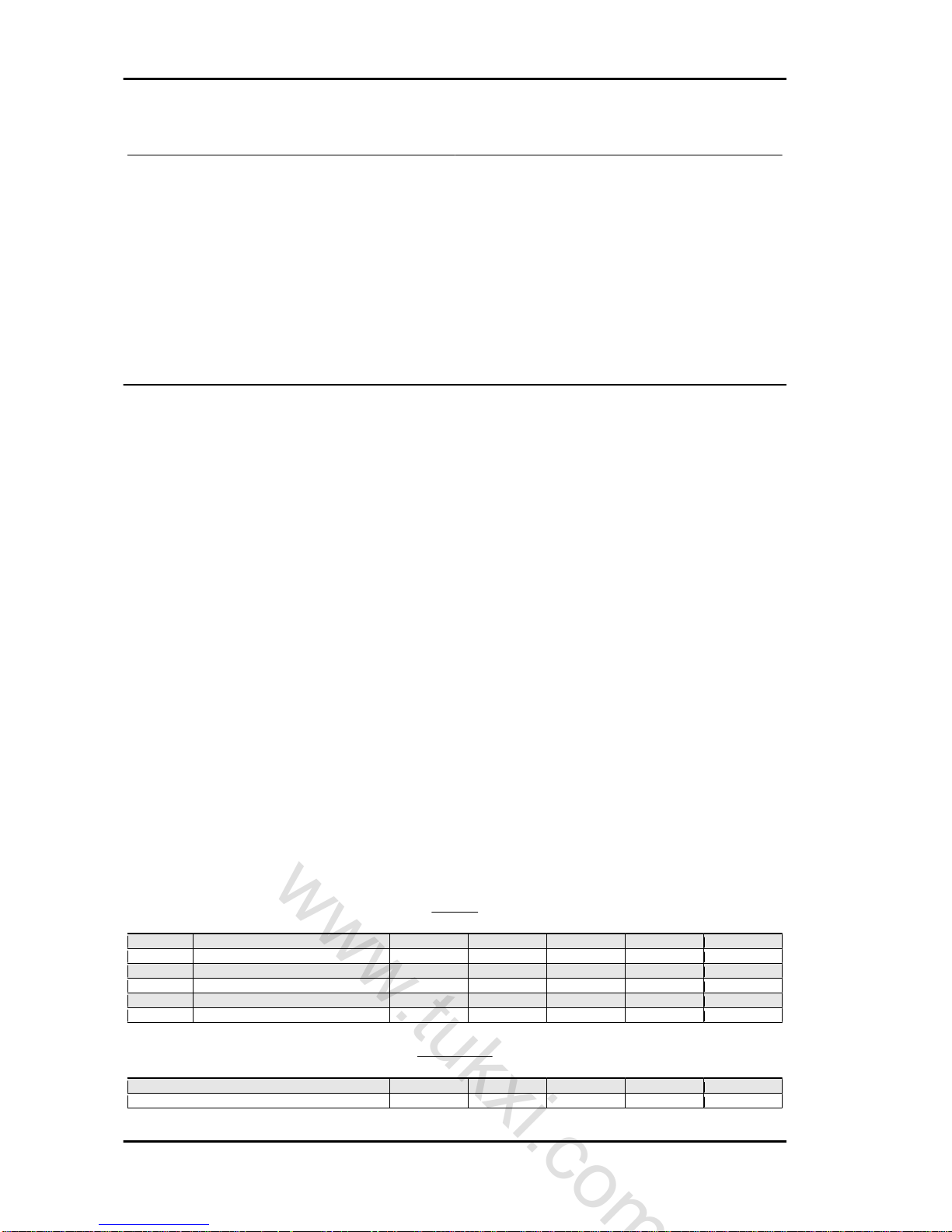
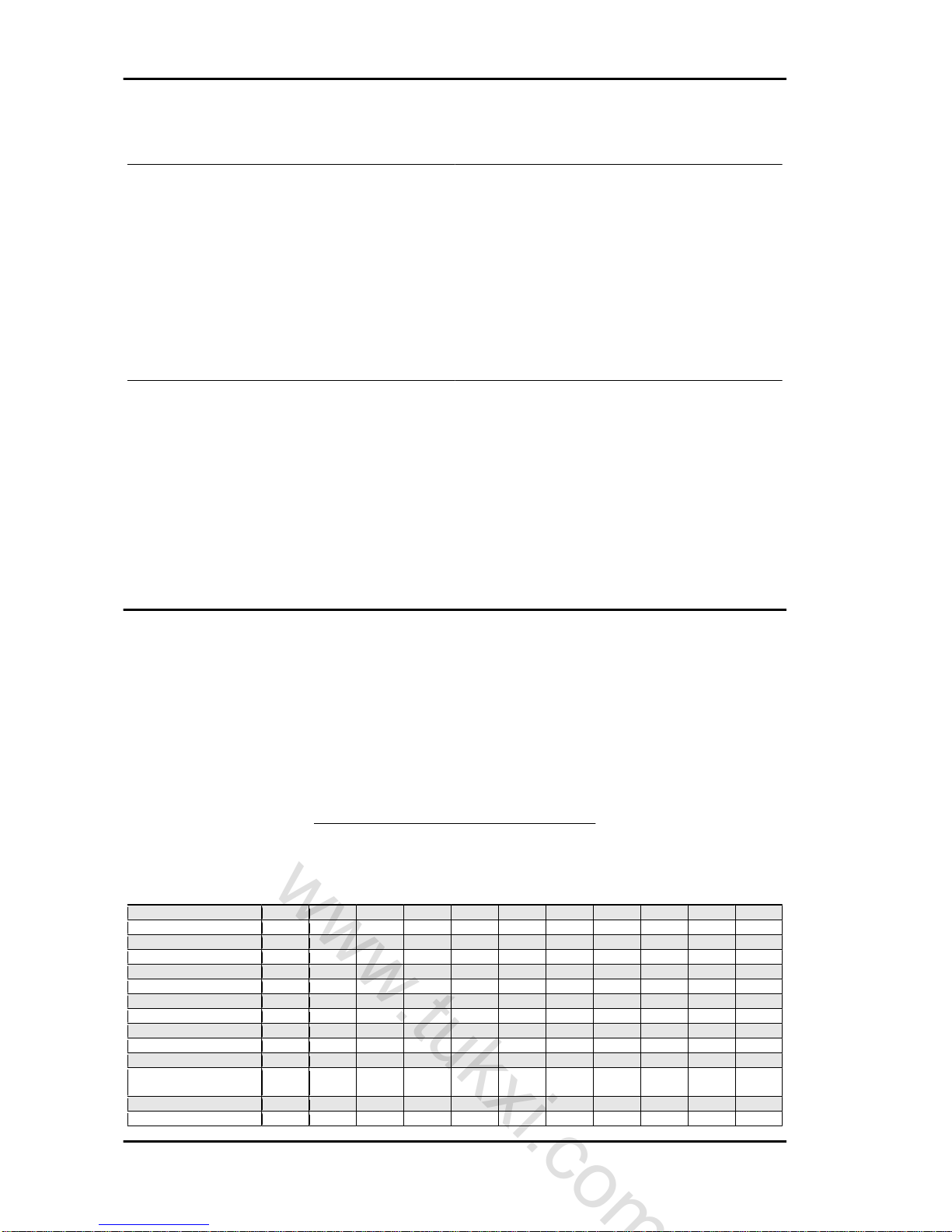
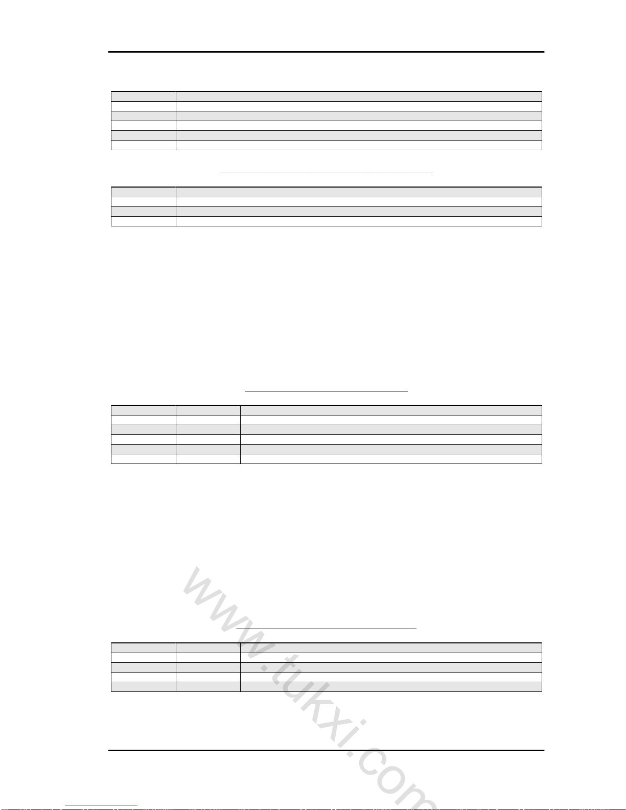
SIZES
N. millimetres (mm) TOP CROSS LONG Deck SHORT deck VAN
1 Length 2660 2700 2660 2490 2500
2 Width 1260 1260 1260 1260 1260
3 Height 1550 1610 1550 1550 1590
4 Wheelbase 1590 1590 1590 1590 1590
5 Deck length 1422 1427 1427 1257 1257
6 Deck width 1262 --- 1211 1211 1211
WEIGHTS
Kilograms (kg) TOP CROSS LONG Deck SHORT deck VAN
Kerb vehicle weight 230 245 230 230 260
Load capacity besides the driver 205 190 205 205 175
Characteristics MSS APE 50 (2012)
CH - 10
www.tukxi.com
Tracking ID-422/tukxi/04/2013
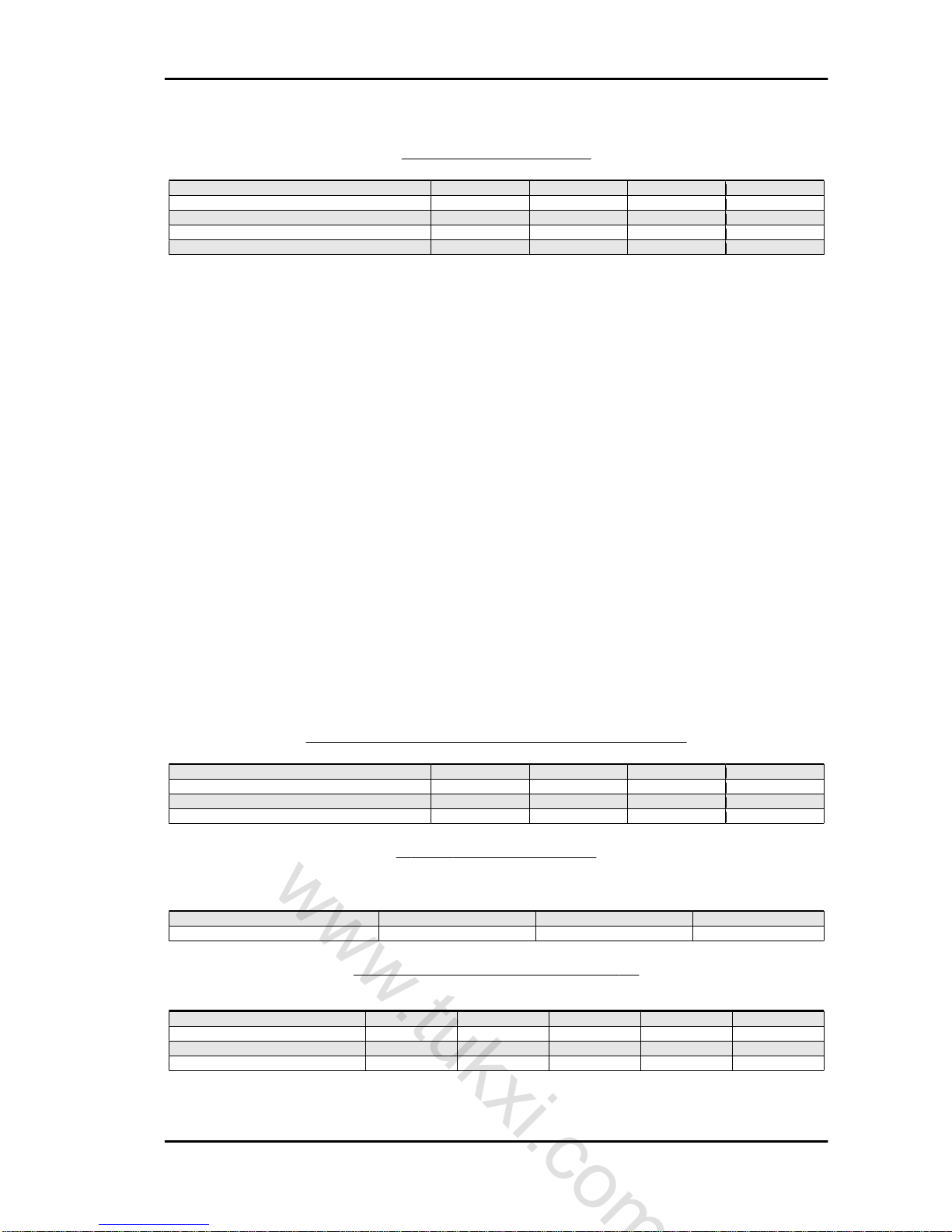
SIZES - APE 50 EUROPA
Sizes (mm) Deck Short deck Van Cross
(1) Length 2660 2520 2560 2580
(2) Width 1250 1250 1250 1270
(3) Height 1530 1530 1560 1580
(4) Wheelbase 1590 1590 1590 1590
(5) Turning spokes 2400 2400 2400 2400
SIZES - LOAD COMPARTMENT - APE 50 EUROPA
Sizes (mm) Deck Short deck Van Cross
(8) Length 1420 1270 1260 1270
(9) Width 1200 1200 1200 1200
(10) Height - - 960 Top box size - - - 900x460x300
WEIGHTS - APE 50 EUROPA
(*) = besides the driver.
Kilograms (kg) Deck Short deck Van
Total dry weight 220 215 250
Useful load capacity (*) 200 205 170
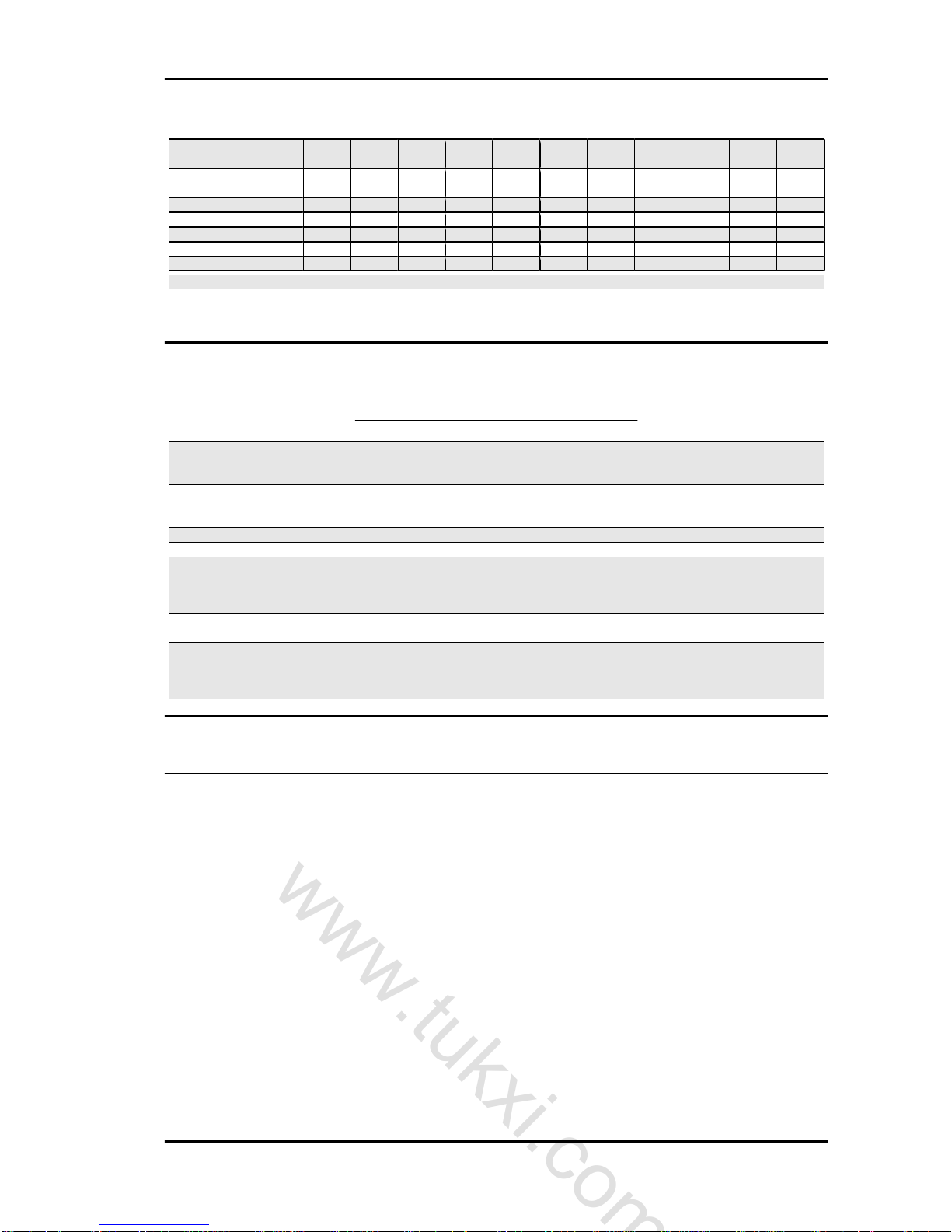
SIZES - APE 50 EUROPE 2 - APE 50 MIX
Sizes (mm) Long deck
base
Short deck
base
Van Cross Top long deck
(1) Length 2660 2490 2500 2700 2660
(2) Width 1260 1260 1260 1260 1260
(3) Height 1550 1550 1590 1610 1550
(4) Wheelbase 1590 1590 1590 1590 1590
MSS APE 50 (2012) Characteristics
CH - 11
www.tukxi.com
Tracking ID-422/tukxi/04/2013
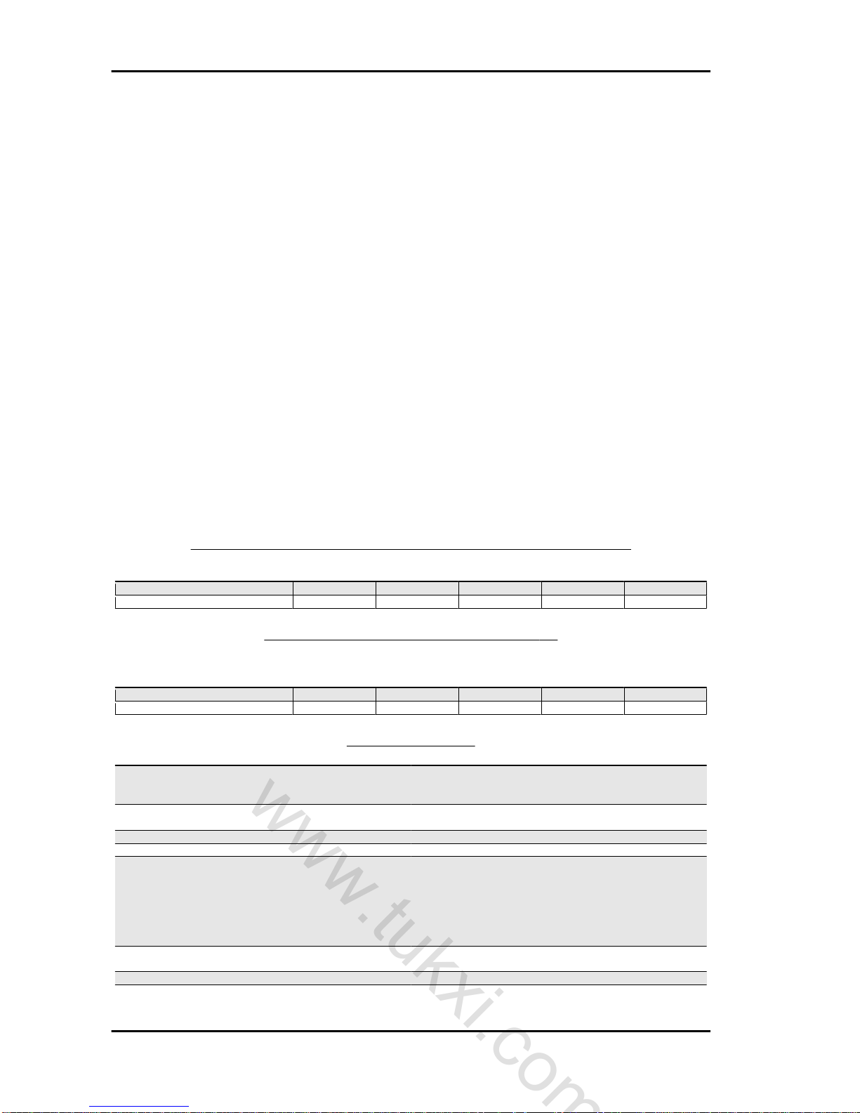
SIZES - LOAD COMPARTMENT - APE 50 EUROPE 2 - APE 50 MIX
Sizes (mm) Long deck
base
Short deck
base
Van Cross Top long deck
(8) Length 1427 1257 1257 1427 1422
(9) Width 1211 1211 1211 1211 1262
WEIGHTS - APE 50 EUROPE 2 - APE 50 MIX
(*) = besides the driver.
Kilograms (kg) Long Deck Short deck Van Cross Top
Total dry weight 230 230 260 245 230
Useful load capacity (*) 205 205 175 190 205
TECHNICAL DATA
Specification Desc./Quantity
Fuel system Mixer petrol - oil through automatic carburettor/mixer (with
slave bearing to the engine speed and throttle valve opening)
and a gravity system.
Lubrication Carried out by the oil mixer for: piston, cylinder, crankshaft,
bearing of the flywheel side bench.
Water cooling, Arrangement for in cab heating system.
Heating Arrangement for in cab heating system.
Electronic ignition Consists of a capacitive discharge type device with H.V. coil
AT built-in. The system allows you to obtain a spark with a high
voltage value, reached in very short time, and with a much reduced discharge duration, so it results in regular operation even
with a dirty spark plug, easy cold starting, excellent combustion,
limited wear of the electrodes and inalterability of the timing due
to the lack of components subject to wear.
Transmission From the crankshaft to the rear wheels through the clutch,
gearbox - differential - axle shaft.
Clutch Multiple discs in oil bath.
Transmission With four speeds with always driven gears.
Characteristics MSS APE 50 (2012)
CH - 12
www.tukxi.com
Tracking ID-422/tukxi/04/2013
Specification Desc./Quantity
N.B.: THERE ARE 3 SPEEDS IN THE VERSION WITH
SPEED LIMITED TO 25 km/h.
Differential Connected to the gearbox shaft by cylinder gears, planetary
and satellite gears are bevel. The differential box is connected
to the two axle shafts that transmit the motion to the wheels.
The differential is equipped with a gear reversing device.
Exhaust silencer Combined, expansion and absorption type with double Cata-
lytic Converter and secondary air system (SAS box).
Steering and suspensions Steering tube pivoted on the oscillating arm with helicoidal
spring and coaxial hydraulic shock absorber; rear suspension
made with two independent oscillating arms with hydraulic
shock absorber and helicoidal springs.
Brakes With expansion on the three wheels:
•
Front: mechanical with control lever on the right
side handlebar.
•
Rear: hydraulically driven by a pedal with direct
control brake pump.
•
Safety: mechanical agent on the rear wheels with
control lever on the footrest central longitudinal
arm, right side internal cab.
Wheels Interchangeable, with printed sheet steel rims.
Wheels: rims from 10 - 2.50"; Michelin S83 tyres 100/90 x 10"
Toolkit Keys: a box-spanner (13/21 mm), a lever for box-spanner, a
screwdriver, a jack, a jack drive rod.
ENGINE
Specification Desc./Quantity
Engine 2-stroke single-cylinder with rotating timing system
Bore 38.4 mm
Stroke 43 mm
Engine capacity 49.8 cm3
Compression ratio 10 ÷ 10.5:1
Ignition advance (before TDC) 15°± 2°
Carburettor Dell'Orto SHBC 18/16P
Engine-wheel transmission ratio 1st spe. 1/54.17
2nd spe. 1/29.75
3a spe. 1/19.28
4a spe. 1/13.35 RM. 1/76.47
N.B.: THERE ARE 3 SPEEDS IN THE VERSION WITH
SPEED LIMITED TO 25 km/h.
Maximum speed Following the applicable regulations
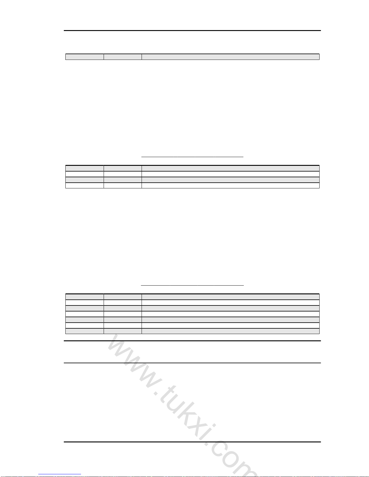
TYRE PRESSURE
Specification Desc./Quantity
Rear tyre pressure 2.2 bar
Front tyre pressure 1.8 bar
TYRES - APE 50 - APE 50 EUROPA - APE 50 EUROPE EURO 2 - APE 50 MIX
Specification Desc./Quantity
Wheel rim 10-2.50"
Tyre 100/90x10"
Front tyre pressure 2 bar.
Rear tyres - inflation pressure 3 bar.
Tightening torques
ENGINE - DIFFERENTIAL UNIT
Name Torque in Nm
Crankcase halves coupling nuts 13 to 15 Nm
Coil support fixing screw 3 to 5 Nm
Spark plug 14 to 18 Nm
Engine gear locking nut 50 to 55 Nm
MSS APE 50 (2012) Characteristics
CH - 13
www.tukxi.com
Tracking ID-422/tukxi/04/2013
Name Torque in Nm
Clutch assembly locking nut 40 ÷ 45 Nm
Fan flywheel locking nut 45 to 50 Nm
Filler joint fixing nuts 5 to 7 Nm
Nuts fixing the exhaust pipe to the cylinder 5 to 7 Nm
Clutch cover fixing bolts 6 to 8 Nm
Big end fixing bolts 13 to 18 Nm
Nuts fixing the cylinder to the crankcase 13 to 15 Nm
Nuts fixing the differential unit to the engine 32 to 35 Nm
Differential crankcase halves coupling nuts 8 to 10 Nm
Engine - chassis anchoring plate fixing nuts 20 to 24 Nm
Differential oil drain plug 20 to 25 Nm
Gear control guide bushing 60 to 65 Nm
Nuts fixing the silencer to the engine support 23 to 25 Nm
Nuts fixing the elastic connection to the engine support 25 to 30 Nm
Engine front fixing bolt 25 to 30 Nm
GRUPPO SOSPENSIONE ANTERIORE
Name Torque in Nm
Front shock absorber (upper part) - Steering tube 34.3 ± 4.9 Nm
Front shock absorber (lower part) - Steering tube 112.7 ± 14.7 Nm
Brake drum - Steering tube 53.9 ± 5 Nm
Front wheel - Brake drum 23.6 ± 4 Nm
GRUPPO SOSPENSIONE POSTERIORE
Name Torque in Nm
Brake drum - Semi axle 85.8 ± 7.4 Nm
Rear wheel - Brake drum 23.6 ± 4 Nm
Shoe holder disc - Wheel hub 23.6 ± 4 Nm
Wheel hub - Rear suspension arm 58.8 ± 9.8 Nm
Rear shock absorber (upper part) - Chassis 34.3 ± 4.9 Nm
Rear shock absorber (lower part) - Wheel hub 34.3 ± 4.9 Nm
Rear suspension arm - Frame 44.1 ± 4.9 Nm
PARTE GENERALE
Name Torque in Nm
Windshield wiper - Chassis (external) 8 ± 0.5 Nm
Rear wheel- Drum 24 ± 4 Nm
Silencer - Engine head 5.9 ± 1 Nm
Silencer - Engine support 23.6 ± 1 Nm
Engine support bracket - Chassis 22 ± 2 Nm
Brake pump - Chassis 15.7 ± 4 Nm
Engine - Chassis 27.5 ± 2.5 Nm
Vehicle overhaul data
Assembly clearances
FITTING CLEARANCES
Name Description Dimensions Initials Quantity
Distance between the
ends of seal rings within
the upper and lower cyl-
inder-ring (mm)
0.2 to 0.3
Gearbox fitting clear-
ance (mm)
0.15 to 0.40
CAUTION
THE GEARBOX SHAFT FITTING CLEARANCE MUST BE VERIFIED WITH THE FEELER GAUGE.
Specific tooling
Characteristics MSS APE 50 (2012)
CH - 14
www.tukxi.com
Tracking ID-422/tukxi/04/2013

060824Y Probe
Cylinder-piston oversizes
CYLINDER - PISTON
Specification Desc./Quantity
Normal cylinder nominal sizes Ø=38.40 +0.025 - 0.005
Normal piston nominal sizes Ø=38.265 ±0.015
CYLINDER COUPLING - PISTON
Name Initials Cylinder Piston Play on fitting
Coupling 1st Oversize 38.600 to 38.620 38.455 to 38.475 0.145
Coupling 2nd Oversize 38.800 to 38.820 38.655 to 38.675 0.145
Coupling 3rd Oversize 39.000 to 39.020 38.855 to 38.875 0.145
Piston ring oversizes
SEALING RINGS
Specification Desc./Quantity
Upper seal ring (Nominal sizes) Diameter=38.40 mm
Lower seal ring (Nominal sizes) Diameter=38.40 mm
CLEARANCE UPON FITTING
Name Description Dimensions Initials Quantity
Upper sealing ring 1st Oversize 38.60 0.20 to 0.60
Lower sealing ring 1st Oversize 38.60 0.20 to 0.60
Upper sealing ring 2nd Oversize 38.80 0.20 to 0.60
Lower sealing ring 2nd Oversize 38.80 0.20 to 0.60
Upper sealing ring 3rd Oversize 39.00 0.20 to 0.60
Lower sealing ring 3rd Oversize 39.00 0.20 to 0.60
Connecting rod - roller cage fitting
CONNECTING ROD - ROLLER CAGE
Connecting rod
Roller cage
1.a category 4.a category
2.a category 3.a category
3.a category 2.a category
4.a category 1.a category
CAUTION
IN CASE OF NOISE, USE CAGE OF THE CATEGORY IMMEDIATELY BELOW.
Crankshaft alignment check
With the proper equipment, check that the eccentricity of the surface of Ø "3"and "1" are contained
within 0.003 mm. (the maximum reading limit on the dial gauge clock); Also check the eccentricity of Ø
"2", which are allowed for a maximum reading of 0.02 mm. In the case of eccentricities not much greater
than that prescribed, perform the straightening of the shaft by means of counterweights with a wedge,
or tightening it in a vice (equipped with aluminium bushings) as needed, for much greater eccentricities
replace the crankshaft.
MSS APE 50 (2012) Characteristics
CH - 15
www.tukxi.com
Tracking ID-422/tukxi/04/2013
Specific tooling
020074Y Crankshaft Alignment Check Tool
Piston - Pin
PISTON - PIN ASSEMBLY CLEARANCE
Name Description Dimensions Initials Quantity
Piston - pin assembly
clearance (mm)
0
Characteristics MSS APE 50 (2012)
CH - 16
www.tukxi.com
Tracking ID-422/tukxi/04/2013
INDEX OF TOPICS
SPECIAL TOOLS ST
www.tukxi.com
Tracking ID-422/tukxi/04/2013

Tooling
SPECIAL TOOLS
Stores code Description
014499Y Bearing extractor
016029Y Lower Steering Bearing Fitting Tool on
the steering tube
017104Y Pliers for circlips
018119Y Axle Fitting Tool
020004Y Steering seats extraction punch
020042Y Steering tube bearing extractor
Special tools MSS APE 50 (2012)
ST - 18
www.tukxi.com
Tracking ID-422/tukxi/04/2013

Stores code Description
020043Y Rear Wheel Hub Roller Bearing Fitting
Punch
020044Y Front Wheel Hub Roller Bearing Fitting
Punch
020055Y Steering Ring Nut Key
020057Y Tool for Starter Motor Bushing Calking
020074Y Crankshaft Alignment Check Tool
020119Y Flywheel extractor
020120Y Punch for Clutch Side Secondary Shaft
Roller Bearing
MSS APE 50 (2012) Special tools
ST - 19
www.tukxi.com
Tracking ID-422/tukxi/04/2013

Stores code Description
020121Y Punch for Flywheel Side Secondary
Shaft Roller Bearing
020123Y Valves Sealing Rings Punch
020125Y Punch to Fit Sealing Rings
020126Y Clutch Stop Key
020127Y Transmission Spider Calking Punch
020128Y Tool to Fit Sealing Rings
020129Y Engine Clearance Gear Check Tool
Special tools MSS APE 50 (2012)
ST - 20
www.tukxi.com
Tracking ID-422/tukxi/04/2013

Stores code Description
020130Y Punch to Fit Roller Casing of Main Shaft,
Flywheel Side Crankcase Half
020131Y Flywheel lock tool
020132Y Gearbox Shaft Shimming Gauge
020133Y Tappet plates replacement tool
020144Y Primary Sprocket Lock
020147Y Flywheel Cone Extractor
020150Y Support
MSS APE 50 (2012) Special tools
ST - 21
www.tukxi.com
Tracking ID-422/tukxi/04/2013

Stores code Description
020151Y Heat gun
020161Y Differential Box Extractor
020322Y Clutch Removal
020781Y Bearings Fitting Punch
020842Y Upper Steering Bearing Removal Punch
021071Y punch to fit bearings and sealing rings
021330Y Steering seats fitting tool
Special tools MSS APE 50 (2012)
ST - 22
www.tukxi.com
Tracking ID-422/tukxi/04/2013
Stores code Description
021467Y Bearing extractor
022465Y Pliers for circlips
023638Y Pliers for circlips
009551Y Clutch puller
029569Y Gear Engagement Fitting Tool
030250Y Clutch Stop Key
032975Y Punches for Roller Casings
MSS APE 50 (2012) Special tools
ST - 23
www.tukxi.com
Tracking ID-422/tukxi/04/2013

Stores code Description
033970Y Punches for Roller Casings
038077Y Engine support
038137Y Rear Hub Extractor
038138Y Roller Casings Punch
048564Y Flywheel extractor
060824Y Probe
020095Y Flywheel Lock
020332Y Digital rev counter
494929 Exhaust fumes analyser
021330Y003 Steering seats fitting
021330Y004 Steering seats fitting
020114Y Pane positioning band
018119Y007 Axle fitting
018119Y009 Axle fitting
018119Y014 Axle fitting
Special tools MSS APE 50 (2012)
ST - 24
www.tukxi.com
Tracking ID-422/tukxi/04/2013

Stores code Description
018119Y015 Axle fitting
021467Y009 extractor
021467Y013 extractor
MSS APE 50 (2012) Special tools
ST - 25
www.tukxi.com
Tracking ID-422/tukxi/04/2013

INDEX OF TOPICS
MAINTENANCE MA
www.tukxi.com
Tracking ID-422/tukxi/04/2013
WINDSCREEN WASHER FLUID TOP-UP - APE
50
Inside the passenger compartment in the front left
part, there is a container for windscreen washer
fluid. If the fluid does not escape when pressing
the button, remove the pipe that goes from the
container to the and blow inside with compressed
air. Do the same for the pipe that goes from the
pump to the external nozzle. Refit everything and
try pressing the button several times to recharge
the system. If despite the above operations, the
fluid does not come out, clean the external nozzle
with iron wire of a suitable diameter.
WINDSCREEN WASHER FLUID TOP-UP- APE
50 EUROPA
The windscreen washer fluid tank is located inside
the passenger compartment, in the front right part.
To fill the tank, unscrew the cover (1), restore the
fluid level and recharge the system by using the
pump on the left side of the passenger compartment several times, until the liquid comes out of
the sprayer.
WINDSCREEN WASHER FLUID TOP-UP APE
50 MIX - APE 50 EUROPE
The windscreen washer fluid tank is located inside
the cab on the front right panel.
To fill the tank, unscrew cover(1), and top up.
Use a specific detergent.
MSS APE 50 (2012) Maintenance
MA - 27
www.tukxi.com
Tracking ID-422/tukxi/04/2013
Manutenzione Batterie
CHARGE CHECK
Connect the terminals of the specific equipment to
the respective poles of the battery.
Check the charge of the battery.
If necessary replace the battery.
Scheduled maintenance chart
The following table must be regarded as a general guide for periodic inspections and lubrication interventions. It is necessary to also consider the weather, terrain, geographic location and variety of special
use. This interventions table must therefore be changed to reflect the particular needs of the owner.
For example, if a vehicle is exposed to sea salt, all parts should be lubricated more frequently than
shown in the table to prevent damage caused by corrosion to metal parts.
SCHEDULED MAINTENANCE TABLE
I: CHECK AND CLEAN, ADJUST, LUBRICATE OR REPLACE, IF NECESSARY C: CLEAN, R: REPLACE, A: ADJUST, L:
LUBRICATE
* Replace every 2 years
km x 1,000 1 5 10 15 20 25 30 35 40 45 50
Brake fluid level * I I I I R I I I R I I
Spark plug R R R R R R R R R R
Air filter C C C C C C C C C C
Gearbox oil I R I R I R I R I R
Differential Oil I R I R I R I R I R
Carburettor I C C C C C
SAS box C C C C C
Clutch and brake lever L L L L L L L L L L
Flexible brake hoses I I I I I
Rear brake pipe R
Flexible transmissions L L L L L
Acceleration/mixer control
A A A A A A A A A A A
Steering clearance I I I I I
Suspension I I I I I
Maintenance MSS APE 50 (2012)
MA - 28
www.tukxi.com
Tracking ID-422/tukxi/04/2013
km x 1,000 1 5 10 15 20 25 30 35 40 45 50
Electrical system and
battery
I I I I I I I I I I I
Hinges - Door locking Transmissions
L L L L L
Tyre pressure and wear I I I I I I I I I I I
Headlights I A A A A A
Safety clamps I I I I I I I I I I I
Test drive I I I I I I I I I I I
OPERATION TIME 60 60 120 60 120 60 150 60 120 60 120
N.B.
THE TIMES LISTED ON THE SCHEDULED MAINTENANCE TABLE INCLUDE THE TIME DEVOTED
TO MANAGEMENT ACTIVITIES.
Suggested products chart
RECOMMENDED PRODUCTS TABLE
Product Description Specifications
eni i-Ride PG 2T Synthetic based Lubricant for 2 stroke
high performance engines.
- API TC
- JASO FC
- ISO-L-EGD
eni i-Ride PG 5W-40 Synthetic based Lubricant for 4 stroke
high performance engines.
- API SL
- ACEA A3
- JASO MA, MA2
AGIP GEAR 80W-90 Oil for gears and transmissions. - API GL-4
AGIP GEAR 80W-90 Oil for gears and transmissions. - API GL-4
AGIP GREASE PV 2 Anhydrous calcium grease suitable for
use with protective functions and lubri-
cants.
- Paste-textured
- Ivory colour
- Specification TL 9150 066, symbol
NATO G 460
AGIP GREASE MU3 Yellow lithium based grease, suitable for
various purposes.
- ISO: L-X-BCHA 3
- DIN 51 825: K3K -20
AGIP BRAKE 4 Synthetic brake fluid. - SAE J 1703
- FMVSS 116 - DOT 3/4
- ISO 4925
- CUNA NC 956 DOT 4
Engine assembly
MSS APE 50 (2012) Maintenance
MA - 29
www.tukxi.com
Tracking ID-422/tukxi/04/2013

Carburettor
KEY:
1. Carburettor
2. Transmission, splitter
3. Cap
4. Nut
5. Gasket
6. Spring
7. Minimum jet
8. Valve
9, Petrol filter
10.Stud bolt
11. Nozzle
12. Needle
13. Pin
14. Float
15. Gasket
16. Spring
17. Spring
18.Ring
Maintenance MSS APE 50 (2012)
MA - 30
www.tukxi.com
Tracking ID-422/tukxi/04/2013

19. Admission joint
20. Admission joint gasket
21. Washer
22. M6 nut
23. Gaskets series
ADJUSTMENT
Perform the idle adjustment.
Perform the mixing adjustment.
REMOVAL
Remove the air filter from the carburettor.
WARNING
THE CARBURETTOR IS VERY EXPLOSIVE; BE VERY CAREFUL NOT TO SPILL FUEL DURING
THE REMOVAL OF THE CARBURETTOR.
WARNING
USE EXTREME CAUTION WHEN WORKING ON COMPONENTS CONTAINING PETROL.
WARNING
PETROL IS HIGHLY EXPLOSIVE.
ALWAYS REPLACE THE GASKETS TO AVOID PETROL LEAKS.
Remove the carburettor from the admission joint,
loosening the fixing ring.
MSS APE 50 (2012) Maintenance
MA - 31
www.tukxi.com
Tracking ID-422/tukxi/04/2013

Remove the tank with its gasket.
Remove the jet.
Remove the needle and the float.
Remove the transmissions with their adjustment
nuts.
Maintenance MSS APE 50 (2012)
MA - 32
www.tukxi.com
Tracking ID-422/tukxi/04/2013

Disassemble the carburettor removing the minimum jet, the needle, the gaskets, the petrol filter.
REVISION
The carburettor is completely decomposed, check
all calibrated parts (main jets, idle jets, emulsifiers
tubes, etc.).
The value of these calibrated parts must correspond to the adjustment data prescribed for the
type of carburettor.
For a thorough cleaning of all components of the
carburettor, use a bath of suitable solvent and blow
with compressed air.
To clean the calibrated jets, avoid using metallic
spikes or wires.
All gaskets, seal rings and springs of the carburettor, should be replaced with each revision.
FITTING
Refit the carburettor, being careful to replace all gaskets, the sealing rings, and the springs.
Install the carburettor on the engine and fit the air filter.
Air filter
REMOVAL
Remove the fixing nuts and the air filter cover.
MSS APE 50 (2012) Maintenance
MA - 33
www.tukxi.com
Tracking ID-422/tukxi/04/2013

Remove the filter and check its state of wear.
Replace if damaged.
Clean with high flammability solvent and dry with
compressed air.
CAUTION
NEVER RUN THE ENGINE WITHOUT THE AIR FILTER.
THIS WOULD RESULT IN AN EXCESSIVE WEAR OF THE
PISTON AND CYLINDER.
FITTING
Insert the filter in position and fit the cover.
Tighten the fixing nuts.
Gear-box oil replacement
REPLACEMENT
Use a suitable container to collect the gear oil
Undo the gearbox oil filler plug.
Remove the drain plug and drain all the oil in the
prepared container.
REFILL
Tighten the drain plug and introduce new oil.
Tighten the filler plug.
Maintenance MSS APE 50 (2012)
MA - 34
www.tukxi.com
Tracking ID-422/tukxi/04/2013

Differential oil replacement
LEVEL CHECK
Start the engine and stop it after having been running for about 1 minute at least.
Remove the control rod and check the oil level.
The oil level should be between the two notches
of the maximum and minimum.
Restore oil level if necessary and check for leaks.
WARNING
DO NOT REMOVE THE OIL COVER IMMEDIATELY AFTER
AN ACTIVITY WITH THE ENGINE AT FULL SPEED AND/OR
WITH THE ENGINE RUNNING. THE HEATED OIL MAY
LEAK, WITH THE RISK OF BURNING.
REPLACEMENT
Use a suitable container to collect the differential oil.
The oil change should be made with the engine warm.
Remove the filler plug with the control rod from the
upper part of the differential crankcase.
WARNING
DO NOT REMOVE THE OIL COVER IMMEDIATELY AFTER
AN ACTIVITY WITH THE ENGINE AT FULL SPEED AND/OR
WITH THE ENGINE RUNNING. THE HEATED OIL MAY
LEAK, WITH THE RISK OF BURNING.
Remove the drain plug and drain all the oil in the
prepared container.
REFILL
Tighten the drain plug and introduce new oil.
Requires approximately 0.600 litres for the engine and about 0.300 litres for the differential.
Locking torques (N*m)
Differential oil drain plug 20 to 25 Nm
Start the engine and stop it after having been running for about 1 minute at least.
MSS APE 50 (2012) Maintenance
MA - 35
www.tukxi.com
Tracking ID-422/tukxi/04/2013

Check the oil level and top up if necessary.
Verify that there are no leaks.
Use specific oils.
Tighten the filler plug.
Spark plug
REMOVAL
Remove the rubber cap.
Undo the spark plug and remove it from the cylinder head.
CHECK
Check the electrode gap and perform the descaling if necessary.
Examine it carefully and if the insulation is chipped
or damaged replace it.
Measure the gap between the electrodes with a
feeler gauge and adjust if necessary, by carefully
bending the outer electrode.
Make sure the sealing washer is in good condition.
Characteristic
Electrode gap
0.6 to 0.7 mm
Recommended spark plugs
Maintenance MSS APE 50 (2012)
MA - 36
www.tukxi.com
Tracking ID-422/tukxi/04/2013

Piaggio P82M; Champion L82C; Bosch W54C;
Lodge 2HN; Ac 430Z.
FITTING
Fit the spark plug, tighten it manually and then lock
it to the prescribed torque with the spark plug
spanner.
Locking torques (N*m)
Spark plug 14 to 18 Nm
Mixer timing
To adjust the timing, operate on the transmission
adjuster screw so that the reference stamped on
the mobile control coincides with that made on the
mixer body.
N.B.
CHECK FOR THE PROPER TIMING OF THE MIXER, IT IS
NECESSARY TO FIRST REMOVE THE METAL COVER
FIXED WITH THREE SCREWS ON THE CLUTCH COVER.
DUE TO THE PASSAGE OF AN EXHAUST PIPE ON ONE OF
THE SCREWS, THE LATTER'S HOUSING HOLE HAS BEEN
MADE OPEN TO REMOVE THE LID BY LOOSENING ONLY
ONE OF THE SCREWS IN QUESTION.
N.B.
WHENEVER REMOVING THE MIXER FROM THE CLUTCH
COVER, THE SEALING O-RING LOCATED ON THE COLLAR OF THE MIXER MUST BE REPLACED.
CAUTION
IN THE EVENT OF REMOVAL OR EXHAUSTION OF THE
OIL IN THE TANK, PROCEED TO BLEED THE MIXER AS
FOLLOWS: WITH THE MIXER FITTED ON THE VEHICLE
WITH THE ENGINE TURNED OFF, PULL OFF THE MIXER
TUBE FROM THE CARBURETTOR AND LOOSEN THE
BLEED SCREW UNTIL OIL STARTS TO FLOW. TIGHTEN
THE SCREW, START THE ENGINE AND WAIT UNTIL OIL
COMES OUT OF THE DELIVERY LINE TO THE CARBURETTOR (PREVIOUSLY DISCONNECTED). RECONNECT
THE PIPE TO THE CARBURETTOR FIXING IT WITH A
BAND.
In carrying out this operation, the engine must be fed with a mixture of 2% of appropriate oil (at least
0.5 litres if the tank is empty).
Recommended products
eni i-Ride PG 2T Synthetic based Lubricant for 2 stroke high performance engines.
- API TC
- JASO FC
- ISO-L-EGD
MSS APE 50 (2012) Maintenance
MA - 37
www.tukxi.com
Tracking ID-422/tukxi/04/2013

Secondary air system
REMOVAL
Undo the fixing screws from the aluminium cover
of the air box.
FILTER CLEANING AND INTEGRITY CHECK
Clean the polyurethane sponge by washing with soap and water then dry fully with compressed air and
reposition everything in its seat.
Verify that the blade is not deformed and/or fails to ensure the seal on its contact surface.
Replace if necessary.
FITTING
Tighten the fixing screws of the cover.
N.B.
WHEN REASSEMBLING, TAKE CARE TO PROPERLY REPOSITION THE BLADE IN ITS SEAT ON
THE TWO PLASTIC AND ALUMINIUM COVERS.
CAUTION
DURING THE OPERATION 1) ALWAYS CHECK THE INTEGRITY AND THE SEAL OF THE RUBBER SLEEVE LOCATED ON THE END OF THE SECONDARY AIR TUBE; IF NECESSARY, REPLACE THE FIXING CLAMPS.
Headlight alignment check
Proceed as follows:
1. Place the vehicle in conditions of use, without load, with the tyres inflated to the prescribed pressure on flat grounds at 10 m
from a white screen placed in semidarkness.
Make sure the vehicle axis is perpendicular
to the screen;
2. Draw two vertical lines "a-a" at a distance
«A» corresponding to the distance between
headlight axes. Draw a horizontal line "b-b"
at height «B» from ground corresponding to
Maintenance MSS APE 50 (2012)
MA - 38
www.tukxi.com
Tracking ID-422/tukxi/04/2013

the headlight centre height from ground multiplied by 0.9;
3. Start the engine and lock the throttle twist
grip at approximately 1/3 of its travel. Switch
the dipped beam headlight on. Direct the
beam so that the horizontal line between the
light and the shade falls above the horizontal
"b-b" drawn on the screen;
4. if this is not so, adjust the headlight by
means of the two screws «A
» to correct any
beam alterations.
CAUTION
BEFORE CARRYING OUT THE OPERATION FOR HEADLIGHTS AIMING, CHECK THAT THE TYRES ARE INFLATED TO THE INDICATED PRESSURES.
Cables adjustment
Throttle pedal adjustment
Position yourself near the carburettor.
Remove the rubber cap from the base.
Adjust by turning the nut.
MSS APE 50 (2012) Maintenance
MA - 39
www.tukxi.com
Tracking ID-422/tukxi/04/2013

Insert the rubber cap.
Air Adjustment
Position yourself near the carburettor.
Remove the rubber cap from the base.
Adjust by turning the nut.
Insert the rubber cap.
Maintenance MSS APE 50 (2012)
MA - 40
www.tukxi.com
Tracking ID-422/tukxi/04/2013

Clutch
ADJUSTMENT
Adjust the clutch transmission by acting on the
threaded ring nut near the clutch lever.
CAMBIO
ADJUSTMENT
The adjustment of the gearbox transmission control is performed within the driver's cab.
Adjust the gearbox transmission control by turning
the nuts.
MSS APE 50 (2012) Maintenance
MA - 41
www.tukxi.com
Tracking ID-422/tukxi/04/2013
INDEX OF TOPICS
EMISSION CONTROLO SYSTEM CO EM
www.tukxi.com
Tracking ID-422/tukxi/04/2013

CO check
The test must be done after a thorough cleaning of all parts of the carburettor, with the air filter clean
and spark plug in good condition
Heat the vehicle for the time necessary to activate
the catalytic converter. Then turn off the vehicle for
the time strictly necessary to carry out the following
operations:
Insert an extension pipe of ~ 50 cm at the exhaust
fumes socket on the silencer.
With the utmost care, ensure the seal between the
silencer and the pipe and insert the probe of the
exhaust fumes analyser into the tube.
Specific tooling
020332Y Digital rev counter
494929 Exhaust fumes analyser
Start the engine and wait for a minute for the idle
to stabilise.
Without ever operating the accelerator and using
the appropriate screw, bring the engine speed to
1350 ±100 rpm.
Record the flow screw in order to have a value of
«CO» at least equal to 2.0 ± 1.0.
Operate the throttle grip by slowly speeding up the
engine to a speed of 4000 rpm. and return to the
closed position:
check that the idle speed remains at the previously
established value, otherwise repeat the procedure.
MSS APE 50 (2012) Emission Controlo System
CO EM - 43
www.tukxi.com
Tracking ID-422/tukxi/04/2013
INDEX OF TOPICS
TROUBLESHOOTING TROUBL
www.tukxi.com
Tracking ID-422/tukxi/04/2013

Probable cause and troubleshooting
DETONATIONS TO THE EXHAUST
Possible Cause Operation
Detonations in the silencer to the gas release Check the ducts and the membrane of the choke device on the
carburettor.
NOISE - KNOCKS
Possible Cause Operation
Worn or leaking shock absorbers Replace.
Flexible buffers of the swinging arms Replace.
Insufficient lubrication of the hubs Remove the hubs and fill the appropriate chamber with special
grease.
RUBBER JOINT FAILURE OF THE SECONDARY PIPE ON THE AIR SILENCER
Possible Cause Operation
Secondary air reed locking Replace.
Secondary air filter clogging Clean the filter and the box.
Clogging of the secondary air joint on the silencer Descale the joint taking care to not let the residues fall into the
silencer.
THE VEHICLE PULLS TO ONE SIDE
Possible Cause Operation
The pressure of one of the tyres is not right Check and set to the prescribed pressure
Rear swinging arms Straighten out if possible, or replace.
Worn rubber buffers Replace.
Engine
ENGINE STOP
Possible Cause Operation
Idle speed too low Work on the appropriate adjuster screw del of the carburettor.
Dirt or water in the mixture of the ducts Clean thoroughly.
Inefficient spark plug Clean and adjust the gap between the electrodes or replace.
Cock obstruction Clean.
H.V. cable or spark plug hood damaged Check or replace.
Fuel tank cap breather obstruction (defective fuel system) Clean properly.
CRANKSHAFT KNOCKS
Possible Cause Operation
Excessive clearance of the main bearings Replace.
Big end failure Replace the crankshaft.
Crankshaft unbalanced Check the alignment
Piston pin worn Replace.
RINGING OF THE PISTON
Possible Cause Operation
Excessive clearance between the piston and cylinder Replace the piston and correct the cylinder.
Excessive clearance of the roller pin-connecting rod small end
or piston pin
Review (for any replacement of the rollers of the connecting rod
small end, see the section "Specifications").
MSS APE 50 (2012) Troubleshooting
TROUBL - 45
www.tukxi.com
Tracking ID-422/tukxi/04/2013
Poor performance
LOW POWER
Possible Cause Operation
Timing incorrect Perform the foreseen checks.
Cylinder head or spark plug not fitted correctly Correct the locking and the fitting.
Leakage of current of the ignition system Locate the dispersion and act accordingly.
Excessive incrustation on the lights of the cylinder Descale.
Silencer blocked Descale with iron wire bent into a hook or with compressed air
introduced into the cylinder nozzle fixed to the cylinder after the
external exhaust pipe.
Starting difficulties
PROBLEMS WITH STARTING
Possible Cause Operation
Battery terminals oxidised or not properly locked Clean, tighten and protect with neutral petroleum jelly
Discharged battery The battery is the electrical device in the system that requires
the most frequent inspections and thorough maintenance. Fre-
quently check that the fluid level fully covers the plates; if not,
restore the level adding distilled water (never use natural water,
even if it is drinking water) and check fluid density at the same
time.
If the vehicle is not used for some time (1 month or longer) the
battery needs to be recharged periodically. The battery runs
down completely in the course of three months. When the battery is being placed on the vehicle, make sure that the connections are not misplaced, keeping in mind that the black ground
cable with the terminal attached to the frame is to be connected
to the negative terminal whereas, the other cable, must be con-
nected to the terminal marked +.
Carburettor body nozzles Remove and clean in petrol; dry with a compressed air jet.
Inefficient spark plug Replace.
Troubleshooting MSS APE 50 (2012)
TROUBL - 46
www.tukxi.com
Tracking ID-422/tukxi/04/2013

Clutch slipping
CLUTCH SLIPPAGE
Possible Cause Operation
Insufficient idle stroke Adjust the stroke.
Weak return spring Replace.
Worn or burned driven disc gasket Replace the disc.
Insufficient oil in the differential transmission or unsuitable oil Restore the oil level or replace.
Gearbox
OIL LOSS FROM THE TRANSMISSION - DIFFERENTIAL UNIT
Possible Cause Operation
Excessive filling Bring back to level.
Loosening of the crankcase halves locking nuts and the differ-
ential cover
Check the locks, replace the gaskets if necessary.
Axle shaft oil seal hood worn or broken Replace.
Cracked crankcase Replace.
Loose oil drain plug Lock and replace if damaged
Gears disengage abruptly or are difficult to engage
SPONTANEOUS GEARS DISENGAGEMENT
Possible Cause Operation
Gearbox housing worn or damaged Verify and replace if necessary
Badly adjusted control cable Adjust.
Trasmission gears or spiders not properly assembled or worn Review.
Noisy gears
NOISY TRANSMISSION
Possible Cause Operation
Excessive clearance between the gears of the transmission Review and replace the worn components.
Insufficient oil in the differential transmission Restore the oil level or replace.
Bearings of the gear shaft are noisy Replace.
Locked brakes
BRAKES LOCKED EVEN WHEN YOU CEASE TO PRESS THE PEDAL
Possible Cause Operation
Return springs stretched Replace.
Compensation hole on the pump clogged Clean and bleed the air out of the system.
Rubber gasket swollen or sized Check the system, replace all the rubber parts and the fluid,
bleed air from the system: use the recommended oil
Noisy suspension
NOISY FRONT SUSPENSION
Possible Cause Operation
Hub bearings worn or with excessive clearance Replace.
The wheel hub chamber needs to be greased Disassemble and apply grease.
MSS APE 50 (2012) Troubleshooting
TROUBL - 47
www.tukxi.com
Tracking ID-422/tukxi/04/2013

Possible Cause Operation
Hydraulic absorber inefficient or discharged Replace.
Roller casings of swinging arm worn Replace.
Difficult riding
GUIDE IRREGULARITIES
Possible Cause Operation
The vehicle "pulls" to one side due to deformation of the steer-
ing tube
Check the steering unit and replace if necessary.
Steering is hard or knocks Check the steering fifth wheels: if they are loose they must be
properly tightened; if marked with pricks, they must be re-
placed.
Troubleshooting MSS APE 50 (2012)
TROUBL - 48
www.tukxi.com
Tracking ID-422/tukxi/04/2013

INDEX OF TOPICS
ELECTRICAL SYSTEM ES
www.tukxi.com
Tracking ID-422/tukxi/04/2013

Dispositivi e accessori
Base electric wiring
COMPONENTS DESCRIPTION
Component Description
D01_01 Starter battery
D02_13 Voltage regulator
D04_10 Starter motor
D04_11 Ignition switch
D04_34 External lights switch
D04_37 Windscreen control switch
D04_53 Ignition device
D04_59 Starter button
D04_60 Stop button on front brake
D04_61 Stop button on rear brake
D04_62 Audible warning device control button
D04_63 Turn signal control deviator
D05_01 Left headlight
D05_02 Right headlight
D05_07 License plate lights
D05_18 Right rear light
D05_19 Left rear light
D05_20 Stop third light
D06_01 Passenger compartment light unit
D07_03 Windshield wiper motor
D07_05 Electric screen washer pump
D07_23 Magneto flywheel
D08_10 Turn signal flasher relay
D08_42 Start-up relay
D08_43 Main fuse
Electrical system MSS APE 50 (2012)
ES - 50
www.tukxi.com
Tracking ID-422/tukxi/04/2013
Component Description
D08_44 Cigarette lighter supply fuse
D08_45 Ancillary supply fuse
D08_46 Headlight supply fuse
D08_47 External lighting supply fuse
D10_02 Engine ground
D10_03 Rear right hand chassis ground
D10_06 Battery ground
D10_07 Chassis/engine ground
D10_10 Ground point services cable harness
D11_15 Fuel level sensor
D11_30 Oil level sensor
D12_01 Instrument panel
D12_03 Digital clock
D13_01 12V socket
D13_05 Horn
CABLES COLOUR DESCRIPTION
Colour Description
B Black
Br Brown
G Green
Gr Grey
L Blue
O Orange
P Rosa
R Red
V Purple
Y Yellow
W White
GB Green-Black
GrL Grey-Blue
LB Blue-Black
RB Red-Black
RL Red-Blue
RGr Red-Grey
RW Red-White
YB Yellow-Black
YG Yellow-Green
WB White-Black
WG White-Green
WL White-Blue
WV White-Purple
ELECTRICAL SIGNALS IDENTIFICATION IN THE DIAGRAM
Colour Description
RED Supply
BLACK Ground lead
BLUE Controls to sensors/electrical devices
GREEN Signals from sensors/electrical devices
It differs from the Cross version by the type of magneto flywheel and voltage regulator
MSS APE 50 (2012) Electrical system
ES - 51
www.tukxi.com
Tracking ID-422/tukxi/04/2013

COMPONENTS DESCRIPTION
Component Description
D01_01 Starter battery
D02_13 Voltage regulator
D04_10 Starter motor
D04_11 Ignition switch
D04_34 External lights switch
D04_37 Windscreen control switch
D04_53 Ignition device
D04_59 Starter button
D04_60 Stop button on front brake
D04_61 Stop button on rear brake
D04_62 Audible warning device control button
D04_63 Turn signal control deviator
D05_01 Left headlight
D05_02 Right headlight
D05_07 License plate lights
D05_18 Right rear light
D05_19 Left rear light
D05_20 Stop third light
D06_01 Passenger compartment light unit
D07_03 Windshield wiper motor
D07_05 Electric screen washer pump
D07_23 Magneto flywheel
D08_10 Turn signal flasher relay
D08_42 Start-up relay
D08_43 Main fuse
D08_44 Cigarette lighter supply fuse
D08_45 Ancillary supply fuse
D08_46 Headlight supply fuse
D08_47 External lighting supply fuse
D10_02 Engine ground
D10_03 Rear right hand chassis ground
Electrical system MSS APE 50 (2012)
ES - 52
www.tukxi.com
Tracking ID-422/tukxi/04/2013
Component Description
D10_06 Battery ground
D10_07 Chassis/engine ground
D10_10 Ground point services cable harness
D11_15 Fuel level sensor
D11_30 Oil level sensor
D12_01 Instrument panel
D12_03 Digital clock
D13_01 12V socket
D13_05 Horn
CABLES COLOUR DESCRIPTION
Colour Description
B Black
Br Brown
G Green
Gr Grey
L Blue
O Orange
P Rosa
R Red
V Purple
Y Yellow
W White
GB Green-Black
GrL Grey-Blue
LB Blue-Black
RB Red-Black
RL Red-Blue
RGr Red-Grey
RW Red-White
YB Yellow-Black
YG Yellow-Green
WB White-Black
WG White-Green
WL White-Blue
WV White-Purple
ELECTRICAL SIGNALS IDENTIFICATION IN THE DIAGRAM
Colour Description
RED Supply
BLACK Ground lead
BLUE Controls to sensors/electrical devices
GREEN Signals from sensors/electrical devices
Key-switch
LOCK Position: contacts 7-8, ground ignition, ex-
tractable key, locked steering.
OFF: contacts 7-8, ground ignition. Key may be
removed.
ON Position: contacts 1 -3 (c.c. to the services)
and 5-6 (Provision to the ignition of the daylight
running light in c.a.). Key may not be removed.
MSS APE 50 (2012) Electrical system
ES - 53
www.tukxi.com
Tracking ID-422/tukxi/04/2013

Position 1: contacts 7-8 (ground ignition) and 3-5
(c.c. to the daylight running light). Parking extractable key.
Turn signal switch
Position 0: no contact.
Position 1: contact between the Blue and White Blue cables.
Position 2: contact between the Blue and Brown
cables.
Horn button
Button in working position, contact between the
White and Grey Black cables.
Headlight switch
Position O: no contact.
Position 1: contact between the Pink and Grey cables.
Position 2: contact between the Pink and Grey and
Purple cables.
Electrical system MSS APE 50 (2012)
ES - 54
www.tukxi.com
Tracking ID-422/tukxi/04/2013

Wiper switch
In working position, contact between the White
and White Black cables.
POSITIONS OF THE WINDSCREEN WIPER
SWITCH - APE 50 MIX - APE 50 EUROPE
0 = Windscreen wiper turned off
1 = Windscreen wiper turned on
2 = Windscreen washer enabling
Pulsante avviamento
In working position, contact between the White
and Green Black cables.
MSS APE 50 (2012) Electrical system
ES - 55
www.tukxi.com
Tracking ID-422/tukxi/04/2013

Interventions
The failure of the alternate current section of the
voltage regulator can cause, depending on the
type of fault, the following problems:
1) Burning of the bulbs (regulator stopped).
2) Operation failure of the lighting (short circuit in
the regulator).
FAILURE 1
Replace the regulator because it is securely inefficient.
FAILURE 2
a) Check the correct current output of the alternator: disconnect the grey regulator cable, place a
voltmeter between the cable and ground to detect
the alternate current voltages and to check that the
output voltage at 3000 rpm is greater than or equal
to 20V.
b) If the checks carried out disclose no failures,
replace the regulator.
c) If replacing the regulator does not restore proper
operation, proceed to the checks of the electrical
system connections.
interventions
The failure of the direct current section of the voltage regulator can cause, depending on the type of
fault, the following problems:
3) Burning of the protective fuse (short circuit in the regulator) and subsequent battery recharge failure.
4) Battery recharge failure(regulator stopped).
FAILURE 3
Replace the regulator, because it is securely inefficient and replace the protective fuse.
FAILURE 4
a) Insert an ammeter between the regulator and the battery and verify that the current ouput at 3000
rpm is greater than 1 amp, with the battery maintained at 13V. If the values are lower than required,
replace the regulator.
Electrical system MSS APE 50 (2012)
ES - 56
www.tukxi.com
Tracking ID-422/tukxi/04/2013
b) If replacing the regulator does not restore proper operation, check the voltage output from the alternator, as in point 2a. Checking the output voltage at 3000 rpm on the c.c. section is greater than or
equal to 25V.
Characteristics
STARTER MOTOR
Specification Desc./Quantity
Rated voltage 12V.
rated power 0.25 Kw.
Rotation Left.
Bench tests
TESTS TO BE PERFORMED AT THE BENCH WHEN THE STARTER MOTOR HAS TO BE OVERHAULED.
1) No-load test: the starter motor, under no-load, must draw a maximum of 30 Amp. with a supply voltage
of 11.5 to 12V and must rotate at rpm 11,000.
2) Load test: braking the starter motor so that it draws 60 Amp, and with a supply voltage of 10 to 10.5
V a torque 0.06 kgm must be obtained, for no lower than 4,600 rpm.
3) Pickup test: with rotor locked and a supply voltage 8 to 8.5V the current drawn must not be higher
than 160 Amp and the torque must be no lower than 0.3 kgm.
N.B.
THE VALUES SHOWN ABOVE MUST BE TAKEN WITH A CHARGED BATTERY AND AFTER THE
STARTER MOTOR HAS BEEN ROTATING FOR 30" UNDER CONDITIONS OF POINT 1.
MSS APE 50 (2012) Electrical system
ES - 57
www.tukxi.com
Tracking ID-422/tukxi/04/2013

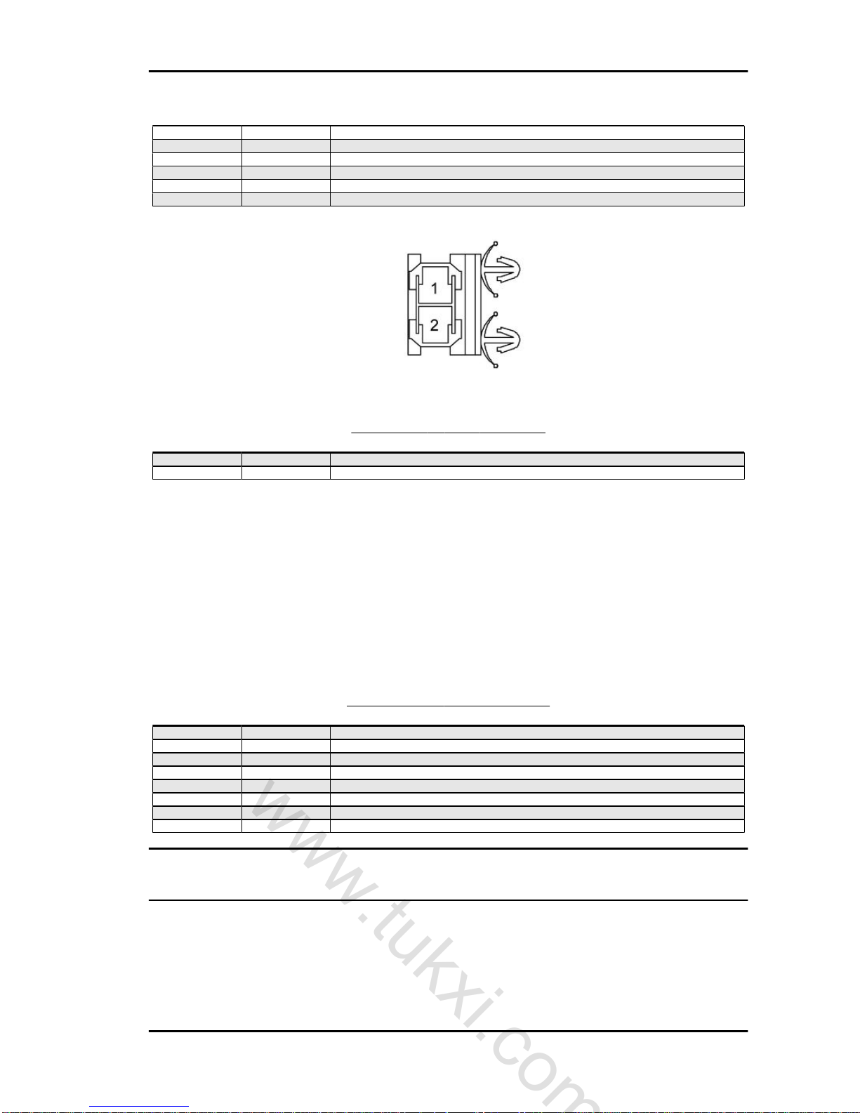
KEY:
1 = Starter button
2 = Remote control
Starter motor removal
Safety cap removal
Coupling pin removal
Remove the retainer ring and remove the pinion.
CAUTION
ALWAYS REPLACE THE INDICATED GASKET GIVEN TO-
GETHER WITH THE SPECIFIC RECOMMENDED PRODUCT.
Electrical system MSS APE 50 (2012)
ES - 58
www.tukxi.com
Tracking ID-422/tukxi/04/2013

Safety cap calkin
- Position the hood.
- Chamfer, as shown, the hood with the appropriate tool.
CAUTION
REPLACING THE BRUSHES, AND REMOVE THE REAR LID
AND REPLACE.
Specific tooling
020057Y Tool for Starter Motor Bushing Calking
Controllo impianto di accensione
All system check operations involving disconnection of the cables (inspections of connections and
devices that are part of the ignition circuit) must be
made with the engine turned off: otherwise the
control unit could be irreparably damaged.
It is therefore important and necessary that in case
of removal of the cables, when refitting attention is
paid to correctly reconnecting each cable to the
corresponding coupling respecting the distinct colour codings.
KEY:
1 = Red
2 = White
3 = Green
INSPECTIONS TO BE PERFORMED IN THE EVENT OF IGNITION IRREGULARITIES
In the event of failure and abnormal operation of the ignition, whose causes are not detectable by a
visual inspection, it is necessary first to replace the control unit with a corresponding, safely functional
replacement.
Remember that the disconnections and connections to replace the control unit must be performed when
the engine stopped.
If replacing it restores the ignition operation, the fault lies in the control unit, which obviously needs to
be replaced.
In the event that the failure persists, it is necessary to carry out checks on the alternator and on the
stator parts as follows:
After a visual inspection of the electrical connections, measurements are carried out on the loading coil
and on the pick-up using an Ohm meter, capable of detecting the resistance from 1 to 1000 ohms.
MSS APE 50 (2012) Electrical system
ES - 59
www.tukxi.com
Tracking ID-422/tukxi/04/2013

Connect the instrument between the green cable
and the white one, there must be continuity and an
ohmic value of 500± 20 ohm.
KEY:
1 = Red
2 = White
3 = Green
4 = Black
5 = Blue
Connect the instrument between the red and white
cables, there must be continuity and an ohmic value of 110± ±5 ohm.
KEY:
1 = Red
2 = White
3 = Green
4 = Black
5 = Blue
If there are failures on the checks on the loading coil and on the pick-up, proceed to the replacement.
ELECTRIC FUNCTIONS
POWER
Starting/Charging
F01_02 Electrical functions, Starting/ Voltage regulator (it differs from the Cross version by the
type of magneto flywheel and voltage regulator)
Electrical system MSS APE 50 (2012)
ES - 60
www.tukxi.com
Tracking ID-422/tukxi/04/2013

Functional Diagram
F01_02 - DESCRIPTION OF COMPONENTS
Component Description
D01_01 Starter battery
D02_13 Voltage regulator
D04_10 Starter motor
D04_11 Ignition switch
D04_53 Ignition device
D04_59 Starter button
D07_23 Magneto flywheel
D08_42 Start-up relay
D08_43 Main fuse
D08_45 Ancillary supply fuse
D10_02 Engine ground
D10_06 Battery ground
D10_07 Chassis/engine ground
D10_10 Ground point services cable harness
CABLES COLOUR DESCRIPTION
Colour Description
B Black
Br Brown
G Green
Gr Grey
L Blue
O Orange
P Rosa
R Red
V Purple
Y Yellow
W White
MSS APE 50 (2012) Electrical system
ES - 61
www.tukxi.com
Tracking ID-422/tukxi/04/2013

Colour Description
GB Green-Black
GrL Grey-Blue
LB Blue-Black
RB Red-Black
RL Red-Blue
RGr Red-Grey
RW Red-White
YB Yellow-Black
YG Yellow-Green
WB White-Black
WG White-Green
WL White-Blue
WV White-Purple
ELECTRICAL SIGNALS IDENTIFICATION IN THE DIAGRAM
Colour Description
RED Supply
BLACK Ground lead
BLUE Controls to sensors/electrical devices
GREEN Signals from sensors/electrical devices
D02_13 - VOLTAGE REGULATOR CONNECTOR (CROSS COUNTRY)
Pin Colour Description
C W Key-on power
L - B RW Power supply from main fuse D08_43 (20A)
G Y Signal from the magneto flywheel
G Y Signal from the magneto flywheel
D04_10 - STARTER MOTOR CONNECTOR
Pin Colour Description
R Starter motor command
Electrical system MSS APE 50 (2012)
ES - 62
www.tukxi.com
Tracking ID-422/tukxi/04/2013

D04_11 - IGNITION SWITCH CONNECTOR
Pin Colour Description
1 B Ground D10_10
2 YB External lighting enable
3 RW Battery positive from main fuse D08_43 (20A)
4 W To fuse D08_45 (7.5A) for ancillary supply
5 O External lights and cigarette lighter lighting power supply enable
6 G Ground signal for ignition device
D04_59 - START-UP BUTTON CONNECTOR
Pin Colour Description
1 GB Starter relay command
2 Gr Positive from fuse D08_45 (7.5A)
D07_23 - MAGNETO FLYWHEEL CONNECTOR (CROSS COUNTRY)
Pin Colour Description
1 B Ground lead
2 - 3 Y Signal to the voltage regulator
4 - -
MSS APE 50 (2012) Electrical system
ES - 63
www.tukxi.com
Tracking ID-422/tukxi/04/2013

Pin Colour Description
5 Y Signal to the voltage regulator
6 - 7 Y Signal to the voltage regulator
D08_42 - START-UP RELAY CONNECTOR
Pin Colour Description
1 - 2 R Direct battery positive
3 - 4 B Ground D10_10
5 - 6 GB Positive from start-up button
7 - 8 R Starter motor command
9 - -
D08_43 - MAIN FUSE CONNECTOR
Pin Colour Description
1 R Direct battery positive
2 RW Ignition switch and voltage regulator power supply
Electrical system MSS APE 50 (2012)
ES - 64
www.tukxi.com
Tracking ID-422/tukxi/04/2013

FUSES TERMINAL BLOCK CONNECTOR
Pin Colour Description
1 O To the external lights switch for activation of daylight running light
2 VB Headlight power supply from fuse D08_46 (4A)
3 Gr Ancillary power supply from fuse D08_45 (7.5A)
4 RL Cigarette lighter power supply from fuse D08_44 (10A)
5 O External lights power supply from fuse D08_47 (4A)
6 V Headlights control of external lights switch
7 W Positive after ignition switch from main fuse D08_43 (20A)
8 RW Battery positive after main fuse D08_43 (20A)
F01_02 Electrical functions Starting / Voltage regulator
Functional Diagram
F01_02 - DESCRIPTION OF COMPONENTS
Component Description
D01_01 Starter battery
D02_13 Voltage regulator
D04_10 Starter motor
D04_11 Ignition switch
D04_53 Ignition device
D04_59 Starter button
D07_23 Magneto flywheel
D08_42 Start-up relay
D08_43 Main fuse
D08_45 Ancillary supply fuse
D10_02 Engine ground
D10_06 Battery ground
D10_07 Chassis/engine ground
D10_10 Ground point services cable harness
MSS APE 50 (2012) Electrical system
ES - 65
www.tukxi.com
Tracking ID-422/tukxi/04/2013

CABLES COLOUR DESCRIPTION
Colour Description
B Black
Br Brown
G Green
Gr Grey
L Blue
O Orange
P Rosa
R Red
V Purple
Y Yellow
W White
GB Green-Black
GrL Grey-Blue
LB Blue-Black
RB Red-Black
RL Red-Blue
RGr Red-Grey
RW Red-White
YB Yellow-Black
YG Yellow-Green
WB White-Black
WG White-Green
WL White-Blue
WV White-Purple
ELECTRICAL SIGNALS IDENTIFICATION IN THE DIAGRAM
Colour Description
RED Supply
BLACK Ground lead
BLUE Controls to sensors/electrical devices
GREEN Signals from sensors/electrical devices
D02_13 - VOLTAGE REGULATOR CONNECTOR
Pin Colour Description
1 RW Power supply from main fuse D08_43 (20A)
2 - 3 B Ground D10_10
4 Y Signal from the magneto flywheel
5 Y Signal from the magneto flywheel
6 Y Signal from the magneto flywheel
Electrical system MSS APE 50 (2012)
ES - 66
www.tukxi.com
Tracking ID-422/tukxi/04/2013

D04_10 - STARTER MOTOR CONNECTOR
Pin Colour Description
R Starter motor command
D04_11 - IGNITION SWITCH CONNECTOR
Pin Colour Description
1 B Ground D10_10
2 YB External lighting enable
3 RW Battery positive from main fuse D08_43 (20A)
4 W To fuse D08_45 (7.5A) for ancillary supply
5 O External lights and cigarette lighter lighting power supply enable
6 G Ground signal for ignition device
D04_53 - IGNITION DEVICE CONNECTOR
Pin Colour Description
1 B Ground D10_07
2 P Signal from the magneto flywheel
3 G Ground signal of ignition switch
4 W Positive from ignition switch
MSS APE 50 (2012) Electrical system
ES - 67
www.tukxi.com
Tracking ID-422/tukxi/04/2013
D04_59 - START-UP BUTTON CONNECTOR
Pin Colour Description
1 GB Starter relay command
2 Gr Positive from fuse D08_45 (7.5A)
D07_23 - MAGNETO FLYWHEEL CONNECTOR
Pin Colour Description
1 B Ground lead
2 P Signal to the ignition device
3 Y Signal to the voltage regulator
4 - 5 Y Signal to the voltage regulator
6 - 7 Y Signal to the voltage regulator
D08_42 - START-UP RELAY CONNECTOR
Pin Colour Description
1 - 2 R Direct battery positive
3 - -
Electrical system MSS APE 50 (2012)
ES - 68
www.tukxi.com
Tracking ID-422/tukxi/04/2013
Pin Colour Description
4 B Ground D10_10
5 - 6 GB Positive from start-up button
7 - 8 R Starter motor command
9 - -
D08_43 - MAIN FUSE CONNECTOR
Pin Colour Description
1 R Direct battery positive
2 RW Ignition switch and voltage regulator power supply
FUSES TERMINAL BLOCK CONNECTOR
Pin Colour Description
1 O To the external lights switch for activation of daylight running light
2 VB Headlight power supply from fuse D08_46 (4A)
3 Gr Ancillary power supply from fuse D08_45 (7.5A)
4 RL Cigarette lighter power supply from fuse D08_44 (10A)
5 O External lights power supply from fuse D08_47 (4A)
6 V Headlights control of external lights switch
7 W Positive after ignition switch from main fuse D08_43 (20A)
8 RW Battery positive after main fuse D08_43 (20A)
ON BOARD INSTRUMENTS
Instrument panel/Warning and indicator lights
F02_01 - Electrical functions, instrument panel/warning and indicator lights
Functional Diagram
MSS APE 50 (2012) Electrical system
ES - 69
www.tukxi.com
Tracking ID-422/tukxi/04/2013

F02_01 - DESCRIPTION OF COMPONENTS
Component Description
D01_01 Starter battery
D04_11 Ignition switch
D08_10 Turn signal flasher relay
D08_43 Main fuse
D08_45 Ancillary supply fuse
D10_06 Battery ground
D10_10 Ground point services cable harness
D11_15 Fuel level sensor
D11_30 Oil level sensor
D12_01 Instrument panel
CABLES COLOUR DESCRIPTION
Colour Description
B Black
Br Brown
G Green
Gr Grey
L Blue
O Orange
P Rosa
R Red
V Purple
Y Yellow
W White
GB Green-Black
GrL Grey-Blue
LB Blue-Black
RB Red-Black
RL Red-Blue
RGr Red-Grey
RW Red-White
Electrical system MSS APE 50 (2012)
ES - 70
www.tukxi.com
Tracking ID-422/tukxi/04/2013
Colour Description
YB Yellow-Black
YG Yellow-Green
WB White-Black
WG White-Green
WL White-Blue
WV White-Purple
ELECTRICAL SIGNALS IDENTIFICATION IN THE DIAGRAM
Colour Description
RED Supply
BLACK Ground lead
BLUE Controls to sensors/electrical devices
GREEN Signals from sensors/electrical devices
D04_11 - IGNITION SWITCH CONNECTOR
Pin Colour Description
1 B Ground D10_10
2 YB External lighting enable
3 RW Battery positive from main fuse D08_43 (20A)
4 W To fuse D08_45 (7.5A) for ancillary supply
5 O External lights and cigarette lighter lighting power supply enable
6 G Ground signal for ignition device
D08_10 - INTERMITTENT RELAY CONNECTOR
Pin Colour Description
1 B Ground D10_10
2 Gr Power supply from fuse D08_45 (7.5A)
3 LB To the turn signal control deviator
4 - 5 WV Intermittent signal for oil level warning light
MSS APE 50 (2012) Electrical system
ES - 71
www.tukxi.com
Tracking ID-422/tukxi/04/2013

D08_43 - MAIN FUSE CONNECTOR
Pin Colour Description
1 R Direct battery positive
2 RW Ignition switch and voltage regulator power supply
FUSES TERMINAL BLOCK CONNECTOR
Pin Colour Description
1 O To the external lights switch for activation of daylight running light
2 VB Headlight power supply from fuse D08_46 (4A)
3 Gr Ancillary power supply from fuse D08_45 (7.5A)
4 RL Cigarette lighter power supply from fuse D08_44 (10A)
5 O External lights power supply from fuse D08_47 (4A)
6 V Headlights control of external lights switch
7 W Positive after ignition switch from main fuse D08_43 (20A)
8 RW Battery positive after main fuse D08_43 (20A)
D11_15 - FUEL LEVEL SENSOR CONNECTOR
Pin Colour Description
1 Gr Positive from fuse D08_45 (7.5A)
2 YG Fuel reserve warning light control
Electrical system MSS APE 50 (2012)
ES - 72
www.tukxi.com
Tracking ID-422/tukxi/04/2013
Pin Colour Description
3 - -
D11_30 - OIL LEVEL SENSOR CONNECTOR
Pin Colour Description
1 WV Oil level warning light control
2 WV Signal of intermittent relay D08_10
3 Gr Positive from fuse D08_45 (7.5A)
4 Gr Positive from fuse D08_45 (7.5A)
D12_01 - INSTRUMENT PANEL CONNECTOR
Pin Colour Description
1 YB Panel lighting and daylight running light warning light power supply activated
2 B Ground D10_10
3 WL Turn signal lights activation
4 P Turn signal lights activation
5 YG fuel reserve indication
6 B Ground D10_10
7 WV Oil level indication
ELECTRICALLY OPERATED DEVICES
Windscreen washer-wiper/Rear screen washer-wiper
F04_01 - Electrical functions. Windscreen wiper-washer/Rear screen wiper-washer
Functional Diagram
MSS APE 50 (2012) Electrical system
ES - 73
www.tukxi.com
Tracking ID-422/tukxi/04/2013

F04_01 - DESCRIPTION OF COMPONENTS
Component Description
D01_01 Starter battery
D04_11 Ignition switch
D04_37 Windscreen control switch
D07_03 Windshield wiper motor
D07_05 Electric screen washer pump
D08_43 Main fuse
D08_45 Ancillary supply fuse
D10_06 Battery ground
D10_10 Ground point services cable harness
CABLES COLOUR DESCRIPTION
Colour Description
B Black
Br Brown
G Green
Gr Grey
L Blue
O Orange
P Rosa
R Red
V Purple
Y Yellow
W White
GB Green-Black
GrL Grey-Blue
LB Blue-Black
RB Red-Black
RL Red-Blue
RGr Red-Grey
RW Red-White
YB Yellow-Black
Electrical system MSS APE 50 (2012)
ES - 74
www.tukxi.com
Tracking ID-422/tukxi/04/2013

Colour Description
YG Yellow-Green
WB White-Black
WG White-Green
WL White-Blue
WV White-Purple
ELECTRICAL SIGNALS IDENTIFICATION IN THE DIAGRAM
Colour Description
RED Supply
BLACK Ground lead
BLUE Controls to sensors/electrical devices
GREEN Signals from sensors/electrical devices
D04_11 - IGNITION SWITCH CONNECTOR
Pin Colour Description
1 B Ground D10_10
2 YB External lighting enable
3 RW Battery positive from main fuse D08_43 (20A)
4 W To fuse D08_45 (7.5A) for ancillary supply
5 O External lights and cigarette lighter lighting power supply enable
6 G Ground signal for ignition device
D04_37 - WINDSCREEN WIPER WASHER CONTROL SWITCH CONNECTOR
Pin Colour Description
1 Gr power supply from fuse D08_45 (7.5A)
2 Br Windscreen wiper control
3 GrL Electric screen washer pump control
MSS APE 50 (2012) Electrical system
ES - 75
www.tukxi.com
Tracking ID-422/tukxi/04/2013

D07_03 - WINDSCREEN WIPER MOTOR CONNECTOR
Pin Colour Description
1 Gr Power supply from fuse D08_45 (7.5A)
2 B Ground D10_10
3 Br Windscreen switch control
D07_05 - ELECTRIC WINDSCREEN WASHER PUMP CONNECTOR
Pin Colour Description
1 B Ground D10_10
2 GrL Control of windscreen wiper washer switch
D08_43 - MAIN FUSE CONNECTOR
Pin Colour Description
1 R Direct battery positive
2 RW Ignition switch and voltage regulator power supply
Electrical system MSS APE 50 (2012)
ES - 76
www.tukxi.com
Tracking ID-422/tukxi/04/2013

FUSES TERMINAL BLOCK CONNECTOR
Pin Colour Description
1 O To the external lights switch for activation of daylight running light
2 VB Headlight power supply from fuse D08_46 (4A)
3 Gr Ancillary power supply from fuse D08_45 (7.5A)
4 RL Cigarette lighter power supply from fuse D08_44 (10A)
5 O External lights power supply from fuse D08_47 (4A)
6 V Headlights control of external lights switch
7 W Positive after ignition switch from main fuse D08_43 (20A)
8 RW Battery positive after main fuse D08_43 (20A)
Horn/Cigarette lighter
F04_03 - Electrical functions, Horn/Cigarette lighter
Functional Diagram
MSS APE 50 (2012) Electrical system
ES - 77
www.tukxi.com
Tracking ID-422/tukxi/04/2013

F04_03 - DESCRIPTION OF COMPONENTS
Component Description
D01_01 Starter battery
D04_11 Ignition switch
D04_62 Audible warning device control button
D08_43 Main fuse
D08_44 Cigarette lighter supply fuse
D08_45 Ancillary supply fuse
D10_06 Battery ground
D10_10 Ground point services cable harness
D13_01 12V socket
D13_05 Horn
CABLES COLOUR DESCRIPTION
Colour Description
B Black
Br Brown
G Green
Gr Grey
L Blue
O Orange
P Rosa
R Red
V Purple
Y Yellow
W White
GB Green-Black
GrL Grey-Blue
LB Blue-Black
RB Red-Black
RL Red-Blue
RGr Red-Grey
RW Red-White
YB Yellow-Black
YG Yellow-Green
WB White-Black
WG White-Green
WL White-Blue
WV White-Purple
ELECTRICAL SIGNALS IDENTIFICATION IN THE DIAGRAM
Colour Description
RED Supply
BLACK Ground lead
BLUE Controls to sensors/electrical devices
GREEN Signals from sensors/electrical devices
Electrical system MSS APE 50 (2012)
ES - 78
www.tukxi.com
Tracking ID-422/tukxi/04/2013

D04_11 - IGNITION SWITCH CONNECTOR
Pin Colour Description
1 B Ground D10_10
2 YB External lighting enable
3 RW Battery positive from main fuse D08_43 (20A)
4 W To fuse D08_45 (7.5A) for ancillary supply
5 O External lights and cigarette lighter lighting power supply enable
6 G Ground signal for ignition device
D04_62 - AUDIBLE WARNING DEVICE CONTROL SWITCH CONNECTOR
Pin Colour Description
1 GrB Audible warning device control
2 Gr Positive from fuse D08_45 (7.5A)
D08_43 - MAIN FUSE CONNECTOR
Pin Colour Description
1 R Direct battery positive
2 RW Ignition switch and voltage regulator power supply
MSS APE 50 (2012) Electrical system
ES - 79
www.tukxi.com
Tracking ID-422/tukxi/04/2013

FUSES TERMINAL BLOCK CONNECTOR
Pin Colour Description
1 O To the external lights switch for activation of daylight running light
2 VB Headlight power supply from fuse D08_46 (4A)
3 Gr Ancillary power supply from fuse D08_45 (7.5A)
4 RL Cigarette lighter power supply from fuse D08_44 (10A)
5 O External lights power supply from fuse D08_47 (4A)
6 V Headlights control of external lights switch
7 W Positive after ignition switch from main fuse D08_43 (20A)
8 RW Battery positive after main fuse D08_43 (20A)
D13_01 - CIGARETTE LIGHTER CONNECTOR
Pin Colour Description
1 Gr Positive for cigarette lighter lighting
2 RL Power supply from fuse D08_44 (10A)
3 B Ground D10_10
D13_05 - HORN CONNECTOR
Pin Colour Description
GrB Audible warning device control
B Ground lead
EXTERNAL LIGHTING
High beam/Low beam/Daylight running lights
F05_01 - Electrical function external lighting
Functional Diagram
Electrical system MSS APE 50 (2012)
ES - 80
www.tukxi.com
Tracking ID-422/tukxi/04/2013

F05_01 - DESCRIPTION OF COMPONENTS
Component Description
D01_01 Starter battery
D04_11 Ignition switch
D04_34 External lights switch
D05_01 Left headlight
D05_02 Right headlight
D05_07 License plate lights
D05_18 Right rear light
D05_19 Left rear light
D08_43 Main fuse
D08_46 Headlight supply fuse
D08_47 External lighting supply fuse
D10_03 Rear right hand chassis ground
D10_06 Battery ground
D10_10 Ground point services cable harness
D12_01 Instrument panel
D13_01 12V socket
CABLES COLOUR DESCRIPTION
Colour Description
B Black
Br Brown
G Green
Gr Grey
L Blue
O Orange
P Rosa
R Red
V Purple
Y Yellow
W White
GB Green-Black
MSS APE 50 (2012) Electrical system
ES - 81
www.tukxi.com
Tracking ID-422/tukxi/04/2013

Colour Description
GrL Grey-Blue
LB Blue-Black
RB Red-Black
RL Red-Blue
RGr Red-Grey
RW Red-White
YB Yellow-Black
YG Yellow-Green
WB White-Black
WG White-Green
WL White-Blue
WV White-Purple
ELECTRICAL SIGNALS IDENTIFICATION IN THE DIAGRAM
Colour Description
RED Supply
BLACK Ground lead
BLUE Controls to sensors/electrical devices
GREEN Signals from sensors/electrical devices
D04_11 - IGNITION SWITCH CONNECTOR
Pin Colour Description
1 B Ground D10_10
2 YB External lighting enable
3 RW Battery positive from main fuse D08_43 (20A)
4 W To fuse D08_45 (7.5A) for ancillary supply
5 O External lights and cigarette lighter lighting power supply enable
6 G Ground signal for ignition device
D04_34 - EXTERNAL LIGHTS SWITCH CONNECTOR
Pin Colour Description
1 W Positive from ignition switch
2 O External lights control
3 V Headlight control
Electrical system MSS APE 50 (2012)
ES - 82
www.tukxi.com
Tracking ID-422/tukxi/04/2013

D05_01/02 - HEADLIGHT CONNECTOR
Pin Colour Description
1 - 2 P/WL Turn signal control
3 VB Headlight control
4 - 5 YB Daylight running lights control
6 B Headlight ground
D05_18/19 - TAILLIGHT CONNECTOR
Pin Colour Description
1 WB Stop light control
2 YB Daylight running lights control
3 B Ground D10_03
4 WL Turn signal control
D08_43 - MAIN FUSE CONNECTOR
Pin Colour Description
1 R Direct battery positive
2 RW Ignition switch and voltage regulator power supply
MSS APE 50 (2012) Electrical system
ES - 83
www.tukxi.com
Tracking ID-422/tukxi/04/2013
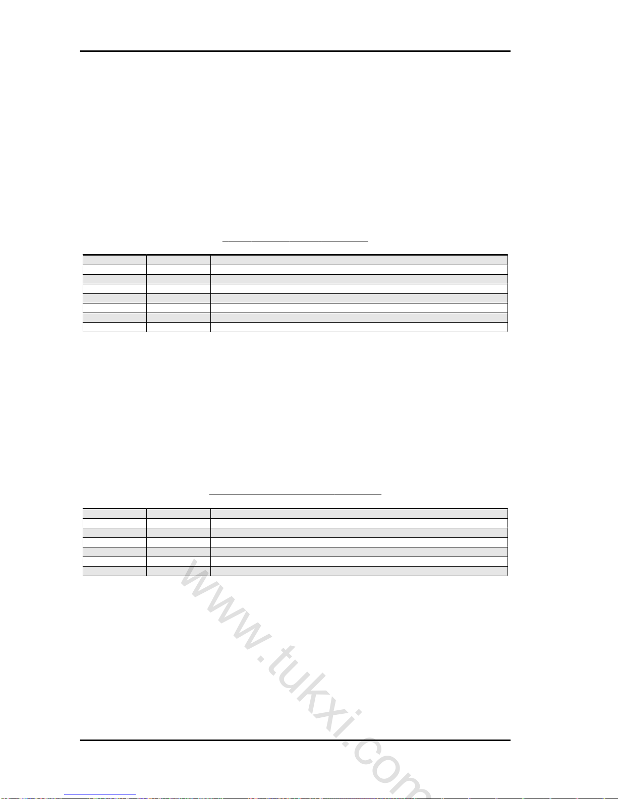
FUSES TERMINAL BLOCK CONNECTOR
Pin Colour Description
1 O To the external lights switch for activation of daylight running light
2 VB Headlight power supply from fuse D08_46 (4A)
3 Gr Ancillary power supply from fuse D08_45 (7.5A)
4 RL Cigarette lighter power supply from fuse D08_44 (10A)
5 O External lights power supply from fuse D08_47 (4A)
6 V Headlights control of external lights switch
7 W Positive after ignition switch from main fuse D08_43 (20A)
8 RW Battery positive after main fuse D08_43 (20A)
D12_01 - INSTRUMENT PANEL CONNECTOR
Pin Colour Description
1 YB Panel lighting and daylight running light warning light power supply activated
2 B Ground D10_10
3 WL Turn signal lights activation
4 P Turn signal lights activation
5 YG fuel reserve indication
6 B Ground D10_10
7 WV Oil level indication
Electrical system MSS APE 50 (2012)
ES - 84
www.tukxi.com
Tracking ID-422/tukxi/04/2013
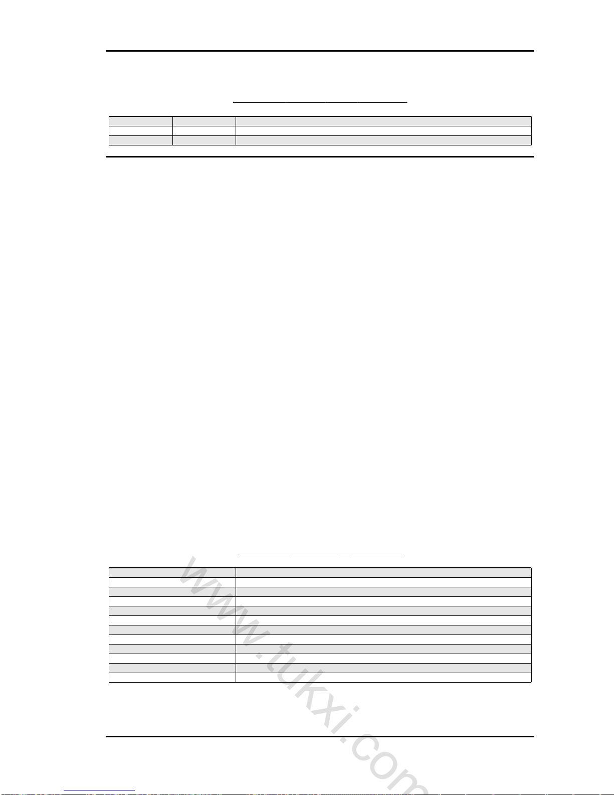
D13_01 - CIGARETTE LIGHTER CONNECTOR
Pin Colour Description
1 Gr Positive for cigarette lighter lighting
2 RL Power supply from fuse D08_44 (10A)
3 B Ground D10_10
Fog light/Rear fog light/Stop lights/Reverse light
F05_03 - Stop lights
Functional Diagram
F05_03 - DESCRIPTION OF COMPONENTS
Component Description
D01_01 Starter battery
D04_11 Ignition switch
D04_60 Stop button on front brake
D04_61 Stop button on rear brake
D05_18 Right rear light
D05_19 Left rear light
D05_20 Stop third light
D08_43 Main fuse
D08_45 Ancillary supply fuse
D10_03 Rear right hand chassis ground
D10_06 Battery ground
D10_10 Ground point services cable harness
MSS APE 50 (2012) Electrical system
ES - 85
www.tukxi.com
Tracking ID-422/tukxi/04/2013
CABLES COLOUR DESCRIPTION
Colour Description
B Black
Br Brown
G Green
Gr Grey
L Blue
O Orange
P Rosa
R Red
V Purple
Y Yellow
W White
GB Green-Black
GrL Grey-Blue
LB Blue-Black
RB Red-Black
RL Red-Blue
RGr Red-Grey
RW Red-White
YB Yellow-Black
YG Yellow-Green
WB White-Black
WG White-Green
WL White-Blue
WV White-Purple
ELECTRICAL SIGNALS IDENTIFICATION IN THE DIAGRAM
Colour Description
RED Supply
BLACK Ground lead
BLUE Controls to sensors/electrical devices
GREEN Signals from sensors/electrical devices
D04_11 - IGNITION SWITCH CONNECTOR
Pin Colour Description
1 B Ground D10_10
2 YB External lighting enable
3 RW Battery positive from main fuse D08_43 (20A)
4 W To fuse D08_45 (7.5A) for ancillary supply
5 O External lights and cigarette lighter lighting power supply enable
6 G Ground signal for ignition device
Electrical system MSS APE 50 (2012)
ES - 86
www.tukxi.com
Tracking ID-422/tukxi/04/2013
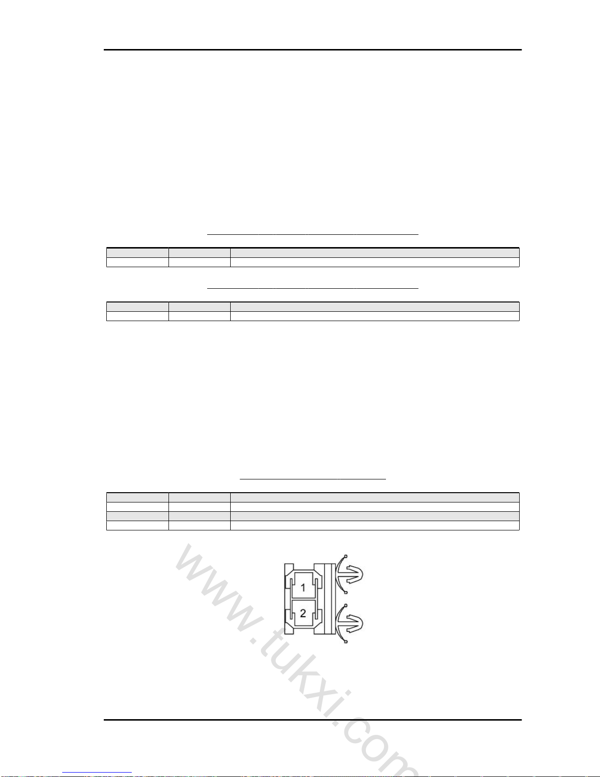
D04_60 - STOP BUTTON CONNECTOR ON REAR BRAKE
Pin Colour Description
Gr Power supply from ancillary fuse D08_45 (7.5A)
WB Stop light control
D04_61 - STOP BUTTON CONNECTOR ON REAR BRAKE
Pin Colour Description
Gr Power supply from ancillary fuse D08_45 (7.5A)
WB Stop light control
D05_18/19 - TAILLIGHT CONNECTOR
Pin Colour Description
1 WB Stop light control
2 YB Daylight running lights control
3 B Ground D10_03
4 WL Turn signal control
MSS APE 50 (2012) Electrical system
ES - 87
www.tukxi.com
Tracking ID-422/tukxi/04/2013
D08_43 - MAIN FUSE CONNECTOR
Pin Colour Description
1 R Direct battery positive
2 RW Ignition switch and voltage regulator power supply
FUSES TERMINAL BLOCK CONNECTOR
Pin Colour Description
1 O To the external lights switch for activation of daylight running light
2 VB Headlight power supply from fuse D08_46 (4A)
3 Gr Ancillary power supply from fuse D08_45 (7.5A)
4 RL Cigarette lighter power supply from fuse D08_44 (10A)
5 O External lights power supply from fuse D08_47 (4A)
6 V Headlights control of external lights switch
7 W Positive after ignition switch from main fuse D08_43 (20A)
8 RW Battery positive after main fuse D08_43 (20A)
Turn indicators/Hazard warning lights
F05_04 - Electrical functions, turn signals lights
Functional Diagram
Electrical system MSS APE 50 (2012)
ES - 88
www.tukxi.com
Tracking ID-422/tukxi/04/2013

F05_04 - DESCRIPTION OF COMPONENTS
Component Description
D01_01 Starter battery
D04_11 Ignition switch
D04_63 Turn signal control deviator
D05_01 Left headlight
D05_02 Right headlight
D05_18 Right rear light
D05_19 Left rear light
D08_10 Turn signal flasher relay
D08_43 Main fuse
D08_45 Ancillary supply fuse
D10_03 Rear right hand chassis ground
D10_06 Battery ground
D10_10 Ground point services cable harness
D12_01 Instrument panel
CABLES COLOUR DESCRIPTION
Colour Description
B Black
Br Brown
G Green
Gr Grey
L Blue
O Orange
P Rosa
R Red
V Purple
Y Yellow
W White
GB Green-Black
GrL Grey-Blue
LB Blue-Black
MSS APE 50 (2012) Electrical system
ES - 89
www.tukxi.com
Tracking ID-422/tukxi/04/2013

Colour Description
RB Red-Black
RL Red-Blue
RGr Red-Grey
RW Red-White
YB Yellow-Black
YG Yellow-Green
WB White-Black
WG White-Green
WL White-Blue
WV White-Purple
ELECTRICAL SIGNALS IDENTIFICATION IN THE DIAGRAM
Colour Description
RED Supply
BLACK Ground lead
BLUE Controls to sensors/electrical devices
GREEN Signals from sensors/electrical devices
D04_11 - IGNITION SWITCH CONNECTOR
Pin Colour Description
1 B Ground D10_10
2 YB External lighting enable
3 RW Battery positive from main fuse D08_43 (20A)
4 W To fuse D08_45 (7.5A) for ancillary supply
5 O External lights and cigarette lighter lighting power supply enable
6 G Ground signal for ignition device
D04_63 - TURN SIGNAL CONTROL DEVIATOR CONNECTOR
Pin Colour Description
1 WL Right hand turn signal control
2 LB Intermittent relay enable
3 P Left hand turn signal control
Electrical system MSS APE 50 (2012)
ES - 90
www.tukxi.com
Tracking ID-422/tukxi/04/2013
D05_01/02 - HEADLIGHT CONNECTOR
Pin Colour Description
1 - 2 P/WL Turn signal control
3 VB Headlight control
4 - 5 YB Daylight running lights control
6 B Headlight ground
D05_18/19 - TAILLIGHT CONNECTOR
Pin Colour Description
1 WB Stop light control
2 YB Daylight running lights control
3 B Ground D10_03
4 WL Turn signal control
D08_10 - INTERMITTENT RELAY CONNECTOR
Pin Colour Description
1 B Ground D10_10
2 Gr Power supply from fuse D08_45 (7.5A)
MSS APE 50 (2012) Electrical system
ES - 91
www.tukxi.com
Tracking ID-422/tukxi/04/2013

Pin Colour Description
3 LB To the turn signal control deviator
4 - 5 WV Intermittent signal for oil level warning light
D08_43 - MAIN FUSE CONNECTOR
Pin Colour Description
1 R Direct battery positive
2 RW Ignition switch and voltage regulator power supply
FUSES TERMINAL BLOCK CONNECTOR
Pin Colour Description
1 O To the external lights switch for activation of daylight running light
2 VB Headlight power supply from fuse D08_46 (4A)
3 Gr Ancillary power supply from fuse D08_45 (7.5A)
4 RL Cigarette lighter power supply from fuse D08_44 (10A)
5 O External lights power supply from fuse D08_47 (4A)
6 V Headlights control of external lights switch
7 W Positive after ignition switch from main fuse D08_43 (20A)
8 RW Battery positive after main fuse D08_43 (20A)
Electrical system MSS APE 50 (2012)
ES - 92
www.tukxi.com
Tracking ID-422/tukxi/04/2013

D12_01 - INSTRUMENT PANEL CONNECTOR
Pin Colour Description
1 YB Panel lighting and daylight running light warning light power supply activated
2 B Ground D10_10
3 WL Turn signal lights activation
4 P Turn signal lights activation
5 YG fuel reserve indication
6 B Ground D10_10
7 WV Oil level indication
INTERNAL LIGHTING
Passenger compartment light
F06_01 - Electrical functions. Passenger compartment interior lighting
Functional Diagram
F06_01 - DESCRIPTION OF COMPONENTS
Component Description
D01_01 Starter battery
D06_01 Passenger compartment light unit
D08_43 Main fuse
D08_44 Cigarette lighter supply fuse
D10_06 Battery ground
MSS APE 50 (2012) Electrical system
ES - 93
www.tukxi.com
Tracking ID-422/tukxi/04/2013

CABLES COLOUR DESCRIPTION
Colour Description
B Black
Br Brown
G Green
Gr Grey
L Blue
O Orange
P Rosa
R Red
V Purple
Y Yellow
W White
GB Green-Black
GrL Grey-Blue
LB Blue-Black
RB Red-Black
RL Red-Blue
RGr Red-Grey
RW Red-White
YB Yellow-Black
YG Yellow-Green
WB White-Black
WG White-Green
WL White-Blue
WV White-Purple
ELECTRICAL SIGNALS IDENTIFICATION IN THE DIAGRAM
Colour Description
RED Supply
BLACK Ground lead
BLUE Controls to sensors/electrical devices
GREEN Signals from sensors/electrical devices
D06_01 - INTERNAL COMPARTMENT LIGHT UNIT CONNECTOR
Pin Colour Description
RL Power supply from fuse D08_44 (10A)
Electrical system MSS APE 50 (2012)
ES - 94
www.tukxi.com
Tracking ID-422/tukxi/04/2013

D08_43 - MAIN FUSE CONNECTOR
Pin Colour Description
1 R Direct battery positive
2 RW Ignition switch and voltage regulator power supply
FUSES TERMINAL BLOCK CONNECTOR
Pin Colour Description
1 O To the external lights switch for activation of daylight running light
2 VB Headlight power supply from fuse D08_46 (4A)
3 Gr Ancillary power supply from fuse D08_45 (7.5A)
4 RL Cigarette lighter power supply from fuse D08_44 (10A)
5 O External lights power supply from fuse D08_47 (4A)
6 V Headlights control of external lights switch
7 W Positive after ignition switch from main fuse D08_43 (20A)
8 RW Battery positive after main fuse D08_43 (20A)
MSS APE 50 (2012) Electrical system
ES - 95
www.tukxi.com
Tracking ID-422/tukxi/04/2013
INDEX OF TOPICS
ENGINE FROM VEHICLE EV
www.tukxi.com
Tracking ID-422/tukxi/04/2013
REMOVAL:
Lift the vehicle using the lift.
Disconnect the positive (+) and negative (-) poles
of the battery.
CAUTION
MAKE SURE THAT THE SIDE ARMS OF THE LIFT ARE
CORRECTLY WELDED AND POSITIONED IN CORRESPONDENCE WITH THE LIFTING POINTS.
Undo the differential oil drain plug.
CAUTION
PREPARE A CONTAINER SUITABLE FOR COLLECTING
BRAKE FLUID.
CAUTION
PAY THE UTMOST ATTENTION NOT TO COME IN CON-
TACT WITH THE OIL.
CAUTION
MAKE SURE THAT THE SIDE ARMS OF THE LIFT ARE
CORRECTLY WELDED AND POSITIONED IN CORRESPONDENCE WITH THE LIFTING POINTS.
Remove the plug and drain the differential oil in a
suitable container.
Retighten the plug, using a new gasket.
CAUTION
WHEN REASSEMBLING ALWAYS USE A NEW GASKET.
MSS APE 50 (2012) Engine from vehicle
EV - 97
www.tukxi.com
Tracking ID-422/tukxi/04/2013

Undo the gearbox oil drain plug.
Remove the plug and drain the gearbox oil in a
suitable container.
Retighten the gearbox oil drain plug.
Undo the screws fastening the flange hood of the
semi axle to the differential crankcase.
Engine from vehicle MSS APE 50 (2012)
EV - 98
www.tukxi.com
Tracking ID-422/tukxi/04/2013

Remove the flange with the hood and using special
pliers remove the retainer ring of the semi axle.
Undo the fixing bolt of the suspension arm to the
frame.
CAUTION
DURING THIS OPERATION, SUPPORT THE REAR SUS-
PENSION ARM.
Remove the bolt.
Remove the rear suspension arm from the frame.
MSS APE 50 (2012) Engine from vehicle
EV - 99
www.tukxi.com
Tracking ID-422/tukxi/04/2013

Press on the wheel so as to move it toward the
outside so as to push the semi axle out of its seat.
Also proceed from the other side of the engine.
CAUTION
DURING THIS OPERATION, ACT WITH CAUTION.
Undo the retaining cylinder of the clutch transmission.
Remove the clutch cable from the engine.
Remove the odometer.
Engine from vehicle MSS APE 50 (2012)
EV - 100
www.tukxi.com
Tracking ID-422/tukxi/04/2013
 Loading...