


579
567

Contents
Safety
Emergency
Controls
Driving
Maintenance
Information
1
2
3
4
5
6
Index 7

Contents
©2013 Paccar Inc - All Rights Reserved
This manual illustrates and describes the operation of features or equipment which may be either standard or optional on this vehicle. This manual may also include a description of features and equipment which are no longer available or were not ordered on this vehicle. Please disregard any illustrations or descriptions relating to features or equipment which are not on this vehicle.
PACCAR reserves the right to discontinue, change specifications, or change the design of its vehicles at any time without notice and without incurring any obligation.
The information contained in this manual is proprietary to PACCAR. Reproduction, in whole or in part, by any means is strictly prohibited without prior written authorization from PACCAR Inc.

Truck Model Example
i


SAFETY
1
INTRODUCTION
How to use this Manual . . . . . . . . . . . . . 1-3
How to Find What You Want . . . . . . . . . . . 1-3
Safety Alerts . . . . . . . . . . . . . . . . . . 1-4
Vehicle Safety . . . . . . . . . . . . . . . . . 1-6
A Special Word About Repairs . . . . . . . . . . 1-8
Additional Sources of Information . . . . . . . . . 1-9
CAB AND FRAME ACCESS
Safety . . . . . . . . . . . . . . . . . . . . 1-10
Door Lock and Keys. . . . . . . . . . . . . . 1-11
Remote Keyless Entry (RKE). . . . . . . . . . 1-12
Climbing onto the Deck Plate. . . . . . . . . . 1-13
GETTING TO YOUR ENGINE
Hood Hold Downs. . . . . . . . . . . . . . . 1-15
Hood Tilt. . . . . . . . . . . . . . . . . . . 1-16
Hood Hold-Open Device . . . . . . . . . . . . 1-17
(04/13) |
Y53-6047–2C |
1-1 |

SAFETY
1 |
SEATS AND RESTRAINTS |
|
|
Introduction . . . . . . . . . . . . . . . . . |
1-19 |
|
Safety Restraint Belts . . . . . . . . . . . . . |
1-22 |
|
Tether Belts . . . . . . . . . . . . . . . . . |
1-25 |
|
Komfort-Latch® Feature . . . . . . . . . . . . |
1-26 |
|
During Pregnancy. . . . . . . . . . . . . . . |
1-28 |
|
Belt Damage and Repair. . . . . . . . . . . . |
1-28 |
|
Sleeper Bunks and Restraints . . . . . . . . . |
1-29 |
|
Safety Restraint Tips . . . . . . . . . . . . . |
1-31 |
START-UP
Introduction . . . . . . . . . . . . . . . . . |
1-33 |
Safe Vehicle Operation . . . . . . . . . . . . |
1-33 |
Vehicle Loading. . . . . . . . . . . . . . . . |
1-34 |
Emergency Equipment . . . . . . . . . . . . |
1-36 |
Driver's Check List . . . . . . . . . . . . . . |
1-36 |
1-2 |
Y53-6047–2C |
(04/13) |
|
|
INTRODUCTION |
|
|
INTRODUCTION |
you need it the next time or when you |
How to Find What You Want |
|
|
|
1 |
|||
|
pass the vehicle on to the next user. |
|
|
How to use this Manual
This manual contains useful information for the safe and efficient operation of your Peterbilt vehicle. It also provides information on maintaining your vehicle in the best
condition, withan outline for performing safety checks and basic preventive maintenance inspections.
We have tried to present the information you’ll need to learn about your vehicle’s functions, controls, and operation—and to present it as clearly as possible. We hope you’ll find this manual easy to use.
There will be times when you need to take this manual out of your Peterbilt. When you do, please be sure to return it to the cab when you are finished using it. That way it will be there when
There are several tools built into this manual to help you find what you need quickly and easily.
First is the Quick Table of Contents. Located at the front of the manual, this lists the main subjects covered and gives section numbers where you can find these subjects. Use the Quick Table of Contents to find information on a large subject like “Maintenance.”
Cross-referenced citations also help you get the information you need. If some other part of the manual contains further information on the subject you are reading about, we’ll indicate that in a cross-reference like this: (See Driver’s Check List on page 1-36). You won’t have to go searching for more information.
Finally you’ll find a helpful Subject Index. It’s in the back of the manual
(04/13) |
Y53-6047–2C |
1-3 |

INTRODUCTION
1 |
and alphabetically lists the subjects |
Safety Alerts |
WARNING |
|
covered. So if you want information on |
Please read and follow all of the |
|
||
WARNING! |
||||
|
brakes, for example, just look under |
|||
|
Brake in the Subject Index. You’ll find |
safety alerts contained in this manual. |
|
|
|
|
|||
|
all the pages listed where brakes or |
They are there for your protection |
|
|
|
|
|||
|
braking are discussed. |
and information. These alerts can |
The safety message following this |
|
|
|
help you avoid injury to yourself, your |
||
|
|
passengers, and help prevent costly |
symbol and signal word provides a |
|
|
|
damage to the vehicle. Safety alerts |
warning against operating procedures |
|
|
|
are highlighted by safety alert symbols |
which could cause death or personal |
|
|
|
and signal words such as "WARNING", |
injury. They could also cause |
|
|
|
"CAUTION", or "NOTE". Please do not |
equipment or property damage. The |
|
|
|
ignore any of these alerts. |
alert will identify the hazard, how to |
|
|
|
|
avoid it, and the probable consequence |
of not avoiding the hazard.
1-4 |
Y53-6047–2C |
(04/13) |
|
|
INTRODUCTION |
|
CAUTION |
NOTE |
1 |
|
Example: |
|
||
WARNING!
Do not carry additional fuel containers in your vehicle. Fuel containers, either full or empty, may leak, explode, and cause or feed a fire. Do not carry extra fuel containers. Even empty ones are dangerous. Failure to comply may result in death or personal injury.
CAUTION |
|
NOTE |
|
|
|
The safety alert following this symbol and signal word provides a caution against operating procedures which could cause equipment or property damage. The alert will identify the hazard, how to avoid it, and the probable consequence of not avoiding the hazard.
Example:
CAUTION
Continuing to operate your vehicle with insufficient oil pressure will cause serious engine damage. Failure to comply may result in equipment or property damage.
The alert following this symbol and signal word provides important information that is not safety related but should be followed. The alert will highlight things that may not be obvious and is useful to your efficient operation of the vehicle.
Example:
NOTE
Pumping the accelerator will not assist
in starting the engine.
(04/13) |
Y53-6047–2C |
1-5 |

INTRODUCTION
1 |
|
Vehicle Safety |
|
|
|
out on the road, it is the responsible |
task. Keep distraction to a minimum to |
|
|
|
|
|
|
|
driver's duty to do so. Inspect the |
improve your concentration. Examples |
|
|
|
WARNING! |
|
|
||||
|
|
|
|
|
vehicle according to the Driver's Check |
of distractions may include radio |
||
|
|
Do not drink alcohol and drive. Your |
List beginning on page 1-36. |
controls, GPS navigation controls, |
||||
|
|
|
cellular telephone calls, cellular text |
|||||
|
|
reflexes, |
perceptions, |
and |
judgment |
Every new vehicle is designed to |
||
|
|
messages, reading or reaching for |
||||||
|
|
can be |
affected by |
even a small |
||||
|
|
conform to all Federal Motor Vehicle |
something on the floor. Minimizing |
|||||
|
|
amount of alcohol. You could have a |
||||||
|
|
Safety Standards applicable at the time |
your distractions will improve safe |
|||||
|
|
serious or even fatal accident, if you |
||||||
|
|
of manufacture. Even with these safety |
driving and will help avoid an accident |
|||||
|
|
drive after drinking. |
Please do |
not |
||||
|
|
features, continued safe and reliable |
involving death or personal injury. |
|||||
|
|
drink and drive or ride with a driver |
||||||
|
|
operation depends greatly upon |
|
|||||
|
|
who has |
been drinking. Failure |
to |
Be aware of local regulations that may |
|||
|
|
regular vehicle maintenance. Follow |
||||||
|
|
comply may result in death, personal |
||||||
|
|
the maintenance recommendations |
prohibit the use of cellular telephones |
|||||
|
|
injury, equipment or property damage. |
||||||
|
|
found in Preventive Maintenance on |
while driving. In addition to being an |
|||||
|
|
|
|
|
|
|
||
|
|
|
|
|
|
|
page 5-9. This will help preserve your |
unsafe practice, it may be against local |
|
|
|
WARNING! |
|
|
|||
|
|
|
|
|
investment. |
or federal ordinances to use cellular |
||
|
|
Do not text and drive. |
Your reaction |
Keep in mind that even a well |
devices while operating the vehicle. |
|||
|
|
time, perceptions and judgment can |
This manual is not a training manual. |
|||||
|
|
maintained vehicle must be operated |
||||||
|
|
be affected while texting or using any |
||||||
|
|
within the range of its mechanical |
It cannot tell you everything you need |
|||||
|
|
other form of mobile messaging while |
||||||
|
|
capabilities and the limits of its load |
to know about driving your vehicle. For |
|||||
|
|
driving. Failure to comply may result |
||||||
|
|
ratings. See the Weight Ratings label |
that you need a good training program |
|||||
|
|
in death, personal injury, equipment or |
||||||
|
|
on the driver's door edge. |
or truck driving school. If you have not |
|||||
|
|
property damage. |
|
|
|
|||
|
|
|
|
|
|
been trained, get the proper training |
||
|
|
|
|
|
|
|
Safe driving is only possible with the |
|
|
|
Make sure your vehicle is in top |
|
before you drive. Only qualified drivers |
||||
|
|
|
proper concentration on the driving |
should drive this vehicle. |
||||
|
|
working condition before heading |
|
|||||
|
|
|
|
|
||||
|
1-6 |
|
|
|
|
Y53-6047–2C |
(04/13) |
|

|
|
INTRODUCTION |
|
California Proposition 65 Warning |
Data Recorder |
Environmental Protection |
1 |
|
|
|
•Diesel engine exhaust and some of its constituents are known to the State of California to cause cancer, birth defects, and other reproductive harm.
•Other chemicals in this vehicle are also known to the State of California to cause cancer, birth defects or other reproductive harm.
•Battery posts, terminals, and related accessories contain lead and lead compounds, chemicals known to the State of California to cause cancer and reproductive harm. Wash hands after handling.
California Vehicle Code - Section
9951Disclosure of Recording Device
Your vehicle may be equipped with one or more recording devices commonly referred to as “event data recorders (EDR)” or “sensing and diagnostic modules (SDM)”. If you are involved in an accident, the device(s) may have the ability to record vehicle data that occurred just prior to and/or during the accident. For additional information on your rights associated with the use of this data, contact
•the California Department of Motor Vehicles - Licensing Operations Division
– or –
•http://www.dmv.ca.gov/
WARNING!
Diesel engine exhaust and some of its constituents are known to the State of California to cause cancer, birth defects, and other reproductive harm. Other chemicals in this vehicle are also known to the State of California to cause cancer, birth defects or other reproductive harm. This warning requirement is mandated by California law (Proposition 65) and does not result from any change in the manner in which vehicles are manufactured.
Some of the ingredients in engine oil, hydraulic oil, transmission and axle oil, engine coolant, diesel fuel, air conditioning refrigerant (R12, R134a, and PAG oil), batteries, etc., may contaminate the environment if spilled or not disposed of properly. Contact your local government agency
(04/13) |
Y53-6047–2C |
1-7 |

INTRODUCTION
1 |
for information concerning proper |
A Special Word About |
must be performed by an authorized |
|
disposal. |
Repairs |
service facility. If you aren’t an |
|
|
|
experienced mechanic, or don’t have |
|
|
WARNING! |
the right equipment, please leave all |
|
|
|
repairs to an authorized service facility. |
|
|
Donotattemptrepairworkwithoutsuf- |
|
|
|
They are the ones equipped to do the |
|
|
|
ficient training, service manuals, and |
|
|
|
job safely and correctly. |
|
|
|
the proper tools. You could be killed |
|
|
|
|
|
|
|
or injured, or you could make your ve- |
Maintenance Manuals. If you do |
|
|
hicle unsafe. Do only those tasks you |
decide to do any complex repair work, |
|
|
are fully qualified to do. |
you’ll need the maintenance manuals. |
|
|
Your dealer’s service center is the best |
Order them from your authorized |
|
|
dealer. Please provide your Chassis |
|
|
|
place to have your vehicle repaired. |
Serial Number when you order, to be |
|
|
You can find dealers all over the |
sure you get the correct manuals for |
|
|
country with the equipment and trained |
your vehicle. Allow about four weeks |
|
|
personnel to get you back on the road |
for delivery. There will be a charge for |
|
|
quickly—and keep you there. |
these manuals. |
|
|
Your vehicle is a complex machine. |
Final Chassis Bill of Material. A |
|
|
Anyone attempting repairs on it needs |
complete, non-illustrated computer |
|
|
good mechanical training and the |
printout listing of the parts used to |
|
|
proper tools. If you are sure you |
custom-build your vehicle is available |
|
|
have these requirements, then you |
through the dealer from whom you |
|
|
can probably perform some repairs |
purchased your vehicle. |
|
|
yourself. However, all warranty repairs |
|
1-8 |
Y53-6047–2C |
(04/13) |

|
|
INTRODUCTION |
|
|
|
Additional Sources of |
Other Sources |
|
|
|
|
1 |
||
WARNING! |
|
|||
Information |
Another place to learn more about |
|
||
Modifying your vehicle can make it un- |
Installed Equipment - Operator's |
|
|
|
trucking is from local truck driving |
|
|
||
safe. Some modifications can affect |
Manuals |
|
|
|
schools. Contact one near you to learn |
|
|
||
your vehicle's electrical system, stabil- |
|
|
|
|
Major component suppliers also supply |
about courses they offer. |
|
|
|
ity, or other important functions. Be- |
|
|
||
foremodifyingyourvehicle, checkwith |
operation manuals specific to their |
Federal and state agencies such |
|
|
your dealer to make sure it can be |
products. Additional manuals and |
|
|
|
as the department of licensing also |
|
|
||
done safely. Improper modifications |
other pieces of literature are included |
|
|
|
have information. The Interstate |
|
|
||
can cause death or personal injury. |
in the glove box literature package. |
|
|
|
Commerce Commission can give |
|
|
||
|
Look for information on products |
|
|
|
|
|
|
||
|
you information about regulations |
|
|
|
|
such as the engine, driver's seat, |
|
|
|
|
governing transportation across state |
|
|
|
|
transmission, axles, wheels, tires, |
|
|
|
|
lines. |
|
|
|
|
ABS/ESP (if applicable), radio, 5th |
|
|
|
|
|
|
|
|
|
wheel, lane departure and adaptive |
|
|
|
|
cruise control. If you are missing these |
|
|
|
|
pieces of literature, ask your Dealer |
|
|
|
|
for copies. |
|
|
|
(04/13) |
Y53-6047–2C |
1-9 |

CAB AND FRAME ACCESS
1 |
|
CAB AND FRAME |
|
|
|
|
WARNING! |
||
|
|
ACCESS |
|
|
|
|
|
Jumping out of the cab or getting into |
|
|
|
|
|
|
|
|
Safety |
|
the cab without proper caution is dan- |
|
|
|
|
gerous. You could slip and fall, which |
|
|
WARNING! |
|
could lead to death or personal injury. |
|
|
|
Keep steps clean. Clean any fuel, oil, |
|
|
|
Always reinstall steps before entering |
|
|
|
|
|
or grease off of the steps before enter- |
|
|
|
the cab or accessing the deck plate. |
|
ing the cab. Use the steps and grab |
|
|
Without steps you could slip and fall. |
|
handles provided, and always keep at |
|
|
Failure to comply may result in death |
|
least three points of contact between |
|
|
or personal injury. |
|
your hands and feet and the truck. Al- |
|
|
|
|
ways face toward the vehicle when |
|
|
Be careful whenever you get into or out |
|
entering or exiting the cab and look |
|
|
of your vehicle’s cab. Always maintain |
|
where you are going. |
|
|
at least three points of contact with |
|
|
|
|
your hands on the grab handles and |
|
The following picture shows the best |
|
|
your feet on the steps. |
|
way to enter and exit a Conventional |
Cab.
1-10 |
Y53-6047–2C |
(04/13) |

|
|
CAB AND FRAME ACCESS |
|
|
Door Lock and Keys |
|
Keys |
|
|
To lock or unlock the doors from |
|
1 |
||
Door Lock |
|
|
||
Doors can be locked from the inside by |
outside the cab, insert the key in the |
The same key fits your ignition, doors, |
|
|
lock. Turn the key toward the rear to |
and sleeper luggage compartment. |
|
|
|
using the lock button. Close the door |
lock; forward to unlock. |
Frame-mounted tool box locks and |
|
|
then push the button down to lock. |
|
|
|
|
Doors automatically unlock when you |
|
locking fuel tank caps each have |
|
|
open them from inside, and can be |
|
individual keys. |
|
|
locked from the outside with the key or |
|
|
|
|
the optional remote keyless entry key |
|
|
|
|
fob. |
|
|
|
|
|
|
|
|
|
WARNING! |
|
|
|
|
To reduce the chance of death or per- |
|
|
|
|
sonal injury, always lock the doors |
|
|
|
|
while driving. Along with using the lap |
|
|
|
|
shoulder belts properly, locking the |
|
|
|
|
doors helps prevent doors from inad- |
|
|
|
|
vertently opening and occupants from |
|
|
|
|
being ejected from the vehicle. |
|
|
|
|
(04/13) |
Y53-6047–2C |
1-11 |

|
|
CAB AND FRAME ACCESS |
|
|
|
|
Remote Keyless Entry (RKE) |
|
Operation |
1 |
|
|||
|
NOTE |
|||
|
|
(Optional) |
|
To Unlock the Driver’s Door |
|
|
This vehicle may be equipped with a |
FCC ID: L2C0031T IC: 3432A-0031T |
Press the UNLOCK button once. The |
|
|
FCC ID: L2C0032R IC: 3432A-0032R |
||
|
|
Remote Keyless Entry (RKE) system |
This device complies with Part 15 of |
driver's door will unlock and the parking |
|
|
that adds security and convenience |
the FCC Rules and with RSS-210 of |
lights will come on for 40 seconds. |
|
|
to your vehicle. The system will |
Industry Canada. |
To Unlock the Passenger’s Door |
|
|
lock or unlock the driver’s door and |
Operation is subject to the following |
|
|
|
|
||
|
|
passenger’s door with the key fob and |
two conditions: |
Press the UNLOCK button once and |
|
|
alert you with parking lights when the |
(1) This device may not cause harmful |
|
|
|
press again within 5 seconds. The |
||
|
|
selected doors are locked or unlocked. |
interference, and |
|
|
|
passenger door will unlock. |
||
|
|
The system includes two key fobs that |
(2) This device must accept any in- |
|
|
|
|
||
|
|
provide secure rolling code technology |
terference received, including interfer- |
To Lock All Doors |
|
|
that prevents someone from recording |
ence that may cause undesired oper- |
|
|
|
the entry signal. |
ation. |
Press the LOCK button. The doors will |
|
|
|
Changes or modifications not expres- |
lock and the parking lights will come |
|
|
|
sively approved by the party respon- |
on for 2 seconds. If the doors are open |
|
|
|
sible for compliance could void the |
they will not lock. The range of the |
|
|
|
user's authority to operate the equip- |
RKE system should be approximately |
|
|
|
ment. The term “IC:” before the radio |
30 ft. This will be reduced if it is |
|
|
|
certification number only signifies that |
operated close to other RF sources |
|
|
|
Industry Canada technical specifica- |
such as TV/radio transmitters and cell |
|
|
|
tions were met. |
towers. |
1-12 |
Y53-6047–2C |
(04/13) |
|
|
CAB AND FRAME ACCESS |
|
|
Batteries |
Synchronization |
Climbing onto the Deck |
|
|
|
1 |
|||
The key fob uses one CR2032, |
The key fob may need to be |
Plate |
|
|
|
|
|||
|
|
|
||
3V battery. Batteries should last |
synchronized to the truck when the |
WARNING! |
|
|
approximately three years, depending |
battery is replaced or when the key fob |
|
|
|
When you are climbing onto and off |
|
|
||
on use. Consistently reduced range |
has not been used for an extended |
|
|
|
is an indicator that the battery needs |
period of time. |
the deck plate, maintain at least three |
|
|
replacement. Batteries are available |
|
points of contact with your hands on |
|
|
at most discount, hardware, and drug |
To Synchronize A Key Fob: |
the grab handles and your feet on the |
|
|
stores. |
1. Hold the key fob near the receiver |
steps. Always face toward the vehicle |
|
|
|
when entering or exiting the cab and |
|
|
|
|
which is located behind the |
|
|
|
The battery can be accessed by |
look where you are going. Failure to |
|
|
|
speedometer and tachometer. |
|
|
||
removing the cover of the key fob. |
complymayresultindeathorpersonal |
|
|
|
|
|
|
||
After a new battery is installed, the |
2. Press and hold both the Lock and |
injury. |
|
|
key fob must be synchronized with the |
Unlock buttons at the same time |
|
|
|
vehicle. |
for approximately 7 seconds. |
WARNING! |
|
|
|
3. When the key fob is |
When stepping onto a surface to enter |
|
|
|
resynchronized, the doors |
the cab or access the deck plate, only |
|
|
|
will lock then immediately unlock. |
use the steps and grab handles in- |
|
|
|
4. If the fob fails to synchronize, |
stalled and designed for that purpose. |
|
|
|
Failure to use the proper steps and |
|
|
|
|
it could be programmed to a |
|
|
|
|
grabhandles could cause a fall which |
|
|
|
|
different truck or could have failed. |
|
|
|
|
may result in death or personal injury. |
|
|
|
|
Contact your dealer to re-program |
|
|
|
|
|
|
|
|
|
your key fob. |
|
|
|
(04/13) |
Y53-6047–2C |
1-13 |

CAB AND FRAME ACCESS
1 |
|
|
|
|
WARNING! |
The following pictures show you the |
|
|
|
Keep steps clean. Clean any fuel, |
right way to get on and off the area |
|
|
behind your cab. |
|
|
|
oil, or grease off the steps before en- |
|
|
|
tering the cab or accessing the deck |
|
|
|
plate. Stepping on a slippery surface |
|
|
|
can cause a fall which may result in |
|
|
|
death or personal injury. |
|
WARNING!
Always reinstall steps before entering the cab or accessing the deck plate. Without steps you could slip and fall. Failure to comply may result in death or personal injury.
NOTE
Any alteration (adding bulkheads, headache racks, tool boxes, etc.) behind the cab that affects the utilization of installed grab handles, deck plates, or frame access steps should comply with Federal Motor Carrier Safety Regulation 399.
Hold handles as you step up.
Maintain three points of contact.
1-14 |
Y53-6047–2C |
(04/13) |

GETTING TO YOUR ENGINE
GETTING TO YOUR |
1. HoodLatchintheClosedPosition |
1 |
|
ENGINE |
|||
|
|
Hood Hold Downs
Hood hold downs keep a hood from opening unexpectedly.
CAUTION
A hood not latched securely could open during operation and cause vehicle damage. Be sure to latch the hood securely.
(04/13) |
Y53-6047–2C |
1-15 |

GETTING TO YOUR ENGINE
1 |
2. Pull Latch to Open |
|
Hood Tilt |
3. Pull Up to Separate |
|||
|
|
|
To open your hood, unlock the hood |
|
|
|
hold downs by unlatching them. Put |
|
|
|
one or both hands on the top of the |
|
|
|
hood front. Tilt the hood forward by |
|
|
|
pulling at the top of the hood keeping |
|
|
|
your feet on the ground for stability. |
|
|
|
Keep pulling on the hood until you are |
|
|
|
certain that the hood hold open device |
|
|
|
is engaged. When closing the hood, |
|
|
|
be sure that you maintain the same |
|
|
|
point of contact (top of hood) to control |
|
|
|
the movement of the hood as it closes. |
|
|
|
|
|
|
|
WARNING! |
|
|
|
A pivoting hood could hurt someone or |
|
|
|
be damaged itself. Before opening or |
|
|
|
closing the hood, be sure there are no |
|
|
|
people or objects in the way. Failure to |
|
|
|
stand in a position of safety can cause |
|
|
|
death or personal injury. |
1-16 |
Y53-6047–2C |
(04/13) |
GETTING TO YOUR ENGINE
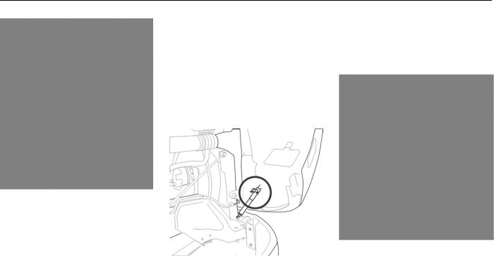
Hood Hold-Open Device |
The release lever for the hood hold |
1 |
|
The hood is equipped with a hood |
|||
open device is located near the front |
|
||
hold-open device. In order for the hood |
hinge of the hood. Press the lever in to |
|
|
hold-open device to become engaged, |
disengage the hood hold open device. |
|
|
the vehicle hood must be fully open. |
|
|
|
Once the vehicle hood is fully open, |
|
|
|
the hold-open latch will automatically |
|
|
|
engage and will need to be disengaged |
|
|
|
by the operator. |
|
|
Pull with hand from here
Press in to disengage
(04/13) |
Y53-6047–2C |
1-17 |

GETTING TO YOUR ENGINE
1 WARNING!
Before opening or closing the hood, make sure your footing is secure and stable. Failure to do so may cause the hood to close uncontrollably which may result in death or personal injury.
WARNING!
Always ensure the hood hold-open latch is engaged to keep the hood fully open any time anyone gets under the hood for any reason. Failure to do so may cause the hood to close uncontrollably which may result in death or personal injury.
WARNING!
Before closing the hood, be sure the areaisclear—nopeopleorobjectsare in the way. Failure to do so may result in death or personal injury.
1-18 |
Y53-6047–2C |
(04/13) |

SEATS AND RESTRAINTS
SEATS AND |
Seat Adjustment |
Suggested Control Setting Order: |
1 |
|
RESTRAINTS |
|
|||
WARNING! |
1. |
Seat fore/aft position |
|
|
|
||||
|
|
|||
Introduction |
Do not adjust the driver's seat while |
2. |
Seat height |
|
|
the vehicle is moving. The seat could |
|
|
|
This section covers the operation |
move suddenly and unexpectedly and |
3. |
Thigh support |
|
and safe use of your seats. For |
can cause the driver to lose control of |
4. |
Seat bottom angle |
|
further information on features and |
the vehicle. Make all adjustments to |
|
||
|
|
|
||
adjustment of the seat, see the |
the seat while the vehicle is stopped. |
5. |
Seat back recline angle |
|
manufacturer's Service and Operation |
After adjusting the seat and before |
6. |
Lumbar |
|
Manual included with the vehicle. |
drivingoff, alwayschecktoensurethat |
|
||
|
|
|
||
|
the seat is firmly latched in position. |
7. |
Adjust steering wheel |
|
|
Failure to comply may result in death, |
8. |
Adjust mirrors |
|
|
personal injury or property damage. |
|
||
|
|
|
|
|
|
|
The suspension seat in this vehicle will |
|
|
|
WARNING! |
|
||
|
have the following controls to adjust |
|
||
|
Before driving or riding in vehicle, |
the seat to the operator’s specific |
|
|
|
ensure that there is adequate head |
needs. |
|
|
|
clearance at maximum upward travel |
|
|
|
|
of seat. Injury may occur if head |
|
|
|
|
clearance is not adequate. Failure to |
|
|
|
|
complymayresultindeathorpersonal |
|
|
|
|
injury. |
|
|
|
(04/13) |
Y53-6047–2C |
1-19 |
SEATS AND RESTRAINTS
1 |
|
|
|
WARNING! |
|
|
|
|
Seat heaters should not be used if the operator or passenger has difficulty in sensing and reacting to an increased temperature of the seat. The heater function may result in personal injury.
|
CAUTION |
|
|
|
Do not use the seat heater for more |
|
|
|
than 10 minutes at one time. Always |
|
|
|
turn off the seat heaters when they |
|
|
|
are not needed. Overuse of the seat |
|
|
|
heater may decrease the capacity of |
|
|
|
the vehicle’s batteries and may result |
|
|
|
in poor starting and potential equip- |
1. |
Seat fore/aft |
|
ment damage. |
||
|
2. |
Express down |
|
|
|
3. |
Suspension stiffness |
|
|
4. |
Seat height up/down |
|
|
5. |
Lumbar and bolster* controls |
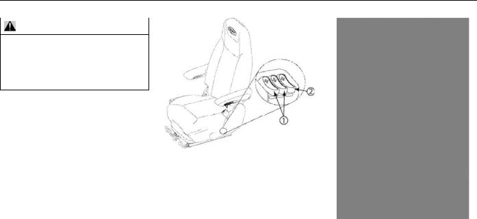
1. Seat heater/cooler |
6. |
Recline adjustment |
|
2. Seat thigh support up/down |
7. |
Armrest angle adjustment |
|
3. Seat bottom angle adjustment |
*This is an optional feature and may vary |
||
|
|
depending on the vehicle. |
|
1-20 |
Y53-6047–2C |
(04/13) |
SEATS AND RESTRAINTS
|
|
1 |
WARNING! |
|
|
|
|
|
Donotdriveorridewithyourseatback in the reclined position. You could be injured by sliding under the seat belts in a collision. Failure to comply may result in death or personal injury.
Lumbar (and bolster support if |
|
|
available) are provided for superior |
|
|
support to the back during operation. |
|
|
Lower support is standard and the |
|
|
optional functions include upper |
|
|
lumbar and bolster functions. Pressing |
1. Lower and Upper* lumbar adjustment |
|
on the “+” symbol of the button will |
||
2. Bolster* adjustment |
||
add support in the area. Pressing the |
* This is an optional feature and may vary |
|
opposite side of the button will release |
depending on the vehicle. |
|
pressure and will reduce support in the |
The seats in this vehicle are equipped |
|
area. |
||
|
with a switch that locks out the fore-aft |
|
|
isolator function in the seat. When |
|
|
locked, the seat will not move back |
|
|
and forth. It will be rigidly fixed and |
|
|
only allowed to move up and down |
|
|
with the vehicle’s movements. |
(04/13) |
Y53-6047–2C |
1-21 |
SEATS AND RESTRAINTS
1 |
Passenger Seat Swivel (Optional) |
|
Safety Restraint Belts |
WARNING! |
This vehicle may be equipped with a swivel function on the passenger seat.
Do not use the swivel function while a
This function allows the passenger
passenger is in the seat and the vehi-
seat to rotate and face towards the
cle is in motion. The seat belt will not
inside of the cab.
provide proper protection if the passenger is not facing forward and the
WARNING!
vehicle is in an accident. Failure to
complymayresultindeathorpersonal Always ensure that the passenger injury.
seat is locked into the forward-facing position when the vehicle is in motion. Locking the swivel seat into the forward facing position maximizes visibility to the surrounding area. Failure to comply creates a safety hazard that
may result in death or personal injury.
Safety belts have proven to be the single most effective means available for reducing the potential for either death or personal injury in motor vehicle accidents. Unbelted riders could be thrown into the windshield or other parts of the cab or could be thrown out of the cab. They could strike another person. Injuries can be
1-22 |
Y53-6047–2C |
(04/13) |
 Loading...