

Page 1

MODEL 330
OPERATOR’S MANUAL
Page 2

California
Proposition 65 Warning
Diesel engine exhaust and some of its constituents are known
to the State of California to cause cancer, birth defects, and
other reproductive harm.
Other materials in this vehicle are also known to the State of
California to cause cancer, birth defects or other reproductive
harm.
Battery posts, terminals, and related accessories contain
lead and lead compounds, chemicals known to the State of
California to cause cancer and rep roductive harm. Wash
hands after handling.
Page 3

Peterbilt Model 330
CONTENTS
Introduction
How to Use This Manual . . . . . . . . . . . . . . . . . . . . . . . 1
Safety Signals . . . . . . . . . . . . . . . . . . . . . . . . . . . . . . . . 1
Vehicle Safety . . . . . . . . . . . . . . . . . . . . . . . . . . . . . . . . 3
How to Find What You Want . . . . . . . . . . . . . . . . . . . . 3
A Special Word About Repairs . . . . . . . . . . . . . . . . . . . 4
Shop Manuals . . . . . . . . . . . . . . . . . . . . . . . . . . . . . . . . 4
Preventive Mai ntenance Section . . . . . . . . . . . . . . . . . 5
Additional Sources of Information . . . . . . . . . . . . . . . . . 5
Operating Instructions
Start–Up
Introduction . . . . . . . . . . . . . . . . . . . . . . . . . . . . . . . . . . 7
Door Lock and Keys . . . . . . . . . . . . . . . . . . . . . . . . . . . 7
Cab and Frame Access . . . . . . . . . . . . . . . . . . . . . . . . 7
Hood Hold Downs and Tilt . . . . . . . . . . . . . . . . . . . . . . 9
Hood Safety Cable . . . . . . . . . . . . . . . . . . . . . . . . . . . . 10
Safe Vehicle Operation . . . . . . . . . . . . . . . . . . . . . . . . . 10
Vehicle Loading . . . . . . . . . . . . . . . . . . . . . . . . . . . . . . 11
Emergency Equipment . . . . . . . . . . . . . . . . . . . . . . . . . 12
Driver’s Check List . . . . . . . . . . . . . . . . . . . . . . . . . . . . 12
Model 330
Instruments and Controls
Introduction . . . . . . . . . . . . . . . . . . . . . . . . . . . . . . . . . 17
Warning Lights and Buzzer . . . . . . . . . . . . . . . . . . . . . 17
Self Test . . . . . . . . . . . . . . . . . . . . . . . . . . . . . . . . . . . 19
Speedometer and Odomet er . . . . . . . . . . . . . . . . . . . . 20
Tachometer . . . . . . . . . . . . . . . . . . . . . . . . . . . . . . . . . 21
Coolant (Water) Tem perature Gauge . . . . . . . . . . . . . 22
Engine Oil Pressure Gauge . . . . . . . . . . . . . . . . . . . . . 24
Dual Air Pressure Gauge (Air Reservoir) . . . . . . . . . . 25
Fuel Gauge . . . . . . . . . . . . . . . . . . . . . . . . . . . . . . . . . 27
Voltmeter (option) . . . . . . . . . . . . . . . . . . . . . . . . . . . . 28
Transmission Temperature Gauge (option) . . . . . . . . . 28
Air Filter Restriction Indicator (option) . . . . . . . . . . . . . 29
Headlight Switch . . . . . . . . . . . . . . . . . . . . . . . . . . . . . 29
Dayti me Running Lig h ts (option) . . . . . . . . . . . . . . . . . 30
Panel Lights . . . . . . . . . . . . . . . . . . . . . . . . . . . . . . . . . 30
ID and Clearance Lights . . . . . . . . . . . . . . . . . . . . . . . 30
Windshield Wipers/Washer . . . . . . . . . . . . . . . . . . . . . 31
Ignition Key Switch . . . . . . . . . . . . . . . . . . . . . . . . . . . 32
Parking Brake . . . . . . . . . . . . . . . . . . . . . . . . . . . . . . . 33
Cruise Control Switch . . . . . . . . . . . . . . . . . . . . . . . . . 36
Hand Throttle Control . . . . . . . . . . . . . . . . . . . . . . . . . 36
Heating and Air Conditioning
Introduction . . . . . . . . . . . . . . . . . . . . . . . . . . . . . . . . . 37
– i –
Page 4

Controls . . . . . . . . . . . . . . . . . . . . . . . . . . . . . . . . . . . . 38
Heating . . . . . . . . . . . . . . . . . . . . . . . . . . . . . . . . . . . . . 39
Defogging . . . . . . . . . . . . . . . . . . . . . . . . . . . . . . . . . . . 39
Cooling . . . . . . . . . . . . . . . . . . . . . . . . . . . . . . . . . . . . . 39
Accessories
Radio . . . . . . . . . . . . . . . . . . . . . . . . . . . . . . . . . . . . . . 41
Cigarette Lighter . . . . . . . . . . . . . . . . . . . . . . . . . . . . . . 41
Ashtray . . . . . . . . . . . . . . . . . . . . . . . . . . . . . . . . . . . . . 41
Air Operated Horn (Option) . . . . . . . . . . . . . . . . . . . . . 41
Glove Compartment . . . . . . . . . . . . . . . . . . . . . . . . . . . 42
Dome Light . . . . . . . . . . . . . . . . . . . . . . . . . . . . . . . . . . 42
Seats
Introduction . . . . . . . . . . . . . . . . . . . . . . . . . . . . . . . . . . 43
Seat Adjustment . . . . . . . . . . . . . . . . . . . . . . . . . . . . . . 43
Safety Restraint Belts . . . . . . . . . . . . . . . . . . . . . . . . . . 44
Tether Belts . . . . . . . . . . . . . . . . . . . . . . . . . . . . . . . . . 48
Komfort–Lok® Latch . . . . . . . . . . . . . . . . . . . . . . . . . . . 49
During Pregnancy . . . . . . . . . . . . . . . . . . . . . . . . . . . . . 50
Passengers . . . . . . . . . . . . . . . . . . . . . . . . . . . . . . . . . 50
Belt Damage and Repair . . . . . . . . . . . . . . . . . . . . . . . 50
Steering Column and Mirrors
Introduction . . . . . . . . . . . . . . . . . . . . . . . . . . . . . . . . . . 51
Turn Signal/High Beam Swit ch . . . . . . . . . . . . . . . . . . . 51
Emergency Flasher Switch . . . . . . . . . . . . . . . . . . . . . . 52
Trailer Brake Hand Valve . . . . . . . . . . . . . . . . . . . . . . . 52
Adjustable Steering Column (option) . . . . . . . . . . . . . . 53
Horn . . . . . . . . . . . . . . . . . . . . . . . . . . . . . . . . . . . . . . . 53
Mirrors . . . . . . . . . . . . . . . . . . . . . . . . . . . . . . . . . . . . . 53
Operating the Engine
Introduction . . . . . . . . . . . . . . . . . . . . . . . . . . . . . . . . . 55
Starting Procedure — Normal Temperature . . . . . . . . 55
Starting Procedure — Cold Weather . . . . . . . . . . . . . . 57
Engine Warm–Up and Idling . . . . . . . . . . . . . . . . . . . . 59
Idling the Engine . . . . . . . . . . . . . . . . . . . . . . . . . . . . . 60
Engine Fan Switch (Option) . . . . . . . . . . . . . . . . . . . . 61
Cruise Control (Option) . . . . . . . . . . . . . . . . . . . . . . . . 62
Engine Shutdown System (Option) . . . . . . . . . . . . . . . 63
Operating the Transmission
Introduction . . . . . . . . . . . . . . . . . . . . . . . . . . . . . . . . . 64
Operating Manual Transmissions . . . . . . . . . . . . . . . . 64
Putting the Vehicle in Motion . . . . . . . . . . . . . . . . . . . . 65
More Transmission Tips . . . . . . . . . . . . . . . . . . . . . . . 67
Operating Automat ic Transmissions . . . . . . . . . . . . . . 68
Using the Brake System
Introduction . . . . . . . . . . . . . . . . . . . . . . . . . . . . . . . . . 70
Using the Parking Brake . . . . . . . . . . . . . . . . . . . . . . . 72
Tractor and Trailer Air Supply Valve . . . . . . . . . . . . . . 74
Brake Safety and Emergency . . . . . . . . . . . . . . . . . . . 76
Anti-Lock Braking System . . . . . . . . . . . . . . . . . . . . . . 79
Trailer Brake Hand Valve . . . . . . . . . . . . . . . . . . . . . . 81
Driving Bobtail or Wit h an Unloaded Trailer . . . . . . . . 82
Engine Retarder (option) . . . . . . . . . . . . . . . . . . . . . . . 83
Brake Components . . . . . . . . . . . . . . . . . . . . . . . . . . . 84
Hydraulic Brakes . . . . . . . . . . . . . . . . . . . . . . . . . . . . . 86
Operating the Rear/Drive Axle
Introduction . . . . . . . . . . . . . . . . . . . . . . . . . . . . . . . . . 93
– ii –
Model 330
Page 5

Interaxle Differential Lock . . . . . . . . . . . . . . . . . . . . . . . 93
More Driving Tips and Techniques
Introduction . . . . . . . . . . . . . . . . . . . . . . . . . . . . . . . . . . 96
Coasting . . . . . . . . . . . . . . . . . . . . . . . . . . . . . . . . . . . . 96
Descending a Grade . . . . . . . . . . . . . . . . . . . . . . . . . . . 96
Economical Drivin g . . . . . . . . . . . . . . . . . . . . . . . . . . . . 97
Safe Driving . . . . . . . . . . . . . . . . . . . . . . . . . . . . . . . . . 100
Air Suspension Height/Air Pressure . . . . . . . . . . . . . . . 101
Fifth Wheel . . . . . . . . . . . . . . . . . . . . . . . . . . . . . . . . . . 105
Vehicle Recovery and Spring Brakes
Introduction . . . . . . . . . . . . . . . . . . . . . . . . . . . . . . . . . . 108
Vehicle Recovery Guidelines . . . . . . . . . . . . . . . . . . . . 109
Spring Brakes — Manual Rele ase . . . . . . . . . . . . . . . . 110
Freeing the Vehicle from Sand,
Mud, Snow and Ice . . . . . . . . . . . . . . . . . . . . . . . . . 112
Shut–Down
Introduction . . . . . . . . . . . . . . . . . . . . . . . . . . . . . . . . . . 114
Final Stopping Procedures . . . . . . . . . . . . . . . . . . . . . . 114
Before Stopping the Engine . . . . . . . . . . . . . . . . . . . . . 115
Refuelling . . . . . . . . . . . . . . . . . . . . . . . . . . . . . . . . . . . 115
Preventive Maintenance
Introduction
Safety Precautions . . . . . . . . . . . . . . . . . . . . . . . . . . . . 117
Environmental Protection and Material Hazards . . . . . 118
How to Order Parts . . . . . . . . . . . . . . . . . . . . . . . . . . . . 119
Maintenance Schedule and Lubr ication
Introduction . . . . . . . . . . . . . . . . . . . . . . . . . . . . . . . . . 120
Preventive Mai ntenance Intervals and Schedule . . . . 120
Lubrication Specifications . . . . . . . . . . . . . . . . . . . . . . 134
Oil Reservoirs . . . . . . . . . . . . . . . . . . . . . . . . . . . . . . . 136
Lubrication Chart . . . . . . . . . . . . . . . . . . . . . . . . . . . . . 136
Engine Maintenance
Engine Lubrication . . . . . . . . . . . . . . . . . . . . . . . . . . . . 139
Fuel System . . . . . . . . . . . . . . . . . . . . . . . . . . . . . . . . . 140
Accessory Drive Belts . . . . . . . . . . . . . . . . . . . . . . . . . 142
Engine Fan . . . . . . . . . . . . . . . . . . . . . . . . . . . . . . . . . 143
Exhaust System . . . . . . . . . . . . . . . . . . . . . . . . . . . . . . 144
Cooling System
Introduction . . . . . . . . . . . . . . . . . . . . . . . . . . . . . . . . . 145
Radiator and Hose Clamps . . . . . . . . . . . . . . . . . . . . . 145
Topping Up . . . . . . . . . . . . . . . . . . . . . . . . . . . . . . . . . 145
Adding Coolant . . . . . . . . . . . . . . . . . . . . . . . . . . . . . . 148
Change and Refilling . . . . . . . . . . . . . . . . . . . . . . . . . . 150
Engine (Block) Heater (option) . . . . . . . . . . . . . . . . . . 151
Brake System
Introduction . . . . . . . . . . . . . . . . . . . . . . . . . . . . . . . . . 153
Lubrication . . . . . . . . . . . . . . . . . . . . . . . . . . . . . . . . . . 154
Checks and Adjustments . . . . . . . . . . . . . . . . . . . . . . . 154
Hydraulic Brake System . . . . . . . . . . . . . . . . . . . . . . . 157
Anti–Lock Braking System (ABS) . . . . . . . . . . . . . . . . 161
Air System
Introduction . . . . . . . . . . . . . . . . . . . . . . . . . . . . . . . . . 163
Scheduled Maintenance . . . . . . . . . . . . . . . . . . . . . . . 164
Model 330
– iii –
Page 6

Air Tanks . . . . . . . . . . . . . . . . . . . . . . . . . . . . . . . . . . . 165
Dual Air Gauge and Air Leaks . . . . . . . . . . . . . . . . . . . 166
Air Compressor . . . . . . . . . . . . . . . . . . . . . . . . . . . . . . 167
Air Dryer . . . . . . . . . . . . . . . . . . . . . . . . . . . . . . . . . . . . 168
Air Intake System . . . . . . . . . . . . . . . . . . . . . . . . . . . . . 169
Air Filter Replacement . . . . . . . . . . . . . . . . . . . . . . . . . 170
Tires and Wheels
Introduction . . . . . . . . . . . . . . . . . . . . . . . . . . . . . . . . . . 172
General Safety Requirements . . . . . . . . . . . . . . . . . . . 172
Tire Inspection and Replacement . . . . . . . . . . . . . . . . . 173
Tire Inflati on and Loading . . . . . . . . . . . . . . . . . . . . . . . 173
Wheel Mounting and Fastening . . . . . . . . . . . . . . . . . . 176
Disc Wheels . . . . . . . . . . . . . . . . . . . . . . . . . . . . . . . . . 178
Demounted Rims . . . . . . . . . . . . . . . . . . . . . . . . . . . . . 179
Comparing Hub Piloted and Ball Seat Parts . . . . . . . . 179
Tire Replacement . . . . . . . . . . . . . . . . . . . . . . . . . . . . . 181
Matching Tires . . . . . . . . . . . . . . . . . . . . . . . . . . . . . . . 181
Wheel and Tire Replace me nt fo r Trucks with Hydraulic
Brakes . . . . . . . . . . . . . . . . . . . . . . . . . . . . . . . . . . . 182
Heater and Air Conditioner
Introduction . . . . . . . . . . . . . . . . . . . . . . . . . . . . . . . . . . 183
Special Precautions . . . . . . . . . . . . . . . . . . . . . . . . . . . 183
Heater . . . . . . . . . . . . . . . . . . . . . . . . . . . . . . . . . . . . . . 183
Air Conditioner . . . . . . . . . . . . . . . . . . . . . . . . . . . . . . . 184
Electrical System
Location Of Fuses . . . . . . . . . . . . . . . . . . . . . . . . . . . . 185
Adding Electrical Options . . . . . . . . . . . . . . . . . . . . . . . 185
Truck-Body Connection . . . . . . . . . . . . . . . . . . . . . . . . 185
Batteries . . . . . . . . . . . . . . . . . . . . . . . . . . . . . . . . . . . 185
Battery Care . . . . . . . . . . . . . . . . . . . . . . . . . . . . . . . . 187
Jump Starting Vehicles . . . . . . . . . . . . . . . . . . . . . . . . 187
Battery Charging . . . . . . . . . . . . . . . . . . . . . . . . . . . . . 191
Bulb Replacement . . . . . . . . . . . . . . . . . . . . . . . . . . . . 193
Electrical and Al ter nator Precautions . . . . . . . . . . . . . 194
Cab Maintenance
Exterior Maintenance . . . . . . . . . . . . . . . . . . . . . . . . . 195
Cleaning, Protection and Weather–Stripping . . . . . . . 196
Safety Restraint System — Inspection . . . . . . . . . . . . 198
Windshield Wiper/Washer . . . . . . . . . . . . . . . . . . . . . . 201
Washer Reservoir . . . . . . . . . . . . . . . . . . . . . . . . . . . . 201
Transmission and Clutch
Introduction . . . . . . . . . . . . . . . . . . . . . . . . . . . . . . . . . 202
All Transmissions . . . . . . . . . . . . . . . . . . . . . . . . . . . . 202
Manual Transmissions . . . . . . . . . . . . . . . . . . . . . . . . 202
Clutch System Introduction . . . . . . . . . . . . . . . . . . . . . 203
Clutch Adjustment — Normal Wear . . . . . . . . . . . . . . 204
Automatic Transmissions . . . . . . . . . . . . . . . . . . . . . . 205
Steering and Driveline
Power Steering . . . . . . . . . . . . . . . . . . . . . . . . . . . . . . 206
Fluid Level and Refil l . . . . . . . . . . . . . . . . . . . . . . . . . . 207
Steering Driveline . . . . . . . . . . . . . . . . . . . . . . . . . . . . 208
Driveshaft and U-Joints . . . . . . . . . . . . . . . . . . . . . . . . 208
Front Axle and Suspension
Inspection . . . . . . . . . . . . . . . . . . . . . . . . . . . . . . . . . . 209
Axle Lubrication . . . . . . . . . . . . . . . . . . . . . . . . . . . . . . 209
Suspension Lubri cation . . . . . . . . . . . . . . . . . . . . . . . . 210
– iv –
Model 330
Page 7

Torque . . . . . . . . . . . . . . . . . . . . . . . . . . . . . . . . . . . . . 211
Rear Axle and Suspension
General Maintenance . . . . . . . . . . . . . . . . . . . . . . . . . . 212
Visual Inspection . . . . . . . . . . . . . . . . . . . . . . . . . . . . . 212
Rear Axle Lubrication . . . . . . . . . . . . . . . . . . . . . . . . . . 213
Rear Suspension Fasteners . . . . . . . . . . . . . . . . . . . . . 215
Frame and Fifth Wheel
Introduction . . . . . . . . . . . . . . . . . . . . . . . . . . . . . . . . . . 218
Fifth Wheel Maintenance . . . . . . . . . . . . . . . . . . . . . . . 219
Sliding Fifth Wheel . . . . . . . . . . . . . . . . . . . . . . . . . . . . 219
Noise and Emission Control
Noise Emission Warranty . . . . . . . . . . . . . . . . . . . . . . 220
Inspection and Maintenance Instructions . . . . . . . . . . 221
Maintenance Log . . . . . . . . . . . . . . . . . . . . . . . . . . . . . 223
Consumer Information
and Vehicle Identification
Reporting Safety Defects . . . . . . . . . . . . . . . . . . . . . . . 226
Vehicle Identif ication . . . . . . . . . . . . . . . . . . . . . . . . . . 226
Complete Vehicle Certification Label . . . . . . . . . . . . . . 228
Incomplete Vehicle Certification Label . . . . . . . . . . . . 229
Component Identi fi cation . . . . . . . . . . . . . . . . . . . . . . . 230
Model 330
– v –
Page 8

LIST OF TABL ES
Table 1 Index of Gauges . . . . . . . . . . . . . . . . . . . . . . . . . . . . . . . . 17
Table 2 Recommended Maintenance Intervals . . . . . . . . . . . . . 121
Table 3 Maintenance Schedule . . . . . . . . . . . . . . . . . . . . . . . . . 124
Table 4 Lubricant Applications . . . . . . . . . . . . . . . . . . . . . . . . . . 135
Table 5 Recommended Lubrication Types . . . . . . . . . . . . . . . . . 137
Table 6 Radiator Hose Clamp Torque Values . . . . . . . . . . . . . . 145
Table 7 Cooling System Maintenance and Schedule . . . . . . . . . 147
Table 8 Antifreeze Protection — Ethylene Glycol . . . . . . . . . . . . 149
Table 9 Coolant Capacity . . . . . . . . . . . . . . . . . . . . . . . . . . . . . . 151
Table 10 Brake Adjuster Stroke . . . . . . . . . . . . . . . . . . . . . . . . . . 156
Table 11 Air System Scheduled Maintenance . . . . . . . . . . . . . . . .164
Table 12 Effect of Load Pressure on Tire Life . . . . . . . . . . . . . . . .175
Table 13 Wheel Cap Nut Torque . . . . . . . . . . . . . . . . . . . . . . . . . .177
Table 14 Comparing Hub-piloted and Ball-seat Wheels . . . . . . . . .180
Table 15 Acceptable Rev per Mile . . . . . . . . . . . . . . . . . . . . . . . . .182
Table 16 Transmission Lubr ication — Manu al transmissions . . . .203
Table 17 Transmission Lubrication — Automatic transmissions . .205
Table 18 Drive Axle Lubrication . . . . . . . . . . . . . . . . . . . . . . . . . . .214
Table 19 Maintenance Log . . . . . . . . . . . . . . . . . . . . . . . . . . . . . . .223
Table 20 Model Year Letter Designations . . . . . . . . . . . . . . . . . . .227
– vi –
Model 330
Page 9

Introduction
INTRODUCTION
How to Use This Manual
This Operator’s Manual contains useful information for the
safe and efficient operation of your Model 330, Medium–duty
vehicle . It also prov ides inf ormation on maintaining y our v ehicle in the best condition, with an outline for performing safety
checks and basic preventive maintenance inspections.
We have tried to pr esent the inform ation you'll need to lear n
about your vehicle's functions, controls, and operation as
clearly as poss ible. We h ope you'll fin d this m anual ea sy t o
use. There will be t imes when you need to take this m anual
out of your Peterbilt vehicle. When you do, please be sure to
return it to the cab when you are finished using it. That way it
will be there when y ou need it th e ne xt time or when you pass
the vehicle on to the next user.
Your Model 330 ma y not have all the featur es or opti ons mentioned in this manua l. T herefore, you sh ould pay c aref ul
attention to the instructions that pertain to just your vehicle . In
Model 330 PB1318 3/01
addition, if y our v ehicl e is equipped w ith s pecial equipment or
options not discusse d in this m anual, consult your dea ler o r
the manufacturer of the equipment.
All information contained i n this manual is based on the latest
production information available at the time of publication.
Peterbilt Motors Comp any re serves the right to make
changes at any time without notice.
Safety Signals
A number of alerting messages are in this manual. Please
read and follow them. T hey are there for your protection and
inform ation. These messages can help you avoid injury to
yourself and your passengers, and can help prevent costly
damage to the vehicle.
Key symbols and “signal words” are used to indicate what
kind of message is going to follow. Pay special attention to
instructions prefaced by symbols and the signal words
“WARNING”, “CAUTION”, and “NOTE”. Please do not ignore
any of these alerts.
– 1 –
Page 10

Introduction
WARNI NG
When you see this word, the message that foll ows is
especially vital. It signals a potentially hazardous
situation which, if not avoided, could result in death
or serious injury. This message will tell you what the
hazard is, what can happen if you don’t heed the
warning, and how to avoid it.
WARNING! Never carry additional fuel containers in the vehicle. Such containers, full or empty ,
may leak, explode or cause a fire in the event of
a collision.
CAUTION
Signals a potentially hazardous situation which, if
not avoided, could result in minor or moderate injury
or damage to the vehicle.
CAUTION: Continuin g to op erate your vehicle
with i nsu ffici ent oil pr es sure w ill ca us e s er iou s
engine damage.
Example:
Example:
NOTE
Provides general information: for example, the note
could warn you on ho w to avoid damaging your vehicle or how to drive the vehicle more efficiently.
Example:
NOTE: Pumping the accelerator will not assist in
starting the engine.
Please take the time to read these messages when
you see them, and remember:
WARNING!
Something that could injure you seriously.
CAUTION:
Something that could cause injury to you or your vehicle.
NOTE:
Useful information.
– 2 –
PB1318 3/01 Model 330
Page 11

Introduction
Vehicle Safety
Make sure your Model 330 is in top working condition before
heading out on the road—it is the
do so. Inspect the vehicle according to the
List”, page 12
.
responsible
WARNING! Do not drink and drive. Y our refle xes,
perceptions, and judgment can be affected by
even a small amount of alcoh ol. You could have
a serious—or even fatal accident—if you drive
after drinking. Please do not drink and drive or
ride with a driver who has been drinking .
Please remember, this manual is not a training manual. It cannot tell you everything you need to know about driving your Peterbilt vehicle. For tha t you nee d a go od train ing
program or truck driving school. If you have not been trained,
get the proper training bef ore y ou driv e. Only qualified drivers
should drive this vehicle.
Every new Peterbilt v ehi cle is designed to conform to all Federal Motor Vehicle Safety Standards applicable at the time of
manufacture. However, even with these safety features, continued safe and reliable operation depends greatly upon regular vehicle main tenanc e. The vehic le must be o perate d
within the range of its mechanical capabilities and the limits
driver's duty to
“Driver's Check
of its load ratings. (S ee the tire and rim weight ratings information on the Vehicle Certification Label on the driver’s door
frame.) This vehicle is not approved for off-road operation.
How to Find What You Want
There are several tools built into this manual to help you find
what you need quickly and easily. First is the Contents.
Located at the front of the manual, this l ists the main subj ects
covered and gives p age num ber s w here you ca n f ind the se
subjects. Use the Contents to find information on a large sub-
ject like “Operating the Transmission.”
Cross-references als o help y ou get the information you need.
If some other part of the manual contains fur ther information
on the subject you are reading about, a cross-reference will
refer you to another page, for example: “See
more information on Safety Restraint Belts.”
Finally, you will find a helpful Index at the back of the manual,
listing subjects alphabetically. For example, if you want information on brakes, just look under “Brakes” in the Index. You
will find the pages where brakes or related topics are discussed.
page 44
, for
Model 330 PB1318 3/01
– 3 –
Page 12

Introduction
A Special Word About Repairs
This is not a repair or workshop manual. Your Peterbilt
Dealer’s Service Center is the best place to have your Model
330 repaired. You can find Peterbilt dealers all over the country wit h the equ ipmen t and train ed per sonne l to quickly ge t
you back on the road—and to keep you there.
Your Model 330 is a complex machine. Anyone attempting
repairs on it needs good mechanical training, proper specifications, and proper tools. If you are sure you meet these
qualific ations, the n you can prob ably per form some r epairs
yourself. But if you are no t an exper i ence d m echa nic, or d o
not have the right equipment or training, please leave the
repairs to an authorized service facility. They are the ones
equipped to do the job safely and correctly.
WARNING! Do not attempt repair work without
sufficient training, service manuals, and the
proper tools. Yo u could be injur ed, or you could
make your vehicle unsafe. Do only those tasks
you are fully qualified to do.
Shop Ma nuals
If you do decide to do complex r epair work, you will need the
Medium Duty Maintenance Manual. It contains service procedures, parts information, and supporting material on major
components in your vehicle, such as Suspensions, Drivelines, Axles, and the Heater/Air Conditioner.
Listed below are manuals available from your Peterbilt
Dealer. (There is a charge for these manuals.) Please provide the Chassis Serial Number when ordering, to be sure
you get the correct manuals for your vehicle.
Medium Duty Maintenance Manual
detailed ser vice procedu res specific ally comp iled for the
components on your vehi cle , including: el ectrical inf ormation,
maintenance, disassembly, assembly, repairs, overhaul, and
troubleshooting procedures. The information contained in
this manual is the same used by Peterbilt dealers.
Medium Duty Master Parts Catalog
parts lists with drawings and exploded views for MODEL 330
series vehicles.
. This manual inc lud es
. Contains illustrated
– 4 –
PB1318 3/01 Model 330
Page 13

Introduction
Medium Duty Body Builders’ Manual. Contains general
guidelines on mecha nical and ele ctrical modificatio ns
required by your dealer to add bodies, accessories, and special equipment to straight-truck configurations.
WARNING! Modifying your vehicle can make it
unsafe. Some mo difications can affect your
vehicle ’s electr ical s ystem , st abilit y, or other
impor tant function s. Before mo difying your
vehicle, check with your dealer to make sure it
can be done safely.
Preventive Maintenanc e Section
The Preventive Maintenance section (pages
this manual contains general service information for the operator, such as: lubrication points, making adjustments, and
other help fu l se r vice in forma tion . This is s umm ary inform ation only, used for gener al maintenance of major components
installed on your Model 330. For detailed service information
see your Medium Duty Maintenance Manual.
When it comes time for major service work, your Peterbilt
Dealer or Authorized Service Center will need vehicle and
component information. To help you gather this vehicle infor-
117
–
230
) in
mation, see
cation” on page 2 26
identification and provides space to record model a nd ser ial
numbers of major components installed on your vehicle.
“Consum er Informa tion and Vehicle Identifi-
. This section explains vehicle
Additional Sources of Information
Installed Equipment — Operator's Manuals
Major component suppliers to Peterbilt also supply operation
manuals specific to their products. Additional manuals and
other piec es of litera ture are inc lude d in th e g love compa r tment literature set. Look for information on products such as
the engine, driver’s seat, transmission, axles, tires, and r adi o .
If you are missing these pieces of literature, ask your P eterbilt
Dealer for copies.
Tru ck Driv e r’s Hand book
Your set of glove compartment literature also contains a copy
of the
Truck D river’s Ha ndb oo k
Trucking Association (ATA). Refer to it for important information on driving your Model 330.
, publish ed by t he A me rica n
Model 330 PB1318 3/01
– 5 –
Page 14

Introduction
Other Sources
Another place to learn more about trucking is from local truck
driving schools. Contact one near you to learn about courses
they offer.
Federal and s tate agencies such as the department of l icensing also have information you can ask for. The Inte rstate
Commerce Commission can give you infor mation about regulations governing transportation across state lines. Regulations that differ from state to state can be found at various
agencies in state governments.
– 6 –
PB1318 3/01 Model 330
Page 15

Operating Instructions Start–Up
OPERATING INSTRUCTIONS
START–UP
Introduction
The following section covers star t -up proced ure s for getti ng
your Model 330 ready for the road.
Door Lock and Keys
Doors can be locked from the inside by using the lock button.
Close the door then push the button down to lock. Doors
automat ica lly unlo ck wh en you open t he m fr om insi de, an d
can be locked from the outside with the key only.
As standard equipment, two keys are provided for the doors
and ignition. When necessary, additional locks and keys are
provided for storage compartments.
Model 330 PB1318 3/01
To lock or unlock the doors from outside the cab:
• Insert the key in the door lock.
• Turn the key toward the rear door frame to lock; forward
Cab and Frame Access
The following cab and frame entry/exit procedur e recommendations were prepared with personal saf ety f or emost in mind.
WARNING! To help lessen the chance and/or
severity of pers onal in jury in case of an acc ident, always lock the doors while driving. Along
with using the lap s houl der belt s prope rly, locking the doors helps prevent occupants from
being thrown from the vehicle.
to unlock.
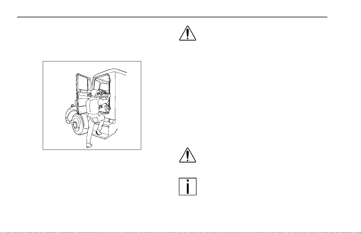
WARNING! Do not jump out of the cab or get into
the cab without proper caution. You could slip or
fall, possibly suffering a serious injury. You
could slip and fall if the steps are wet or icy, or if
you step in fuel, oil, or grease.
– 7 –
Page 16
Start–Up Operating Instructions
To help avoid personal injury due to a slip or fall:
• Use three points of contact (two feet, one hand or one
foot, two hands) to g rip the steps or handholds whene ver
possible and look where you are going.
02611
• Use even more care when steps and handholds (or footwear) are wet, coated with ice, snow, mud, oil, fuel, or
grease.
WARNING! Do not step on vehicle components
without antiskid sur faces or use component s
not designed for entry-and-exit use. You could
fall and injure yourself if you step onto a slippery
surface. For example:
• Do not step onto the surface of a fuel tank. A fuel
tank is not a step. The tank surface can get very slippery, and you might not be able to prevent a fall. Use
only the steps and handholds provided, not chain
hooks, quarter fenders, etc.
• Do not climb onto and off the deck p late—use steps
and grab han dle prov ided. If there is no deck pla te,
or if proper steps and grab handles are not provided,
do not climb onto the area behind the cab.
• Keep steps clean. Clean any fuel, oil, or grease off
the ste ps b efore enter ing the cab or acce ssi ng th e
deck plate.
WARNING! Always reinstall the battery compartment cover (step) before entering the cab. With out the battery cover you could slip and fall,
resulting in possible injury to yourself.
NOTE: Any alteration (adding bulkheads, headache
racks, tool boxes, etc.) behind the cab that affects
the utilization of grab handles, deck plates, or frame
access steps installed by Peterbilt should comply
with Federal Motor Carr ier Safety Regulation 399.
– 8 –
PB1318 3/01 Model 330
Page 17
Operating Instructions Start–Up
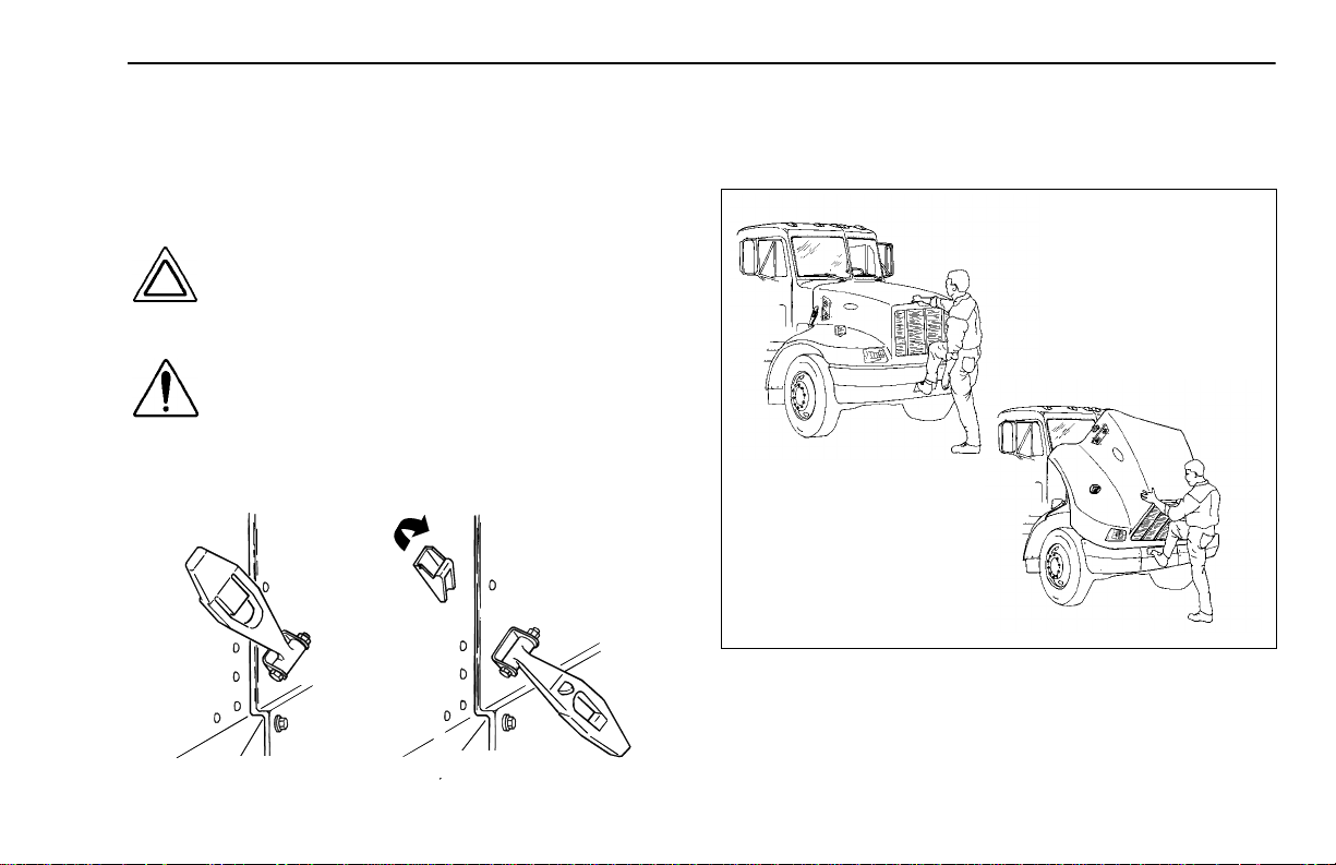
Hood Hold Downs and Tilt
The hood is locked in its closed position by an external latch
on each side. The se latc hes ser ve as ho ld downs an d keep
the hood from opening unexpectedly.
CAUTION: If you do not latch the hood securely,
it could open during operation and cause vehicle dam age. Be su r e t o la tch t he hood s ecu re ly
before moving the vehicle.
WARNING! A pivoting hood could hurt someone
or be dam aged itself. Before open ing or closing
the hood, be sure there are no people or objects
in the way.
To open the hood, unlatch both of the hood hold downs.
02597
Put one hand on the hood (just above the Peterbilt emblem),
one foot on the bumper, and one foot on the ground. Tilt the
hood forward.
02609-1, -2
LATCHED
UNLATCHED
Model 330 PB1318 3/01
– 9 –
Page 18
Start–Up Operating Instructions
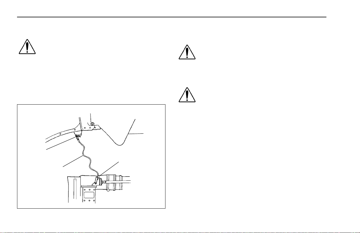
Hood Safety Cable
WARNING! If the hood falls, anyone under it
could be inju red. Always attach the safety cable
to keep your hood open any time anyone gets
under the hood for any reason.
• Never work under the hood unless the hood safety
cable is attached.
To attach the safety cable: The cable is on the driver’s side of
the radiator. Attach it to the hook on the hood.
HOOD IN
OPEN
POSITION
HOOK
SAFETY CABLE
CABLE
SECURED TO
RADIATOR
02610
To close the hood, you must first release the h ood safety
cable.
WARNING! Before closing the hood, be sure the
area is clear—no pe ople or objects are in the
way.
After lowering the hood, latch the hood closed w ith the h old
downs.
WARNING! If the hood is not latched securely, it
could open during operation and cause an accident. Be sure the hood is latched securely
before moving the vehicle.
Safe Vehicle Operation
For your safety, as well as those around you, be a responsible driver:
• If you drink, do not drive.
• Do not drive if y ou ar e t ired, ill, or under emotional stress.
Much has gone into the manufacturing of your Model 330,
including advanced engineering techniques, rigid quality control, and dem and ing in spec tio ns. The se m anu factur ing p ro cesses will be enhanced by you—the safe driver—who:
– 10 –
PB1318 3/01 Model 330
Page 19

Operating Instructions Start–Up
• knows and understands how to operate the vehicle and
all its controls
• maintains the vehicle properly
• uses driving skills wisely
For more information, re fer to De par tme nt o f Transportation
Regulation 392.7, which states that interstate commercial
motor vehicles are not to be dr iven unless the driver is sur e
that certain parts and accessories are in working order.
WARNING! Do not drink and drive. Y our refle xes,
perceptions, and judgment can be affected by
even a small amount of alcoh ol. You could have
a serious—even fatal—accident if you drive after
drinking. Please do not drink and drive or ride
with a driver who’s been drinking.
• The use of alcohol, dru gs, and certain medications
will seriously impair perception, reactions, and driving ability. These circumstances can substantially
increase the risk of an acc iden t and ser ious p ersonal injury.
Vehicle Loading
Compare your vehicle’s load capacity wit h the total load you
are carrying. If ad justments ne ed to be made, m ake them—
do not drive an overloaded vehicle. I f you are overloaded or
your load has shifted, your vehicle may be unsafe to drive.
WARNING! Do not exceed the specified load rating. Ove rload ing can res ult in loss of v ehicle
control and serious persona l inju ry, either by
causing component failures or by affecting vehicle handling. Exceeding load ratings can also
shorten the service life of the vehicle.
• The components of your vehicle are designed to provide satisfacto ry ser v ice if t he v ehicle is no t l oade d
in excess of either the gross vehicle weight rating
(GVWR), or the maximum front and rear gross axle
weight r atings (GAWRs). (Axle weight rati ngs are
listed on the driver's door edge.)
Here are some definitions of weight you should know:
GVWR:
MAXIMUM WEIGHT your vehicle is allowed to carry, including the weight of th e empty vehicle, loa ding plat form, oc cupants, fuel, an d any load. Never exceed the GVWR of your
vehicle.
is the Gross Vehicle Weight Rating. This is the
Model 330 PB1318 3/01
– 11 –
Page 20

Start–Up Operating Instructions
GCW: is the actual combined weight, or Gross Combination
Weight (GCW ), of your vehicl e and its l oad: tractor, plus
trailer(s), plus cargo.
GAWR:
weight that one axle is designed to transmit to the ground.
You will find this number listed on the driver’s door edge.
Load Distribution: be sure any load you carry is distributed
so that no axle has to support more than its GAWR.
is the Gross Axle Weight Rating. This is the total
WARNING! An unevenly distributed load or a
load too heavy over one axle can affect the braking and handling of your vehicle, which could
result in an accid ent . Even if your load i s un der
the legal limits, be sure it is distributed evenly.
Emergency Equipment
It is good practice to carry an emergency equipment kit in
your vehi cle . One da y, if you ha v e a roadside emergency, you
will be glad the following items are with you:
• window scraper
• snow brush
• container or bag of sand or salt
• emergency light
•small shovel
• first aid kit
• fire extinguisher
Driver’s Check List
To keep your Model 330 in top shape and maintain a high
level of safety for you, your passengers, and your load, make
a thorough inspection every day before you drive. You will
save maintenance time later, and the safety checks could
help prevent a serious accident. Please r emember, too, that
the Federal law requires a pre-trip inspection and so do commercial trucking companies.
You are not expected to become a professional mechanic.
The purpose of your inspections is to find anything that might
interfere with the safe and efficient transportation of yourself,
any passengers, and your load. If you do find som ething
wrong and cannot fix it yourself, have an Authorized Service
Center or qualified mechanic repair your vehicle right away.
– 12 –
PB1318 3/01 Model 330
Page 21

Operating Instructions Start–Up
The following op erat ions are to be perfor med by the driver.
Performing these checks and following the maintenance procedures in this manual will help k eep y our Model 330 running
properly.
Approaching Y our V ehicle
• Check the overall appearance and condition. Are windows, mirrors, and lights clean and unobstructed?
• Check beneath the vehicle. Are there signs of fuel, oil, or
water leaks?
• Check for damaged, loose, or missing parts. Are there
parts showing signs of excessive wear or lack of lubrication? Have a qualified mechanic examine any questionable items and repair them without delay.
• Check your load. Is it secured properly?
Daily Checks
NOTE: The following items (Engine Compartment, Chassis and Cab, and Prestart Checks)
should be checked daily, as a minimum. They
are in addition to, not in place of, federal motor
Carrier Safety Regulations. These regulations
may be purchased by writing to:
Superintendent of Documents
U.S. Government Printing Office
Washington, DC 20402
Engine Compartment Checks — Daily
1. Engine Fluid Levels—add more if necessary.
• Engine oil
• Coolant (check while engine is cold)
• Power steering fluid level
• If your truck has hydraulic brakes, check the fluid
level in the master cylinder reservoir. See
for more information.
2. Engine Belt—check tension and condition of belts. This
is important to ensure proper air compressor and engine
operation.
• Measure the belt tension at the longest span of the
belt. See
ing belt tension.
page 142
for further information on check-
page 158
NOTE: Deflection should be one belt thickness for each foot distance between the
pulley centers.
• If breaks or tears are found, the belt should be
replaced before operating the vehicle.
Model 330 PB1318 3/01
– 13 –
Page 22

Start–Up Operating Instructions
3. Fuel Filter/Water Separator Draining—check and drain.
Depending on the fuel storag e facility, more fr equent
draining may be required.
4. Windshield washer reservoir fluid level—fill if necessary.
5. Hood closed before entering cab. Is it latched properly?
Chassis and Cab Checks — Daily
Before entering the cab and operating the vehicle, check the
following equipment for proper maintenance:
1. Lights—do headlights, tur n signals, emergency flashers,
and exterior lamps function and are they clean and
adjusted properly?
2. Windows and Mirrors—are they clean and adjusted
properly?
3. Tires and Wheels—are they inflated properly? Are all
wheel cap nuts in place and torqued properly—tighten if
necessary. Check front wheel bearing oil levels. Inspect
all tires and wheels for damage—correct if found.
4. Suspension—check for loose or missing fasteners.
Check damage to springs or other suspension parts.
5. Brake Components—check lines, linkages, chambers,
and brake operation.
6. If your truck has hydraulic brakes, check:
• the brake system for leaks
• hydraulic lines for cracks or kinks
• calipers for leaks
7. Air System—are there leaks?
• Air Tanks—drain water from all air tanks. Make sure
the drai n cocks are clos ed. Th is pr oce dure is als o
required for air suspension tanks equipped with
automatic drain valves.
page 70
• See
System.”
8. Steps and Handholds—check for worn surfaces and
loose or missing fasteners.
9. Fluid Tanks—check underneath the vehicle for signs of
fluid leaks. If any are found, correct before operating the
vehicle.
10. Fuel Tank Caps—are they secure?
for further details on “Using the Brake
WARNING! Diesel fuel in the presence of an ignition source (such as a cigarette) could cause an
explosion. You could be seriously injured. A
mixture of gasoline or alcohol with diesel fuel
increases this risk of explosion.
• Do not remove a fuel tank cap near an open
flame.
• Use only the fuel and/or additives recommended
for your engine.
– 14 –
PB1318 3/01 Model 330
Page 23

Operating Instructions Start–Up
• See
page 115
11. Trailer Connections (Tractor)—are they secure and the
lines clear? If they are not being used, are they stored
properly?
• Is the trailer spare wheel secure and inflated?
• Is the landing gear up and the handle secured?
12. Check the fifth wheel. Is the kingpin locked?
• Is the sliding fifth wheel locked?
Prestart — Daily
1. Seat—adjust the seat for easy reach of controls.
2. If your vehicle is equipped with an adjustable steering
column, adjust the steering wheel to a comfortable position.
3. Mirrors—check and readjust mirrors if necessary.
4. Lights—turn ignition key to the IGN & ACC position and
check for warning lights and buzzer. Check operation of
turn signals and emergency lights.
5. Instruments—check all instruments.
6. Windshield—check operation of windshield wipers and
washers.
7. Horn—check operation of horn.
8. Check fire extinguisher charge and road emergency kit.
for more information.
9. Fuel—check fuel. Is there enough fuel?
10. Seat Belts—fasten and adjust safety restraint belts
Weekly Operations
1. Battery—check battery and terminals.
2. Wheel Cap Nuts—are they all in place and torqued properly—tighten if necessary. See
Torque,” Page 176
3. Other Controls and Wiring—check for condition and
adjustment.
4. Steering Components—check pitman arm, draglink, and
power steering hoses, etc., for loose, broken, or missing
parts.
5. Other Engine Compartment Checks
• Check condition and fasteni ng of engine belt, hoses,
clamps, and radiator.
• Check the air cleaner, muffler, and exhaust pipes.
Are they tight and secure?
• After Engine Warm-up
– Automatic Transmission—check fluid le vel in the
automatic transmission oil (if equipped).
.
“Wheel Cap Nut
Model 330 PB1318 3/01
– 15 –
Page 24
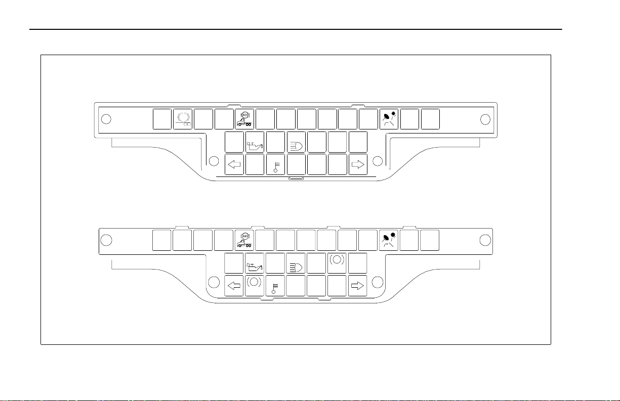
Start–Up Operating Instructions
14
5
6
2
15
8
7
1
3
02599A
4
10
9
11
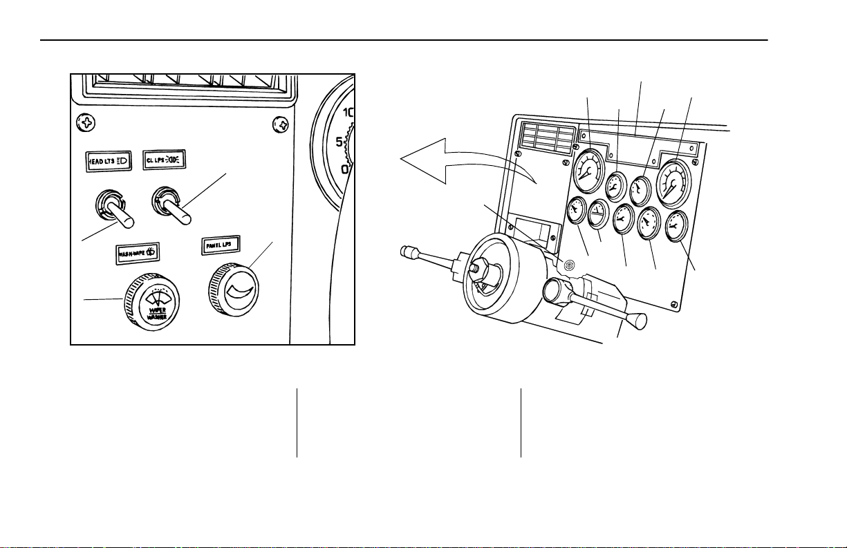
DASH INSTRUMENT PANEL
1 Headlight 6 Oil Pressure 11 Voltmeter (option)
2 Clearance Lights 7 Water Temperature 12 Air Pressure
3 Windshield Washer/Wiper 8 Speedometer 13 Transmission Temperature (option)
4 Panel Lights 9 Air Cleaner Restriction/Filter (option) 14 Warning Lamp Cluster
5 T achometer 10 Fuel 15 Ignition Switch
– 16 –
PB1318 3/01 Model 330
12
13
02595-1A
Page 25

Operating Instructions Instruments and Controls
INSTRUMENTS AND CONTROLS
Introduction
Your Model 330 dashboard is shown on the opposite page.
The dash includes standard gauges and switches. Your vehi-
cle may come with all or some of the switches and gauges
discussed here. The location of switches on the dash will
vary depending on the options ordered and how your vehicle
was configured.
For your convenience, all gauges and their corresponding
page numbers are listed her e, see
Refer to the page listed to lear n what each gauge does and
how it should be used.
“Index of Gaug es”
Instr u ment Index
Table 1 Index of Gauges
GAUGE REFERENCE PAGE
Tachom eter
Engine Oil Pressure
Engine Coolant Temperature
Speedometer
Air Cleaner Restriction (option)
Fuel Level
Voltmeter (option)
.
Air System Pressure
Transmission Temperature (option)
21
24
22
20
29
27
28
25
28
Warning Lights and Buzzer
Many vehicle systems are linked to the inst r umen ts on your
instrument panel. War ning lights (in each instrument) may
indicate something is wrong with one of the many vehicle
systems. Che ck the light s freq uently, and respond p rope rly
as soon as a light or buzzer comes on.
Model 330 PB1318 3/01
– 17 –
Page 26
Instruments and Controls Operating Instructions
WARNING LAMP MODULE
– 18 –
ENGINE
LOW
LOAD
HIGH
BEAM
FIFTH
WHEEL
LIGHT
STOP
ENGINE
CHECK
ENGINE
CONTROL
FAN
OIL
BRAKE
AIR
MIRROR
HEAT
WATER
WATER
ABS
VEHICLE WITH AIR BRAKES
ENGINE
LOAD
HIGH
BEAM
FIFTH
WHEE L
LIGHT
STOP
ENGINE
CHECK
ENGINE
CONTROL
FAN
LOW
OIL
BRAKE
MIR ROR
!
HEAT
WATER
WATER
VEHICLE WITH HYDR AU L IC BR AKES
PB1318 3/01 Model 330
CRUISE
CRUISE
DIFF
LOCK
PARK
SPOT
LIGHT
WAIT
TO
START
SPOT
RANGE
LIGHT
INHIBIT
P
CHECK
TRANS
Page 27

Operating Instructions Instruments and Controls
Self Test
When you t urn on your ig nitio n, th e follow ing war nin g li ghts
will turn on for 3 - 5 secon ds, a s a test to le t you know th ey
are working.
Diff Lock Trailer ABS
Water Temp Left Turn
Mirror Heat Load Light
Brake Air (or Brake *) High Beam
Fifth Wheel Right Turn
Oil Pressure Engine Fan
ABS Park *
* Vehicle with hydraulic brakes only
WARNING! Do not ign ore a wa rning light or
buzzer. These signals tell you something is
wrong with your vehicle. It could be a failure in an
important system, such as t he brakes, which could lead
to an accident. H ave the appropriate syste m checked
immediately.
The buzzer will sound continuously as long as:
• Engine temperature is above the specified range
• Air pressure to the service brakes is low
• Engine oil pressure is low
• There is a problem in the hydraulic brake system
If the buzzer sounds while driving, or if a light comes on, do
the following:
1. Slow down carefully.
2. Move a safe distance off the road and stop.
65
3. Set the parking brake. (See Pages
mission shifting and parking brake information.)
4. If the engine is overheating do not turn it off, see
22
; otherwise, for other conditions turn the engine OFF.
5. Turn on the emergency flasher and use other warning
devices to alert other motorists.
and 72 for trans-
page
Model 330 PB1318 3/01
– 19 –
Page 28
Instruments and Controls Operating Instructions
WARNING! Do not oper ate the vehicle if the
BRAKE warning lamp illuminates or the buzzer
sounds. The vehicle should not be operated until
the system is repaired. Failure to respond to a
brake warning (lamp or buzzer) could result in an
accident and/or severe injury.
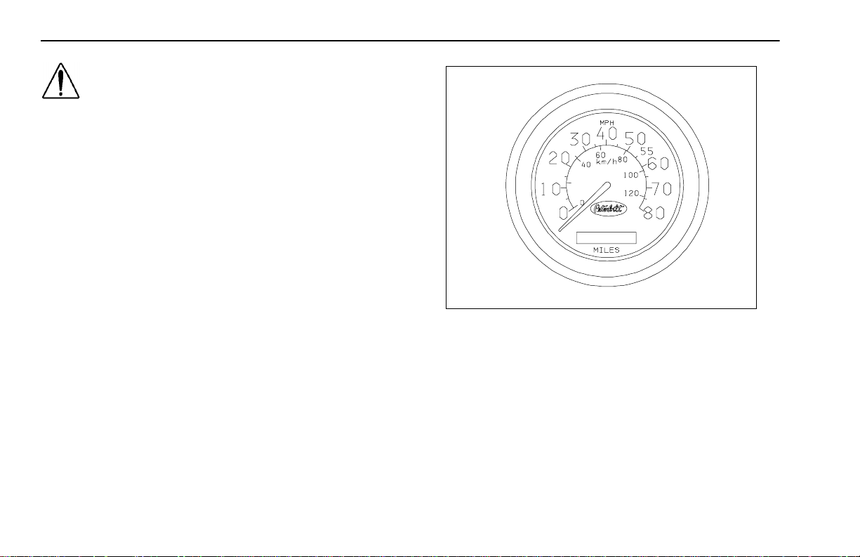
Speedometer and Odometer
The speedometer indicates the vehicle speed in miles per
hour (MPH) and in kilometers per hour (km/h).
The od om ete r r ecord s th e distan ce t raveled by t he vehic le,
either in miles or kilometers, dep ending on w hich unit is
installed in the vehicle.
Speedometer (MPH-km/h)
02587
– 20 –
PB1318 3/01 Model 330
Page 29
Operating Instructions Instruments and Controls
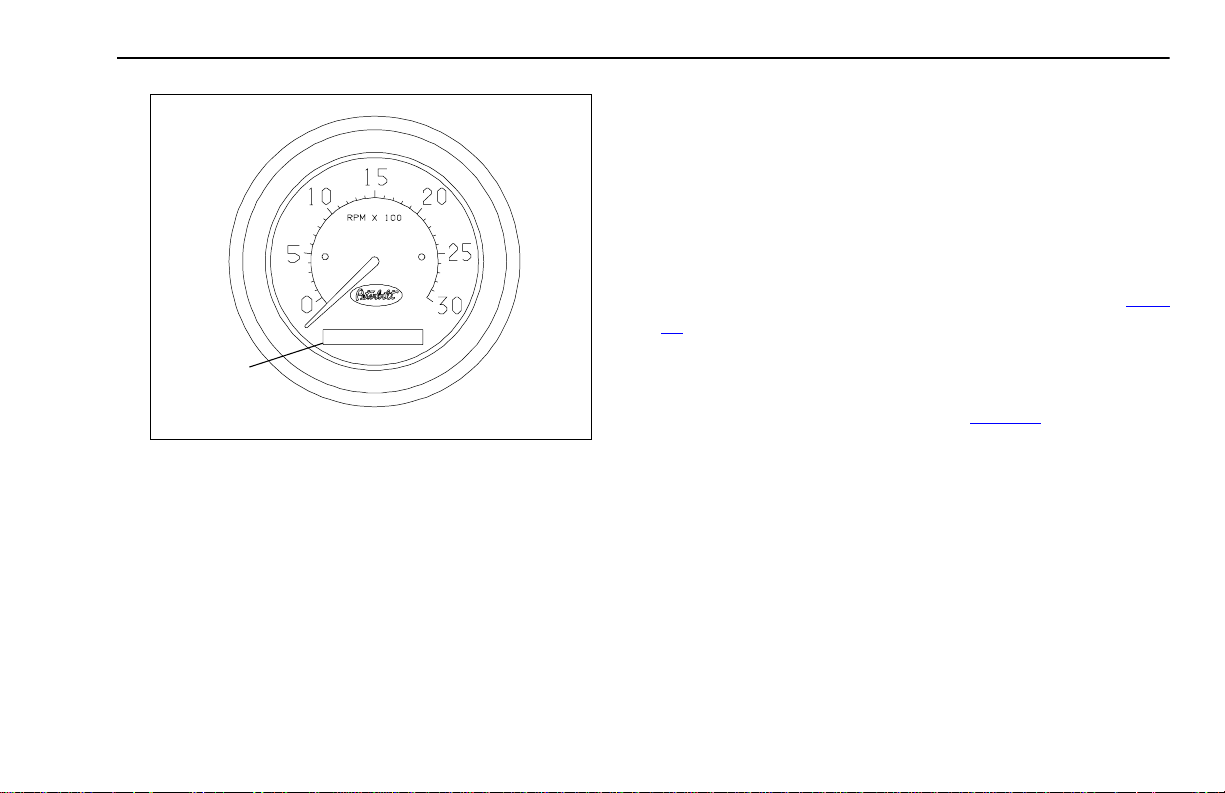
Tachometer
The vehicle’s tachometer measures the engine speed in rev-
olutions–per–minute (rpm). Watching the tachometer is
important to driving efficiently. It will let you match driving
speed and gear selection to the operating range of your
engine. If the en gin e sp eed g ets too h igh , you can s ele ct a
higher gear to lower the rpm's. If the engine speed drops too
page
HOURMETER
(OPTION)
Tachometer
02586
low, you can select a lower gear to raise the rpms. See
98
for further instructions on dri ving te chniques and usi ng the
tachometer.
• To avoid engine damage, do not let the pointer exceed
maximum governed speed. See
page 98
.
• When driving downhill, shift to a lower gear and use the
service brake, keeping the engine speed below the maximum governed speed.
The hour meter (option) records the time in hours the engine
is operating.
Model 330 PB1318 3/01
– 21 –
Page 30
Instruments and Controls Operating Instructions
02580
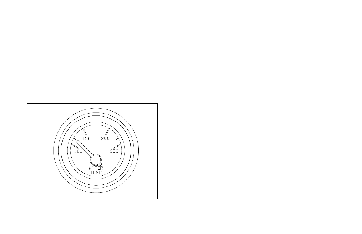
Coolant (Water) Temperature Gauge
The water temperature ga uge shows the te mperatur e of the
engine coolant. Under normal operating conditions the water
temperature g auge sho uld registe r between 16 5 a nd 205°F
(74 and 90°C). Under certain conditions, somewhat higher
temperatures may be acceptable. The maximum allowable
temperature is 210°F (99°C ) w ith the coolin g sys tem press urized, except for certain special engines. Check the engine
manual to be sure.
Water Temperature Gauge
Engine Overheating
The cooling system may ov er heat if the coolant le vel is below
normal or if there is sudden loss of coolant, such as a split
hose. Th e sys tem may als o t empo rarily overhe at du rin g
severe operating conditions such as:
• Climbing a long hill on a hot day
• Stopping after high–speed driving
If the Engin e C oo lant Temperature (“WATER”) war ning light
comes on and the audible alarm sounds showing an overheat condition, or if you hav e any other reason to suspect the
engine may be overheating, DON’T TURN OFF THE
ENGINE unless the “LOW WATER” warning light also comes
on, indicating a loss of coolant. Instead, follow these steps:
A. Reduce engine speed or stop. When stopped, place the
transmis sion i n N eu tral and s et the pa r ki ng brake. See
65
Pages
brake information.
B. Check to ensure that the oil pressure gauge reads nor-
mal.
C. Increase the engine speed to about one–half of full oper-
ating speed, or 1,100 to 1,200 rpm, maximum.
and 72 for transmission shifting and parking
– 22 –
PB1318 3/01 Model 330
Page 31

Operating Instructions Instruments and Controls
D. R eturn the engine speed to normal idle after two or three
minutes.
E. Monitor the engine temperature. After the temperature
returns to normal, allow the engine to idle 3 to 5 minutes
before shutting it off. This allows the engine to cool gradually and uniformly.
• If the overheating came from severe operating conditions, the temperature should have cooled by this
time.
FILL
02604
Coolant Expansion Tank
F. Check the level of coolant in the coolant expansion tank
(engine compartment, right side.)
WARNING! Removing the radiator fill cap while
the engine is hot can be dangerous. Never
remove the caps of the expansion tank while the
engine is still hot; you could be badly burned.
• Scalding steam and fluid under pressure may
escape and cause serious personal injuries.
• Wait until the coolant temperature is below 122°F
(50°C).
• Protect your face, hands, and arms by covering the
cap with a larg e, thick r ag to prot ect aga ins t e sca ping fluid and steam.
WARNING! Carefully and slowly turn cap one
turn to allow excess pressure to escape, then
push down and turn for final removal.
G. See
page 151
for instructions on checking and filling the
coolant expansion tank.
Model 330 PB1318 3/01
– 23 –
Page 32

Instruments and Controls Operating Instructions
WARNING! To reduce the chance of personal
injury and/ or vehicle damage due to engi ne
overheating , never le ave t he eng ine id lin g with out a n alert drive r prese nt . I f the en gi ne sho uld
overheat, as indicated by the engine coolant
temperature light, immediate action is required
to c orr ec t the co nd it io n. C o n tinue d un at ten de d
operation of the engine, even for a short time,
may result in serious engine damage or a fire.
For further details on engine operation, see the
ation and Maintenance Manual
your vehicle.
in the glove compar tm ent o f
Engine Oper-
Engine Oil Pressure Gauge
It is important to maintain oil pressure within acceptable limits. If oil pressure drops below the minimum psi a Red Warning Lamp on the oil pressure gauge and the Stop Engine
Warning Lamp will come ON.
For further information on engine oil and normal operating
pressures, see the
.
ual
– 24 –
Engine Operation and Maintenance Man-
PB1318 3/01 Model 330
02585
Engine Oil Pressure Gauge
CAUTION: Continuing to op erate your vehicle
with insufficient oil pressure will cause serious
engine damage.
• If the oil pressure fails to rise within 10 seconds after
the engine starts, stop the engine and determine the
cause.
• Check the engine manufacturer's manual for the correct oil pressure ranges for your vehicle's engine.
• If the oil pressure suddenly drops, or the audible
alarm and engine oil pressure warning light come on
while driving, do the following:
1. Slow down carefully.
2. Move a safe distance off the road and stop.
Page 33

Operating Instructions Instruments and Controls
3. Place the transmission in park and set the parking
brake. (See Pages
65
and 72 for transmission
shifting and parking brake information.)
4. Turn OFF the engine.
5. Turn ON the emergency flasher and use other
FRONT
SECONDARY
SERVICE
CIRCUIT
(WHITE)
warning devices to alert other motorists.
6. Wait a few minutes to allow oil to drain into the
engine oil pan, and the n check the oi l level. (See
page 139
7. Add oil if necessary. If the problem persists, contact an Authorized Service Center.
For further information on operating your engine properly,
page 55
see
for details on checking oil level.)
.
02581
Dual Air Pressure Gauge (Air Reser voir)
REAR
PRIMARY
SERVICE
CIRCUIT
(ORANGE)
If the pressure in either or bo th circuits is too low for normal
Dual Air Pressure Gauge (Air Reservoir)
The dual air pressure gauge i ndicates the amount of air pressure in the brak e sy stem in pounds per square inc h ( psi). The
WHITE pointer shows the front (secondar y service) reservoir
air pressure, and the ORANGE pointer indicates pressure in
the rear (primary service) reser voir.
brake operation (below 64 psi), a warning light in the panel
will glow and the audible alarm will sound.
WARNING! If the light and alarm do not turn off
at start-up, do not try to drive the vehicle until
the problem is found and fixed.
Model 330 PB1318 3/01
– 25 –
Page 34

Instruments and Controls Operating Instructions
WARNING! If th e air p ress ur e falls be low 6 0 p si
(414 kPa) the spring brakes may stop the vehicle
abruptly, which cou ld result in an acc ide nt and /
or injuries. Observe the warning light in the
panel. If it comes on, do not continue to drive the
vehicle until it has been properly repaired or serviced.
WARNING! The air pressure warning light and
the audible alarm indica te a d angerous s ituation: there is not enough air pressure in the reservoirs for repeated braking and the brake
syst em ha s failed . Wit hout the us e of your service brakes, your sp ring b rakes co uld sudd enly
apply. T his could cause a w heel lock-up, loss o f
control, or over-take by following vehicles. You
could be in an accident and severely injured.
• Bring the vehicle to a safe stop right away, while you
still have control of the vehicle.
Air Loss Emergency Procedure
1. Slow down carefully.
2. Move a safe distance off the road and stop.
3. Place the transmission in park and set the parking brake.
65
(See Pages
ing brake information.)
4. Turn OFF the engine.
5. Turn ON the emergency flasher (See
Flasher Switch” on page 52
devices to alert other motorists.
and 72 for transmission shifting and park-
“Emergency
) and use other warning
– 26 –
PB1318 3/01 Model 330
Page 35

Operating Instructions Instruments and Controls
Fuel Gauge
The fuel gauge shows the approximate amount of fuel in the
fuel tanks. Besides em pty and f ull, th e ga uge a lso indica tes
1/4, 1/2 and 3/4 of total fuel capacity.
02584
Fuel Gauge
Your truck has one main fuel tank and up to four optional
tanks. The fuel gauge shows the total amount of fuel. It is a
good idea to keep fuel tanks at least half–full; otherwise,
water that condenses in an empty tank will contaminate the
fuel and could damage the engine.
WARNING! Do not ca rry addition al f uel contain ers in your vehicle. Fuel containers, either full or
empty, may leak, explode, and cause or feed a
fire. Do not carry extra fuel containers, even
empty ones are dangerous.
WARNING! Do not remove a fuel tank cap near
an open f lame . H o t fuel vapors ar e com bustible
and can cause an explosion or fire resulting in
injury or death.
See
page 115
for more information.
Model 330 PB1318 3/01
– 27 –
Page 36

Instruments and Controls Operating Instructions
02582
Voltmeter (option)
The voltmeter sho ws the voltage your vehicle’s electrical system is putting out. N orma lly, it should show 10 to 16 volts. If
voltage drops, have the electrical system checked.
Voltmeter
Transmission Temperature Gauge (option)
Your vehicle may be equipped with a transmission tem perature gauge. It indicates the tempera ture of the oil in your
transmission. Watch this gauge to know when your transmission is overheating. If it is, have it checked by an Authorized
Service Center.
02579
Transmission Temperature Gauge
CAUTION: Ma ximum allow able transm issi on
temperature may vary, depending upon your
transmission and type of lubricant. Check your
transmission Owner’s Manual.
– 28 –
PB1318 3/01 Model 330
Page 37

Operating Instructions Instruments and Controls
CAUTION: Do not continue to operate with the
Air Filter Restriction Gauge reading 25 in. (start
of red area). It could lead to damage to the
RED
CAUTION
AREA
engin e. Ins pect the filt er an d repl ace if nece ssary.
Holes in the paper element render an ai r cleaner usel ess and
may cause the Air Filter Restriction Gauge to give a false
reading, even if the element is clogged. Replace the element
if it is damaged. See
page 170
for informat ion on Air Fil ter
Replacement.
02583
Air Filter Restriction Indicator
Headlight Switch
The headlig hts a re cont rolled by a togg le
Air Filter Restriction Indicator (option)
This gauge indicates the condition of the engi ne air cleaner
and is measured by inches of water . A clean filter should register 7 in. of water and a filter whose life is over will registe r
approximately 25 in.
For High Beam operation see
switch on the left instrument panel. See
page 16
. When the headlights are ON,
the dash lights, side, and tail lamps are
also on.
page 52
.
Model 330 PB1318 3/01
– 29 –
Page 38

Instruments and Controls Operating Instructions
Daytime Running Lights (option)
On vehicles equipped with the Daytime Running Light (DRL)
system, the low beam headlights are turned ON automatically at reduced brightness (to conserve headlamp life).
Three controls (or conditions) will affect whether the system
is ON or OFF:
• headlight switch
• engine on
• parking brake
If the headlight switch is turned OFF, the DRL system
engages automatically after the engine star ts and you
release the par king brake. If the hea dlight switch is O N, t he
DRL system is overridden, and headlights operate normally.
WARNING! Do not use daytime r unn ing light s
(DRL) during periods of darkness or reduced
visibility. Do not use DRL as a substitute for
headlights or other lights during operations that
require l igh ti ng of you r vehicle . D oin g so co ul d
lead to an injury accident.
Panel Lights
The Panel Lights knob lets you vary the
brightness of your instrument panel lights.
The knob is located on the left instrument
panel. See
page 16
.
To Operate the Panel Lights:
Turn on either the head lights, clearance lights, or fog/driving
lights.
To brighten the instrum ent p anel lights, tu r n the kn ob clo ckwise (to the right).
To dim the instrument lights or to turn them off, turn the knob
counterclockwise (to the left).
ID and Clearance Lights
A toggle swit ch contro ls t he am ber li ght s on
top of your cab, plus any additional lights that
were installed on the front, sides, and rear of
your vehicle. The switch is locate d on th e left in strument
panel, and is labeled CL LPS. See
page 16
.
– 30 –
PB1318 3/01 Model 330
Page 39

Operating Instructions Instruments and Controls
Windshield Wipers/Washer
NOTE: Th e ign iti on key mu st be tur n ed to AC C or
IGN & ACC for the wiper/washer switch to operate.
A five-position win dshield wipe r switch controls the
wipers and washer. To turn O N the w ipers, turn the knob
clockwise.
• For intermittent operation turn to the 1st and 2nd positions; for continuous operation advance to the 3rd and
4th positions.
• The final option activates the washer cycle. To wash the
windshield , push kno b IN an d release. H old knob IN to
extend washing cycle. After one to three wipes (depending on how long you hold the switch in) the wipers will
shut off automatically.
The windshiel d washer tank is locate d inside the engin e
compartment below the radiator expansion tank. See
“Washer Reservoir” on page 201
. Check the windshield
washing fluid level weekly. If necessary, fill to top.
CAUTION: If t he el ect ric pu mp is oper ated for a
long period (more than 15 seconds) with a dry
reservoir, the pump rotor may be damaged.
PUSH IN
FOR
WASHER
Windshield wipers/washer switch
POSITION MODE
0OFF
1 Intermittent Range: long delay
2 Intermittent Range: Short delay
3 Low Speed
4 High Speed
Wiper/washer (push in)
0
1
2
3
4
Model 330 PB1318 3/01
– 31 –
Page 40

Instruments and Controls Operating Instructions
02391
WINDSHIELD
WASHER FLUID
TANK
WARNING! Do not drive with worn or dirty wiper
blades . Th ey can redu ce v isi bili ty, makin g dri ving hazardous. Clean the blades regularly to
remove road film and wax build-up. Use an alcohol-based cleaning solution and a lint-free cloth,
and wipe along the blades.
Windshield Washer Fluid Tank
Clean all inside and outside windows regularly. Use an alcohol-based cleaning solution and wipe dry with either a lintfree or a chamois cloth. Avoid running the wiper blades over
a dry windshield to prevent scratching the glass. Spray on
washer fluid first. A scratched windshield will reduce visibility.
Ignition Key Switch
The engine ignition key s w itch (loc ated to the l eft of the steering column) has four posi t ions: A CC ( Accessories) , OFF, IG N
& ACC, and IGN & START.
OFF: In this p osition all acce ssorie s a re OF F (except tho se
listed below) and you can remove the key.
• The following lights and accessories have power when
the key is in the OFF position:
- brake lights - marker lamps
- cigarette lighter - headlights
- tail lights - radio station memory
- horn - instrument lights
- emergency hazard flasher
- dome and courtesy lamps (on doors)
- auxiliary Power/Body or Trailer
NOTE: In the OFF position, fuel is cut off by a solenoid valve located on the left side of the engine,
near the ejection pump.
ACC (Accessory): With the key in this position you can play
the radio, defrost mirrors (if equipped with mirror heat) or use
other accessories.
– 32 –
PB1318 3/01 Model 330
Page 41

Operating Instructions Instruments and Controls
IGN & ACC: In this position, all circuits are energized. Panel
warning lights will light and the buzzer will sound until (1) the
engine is st arted, (2) nor mal oil operating pressure is
reached, an d (3) a ir brake syste m pre ssur e is ab ove 64 psi
(441 kPa). In this positi on, th e ignit ion key ca nnot be
removed.
IGN & START: Turn the key to this position to start your
engine: it energizes the star ter and retracts the soleno id
valve to allow fuel supply to the engine. See
page 55
for
details on starting the engine.
Pa rki ng Brake
Before you leave the cab, apply all parking brakes.
- for trucks with air brakes:
1. Apply all parking brakes. Pull out the Yellow Parking
Brake Control knob (1) located on the dash. In tractors,
the Red (octagon- shaped) Traile r Air Supply Control
knob (2) will automatically pop out.
PULL
TO APPLY
PARKING
BRAKE
PUSH TO
RELEASE
02391-1
Full Truck Park ing Brake Valve
WARNING! Do not leave the cab without applying the parking brake. The truck could roll and
cause an injury accident. Always apply the parking brake before you leave the cab.
Model 330 PB1318 3/01
– 33 –
Page 42

Instruments and Controls Operating Instructions
(2) Trailer Air Supply
Control (Red)
(1) P arkin g B rake Co ntrol
(Yel lo w)
02394
See
“Using the Brake System” on page 70
for more infor-
mation.
- for trucks with hydraulic brakes:
The parking brake consists of a driveline drum brake actuated by a lever and cable. The hand lever, mounted on the
vehicle’s cab floor, pulls or releases the cable controlling the
brake. Pulli ng up ward o n the pa rk ing brake lever pull s the
cable and e xpands the driv eline br ak e shoes outward against
the driveline brake drum.
Combination (Tr actor/Trailer) Parking B rake Control Valves
The driveline brake is disengaged by pushing the handle
2. Shift the transmission into its PARK position. (See Pages
65
and 72 for transmission shifting and parking brake
information.)
3. Turn the key to OFF.
4. Remove the key.
downward to its lowest position.
NOTE: Failure to fully release the parking brake can
cause the brakes to overheat.
CAUTION: Unless it is an emergency, do not pull
upward on the parking brake lever while the
WARNING! Do not pull out the parking brake
valve while the vehicle is moving. Stopping with
the pa rk in g brak e con trols c an c aus e a su dde n
wheel lock-up, loss of control, or over-take by
vehicle is moving. Attempting to stop with the
parking brake could cause damage to the driveline, tran smi ssion, o r the p ark ing b ra ke mech anism itself.
following veh icles. You coul d be severely
injured.
– 34 –
PB1318 3/01 Model 330
Page 43

Operating Instructions Instruments and Controls
Using the Parking Brake
1. Come to a complete stop.
PARKING BRAKE LEVER
ENGAGE
DISENGAGE
2. Apply the parking brake. Pull upward on the parking
brake lever until it reaches an over (top) cent er position. (The PARK light on the dash will come on.)
NOTE: Ensure th e lever is over center. The light will
come on prior to brake being fully applied.
CONTROL
STOP
ENGINE
CHECK
ENGINE
CRUISE
P
PARK
SPOT
LIGHT
PARKING BRAKE INDICATOR
3. Shift the transmission into NEUTRAL position:
4. Turn the key OFF.
5. Remove the key.
6. If you are parked on a grade, always block the
wheels.
Model 330 PB1318 3/01
– 35 –
Page 44

Instruments and Controls Operating Instructions
Cruise Control Switch
02901
WARNING! Do not operat e the cruise control
when operating on road surfaces with poor
traction ( wet, icy, or snow cove red ro ads) or i n
heavy traffic. Acceler ations caus ed by t he normal operation of the cruise control could cause
you to lose control of the vehicle resulting in an
injury accident.
The master switch turns the cruise control ON or OFF.
The seco nd s witch a llow s yo u to S ET th e d esire d sp eed
or RESUME the desired speed after the cruise con trol
function has been interrupted.
See
page 62
trol.
for instructions on how to use the cruise con-
Hand Throttle C ontrol
Your vehicle may be equipped with a hand throttle. It is
located on the floor, to t he left of th e dr iver’s sea t. It c an be
especially helpful in cold weather to keep your engine running above idle s peed when you lea v e the vehicle briefly . See
page 60
for more information on idling your engine safely.
WARNING! Do not use the hand throttle control
for cruise control or to control your road speed.
It could cause an acc ident and you co uld b e
seriously injured. Always disengage the hand
throttle before driving the vehicle.
– 36 –
PB1318 3/01 Model 330
Page 45

Operating Instructions Heating and Air Conditioning
FRESH
RECIRC
AC
ONOFF
1
2
3
4
0
HEATING AND AIR CONDITIONING
A
B
C
Introduction
WARNING! Do not drive with your visibility
reduced by fog, condensation, or frost on t he
windshield. Your view may be obscured, which
could result in an inju ry accident. For clear visibili ty an d s af e dri vi n g it is ex t rem ely i m po r ta n t
for you to follow the instructions on the use of
the ventilation/heatin g and defogging/defrosting
system. If in doubt, consult your dealer. Maxi-
E
mum heat ing out put an d fast defrosti ng can be
obtained only after the engine has reached operating temperature.
Heater and Air Conditioner Controls
WARNING! Excessiv e heat m ay cau se the pres -
Internal air circulation control is provided by three sets of
outlets:
• Front outlets on the dashboard panel, with directional
louvers
• Floor outlets under the dashboard
• Window defrost vents on the dashboard
surized components of the air conditioning system to explode. Never weld, solder, steam clean,
or use a blow torch near any part of the air co nditioning system.
• If a refrigerant leak develops in the presence of
excessive heat or an open flame, hazardous gases
may be generated. These gases may cause unconsciousness or death. If y ou become a ware of a r efrig-
D
02593
Model 330 PB1318 3/01
– 37 –
Page 46

Heating and Air Conditioning Operating Instructions
erant leak on your vehicle, have your system
serviced immediately and observe the following precautions:
– Stay away from the hot engine until the exhaus t
manifold has cooled.
– Do not permit any open flame in the area. Even a
match or a cigarette light er may gener ate a hazardous quantity of poisonous gas.
– Do not smoke in the area. Inhaling gaseous
refrigerant through a cigarette may cause violent
illness.
Controls
The heater and air conditioning control unit is mounted in the
center dash console, below the radio. The standard control
unit has four controls to regulate air flow and temperature in
the cab: fan speed switch (A), air directional control switch
(B), air tempe rature switch (C ), and air circu lating mode
switch (D). With optional air conditioning, a fifth switch (E) is
used.
Fan Speed Control
The fan speed ro tary switch (A) allows yo u to selec t one of
four blower speeds (1-4).
Air Direction Control
The air direction rotary switch (B) controls the air movement
within the cab. Fiv e modes direct the air flo w to the three sets
of air outlets: front panel, floor, and window defrost:
1.Front Panel only
2.Panel and Floor (Bi-level)
3.Floor only
4.Defrost and Floor (Bi-level)
5.Defrost only
Temperature Co ntrol
The temp erature rotar y switch (C) allows you to adju st and
maintain a comfortable internal cab temperature.
Air Circulat io n Contr ol
The air ci rculat ion rocker swit ch (D) a llows you to sele ct
FRESH air from outside the cab or recirculate ( RECIRC) air
from within the cab.
Air Conditioner Control
The optional air conditioner is engaged with this rocker
switch (E).
– 38 –
PB1318 3/01 Model 330
Page 47

Operating Instructions Heating and Air Conditioning
Heating
To heat the cab: select the desired air direction and circulating mode (B and D) and set the temperature knob (C) to hot
(red position on th e control). A djust the fan spee d (A) as
desired.
CAUTION: During extreme cold weather, do not
blow hot air onto cold windshields. This could
crack the glass. Turn the air dir ection lever to
Defrost and a djust t he fan speed accord ingly
while the en gin e warm s. If th e eng ine is alr eady
warm, move the temperature selector to Cool,
then gradually increase the temperature when
you see th at t he w ind sh ie ld i s starting to w a rm
up.
Defogging
NOTE: The air condit ionin g system is acti ve when
the Defrost mode is selected.
To defog the windshield: select air direction mode 4
or 5 and t ur n th e fan speed switch (A) to hig h. Set the te mperature knob (C) to hot (red position on the control). The air
conditioner (if equipped) is automatically activated to remove
moisture from the cab. After the windshield is clear, adjust
the controls as desired.
HEATING A/C CONTROL
CONTROLS
Fan Speed (A) High (4) Adjust High (4) Adjust High (4) Adjust
Air Direction
Mode (B) Panel
Temperature (C) Warm Adjust Cool Adjust Warm Adjust
Air Circulation
Mode (D)
Air Conditioner -
AC (E)
HEATING COOLING DEFOGGING
MAX NML MAX NML MAX NML
Panel
or Bi-
Level
(2)
Adjust Adj us t
(1)
Recirc Fresh Record Fresh Recirc Fresh
OFF OFF ON ON ——
Defrost
(5)
Defrost
or Bi-
Level (4)
Cooling
To cool the cab : tu rn on the air condition er ( if eq uipped)
(switch E), set the t empe rature kn ob ( C) t o cool ( blue side) ,
and the fan (A) to high until the cab becomes cool—adjust as
desired.
Model 330 PB1318 3/01
– 39 –
Page 48

Heating and Air Conditioning Operating Instructions
For Efficient Cooling:
1. Ensure all heater/air conditioner controls are off.
2. Start the engine. Allow time for warm–up.
NOTE: A cold compr essor ca n ca use refr igerant to
liquefy and warp the valve plates or cause a hydraulic lock. Warm the engine before starting the air conditioner.
3. Set the air conditioner for maximum cooling.
4. Close all windows.
5. Idle the engine between 1,000 and 1,500 rpm and turn
the fan switch to High.
6. After the cab temperature cools to a comfortable level,
adjust the fan speed and other controls to keep the
desired condition.
If the air conditioner does not cool the air, have t he
unit checked at an Authorized Serv ice Center.
NOTE: When the air conditioner isn’t in regular use,
operate it for at least 15 minu tes at least o nce a
month or ever y 5,00 0 miles ( 8,00 0 km), whi chever
comes first. This will lubricate the seals in the air
conditioning system.
– 40 –
PB1318 3/01 Model 330
Page 49

Operating Instructions Accessories
ACCESSORIES
Radio
As an option, your vehicle has either an AM/FM Stereo
Receiver or an AM/FM Stereo/Cassette Player.
For instructions on how to operate your par ticular radio, see
the manufacturer’s Radio Operating Instr uctions in the glove
compartment.
Cigarette Lighter
NOTE: The cigar ette lig hter will o perate with the
igniti on key in either the OF F, ACC (accesso ry), or
IGN/ACC position.
To operate, push in on the knob end of the lighter. After a few
moments, th e l ighter will aut oma tica lly pop ou t, glowing ho t
and re ady t o u se. A fte r u se, i ns ert th e li ghte r b ack in to th e
socket without pushing all the way in.
The socket of the cigarette lighter may be used to operate 12
volt, 15 ampere appliances, suc h as a hand spotlight or small
vacuum cleaner.
WARNING! Do not exceed the voltage/amperage
capacity of the cigarette lighter. It could result in
a fire. Follow all warnings and instructions in the
operator’s manual for the appliance you are
using.
Ashtray
To open, pull on th e up per side of t he p anel. To close, p ush
against the panel.
WARNING! Do not place paper or other combustible substances in an ashtray. It could cause a
fire. K ee p all bu rnab le ma te rial s be sides s mo king materials, out of the ashtray.
Air Operated Horn (Option)
Your Model 330 may be equippe d with an air hor n. To operate, pull on the lanyard extending from the overhead header
panel. Your vehicle also has an electric horn. See
page 53
.
Model 330 PB1318 3/01
– 41 –
Page 50

Accessories Operating Instructions
Glove Compartment
A glove compartment is provided to store important documents, the vehicle literature set (including this Operator’s
Manual) and othe r rela ted mat erials. You can open it by
pushing the knob on the front.
• To close, push the cover up and press to latch it.
• You can lock and unlock the glove compartment door
with your ignition key; turn it clockwise to lock and counterclockwise to unlock.
WARNING! Do not drive with the glove compartment open, it can be dangerous. In an accident
or sudde n st op, you or a p asseng er co uld b e
thrown against the cover and be injured. To
reduce the risk of personal injury during an accident or sudden stop, keep t he glove compartment closed when the vehicle is in motion.
WARNING! Do not carry loose objects in your
cab, it can be dangerous. In a sudden stop, or
even going over a bum p i n the ro ad, they co ul d
fly through the air and strike you or a passenger.
You could be injured or even killed. Secure all
loose objects in the cab before moving the vehicle.
Dome Light
The dome light is automatically activated when you open the
door. To turn the dome light on when you are inside the cab,
turn the headlight switch counter–clockwise until it clicks and
the light comes on.
– 42 –
PB1318 3/01 Model 330
Page 51

Operating Instructions Seats
SEATS
Intr oduction
This section covers the operation and saf e use of your Model
330 seats. For further information on features and adjustment of the seat, see the manufacturer’s
tion Manual
included with the vehicle.
Seat Adjustment
WARNING! Do not ad jus t the d river ’s seat whil e
the veh icle i s mov in g. A sudde n or unexp ec te d
seat movement can cause the driver to lose control of the vehicle. Make all adjustments to the
seat while the vehicle is stopped.
• After adjusting the seat and before driving off,
always check to be sure that the seat is firmly
latched in position.
Standard Driver’s Seat
The standard driver’s seat can be adjusted forward and rearward. These movements are each controlled by levers
located on the FRONT of the seat.
Service and Opera-
Driver’s Seat with Air Suspension (Option)
WARNING! Before driving or riding in the vehicle, be sure that there is adequate head clearance at maximum upward travel of seat. Ser ious
injury may occur if head clearance is not adequate.
CHUGGER-SNUBBER
LOCK-OUT FEATURE
Move handle down to
unlock
FRONT CUSHION
HEIGHT
Lift and pull forward
to raise position
FORE & AFT ISOLATOR
Move to left and slide
seat to desired position
Peterbilt Ultraride II Highback Air Seat
BACKREST TILT
Rotate knob for
infinite selection of
SEAT RIDE HEIGHT
LUMBAR ADJUSTMENT
Push switch up to inflate
Push down to deflate
settings
03017
Model 330 PB1318 3/01
– 43 –
Page 52

Seats Operating Instructions
Safety Restraint Belts
The right and left sea ts are equipped with 3-p oint lap/sh oulder belts; the center seat has a 2-point seat belt. Safety belts
have proven to be the single most effective means available
for reducing the potential for either serious injury or death in
motor vehicle accidents. Therefore, read and follow these
instructions and always observe user warnings pertaining to
safety belts.
0917A
Unbelted Person in Crash
WARNING! Do not drive vehicle without your
seat belt and your riders’ belts f aste ned. R idin g
without a safety belt wh ich i s prope rly fast ene d
can lead to increased in jury or de ath in an accident. Unbelted riders could be thrown into the
windshield or other par ts of the cab or could be
thrown out of the cab. They could strike another
person. Injuries can be much worse when riders
are unbelted. Always fasten your seat belt and
be sure anyone riding with you does the same.
Lap/Shoulder Belt
The combination lap-shoulder belt is equipped with a locking
mechanism. The system adjusts automatically to a person’s
size and movements as long as the pull on the belt is slow.
Hard braki ng or a co llisio n locks the belt. Th e belt wil l also
lock when driving up or down a steep hill or in a sharp curve.
To fasten the belt:
1. Grasp the belt tongue.
2. Pull the belt in a continuous slow motion across your
chest and lap.
– 44 –
PB1318 3/01 Model 330
Page 53

Operating Instructions Seats
• Belts should fit snugly across the pelvis and chest.
Make sure any slack is wound up on the retractor.
To unfasten the belt:
Push in the release button on the buckle. The belt will spring
out of the buckle.
• To release a lock ed belt, l ean bac k to tak e the body pr essure off of the belt.
• To store a lap-shoulder belt, allow the belt to wind up on
the retract or by guidi ng the belt tongu e unt il the be lt
comes to a stop.
01888
Proper Safety Belt Adjustment
3. Insert the belt tongue into the buckle on the inboard side
of the seat.
4. Push down until the tongue locks securely (with an audi-
Your combination lap-shoulder belt may need adjustment.
Adjust safety belts properly.
• The lap belt should be wor n as low and tight on the hips
ble click). Pull on the belt to check for proper fastening.
• Pull the shoulder section to make sure the belt fits
snugly across the chest.
• The shoulder belt must be positioned over the shoul-
• The shoulder belt should fit snugly across your body. It
der—it must never rest against the neck.
Model 330 PB1318 3/01
as possible. Make sure any slack is taken up by the belt
mechanism.
should be posi tioned midw ay over the shou lde r (ne are r
to the door); it should never rest against your neck.
– 45 –
Page 54

Seats Operating Instructions
Lap Belt Shoulder Belt
Too High
on Hips
Correct
Safety Restraint Belts
Incorrect
• Be sure, also, that your belt is not too loose. A loose belt
could allow you to slide under it in an accident, and that
could bring the belt up around your abdomen.
• Do not twist the belt in the process of putting it on. A
twisted belt will not work as well to protect you.
WARNING! Always wear your s eat be lt low over
your pelvic bones.
– 46 –
Correct (over arm)
Incorrect (under arm)
Incorrect (twisted)
• You can be seriously injured if your belt is buckled
too high. In a crash, it would apply force to your
abdomen, not your pelvic bones. This can result in
serious internal injuries.
• Do not drive with your seat belt loose. A seat belt
that is too loose can allow you to fall too far forward,
possibly causi ng head an d n eck inj ur ies. You could
strike t he wh ee l or t h e w in dshie ld . Adj ust your b el t
so that there is no more than 1 in. (25mm) of slack.
PB1318 3/01 Model 330
Page 55

Operating Instructions Seats
WARNING! Do not wear the shoulder belt under
your arm or other wise out of p osit ion . In a c ras h
your body would move too far forward, increasing
the chance of head and neck injury. Also, the belt
would apply too much force to the ribs, which are
not as strong as your shoul der bones, an d cou ld
cause you to suffe r int ernal injuri es. Wear the
shoulder belt over your shoulder (see “Safety
Restraint Belts” on pag e 44).
WARNING! Do not twist the belt in t he process of
putting it on. A twisted b elt will no t work as well
to protect you. In a crash, the full width of the
belt would no t be protecti ng you. A tw ist ed belt
could cut into your body and cause serious injuries. Straighten the belt before buckling it. If you
are un able to wear it w ithout t wisting it, h ave
your dealer or service person repair it as soon
as possible.
Safe ty Re s trai nt Tip s
• Anyone riding in your vehicle should wear a seat belt. A
responsible operator sees to it that everyone in the vehicle rides safely—and that means with a seat belt.
• Do not strap in more than one person with each belt.
• Do not wear a belt over rigid or breakable objects in or on
your clothing, suc h a s eye glasse s, pen s, keys, etc., as
these may cause injury in an accident.
• Several layers of heavy clothing may interfere with
proper positioning of belts and reduce the overall effectiveness of the system.
• Keep belt buckles free of any obstruction that may prevent secure locking.
• Damaged or worn belts, subjected to excessive stretch
forces from crashes, cuts or tears, or normal wear, must
be replaced—they may not protect you if you have an
accident.
• If belts show damage to any par t of assembly, such as
webbing, bindings, buckles or retractors, they must be
replaced.
• Do not allow safety belts to become damaged by getting
caught in door or seat hard ware, or ru bbing ag ainst
sharp objects.
• The belts must be kept clean or the retractors may not
work properly.
• Never bleach or dye seat belts: chemicals can weaken
them. Do, however, keep them clean by following the
care label on the belts. Let them dry completely before
allowing them to retract.
Model 330 PB1318 3/01
– 47 –
Page 56

Seats Operating Instructions
• Make sure the belt of the unoccupied passenger seat is
fully wound up on its retractor, so that the belt tongue is
in its stowed position. This reduces the possibility of the
tongue becoming a striking object in case of a sudden
stop.
• Do not modify or disassemble the seat belts in your vehicle. They will not be available to keep you and your passengers safe.
• If any seat belt is not working properly, see an A uthorized
Service Center for repair or replacement.
Tether Belts
Tether belts are installed on suspension seats. They help
secure the seat to the floor to restrain it in case of a sudden
stop or an accident.
Fixed Tethers
If your Model 330 has been e quippe d w ith fixed length tethers, no manual adjustment is required. The same inspection
and replacement guideline s should be used a s stated on
page 198
.
WARNING! Do not remove, modify, or replac e
the tether belt system with a different tether system. A failed or missing tether belt could allow
the seat base to fully extend in the event of an
accident leading to greater injuries or death.
WARNING! Failure to adjust tether belts properly
can cause excessive movement of the seat in an
accident. This could lead to greater injuries to
you. Tether belts should be adjusted so that they
are taut when the seat is in its most upward and
forward position.
Teth er Adjustment
• Make sure that the tether belt is attached to the cab floor
and se at f ra me. It sho ul d be r o ut ed t hr ough t he buckle
on each side.
• Often the attachments are made using a split-type hook.
Make sure both halves of th e hook are around t he
anchor bracket.
• To lengthen the tether, turn the buckle to a right angle to
the webbing. Then pull the buckle. To shorten the tether,
pull on the strap.
– 48 –
PB1318 3/01 Model 330
Page 57

Operating Instructions Seats
Komfort–Lok® Latch
Your Peterbilt contains a feature designed to eliminate cinching and provide improved safety and comfort. Cinching is the
condition where a belt becomes continually tighter around
you during a rough, bouncy ride. The need for this feature
increases with rough road con ditions, par ti cularly over long
distances. To eliminate cinching, simply activate the Kom-
fort–Lok®
1. Fasten the seatbel t according to the directions in the pre-
2. You are now ready to activ ate the Komfort–Lok. Lean for-
3. When the slack is right, flip the latch cover up, cinching it
4. To release the Komfort–Lok latch, reach up and pull the
feature at the appropriate time:
vious “Safety Belt Restraint” section.
ward to pull a little slack in the belt (maximum of one
inch, mea sur ed fr om th e b elt to your ch est ). B e sur e t o
allow only a small amount of slack.
int o place.
latch cover op en (down) , or simply pull down on th e
shoulder belt.
5. When you want to get out of the cab, release the latch,
then just push the button on the buckle.
LATCH COVER
UP
LATCH COVER
DOWN
The Komfort–Lok latch
02395
Model 330 PB1318 3/01
– 49 –
Page 58

Seats Operating Instructions
During Pregnan cy
Pregnant women should always wear combination lap/shoulder belts. The lap belt portion must be worn snugly and as
low as possible across the pelvis. To avoid pressure on the
abdomen, the belt must never pass over the waist. Sometimes pregnant women worry that in a crash the seat belt
could hurt the baby. But if a woman wears her belt properly—
low over her pelvis, below her abdomen—the belt will not
harm the baby, even in a crash. And remember—the best
way to keep an unborn baby safe is to keep the mother safe.
Passengers
Anyone riding in your vehicle should wear a seat belt. A
responsible op erato r s ee s to it th at ever yon e in the vehic le
rides safely—and that means with a seat belt.
Belt Damage and Repair
Damaged belts in the cab must be replaced. Belts that have
been stretched, cut, or worn out may not protect you in an
accident.
– 50 –
PB1318 3/01 Model 330
Pregnant Wom an wit h Belt Properly Worn
If any seat belt is not working properly, see an Authorized
Service Center for repair or replacement.
For fur ther information on seat belts and seat belt maintenance, see
198
.
“Safety Restraint System — Inspection,” Page
Page 59

Operating Instructions Steering Column and Mirrors
STEERING COLUMN AND MIRRORS
Introduction
This section covers the standard steering column controls
and mirror op eration . De pen din g o n h ow your Mod el 330 is
configured, some or all of these features are installed on your
vehicle .
Turn Signal/High Beam Switch
NOTE: The ignition key must be turned to
for the signal/switch to operate.
ACC
The lever-action tur n si gnal/hi gh b eam switch is
located on the left side of the steering column.
Turn Signals
• To signal a right turn, push the lever up (clockwise).
IGN &
• To signal a left turn, push the lever down (counterclockwise).
TRAILER
BRAKE VALVE
TURN
SIGNAL/H IGH
BEAM SWITCH
EMERGENCY FLASHER
Stee ring Colum n Controls
02596
WARNING! After you complete a turn, make sure
the turn signal system is turned off by returning
the lever to the “OFF” (center) position. The
switch’s lever action is NOT self-cancelling. Failure to shut off a turn signal could confuse other
drivers and result in an injur y acciden t. An ind icator light in the instrument panel will flash until
the turn signal is turned off.
Model 330 PB1318 3/01
– 51 –
Page 60

Steering Column and Mirrors Operating Instructions
High Beam
NOTE: The headlight s must be “ON” for the h igh
beam switch to operate.
•To switch your headlights to lower or higher beam,
push and release the button on the end of the turn signal
stalk. The blue indicator light in the instrument panel will
be ON when the high beam is being used.
• To return to previous beam: push and release the button
again.
Emergency Flasher Switch
The four-way Emergency Flasher switch is on the turn signal
body, just below the turn signal lever. The emergency flasher
makes all four turn signals (fro nt and rear) flas h simultaneously. The flasher works independently of the ignition
switch. You should alw a ys us e the flasher if the vehic le is disabled or parked under emergency conditions.
• To operate the emergency flasher, pull the lever out.
• The flasher is self-cancelling. To turn it off, activate the
left or right turn signal.
WARNING! Use your Hazard Flasher Warning
System any time you have to stop off the road or
on the side of the road, day or night. A hard-tosee vehicle can result in an injury accident.
Another vehicle could run into you if you do not
set your flas hers. Always move th e vehicle a
safe distance off the road when stalled or
stopped for repairs.
• Your disabled vehicle can be dangerous for you and
others. The hot exhaust system could ignite dry
grass, brus h, spi lled fuel, or o ther mat erial t hat ca n
cause fires. Do not park or operate your vehicle in
areas w here th e hot exh aust sy ste m could caus e a
fire.
Trailer Brake Hand Valve
This hand valve, mounted on the steering wheel column of
tractor/trailer vehicles, provides air pre ssure to apply the
trailer brakes only. It operates independently of the foot treadle valve. See
the Trailer Brake Hand Valve.
page 81
for more inst ructions on proper use of
– 52 –
PB1318 3/01 Model 330
Page 61

Operating Instructions Steering Column and Mirrors
Adjustable Steering Column (option)
Some vehicles are equipped with an optional tilt-telescoping
steering column. The tilt feature allows forward and rearward
movement of the whe el. T he tele scoping feature allows you
to move the wheel up and down.
WARNING! Do not a djust the Tilt-Telescoping
Steering Whe el wh ile t he vehicle is in motio n, i t
could cause loss of control. You would not be
able to steer properly and could have an acciden t. Ma ke al l ad ju stme nt s to th e s teer ing column while the vehicle is stopped.
The Tilt-Telescoping Lever is locate d on th e left side of the
steering column.
To tilt th e wheel:
• PULL the lever up, toward yourself. Move the steering
wheel to the desired angle, then release the lever to lock
the wheel in the correct position.
To raise or lower the wheel:
• Push or pull the steering wheel to the desired height,
then release the lever to lock the wheel at that position.
Horn
To sound the electric hor n, press the button in the center of
the steering wheel.
Mirrors
Your vehicle comes equipped with two outside rear view mirrors that enable you to see to the sides and behind y our v ehicle. Be su re bo th m irro rs are adj ust ed pro per ly be fore you
begin driving.
• To provide good visibility, adjust each mirror so the side
of your vehicle appears in the inboard part of the mirror.
WARNING! Convex mirrors can distort images
and ma ke o bjects app ear sm alle r and far ther
away than they really are . You could have an
acciden t if you are too clo se to an other ve hicle
or other object. Keep plenty of space between
your vehicle an d others whe n you turn or
change lanes. Remem ber that othe r objects are
closer than they may appear.
Model 330 PB1318 3/01
– 53 –
Page 62

Steering Column and Mirrors Operating Instructions
Power Mirror (Option)
Your Mode l 33 0 m ay h ave motor i zed sid e m irr ors. A switch
for each, located on the dash, controls the adjustment.
To adjust the mirror:
• Push the arrow that points toward the direction you want
to move the mirror.
NOTE: The power mirror switch does not control
the adjustment of the convex mirrors.
Heated Mirrors (Option)
Your vehicle al so may have heated mirrors. To defr ost mirror s
in cold weather, turn the mirror heat switch to ON.
You can keep the mirror heat on to ensure that the mirrors
stay free of ice or condensation. They automatically adjust to
the temperature outside, providing the right amount of heat to
keep them clear.
– 54 –
PB1318 3/01 Model 330
Page 63

Operating Instructions Operating the Engine
OPERATING THE ENGINE
Introduction
For detailed i nformation on starting and operating the engine,
refer to the
vided with your Model 330.
Because each vehicle is custom-equipped, all engine operation instructions presented in this section are general. You
will want to consult the e ngine ma nual to f ind out details
about your vehicle’s specific engine requiremen ts. You may
need to us e a sl ightly dif ferent p ro ced ure f ro m the o ne outlined here.
Also, read the America n Tr ucking Assoc iation’s (ATA) Truck
Driver’s Handbook. It will give you tips on starting, shifting,
and driving your vehicle.
Engine Operation and Maintenance Manual
pro-
WARNING! Do not use ether or other starting fluids as a cold-starting aid in your Model 330. Y our
engine us es either a n e lectri cal gr id or a n ope n
flame inside the manifold, to heat the air/fuel
mixture for cold weather starting. If ether or
another star ting fluid is used, the air/fuel wi ll
ignite inside the manifold, which could cause an
explosion and severe injury.
WARNING! Do not start or let the engine run in
an enclosed, unventilated area. Exhaust fumes
from the engine contain carbon monoxide, a colorless and odo r less ga s. Ca rbon mo noxid e ca n
be fatal if inhaled.
• Do not park or operate the vehicle in areas where the
hot exhaust system may come in contact with dry
grass, brush, spilled fuel or other material that can
cause a fire.
Starting Procedure — Normal Temperature
Use the following procedure to start your Model 330 when
outside temperatures ar e at or AB OVE normal sta rting temperatures. Check the
Manual
for starting temperatures.
Engine Operation and Maintenance
Model 330 PB1318 3/01
– 55 –
Page 64

Operating the Engine Operating Instructions
1. Set the parking brake.
NOTE: When any one of the followi ng is true, oil
should be applied to the turbocharger oil inlet
port: (1) if the engine has not been started for
more than 25 days; or (2), the outside temperature is ver y cold; or (3), the oil filter has been
changed.
• With an oil can, squirt approximately one-half cup
(120 ml) of clean, specified engine oil into the turbocharger oil inlet port. This will keep the turbocharger
bearings lubricated until the engine oil pressure gets
up to normal.
2. Insert key into the ignition switch.
3. Disable (or turn OFF) the following systems prior to starting the engine: the exhaust brake, the dual-speed rear
axle (put in LOW), and block heater (if equipped).
4. Disengage the transmission: place the shift lever in the
Neutral position.
5. Disengage (depress) the clutch (with manual transmission).
6. Turn the ignition switch to the IGN & ACC position. For
normal tem peratures, no accelerato r a dvance is neces-
sary. See “Use of Accelerator” below. If the “WAIT TO
START” indicator lamp tur n s ON, wait until th e indicato r
lamp goes OFF (approximately 60 seconds) before
attempting t o star t the e ngine. (For each e ngine an d
ambient temperatures, warm-up cycles will vary.)
7. Turn the ignition switch to the IGN & START position to
engage the starter. Crank the engine until it starts. If the
engine does not start within 30 seconds, release the key.
Use of Accelerator
• For mild to warm temperatures above 60°F (16°C) keep
your foot O FF the accelerator pedal w hile cr anking. If the
engine does not start after 5 secon ds, apply full throt tle
while cranking.
• For below normal starting temperatures fully depress the
accelerator (throttle) pedal after engaging the starter.
NOTE: Pumping the accelerator will not assist in
starting the engine.
CAUTION: To help avoid overtaxing the starter
motor or batteries, or causing engine damage,
follow the recommendations listed below:
• Do not engage starter for more than 30 seconds at a
time.
– 56 –
PB1318 3/01 Model 330
Page 65

Operating Instructions Operating the Engine
• Wait two minutes between each attempt to start the
engine. This allows the starter motor to cool and time for
the batteries to regain power.
• If the engine fails to start after a couple of tries, there
could be a ma lfunct ion w ith th e eng ine or ot her r el ate d
system. Make any adjustment s or repairs necessary
before trying to start the engine again.
When the engine starts:
• Watch the oil pressure gauge. Oil pressure should rise
within 15 seconds after the engine starts. If the oil pressure does not r ise, sto p the engin e. Fi nd wh at i s w rong
before restarting. Check the
tenanc e Manua l
cle's engine. In most engines, idle pressure should be
about 15 psi.
for the righ t oil pre ssure for your vehi-
Engine Operation and Main-
CAUTION: Never operate the starter mo tor while
the engine is running. The starter and flywheel
gears coul d cla sh or jam , sev erely d amag ing
them.
• Wait until normal engine oil pressure registers on the
gauge before idling or accelerating the engine beyond
1,000 rpm.
• Watch the air pressure gauge. Wait until both pointers
register at least 10 0 psi (689 kPa) be fore releasi ng the
spring brake and moving the vehicle. Also, check the
alarm system for any type of faults and cor rect them
before moving the vehicle.
CAUTION: Do not try to put the vehicle in motion
before pressure in the air system reaches 100
psi (689 kPa) because the wheels will still be
locked by the spring brake action.
• Unnecessary stress and possible brake malfunct ion
could occur if the vehicle is forced to move before
the air system reaches 100 psi (689 kPa).
Starting Procedure — Cold Weather
In addition to the previous “Normal Starting Procedures,” use
these Cold Weather Starting guidelines when the air temperature falls b elow a cer t ai n t em perat ure. C heck your
Operation and Maintenance M anual
when cold weather starting aids are needed.
for further details on
Engin e
Model 330 PB1318 3/01
– 57 –
Page 66

Operating the Engine Operating Instructions
Using special cold-starting equipment will help the engine
start ea sier. And in cold weat her, fast engine star tin g helps
reliev e the loads on the electrical s ystem and c ranking motor.
If you follow these few simple guide lines, you will extend the
service life of your vehicle’s engine:
• Keep the electrical system in top condition.
• Use the best quality and recommended grade of fuel
Engine Operation and Maintenance Manual
(see
• Use the recommended engine lubricating oil.
• As stated in the Nor mal Starting Procedures, when temperatures are below normal, fully depress the accelerator pedal after engaging the starter.
).
Engine Bloc k He a te r (O pt i on )
To preheat the engine before starting, plug the optional
engine block heater into a properly grounded AC electrical
source. Do not start the engine with the heater plugged in.
WARNING! Engine block heaters can cause fires
resulting in serious personal injury and/or property da mage if not p roperly mainta ined and
operated. Regularly inspect the engine block
heater wiring and connector for damaged or
frayed wir es. D o not use t he hea ter if the re ar e
any signs of problems. Contact your Authorized
Service Center or the manufacturer of the heater
if you are in need of repairs or information.
CAUTION: Always u nplug the heater before
starting the en gin e. Damag e to the co olin g s ystem could o ccu r if the h eater i s not t urn ed O F F
(unplugged).
When the temperature falls below 0°F (–18°F) for Caterpillar
engine s, or –10°F (–24 °C) for Cum mins e ngine s, the blo ck
heater is required.
• Use a solution of half ethylene glycol antifreeze and half
water for best heater perform ance. Do not exceed 65
percent concentration of antifreeze, as it can shorten
heater life. See
• After servicing the cooling system, operate the vehicle
for a day or two before using the h eater. Trapped air
inside the engine needs time to escape.
page 145
for more information.
– 58 –
PB1318 3/01 Model 330
Page 67

Operating Instructions Operating the Engine
Cold Weather Starting—Air Intake Heater
Do not use ether or any other starting fluid as a cold starting
aid in your Mo del 330. Engin e condit ions ar e auto mati cally
monitored and in cold weather the fuel/air mixture is preheated in the manifold.
WARNING! Do not use ether or other starting fluids as a cold-starting aid in your Model 330. Your
engine us es eit her an e lect rical gr id or a n ope n
flame inside the manifold, to heat the air/fuel
mixture for cold weather starting. If ether or
anothe r startin g flu id is used , the a ir/fuel wi ll
ignite inside the manifold, which could cause an
explosion and severe injury.
With each engine make, the air intake heating system works
different ly. To underst and full y ho w y our engine’s heating system operates, see the engine Operation and Maintenance
Manual for details.
On most systems the engine block temperature is monitored
at startup; other systems monitor the engine oil pressure,
coolant temperature, and time, as well. When the pre-set
conditions are met, the heater automatically engages.
Air Intake Heater
The air int ake he ate r s ystem will ale rt you when th e e ngi ne
requires preheat. On the dash is a “WAIT TO START” warning ligh t (See
starting the engine.
Turn the key to IGN & ACC: the WAIT TO START light will
light up for bulb check.
Wait until the WAIT TO START light goes off before you start
the engine.
When the WA IT T O STAR T l ight goes off, the preheat cycle is
complete and you can start the engine normally.
After the engine starts and until operating conditions reach a
certain point, the system will continue to operate to eliminate
white-smoke exhaust.
page 19
). This light alerts you to wait before
Engine Warm–Up and Idling
The pur pose of engine warm-up is to allow an oil film to be
established between pistons, shafts, and bearings while your
engine gradually reaches operating temperature.
Model 330 PB1318 3/01
– 59 –
Page 68

Operating the Engine Operating Instructions
Warm–Up Procedure
1. After you have started the engine, idle the engine at
approximately 600 rpm while you check vital engine systems:
– oil pressure
– air pressure
– alternator output (with the optional voltmeter)
2. Before placing engine under a load, continue warm-up
with the engine at 900 to 1,000 rpm for 3 to 5 minutes.
• When a cold engine is started, increase the engine
speed (rp m) slowly to be sur e a dequate lub r icati on
is available to the bearings and to allow the oil pressure to stabilize. In extremely cold temperatures,
you may have to increase idle speed.
NOTE: In colder climates where the temperatures are often below freezing, su fficient war mup for turbocharged engines is es peciall y im portant. Chilled external oil lines leading to the turbocharger will slow the oil flow until the oil
warm s, redu ci ng o il availa ble for t h e be arings.
Watch the e ngine oil pressure gaug e for a
warmi ng trend be fore increasing engine idle
speed (rpm).
3. Continue the engine warm-up until the coolant temperature reaches at least 130°F (54°C). At this temp erature,
you can use partial throttle. Wait until the coolant temperature is at least 160°F (71°C) before operating at full
throttle. S ee
page 64
“Operating Manual Transmissions” on
.
Idling the Engine
Under most circumstances, continuous idling of your engine
merely wastes fuel. In sev e re Arctic weather conditi ons, ho wever, you may need long er idling to be su re all parts of your
engine are fully lubricated.
CAUTION: Do not allow your engine to idle, at
low rpm (400–600 rpm), longer than five minutes.
Long per iods of idling af ter the engi ne has
reached operating temperatures can decrease
engine temperature and cause gummed piston
rings, clogged inject ors, and possibl e engin e
damage from lack of lubrication. The normal torsional vi brations genera ted can als o cause
transmission wear.
– 60 –
PB1318 3/01 Model 330
Page 69

Operating Instructions Operating the Engine
• During the time it takes you to drink a cup of coffee, your
engine can cool as much as 60° F (33° C) below normal
operating temperature. To keep the engine warm during
a short break, turn it off. Do not allow your engine to idle
longer than five minutes.
Engine Fan Switch (Option)
Your Model 330 may have an e ngin e fan switch inst alled as
an option. The switch, which is mounted on the accessory
switch panel, all ows y ou to c ontrol the engine fan manually or
automatically.
• With the ignition key switch ON and the fan switch in the
ON position, the engine fan will be on regardless of
engine temperature.
• With the engine fan switch in the AUTOMATIC position,
the engine fan will automatic ally turn on when the engine
coolant reaches a temperature of about 200°F (93°C)
WARNING! Do not work on or near the fan with
the engine running . Anyone near the eng ine fan
when it turns on could be ser iously injured. If it
is set at M A NUAL, t h e fan w il l tur n on a ny t ime
the ignition key switch is turned to the ON po sition. In AUTO, it could engage suddenly withou t
warning. Before turning on the ignition or
switching from AUTO to MAN UAL, be s ure no
workers are near the fan.
CAUTION: The fan or equipment near it could be
damaged if the fa n turns on su ddenly when you
do not expect it. Keep all tools and equipment
away from the fan.
NOTE: Do no t op e rat e the e n gin e fan i n th e M A N UAL position for exten de d per io ds of t ime. T he fan
hub was designed for intermittent operation. Sustained operation will shorten the fan hub’s service
life as well as reduce fuel economy.
Model 330 PB1318 3/01
– 61 –
Page 70

Operating the Engine Operating Instructions
Cruise Control (Option)
This feature improves fuel mileage and reduces driver
fatigue by maintaining a constant vehicle speed. The
cruise control will only operate above a programme d minimum vehicle speed, 15 mph for the CAT 31 26B engine,
30 mph for the Cummins ISC engine.
Engaging the Cruise Control
02901
NOTE: Ensure that the vehicle speed is above th e
minimum cruise control speed and the engine
speed is above 1100 rpm.
1. Move the ON/OFF switch to the ON position.
NOTE: Toggling the SET/RESUME switch to the
RESUME position at this point will select the previously set cruise speed.
2.Accelerate the vehicle to the desired cruise
speed.
3. Toggle the SET/RESUME switch lever to the SET position to set the cruise speed.
•To decrease the cruise set speed, hold the SET/
RESUME switch in the SET position and coast to a low er
speed.
•To increase the cruise set speed, hold the SET/
RESUME switch in the RESUME position; this will accelerate the vehicle to a higher speed.
Disengaging the Cruise Control
Do one of these steps to disengage the cruise control:
• Move the ON/OFF switch to the OFF position.
or
• Depress the brake pedal.
or
• Depress the clutch pedal.
– 62 –
PB1318 3/01 Model 330
Page 71

Operating Instructions Operating the Engine
Reengaging the Cruise Control
1. Move the ON/OFF switch to the ON position.
or
2. Toggle the SET/RESUME lev er to the R ESUME position.
Engine Shutdown System (Option)
Your truck may be equipped with the optional engine shutdown system. This system continually monitors engine coolant temperatur e a nd o il pressu re to protect the en gine from
dangerous conditions.
• After the engine starts, a warning alarm sounds; this is
normal beca use of the lack of oil pressure when f irst
start ing t he e ng ine. As so on a s o il pr es sur e in cr eas es,
the buzzer turns off.
• During engine operation, if the oil pressure drops below
idle pressure or the coolant temperature climbs to a dangerous level, the engin e w ill shu t d own a ut omatica lly—
sounding the alarm and turning the appropr iate warning
light on.
• If the engine shuts down autom atically or if the buzzer
and light turn on while the engine is running, drive the
vehicle to a safe st op of f t he hi ghway to i nvestigate t he
problem.
CAUTION: Do not re-start your engine unless it
is necessary to move your truck to a safe lo cation. The low oil pressure or high engine temperature co nditio n co uld cau se se rious e ngi ne
damage.
02889
• If it’s necessary to move the vehicle, hold the manual
override switch up while starting your engine. The alarm
will continue to sound.
• Operate the engine as little as possible until you have it
serviced at an Authorized Service Center.
Model 330 PB1318 3/01
– 63 –
Page 72

Operating the Transmission Operating Instructions
OPERATING THE TRANSMISSION
Introduction
Your Model 330 is equipped with either a manual or automatic transmission with special features and gearing to meet
your par ticular needs. It is important for you, the driver, to
understand how your particular transmission is operated. To
do this, you have two sources of information: this
Manual
tor’s Instruction Manual
transmissions installed in Model 330 vehicles, operating procedures for your par ticula r transmissi on are no t included in
this manual; therefore, you should read and understand both
manuals. Read the genera l guidelines an d instr uctio ns that
follow and read th e specific instr uction s contain ed in the
transmission manufacturer’s
Manual
and the transmission manufacturer’s
. Because of the variety of different
Driver/Operator’s Instruction
.
NOTE: You will find a shift pattern diagram in the
cab. Check to be sure you know the correct
sequence for your particular transmission.
Operator’s
Driver/Opera-
Operating Manual Transmissions
If your truck has an automatic transmission, go to page 68.
6, 9, 10, and 11–Speed Manual
The 6 –spee d sy nch ron ized m anu al tra nsm iss io n ha s 6 forward speeds and 1 rev erse . The 9–speed tr ansmis sion has 9
forward and 2 r everse speed s, c ons isti ng of a 5–sp eed low
range section and a 4–speed high range section.
For specific instructions on operating one o f the optional 10or 11-spee d transm ission s, co nsu lt the tran smiss ion ma nufacturer’s Driver/Operator Instruction Manual.
Transmis sion Warm–Up
In cold weather [below 32°F (0°C)], you may find shif ting
sluggish when you first start up. Transmission warm-up is
especially important at this time, but it is always a good idea
to warm your tran smissi on oil bef or e s tarting out on the road.
To warm the transmission lubricating oil during engine warmup:
– 64 –
PB1318 3/01 Model 330
Page 73

Operating Instructions Operating the Transmission
1. Put the transmission in Neutral.
2. Release the clutch pedal and let the transmission operate in Neutral for three to five minutes prior to shifting into
either a forward or reverse range.
Putting the Vehicle in Motion
After making sure t he vehicle ’s oil and air pr essu re are correct and all other parts and systems are in proper working
condition:
1. If your truck is equipped with a hand throttle, disengage
the hand throttle before driving the vehicle.
2. Fully depress the clutch pedal until the clutch brake
makes contact (see
about 1 inch or less from the floorboard.
• The total stroke of the clutch pedal is about 10
inches. The first 1½ inches is free travel. After the
free travel comes the release stroke, which is the
part that fully releases the clutch. The last inch
engages the clutch brake.
• Always start out in a low gear. Star ting in a higher
gear, even with a light load, w ill cause a very jumpy
start and excessive wear.
page 66
). The conta ct w ill occur at
CAUTION: Always use first gear or a low speed
range to start the vehicle in motion. The use of a
higher gear or speed range forces undue strain
on the engine, clutch, other transmission components, and may cause damage.
3. Evaluate the road surface conditions and terrain your
vehicle is on. Select a gear low enough to let your vehicle
start forward with the throttle at idle.
4. Push the parking brake valve handle (Yellow) against the
dash panel to release the brakes.
5. Release the clutch pedal, then gradually accelerate to
permit smooth starting,
6. Do not allow your vehicle to roll (ev en a little) i n the opposite dire cti on d uri ng cl utch en ga ge men t. I f you need t o
start u p o n an in cline, apply your service brakes before
you release the parking brake. Then release your service
brakes as you engage the clutch and apply throttle.
For further inst ructi ons on ope rating your t ransmission , s ee
the transmission manufac turer's
Manual
.
Driver/Operator’s Instruction
Model 330 PB1318 3/01
– 65 –
Page 74

Operating the Transmission Operating Instructions
If you have a mi saligned gear c onditio n in your vehicle’s
transmission and canno t s tart, gradua lly rel ease th e c lutch ,
allowing the drive gear teeth to line up properly. Then the
drive gear can roll enough to allow the teeth to line up properly and complete the shift.
The best engine perform ance an d maximu m econo my is
obtained if gears are properly selected. T his efficiency is
achieved by always selecting gears within optimum engine
rpm, which is where maximum torque and power are
obtained. For further information, see
and Techniques” on page 96
.
“More Driving Tips
Shifting Gears in a New Vehicle
Shift carefully in a new vehicle. The transmissio n may be a little stiff at first. Avoid gear clashing by closely following these
procedures.
When you are operating a new vehicle or one that has been
exposed to cold weather, you want the transmission lubricant
(fluid) to circulate and coat the contacting surfaces of the
gears. Metal contacting metal in moving parts may seriously
damage your transmission—do not drive in one gear for long
periods of time until the transmission lubricant has a chance
to coat all contacting surfaces. Carefully observe the free
travel in the clutch for the first few hundred miles. As the
clutch lining wears and high spots get worn smooth, you will
get less free travel.
Clutch Brake and Travel (9–, 10–, and 11–Speed Transmis sions only)
These transmissi ons utilize a clut ch brake, rather than s ynchronizers. The clutch brake works by stopp ing all of t he
gears in the transmission, allowi ng you to easily shift into first
gear or rever se without grinding gears. The total stroke of the
clutch pedal is abou t 10 inche s. The fir st pa r t is the rele ase
stroke: the part that fully releases the clutch. The last inch
engages the clutch brake.
During hard-shifting with vehicle not moving
• To apply the clutch brake (while the vehicle is stopped)
fully depress the clutch pedal to the floorboard to stop
the gears. W ith the thr ott le a t idl e, select fir st gear th en
release the clut ch p eda l t o let the vehicle sta rt forward,
until the clutch is fully enga ged. See t he manufacturer's
Driver/Operator’s Instruction Manual
for further details.
– 66 –
PB1318 3/01 Model 330
Page 75

Operating Instructions Operating the Transmission
During Normal Driving
If you want to shift directly into any gear other than first or
reverse, depress the clutch pedal only far enough to release
the clutch. P ushin g the clut ch t o the floo r app lies the clut ch
brake and could cause gear hang-up.
CAUTION: Be careful not to apply the clutch
brake w h ile the ve hi cle i s m ovin g. Th e pu rpos e
of the clutch brake is to stop the transmission so
that you can shift into a star ting ge ar withou t
grinding g ears. A pplyi ng the clutch br ake whe n
the vehicle is moving causes a braking effect on
the drivetrain and shortens the service life of the
clutch brake.
Double Clutching
Whether you are upshifting or down shifting, it is best to double clutch. Doubl e clutchi ng is easi er on the transmis sion and
on the engine, helping your vehicle match engine speed with
driveline speed and achieving clash-free shifts.
To double clutch:
1. Push the clutch pedal down to disengage the clutch.
2. Move the gear shift lever to Neutral.
3. Release the pedal to engage the clutch. This lets you
control t he r p m of th e ma insha ft g ea rs, al lowing you t o
match the rpm of the mainshaft gears to those of the output shaft.
• Upshifts: let the engine and gears slow down to the
rpm required for the next gear.
• Downshifts: press accelerator, increase engine and
gear speed to the rpm required in the lower gear.
4. Now quickly press the pedal to disengage the clutch and
move the gear shift le v er to the next gear speed position.
5. Release the pedal to engage the clutch.
More Transmission Tips
“Rid ing” the Clutch
The clutch is not a f ootrest. Do not driv e with y our f oot resting
on the clu tch pe dal. I t will a llow your clu tch to s lip, c au sin g
excessive heat and wear—damage could result.
Model 330 PB1318 3/01
– 67 –
Page 76

Operating the Transmission Operating Instructions
Release Bearing Wear
When you must idle your engine for any period of time, shift
your transmission to Neutral and diseng age t he clut ch (take
your foot OFF of the pedal). This helps prevent unnecessary
wear to your clutch release bearing, and it is less tiring for
you, too.
Clutch Adjustm ent
Inspect manual clutches accordi ng to the manuf actur er’ s r ecommendations. Regula r m aint enan ce sh ould be followed to
maintain cor rect clutch ad just ment. H ave your d eale r’s Service Department perform any adjustment necessary.
Tips
• Always use the clutch when making upshifts or downshifts.
• Always select a star ting gear that will provide sufficient
gear reduction for the load and terrain.
• Never downshift when the vehicle is moving too fast.
• Never slam or jerk the shift lever to complete gear
engagement.
• Never coast with the transmission in Neutral and the
clutch disengaged.
• To provide smooth gear engagements while shifting, use
proper coordination between shift lever and clutch.
Operating Automatic Transmissions
An automatic transmission makes shifting much easier, of
course. But because your truck pulls a heavy load, it is important to use it efficiently. For correct automatic transmission
operation, also see the transmis sion manufacturer 's
tor’s Manual.
• On most automatic transmissions there is no “PARK”
position, so you will nee d to apply the parking bra ke
before leaving the cab. See
page 72
.
WARNING! Do not leave the cab without applying the parking brake. The truck could roll and
cause an injury accident. Always apply the parking brake before you leave the cab.
The MD Automatic Transmission
The MD (electron ic) Series of transmis sions have four, five,
or six forward speeds, a Neutral position, and one reverse
speed. Pressin g the ap propr iate but ton sel ects th e desi red
gear—a beep will sound and the mode select window on the
control unit will display the gear selected.
Opera-
– 68 –
PB1318 3/01 Model 330
Page 77

Operating Instructions Operating the Transmission
Vehicles equipped with the MD transmissions have various
diagnostic f eatures. The y include a “DON'T SHIFT” light, plus
diagnostic codes that appear in the digital display on the shift
control unit, au dible ala rms tha t sou nd, and connectio ns for
hooking up a data reader (for service only).
The “DON'T SHIFT” light (located on the dash) will come ON
when the engine is first started, then go OFF after a few seconds. The transmission is automatically controlled by its
Electronic Control Unit (ECU); therefore, if the “DON'T
SHIFT” light comes ON during operation, the ECU has
placed automatic controls on the transmission—canceling or
Opera-
01916
MD Automatic Transmission - Electronic Shift Selector
ignoring your selections. Please see the transmis sion
tor’s Manual
for further details.
Model 330 PB1318 3/01
– 69 –
Page 78

Using the Brake System Operating Instructions
USING THE BRAKE SYSTEM
NOTE: Today’s diesel engines have significant
torque and starta bility power at low RPMs. Combinations of engine spe ed and available torque may
overpower the vehicle’s parking brakes.
WARNING! Never drive your vehicle with the
parking brakes applied. Always release the parking brakes prior to moving the vehicle. Failure to
disengage the parking brakes prior to moving
your vehicle could result in excessive heat b u ildup of the brakes and start a fire.
NOTE: If your truck is equipped with hydraulic
brakes, go to page 86
Introduction
The operation of the v ehicl e’ s br aking s ystem an d many v ehicle accessories depends upon the storage and application of
a high-pressure air supply.
.
This air brake system is a multiple circuit type: it has a circuit
for the front wheels, a separate circuit for the rear wheels,
and one for the trailer (tractors only). The system is supplied
by a compressor driven by the engine. The vehicle’s com-
pressor takes outside air and compresses it, usually to 100–
130 psi (690–896 kPa) . This compres sed air then goes to the
reservoirs to be stored until needed.
When you operate y our ai r br ak es , the stored compr es sed air
flows into the chambe rs w here it is u sed t o ap ply your tr uck
and trailer brakes. That is why, when you push down on the
brake pedal, you do not feel the same amount of pressure on
the pedal that you do when you apply the brakes on your car.
All you are doing on your truck is opening an air valve to allow
air to flow into the brake chambers.
WARNING! The brake system is a critical vehicle
safety syste m. Fo r th e safety o f you and ot he rs
around you, have the vehicle submitted for periodic p reven tive m ai nt en ance ch ecks a s w ell a s
having any suspected problems immediately
checked by an Authorized Service Center. Failure to properly ma int ain your b rake s yste m ca n
lead to serious injury accidents.
– 70 –
PB1318 3/01 Model 330
Page 79

Operating Instructions Using the Brake System
Brake Operation
WARNING! Do not drive through water deep
enough to wet brake components, as it may
cause the brakes to work less efficie ntly than
normal. The veh icle’s stopping distance may be
longer than expected, and the vehicle may pull
to the left or right when brakes are applied,
which could contribute to an accident.
If you think y our brak es have become wet, check the r ear and
both sides of the vehicle for clear traffic, then gently apply the
brakes, releasing an d g ent ly reap plyin g u ntil the b rakes dry
out—resto ring no r m al operat ion. A lways check your b rakes
after driving through deep water to help reduce the possibility
of personal injury or an accident.
Front Brake System
When the brake pedal is dep ressed , th e front circuit por t ion
of the treadle valve delivers air from the front service reservoir to the front a xle brake chambe rs via a quick-release
valve.
Simultaneously (on full truck configurations), a ir is also supplied to the mo dula ting valve con trol po r t. In th e event o f a
rear service circuit failure, th e mod ulating valve will exhaust
air from the spring brake chambers, applying the spring
brakes in proportion to the front circuit application.
Rear Brake System
When the brake pedal is depressed, the rear c ircuit portion of
the treadle val v e deli v ers ai r from the rear service reservoir to
the service brake relay valve control por t. The relay valve
then delivers air directly from the rear service reservoir to the
rear brake chambers in proportion to the treadle pressure.
On tractors without ABS, the relay valve is par t of the BP-R1
brake valve, which a utom atica lly prop or tion s the d rive ax le
brake application pressure when driving bobtail (without a
trailer con nected ). T he pro por tio ning BP -R1 brake valve
allows full use of the steer axle (front) brakes and reduces
the chance that the drive axle brakes will lockup. The bobtail
brake proportioning system is automatically tur ned of f when
a trailer is connected.
Model 330 PB1318 3/01
– 71 –
Page 80

Using the Brake System Operating Instructions
Using the Parking Brake
The yell ow d iam on d- shap ed k no b on the d as h con tro ls th e
truck/tractor parking brakes. These are spring brakes that
you activate by rele asi ng ai r pr essu re f ro m their c ham be rs.
When they are not in use, ai r press ure c ompr esses the
springs and releases the brakes. Pulling the knob OUT
applies the parking brake, which exhausts air from the chambers and allows the springs to extend and apply the brakes.
WARNING! Do not pull out the parking brake
valve while the vehicle is moving. Stopping with
the pa rk in g brak e con trols c an c aus e a su dde n
wheel lock-up, loss of control, or over-take by
following veh icles. You coul d be severely
injured.
WARNING! Do not leave the cab without applying the parking brake. The truck could roll and
cause an injury accident. Always apply the parking brake before you leave the cab.
Before you leave the cab:
1. Apply all parking brakes. Pull out the Ye ll o w Parking
Brake Control knob located on the dash. The Red (octa gon-shaped) Trailer Air Supply Control knob on tractors
will automatically pop out. (An optional dash war ning
light will indicate when the brake is ON.)
2. Shift the transmission into PARK position:
• manual transmission, select First or Reverse gear
• automatic transmission, select Neutral.
3. Turn the key to OFF.
4. Remove the key.
PULL
TO APPLY
PARKING
BRAKE
PUSH TO
RELEASE
02394-1
Full Truck Parking Brake Control Knob
– 72 –
PB1318 3/01 Model 330
Page 81

Operating Instructions Using the Brake System
(2) Trailer Air Supply
Control (Red)
Combination (Tractor/Trailer) Parking Bra ke Control Valves
(1) Parking Brake Control
(Y ellow)
02394
The parking brakes act on the rear wheels only. They are
spring-applied, with air pressure used to release them.
Release air is supplied by both the front and rear circuit reservoirs through a double check valve.
To release the truck or tractor parking brakes ONLY:
• Push IN the Yellow knob on the dash. Your trailer will
remain parked.
Below 60 psi (414 kPa) the Yellow parking brake valve
remains OUT (ON position). If air pressure is not
restored above 60 psi (414 kPa), the knob will automatically return to th e OUT position if you attempt to p us h it
in. See
page 25
for more information.
To release the trailer brakes ONLY:
• Push IN the Red knob on the dash. The truck or tractor
will remain parked.
To release the full combination of brakes:
BOTH
• Push IN
knobs on the dash.
• In the event that air pressure is reduced below a safe
level: the low air warning light will come on first; if air
pressure continues to drop, the pa rk ing brake valve will
pop OUT, automatically applying the spring brakes.
CAUTION: Do not try to put the vehicle in
motion before pr essu re in th e syste m reache s
100 psi (689 kPa) because the wheels are
locked by the spring brake action.
• Unnecessary stress and possible brake malfunction could occur if the vehicle is forced to
move before the air system reaches 100 psi (689
kPa).
• Below 60 psi (414 kPa) the par king brake valve
button remains in the applied (ON) position. If air
pressure is not restored, the b utton will auto matically return to its initial position.
Model 330 PB1318 3/01
– 73 –
Page 82

Using the Brake System Operating Instructions
WARNING! If the air pressure falls below 60 psi
(414 kPa) the sprin g br akes may stop th e vehi cle abruptly, which could result in an accident
and/or injuries. Observe the red w arning lamps
on the ga uges. If on e com es on, do not continue to drive the vehicle until it has been properly repaired or serviced.
WARNING! Do not use the trailer hand brake or
service brak es to p ark and hold an un attende d
vehicle—use t he pa rking b rakes . B e cause ser vice brakes work with air pressure, these
brakes could slowly release. Your vehicle could
roll, cau sing a seriou s accid ent. So meone
could be hurt or killed. Never rely on the service
brakes to hold a parked vehicle.
Tractor and Trailer Air Supply Valve
Initial Charge
The red octagon knob controls the air supply to the trailer.
With the system completely discharged, both the Red (trailer
air supply ) and the Yellow ( p arki ng b rake) k nob s are O UT;
thus, tractor and the trailer parking (spring) brakes are
applied.
To supply air to the trailer system and release the trai ler parking brakes:
1. Allow the tractor air system pressure to build up to operating level.
2. When system pressure reaches 50 psi (345 kPa) the
Red knob may be pushed IN.
3. Hold the Red knob IN by hand until the trailer air pressure builds to a pre-set level, about 45 psi. At this point it
will remain in, ch arging th e trailer system and relea sing
only the trailer brakes.
4. The Yellow knob w i ll remain OUT (tractor brakes ON).
Normal Run Position
• The Yellow knob (system park) may now be pushed IN,
which will supply air to the tractor spring brakes, releasing them.
• With both knobs pushed IN, air is now being supplied to
both the tra iler and t he tract or spring brakes; all brakes
are released.
– 74 –
PB1318 3/01 Model 330
Page 83

Operating Instructions Using the Brake System
The parking brakes act on the rear wheels only. They are
spring-applied, with air pressure used to release them.
Release air is supplied by both the front and rear circuit reservoirs through a double check valve.
NORMAL OPERATING
POSITION
TRAILER
AIR
SUPPLY
PARKING
BRAKE
YELLOWRED
Trailer Park or Emergency Brake Application Only
If you ever have a failure or disconnect the air supply hose to
the trailer, the trailer parking brakes will set. The Red knob
will automatically pop OUT and seal off t he tractor air reservoirs to protect the tractor air system pressure.
PARK TRAILER WITH
TRACTOR RELEASED OR
BOBTAIL TRACTOR
TRAILER
AIR
SUPPLY
RED YELLOW
PARKING
BRAKE
YELLOW
To apply the trailer brakes only:
Pull OUT the Red knob. This will exhaust air from the trailer
supply line, causing the tractor protection valve to close and
the trailer spring brakes to apply. The trailer is now in “emergency” or “park.” This mode would be used to uncouple from
the trailer and during bobtail operation (running without a
trailer connected).
Model 330 PB1318 3/01
SYSTEM PARK OR
CHARGE TRAILER
WITH TRACTOR PAR KED
TRAILER
AIR
SUPPLY
RED
PARKING
BRAKE
02393
– 75 –
Page 84

Using the Brake System Operating Instructions
WARNING! Do not use the trailer hand brak e or
service brakes to park and hold an unattended
vehicle—use the parking brakes. Because service brakes work with air pressure, these brakes
could slowly release. Your vehicle could roll,
causing a serious accident. Someone could be
hurt or killed. Never rely on the service brakes to
hold a parked vehicle.
Parking Tractor and Trailer
• With both knobs pushed in for normal operating modes,
the parking brakes of both the tractor and the trailer may
be applied by pulling the Yellow knob OUT. This will
exhaust the air from the tractor spring brakes, and simultaneously cause the Red knob to pop OUT, which will
apply the traile r brakes. This com plie s wit h the F MVSS
121 requirement that one control should apply all the
parking brakes on the vehicle.
Trailer Charge
• If both knobs are OUT (combination vehicle is parked),
Red
and it is desired to recharge the trailer, the
may be pushed IN to repressurize the trailer supply line.
The tractor will rema in pa rked. For more in forma tion on
air supply pressure requirements, see
page 74
knob
.
Brake Safety and Emergency
WA RNING! Do not operate the vehicle in the
event of a malfunction in any air circuit. The
vehicle should not be o per ated unt il th e system
is repaired and both braking circuits, including
all pneu matic an d me chanic al com po ne nts, ar e
working proper ly. Loss of sy ste m a ir ca n c aus e
the service brakes to not function resulting in
the sudden application of the spring brakes
causing wh eel l ock- up , los s o f co ntrol , or ove rtake by following vehicles. You could be in an
accident and severely injured.
– 76 –
PB1318 3/01 Model 330
Page 85

Operating Instructions Using the Brake System
Front Brakes — Truck
The following applies to full truck configurations:
If air pressu re is lo st in th e front c ircuit, the vehicle f ront
brakes will not operate. Check valves isolate the rear circuit,
so the rear ser vice bra kes and parki ng brakes are unaf fected. The spring brakes will not automatically apply as long
as rear service pressure is maintained.
WARNING! If the remaining system pressure
drops be low 60 psi (414 kPa) due to repea ted
brake ap pl ica tion s, th e s pri ng b rak es wi ll au to-
matically apply—stopping the vehicle abruptly,
potentially causing serious injury. Observe the
warning light (BRAKE AIR) in the panel. If it
comes on, do not continue to drive the vehicle
until it has been properly repaired or serviced.
Rear Brakes — Truck
The following applies to full truck configurations:
If air is lost in the rear brake circuit, check valves isolate the
front circuit, and front brake operati on is unaff ected. Because
this is a dual air system, spring brakes will not automatically
apply as long as pressure is maintained in the front circuit.
When the brake pedal is depressed, the modulating valve
detects the redu ction or absence of rear ser vice delivery
pressure, and exhausts air from the spring chambers, applying the spring brakes in proportion to the front brake application.
When releasing the brake pedal, the modulating valve delivers front service air to the spring brake chambers, releasing
the spring brakes in proportion to the front brake application.
Thus, if there is a rear service f ail ure, the remaining front axle
braking is su pple men ted by mo dulate d spr ing bra ke actio n
on the rear axle.
WARNING! Efficiency of emergency braking
depends on the amo unt of air available in t he
front circuit reservoir, which is sufficient for a
limited nu mber of brake applicat ions and
releases.
• REMEMBER: when the remaining system pressure
drops below 60 psi (414 kPa), the s pring brake is
automatically applied, stopping the vehicle abruptly,
potentially causing serious injury . Observe the warning light (BRAKE AIR) in the panel, it will come on
before the spring brakes are applie d. If it comes o n,
do not cont inue to drive the vehicle until it has been
properly repaired or serviced.
Model 330 PB1318 3/01
– 77 –
Page 86

Using the Brake System Operating Instructions
Brakes — Tractor/Trailer
The following applies to tractor/trailer configurations:
If pressure is lost in the tractor front or rear circuit, the “check”
valves isolate the unaffected circuit, allowing this circuit to
continue n ormal oper at ion . T he trai le r br akes are st ill fun ctional.
• If air pressure is lost in the trailer supply/park circuit, and
the pressure drops below 60 psi (414 kPa), the trailer
spring brakes are aut omati cally a pplied , and t he tracto r
air pressure circuits are unaffected.
• If air pressure is lost in the trailer brake service circuit,
and the pressure in the tractor fro nt and re ar circuits
drops bel ow 60 psi (414 kPa), the tra ctor and tra iler
spring brakes are automatically applied.
Emergency Braking
WARNING! Unless you have an anti-lock braking syste m, always avoid comple tely depr essing the service brake pedal, if possible, even
during emergency braking. Depressing the
brake pedal too aggressively can cause the
wheels to lock, wh ich can lead to an un controlled skid and can result in an accident.
For Non-ABS Vehicles: To stop your vehicle in an emer-
gency, vary the service brake application pressure to provide
maximum braking force without locking the wheels. Use
engine compression to assist the service brakes by not
depressing the clutch pedal un til the engine reaches idle
speed.
Overheated Brakes
Under nor mal braking condit ions, the ener gy generated will
bring the internal brake drum temperature to about 500°F
(260°C). This is well within the safe zone: the maximum safe
tempe rature of lin ing for dr um ty pe brakes is usua lly ab out
800°F (427°C).
But if ser vi ce b rakes are used for em ergenc y bra king, us ed
improperly, or for prolonged periods, internal brake drum
temperatures may exceed 800°F ( 427°C) . S uch brake overheating may be detected by a burning smel l or smok e coming
from a drum. If this occurs, you should immediately stop and
check for cracked brake drums or lining fires. If neither exists,
get back behind the wheel and resume a slow speed as soon
as possible to cool the brakes. If the vehicle was to remain
stopped, the hea t transfer could destroy the l inings and distort the brake drum.
– 78 –
PB1318 3/01 Model 330
Page 87

Operating Instructions Using the Brake System
To prevent drums from distortion while they cool dow n:
• Park the vehicle on level surface and block the wheels.
• Release the parking brake and allow the brakes to cool
down. See
page 72
.
Anti-Lock Braking System
This vehicle may be equipped with an anti-lock braking system (ABS). This ABS reduces the possibility of wheel lockup. If a wheel is about to lock during braking, the ABS will
automatically adjust air pressure to the brake chambers on
the appropriate wh eel(s) to prevent wheel lock-up. The ABS
is automatically turne d on when the ign ition switch is tur ned
on.
ABS Warning Lamps
Truck/Tractor ABS Warning Lamp
A truck/tractor ABS w arnin g lamp illumin ates when t he ig nition switch is first turned on and will remain on until the system self-test has been completed successfully. Norm ally, the
ABS lamp will remain on until a speed of no more than 9 mph
has been reached and the speed sensors have been
checked for correct output. Th e lamp should remain off a fter
this point u nless a failure in t he system is det ected. T he
truck/tractor ABS lamp is located in the warning lamp cluster.
CAUTION: If the truck/tractor ABS warning light
does not illuminate when the ignition is first
turned on, there is a problem with the bulb or
wiring. You should have this checked as soon as
possible.
Model 330 PB1318 3/01
– 79 –
Page 88

Using the Brake System Operating Instructions
ABS
Traile r ABS Warning Lam p
Tr ucks, tractors, and trailers built on and after March 1, 2001
are equipped with power line communication (PLC) per U.S.
FMVSS 121, including a trailer ABS warning lamp in the cab.
CAUTION: If the trailer ABS warning lamp does
not illuminate when the ignition is first turned
on, there is a problem with the bulb or wiring.
The driver should have this checked as soon as
possible.
NOTE: A successsful warning lamp illumination and
bulb che ck at ig nit io n o n do es no t
trailer you may be connected to has trailer ABS. Y ou
should personally in spect every trailer to deter mine
its braking system.
indicate th at the
A trailer ABS warning lamp will illuminate for a bulb check
when the ignition switch is first turned on - whether or not a
trailer is conn ecte d t o the vehicle. If th e bulb check i s satisfactory, the lamp will next do either of the following:
1. If no trailer is connec ted, or if a non-ABS-equipped trailer
is connected, the trailer ABS lamp w ill go off after a few
seconds.
NOTE: A “properly connected” ABS-equipped trailer
is
• a trailer with PLC hooked up to the J560 connector.
• a trailer without PLC that is hooked up to an
optional ISO 3731 connector.
NOTE:
For doubles or tr iples: PLC does not di stinguish between trailers. An ABS problem in any
trailer will act ivat e the trailer ABS warning lamp.
2. If an ABS-equipped trailer is properly connected, the
trailer ABS warning lamp will remain ill uminated f or a few
more seconds while the trailer ABS is tested.
• If no trailer ABS problems are detected, the
lamp will go off.
– 80 –
PB1318 3/01 Model 330
Page 89

Operating Instructions Using the Brake System
• If a trailer ABS problem is detected, the lamp
will remain on. The driver should have the
trailer’s ABS problem corrected before the vehicle is driven with that trailer attached.
WARNING! Do not rely on an anti-lock brake system t hat is functio ning improp erly. You coul d
lose co ntrol of th e ve hi cle re sult in g in a sev er e
accident and serious personal injury. If your
ABS lamp goes on while you are driving or stays
on after the self- check, your anti- lock system
might not be working. The ABS may not function
in an emergency. You will still have conventional
brakes, but not anti-lock brakes. If the lamp indicates a problem, have the ABS checked.
Wheel Spin Control Warning Lamp
Your ABS may have an acceleration slip regulation (ASR) or
automatic traction control (ATC) feature. Either of these features is monitored by a wheel spin control w arning lamp . This
lamp is located in the warning lamp cluster.
The Wh eel Spin Co ntr ol war n ing lamp w ill bri efl y il lumi nate
and then go out when the ignition switch is first turned on.
The Wheel Spin Contr ol warn ing lamp will illum inate w henever the ASR or ATC system d etect s d rive w hee l s pin . The
lamp will remain illuminated as long as wheel spin is detected
and the ASR or ATC system is applying the drive wheel
brakes or reducing engine torque. Do not allow the Wheel
Spin Control lamp to remain on continuously for an extended
length of time. Extended, continuous use of the ASR / ATC
can cause overheating of the drive wheel brakes. Engine
torque or vehicle speed should be reduced to eliminate
wheel spin and prevent excessive application of the ASR /
AT C system.
Except for ch ecking for proper illumination of the ABS and
Wheel Spin Control warning lamps when first starting the
truck and for monitoring these lamps w hile driving, no spec ial
operating procedures are required. For detailed system
description, s ee service literature for your spe cific ABS that
was provided with your vehicle.
Trailer Brake Hand Valve
Tractor/trailer vehicles are equipped with a trailer brake hand
valve mounted on the ri ght si de of the steering w heel column.
This hand valve provides air pressur e to apply th e trailer
brakes only. It operates indepen dently of the foot treadle
valve.
Model 330 PB1318 3/01
– 81 –
Page 90

Using the Brake System Operating Instructions
To operate the trailer brake hand valve:
• Pull down on the lever.
• The valve is self-returning. When pressure is removed
from the valve lever, it will return to the OFF position.
NOTE: The trailer brake is not to be used as a substitut e for t h e se r vi ce b rakes. U sin g t hi s brake f requen tly, instead of usin g the foot brake, will ca use
the trailer brakes to wear out sooner.
WARNING! Do not use the trailer hand brak e or
service brakes to park and hold an unattended
vehicle—use the parking brakes. Because service brakes work with air pressure, these brakes
could slowly release. Your vehicle could roll,
causing a serious accident. Someone could be
hurt or killed. Never rely on the service brakes to
hold a parked vehicle.
Driving Bobtail or With an Unloaded Trailer
NOTE: The followin g infor m atio n is a pp licable onl y
to tractor configurations.
Do not use the engine retarder (such as an exhaust brake) to
slow the vehicle down when you are b obtailing or pulling an
empty trailer.
WARNING! Do not us e a n e ngine r etarder w hen
you are driving b obtail or with an unl oaded
trailer. Using engine retarders while bobtailing
or with an unloaded t railer can cause a wheel
lockup resulting in less control and/or jackknife.
The traile r may not load the rear tra ctor tire s
enough to provide necessary traction. When you
are bobtail or un loaded, you can have a s erio us
acciden t if your wheels lock su ddenly dur ing
braking—you could be severely injured.
Bobtail Brake Proportioning System
When a trailer is not connected, the drive axle brake application pressure will automat ically be limited by the proportioning system.
The brake proportioning system regulates the application
pressure to the rear drive axle. To provide equivalent braking
power, tractors (drive n bobtail) will req uire great er bra ke
pedal applic ation tha n other type s of vehicles not equ ipped
with a proportioning system.
– 82 –
PB1318 3/01 Model 330
Page 91

Operating Instructions Using the Brake System
On tractors that do not have anti-lock brake systems (ABS) a
bobtail brake proportioning system is installed . When a trailer
is not connected (bobt ail mod e), the brake applicatio n pr essure (on the rear dr ive axle) will autom atically be limited by
the proportioning system.
Engine Retarder (option)
An engine retarder or exhaust brake may be installed (as an
option ) to cre ate a brakin g effect on the d rive wh eels. This
device uses your engine’s power to slow your vehicle down.
Because it can help keep your vehicle’s brakes from overheating, it can save wear and tear on the service brakes.
However, the retarder is not an emergency brake.
Ideally (on normal road surfaces), you should slow your vehicle with the retarder (where permitted by law) and use the
service brakes only for stopping completely. Operating this
way will greatly prolong the life of the brakes.
WARNING! The service brakes must be used in
an emergency. The engin e or retarder alone
might not s top you fast enough to preve nt an
accident. You could be badly hurt if you relied
only on the engine retarder.
• The engine retarder is NOT intended as the p rimary
brake for the veh icle, nor is it an em ergen cy brak e.
The engine retarder only helps the service brakes by
using pressure to slow the drivetrain. Use the service brakes for quick stops.
Exhaust Brake
With th e exhaus t brake switch ON, t he brake auto mati cally
creates its braking effect when you remove your foot from the
accelerator pedal.
The brake switch is located on t he a ccessor y da sh pa nel. It
controls whether the brake is ON (ready to slow the vehicle
down) or OFF (no braking action).
• Do not use the engine retarder (such as an exhaust
brake) to slow the vehicle down when you are bobtailing
or pulling an empty trailer.
• Make sure the brake is OFF before starting the engine.
Model 330 PB1318 3/01
– 83 –
Page 92

Using the Brake System Operating Instructions
• After the engine is started, warmed up, and you are
ready to get under way, turn the exhaust brake switch
ON for added braking effect.
WARNING! Do not use the engine retarder when
operating on road surfaces with poor traction
(such as wet, icy, or sn ow covered roads or
gravel). Reta rders can cau se the whe els to ski d
on a sli pper y su rface . You could lose co nt rol of
the vehicl e and/ or jackkni fe if th e wheel s begi n
to skid, resulting in an accident.
However, if your vehicle is equipped w ith R ockwell/WABCO
anti-lock brakes (ABS), the operation of the exhaust brake (if
turned ON) will be controlled by the ABS. For more ABS
information, see
For further details on how to use the exhaust brake, see the
exhaust brake manufacturer’s
“Anti-Lock Braking System” on page 79
Owner’s Manual
.
Brake Components
The following is a brief description of the air/brake system. It
is intended to supply you with general inf ormation on how the
system works. For complete information see the Medium
Duty Maintenance Manual.
Compressor: supplies air to the system. System pressure is
controlled by the governor.
Governor: controls the air pressure in the system by actuat-
ing the co mpr ess or d isch arge me chanism . Its cu t- out pres sure is 11 5 to 125 psi (7 93 to 862 kPa). Its p reset c ut-in
pressure is set to between 13 to 25 psi (90 to 172 kPa) below
the cut-out pressure setting (cut-out and cut-in interval is not
adjustable).
Safety Valve: installed on the supply reservoir outlet. It
should “vent off” at 150 psi (1034 kPa) permitting air to
escape.
Air Dryer (Option): collects and removes moisture and con-
.
taminants from the air as it travels from the compressor to the
wet tank (reservoir).
Compressed Air Tanks: The wet (supply) and dr y (ser vice)
tanks are located behind the battery box and on the frame
rail; the supply tank is below the fr ont ser vice tan k. Se e “Air
Tanks” on
page 165
.
– 84 –
PB1318 3/01 Model 330
Page 93

Operating Instructions Using the Brake System
The wet tan k receives ai r from the ai r dryer and co ols it
somewhat, allowing moisture to condense for draining. Relatively dr y air is then supplied to the two service tanks for distribution to their respective brake circuits. The se rv ice tanks
are isolated from each other by check valves.
Dual Service Brake Treadle Valve: delivers air to the two
service brake circuits.
Double Check Valve: d irects the higher air pressure from
either the rear (primar y) or front (secon dar y) ser vice tan k to
the modulating valve.
Modulating Valve (SR–1): used only on full trucks, not tractors. It performs four functions:
• Limits spring brake hold-off air pressure delivered to the
spring brake chambers.
• Provides a quick release of air pressure from the spring
brake chambers to speed spring brake application.
• Modulates spring brake application in propor tion to front
service application in the event of a rear service failure.
• Prevents compounding of service and spring applications.
Relay valve (full truck): speeds up the application of the
rear service b rake. It also incor p orates a quick–rele ase feature.
Brake Proportioning (BP-R1) valve (tractor): this valve
delivers air t o the t ractor 's se r vice br ake ch amber s. I t aut omatically proportions the drive axle brake app
lication p ressur e wh en dr iving bob tai l ( witho ut a trailer co nnected). Proportioning the brakes allows full use of the steer
axle brakes and reduces lockup of the drive axle brakes. The
bobtail brake proportioning system is automatically turned off
when a trailer is connected.
Quick–Release Valve:
brake c ham be r s. Whe n a ir is r e le as ed, t he air i n the br ake
chambers is exhausted at th e quick-release valve, rather
than exhausting back through the treadle valve.
Single Check Valve: allows air flow in one direction only.
Parking Brake Valve: yellow diamond-shaped knob. It con-
trols the application and release of the parking (spring)
brakes of truck or tractor-trailer combinations or of the tractor
alone. If the air system is being charged from zero pressure,
speeds the release of air from the
Model 330 PB1318 3/01
– 85 –
Page 94

Using the Brake System Operating Instructions
the pa rkin g br ake valve will n ot h old i n th e re lea se posi tio n
until the system pressure exceeds 60 psi (414 kPa), which is
the pressur e re quired to overr ide the load of t his valve’s
plunger return spring.
Trailer Supply Valve (tractor): The Red octagonal-shape d
knob protects th e tractor system; it functions in con junction
with the parking brake valve (yellow). The trailer supply valve
is responsible f or sync hroni zing the tractor and tr ai ler parking
and emergency brakes. If the air system is being charged
from zero pressure, the tra iler supply valve will not hold in the
applied position until the system pressure exceeds 50 psi
(345 kPa). It automatically pops out and exhausts air if supply
air pressure drops below 60 psi (414 kPa).
Tractor Protection Valve: The functions of this valve are to
(1) receive all pneumatic signals pertinent to the operation of
the trailer brake system, (2) transmit these signals to the
trailer , and (3) protect the tr actor air supply i n case of separation of the air lines connecting the tractor to the trailer.
Hydraulic Brakes
Introduction
The operation of the vehic le’ s braking s ystem is based on the
principle of hydraulics. Hydraulic action begins when force is
applied to the brake pedal. This force creates hydraulic pressure in the master cylinder and is amplified with assistance of
a power boos ter. The supp lemen tal bo ost in force is developed when pressurized power steering fluid from the steering
pump presses on the master cylinder piston. As a safety precaution, the pressurized fluid from the master cylinder has
two mutually independent circuits. The primary circuit supplies the front wheels while the secondary ci rcuit suppl ies the
rear wheels. The displaced fluid from the master cylinder
travels through brake pipes terminating at the wheel cylinders which actuate the brake pad mechanisms. Actuation of
these mechanisms force the brake pads against the rotors to
stop the wheels.
A reser ve e lec tr ic mo tor pu mp pr ovides a red und an t power
source for the h ydraulic booster in the e v ent normal flow from
the power steering pump is interrupted. Manual braking is
also available in the event both the power and rese rve systems are inoperative.
– 86 –
PB1318 3/01 Model 330
Page 95

Operating Instructions Using the Brake System
Brake Components
The followi ng is a brief description of the hydraulic br ak e system. It is intended to supply you with gene ral information on
how the system works. For complete information see the
Peterbilt Medium Duty Maintenance Manual.
Anti-Lock Brake System (ABS) Modulator Valve Body:
adjusts brake fluid flow between the master cylinder and the
wheel calipers to avoid wheel lockup.
ABS Warning Lamp: lights when the ABS controller detects
wheel lock-up while driving and activates the ABS. Lights
also when a fault in the ABS is detected.
Brake Fluid Reservoir: stores brake fluid and offers a place
to replenish when needed.
Brake Master Cylinder: translates brake pedal force into
hydraulic fluid pressure in the primary and secondary circuits.
Brake Pedal: applie s actuation force fr om o perator’s foot to
the master cylinder pistons.
Brake Warning Lamp: illuminates when either power steering fluid flow is interrupted or wh en a pressure differential is
presen t in the pr imar y and secondar y bra ke fluid pres sure.
Either case adversely affects braking operation.
Differen tial Sw itch : meas ures the hydraulic fl uid press ure
difference between the primary and secondary circuits.
Electrohydraulic Pump: The Electrohydraulic (EH) pump is
used as a backup boost pump. The EH pump turns on and
provides fluid pressure to the hydraulic boos ter in the event
power steering fluid stops flowing through the booster head.
Front and Rear Wheel Calipers: translate hydraulic fluid
pressure into force applied at each wheel-end brake rotor to
retard wheel motion.
Hydraulic Booster: The hydraulic booster applies additional
hydraulic force from the power steering gear to the master
cylinder piston when the brake pedal is applied.
Parking Brake Lamp: illuminates when the parking brake is
engaged (the lever is in the up position.)
Parking Brake Lever: the hand lever located in t he cab
which engages or disengages the driveline drum brake.
Model 330 PB1318 3/01
– 87 –
Page 96

Using the Brake System Operating Instructions
Power Steering Flow Switch: senses flow of po wer st eering
fluid.
Power Steering Fluid Reservoir : stores power steering fluid
and offers a place to replenish when needed.
Power Steering Gear: assists the steering operation and
sends pressurized power steering fluid to the brake booster.
Power Steering Pump: draws power steering fluid from the
reservoir and sends it to the power steering gear.
Warning Buzzer: sounds when either power steering fluid
flow is interrupted or when a p ressure d ifferentia l is p resent
between the primary and secondary brake fluid pressure.
Either case adversely affects braking operation.
Brake Warning Lamp
When the brake war ning lam p com es on, it indicat es a malfunction in the brake system. Possible malfunction s include
loss of hydraulic pressure from the power steering circuit or a
pressure differential between the primar y and secondar y
brake circuits.
WARNING! Do not operate the vehicle if the
brake light or buzzer comes on. The light or
buzzer in dica tes a fail ure i n o ne o f the brak e
components/system. Drive your vehicle to the
side of the road immediately. Failure to do this
may lead to an accident and severe injury.
MIRROR
HEAT
0
OIL
BRAKE
LOW
WATER
WATER
!
SERVICE BRAKE WARNING INDICATOR
If the buzzer sound s while driv ing, or if th e BRAKE ligh t
comes on, do the following:
– 88 –
PB1318 3/01 Model 330
Page 97

Operating Instructions Using the Brake System
1. Slow down carefully.
Here are some things you can do to assist in slowing
the vehicle:
• Downshift - Putting the transmission into a lower
gear will help slow the vehicle.
• Pump the brakes - Pumping the brake pedal may
generate enough hydraulic pressure to stop the
vehicle.
• Use the parking brake - The parking or emergency
brake is separate from the hydraulic system. Therefore it can be used to slow the vehicle.
2. Move a safe distance off the road and stop.
3. Set the parking brake. (See
4. Turn on the emergency flasher and use other warning
devices to alert other motorists.
page 35
.)
Wet or Overheated Brakes
• Wet Brakes
If you have been driving in heavy rain or deep stand-
ing water, your brakes will get wet. Water in the
brakes can cause them to be weak, to apply
unevenly, or to grab. These co ndit ions can caus e a
lack of braking power, wheel lockups, or pulling of the
vehicle to one side or the other.
Av oid driving thro ugh deep puddl es or flowing water if
possible. If not possible, you should to the following:
• Slow down.
• Place transmission in lower gear.
• Gently press on the brake pedal.
• Increase engine speed while keeping light pressure
on the brake pedal for a short distance to dry out the
brake linings.
• Overheated Brakes
While t ravel ing down ste ep h ills, gr avity wi ll t en d t o
speed you up. You must go slow enough that your
brakes can ho ld you ba ck wit ho ut gett ing to o ho t. I f
you ride the brake pedal and the brakes get t oo ho t,
they may “fade”, causing you to press even harder in
an attempt to mainta in your d esired stoppin g power.
The brakes may e ven fade so much that you won’t be
able to slow down or stop at all.
Using lower transmission gears will help keep the
vehicle from going too fast. Using lower gears allows
engine com pres sion and fric tion to help slow the
Model 330 PB1318 3/01
– 89 –
Page 98

Using the Brake System Operating Instructions
vehicle. Be sure to be in the right gear before you
start dow n a hill, espec ially if you have a manual
transmission. You could get hung up in NEUTRAL
and lose the benefit of eng ine b raking. “Coa sting” is
illegal, and also VERY dangerous.
Anti-Lock Braking System
This vehicle is equipped with an Anti-Lock Braking System
(ABS). ABS reduces the likelihood of a wheel locking. If a
wheel is about to lock during braking, the ABS will automatically ad just hydr auli c pressu re to the brake calip ers on the
appropriate wheel(s) to prevent wheel lock-up. The ABS is
automatically activated when the ignition switch is turned on.
Hydraulic fluid from the primary and secondary master cylinder chambers feeds the (ABS) modulator valve body. Simultaneously, t he vehicle's ABS system det ects wheel speeds.
The sensors generate signals that ar e transmi tted to an Electronic Control Unit (ECU). If the wheels start to lock, the ECU
signals the mo du lat or a ssem bly t o regul ate t he b rake p ressure of each locking wheel.
WARNING! Do not replace wheels or tires with a
different size than or iginally installe d. The Anti Lock Brake System (ABS) is calibrated for the
specific tire revolutions per mile. Use of a different tire and/or wh eel size m ay cause th e ABS
system to not function during a hard braking
event. This could cause an accident or serious
personal injury. See “Wheel and Tire Replace-
ment for Trucks with Hydraulic Brakes” on page
182 to determine the acceptable range of tire rev/
mile.
ABS Warning Lamp
The ABS warning lamp will come on briefly, then go off, when
the key switch is first turned on. If the lamp remains ON until
a speed of 4 mph (6 km/h) is reached, then goes OFF, there
may be a stored fault code. If the lamp remai ns ON when a
speed in excess of 4 mph (6 km/h) is reached, there may be
an active fault in the ABS system.
CAUTION: If the ABS warning light does not illuminate when the ignition is first t urned on, ther e
is a problem with the bulb o r wiring . You should
have this checked as soon as possible.
– 90 –
PB1318 3/01 Model 330
Page 99

Operating Instructions Using the Brake System
For proper ABS operation all tire sizes must be within the
appropriate range (see
page 182
). A change of tire size may
require that the ABS ECU be changed based on the listed
range of compatible tire revolutions per mile (RPM). Consult
MIRROR
HEAT
0
your P eterbilt dealer bef ore using a different tire and/or wheel
size.
OIL
LOW
WATER
Parking Brake Burnishing
This procedure is recommended for new vehicles where less
lever actuati on force i s req ui re d. T his pr oc ed ure i s manda-
WATER
!
BRAKE
ABS WARNIN G INDICATOR
tory whenever the driveline brake shoes or brake drum a re
replaced.
CAUTION: No indication will be given via the
dashboard warning lights or buzzer if tires of the
wrong size are installed on your vehicle. See the
following warning for consequences of tires of
the wrong size.
Model 330 PB1318 3/01
WARNING! If a new drum or new brake shoes
are installed, the driveline brake must be burnished. Failure t o p roperly burnis h t he parkin g
brake before putting it in service could result in
an inoperative parking brake, possible vehicle
rollaway, and serious personal injury or damage to the vehicle.
1. Drive the vehicle at 15 mph (24 km/h) in a low gear
(first or second) on a dry, hard road surface.
2. Apply the parking brake lever with a moderate force
(approximately 40 pounds) until the vehicle is
brought to a stop . Do not all ow the w heels to loc k up .
– 91 –
Page 100

Using the Brake System Operating Instructions
3. After stopping, release the parking brake lever and
drive the vehicle at 20 m ph (3 2 km/ h) in a low gear
for approximately 2.5 miles, to allow the brake dr um
to cool.
4. Repeat steps 1, 2, and 3 above until a total of 10
stops have been completed.
5. Adjust the parking br ak e lever. See the Medium Duty
Maintenance Manual.
– 92 –
PB1318 3/01 Model 330
 Loading...