

Page 1

Page 2

Page 3

Quick Table of Contents
PART 1: INTRODUCTION.. ..................................................................... ..........1
PART 2: CAB AND FRAME ACCESS.................................... ............................ 6
PART 3: GETTING TO YOUR ENGINE...... ... ..................................................10
PART 4: CONTROLS AND DISPLAYS............. ....................................... ........15
PART 5: SEAT AND RESTR AINT SYSTEMS.................. ............ ............ ........57
PART 6 : DRIVER’S CHECKLIST.. ...................................... ............................. 69
PART 7: STARTING & OPERATING THE VEHICLE.. .....................................73
PART 8 : MAINTENANCE AND SERVICE.. ................................................... 110
PART 9: VEHICLE IDENTIFICATION NUMBERS.. .......................................196
PART 1 0: CO NSUMER INFORMATION........................................................199
PART 11: SUBJECT INDEX....................................... ....................................202
Other Publications.. ........................................................................................206
California Proposition 65 Warning
• Diesel engine exhaust and some of its constituents are known to the State
of California to cause cancer, birth defects, and other reproductive harm.
• Other chemicals in this vehicle are also known to the State of California to
cause cancer, birth defects or other reproductive harm.
• Battery posts, terminals, and related accessories contain lead and lead compounds, chemicals known to the State of California to cause cancer and reproductive harm. Wash hands after handling.
Page 4

Page 5

PART1: INTRODUCTION HowToFindWhatYouWant
PART 1: INTRODUCTION
This manual contains useful information for the safe and
efficient operation of your Model 320. It also provides information on maintaining your vehicle in the best condition,
with an outline for performing safety checks and basic preventive maintenance inspections.
We have tried to present the information you’ll need to learn
about your vehicle’s functions, controls, and operation and to present it as clearly as possible. We hope you’ll
find this manual easy to use.
There will be times when you need to take this manual out
of your Peterbilt. When you do, please be sure to return it
to the cab when you are finished using it. That way it will
be there when you need it the next time or when you pass
the vehicle on to the next user.
Your Model 320 may not have all the features or options
mentioned in this manual. Therefore, you should pay c areful attention to the instructions that pertain to just your vehicle. In addition, if your vehicle is equipped with special
equipment or options not discussed in this manual, consult
your dealer or the manufacturer of the equipment.
All information contained in this manual is based on the latest production information available at the time of publication. Peterbilt Motors Company reserves the right to make
changes at any time without notice.
HowToFindWhatYouWant
There are several tools built into this manual to help you
find what you need quickly and easily.
First is the Quick Table of Contents. Located at the front of
the manual, this lists the main subjects covered and gives
page numbers where you can find these subjects. Use
the Quick Table of Contents to find information on a large
subject like "Maintenance."
Cross-referenced Citations also help you get the information you need. If some other part of the manual contains
further information on the subject you are reading about,
we’ll indica te that in a cross-reference like this: (See "
6: DRIVER’S CHECKLIST". You won’t have to go searching for more information.
Finally you’ll find a helpful Subject Index. It’s in the back
of the manual and alphabetically lists the subjects covered.
PART
R(08/07) Y53-6015 – 1 –
Page 6

Additional Sources of Information PART 1: INTRODUCTION
So if you want information on brakes, for example, just look
under Brake in the Subject Index. You’ll find all the pages
listed where brakes or braking are discussed.
A Special Word About Repairs
Your Peterbilt dealer’s service center is the best place to
have your vehicle repaired. You can find Peterbilt dealers
all over the country with the equipment and trained personnel to get you back on the road quickly - and keep you there.
Your vehicle is a complex machine. Anyone attempting repairs on it needs good mechanical training and the proper
tools. If you are sure you have these requirements, then
you can probably perform some repairs yourself. However,
all warranty repairs must be performed by an authorized
Peterbilt service fa cility. If you aren’t an experienced mechanic, or don’t have the right equipment, please leave all
repairs to an authorized service facility. They are the ones
equipped to do the job safely and correctly.
WARNING! Attempting repair work without sufficient training, service manuals, and the proper
tools can be dangerous. You could be injured
or you could make your truck unsafe. Do only
those tasks you are fully qualified to do.
Maintenance Manuals. Ifyoudodecidetodoanycomplex repair work, you’ll need the Peterbilt Maintenance
manuals. Order them from your authorized dealer. Please
provide your Chassis Serial Number when you order, to be
sure you get the correct manuals for your vehicle. Allow
about four weeks for delivery. There will be a charge for
these manuals.
Final Chassis Bill of Material. A complete, nonillustrated
computer printout listing of the parts used to custom- b uild
your Peterbilt vehicle is available through the Peterbilt
dealer from whom your purchased your veh icle.
WARNING! Modifying your vehicle can make
it unsafe. Some modifications can affect your
truck’s electrical system, stability, or other
important functions. Before modifying your
vehicle, check with your dealer to ma ke s u re it
can be done safely.
Additional Sources of Information
Operator’s manuals are also supplied by the m a nufacturers
of components such as the engine, seats, transmission,
and radio in your Peterbilt. If you are missing any of these
manuals, ask your Peterbilt dealer to supply them.
– 2 – Y53-6015 R(08/07)
Page 7

PART 1: INTRODUCTION Warnings
Your new Peterbilt also contains a copy of the Truck
Driver’s Handbook, published by the American Trucking
Association. Refer to it for important information on driving
your vehicle. Another place to learn more about trucking is
a local truck driving school. Contact one near you to find
out what kinds of instruction it offers.
Federal and state agencies also have information you can
ask for. The Interstate Commerce Commission can give
you information about regulations governing transportation
across state lines. And various agencies in state governments are sources for regulations which differ from state to
state.
Warnings
We’ve put a number of warning messages in this manual.
They are there for your protection and information. Please
read them and follow them. They can help you to avoid injury to yourself and your passengers as well as to prevent
costly damage to your vehicle. We’ve used certain symbols and "signal words" to indicate what kind of message is
going to follow. When you see these symbols & words, you
know that you need to pay special attention. Please don’t
ignore any of these signals.
WARNING:
When you see this symbol & word, the message that follows is especially vital. This signals something that can
cause serious injury or death. This message will tell you
what the hazard is, what can happen if you don’t heed the
warning, and how to avoid it. For example:
WARNING! Attempting repair work without sufficient training, service manuals, and the proper
tools can be dangerous. You could be injured
or you could make your vehicle unsafe. Do only
those tasks you are fully qualified to do.
CAUTION:
This symbol & word signals something that could damage
your vehicle. You might receive an injury, too. For example:
CAUTION: Continuing to operate a vehicle with
insufficient oil pressure will cause serious engine damage.
R(08/07) Y53-6015 – 3 –
Page 8
Vehicle Safety PART 1: INTRODUCTION
NOTE:
Gives you information we feel you’d like to have. It could
have to do with care of your vehicle or with driving more
efficiently:
NOTE: A cold compressor can cause refrigerant to
liquefyandwarpthevalveplatesorcauseahydraulic lock. Warm the engine before starting the
air conditioner.
Please take the time to read these messages when you see
them. And remember:
WARNING! Something that could injure you seriously.
CAUTION: Something that could cause injury to you or your
vehicle.
NOTE: Useful information.
Vehicle Safety
Make sure your Peterbilt is in top working condition before heading out on the road—it is the responsible driver’s
duty to do so. Inspect the vehicle according to"
DRIVER’S CHECKLIST".
WARNING! Do not drink and drive. Your reflexes, perceptions, and judgment can be affected by even a small amount of alcohol. You
could have a serious—or even fatal accident—if
you drive after drinking. Please do not drink
and drive or ride with a driver who has been
drinking.
WARNING! The use of alcohol, drugs, and certain medications will seriously impair perception, reactions, and driving ability. These circumstances can substantially increase the risk
of an accident and personal injury.
Please remember, this manual is not a training manual. It
cannot tell you everything you need to know about driving your Peterbilt vehicle. For that you need a good training program or truck driving school. If you have not been
trained, get the proper training before you drive. Only qualified drivers should drive this vehicle.
Every new Peterbilt vehicle is designed to conform to all
Federal Motor Vehicle Safety Standards applicable at the
PART 6:
– 4 – Y53-6015 R(08/07)
Page 9

PART 1: INTRODUCTION Vehicle Safety
time of manufacture. However, even with these safety
features, continued safe and reliable operation depends
greatly upon regular vehicle maintenance. The vehicle
must be operated within the range of its mechanical capabilities and the limits of its load ratings. Se e the axle and tire
load rating information located on the driver’s door jamb.
R(08/07) Y53-6015 – 5 –
Page 10
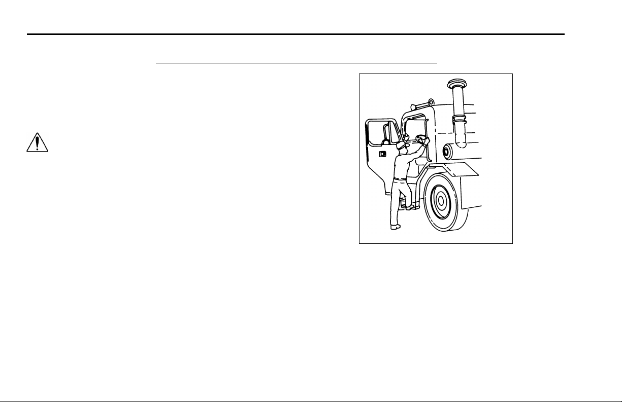
PART 2: CAB AND FRAME ACCESS
Be careful whenever you get into or out of your vehicle’s
cab. Always maintain at least three points of contact with
your hands on the grab handles and your feet on the steps.
WARNING! Jumping out of the cab or getting
into the cab without proper caution is dangerous. You could slip and fall, possibly suffering
a serious injury. Keep steps clean. Clean any
fuel, oil, or grease off of the steps before entering the cab. Use the steps and grab handles
provided, and always keep at least three points
of contact between your hands and feet and the
truck. Look where you are going.
The following pictures show the best way to enter and exit
a Model 320.
PART 2: CAB AND FRAME ACC ESS
02871
Three points of contact as you begin or finish
– 6 – Y53-6015 R(08/07)
Page 11
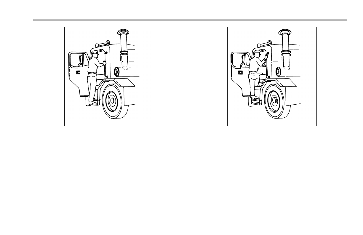
PART 2: CAB AND FRAME ACCESS Door Lock and Keys
02872
Three points of contact as you climb up or down
Three points of contact as you step in or out
02873
Door Lock and Keys
Doors can be locked from the inside by using the lock button. Close the door then push the button down to lo c k.
Doors automatically unlock when you open them from the
inside,andcanbelockedfromtheoutsidewithakeyonly.
R(08/07) Y53-6015 – 7 –
Page 12

Climbing Onto the Deck Plate PART 2: CAB AND FRAME ACCESS
WARNING! To lessen the chance and/or severity of personal injury in case of an accident, always lock the doors while driving. Along with
using the lap/shoulder belts properly, locking
the doors helps prevent occupants from being
thrown from the vehicle.
To lock or unlock the doors from outside the cab, insert the
key in the lock. Turn the key toward the rear to lock; forward
to unlock.
Climbing Onto the Deck Plate
WARNING!
• You can be hurt if you aren’t careful climbing onto and off the deck plate. You can slip
and fall, especially if the surfaces are wet or
icy, or if you step in oil, fuel, or grease. Keep
steps clean. Always maintain at least three
points of contact between your hands and
feet and the steps and deck plate.
• Do not climb onto and off the deck plate– use
steps and grab handle provided. If there is
no deck plate, or if proper steps and grab
handles aren’t provided, don’t climb onto the
area behind the cab. Peterbilt did not intend
for the area to be a step if handrails or proper
steps are not provided.
NOTE: Any alteration (adding bulkheads, headache racks, tool boxes, etc.) that affects the utilization of grab handles, deck plates, or frame
access steps installed by Peterbilt must comply
with FMCSR 399.
– 8 – Y53-6015 R(08/07)
Page 13
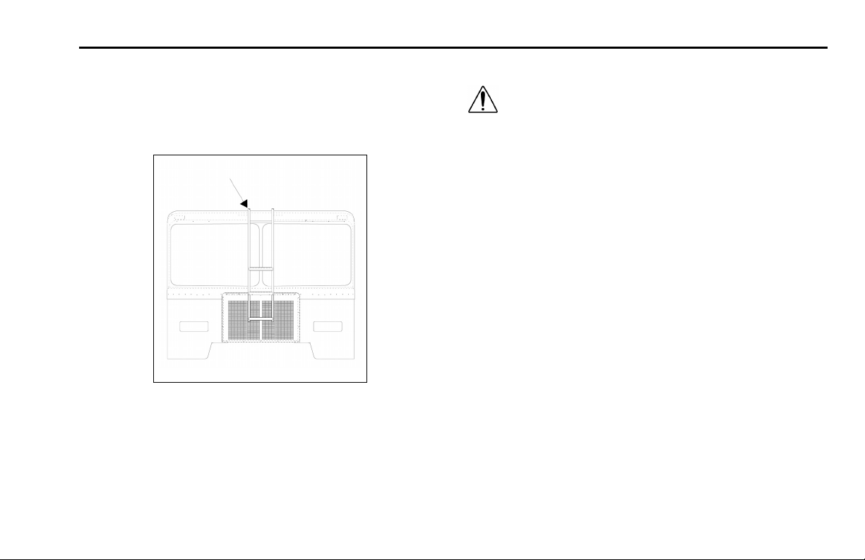
PART 2: CAB AND FRAME ACCESS Front Cab Guard/Ladder
Front Cab Guard/Ladder
The optional front cab guard/ladder is used on front-loading refuse vehicles to protect the cab from damage and to
stand on in order to remove debris from above the cab.
0001
WARNING!
• Do not climb on the cab roof. The cab roof
is not a slip-resistant surface and is not
equipped with handholds. A slip and fall
could cause serious injury.
• Do not step or stand on the top rung of the
ladder. This is not a step; it is meant to used
only as a handhold. You could slip or fall and
injureyourselfifyouuseitasastep.
R(08/07) Y53-6015 – 9 –
Page 14

Cab Tilting PART 3: GETTING TO YOUR ENGINE
PART 3: GETTING TO YOUR ENGINE
Cab Tilting
WARNING! You can be seriously injured by the
cab if you do not follow safety precautions.
Whenever you raise or lower the cab, or when
you work under the cab, please remember the
following safety rules:
• Be sure no one is under the front of the cab.
Whether you are raising or lowering the cab,
KEEP CLEAR.
• Never work under a raised cab unless it is
properly supported. This means use an overheadhoistofsufficient capacity to support
the cab safely. Never prop the cab up instead
of using a hoist. The prop could fail and let
the cab fall on you or anyone else working
under the cab.
• Always be sure the safety latch is engaged
when you or anyone else works under the
cab.
– 10 – Y53-6015 R(08/07)
• Perform work only when the cab is in the mechanically locked position or in the full tilt position.
• When your cab’s hydraulic system needs
service or repair:
• Have maintenance an d repair don e o nly by
someone qualified in hydraulic systems.
• Besurenoonetriestobleedthesystem
with the cab raised. This will defeat the
safety system. The cab can fall and crush
anyone under it.
• Do not tamper with any part of the cab tilt
cylinders, including removing the velocity
fuses. To do so will defeat their purpose.
The cab could fall and crush anyone under
it. If you have any need for repair involving
the velocity fuses, have a qualified truck
mechanic do the work.
NOTE: In case of oil loss in the system or a lockup
in the tilt cylinders, refer to the maintenance manual
for repair instructions.
Page 15

PART 3: GETTING TO YOUR ENGINE Raising the Cab
Raising the Cab
An independent hydraulic system raises and lowers the
cab. A positive, dual-locking device ensures safety and
eliminates danger of mishaps while driving.
WARNING! Do not get any part of your body under an unsecured cab. It could cause a serious
or fatal accident. The cab could fall and crush
you. Always ensure the locking bar is fully engaged before getting under the cab, or before
letting anyone else get under it (see following
instructions on using the locking bar).
WARNING!
• Raising the cab with heavy objects in the cab
can cause serious damage to the cab tilting
mechanism and cab. Before raising the cab,
remove heavy items su ch as tire chai n s and
tools. Remove or stow securely any loose
items. And shut the doors tightly.
• Straighten the front wheels before tilting the
cab or cab/tire damage could occur.
The following cab tilting instructions are labelled and installed on the base of the companion seat:
1. Park the vehicle on a level surface.
2. Apply the parking brake.
3. Make sure the shift lever is in Neutral. This will prevent
the shift lever from getting caught on the cab during
tilting operations.
4. Secure or remove all loose items in the cab. Close all
doors.
5. Check the clearance above and ahead of the cab. Ensure there will be enough room to clear roof antennae
when you tilt the cab. Check for obs tructions overhead
(branches, power lines, lights, etc.) and in front (walls,
work benches, other vehicles, etc.).
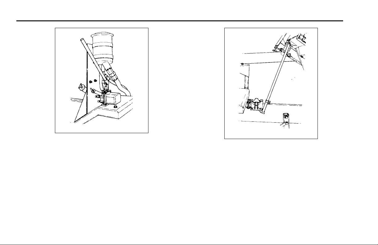
6. Place the control valve handle in the "Raise" position.
R(08/07) Y53-6015 – 11 –
Page 16
Raising the Cab PART 3: GETTING TO YOUR ENGINE
02874
Handle in "Raise" Position
02875
Locking Bar in Anchored Position
7. Attach pump handle to the pump and pump to raise the
cab (the latch hooks will release automatically when
pump is actuated). Pump until the locking bar can
be positioned on the anchor mounted below the right-
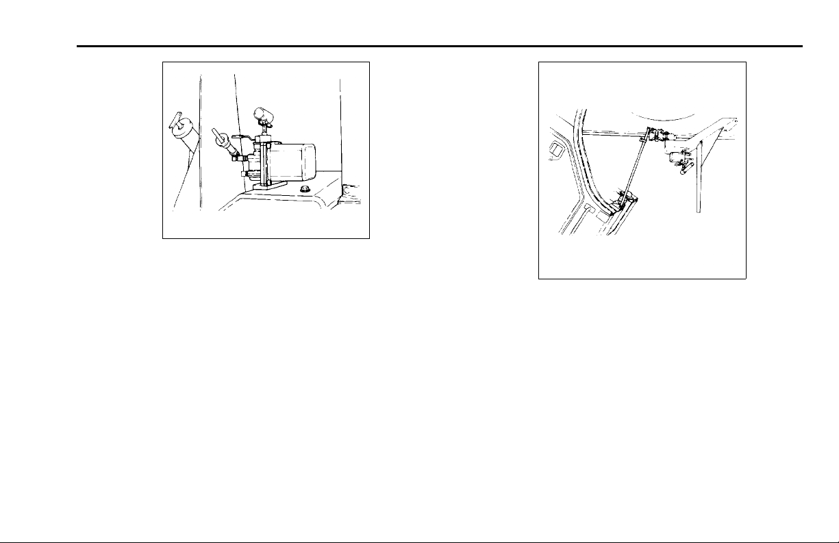
8. Place the control valve handle in the “Lower” position
and allow the cab to settle down slightly on the locking
bar.
hand cab suppo rt as shown in the next illustration.
– 12 – Y53-6015 R(08/07)
Page 17
PART 3: GETTING TO YOUR ENGINE Lowering the Cab
02876
Handle in "Lower" Position
02877
CabinFullTiltPosition
Lowering the Cab
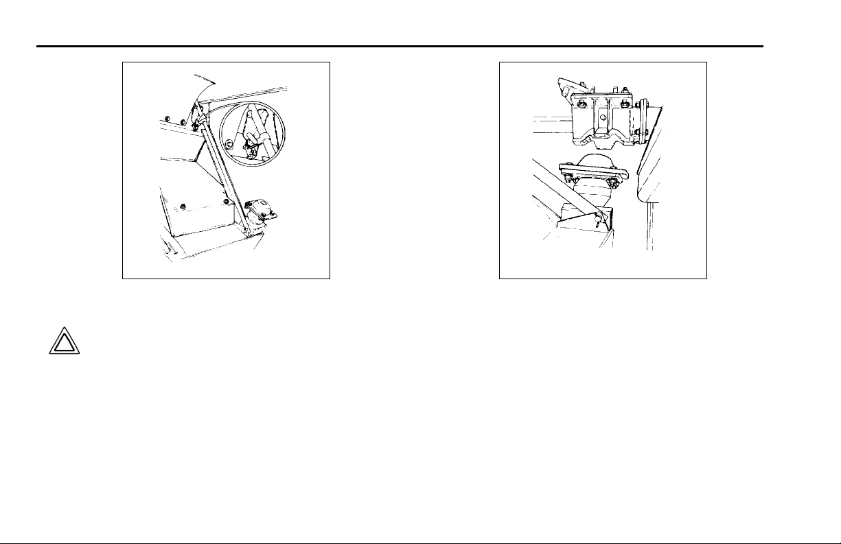
1. Place the control valve handle in the "Raise" position
and pump until the locking bar can be removed from
the anchor and fastened in its stored position.
R(08/07) Y53-6015 – 13 –
Page 18
Lowering the Cab PART 3: GETTING TO YOUR ENGINE
02878
Locking Bar In Stored Position
Upper and Lower Rear Cab Mount
02879
3. Allow at least 20 seconds after the cab touches down
CAUTION: Do not try to pump the cab down
or hold it down with hydraulic force. If you
do, cab damage will occur.
2. Place the control valve handle in the "Lower" position.
The cab should settle down on the rear mounts.
for the full spring force to develop in the latch hooks in
the rear mounts.
4. Remove the pump handle and store in the cab.
5. Visually inspect the cab latch hooks to ensure they are
closed.
6. Ensure that the control valve handle is in the “Lower”
position when operating the vehicle.
– 14 – Y53-6015 R(08/07)
Page 19

PART 4: CONTROLS AND DISPLAYS Your Instrument Panel
PART 4: CONTROLS AND DISP LAYS
This part explains the location of the various features on
your vehicle and describes their function. For inform at ion
on using these features in driving, see the paragraphs that
follow.
Your Instrument Panel
Please remember that each Peterbilt is custom-made. Your
instrument panel may not look exactly like the one in the
illustrations on the pages that follow.
We have tried to describe all the most common features
and controls available, so your vehicle may not have some
of the ones that appear in this section. You can pick out the
parts that apply to you and read them to be fully informed
on how your particular vehicle operates.
R(08/07) Y53-6015 – 15 –
Page 20
Your Instrument Panel PART 4: CONTROLS AND DISPLAYS
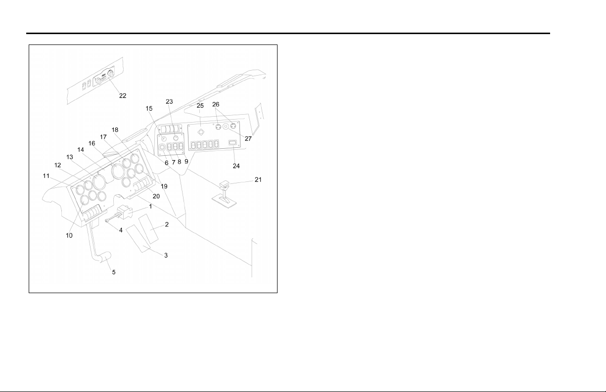
LEFT SIDE
0002
Typical Instruments & C ontrols: Left-Hand Drive Station
1. Turn Signal/Hazard Flasher
2. Accelerator Pedal
3. Brake Pedal
4. High Beam Switch
5. Clutch Pedal
6. Ignition Key Switch
7. Clearance Lamps Switch
8. SMC Select/Reset Switch
9. Headlight Switch
10. Voltmeter
11. Engine Oil Pressure
12. Engine Coolant Temperature
13. Tachometer
14. LED Warning Light Ba r
15. Panel Light Knob
16. Speedometer w/ Message
Center (SMC)
17. Primary Air Pressure
18. Fuel
19. Transmission Oil Temp.
20. Secondary Air Pressure
21. Gearshift or Shift Selector
22. Heater Control Panel
23. Cigar Lighter
24. Interaxle Differential Lock
25. Parking Brake Valve
26. Windshield Wiper Valves
27. Windshield Washer Switch
– 16 – Y53-6015 R(08/07)
Page 21
PART 4: CONTROLS AND DISPLAYS Warning Alarms
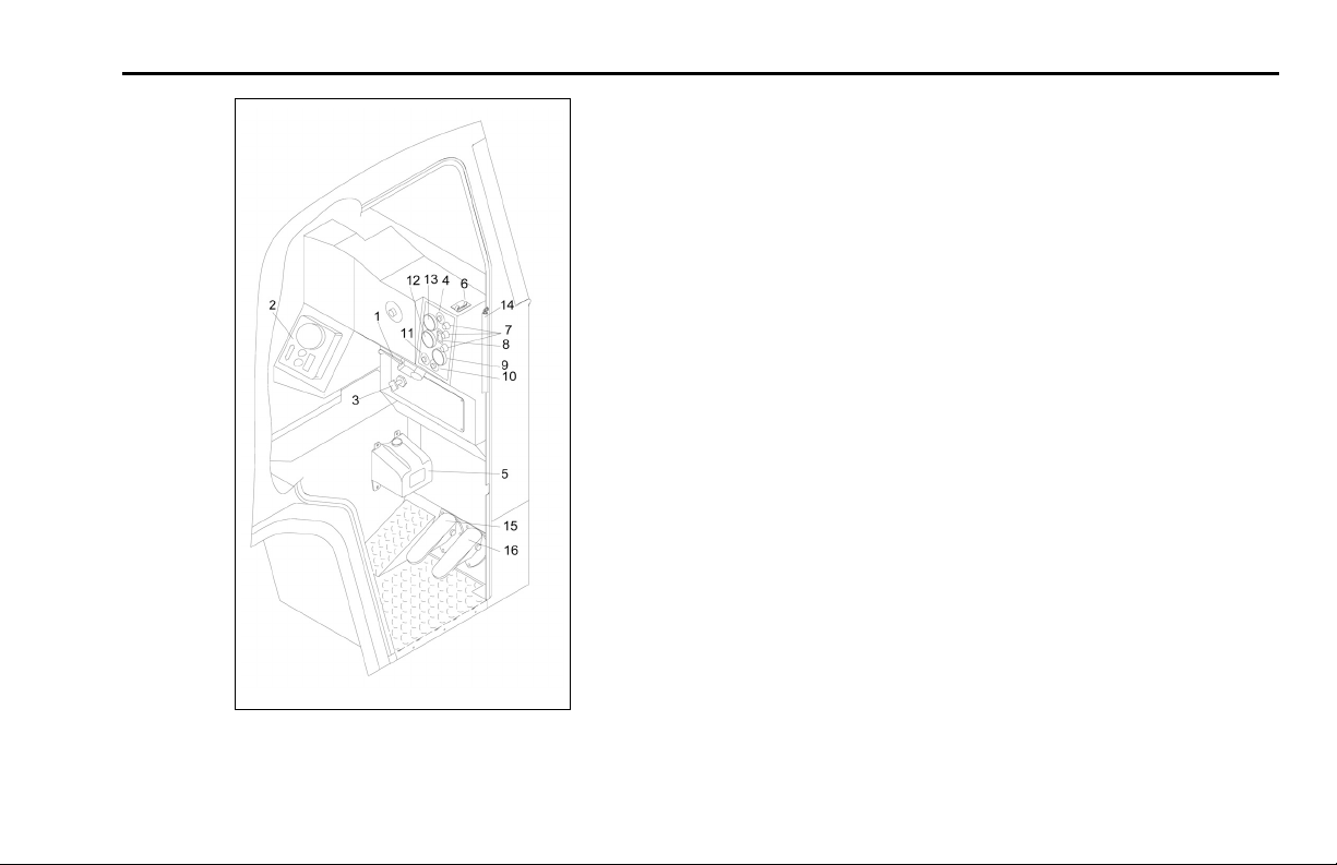
RIGHT SIDE
0003
Typical Instruments & Controls: Right-Hand Drive Station
1. Turn Signal/Hazard Flasher
2. Transmission Controls
3. Parking Brake Valve
4. Horn Button
5. Windshield Washer
Reservoir
6. Working Brake Switch
7. Warning Lights
8. Headlight Switch
9. Secondary Air Pressure
10. Starter Switch
11. Stop Switch
12. Prim a ry Air Pressure
13. Engine Oil Pressure
14. Safety Chain
15. Bra ke Pedal
16. Accelerator Pedal
Warning Alarms
A warning alarm occurs when some condition in the vehicle
requires attention. A warning alarm cannot be turned off or
manually reset. Once triggered, an alarm w ill continue to
exist until the unacceptable condition or fault in a function
is corrected.
R(08/07) Y53-6015 – 17 –
Page 22

Warning Alarms PART 4: CONTROLS AND DISPLAYS
NOTE:Inadditiontothewarningmessagesmentioned in this part - if any of the following conditions
occur after startup and self-test, the multiplex instrumentation system should be serviced
• The speedometer-message center (SMC)
pointer exhibits windshield wipe r-like motion
and the display reads NO DATA
• One or more gauge pointers exhibit wiper-like
motion.
• A gauge pointer stays at zero with its red light
flashing.
• A gauge pointer goes to and remains at a 2:00
position with its red light on steady.
A multiple x instrumentation system alarm can be sign a lled
by up to four indicators:
• A warning message will appear on the SMC display
(all alarms).
• The light-emitting diode (LED) warning light in the
function’s gauge will go on (all alarms except ABS
and multiplex instrumentation system faults).
• An audible alarm will sound.
• A light bar icon will light.
NOTE:
• Warning messages from system alarms with an
audible alarm can be temporarily overridden by
pressing the Reset switch. You can then press
the Select switch to scroll through other functions
- but the message will reappear in 60 seconds.
The audible alarm will always be on.
• Warning messages from system alarms without
an audible alarm can be dismissed by pressing
the Reset switch. To view dismissed active messages, turn the ignition off and back on.
An alarm’s warning message on the SMC will preemp t all
other SMC displays until the condition that is causing the
alarm is corrected. T his preemption includes other warning
messages from earlier alarms - and some of these alarms
may not have other indicators. Therefore, it is very important that you check the SMC to be aware of all alarm conditions that may exist in your vehicle’s systems - especially
during the start-up procedure. A summary of alarms and
indicators is at the end of this part. Follow this procedure
to check all SMC warning messages.
1. Obse rve the first message displayed after the SMC
comes on.
– 18 – Y53-6015 R(08/07)
Page 23

PART 4: CONTROLS AND DISPLAYS Warning Alarms
• If the odometer is displayed, continue with the
start-up procedure.
• If a warning m essage is displayed instead of the
odometer, it is being generated by the multiplex instrumentation syste m:
– Look in the alarm summary to identify the gauge.
– Go to the description of that gauge in"
PART 4:
CONTROLS AND DISPLAYS" and take the actions indicated to correct the condition.
2. Continue to check and act on all warning messages
until the odometer is displayed.
Multiplex Instrumentation System Alarm Summary
Display Activation
Condition
H2O TMP Coolant
temp. is high
IM CAL System Fault
IM CFG System Fault
Gauge LED
Engine Water
Temperature
None
None
Buzz Deactivation
yes
no
no
Display
H2OT OK
None
None
Display Activation
IM DIAG System Fault
IM LIN
IM SLFT System Fault
LOW
AIR1
LOW
AIR2
LO
WATER
NO DATA System Fault
ODO ERR System Fault
OIL TMP
OIL PRES
Condition
System Fault
Low air
pressure in
air tank #1
Low air
pressure in
air tank #2
Coolant level
is low
Engine oil
temperature
is high
Engine oil
pressure is
low
Gauge LED
None
None
None
Primary air
pressure
Secondary
air pressure
Engine Water
Level
None
None
Engine Oil
Temperature
Engine Oil
Pressure
Buzz Deactivation
no
no
no
yes
yes
yes
no
no
yes
yes
Display
None
None
None
AIR1 OK
AIR2 OK
WATER O K
None
None
OILT OK
OIL OK
R(08/07) Y53-6015 – 19 –
Page 24
Turn Signal and Indicator Lights PART 4: CONTROLS AND DISPLAYS
Display Activation
SMC
MEM
TRANTMP Main
Condition
System Fault
transmission
oil
temperature
is high
Gauge LED
None
Main
Transmission
Oil
Temperature
Buzz Deactivation
no
yes
Display
None
TRAN OK
Steering Column-Mounted Controls
Turn Signal and Indicator L igh ts
02882
Turn Signal
The turn signal body is mounted on the left side of the steering column, below the steering wheel.
• At a right-hand drive station, the turn signal body is
mounted on a stub shaft under the dash behind the
steering wheel.
– 20 – Y53-6015 R(08/07)
Page 25

PART 4: CONTROLS AND DISPLAYS High Beam Headlights
other vehicle could run into you if you do not set
NOTE: The ignition key must be turned to ON for
the signal/switch to operate.
To operate either signal, move the lever in the direction of
the turn.
Of course, in normal stopping in traffic, such as at a stop
light, you do not use your flashers.
your flashers. Always move the vehicle a safe
distance off the road when stalled or stopped
for repairs
Hazard Flasher
The four-way Hazard Flasher switch is on the turn signal
body, just below the turn signal lever.
• At a right-hand drive station, the switch is above the
lever.
The flasher will operate with the key switch in the on or off
position. Pull it out to activate the system. All turn signals
will flash at once. To turn it off, move the turn signal lever
up or down.
Use your hazard flasher whenever you are off the road or
on the side of the road, or in a potentially hazardous situation.
WARNING! Use your Hazard Flasher Warning
System any time you have to stop off the road or
on the side of the road, day or night. A hard to
see vehicle can result in an injury accident. An-
High Beam Headlights
All Model 320 vehicles c o me equipped with a co mbination turn signal and high beam / low beam switch that is
mounted to the steering column. To switch your headlights,
push and release the button on the end of the turn signal lever. The high beam indicator light is displayed in the
tachometer face
WARNING! Your disabled vehicle can be dangerous for you and others. The hot exhaust system could ignite dry grass, spilled fuel, or other
substances. Do not park or operate your vehicle w here the exhaust system could contact dry
grass, brush, spilled fuel, or any other material
that could cause a fire.
R(08/07) Y53-6015 – 21 –
Page 26
Trailer Brake Hand Valve PART 4: CONTROLS AND DISPLAYS
Trailer Brake Hand Valve
02885
02884
High Beam Headlight Switch Button
If your vehicle is a tractor, it will be equipped with a trailer
brake hand valve. This hand valve provides air pressure to
apply the trailer brakes only. It operates independently of
the foot treadle valve.
To operate the trailer brake hand valve: Pull down on
the lever on the right side of the steering column, below
the steering wheel.
Trailer B rak e Hand Valve
– 22 – Y53-6015 R(08/07)
Page 27
PART 4: CONTROLS AND DISPLAYS Electric Horn
WARNING! It is dangerous to use air-applied
trailer brakes for parking or holding a vehicle.
Air system pressure can bleed down and release the brakes. You could have a vehicle rollaway resulting in an accident. You or others
could be badly injured. Always apply the parking brakes for parking or holding your vehicle
on grade.
NOTE: The traile r brake is not to be use d as the
main means of braking. To use this brake frequently
instead of using the foot brake will wear out the
trailer brake sooner.
See "
Parking Brakes and Their Use" for more complete
information on when and how to use your trailer brake. Or
see the Index, under Brake.
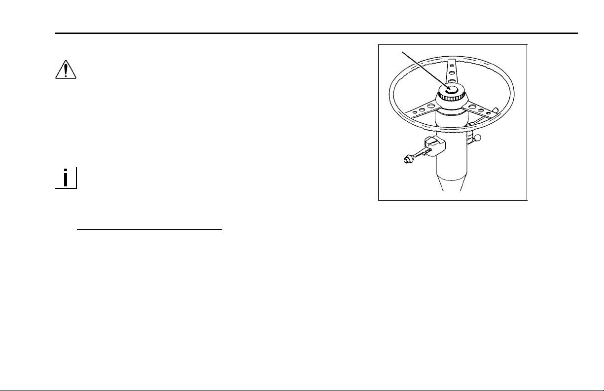
Electric Horn Button
Air Horn
Your Pe te rbilt has an a ir horn in addition to an electric horn.
02886
Control the air horn by pulling on the lanyard exten ding from
Electric Horn
the overhead header panel.
Your vehicle has an electric horn. To sound the horn, press
on the button in the center of the steering wheel. At a righthand stand-up drive station, the horn button is located on
the dash panel to the right of the steering wheel.
R(08/07) Y53-6015 – 23 –
Page 28

Ignition Switch PART 4: CONTROLS AND DISPLAYS
Dash-Mounted Features
Keys and Locks
The same key operates the ignition and opens the doors.
Frame-mounted tool box locks and locking fuel tank caps
each have individual keys.
Ignition Switch
Your ignition switch has four positions:
• OFF: In this (center) position, all accessories are off
(except those listed below), and you can remove the
key:
– Brake lights
– Panel lights
– Tail lights
– Cigarette lighter
– Clearance lamps
–Horn
– Headlights
– R adio station memory
– Emergency hazard flasher
– A uxiliary power
– Dome light
This is the key position that w ill stop the engine from the
left-hand drive stat ion.
• ACC (Accessory): In this position (to the left of center),
you can play the radio or use other accessories, but
your engine won’t start.
• ON: In this position (to the right of center), all circuits
except the cranking circuit are energiz ed. The warning light bar and the multiplex instrument system will
begin its start-up (self-test) p rocedure. In this switch
position, the key cannot be removed.
• START: When the key is turned and held in this position (full right of center), the starter motor will engage
and crank the engine. Also, it is not uncommon for
some or all of the multiplex instrument system gauges
to begin their start-up procedure again. This is due to
the drop in the system voltage during engine cranking.
NOTE: The multiplex instrument system start-up
(self-test) procedure is described in "
STARTING & OPERATING THE VEHICLE" of this
manual.
PART 7:
– 24 – Y53-6015 R(08/07)
Page 29
PART 4: CONTROLS AND DISPLAYS Manual Override for Engine Shutdown
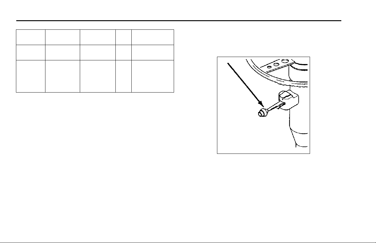
Starter Button
02887
With the ignition switch ON, pushing this button at the righthand drive station will perform the same function as turning
the key to the START position at the left-hand drive station.
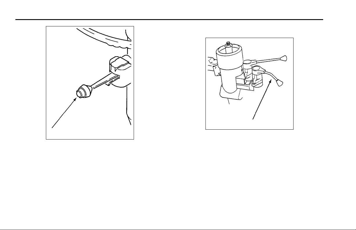
Stop Button
02888
Pushing this button at the right-hand drive station stops the
engine.
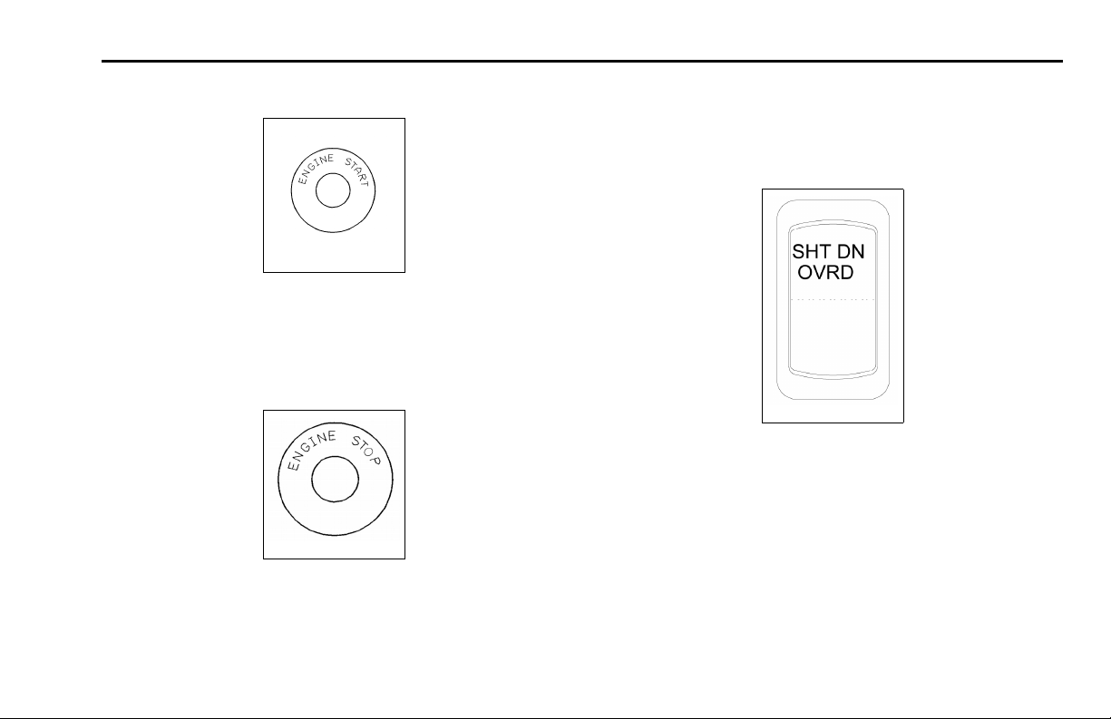
Manual Override for Engine Shutdown
03020
On vehicles with an engine shutdown, you will have to hold
the manual throw switch in the UP position until normal
engine pressures are reached. If you have one of these
systems, a label on the control panel will say so.
For detailed s tarting procedures, see the Index, under
Starting And Operating.
R(08/07) Y53-6015 – 25 –
Page 30
Panel Light Knob PART 4: CONTROLS AND DISPLAYS
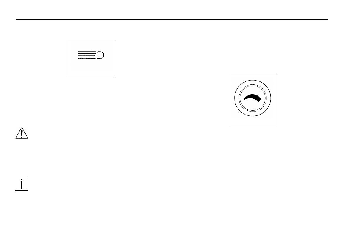
Headlights
02890
The headlights are controlled by the control panel
switch(es) showing the above symbol. When the headlights are ON, the dash lights, side, and tail lamps are also
on.
WARNING! Do not use daytime running lights
(DRL) during periods of darkness or reduced
visibility. Do not use DRL as a substitute for
headlights or other lights during operations that
require lighting of your vehicle. Doing so could
lead to an injury accident.
NOTE: On vehicles equipped with daytime running
lights (DRL), the high-beam headlamps go on automatically at reduced brightness if the engine is running and the headlamp s witch is turned off. The
daytime running lights are turned off automatically
while the parking brake is engaged. If the headlamp
switch is turned on, the DRL system is overridden
& headlamps operate normally.
Panel Light Knob
02891
The Panel Light Knob lets you vary the brightness of your
instrument panel lights.
To Operate Your Panel Light Knob:
1. Turn on either the headlights, c learance lights, or fog /
driving lights.
2. To brighten the instrument panel lights, turn the knob
clockwise.
3. To dim the instrument lights or to turn them off, turn the
knob counterclockwise.
– 26 – Y53-6015 R(08/07)
Page 31

PART 4: CONTROLS AND DISPLAYS Fog/Driving Lights Switch
ID and Clearance Lights Switch
02892
These are the amber lights on top of your cab, the lights on
the front and sides of the trailer and the red lights on the
rear of a truck or trailer. They are controlled by the control
panel switch shown above.
Fog/Driving Lights Switch
03021
If your vehicle has fog lights, turn them ON or OFF with the
control panel switch shown above.
NOTE: State requirements vary as to when high
beams and fog lights can and cannot be used together. Further, some states allow only four lights to
be used together; some allow more. Whether you
have dual or composite lights will affect how many
lights you can have on at one time. Always comply
with the state requirements where you are driving.
R(08/07) Y53-6015 – 27 –
Page 32

Windshield Wipers and Washers PART 4: CONTROLS AND DISPLAYS
Dome Light Switch
ENGINEER - 16-04 492
A two-position switch controls each dome light.
Windshield Wipers and Washers
02895
Wiper
To turn on the wiper(s), rotate the knob(s) clockwise. As
the knob is rotated, the speed of the wiper increases. To
turn off the wiper, rotate the knob counterclockwise.
Washer
To use the washer, push the button on the control panel
showing this symbol.
02896
WARNING! Do not drive with worn or dirty wiper
blades. They can reduce visibility, making driving hazardous. Clean blades regularly to remove road film and wax build-up. Use an alcohol based cleaning solution and a lint-free cloth,
and wipe along the blades.
– 28 – Y53-6015 R(08/07)
Page 33

PART 4: CONTROLS AND DISPLAYS Air Suspension DeflateSwitch(DumpValve)
CAUTION: Do not use antifreeze or engine
coolant in the windshield washer reservoir—
damage to seals and other components will
result.
Air Suspension Deflate Switch (Dump
Valve)
03035
If your vehicle is a tractor with a rear air suspension, it may
have an air suspension deflationswitchonthedashthat
allows the air in the suspension to be exhausted. The purpose of this feature is to allow you to lower your tractor to
get under a trailer.
You will notice a guard over the switch. This prevents you
from accidentally deflating the suspension.
WARNING! Operating the Air Suspension Deflate Switch (Dump Valve) while driving can lead
to an accident. Sudden deflation while your vehicle is moving can affect handling and control.
Use this switch only when your vehicle is not
moving.
CAUTION: Operating a vehicle with air suspension bags either overinflated or underinflated
may cause damage to driveline components. If
a vehicle must be operated under such conditions, do not exceed 5 mph.
R(08/07) Y53-6015 – 29 –
Page 34

Air Suspension Deflate Switch (Dump Valve) PART 4: CONTROLS AND DISPLAYS
Engine Fan Switch
03023
The engine fan switch allows you to control the engine fan
manually or autom atically. W ith the ignition key switch ON
and the fan switch in the ON position, the engine fan will
be on regardless of engine temperature. With the engine
fanswitchintheAUTOMATICposition,theenginefanwill
automatically turn on when the engine coolant reaches a
temperature of about 200° F (93° C).
WARNING! Do not work on the fan with the engine running. Anyone near the engine fan when
it turns on could be badly injured. If it is set
at ON, it will turn on any time the ignition key
switch is turned to the ON position. In AUTOMATIC, it could engage suddenly without warning. Before turning on the ignition or switching
from AUTOMATIC to O N, be sure no one is near
the fan.
CAUTION: The fan or equipment near it could be
damaged if the fan turns on suddenly when you
don’t expect it. Keep all tools and equipment
away from the fan.
NOTE: Do not operate the engine fan in the manual
(ON) position for extended periods of time. The fan
hub was designed for intermittent operation. Sustained operation will shorten the fan hub’s service
life as well as reduce fuel economy.
– 30 – Y53-6015 R(08/07)
Page 35

PART 4: CONTROLS AND DISPLAYS Mirror Heat S w it c h
Power Mirror Switch
03024
The power mirror control controls the adjustment o f the
right or left outside mirrors, depending on the option selected.
WARNING! Convex mirrors can distort images
and make objects appe ar smaller and farther
away than they really are. You could have an
accident if you are too close to another vehicle or other object. Keep plenty of space between your vehicle and others when you turn or
change lanes. Remember that other objects are
closer than they may appear.
NOTE: The Power Mirror Switch does not control
the adjustment of the convex mirrors
Mirror Heat Switch
03022
Mirror heat is controlled by the control panel switch shown
above. If the vehicle is equipped with this switch, mirror
heatcanbeswitchedontohelpremovefrostandicefrom
the mirror glass.
R(08/07) Y53-6015 – 31 –
Page 36

Engine Brake PART 4: CONTROLS AND DISPLAYS
Cruise Control Switch
The master switch turns the cruise control ON or OFF. The
second switch allows you to SET the desired speed or RESUME the desired speed after the cruise control function
has been interrupted.
03025_26
WARNING! Do not operate the cruise control
when operating on road surfaces with poor
traction (wet, icy, or snow covered roads) or in
heavy traffic. Accelerations caused by the normal operation of the cruise control could cause
you to lose control of the vehicle resulting in
an injury accident.
NOTE: Cruise control functions and features may
vary depending upon which engine you have. For
specific explanation of your cruise control, see th e
cruise control or engine manual included with your
vehicle.
Engine Brake
03028
– 32 – Y53-6015 R(08/07)
Page 37

PART 4: CONTROLS AND DISPLAYS Interaxle Differential Lock Switch
When an engine brake is energized, the power-producing
diesel engine is converted into a powe r-absorbing air compressor to retard the vehicle.
• The brake is energized whenever the driver’s foot is
completely removed from the accelerator pedal.
• The brake is deenergized during driving by pressure
on the accelerator pedal, and during shifting by depressing the clutch pedal.
The ON/OFF toggle switch turns the system ON or OFF.
• In Caterpillar and C ummins L10-powered vehicles
equipped with a Jacobs Engine Brake, a second,
two-mode switch is incorporated in the instrument
panel. With this system, you can select either LOW
or HIGH retarding.
For more information on when and how to use the engine
brake in your vehicle, see the owner ’s manual for the engine brake that is included with your vehicle.
WARNING! Using the engine brake when operating on surfaces with poor traction (such as
wet or icy, slippery roads or gravel) could cause
loss of control.
Interaxle Differential Lock S witch
03029
The interaxle differential allows differential action between
the forward rear and the rear driving axles. The interaxle
differential lock switch allows the operator to LOCK or UNLOCK the differential. There is a guard over this switch to
prevent you from accidentally activating the lock.
R(08/07) Y53-6015 – 33 –
Page 38

Fifth Wheel Lock (Slider Adjustment) Switch PART 4: CONTROLS AND DISPLAYS
WARNING! Placing the differential lock in the
“LOCK” position while your wheels are spinning could cause loss of control or axle damage. You could be hurt. Switch to “LOCK” only
when your wheels are not spinning.
See "
Interaxle Differential" for more information on using
your interaxle differential.
Two-Speed Rear Axle (Range) Switch
03030
If your vehicle is equipped with a two-speed rear axle, you
can select the axle range by the dash-mounted switch
shown above. The low range provides maximum torque
for operating off-highway. The high range is a faster ratio
for highway speeds. There is a guard over this switch to
prevent you from accidentally changing speeds.
For information on how to operate your two-speed rear axle
properly and safely, see "
ING TH E VEHICLE" or check the Index, under Two-Speed
Rear Axle (Range) Switch 29.
PART 7: STARTING & OPERAT-
Fifth Wheel Lock (Slider Adjustment)
Switch
03031
Vehicles having an air-slide fifth wheel have a fifth wheel
slider lock controlled by a switch on the instrument panel.
– 34 – Y53-6015 R(08/07)
Page 39

PART 4: CONTROLS AND DISPLAYS Parking Brake Valve and Trailer Air Supply Valve
By placing the switch in the unlock position, you can slide
the fifth wheel to various positions to adjust weight distribution.
There is a guard over this switch to protect you against
accidentally activating or releasing the lock.
WARNING! Do not move the fifth wheel w hile
the tractor-trailer is in motion. Movement of the
fifth wheel while a tractor-trailer is moving can
cause a serious accident. Your load could shift
suddenly, causing you to lose control of the vehicle. Never operate the vehicle with the switch
in the unlock position. Always inspect the fifth
wheel after you lock the switch to be sure the
fifth wheel is engaged.
Parking Brake Valve and Trailer Air
Supply Valve
02908
Single Valve
Your parking brake va lve is a yellow diamond-shaped knob
located on the right-hand control panel. It controls the parking brakes for either straight truck or tractor-trailer combinations.
• At a right-hand drive station, a second single valve is
located on the dash to the left of the steering wheel.
R(08/07) Y53-6015 – 35 –
Page 40

Heating And Air Conditioning Controls PART 4: CONTROLS AND DISPLAYS
If your vehicle is a tractor, a red, octagonal-shaped knob
will be next to the parking brake valve on the right-hand
control panel. This is the trailer air supply valve for selecting operation with or without a trailer
02909
Two-Valve System
• To apply all parking brakes, pull the yellow, or parking
brake, knob out. The truck or tractor parking brakes
will set. If equipped, the Trailer Air Supply Valve (red
octagonal knob) will automatically trip (“pop out”) and
set the trailer parking brakes.
• To release truck parking brakes, push in the yellow
knob. If a tractor with trailer, push in both the yellow
and the red knobs.
For full information on parking bra kes, see the Index, und e r
Brake.
WARNING! Stopping with the parking brake
controls can cause a sudden wheel lock-up,
loss of control, or can cause you to be overtaken by following vehicles. You could be
severely injured. Never pull out the parking
brake valve while the vehicle is moving.
Heating And Air Conditioning Controls
WARNING! Exhaust fumes from the engine contain carbon monoxide, a colorless and odorless
gas. Do not breathe the engine exhaust gas.
A poorly maintained, damaged or corroded exhaust system can allow carbon monoxide to enter the cab. Entry of carbon monoxide into the
cab is also possible from other vehicles nearby.
Failure to properly maintain your vehicle could
cause carbon monoxide to enter the cab and
cause serious illness.
– 36 – Y53-6015 R(08/07)
Page 41

PART 4: CONTROLS AND DISPLAYS Heating And Air Conditioning Controls
CAUTION: Never idle your vehicle for prolonged
periods of time if you sense that exhaust fumes
are entering the cab. Investigate the cause of
the fumes and correct it as soon as possible.
If the vehicle must be driven under these conditions, drive only with the windows slightly
open. Failure to repair the source of the exhaust fumes may lead to personal harm.
NOTE: Keep the engine exhaust system and the
vehicle’s ventilation system properly maintained. It
is recommended that the vehicle’s exhaust system
and cab be inspected
• by a competen t technician every 15,000 miles
• when a change is noticed in the sound of the
exhaust system
• if the exhaust system, underbody, or cab is damaged
NOTE: To allow for proper operation of the vehicle ventilation system, keep the inlet grille at the
base of the windshield clear of snow, ice, leaves
and other obstructions at all times.
NOTE: Do not stay in the vehicle with the engine
running or idling for more than 10 minutes with
the vehicle’s Heater / AC v entilation system in
RECIRC or at LOW FAN SPEED. Even with the
ventilation system On, running the engine while
parked or stopped for prolonged periods of time is
not recommended.
NOTE: If you are required to idle your vehicle for
long periods of time, install an auxiliary heater or
automatic idle control. These auxiliary devices can
reduce fuel consumption and save you money.
NOTE: When idling for short periods of time
• Set the heating or cooling system to Heat or A/C
• Set the fan to Medium or High speed
• Set the controls to FRESH AIR
NOTE: If other vehicles are parked next to you
idling, move your vehicle or do not stay in your
vehicle for prolonged periods of time.
R(08/07) Y53-6015 – 37 –
Page 42

Heating And Air Conditioning Controls PART 4: CONTROLS AND DISPLAYS
Heating System
The heating system is a variable-coolant - flow type of system.
• Hot engine coolant is circulated by the engine water
pump through a heater core within the heater unit.
• Two blowers force air through the core and into the
cab.
The amount of heat is controlled by:
02981A
• the position of the modulating water valve that regulates hot engine coolant flow
• the choice of fresh air or recirculated cab interior air as
feed air to the blowers
• the speed of the blowers
The system’s controls are mounted in the header in front
of the driver. They include the following (see illustration
below):
• A rotary knob to operate the modulating water valve
(for air temperature control), located in the heater con-
Next to the rotary k nobs, two switches are available for the
following functions:
• A switch to select either fresh air or recirculated cab
air as blower feed air.
• A switch to select cab interior or defrost vents for
heated air output.
To heat the cab, select the "Cab” mode and the desired
air source, then adjust the air temperature lever and blower
speed until comfortable.
trol head.
• A rotary switch to select blower speed, located in the
heater control head.
– 38 – Y53-6015 R(08/07)
Page 43

PART 4: CONTROLS AND DISPLAYS Heating And Air Conditioning Controls
WARNING! Do not drive with visibility reduced
by fog, condensation, or frost on the windshield. Your view may be obscured, which
could result in an injury accident. For clear visibility and safe driving it is extremely important
for you to follow the instructions pertaining to
the function and use of the ventilation/heating
and defogging/ defrosting system. If in doubt,
consult your dealer. Maximum heating output
and fast defrosting can be obtained only after
the engine has reached operating temperature.
CAUTION: During extreme cold weather, do not
blow hot defroster air onto cold windshields.
This could crack the glass. Turn the air flow
control lever to Defrost and adjust the fan speed
accordingly while the engine warms. If the engine is already warm, move the temperature selector to Cool, then gradually increase the temperature when you see that the windshield is
starting to warm up.
CAUTION:
• A cold compressor can cause refrigerant to
liquefy and warp the valve plates or cause a
hydraulic lock. Warm the engine before starting the air conditioner.
• To avoid damage to the compressor & blower
motors, turn off all controls when a system is
not in use.
NOTE: Air registers are located on both sides of the
cab. They may be positioned to clear (defrost) the
side windows. Closing these nonwindshield registers may help to defrost the windshield quicker.
• To defrost the windshield, select the "Defrost” mode
and the desired air source, then set the air temperature
lever to “Hot” and the blower speed to “High.” [Note: If
yourvehicleisequippedwitharoofmountedairconditioner, turn the air conditioner switch on.] When the
windshield is clear, adjust the temperature and blower
speed until comfortable.
R(08/07) Y53-6015 – 39 –
Page 44

Heating And Air Conditioning Controls PART 4: CONTROLS AND DISPLAYS
Air Conditioning System
Your vehicle may be equipped with either of two air conditioning systems. Cab interior air is continuously recirculated and cooled by these systems. In both systems, the
compressor, receiver-dryer, and condenser are located in
the engine compartment. (Note: In some applications, the
condenser may be mounted on the cab roof.)
Dash-mounted System
02981A
In one system, the evaporator and blower are located inside the heater unit, under the passenger dashboard. Controls for this system are located in a modified heater control
head.
To cool the cab, turn on the air conditioning system, then
adjust the air temperature and blower speed until comfortable. The amount of cooling is controlled by
• the temperature of the evaporator core
• the speed of the blower that forces air through the core
andintothecab
• the amount of heat added to the recirculated cab air
by the air temperature control
Ceiling-mounted System
In another system, the evaporator and blower are located
in a ceiling-moun te d unit. This system’s control panel is
– 40 – Y53-6015 R(08/07)
Page 45

PART 4: CONTROLS AND DISPLAYS Heating And Air Conditioning Controls
mounted in the cover piece of the unit located in the cab
ceiling. It contains a rotary switch to select blower speed
(see next illustration).
JPR033
To cool the cab, turn on the air conditioning system and
adjust the blower speed until comfortable. The amount of
cooling is controlled by
• the temperature of the evaporator core
• the speed of the blower that forces air through the core
and into the cab
NOTE: When the air conditioner isn’t in regular use,
operate it for at least 15 minutes once a month. This
will lubricate the seals in the system
For More Efficient Heating and Cooling...
• For immediate heating of a cold cab, operate the heating system with the “Fresh/Recirc” switch in the “Recirc” position. Switch to the “Fresh” position when the
cab has reached a comfortable temperature.
• For immediate cooling of a hot cab, initially open a
cab window. For maximum summertime cooling, both
heater control valves on the engine should be shut (if
so equipped).
• For both heating & cooling, use lower blower speeds
and intermediate temperature selector positions to
modulate cab temperature.
R(08/07) Y53-6015 – 41 –
Page 46

Gauges And Displays PART 4: CONTROLS AND DISPLAYS
Cigarette Lighter
02912
To operate your lighter, push the knob in. After a few moments the lighter will automatically pop out, ready to use.
After use, insert the knob, but don’t push it in. The lighter
circuit is p rotected by a 20-ampere fuse to prevent damage
should the lighter get stuck in the IN position. If this fuse
needs replacement, check to ensure that the lighter is not
stuck before replacing the fuse.
WARNING! Do not exceed the voltage/amperage capacity of the cigarette lighter. It could result in a fire. Follow all warnings and instructions in the operator’s manual for the appliance
you are using.
The lighter receptacle may be used to power auxiliary
equipment that does not draw more than 20 amperes
maximum.
Gauges And Displays
On the pages that follow you will find descriptions of some
of the gauges on your instrument panel. For more information about using them in driving, see "
& OPERATING THE VEHICLE". Also check the Index under the name of the gauge or function you want to know
more about.
WARNING! Do not ignore a warning light or
buzzer. These signals tell you something is
wrong with your vehicle. It could be a failure in
an important system, such as the brakes, which
couldleadtoanaccident. Havetheappropriate
system checked immediately.
PART 7: STARTING
– 42 – Y53-6015 R(08/07)
Page 47

PART 4: CONTROLS AND DISPLAYS Speedometer-Message Center (SMC)
Speedometer-Message Center (SMC)
NOTE: All of the warning lights and alarms for functions monitored by the multiplex instrumentation
system are contained within the individual gauges
of the system. The alarms for other controls or
systems that you may have will be displayed separately on the instrument panel. They are described
further in "
THE VEHICLE" of this manual.
PART 7: STARTING & OPERATING
112 43
The speedometer-message center (SMC) is a combination
of a speedometer and a message center. The speedometer indicates your vehicle’s speed in both miles and kilometers per hour. The message center contains a 7- character, segmented LCD scree n that can display the following
items:
•Odometer
• Trip1odometer
R(08/07) Y53-6015 – 43 –
Page 48

Speedometer-Message Center (SMC) PART 4: CONTROLS AND DISPLAYS
• Trip2odometer
• Hourmeter
•Clock
• Clock alarm
• Warning and Diagnostic messages (see "
strumentation Syst e m Alarm Summary")
A Select/Reset switch on the right side of the dash controls
the display.
The odometer is normally displayed on the screen. To
choose another function, press and release the Select
switch until it appears.
• The odometer reads m iles & tenths; e.g., 123456.7
• The Trip 1 odometer reads miles & tenths; e.g.,
1234.5T1
• The Trip 2 odometer reads miles & tenths; e.g.,
1234.5T2
• The hourmeter reads in hours; e.g., 12345HR
• The clock reads in hours & minutes, with A.M. or P.M.
indicated at the end; e.g., _ _ 12:34A (or P).
• If the clock alarm is set and activated, the display will
appear as * _ 12:34A (or P).
• The clock alarm reads in hours & minutes, with A.M.
or P.M. indicated as shown; e.g., AL12:34A (or P).
Multiplex In-
To set or reset a function, follow the procedures below.
NOTE: Neither the odometer nor the hourmeter can
be reset.
1.TurntheignitionswitchtoON.
2. Choose the desired function.
3. Set or reset the f unction:
• Trip Odometers: Press and hold the Reset switch
until the mileage is reset to zero; this will take about
3 seconds.
•Clock
Press & release the Reset switch; the hours digit
will flash.
A. Press & hold the Select switch; the hours digits
will increase until the switch is released. Scroll
through 12 hours to change between A.M. and
P. M .
B. Press & release the Reset switch; the hours dig-
its will stop flashing, and the minutes digits will
begin to flash.
C. Press & hold the Select switch; the minutes digits
will increase until the switch is released.
D. Press & release the Reset switch; the minutes
digits will stop flashing. The clock is now set.
– 44 – Y53-6015 R(08/07)
Page 49

PART 4: CONTROLS AND DISPLAYS Speedometer-Message Center (SMC)
•ClockAlarm
A. Press & release the Reset switch; the hours digit
will flash.
B. Press & hold the Select switch; the hours digits
will increase until the switch is relea se d. Scroll
through 12 hours to change between A.M. and
P. M .
C. Press & re lea se the Reset switch; the hours dig-
its will stop flashing, and the minutes digits will
begin to flash.
D. Press & hold the Select switch; the minutes digits
will increase until the switch is released.
E. Press & release the Reset switch; the m inutes
digits will stop flashin g. The alarm is now s et and
activated (the “*” symbol will show in the clock
display to indicate this).
– To t urn the alarm OFF or ON, p res s & hold the
Select sw itch for 3 seconds while v iewing any
display.
– To deactivate the buzzer when the alarm
sounds, press & release the Select switch.
(Note: The alarm will automatically deactivate
after 60 seconds.)
NOTE: When the ignition is OFF, the SMC will be
in a “sleep” (blank) mode. To “awaken” it, press
the “Select” switch. The SMC will function normally
while awake; it will return to a “sleep” mode 20 seconds after a switch is last pressed.
Further use and operation of the S MC is covered in "
7: STARTING & OPERATING THE VEHICLE" of this manual.
PART
R(08/07) Y53-6015 – 45 –
Page 50

Air Application Gauge PART 4: CONTROLS AND DISPLAYS
Tachometer
11244B
Your tachometer measures the engine speed in revolutions- per-minute (RPM). Watching your tachometer is important to driving efficiently. It will let you match driving
speed and gear selection to the operating range of your
engine. If your engine speed gets too high, you can select
a higher gear to lower the RPM. If your engine speed drops
too low, you can select a lower gear to raise the RPM.
Air Application Gauge
114 58
This gauge will show you how much air pressure is being
applied from your foot brake valve or trailer brake hand
valve.
– 46 – Y53-6015 R(08/07)
Page 51

PART 4: CONTROLS AND DISPLAYS Primary And Secondary Air Pressure Gauges (Air Reservoir)
Primary And Secondary Air Pressure
Gauges (Air Reservoir)
These air pressure gauges indicate the amount of air pressure in the brake system in pounds per square inch (psi).
The primary gauge shows the front reservoir air pressure:
114 65
The secondary gauge indicates pressure in the rear reservoir:
114 64
R(08/07) Y53-6015 – 47 –
Page 52

Engine Oil Pressure Gauge PART 4: CONTROLS AND DISPLAYS
WARNING! The air pressure warning light and
the audible alarm indicate a dangerous situation. There is not enough air pressure in the
reservoirs for repeated braking and the brake
system has failed. If air pressure falls below 60
psi (414 kPa) the spring brakes could suddenly
apply, causing a w heel lockup, loss of control,
or your vehicle to be overtaken by following vehicles. You could be in an accident and severely
injured. Ifthesealarmscomeonwhileyouare
driving, bring your vehicle to a safe stop right
away. If the light and alarm do not turn off at
start-up, do not try to drive the vehicle until the
problem is found and fixed.
Engine Oil Pressure Gauge
11241A
It is important to maintain oil pressure within acceptable
limits. Your engine manual will give normal operating pressures for your engine.
CAUTION: Continuing to operate your vehicle
with insufficient oil pressure will cause serious
engine damage.
– 48 – Y53-6015 R(08/07)
Page 53

PART 4: CONTROLS AND DISPLAYS Water Temperature Gauge
• If your oil pressure fails to rise within 10 seconds after
your engine starts, stop the engine and determine the
cause.
• If your oil pressure suddenly drops while you are driving,bringthevehicletoastopassoonaspossibleina
safe locat i on off the road an d turn off the engine. Wait
a few minutes to allow oil to drain into the oil pan, and
then check the oil level. Add oil if necessary. If the
problem persists, contact an authorized service center.
Check the engine manufacturer’s manual for the correct oil
pressure ranges for your engine.
Water Temperature Gauge
11242A
The water temperature gauge shows the temperature of
the engine coolant. Under normal operating conditions the
water temperature gauge should register between 165° 205° F (74° and 90° C), depending on the engine. Under certain conditions, somewhat higher temperatures may
be acceptable. But the maximum allowable temperature is
225° F (107° C) with the cooling system pressurized, ex-
R(08/07) Y53-6015 – 49 –
Page 54

Water Temperature Gauge PART 4: CONTROLS AND DISPLAYS
cept for certain special engines. Check your engine manual to be sure.
Engine Overheating
WARNING! Do not remove the radiator fill cap
while the engine is hot. Scalding steam and
fluid under pressure may escape and cause
serious personal injuries. You could be badly
burned.
• Wait until the coolant temperature is below
122°F (50°C).
• Protect face, hands, and arms by covering
the cap with a large, thick rag to protect
against escaping fluid and steam.
• Carefully and slowly turn the cap one-quarter of a turn or until it reaches the first stop—
allowing excess pressure to escape—push
down and turn for final removal.
Wait until the coolant temperature is below 122° F (50° C).
Protect your face, hands, and arms by covering the cap
with a large, thick rag to protect you against escaping fluid
and steam. Before you completely remove the cap, carefully and slowly turn the cap part way to allow excess pressure to escape. Then push down and turn for fina l r emoval.
The cooling system may overheat if the coolant level is
below normal or if there is a sudden loss of coolant (such
as a worn hose splitting). It may also temporarily overheat
during severe operating conditions such as climbing a long
hill on a hot day or stopping after high-speed driving.
If the “Engine Coolant Temperature” warning light comes
on, or you have any other reason to suspect the engine
may be overheating:
• Stop the vehicle, but DON’T TURN OFF THE ENGINE
unless a low water warning device indicates a loss of
coolant.
• With the transmission in neutral, check to be certain
the oil pressure gauge reads normal. Increase the
engine speed to about 1100 - 1200 R PM, maximum.
Return the idle speed to normal after 2 or 3 minutes.
If the warning light doesn’t go off or the temperature
gauge doesn’t begin to drop, then turn the engine off.
• If the overheating came from severe operating conditions, the temperature should have cooled by this
– 50 – Y53-6015 R(08/07)
Page 55

PART 4: CONTROLS AND DISPLAYS Fuel Gauge
time. If it has not, stop the engine and let it cool before
checking to see if the coolant is low.
Fuel Gauge
114 35
WARNING! Do not remove a fuel tank cap near
an open flame. Hot fuel vapors are combustible
and can cause an explosion or fire resulting in
injury or death.
The fuel gauge shows the approximate amount of fuel in
the fuel tanks. You will want to keep your fuel tanks at least
half full to reduce condensation of moisture in the tanks.
This moisture can damage your engine.
WARNING! Carrying additional fuel containers
in your vehicle is dangerous. Full or empty,
they may leak, explode, and cause or feed a fire.
Don’t carry extra fuel containers - even empty
ones.
R(08/07) Y53-6015 – 51 –
Page 56

Front Drive Axle or Rear Drive Axle Temperature Gauge PART 4: CONTROLS AND DISPLAYS
Transmission Temperatu re Gauge
114 27
Your Transmission Temperature Gauge indicates the temperature of the oil in your transmission. Watch this gauge to
know when your transmission is overheating. If it is, have
it checked by an authorized service representative. Maximum transmission temperature may vary, depending upon
the transmission and type of lubricant. It is typically 250° F
(121° C); check your transmission’s owner’s manual.
Front Drive Axle or Rear Drive Axle
Temperature Gauge
114 25
– 52 – Y53-6015 R(08/07)
Page 57

PART 4: CONTROLS AND DISPLAYS Manifold Pressure Gauge
CAUTION: Driving with very hot temperatures in
your rear drive axles can cause serious damage
to axle bearings and seals. Check axle lubrication if a driver temperature alarm sounds.
These gauges indicate the temperature of the lubricant in
your vehicle’s axle(s). These temperatures will vary with
thekindofloadyouarecarryingandthedrivingconditions
you encounter. Maximum axle temperature may vary, depending upon the axle and type of lubricant. Very high temperatures signal a need to have your axle(s)’ lubrication
checked.
Manifold Pressure Gauge
11453-1
Your manifold pressure gauge indicates the power your engine is putting out by showing the amount of turbo boost.
If the pressure indicated by your manifold pressure gauge
goes down, there may be something wrong with your engine. Have it checked by a qualified service person.
R(08/07) Y53-6015 – 53 –
Page 58

Air Filter Restriction Indicator Gauge PART 4: CONTROLS AND DISPLAYS
Voltmeter
114 97
Your voltmeter displays the battery voltage. Normally, it
should show 12V to 14V (volts).
NOTE: Even with a healthy charge/start system,
the voltmeter may fall well below 12V during engine cranking. If voltage drops below 12V and stays
there, have the electrical system checked.
Air Filter Restriction Indicator Gauge
114 95
This gauge indicates the condition of the engine air cleaner
and is measured by inches of water (H2O). A clean filter
should register 7” H2O (may vary with system design); a
filter whose life is over will register approximately 20” H2O
(for Cummins engines) or 25” H2O (for Caterpillar engines).
– 54 – Y53-6015 R(08/07)
Page 59

PART 4: CONTROLS AND DISPLAYS Shift Pattern Display
CAUTION: Continued operation with the Air
Filter Restriction Gauge reading 25” H2O may
cause damage to the engine. Inspect the filter
and replace if necessary. Holes in the paper
element render an air cleaner useless and may
cause the Air Filter Restriction Gauge to give
a false reading, even if the element is clogged.
Replace the element if it is damaged.
Warning Light Bar
Warning Light Bar
WARNING! Ignoring a warning light could lead
to an accident. These signals tell you something is wrong with your vehicle. It could be
a failure in an important system, such as the
brakes. Never ignore a warning signal. Have
the appropriate system checked right away.
The warning lights and buzzer may indicate something is
wrong with one of the vital systems on your vehicle. Check
the lights frequently, and respond properly as soon as you
see one go on (see "
could save you from a serious accident.
R(08/07) Y53-6015 – 55 –
ABS Warning Lamp s"). These lights
When you turn on your ignition, the warning light bar icons
will turn on for 3 - 5 seconds, as a test to let you know they
are working.
Shift Pattern Display
The correct shift pattern for your vehicle appears on your
control panel or windshield o r on a medallion in the shift
knob. It is important that you know more about your transmission than just the shift pattern. Please read the manufacturer’s manual that is included with your vehicle.
07802
Page 60

Mirrors PART 4: CONTROLS AND DISPLAYS
Mirrors
WARNING! Optional convex outside rear-view
mirrors make objects appear smaller and farther away than they really are. You could have
an accident if you were too close to another vehicle or other object. Keep plenty of space between your vehicle and others when you turn or
change lanes. Remember that other objects are
closer than they seem.
Your vehicle is equipped with outside mirrors to enable you
to see to the sides and behind your vehicle. Be sure they
are adjusted properly before you drive off. You will have
the best field of view to the side if you adjust each mirror
so you can just see the side of your vehicle in the inboard
part of the mirror.
– 56 – Y53-6015 R(08/07)
Page 61

PART 5: SEAT AND RESTRAINT SYSTEMS Seat Belts And Their Proper Use
PART 5: SEAT AND RESTRAINT SYSTEMS
Seat
For information on the features and adjustment of the seat,
see the seat manufacturer’s literature included with the vehicle.
WARNING!
• Do not drive or ride wit h your seat back in
the reclined position. You could be injured
by sliding under the seat belts in a collision.
• Do not adjust the driver’s seat while the vehicle is moving. The seat could move suddenly
and unexpectedly and can cause you to lose
control of the vehicle. Make all adjustments
to the seat while the vehicle is stopped. After adjusting the seat and before driving off,
ensure that the seat is firmly latched in position.
R(08/07) Y53-6015 – 57 –
Seat Belts And Their Proper Use
Seat (or safety) belts have proven to be the single most
effective means available for reducing the risk of serious
injury and death in motor vehicle accidents. It’s not just an
opinion -- it’s a fact: Seat belts save lives.
WARNING! Do not drive vehicle without your
seat belt and your riders’ belt fastened. Riding without a safety belt properly fastened can
lead to increased injury or death in an emergency. Unbelted riders could be thrown into the
windshield or other parts of the cab or could be
thrown out of the cab. They could strike another
person. Injuries can be much worse when riders are unbelted. Always fasten your seat belt.
Page 62

Lap/Shoulder Belt PART 5: SEAT AND RESTRAINT SYSTEMS
1. Grasp the belt tongue and pull the belt in a continuous
slow motion across your chest and lap.
2. Insert the belt tongue into the buckle on the inboard
side of the seat.
3. Push down until the tongue locks securely (with an audible click). Pull on the belt to check for proper fastening.
02998
Person In Crash, Unbelted
• Pull the shoulder section to make sure the belt fits
snugly across the chest.
• The shoulder belt must be positioned over the
Lap/Shoulder Belt
shoulder— it must never rest against the neck.
• Belts should fit snugly across the pelvis and chest.
The combination lap-shoulder belt is equipped with a lock-
Make sure any slack is wound up on the retractor.
ing mechanism. The system adjusts automatically to a person’s size and movements as long as the pull on the belt
To unfasten the belt:
is slow. Hard braking or a collision locks the belt. The belt
will also lock when driving up or down a steep hill or in a
sharp curve. To fasten the belt,
1. Push in the release button on the buckle. The belt will
spring out of the buckle.
– 58 – Y53-6015 R(08/07)
Page 63

PART 5: SEAT AND RESTRAINT SYSTE MS Proper Safety Belt Adjustment
Proper Safety Belt Adjustment
Your combination lap-shoulder belt may need adjustment.
Adjust safety belts properly.
• The lap belt should be worn as low and tight on the
hips as possible. Make sure any slack is taken up by
the belt mechanism.
• The shoulder belt should fit snugly across your body.
01888
Unfastening a belt
2. To release a locked belt, lean back to take the body
pressure off of the belt.
3. To store a lap-shoulder belt, allow the belt to wind up
on the retractor by guiding the belt tongue until the belt
comestoastop.
It should be positioned midway over the shoulder
(nearer to the door); it should never res t against your
neck. It you put the belt under your arm, it can’t protect
you properly.
• Be sure, also, that your belt is not too loose. A loose
belt could allow you to slide under it in an accident, and
that could bring the belt up around your abdomen.
• Do not twist the belt in the process of pu tting it on. A
twisted belt will not work as well to protect you.
R(08/07) Y53-6015 – 59 –
Page 64

Proper Safety Belt Adjustment PART 5: SEAT AND RESTRAINT SYSTEMS
belts
Safety Restraint Belts
WARNING!
• Always wear your seat belt low over your
pelvic bones.
• You can be seriously injured if your belt is
buckled too high. In a crash, it would apply force to your abdomen, not your pelvic
juries.
• Do not drive with your seat belt loose. A seat
belt that is too loose can allow you to fall too
far forward, possibly causing head and neck
injuries. You could strike the wheel or the
windshield. Adjust your belt so that there is
no more than 1 in. (25mm) of slack.
– 60 – Y53-6015 R(08/07)
bones. This can result in serious internal in-
Page 65

PART 5: SEAT AND RESTRAINT SYSTE MS Komfort-Lok® Feature
• Do not wear the shoulder belt under your arm
or otherwise out of position. In a crash your
body would move too far forward, increasing
the chance of head and neck injury. Also,
thebeltwouldapplytoomuchforcetothe
ribs, which are not as strong as your shoulder bones, and could cause you to suffer internal injuries. Wear the shoulder belt over
your shoulder.
• Do not twist the belt in the process of putting
it on. A twisted belt will not work as well to
protect you. In a crash, the full width of the
belt would not be protecting you. A twisted
belt could cut into your body and cause serious injuries. Straighten the belt before buckling it. If you are unable to wear it without
twisting it, have your dealer or service person repair it as soon as possible.
Komfort-Lok® Feature
Your Peterbilt contains a feature designed to eliminate
cinching and provide improved safety and comfort. Cinching is the condition where a belt becomes continually
tighter around you during a rough, bouncy ride. The
need for this feature increases with rough road conditions,
particularly over long distances.
To eliminate cinching simply activate the Komfort-Lok feature at the appropriate time:
1. Fasten your seat belt according to the directions.
2. You are now ready to activate the Komfort-Lok. Lean
forward to pull a little slack (maximum of one inch,
measured from the belt to your chest) in the belt. Be
sure to allow only a small amount of slack (see the
Warningonaloosebelt).
3. When the slack is right, flip the latch cover up, cinching
it into place. This lock s the Komfort-Lok.
R(08/07) Y53-6015 – 61 –
Page 66

Pregnant Women PART 5: SEAT AND RESTRAINT SYSTEMS
properly - low over her pelvis, below her abdomen - the
belt won’t harm the baby, even in a crash. And remember
- the best way to keep an unborn baby safe is to keep the
mother safe.
02395
4. To release the Komfort-Lok latch, reach up and pull
the latch cover open (down), or simply pull down on
the shoulder belt.
5. When you want to get out of the cab, release the latch,
then just push the button on the buckle.
Pregnant Women
Sometimes pregnant women w orry that in a crash the seat
Pregnant Woman With Belt Properly Worn
PREGNT
belt could hurt the baby. But if a woman wears her belt
– 62 – Y53-6015 R(08/07)
Page 67

PART 5: SEAT AND RESTRAINT SYSTE MS Tether Belts
Passengers
Anyone riding in your vehicle should wear a seat belt. The
responsible operator sees to it that everyone in the vehicle
rides safely - and that means with a seat belt.
Some Other Safety Restraint Tips:
• Don’t wear belts over rigid or breakable objects in or on
your clothing. Such things might be eyeglasses, pens,
keys, etc. T hese could cause injury in an accident.
• Damaged belts in the cab must be replaced. Belts that
have been stretched, cut, or worn out may not protect
youinanaccident.
• Avoid catching belts in the doors or seat hardware.
They could be damaged.
• Don’t modify or disassemble the seat belts in your vehicle. They won’t be available to keep you and your
passengers safe.
• Never bleach or dye seat belts; chemicals can weaken
them. Do, however, keep them clean by following the
care label on the belts. Let them dry completely before
allowing them to retract.
• If any seat belt is not working properly, see an authorized Peterbilt dealer for repair or replacement.
Tethe r Belts
Tether belts are installed on suspension seats. They help
secure the seat to the floor to restrain it in case of a sudden
stop or an accident.
WARNING! Do not remove, modify, or replace
the tether belt system with a different tether system. A failed or missing tether belt could allow
a seat base to fully extend in the event of an accident leading to greater injuries or death.
R(08/07) Y53-6015 – 63 –
Page 68

Tether Belts PART 5: SEAT AND RESTRAINT SYSTEMS
Tether Adjustment
WARNING!
• Failure to adjust tether belts properly can
cause excessive movement of the seat in an
accident. This could lead to greater injuries
for you. Tether belts should be adjusted so
that they are taut when the seat is in its most
upward and forward position.
• Before driving or riding in a vehicle, ensure
that there is adequate head clearance at maximum upward travel of seat. Serious injury
may occur if head clearance is not adequate.
Shorten the tether belt as necessary to provide adequate head clearance.
sk28514_Page_1
Illustration of a Tether
• Make sure the tether belt is attached to the cab deck
and seat frame. It should be routed through the buckle
on each side.
• To lengthen the tether, turn the buckle to a right angle
to the webbing. Then pull the buckle. To shorten the
tether, pull on the strap.
– 64 – Y53-6015 R(08/07)
Page 69

PART 5: SEAT AND RESTRAINT SYSTEMS Inspection of the Restraint System
Inspection of the Restraint System
WARNING! Failure to properly inspect and
maintain restraint systems can lead to serious injury or loss of life. Without periodic
inspection and maintenance to detect unsafe
conditions, seat restraint components can wear
out or not protect you in an accident.
The typical three-point seat systems in passenger cars may
seem very similar to the three-point seat belt system in
heavy duty vehicles, but there are some key differences
that all users of this system should be aware of:
• In typical passenger vehicle automotive seat belt applications, the normal life of the vehicles is usually 8
to 10 years and the total mileage frequently does not
exceed 125,000 miles (200,000 km). Heavy duty vehicles often see this type of mileage in a very short
period of time, and accumulation of mile age in excess
of 500,000 miles (800,000 km) during the vehicle lifetime is not unusual.
•Asignificant difference in the two systems is the
amount of movement of webbing in the system. In
an automotive application, there is little movement of
the seat belt system, except when the user puts on or
takes off the belt. In trucks, however, there is almost
constant movement of the belt through hardware due
to ride characteristics and seats which are designed
to move, in order to enhance driver comfort. There
can even be movement of the webbing in the seat
belt system when the belt in not being used. Relative
movement between the seat and the cab, which normally occurs whenever the truck is in operation, can
cause wear of the seat belt webbing.
• Environmental conditions represent another major difference in the systems in automobiles and heavy duty
and specialty vehicles. Unlike the automotive environment, heavy duty and specialty vehicles may be very
dirty, and have more exposure to the sun’s damaging
ultraviolet rays, thus resulting in a reduction of the life
of the seat belt system.
The high mileage associated with heavy duty vehicles and
possible wear of the 3-point seat belt system, the continual
relative movement of the system, the possible contact with
the vehicle seat or other parts of the cab structure, and the
potential exposure of this system to severe environmental
conditions make it crucial to inspect the three-point seat
belt systems regularly. It is recommended that the seat
belt system in a vehicle be inspected every 20,000 miles
(32,000 km) or more often if the vehicle is exposed to severe environmental conditions. Any seat belt system that
R(08/07) Y53-6015 – 65 –
Page 70

Inspection of the Restraint System PART 5: SEAT AND RESTRAINT SYSTEMS
shows cuts, fraying, extreme or unusual wear, significant
discoloration due to UV exposure, abrasion to the seat belt
webbing, or damage to the buckle, latch plate, retractor
hardware or any other obvious problem should be replaced
immediately, regardless of mileage.
WARNING! It is important to remember th at any
time a vehicle is involved in an accident, the entire seat belt system must be replaced. Unexposed damage caused by the stress of an accident could prevent the system from functioning
properly the next time it is needed, which could
result in severe injury or even death.
One of the most critical areas to be inspected is the seat
belt webbing. Constant movement of the belt actually
means the webbing is experiencing wear as it travels in
and out of the retractor, through the pillar loop web guide
and through the various pieces of hardware associated
with the belt. The following guidelines detail how to inspect
for cuts, fraying, extreme or unusual wear of the webbing,
etc. and damage to the buckle, retractor, hardware, or
other factors which indicate that belt replacement is necessary.
1. Check the web wear in the system. The webbing must
be closely examined to determine if it is coming into
contact with any sharp or rough surfaces on the seat
or other parts of the cab interior. These areas are typical places where the web will experience cutting or
abrasion. Cuts, fraying, or excessive wear would indicate the need for replacement of the seat belt system.
03004A
2. The D-loop web guide is the area where almost constant movement of the seat belt webbing occurs be-
– 66 – Y53-6015 R(08/07)
Page 71

PART 5: SEAT AND RESTRAINT SYSTEMS Inspection of the Restraint System
cause of relative movement between the seat and the
cab.
3. Check the Komfort Latch™ for cracks or possible damage and that it works properly.
4. Check the buckle and latch for proper operation and
to determine if the latch plate is worn, deformed, or
damaged.
5. Inspect the retractor w eb storage device, that is
mounted on the floo r or B-pillar of the vehicle for
damage. The retractor is the hear t of the occupant
restraint system and can often be damaged if abused,
even unintentionally. Check retractor web storage
device operation to ensure that it is not locked up and
that it spools out and retracts webbing properly.
WARNING! Failure to adjust tether belts properly can cause excessive movement of the
seat in an accident. This could lead to greater
injuries for you. Tether belts should be adjusted so that they are taut when the seat is
in its most upward and forward position.
6. If adjustable tethers are being used, be sure they are
adjusted in accordance with installation instructions.
Tethers must also be inspected for web wear, just as
with the seat belt systems.
7. Mounting hardware should be evaluated for corrosion,
and for tightness of bolts and nuts.
8. Check web in areas exposed to ultraviolet rays from
the sun. If the color of the web in these areas is gray to
light brown, the physical strength of this web may have
deteriorated due to exposure to the sun’s ultraviolet
rays; replace the system.
WARNING! Replace the entire belt system (retractor and buckle side) if replacement of any
one part is necessary. Unexposed damage to
one or more components could prevent the system from functioning properly the next time it is
needed, which could result in severe injury or
even death.
If the inspection indicates that any part of the seat belt
system requires replacement, the entire system must be
replaced, both retractor and buckle side. An installation
guide is attached to every replacement belt. This set of instructions is entitled “THREE-POINT SEAT BELT INSTAL-
LATION GUIDE.” There are separate seat belt instruction
guides for suspension and fixed bench seats. Use the
proper guide for your type of seat, and follow the instructions very closely. It is vitally important that all components
must be remounted back in the same position as the origi-
R(08/07) Y53-6015 – 67 –
Page 72

Inspection of the Restraint System PART 5: SEAT AND RESTRAINT SYSTEMS
nal components that were removed. This will maintain the
design integrity of the mounting points for the seat belt assembly.
Once the need for replacement of the seat belt has been
determined, be certain that it is only replaced with the recommended replacement seat belt. The occupant restraint
system has been developed and tested specifically for this
vehicle. If the vehicle was originally equipped with a lap
belt, it cannot be replaced with a three-point shoulder harness system, because the cab mounting points are not
structurally designed for a three-point seat belt.
– 68 – Y53-6015 R(08/07)
Page 73

PART 6: DRIVER’S CHECKLIST Safe Vehicle Operation
PART 6: DRIVER’S CHECKLIST
Safe Vehicle Operation
To keep your vehicle in top shape, and to maintain its high
level of safety for you, your passengers, and your load,
make a thorough inspection every day before you drive.
You’ll save maintenance time later -- and the safety checks
could help prevent a serious accident. Please remember,
too, that Federal law requires a pre-trip inspection and so
do commercial trucking companies.
For more information, you can refer to Federal Motor Carrier Safety Regulation 392.7 which tells you that interstate
commercial motor vehicles are not to be driven unless the
driver is sure that certain parts and accessories are in working order.
You aren’t expected to become a professional mechanic.
The purpose of your inspections is to find anything that
might interfere with the safe and efficient transportation of
yourself and your load. If you do find something wrong and
R(08/07) Y53-6015 – 69 –
can’t fix it y ourself, please have a qualified mechanic fixit
right away.
For your safety, as well as those around you, be a responsible driver:
• If you drink, do not drive.
• Do not drive if you are tired, ill, or under emotional
stress.
Much has gone into the ma nufacturing of your Peterbilt,
including advanced engineering techniques, rigid quality
control, and demanding inspections. These manufacturing processes will be enhanced by you—the safe driver—
who observes the following:
• knows & understands how to operate a vehicle and all
its controls
• maintains the vehicle properly
• uses driving skills wisely
Page 74

Checking Under the Hood or Cab PART 6: DRIVER’S CHECKLIST
WARNING! Do n ot drink and drive. Your reflexes, perceptions, and judgment can be affected by even a small amount of alcohol. You
could have a serious—or even fatal accident—if
you drive after drinking. Please do not drink
and drive or ride with a driver who has been
drinking. The use of alcohol, drugs, and certain medications will seriously impair perception, reactions, and driving ability. These circumstances can substantially increase the risk
of an accident and personal injury.
The daily checks listed below are the foundation of your
overall preventive maintenance program. See "
MAINTENANC E AND SERVICE" for the complete preventive maintenance schedule for your vehicle.
PART 8:
Approaching the Vehicle
1. Check the overall appearance and condition. Are windows, mirrors, and lights clean and unobstructed?
2. Check beneath the vehicle. Are there signs of fuel, oil,
or water leaks?
3. Check for damaged, loose, or missing parts. Are there
parts showing signs of excessive wear or lack of lubrication? Have a qualified mechanic examine any questionable items and repair them without delay.
Checking Under the Hood or Cab
With the engine stopped:
1. Check the engine oil level; top off as necessary. Refer
to your engine’s operating m anual for the type of oil to
use.
2. Chec k the engine coolant level. Top off as necessary
with premixed coolant. Refer to the instructions on
"
Topping Off" for adding coolant to the proper level.
3. Check the condition of the engine belt(s).
4. Check brake lines and hoses.
5. Chec k all other accessories, controls, belts, hoses,
and wiring for condition and adjustment.
6. Check the windshield washer fluid level; top off as necessary.
7. Chec k the power steering fluid reservoir; top off as
necessary.
– 70 – Y53-6015 R(08/07)
Page 75

PART 6: DRIVER’S CHECKLIST Checking Outside the Vehicle
8. Check the steering components (pitman arm; draglink;
power steering hoses, etc.)
9. Drain the fuel/water separator.
Checking Outside the Vehicle
WARNING!
• Diesel fuel in the presence of an ignition
source (such as a cigarette) could cause an
explosion. You could be seriously injured.
A mixture of gasoline or alcohol with diesel
fuel increases this risk of explosion. Use
only the fuel recommended for your engine.
• Hot fuel vapors are combustible and can
cause an explosion or fire resulting in injury
or death. Do not remove a fuel tank cap near
an open flame.
1. Be sure all wheel studs and cap nuts are secure.
Check wheel cap nut torque weekly; refer to the
instructions on "
2. Check tires for condition and proper inflation.
Wheel Nuts".
3. Check the front wheel bearing lube level.
4. Check parking (spring) brakes as to the condition and
tightness of air lines, breathers, clamp rings & bolts,
mounting studs, and release bolts.
5. Check turn signal operation.
6. Check emergency flashers and exterior lamps.
7. Check the fuel tanks. Is there enough fuel? Are the
tank caps secure?
8. Visually inspect the fuel tank mounting hardware. Are
the tank straps tight? Is the webbing in place?
9. If equipped with fuel tank steps: are they damaged or
broken? Is the grommet/windlace in place between
the tank and side plate? Are bolts missing or loose?
10.Check the air cleaner and muffler(s). Are they tight
and secure?
11.Check the trailer connections. Are they secure and
the lines clear? If they are not being used, are they
stored properly?
12.Is the trailer spare wheel secure? Inflated?
13.Is the landing gear up and the handle secured?
14.Check the 5th wheel. Is the kingpin locked?
15.Is the sliding 5th wheel locked?
16.Check for loose or missing suspension fasteners.
R(08/07) Y53-6015 – 71 –
Page 76

After Engine Warmup PART 6: DRIVER’S CHECKLIST
17.Check springs or other suspension parts for damage
such as cracks, gouges, distortions, bulges, or chafing.
18.Check the air system. Are there leaks?
19.Drain excess moisture from all air supply tanks. Make
sure the drain valves are closed. This procedure is
also required for air supply tanks equipped with automatic drain valves.
20.Check that cab latch or hood hold-downs are hooked.
In - Cab Checklist
CAUTION: To avoid injury while entering or
leaving the cab, keep your feet in contact with
the steps and your hands on the handhold. Always have three points of contact as you enter
or exit a cab. See "
ACCESS" of this manual for more information.
1. Adjust the seats.
2. Fasten and adjust safety restraint belts. (See "
5: SEAT AND RESTRAINT SYSTEMS" or the Index,
under Restraint Systems.)
PART 2: CAB AND FRAME
PART
3. Safety Restraints: Check and inspect condition. (See
"
PART 5: SEAT AND RESTRAINT SYSTEMS" or the
Index, under Restraint Systems.)
4. Check mirror adjustment.
5. Operate air-powered devices to circulate lubricants.
After Engine Warmup
1. Check automatic transmission oil (if equipped).
NOTE: The above items should be checked daily,
as a minimum. They are in addition to, not in place
of Federal Motor Carrier Safety Regulations. These
may be purchased by writing to:
Superintendent of Documents
U.S. Government Printing Office
Washington, DC 20402
– 72 – Y53-6015 R(08/07)
Page 77

PART 7: STARTING & OPERATING THE VEHICLE Normal Temperature Starting Procedure
PART 7: STARTING & OPERATING THE VEHICLE
Since each vehicle is custom-equipped, all engine operation instructions in this manual are general. You will want
to consult the manual for your engine to find out details
about your specific engine’s needs. You may need to use
a slightly different procedure from the one outlined here.
Also check the ATA Truck Driver’s Handbook provided with
your vehicle. It will give you tips on starting, shifting, and
driving a truck.
Below are ins truction s for both normal-temperature starting
and cold-weather starting.
NOTE: If the instrument panel displays other
messages or if other alarms activate after the
key is turned ON, see the Instruments and Controls section to understand what you should do.
CAUTION: Never operate the starter motor
while the engine is running. The starter and
flywheel gears could clash or jam, severely
damaging them.
Normal Temperature Starting Procedure
When the outside temperature is above 50° F (10° C), you
can use the following procedure.
1. Set the parking brake.
2. Put your main transmission in Neutral.
3. Disengage (depress) the clutch (with manual transmission).
4. Turn the key switch to ON. The vehicle’s system will
conduct a test of all gauges and warning lights.
R(08/07) Y53-6015 – 73 –
5. Turn the ignition key to the START position. If the
NOTE: Some starters are equipped with overcrank protection. Check t he “Engine Operation
and Maintenance Manual” for details.
engine does not start within 30 seconds, release the
starter button. To avoid overtaxing the starter motor
or the batteries, don’t use the starter for more than 30
seconds. Let the starter motor cool and the batteries
recover for two minutes before trying again.
Page 78

Engine Warmup PART 7: STARTING & OPERATING THE VEHICLE
If the engine still won’t start after a couple of tr ies,
check the manual override shutdown valve and fuel
lines for possible fuel starvation or air leaks. Starting
failure may mean fuel isn’t reaching the injectors.
6. As soon as the engine starts, begin to watch the oil
pressure gauge. Check your engine manufacturer’s
manual for the right pressure for your engine. If the oil
pressure doesn’t rise within a few seconds, stop the
engine. Find out what is wrong before restarting the
engine.
Your vehicle’s multiplex instrument system may be
equipped with an engine shutdown feature. If certain
unacceptable conditions develop after start-up, this
feature will automatically shut down the engine within
30 seconds. If this occurs, refer to the multiplex
instrument system operations & service manual for
more information.
7. Slowly engage (release) the clutch after the engine
has started.
8. Wait until normal engine oil pressure registers on the
gauge before idling or accelerating the engine beyond
1000 RPM.
Cold Temperature Starting Procedure
In cold weather, fast engine starting helps relieve the loads
on the electrical system and cranking motor. Using the
special cold starting equipment will help starting. If you
follow a few simple guidelines, you will extend the service
life of your engine.
• Keep the electrical system in top condition.
• Use the best quality fuel of the recommended grade.
• Use recommended engine lubricating oil.
Engine Warmup
The purpose of engine warmup is to allow oil film to be
established between pistons and liners, shafts and bearings while your engine gradually reaches operating temperature.
Warmup Procedure
1. After you’ve started your engine, idle it at approximately 600 RPM while you check
• oil pressure
• air pressure
• alternator output
– 74 – Y53-6015 R(08/07)
Page 79

PART 7: STARTING & OPERATING THE VEHICLE Engine Warmup
2. After a few minutes of idling at 600 RPM, increase
your idle speed to 900 or 1000 RPM. Continue your
warmup. T his procedure allows oil to warm and flow
freely while pistons, liners, shafts, and bearings expand slowly and evenly. In extremely c old temperatures, you may have to increase idle speed.
NOTE: In colder clim ates where the temperature is often below freezing, the warmup for
turbocharged engines is espec ially important.
Chilled external oil lines le ad ing to the turbocharger will slow the oil flow until the oil
warms, reducing oil available for the bearings.
Watch the engine oil temperature or pressure
gauge for a warming trend before increasing
engine idle speed (RPM).
3. Continue the engine warmup until the coolant temperature reaches at least 130° F (54° C). At this temperature, you can use partial throttle. Wait until the coolant
temperature is at least 160° F (71° C) before operating
at full throttle.
WARNING! Exhaust fumes from the engine contain carbon monoxide, a colorless and odorless
gas. Do not breathe the engine exhaust gas.
A poorly maintained, damaged or corroded exhaust system can allow carbon monoxide to enter the cab. Entry of carbon monoxide into the
cab is also possible from other vehicles nearby.
Failure to properly maintain your vehicle could
cause carbon monoxide to enter the cab and
cause serious illness.
CAUTION: Never idle your vehicle for prolonged
periods of time if you sense that exhaust fumes
are entering the cab. Investigate the cause of
the fumes and correct it as soon as possible.
If the vehicle must be driven under these conditions, drive only with the windows slightly
open. Failure to repair the source of the exhaust fumes may lead to personal harm.
R(08/07) Y53-6015 – 75 –
Page 80

Transmission Warmup PART 7: STARTING & OPERATING THE VEHICLE
CAUTION: The use of a winterfront can result
in excessive engine coolant, oil, and charge air
(intake) temperatures, which can lead to overheating and possible engine damage. If you
mustuseawinterfront
• Refer to the “Engine Operation and Maintenance Manual” for operating restrictions and
recommendations.
• Keep the engine exhaust system and the vehicle’s cab ve n ti la ti on system properly maintained. It is recommended that the vehicle’s
exhaust system and cab be inspected
– By a competent technician every 15,000
miles
– Whenever a change is noticed in the sound
of the exhaust system
– Whenever the exhaust system, underbody,
or cab is damaged
NOTE:
• Do not stay in the vehicle with the engine running or idling for more than 10 minutes with the
vehicle’s Heater and A/C ventilation system in
RECIRC or at LOW FAN SPEED. Even with the
ventilation system On, running the engine while
parked or stopped for prolonged periods of time
is not recommended.
• If other vehicles are parked next to you idling,
move your vehicle or do not stay in your vehicle
for prolonged periods of time.
Transmission Warmup
WARNING! Do not operate this vehicle if you notice a gradual or sudden increase in cable shift
effort or a decrease in the usable travel. Take
the vehicle to the nearest authorized Peterbilt
dealer for repair. Failure to correct either of
these conditions could result in serious injury
or death.
CAUTION: Cables are designed to be contaminant resistant, not contaminant proof. Protect
cable from contaminants, chemicals, and physical damage which may damage the control cable.
– 76 – Y53-6015 R(08/07)
Page 81

PART 7: STARTING & OPERATING THE VEHICLE Idling the Engine
Idling the Engine
NOTE: Shift control cables are lubric ated for life
and are non-repairable. The cables cannot be lubricated and/or repaired. If you detect a broken seal,
moisture, or if the cable has frozen, the shift cable
must be replaced. Do not apply heat to thaw or improve performance of the cables.
In cold weather you may find shifting sluggish when you
first start the engine. Transmission warmup is especially
important at this time, but it is always a good idea to warm
up your transmission before starting out on the road.
To warm up the transmission lubricating oil during engine
warmup, with a single transmission:
• Check that the transmission is in Neutra l.
• Release the clutch pedal.
If you have a two-transmission combination:
• Put the main transmission in gear.
• Put the auxiliary transmission in Neutral. This will allow
the transmission countershaft to turn, agitating the oil
and warming it.
Under most circumstances, idling your engine for long periods merely wastes fuel. In severe arctic weather conditions, however, you may need longer idling to be sure all
parts of your engine are fully lubricated.
WARNING! To reduce the chance of personal injury and/or vehicle damage from overheated engines, which can result in a fire, never leave the
engine idling without an alert driver present. If
the engine should overheat, as indicated by the
engine coolant temperature light, immediate action is required to correct the condition. Continued unattended operation of the engine, even
for a short time, may result in serious engine
damage or a fire.
R(08/07) Y53-6015 – 77 –
Page 82

Shifting Gears in a New Vehicle PART 7: STARTING & OPER ATING THE VEHICLE
CAUTION: Do not allow your engine to idle, at
low rpm’s (400–600 rpm), longer than five minutes. Long periods of idling after the engine has
reached operating temperatures can decrease
engine temperature and cause gummed piston
rings, clogged injectors, and possible engine
damage from lack of lubrication. The normal
torsional vibrations generated can also cause
transmission wear.
During the time it takes you to drink a cup of coffee, your
engine can cool as much as 60° F (33° C) below normal
operating temperature. To keep the engine warm during a
short break, turn it off. And don’t a llow your engine to idle
longer than five minutes.
Putting The Vehicle In Motion
This section discusses the clutch and transmission operation to get your Peterbilt underway.
WARNING! Do not carry loose objects in your
cab, it can be dangerous. In a sudden stop, or
even going over a bump in the road, they could
fly through the air and strike you or a passen-
ger. You could be injured or even killed. Secure
all loose objects in the cab before moving the
vehicle.
Shifting The Transmission
You will find a shift pattern either on a decal in your cab or
on a medallion in the shift knob. Check to be sure you know
the c orrect sequence for your particular transmission. Refer to the transmission manual included with your vehicle
for complete instructions in the operation of your transmission.
Shifting Gears in a New Vehicle
Shift carefully in a new vehicle. The transmission may be a
little stiff at first. So be careful to avoid gear clashing. When
you are operating a new vehicle or one that has been exposed to cold weather, you want the transmission lubricant
to circulate and coat the contacting surfaces of the gears.
Metal contacting metal in moving parts may seriously damage your transmission. So don’t drive in one gear for long
until the transmission lubricant has had a chance to coat
those contacting surfaces.
– 78 – Y53-6015 R(08/07)
Page 83

PART 7: STARTING & O PERATING THE VEHICLE Operating the Clutch
Operating the Cl utch
“Riding” the Clutch
The clutch pedal is not a footrest. D riving with your foot
on the clutch pedal will allow your c lutch to slip, causing
excessive heat and wear. You can damage your v eh icle
this way.
Clutch Travel
CAUTION: Always use firstgearoralowspeed
range to start the vehicle in motion. The use
of a higher gear or speed range forces undue
strain on the engine, clutch, other transmission
components, and may cause damage.
To put your vehicle into motion, push down on the clutch
pedal until the clutch brake makes contact. This contact
will occur at about 1/2 inch to 1 inch from the end of pedal
stroke. Select a gear low enough to let your vehicle start
forward with the throttle at idle until the clutch is fully e ngaged.
The total stroke of the clutch pedal is about 10 inches. The
first 1 3/4 to 2 inches is free travel. After that is the release
stroke, the part that fully releases the clutch. The last 1/2
to 1 inch engages the clutch brake. If your vehicle is new,
watch the free travel in your clutch carefully for the first few
hundred miles. As your clutch lining wears and high spots
get worn smooth, you will get less free travel.
Always start out in a low gear with a ceramic-faced clutch.
Starting in higher gears, even with a light load, will cause a
very jumpy start and excessiv e wear.
And don’t allow your vehicle to roll in the opposite direction
at all during clutch engagement. If you need to start up on
an incline, apply your service brakes before you release
the parking brake. Then release your service brakes as
you engage the clutch and apply throttle.
Release Bearing Wear
When you must idle your engine for any period of time, shift
your transmission to neutral and engage the clutch (take
your foot off the pedal). This helps prevent unnecessary
wear of your clutch release bearing. And it is less tiring for
you, too.
Clutch Adjustment
Inspect manual and self-adjusting clutches regularly to
maintain correct clutch adjustment. Have your dealer’s
R(08/07) Y53-6015 – 79 –
Page 84

Operating the Clutch PART 7: STARTING & OPERATING THE VEHICLE
service department perform any adjustments necessary.
Do not adjust your clutch by adjusting the external linkage
without first checking (and correcting if necessary) the
internal clutch adjustment. Using only the external linkage
adjustment could damage the clutch.
Clutch Brake
Your clutch brake is used for stopping gear rotation to let
you shift into 1st gear or reverse when your vehicle is at a
standstill.
About the last 1/2 to 1 inch of clutch pedal travel activates
your clutch brake. So if you are stopped and want to shift
directly into 1st or reverse, depress the clutch p ed al until
contact with the clutch brake is made to stop transmission
gear rotation.
If you have a butt-tooth condition and can’t shift the transmission, gradually release the clutch. Then the drive gear
can roll enough to allow the teeth to line up properly and
complete the shift.
CAUTION: Be careful not to apply the clutch
brake while the vehicle is moving. The purpose
of the clutch brake is to stop the transmission
so that you can shift into a starting gear with-
out grinding. Applying the clutch brake when
the vehicle is moving causes a braking effect
on the entire vehicle. This wear naturally shortens the service life of your clutch brake.
Double Clutching
Whether you are upshifting or down shifting, it is best to
double clutch. Double clutching is easier on your transmission and on your engine, helping your vehicle match engine
speed with driveline speed and achieving clash free shifts.
To double clutch:
1. Push down the clutch pedal to disengage the clutch.
2. Move the gear shift lever to neutral.
3. Release the pedal to engage the clutch. This lets you
control the RPM of the mainshaft gears. Thus you can
match the RPM of the mainshaft gears to those of the
output shaft.
Upshifts- Let the engine and gears slowdown to the
RPM required for the next gear. Use the tachometer
to determine optimum RPM for gear engagement.
Downshifts- Press accelerator to increase engine and
gear speed to the RPM required in the lower gear. Use
the tachometer to determine optimum RPM for gear
engagement.
– 80 – Y53-6015 R(08/07)
Page 85

PART 7: STARTING & OPERATING THE VEHICLE Interaxle Differential
4. Now quickly press the pedal to disengage the clutch.
Move the gear shift lever to the next gear speed position.
5. Release the pedal to engage the clutch.
Interaxle Differential
On vehicles with tandem rear axles, the interaxle differential allows each axle to turn independently. Differential action between the tandems relieves stress on the rear axles
and tires and provides better performance. When operating normally on paved, dry surfaces, keep your truck’s interaxle differential in the UNLOCK position.
0004
Switch In Unlock Position
In the LOCK position, continuous operation on a paved,
dry surface stresses the tandem axles, possibly causing
internal damage to them.
• Shift into the LOCK position to operate on slippery surfaces like
– Ice or snow - with or with o ut tire chains
– Dirt roads
– Loose sand, mud, or other off-road conditions
• Switch into LOCK when checking performance on a
chassis dynamometer.
R(08/07) Y53-6015 – 81 –
Page 86

Dual Range (Two Speed) Axles PART 7: STARTING & OPERATING THE VEHICLE
WARNING!
• Do not put the differential lock in the LOCK
position while the wheels are spinning freely
(slipping), you could lose control of the vehicle or cause axle damage—you could be injured. Switch to LOCK only when the wheels
are not spinning.
• Do not operate the vehicle on dry pavement
with the differential locked; it could lead to
an injury accident. On dry pavement, you will
not be able to steer well with the differential
locked. Lock the differential only when operating on surfaces with poor traction, such as
wet, slippery roads or loose gravel.
• Do not use the differential lock during downhill operation or at speeds above 25 mph (40
km/h). When it is engaged under these conditions, your vehicle w ill exhibit “understeer”
handling characteristics. This “understeer”
condition will cause your vehicle to not turn
as quickly and more steering effort will be required, which can cause an injury accident.
To reduce load on the drive train, ease up on the throttle
pedal whenever you shift into LOCK or UNLOCK.
Dual Range (Two Speed) Axles
If you have this option, dual range axles provide two rear
axle ratios for operating under heavy loads or off-highway
as well as for over the road trucking. The Low range provides maximum torque for off-road work. The High range is
a faster ratio for highway speeds and conditions. A switch
on your instrument panel controls this function. You will
notice that it has a guard to protect you from activating it
accidentally.
0005
Range Selector
– 82 – Y53-6015 R(08/07)
Page 87

PART 7: STARTING & O PERATING THE VEHICLE Dual Range (Two Speed) Axles
How to use your dual range axle:
WARNING! Never shift the axle when moving
downhill. Engine driveline disengagement may
occur, eliminating engine retardation and allowing the wheels to spin faster than the current
speed of the engine. This may require severe
braking to slow the vehicle down and can result
in an injury accident.
1. Unlock the interaxle differential before starting.
2. Put the Range Selector in the LOW range. Shift the
transmission to start the truck moving.
3. Off-Highway: When you are driving on rough terrain
and secondary roads, or under a very heavy load,
keep the axle in the LOW range. Shift your transmission to maintain the road speed you want.
4. When you go from off-highway to highway driving, shift
theaxletotheHIGHrangethisway:
A. Be sure the differential is UNLOCKED.
B. Keep the accelerator down and move the Range
Selector lever to HIGH.
C. Keep driving with the accelerator down until you
wanttheaxletoshift.
D. Then release the accelerator until the axle has
shifted.
E. You are now in the HIGH axle range on the high-
way. Shift the transmission normally to reach your
desired cruising speed.
5. If you need to downshift the axle for more power
A. Keep the accelerator down & move the Range Se-
lector lever to LOW.
B. Keep driving with the accelerator down until you
want to downshift the axle.
C. Then release and depress the accelerator pedal
quickly to increase the engine RPM.
D. The axle will shift to the LOW range.
Important Tips on Operating Your Dual Range Axle
NOTE: If your vehicle has an automatic transmission, it may be necessary to shift it to the Neutral
position momentarily to allow the main differential
lock splines to fully engage or disengage.
• To avoid damaging your vehicle, shift the axle at a
slower speed until you are used to driving with the dual
range axle.
R(08/07) Y53-6015 – 83 –
Page 88

Automatic and Automated Transmissions PART 7: STARTING & OPERATING THE VEHICLE
• When driving on a surface with g ood traction, keep the
interaxle differential unlocked. You can drive with the
axle in LOW or HIGH range.
0006
• When you are driving with poor traction, lock the differential. When you have the differential locked, drive
with the axle in LOW range only.
• Always UNLOCK the interaxle differential before shifting the axle speed range.
CAUTION: If you shift the axle range with the
interaxledifferentialinLOCK,youcoulddo
serious damage to your axles. Never shift the
axle range with the differential locked.
• Park the truck with the Range Selector in LOW.
Automatic and Automated Transmissions
An automatic or automated transmission makes shifting
much easier. It remains important to completely understand how to operate the transmission to optimize its efficiency. Please read the manual for your automatic or automated transmission included with your vehicle.
There is no “park” position. So you will need to apply the
parking brake before leaving the cab.
– 84 – Y53-6015 R(08/07)
Page 89

PART 7: STARTING & OPERATING THE VEHICLE If Your Vehicle Must Be Towed
WARNING! Do not leave the cab without applying the parking brake. The truck could roll
and cause an injury accident. Always apply the
parking brake before you leave the cab. If your
vehicle has a Freedomline™ transmission, be
aware that it can roll backwards when stopped
on a hill or grade, or when starting from a stop
on a hill or grade. This could cause serious
damage or personal injury. Observe the following guidelines:
• When stopped on a hill or grade, press the
brake pedal.
• When starting from a stop on a hill or grade,
quickly remove your foot from the brake
pedal and firmly press on the accelerator
pedal.
Auxiliary Transmission
If you have an auxiliary transmission, se e your tran smission manufacturer ’s manual for its proper operation.
If Your Vehicle Must Be Towed
Follow these directions to ensure your vehicle is not damaged when towing is required.
1. Lift driving wheels off the ground or remove the driveline and axle shafts before towing the vehicle.
CAUTION: F ailure to lift t he driving wheels
off the ground or remove the driveline and
axle shafts before towing the vehicle could
seriously damage your vehicle. All lubricating and clutch application oil pressure is provided by an engine-driven pump, which does
not work when the engine is stopped. When
vehicles are towed either by wrecker or piggyback, lubricant in the top front of the drive
axle will drain to the rear. This will leave the
top components dry, resulting in friction that
will seriously damage these components.
2. Cover open hubs when removing drive axle shafts.
R(08/07) Y53-6015 – 85 –
Page 90

If Your Vehicle Must Be Towed PART 7: STARTING & OPERATING THE VEHICLE
CAUTION: Water, dirt and other material can
enter an open hub or axle. This can contaminate the axle fluid and cause possible damage to components. Ensure that the hubs are
covered with plastic whenever a drive axle
shaft is removed.
3. For vehicles with driver-controlled main differential
lock, install the caging bolt before removing the axle
shafts for towing.
A. Remove the air line and firmly cap
0007
Illustration of Driver-Controlled Main Differential
Lock
B. Remove the caging bolt from its storage hole.
C. Screw the caging bolt into the air line hole. When
fully engaged, a 0.25 - 0.5 in. (6-1/2 mm) space
will remain between the air cylinder and the bolt
head. This action will lock the differential by pushing
a piston into a “lock” position.
– 86 – Y53-6015 R(08/07)
Page 91

PART 7: STARTING & OPERATING THE VEHICLE If Your Vehicle Must Be Towed
CAUTION: Failure to install the caging bolt
when towing vehicles with driver-control
main d ifferential lo ck can result in damage
by failing to lock internal components in
position.
WARNING! Ensure there are no open air lines
on the recovered vehicle if the recovery vehicle and recovered vehicle brake systems
are connected. An open air line on the recovered vehicle will cause a leak in the air
brake system of the recovery vehicle possibly causing an accident and personal injury.
CAUTION: A recovered vehicle will have no
operational brake system. Additionally,
the rear axle spring brakes will probably
be applied.
• If you desire to use the recovered vehicle’s brakes, ensure that the vehicles
air system is connected to that of the
recovery vehicle. Also ensure that any
air line that has been removed from a
driver-controlled main differential lock
is firmly capped to prevent loss of air
pressure from the recovery vehicle.
• If you don’t desire to use the recovered vehicle’s brakes, ensure that
you cage the spring brakes before
attempting to move the vehicle.
4. Install recovery hitches and rigging.
CAUTION: Connect recovery rigging only to
hitches intended for that purpose. Do not attach to bumpers or brackets. Connections to
other structural parts could damage the vehicle.
5. Follow all state/provincial and local laws that apply to
vehicles in tow.
6. Do not tow vehicles at speeds in excess of 55 mph (90
kph).
Returning a Towe d Vehicle to Service
You will have to add lubricant to prevent damage after your
vehicle has been towed.
R(08/07) Y53-6015 – 87 –
Page 92

Anti-Lock Braking System Operating Information PA RT 7: STARTING & OPERATING THE VEHICLE
1. Into the pinion cag e, a d d 1 pint (.47 liter) of lubricant,
OR Into the inter-axle differential, add 2 pints (.9 4 liter)
of lubricant. See the Index, under Lubricant Specifications, for the lubricant required by each axle.
2. After adding the specified type and amount of lubricant, drive the vehicle. It should be unloaded. Drive 1
to 2 miles (1.5 to 3 km) at a speed lower than 25 mph
(40 km/h).
This will thoroughly circulate the lubricant through the assembly.
Anti-Lock Braking System Operating
Information
This vehicle may be equipped with an anti-lock braking
system (ABS). This ABS reduces the possibility of wheel
lock-up. If a wheel is about to lock during braking, the ABS
will aut omatically adjust air pre ssure to the brake chamb ers
on the appropriate wheel(s) to prevent wheel lock-up. The
ABS is automatically turned on when the ignition switch is
turned on.
WARNING!
• The brake system is a critical vehicle safety
system. For the safety of you and others
around you, have the vehicle submitted for
periodic preventive maintenance checks as
well as having any suspected problems immediately checked by an Authorized Service
Center. Failure to properly maintain your
brake system can lead to serious injury accidents.
• Do not drive through water deep enough
to wet brake components, as it may cause
the brakes to work less efficiently than nor-
mal. The vehicle’s stopping distance may be
longer than expected, and the vehicle may
pull to the left or right when brakes are applied, which could contribute to an accident.
– 88 – Y53-6015 R(08/07)
Page 93

PART 7: STARTING & OPERATING THE VEHICLE ABS Warning Lamps
WARNING! Do not rely on an anti-lock brake
system that is functioning improperly. You
could lose control of the vehicle result ing in a
severe accident and personal injury. If any ABS
lamp goes on while you are driving or stays on
after the self-check, that anti-lock system might
not be working. That ABS may not function in
an emergency. You will still have conventional
brakes, but not anti-lock brakes. If any warning lamp indicates a problem, have that ABS
checked.
ABS Warning Lamps
Truck/Tractor ABS Warning Lamp
A truck/tractor ABS wa rning lamp illumin ates when the ignition switch is first turned on and will remain on until the system self-test has been completed successfully. Normally,
this ABS lamp will remain on until a speed of no more than
9 mph has been reached and the speed sensors have been
checked for correct output. The lamp should remain off after this point unless a failure in th e system is detected. The
truck/tractor ABS lamp is located in the warning lamp cluster (see "
Warning Light Bar").
ptc218aMod
CAUTION: If the truck/tractor ABS warning lamp
does not illuminate when the ignition is first
turned on, there is a problem with the bulb or
wiring. The driver should have this checked as
soon as possible.
Trailer ABS Warning Lamp
Trucks, tractors, and trailers built on and after March 1,
2001 are equipped with power line communication (PLC)
per U.S. FMVSS 121, including a trailer ABS warning lamp
in the cab (see "
Warning Light Bar"):
R(08/07) Y53-6015 – 89 –
Page 94

ABS Warning Lamps PART 7: STARTING & OPERATING THE VEHICLE
1. If no trailer is connected, or if a non-ABS-equipped
trailer is connected, the trailer ABS lamp will go off after
one second.
NOTE:
ptc220
• A “properly connected” ABS-equipped
trailer is
CAUTION: If the trailer ABS warning lamp does
not illuminate when the ignition is fi rst turned
on, there is a problem with the bulb or wiring.
The driver should have this checked as soon as
– a trailer with PLC hooked up to the J560
connector
– a trailer without PLC that is hooked up to
an optional ISO 3731 connector
possible.
• For doubles or triples: PLC does not distinguish between trailers. An ABS problem in
NOTE: A successful warning lamp illumination and
bulb check at ignition on does not indicate that a
trailer has trailer ABS. You should personally inspect every trailer to determine its braking system.
A trailer ABS warning lamp will illuminate for a bulb check
when the ignition switch is fi rst turned on - whether or not
a trailer is connected to the vehicle. If the bulb check is
satisfactory, the lamp will next do either of the following:
2. If an ABS-equipped trailer is properly c onnected, the
trailer ABS warning lamp will remain illuminated for a
few more secon d s while the trailer ABS is tested.
• If no trailer ABS problems are detected, the lamp
will go off.
any trailer will activate the trailer ABS warning lamp.
• If a trailer ABS problem is d etected, the lamp will
remain on. The driver should have the trailer’s ABS
– 90 – Y53-6015 R(08/07)
Page 95

PART 7: STARTING & OPERATING THE VEHICLE Bobtail Brake Proportioning System
problem corrected before the vehicle is driven with
that trailer attached.
Wheel Spin Control Warning Lamp
Your tru ck/ tractor ABS may have an acceleration slip regulation (ASR) or automatic traction control (ATC) feature.
This feature is controlled by a switch as shown in the next
illustration. Either of th ese features is monitored by a warning lamp located on the switch.
0008
The Wheel Spin Control warning lamp will briefly illuminate
and then go out when the ignition switch is first turned on.
The Wheel Spin Control warning lamp will illu minate whenever the ASR or ATC system detects drive wheel spin. The
lamp w ill remain illuminated as long as wheel spin is detected and the ASR or ATC system is applying the drive
wheel brakes or reducing engine torque. Do not allow the
Wheel Spin Control lamp to remain on continuously for
an extended length of time. Extended continuous use of
the ASR / ATC can cause overheating of the drive wheel
brakes. Engine torque or vehicle speed should be reduced
to eliminate wheel spin and prevent excessive application
of the ASR/ATC system. Except for checking for proper
illumination of the ABS and Wheel Spin Co ntro l warning
lamps when first starting the vehicle, and for monitoring
these lamps while driving, no special operating procedures
are required. For detailed system description, see service
literature for your speci fic ABS that was provided with your
vehicle.
Bobtail Brake Proportioning System
NOTE: The follo win g information is applicable only
to tractor configurations built on or after March 1,
1997 and not registered in the United States.
R(08/07) Y53-6015 – 91 –
Page 96

Overheated Brakes PART 7: STARTING & OPERATING THE VEHICLE
Peterbilt tractors without anti-lock brake syste ms (ABS) are
typically equipped with a bobtail brake proportioning system. When a trailer is not connected, the drive axle brake
application pressure will automatically be limited by the proportioning system. When driven in a bobtail mode, these
tractors will require greater brake pedal application to provide the equivalent braking to a bobtail tractor not equipped
withaproportioningsystem.
WARNING! Because of the increased use of the
steer axle brakes when driving bobtail, always
ensure the steer axle brakes are functioning
and properly adjusted. Failure to do so can
lead to decreased braking ability, longer stopping distances, loss of vehicle control, and can
cause an accident.
Brake Safety and Emergency
To stop your vehicle in an emergency, vary the s ervice
brake application pressure to provide maximum braking
force without locking the wheels. Use engine compression
to assist the service brakes; i.e., don’t depress the clutch
pedal until the engine reaches idle speed.
WARNING!
• Do not operate the vehicle in the event of a
malfunction in any air circuit. The vehicle
should not be operated until the system is
repaired and both braking circuits, including
all pneumatic and mechanical components,
are working properly. Loss of system air
can cause the service brakes not to function
resulting in the sudden application of the
spring brakes causing wheel lock-up, loss
of control, or overtake by following vehicles.
You could be in an accident and severely
injured.
• Unless you have an anti-lock braking system, always avoid completely depressing the
service brake pedal, even during emergency
braking. This action can cause the wheels to
lock, which can lead to an uncontrolled skid
and could cause an accident.
Overheated Brakes
Overheated brakes may be detected by a burning smell
or smoke coming from a brake assembly. If this occurs,
– 92 – Y53-6015 R(08/07)
Page 97

PART 7: STARTING & O PERATING THE VEHICLE Parking Brakes and Their Use
you should immediately stop and check for cracked brake
drums, cracked brake rotors or lining fires. If neither exists,
resume at slow speeds to help cool the brakes. Schedule
an appointment with an authorized service technician at
your earliest convenience.
Parking Brakes and Their Use
The yellow diamond-shaped knob on your instrument
panel controls your parking brakes. These are spring
brakes which you activate by releasing air pressure from
their chambers. When they are not in use, air pressure
compresses the springs and releases the brakes. But
putting the valve in the Park position exhausts air from
the chambers and allows the springs to extend and apply
the brakes. Also, if your system air drops below the safe
operating level, the spring brakes will apply automatically,
bringing your vehicle to a stop.
Red / Ye llo w Controls
WARNING! On trailers built before March 1975
you may not have parking brakes if the trailer
reservoir pressure leaks down. If you depend
on them to hold your vehicle, they could release, causing a serious accident. These older
trailers have emergency brakes not designed
for parking. They will apply only if there is
enough trailer reservoir pressure. Don’t use
your trailer emergency brakes for parking. Apply your tractor parking valve too.
02909
R(08/07) Y53-6015 – 93 –
Page 98

Parking Brakes and Their Use PART 7: STARTING & O PER ATING THE VEHICLE
WARNING!
• Do not leave the cab without applying the
parking brake. T he truc k could roll and cause
an injury accident. Always apply the parking
brake before you leave the cab.
• Stopping with the parking brake controls can
cause a sudden wheel lock-up, loss of control, or can cause you to be overtaken by following vehicles. You could be severely injured. Never pull out the parking brake valve
while the vehicle is moving.
• Do not use the trailer hand brake or service
brakes to park and hold an unattended vehicle— use the parking brakes. Because
service brakes work with air pressure, these
brakes could slowly release. Your vehicle
could roll, causing a serious accident. Someone could be hurt or killed. Never rely on the
service b rakes to hold a parked vehicle.
• Never drive your vehicle with the parking
brake applied. Always release the parking
brakes prior to moving the vehicle. Failure to
disengage the parking brakes prior to moving your vehicle could result in excessive
heat build-up in the brake system, resulting
in a fire.
NOTE: Today’s diesel electronic engines have significant torque and startability pow er at low RPM.
Combinations of engine speed and available torque
may over-power the vehicle’s parking brakes.
To apply all your parking brakes, pull the yellow knob
Out. The parking brakes will set. And the trailer air supply
valve (red octagon knob) will automatically pop out, releasing air p r essure and setting the trailer brakes.
CAUTION: Do not try to put the vehicle in motion
before pressure in the system reaches 100 psi
(689 kPa) because the wheels are locked by the
spring brake action. Unnecessary stress and
possible brake malfunction could occur if the
vehicle is forced to move before the air system
reaches 100 psi (689 kPa).
To release your truck or tractor brakes ONLY, push in
the yellow knob. Your trailer will remain parked.
• To release the trailer brakes ONLY, push in the red
knob. The truck or tractor will remain parke d.
– 94 – Y53-6015 R(08/07)
Page 99

PART 7: STARTING & OPERATING THE VEHICLE Manually Releasing Spring Brakes
• To release the full combination of brakes, push in
BOTH yellow and red knobs.
Trailer Air Supply Valve
The red octagon knob controls the air supply to the trailer.
To supply air to the tra iler system and release the trailer
parking brakes:
• Allow the tractor air system pressure to build up to
operating level.
• Pushtheredknobin.
• Holdtheredknobinbyhanduntilthetrailerairpressure b uilds to a pre-set level, abo u t 45 psi. At this point
it will remain in.
The yellow knob will remain out; the tractor w ill remain
parked. If you ever have a failure or disconnect of the air
supply hose to the trailer, the trailer parking brakes will s et.
The red knob will automatically pop out and seal off the
tractor air reservoirs to pr ot ect the tractor air system pressure. When operating the tractor “bobtail”: The red knob
must remain out to protect the tractor air system pressure
Manually Releasing Spring Brakes
There may be an occasion when you need to tow the vehicle but the air system does not produce enough operating
pressure to release the parking brakes. For these situations, the spring brakes may be manually released to allow
the vehicle to be towed. This sections details how to release a drum or an air disc brake.
WARNING!
• Do not operate a vehicle when the spring
brakes have been released manually. Driving a vehicle that has had its spring brakes
manually released is extremely dangerous.
You would probably have no brakes at all.
You could have a serious or fatal accident.
• Releasing the spring brakes on an unsecured
vehicle could lead to an accident. The truck
could roll, causing severe injury. Always secure the truck with wheel chocks, chains, or
other safe means to prevent rolling before
manually releasing the spring brakes.
R(08/07) Y53-6015 – 95 –
Page 100

Manually Releasing Spring Brakes PART 7: STARTING & OPERATING THE VEHICLE
3. Slide out the release stud.
NOTE: The primary purpose of the manual release
feature is to permit the vehicle to be towed to a
repair facility.
To release spring brakes manually
1. Remove the cap from the spring chamber.
01897
4. Insert the release stud through the opening in the
spring chamber where the cap was rem oved. Insert
itintothepressureplate. Turnthereleasestud1/4
01895
2. Remove the release stud assembly from the s ide
pocket, and remove the release nut and washer from
turn clockwise in the pressure plate. This secures the
cross pin into the cross pin area of the pressure plate
and locks it into the manual release position.
the release stud.
01898
01896
– 96 – Y53-6015 R(08/07)
 Loading...