

Page 1
workshop
manual for
4.108
4.107 and
4.99
diesel engines
©
Perkins Engines Limited
Peterborough England
1983
All
Rights
Reserved
Publication
No.
601
SER 0383 1072
This
publication
supersedes
the
previous
edition
numbered
601 SER 12771072
This
publication
is
written
for
world
wide
use. In
territories
where
legal
requirements
govern
smoke emission,
noise, safety
factors
etc., then all instructions,
data
and
dimensions
given must be
applied
in such a way that,
after
servicing
(preventive
maintenance)
or
repairing an engine,
it
does
not
contravene
the
local
regulations
in use.
Published
by
the
Technical Publications
Department
of
Perkins Engines
Ltd.
and Printed in England
by
Warners (Midlands) pic
Page 2
Page 2
I
PERKINS
COMPANIES
I AUSTRALIA
Perkins Engines Australia Pty. Ltd.
I
I
I
I
I
I
I
I
I
I
I
I
I
I
I
I
I
I
FRANCE
GERMANY
ITALY
JAPAN
SINGAPORE
UNITED KINGDOM
U.S.A.
Suite 2,
364
Main Street, Mornington
3931,
Victoria, Australia.
Telephone:
597
51877.
Telex: Perkoil
AA30816.
Fax:
597
58793.
Moteurs Perkins S.A.
9-11 Avenue Michelet,
93583
Saint Ouen, Cedex, France.
Telephone:
(1)
40104200.
Telex:
642924F.
Fax:
(1)
40104245.
Perkins Motoren G.m.b.H.
8752
Kleinostheim, Postfach
1180,
West
Germany.
Telephone: Kleinostheim
6027
5010.
Telex:
4188869A
PER
D.
Fax:
6027
501124.
Motori Perkins S.p.A.
Via Soc rate 8,
22070
Casnate con Bernate (Como), Italy.
Telephon: (031)
452332.
Telex:
380658
Perkit
I.
Fax: (031)
452335.
Massey Ferguson Perkins Engines K.K.
Reinanzaka Building,
6th
Floor, 14-2 Akasaka, 1-chome, Minato-ku,
Tokyo
107,
Japan.
Telephone: (03)
5867377.
Telex: Perkoil
J2424823.
Fax: (03)
582-1596.
Perkins Engines Asia Pacific,
4 Kian Teck Drive, Singapore
2262.
Telephone:
2656333/2653223.
Telex Perkoil RS37729. Fax:
2641188.
Perkins Engines Limited,
Eastfield, Peterborough,
PE1
5NA, England.
Telephone:
(0733)
67474.
Telex
32501
Perken
G.
Fax:
(0733)
582240.
Perkins Engines (Shrewsbury) Limited,
Sentinel Works, Shrewsbury
SY1
4DP, England.
Telephone:
(0743)
52262.
Telex:
35171/2
PESL
G.
Fax:
(0743)
69911.
Perkins Engines Inc.,
1700
Bellemeade Court, Lawrenceville, Georgia
30245,
U.S.A.
Telephone:
404
822
3000.
Telex:
544141
Perken Law. Fax:
4048223006.
Perkins Engines Latin America Inc.,
Suite
620,999
Ponce de Leon Boulevard, Coral Gables, Florida
33134,
U.S.A.
Telephone:
305
442
7413.
Telex:
32501
Perken
G.
Fax:
305
442
7419.
In addition
to
the above, there are Perkins
distributors
in
most
countries. Perkins Engines Ltd., Peterborough
or
one
of
the
above
companies can give details.
Page 3
Page 3
FOREWORD
This
workshop
manual has been
compiled
for
use in
conjunction
with
normal
workshop
practice.
Mention
of
certain
accepted
practices
therefore, has been purposely
omitted
in
order
to
avoid
repetition.
Reference to renewing
joints
and cleaning off
joint
faces has to a
great
extent
been
omitted
from
the text, it being understood
that
this will be
carried
out
where
applicable.
Similarly,
it
is
understood
that
in reassembly and inspection, all parts are
to
be
thoroughly
cleaned
and where present,
burrs
and scale are to be removed.
It
follows
that any open ports
of
high
precision components, e.g., fuel
injection
equipment,
ex-
posed
by
dismantling, will be
blanked
off until reassembled, to prevent the
ingress
of
foreign
matter.
: When setscrews
or
studs are fitted into holes which are
tapped
through
into
the
inside
of
: the engine, a
suitable
sealant must be used on the threads.
Throughout
this manual, whenever the
"left"
or
"right"
hand side
of
the
engine
is
referred
to, it is
that
side
of
the
engine
as viewed from the flywheel end.
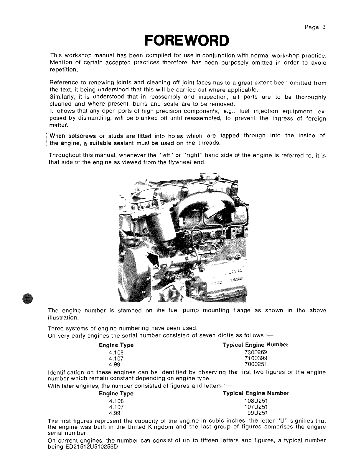
The
engine
number
is stamped on the fuel
pump
mounting
flange
as shown in
the
above
illustration.
Three systems
of
engine
numbering
have been used.
On
very early engines the serial
number
consisted
of
seven
digits
as
follows
:-
Engine Type
Typical
Engine
Number
4.108 7300269
4.107 7100399
4.99 7000251
Identification
on these
engines
can be
identified
by
cbserving
the
first
two
figures
of
the
engine
number
which
remain
constant
depending
on
engine
type.
With
later
engines, the
number
consisted
of
figures
and
letters
Engine Type
Typical
Engine
Number
4.108 108U251
4.107 107U251
4.99 99U251
The first
figures
represent the
capacity
of
the
engine
in
cubic
inches,
the
letter
"U"
signifies
that
the
engine
was
built
in the
United
Kingdom
and
the
last
group
of
figures
comprises
the engine
serial number.
On
current
engines, the
number
can
consist
of
up
to
fifteen
letters
and
figures, a typical
number
being ED21512U510256D
Page 4

Page4
~
Safety precautions
THESE SAFETY PRECAUTIONS ARE IMPORTANT. Reference must also be made to the local
regulations in the country of operation.
Do not use these engines in marine applications.
Do
not
change the specification
of
the engine.
Do
not
smoke when you
put
fuel in the tank.
Clean away any fuel which has fallen and move material which has fuel contamination to a safe
place.
Do
not
put
fuel in the tank during engine
operation
(unless really necessary).
Never clean, lubricate
or
adjust the engine
during
operation (unless you have had the
correct
training when extreme caution must be used to prevent
injury).
Do not make any adjustments you do not understand.
Ensure the engine is not in a position to cause a concentration of toxic emissions.
Persons in the area must be kept clear during
engine
and equipment
or
vehicle operation.
Do not permit loose clothing
or
long
hair
near parts which move.
Keep away from parts which turn during operation. Note that fans can
not
be seen clearly while
the engine is run.
Do not run the engine with any safety guards removed.
Do not remove the radiator cap while the
engine
is hot and the
coolant
is
under
pressure as
dangerous
hot
coolant
can be discharged.
Do
not
use salt water in the cooling system
or
any
other
coolant which can cause corrosion.
Keep sparks
or
fire away from batteries (especially during charge)
or
combustion can occur.
The battery fluid can burn and is also dangerous to the skin and especially the eyes.
Disconnect the battery terminals before you make a repair to the electrical system.
Only one person must be in control of the engine.
Ensure the engine is only operated from the
control
panel
or
operators position.
If your skin comes into
contact
with high pressure fuel,
get
medical assistance immediately.
Diesel fuel can cause skin damage to some persons. Use protection on the hands (gloves
or
special skin protection
solutions).
Do
not
move equipment unless the brakes are in
good
condition.
Ensure that the transmission drive control is in
"Out
of
Drive"
position
before the engine is
started.
Fit only
correct
Perkins Parts.
Page 5
CONTENTS
ENGINE VIEWS
TECHNICAL DATA
OPERATING AND MAINTENANCE
FAULT FINDING
CYLINDER HEAD
PISTONS AND CONNECTING RODS
CYLINDER BLOCK AND LINERS
CRANKSHAFT AND MAIN BEARINGS
TIMING CASE AND DRIVE
TIMING
LUBRICATING SYSTEM
COOLING SYSTEM
AIR CLEANERS AND FUEL SYSTEM
FLYWHEEL AND HOUSING
ELECTRICAL EQUIPMENT
ENGINES
FOR
REFRIGERATION UNITS
APPROVED LUBRICATING OILS
APPROVED SERVICE TOOLS
INDEX
A
B
C
D
E
F
G
H
J
K
L
M
N
P
Q
R
Appendix
Page 5
Page 6
Page 6
EXAMPLES
OF
SERVICE
FACILITIES
Service
If any problems
occur
with
your
engine
or
the components fitted to it,
your
Perkins
distributor
can make the necessary repairs and will ensure that only the
correct
parts are fitted and
that
the
work
is
done
correctly.
Certain
components
can be supplied by
your
Perkins
distributor
through
the Perkins
Power
exchange
system. These will enable you to red uce the
cost
of
some repairs.
Extended Warranty
The
engine
warranty period can be extended to
two
years. For details,
get
in
contact
with
your
nearest Perkins
distributor.
Service Literature
Users handbooks and other service
publications
are available from
your
Perkins
distributor
at a
nominal cost.
Training
Local training on
correct
engine operation,
overhaul
and service is available
at
some Perkins
distributors. If
special
training is needed,
your
Perkins
distributor
can give
details
on
how
to
get
this at the
Product
Education Department, Peterborough,
or
other main centres.
Page 7

SECTION A
Engine
Views
Page 8
ENGINE
VIEWS-A.2
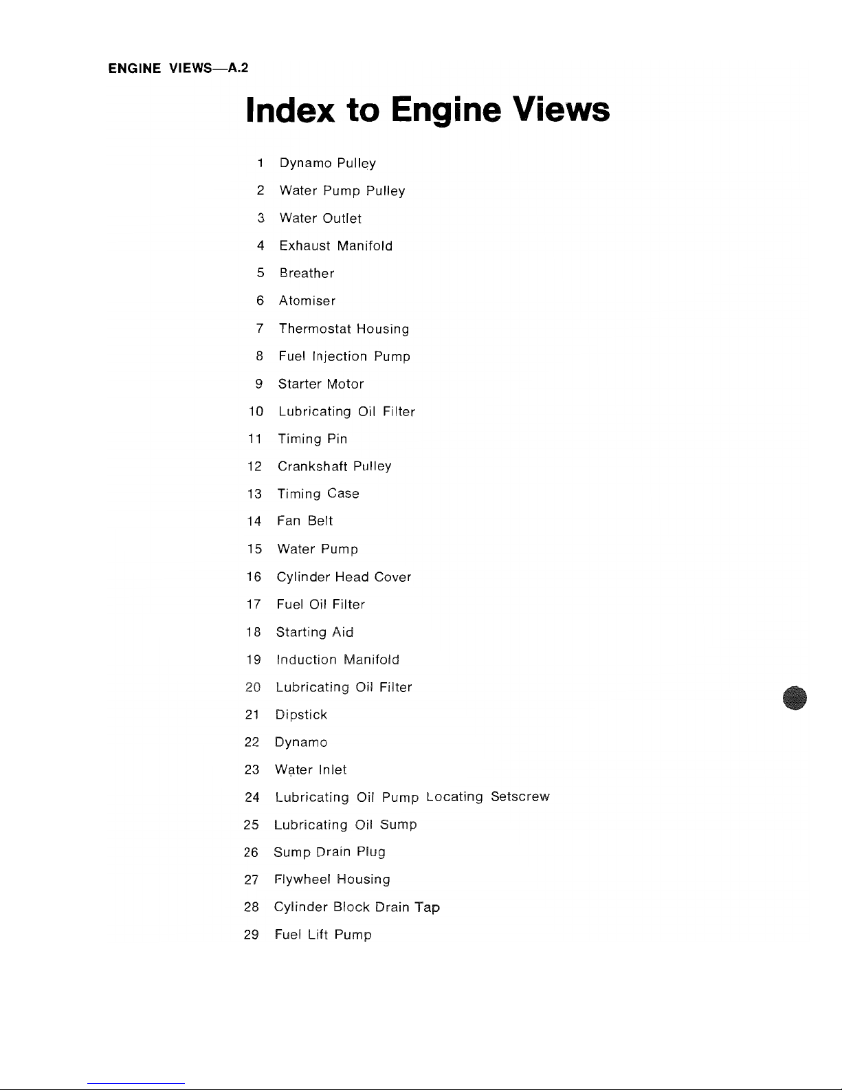
Index to Engine Views
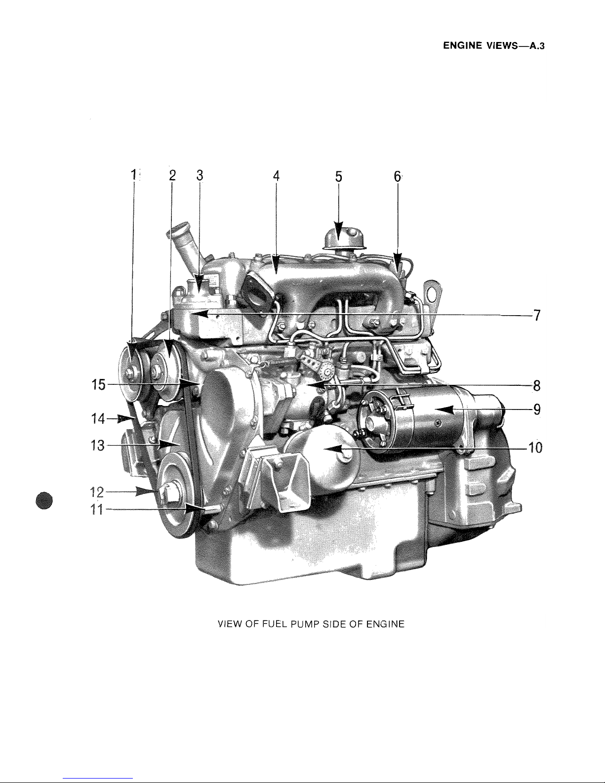
Dynamo Pulley
2 Water
Pump
Pulley
3 Water
Outlet
4
Exhaust
Manifold
5
Breather
6
Atomiser
7
Thermostat
Housing
8 Fuel
Injection
Pump
9 Starter
Motor
10
Lubricating
Oil
Filter
11
Timing Pin
12
Crankshaft
Pulley
13
Timing
Case
14 Fan
Belt
15 Water
Pump
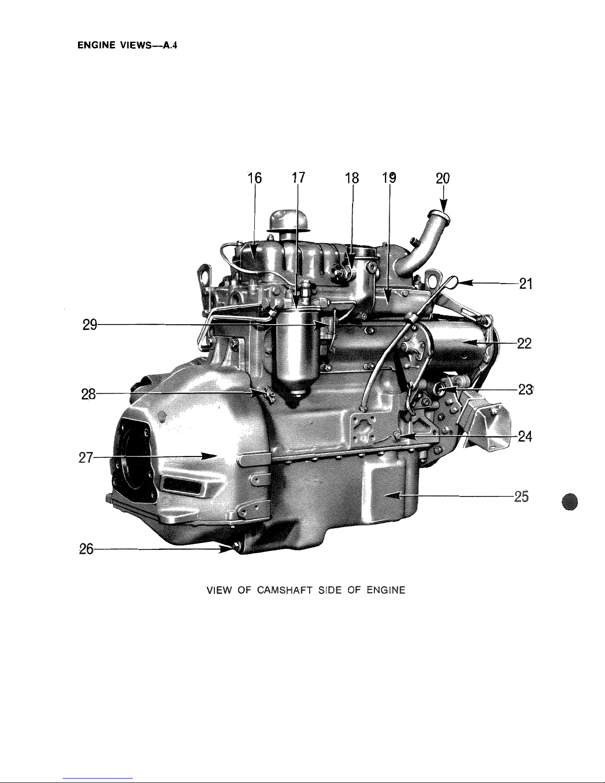
16
Cylinder
Head Cover
17
Fuel Oil
Filter
18 Starting
Aid
19
Induction
Manifold
20 Oil Filter
21
Dipstick
22 Dynamo
23 W?ter
Inlet
24
Lubricating
Oil Pump
Locating
Setscrew
25
Lubricating
Oil
26
Sump
Drain
Plug
27 Flywheel
Housing
28
Cylinder
Block
Drain
Tap
29 Fuel
Lift
Pump
Page 9
ENGINE
VIEWS-A.3
2 3
4
5
-----7
9
VIEW OF FUEL PUMP SIDE OF ENGINE
Page 10
ENGINE
VIEWS-A.4
1
17
1
20
VIEW OF CAMSHAFT SIDE OF ENGINE
Page 11
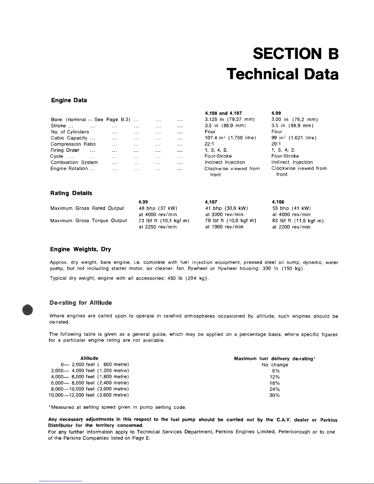
Engine Data
Bore
(nominal-
See Page B.3) ...
Stroke
...
No.
of
Cylinders
Cubic
Capacity
...
Compression Ratio
Firing
Order
Cycle
'"
Combustion
System
Engine Rotation
...
Rating Details
4.99
Maximum
Gross
Rated
Output
Maximum
Gross
Torque
Output
Engine Weights, Dry
48
bhp
(37 kW)
at 4000
rev/min
73 Ibf
ft
(10,1 kgf
m)
at 2250
rev/min
SECTION B
Technical Data
4.108 and 4.107
3.125 in (79,37
mm)
3.5 in (88,9
mm)
Four
107.4 in3 (1,760
litre)
22:1
1,3,4,2.
Four-Stroke
Indirect
Injection
Clockwise
viewed from
front
4.107
41
bhp
(30,6
kW)
at 3000
rev/min
79 Ibf
ft
(10,9
kgf
m)
at 1900
rev/min
4.99
3.00 in (76,2
mm)
3.5 in (88,9
mm)
Four
99 in3 (1,621
litre)
20:1
1, 3, 4, 2.
Four-Stroke
Indirect
Injection
Clockwise
viewed
from
front
4.108
55
bhp
(41 kW)
at 4000
rev/min
83 Ibf
ft
(11,5
kgf
m)
at 2200
rev/min
Approx.
dry
weight, bare engine, i.e.
complete
with
fuel
injection
equipment,
pressed steel
oil
sump, dynamo,
water
pump,
but
not
including
starter
motor,
air
cleaner, fan,
flywheel
or
flywheel housing: 330 Ib (150
kg).
Typical
dry
weight, engine with all accessories: 450 Ib
(204
kg).
Where
engines
are
called
upon to
operate
in rarefied
atmospheres
occasioned
by altitude,
such
engines
should
be
de-rated.
The
following
table
is given as a general guide,
which
may
be
applied
on a
percentage
basis,
where
specific
figures
for a particular
engine
rating are not available.
Altitude
0-
2,000 feet ( 600
metre)
2,000-
4,000
feet
(1,200
metre)
4,000-
6,000
feet
(1,800
metre)
6,000-
8,000 feet (2,400
metre)
8,000-10,000
feet
(3,000
metre)
10,000-12,000
feet
(3,600
metre)
* Measured
at
setting
speed given in
pump
setting
code.
Maximum
fuel
delivery
de-rating*
No
change
6%
12%
18%
24%
30%
Any
necessary
adjustments
in
this
respect
to
the fuel
pump
should
be
carried
01.11
by
the C.A.V.
dealer
or
Perkins
Distributor
for
the
territory
concerned.
For any
further
information
apply
to
Technical
Services
Department,
Perkins
Engines
Limited,
Peterborough
or
to one
of
the Perkins
Companies
listed on Page 2.
Page 12
TECHNICAL
DATA-B.2
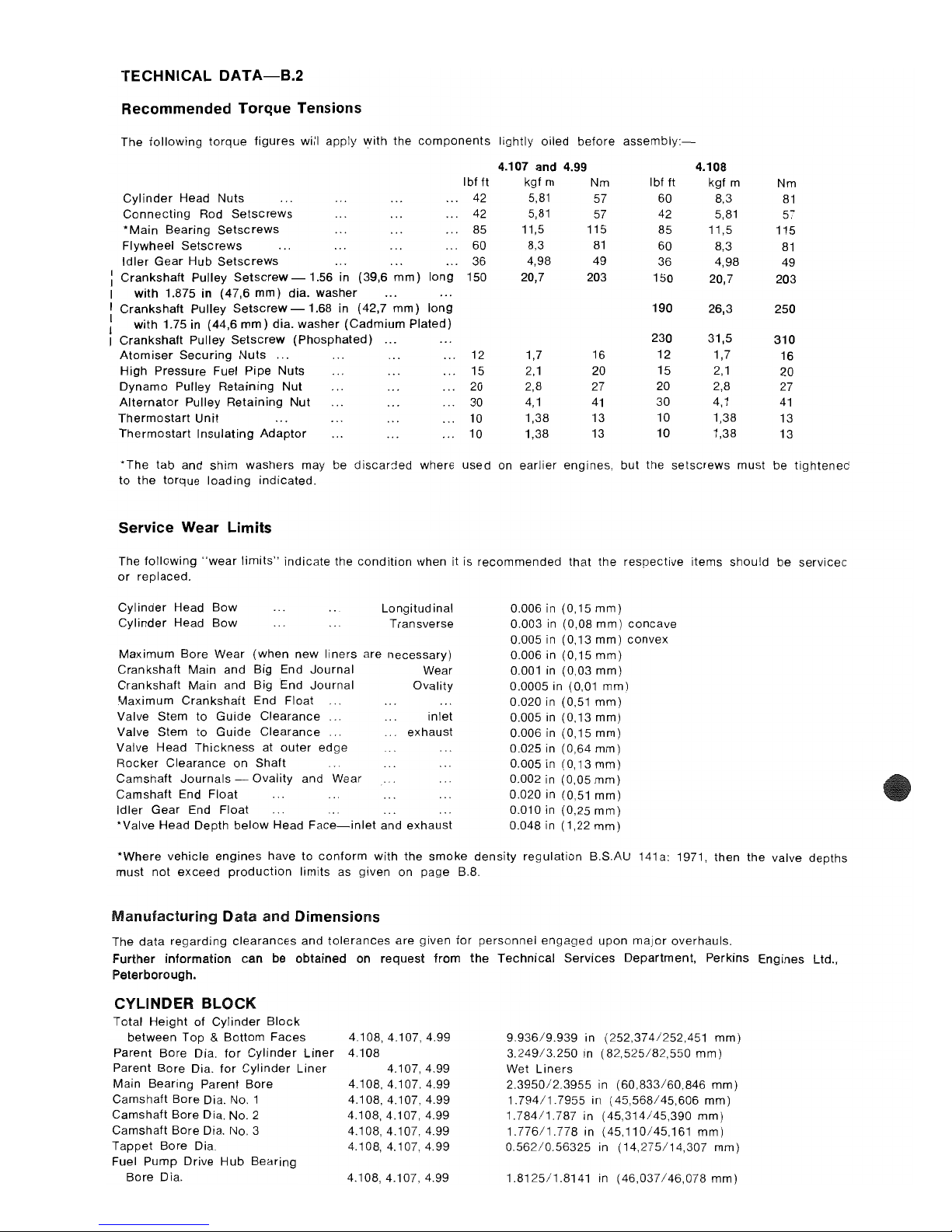
Recommended Torque Tensions
The
following
torque
figures
will
apply
with
the
components
lightly oiled
before
assembly:-
4.107 and
4.99 4.108
Ibf
ft
kgf m
Nm
Ibf
ft
kgf
m
Nm
Cylinder
Head
Nuts
42
5,81
57 60 8,3
81
Connecting
Rod
Setscrews
42
5,81
57
42
5,81
57
*
Main
Bearing
Setscrews
85
11,5 115
85 11,5
115
Flywheel
Setscrews
60
8,3
81
60
8,3
81
Idler
Gear
Hub
Setscrews
36
4,98 49 36 4,98
49
Crankshaft
Pulley
Setscrew-1.56
in (39,6
mm)
long
150 20,7
203
150 20,7
203
with
1.875
in
(47,6
mm)
dia.
washer
Crankshaft
Pulley
Setscrew
-1.68
in (42,7
mm)
long
190
26,3
250
with
1.75 in (44,6
mm)
dia.
washer
(Cadmium
Plated)
Crankshaft
Pulley
Setscrew
(Phosphated)
230
31,5
310
Atomiser
Securing
Nuts
.,
.
12 1,7
16
12
1,7
16
High
Pressure Fuel
Pipe
Nuts 15
2,1
20
15
2,1
20
Dynamo
Pulley
Retaining
Nut
20 2,8 27
20 2,8
27
Alternator
Pulley
Retaining
Nut
30
4,1
41
30
4,1
41
Thermostart
Unit
10 1,38 13
10 1,38
13
Thermostart
Insulating
Adaptor
10 1,38 13
10
1,38
13
*The
tab
and
shim
washers
may be
discarded
where
used
on
earlier
engines, but
the
setscrews
must be
tightened
to
the
torque
loading
indicated.
Service Wear Limits
The
following
"wear
limits"
indicate
the
condition
when it is
recommended
that
the
respective
items
should
be
servicec
or
replaced.
Cylinder
Head
Bow
Cylinder
Head
Bow
Longitud
inal
Transverse
Maximum
Bore Wear
(when
new
liners
are
necessary)
Crankshaft
Main and Big End
Journal
Wear
Crankshaft
Main and Big End
Journal
Ovality
Maximum
Crankshaft
End Float
Valve Stem to
Guide
Clearance
inlet
Valve Stem to
Guide
Clearance
Valve Head
Thickness
at
outer
edge
Rocker
Clearance
on Shaft
Camshaft
Journals
Ovality
and Wear
Camshaft
End Float
Idler
Gear End
Float
exhaust
*Valve Head Depth
below
Head
Face-inlet
and
exhaust
0.006 in (0,15
mm)
0.003
in
(0,08
mm)
concave
0.005 in (0,13
mm)
convex
0.006 in
(0,15mm)
0.001
in
(0,03
mm)
0.0005 in (0,01
mm)
0.020 in (0,51
mm)
0.005
in
(0,13
mm)
0.006
in
(0,15
mm)
0.025 in (0,64
mm)
0.005 in
(0,13mm)
0.002 in (0,05
mm)
0.020 in (0,51
mm)
0.010 in (0,25
mm)
0.048 in (1,22
mm)
*Where
vehicle
engines
have
to
conform
with
the
smoke
density
regulation
B.S.AU
141
a:
1971, then
the
valve
depths
must
not
exceed
production
limits
as given on page B.8.
Manufacturing
Data
and
Dimensions
The
data
regarding
clearances
and
tolerances
are
given for
personnel
engaged
upon
major
overhauls.
Further
information
can
be
obtained
on
request
from
the
Technical
Services
Department,
Perkins Engines Ltd.,
Peterborough.
CYLINDER BLOCK
Total
Height
of
Cylinder
Block
between
Top & Bottom
Faces
Parent
Bore
Dia.
for
Cylinder
Liner
Parent Bore Dia.
for
Cylinder
Liner
Main Bearing Parent
Bore
Camshaft
Bore
Dia.
No.1
Camshaft Bore Dia.
No.2
Camshaft
Bore
Dia.
No.3
Tappet
Bore Dia.
Fuel
Pump
Drive
Hub
Bearing
Bore
Dia.
4.108,4.107,4.99
4.108
4.107,4.99
4.108,4.107,4.99
4.108,4.107,4.99
4.108,4.107,4.99
4.108,4.107,4.99
4.108,4.107,4.99
4.108,4.107,4.99
9.936/9.939
in
(252,374/252,451
mm)
3.249/3.250
in
(82,525/82,550
mm)
Wet
Liners
2.3950/2.3955
in
(60,833/60,846
mm)
1.794/1.7955
in
(45,568/45,606
mm)
1.78411.787
in
(45,314/45,390
mm)
1.776/1.778
in
(45,110/45,161
mm)
0.562/0.56325
in
(14,275/14,307
mm)
1.812511.8141 in
(46,037/46,078
mm)
Page 13
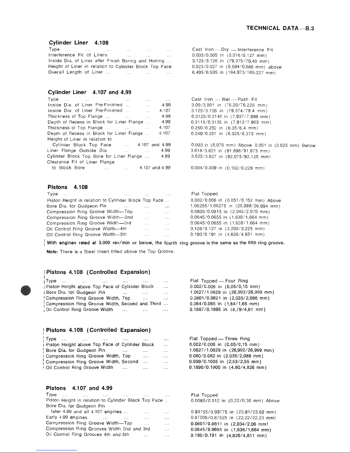
Cylinder Liner 4.108
Type
Interference
Fit
of
Liners
Inside
Dia. of
Liner
after Finish Boring and Honing
Height
of
Liner
in relation to Cylinder
Block
Top Face
Overall Length
of
Liner
Cylinder Liner 4.107 and 4.99
Type
Inside
Dia.
of
Liner
Pre-Finished
4.99
Inside
Dia.
of
Liner Pre-Finished 4.107
Thickness
of Top
Flange.
4.99
Depth of Recess in
Block
for Liner
Flange.
4.99
Thickness
of Top
Flange..
4,107
Depth of Recess in
Block
for
Liner Flange 4,107
Height
of Liner
in
relation to
Cylinder
Block
Top
Face 4,107 and 4.99
Liner
Flange Outside Dia. 4.99
Cylinder
Block
Top Bore for
Liner
Flange 4.99
Clearance Fit of
Liner
Flange
to
Block
Bore 4.107 and 4.99
Pistons 4.108
Type
Piston Height in relation to Cylinder
B!ock
Top
Face.
Bore Dia.
for
Gudgeon
Pin
Compression Ring Groove
Width-Top
Compression Ring Groove
Width-2nd
Compression Ring Groove
Width-3rd
Oil Control Ring Groove
Width-4th
Oil Control Ring Groove
Width-5th
i With
engines
rated at 3.000
rev/min
or
below,
the
fourth
Note: There is a Steel Insert fitted above the Top Groove.
I Pistons 4.108
(Controlled
Expansion)
I
IType
...
I Piston
Height
above Top Face of
Cylinder
Block
I Bore Dia.
for
Gudgeon Pin
I Compression Ring Groove Width,
Top
1 Compression Ring Groove Width,
Second
and
Third
.. .
I Oil Control Ring Groove Width
...
...
..
.
: Pistons 4.108
(Controlled
Expansion)
: Type
...
I Piston Height above Top Face
of
Cylinder
Block
:
Bore
Dia.
for
Gudgeon Pin
I CompreSSion Ring Groove Width,
Top
: Compression Ring Groove Width,
Second
I Oil Control Ring Groove Width
Pistons 4.107 and 4.99
Type
Piston Height in relation to
Cylinder
Block
Top Face ..
Bore Dia.
for
Gudgeon
Pin
later 4.99 and all 4.107
engines
...
Early 4.99
engines
Compression Ring Groove
Width-Top
Compression Ring Grooves Width 2nd and 3rd
Oil Control Ring Grooves 4th and 5th
TECHNICAL
DATA-B.3
Cast Iron - Dry -
Interference
Fit
0,003/0.005
in
(0,076/0.127
mm)
3.12513.126
in
(79,375179,40
mm)
0.023/0.027
in
(0,584/0,686
mm)
above
6.495/6.505
in
(164,973/165,227
mm)
Cast Iron - Wet Push Fit
3,00/3.001
in
(7620176.225
mm)
3.125/3,126
in
(79,374179.4
mm)
0.312510.3145
in
(7,93717,988
mm)
0.3115/0.3135
in
(7,91217,963
mm)
0.25010,252
in
(6.35/6,4
mm)
0.249/0,251
in
(6.325/6,375
mm)
0.003 in (0,076 mm) Above. 0.001
in
(0.025 mm)
Below
3.61813.621
in
(91.898/91,973
mm)
3.625/3,627
in
(92,075/92,125
mm)
0,00410.009
in
(0,102/0.229
mm)
Flat Topped
0.00210.006
in
(0,051/0.152
mm)
Above
1.06255/1.06275
in
(26,989/26.994
mm)
0.080510.0815
in
(2,045/2,070
mm)
0.0645/0.0655
in
(1,638/1,664
mm)
0.0645/0.0655
in
(1,638/1,664
mm)
0.126/0.127
in
(3.200/3,225
mm)
0.19010.191 in
(4,826/4.851
mm)
ring
groove
is
the
same as
the
fifth
ring
groove.
Flat
Topped
- Four Ring
0.002/0.006
in
(0,05/0,15
mm)
1.062711.0629
in
(26,992/26,999
mm)
0.080110.0821
in
(2,035/2,086
mm)
0.06410.065
in
(1,64/1,65
mm)
0.1887/0.1895
in (4,7914,81
mm)
Flat
Topped -Three
Ring
0.002/0.006
in
(0,05/0,15
mm)
1.062711.0629
in
(26,992/26,999
mm)
0.080/0.082
in
(2,035/2,086
mm)
0.09910.1005
in
(2,53/2,55
mm)
0.1890/0.1900
in
(4,8014,826
mm)
Flat
Topped
0.0085/0.012
in
(0,2210,30
mm)
Above
0.93755/0.93775
in
(23,81/23,82
mm)
0.87505/0.87525
in
(22,22122,23
mm)
0.0801/0.0811
in
(2,034/2,06
mm)
0.0645/0.0655
in
(1,638/1,664
mm)
0.190/0.191
in
(4,826/4,851
mm)
Page 14
TECHNICAL
DATA-B.4
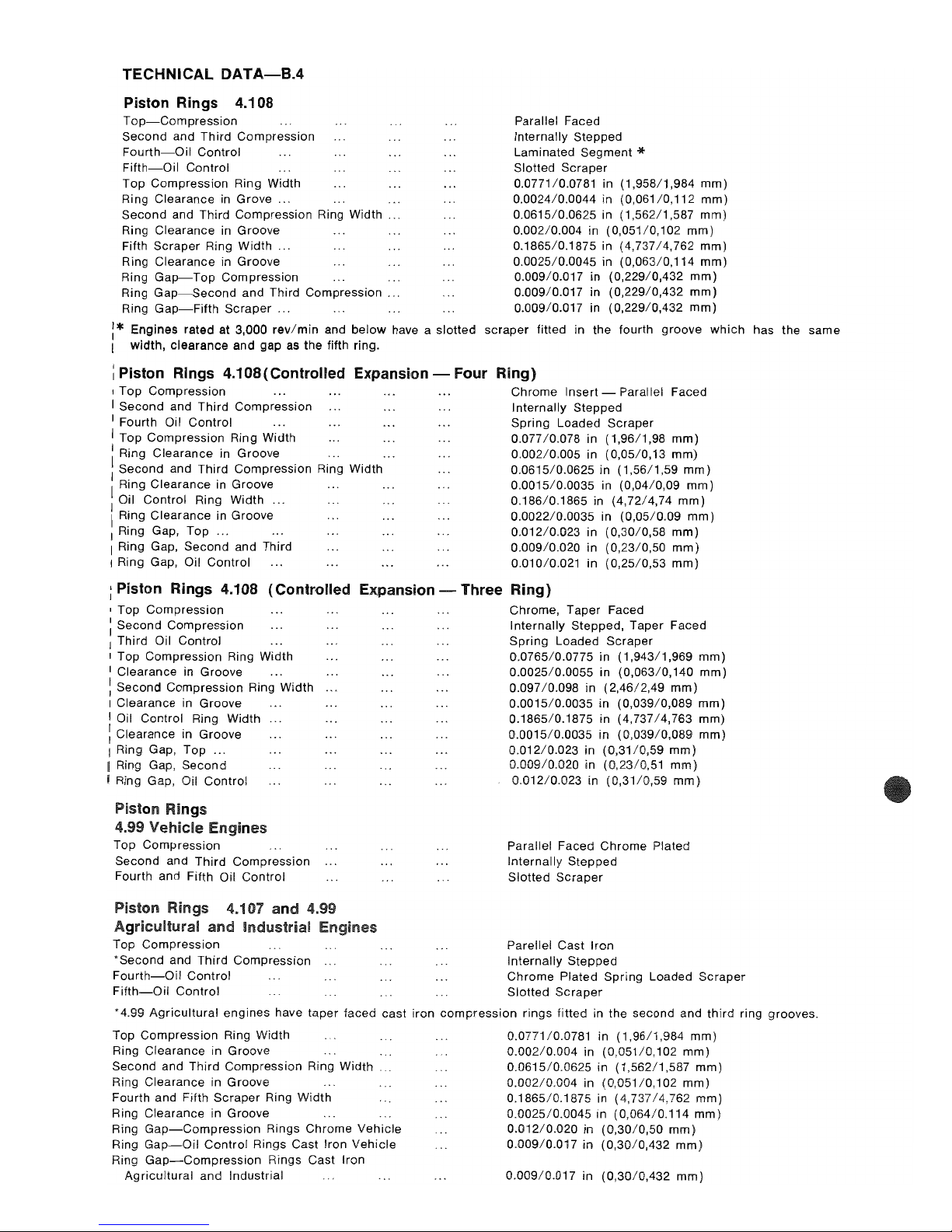
Piston Rings 4.108
Top-Compression
Second and Third Compression
Fourth-Oil
Control
Fifth-Oil
Control
Top Compression Ring Width
Ring Clearance in
Grove
...
Second and Third Compression Ring Width
Ring Clearance in
Groove
Fifth
Scraper
Ring Width
...
Ring Clearance in
Groove
Ring
Gap-Top
Compression
Ring
Gap-Second
and Third Compression .
Ring
Gap-Fifth
Scraper
...
Parallel Faced
Internally Stepped
Laminated Segment
'*
Slotted Scraper
0.0771/0.0781 in
(1,958/1,984
mm)
0.0024/0.0044 in
(0,061/0,112
mm)
0.0615/0.0625 in (1,562/1,587
mm)
0.00210.004 in
(0,051/0,102
mm)
0.1865/0.1875 in
(4,737/4,762
mm)
0.0025/0.0045 in
(0,063/0,114
mm)
0.00910.017 in
(0,229/0,432
mm)
0.00910.017 in
(0,229/0,432
mm)
0.00910.017 in
(0,229/0,432
mm)
:*
Engines rated at 3,000
revlmin
and
below
have a slotted scraper fitted in the fourth
groove
which
has the same
I width, clearance and gap as the fifth ring.
: Piston Rings
4.108(Controlied
Expansion -
Four
Ring)
, Top Compression
I Second and Third Compression
I Fourth Oil Control
I Top Compression Ring Width
I Ring Clearance in
Groove
...
: Second and Third Compression Ring Width
Ring Clearance in
Groove
I Oil Control Ring Width
...
I Ring Clearance in Groove
J Ring Gap, Top
...
. ..
I Ring Gap, Second and Third
I Ring Gap, Oil Control
Chrome Insert - Parallel Faced
Internally Stepped
Spring Loaded Scraper
0.077/0.078
in
(1,96/1,98
mm)
0.002/0.005 in
(0,05/0,13
mm)
0.0615/0.0625 in (1,5611,59
mm)
0.0015/0.0035
in (0,0410,09
mm)
0.186/0.1865
in
(4,72/4,74
mm)
0.0022/0.0035
in (0,0510.09
mm)
0.012/0.023
in
(0,30/0,58
mm)
0.009/0.020
in
(0,23/0,50
mm)
0.010/0.021 in
(0,25/0,53
mm)
: Piston Rings 4.108
(Controlled
Expansion -
Three
Ring)
I Top Compression
: Second Compression
I Third Oil Control
I Top Compression Ring Width
I Clearance in
Groove
...
: Second Compression Ring Width
I Clearance in
Groove
I Oil Control Ring Width
: Clearance in
Groove
I Ring Gap, Top
...
I Ring Gap, Second
I Ring Gap, Oil Control
Piston Rings
4.99
Vehicle
Top Compression
Second and Third Compression
Fourth and Fifth Oil Control
Piston Rings 4.107
and
4.99
and
Industrial
Top Compression
'Second
and Third Compression
Fourth-Oil
Control
Fifth-Oil
Control
Chrome,
Taper
Faced
Internally Stepped, Taper Faced
Spring Loaded Scraper
0.0765/0.0775
in
(1,943/1,969
mm)
0.0025/0.0055
in
(0,063/0,140
mm)
0.097/0.098
in
(2,46/2,49
mm)
0.0015/0.0035
in
(0,039/0,089
mm)
0.1865/0.1875
in
(4,737/4,763
mm)
0.0015/0.0035
in
(0,039/0,089
mm
0.01210.023 in
(0,31/0,59
mm)
0.009/0.020
in
(0,23/0,51
mm
0.012/0.023
in
(0,31/0,59
mm
Parallel Faced Chrome Plated
Internally Stepped
Slotted
Scraper
Parellel Cast Iron
Internally Stepped
Chrome
Plated Spring Loaded
Scraper
Slotted
Scraper
•
4.99
Agricultural
engines have taper faced cast iron
compression
rings fitted in the second and
third
ring grooves.
Top Compression Ring Width
Ring Clearance in
Groove
Second and
Third
Compression Ring
Width.
Ring Clearance in Groove
Fourth and Fifth Scraper Ring Width
Ring Clearance in Groove
Ring
Gap-Compression
Rings Chrome Vehicle
Ring
Gap-Oil
Control Rings Cast Iron Vehicle
Ring
Gap-Compression
Rings Cast Iron
Agricultural and Industrial
0.0771/0.0781 in
(1,96/1,984
mm)
0.002/0.004
in
(0,051/0,102
mm)
0.0615/0.0625
in
(1,562/1,587
mm)
0.00210.004 in
(0,051/0,102
mm)
0.1865/0.1875
in (4,73714,762
mm)
0.0025/0.0045
in
(0,064/0.114
mm)
0.01210.020 in
(0,30/0,50
mm)
0.009/0.017
in
(0,30/0,432
mm)
0.009/0.017
in
(0,30/0,432
mm)
Page 15
Gudgeon
Pin 4.108
Type
Outside
Dia.
of
Gudgeon
Pin
Length
of
Gudgeon Pin
Fit
in Piston Boss
Gudgeon
Pin 4.107 and 4.99
Type
Outside Dia.
of
Gudgeon
Pin
(Later
Engines)
Outside
Dia.
of
Gudgeon
Pin
(Earlier
Engines)
Fit
in Piston Boss
Small
End Bush 4.108
Type
Length
of
Small
End
Bush
Outside
Dia.
of
Small
End Bush
Inside
Dia.
before
Reaming
Inside
Dia.
after
Reaming
Clearance
between Small End Bush and Gudgeon Pin
Small
End Bush 4.107 and 4.99
Type
Length
of
Small End Bush
Outside Dia.
of
Small End Bush
on
later
4.99 and all 4.107 engines
Early 4.99
engines
Inside
Dia.
after
Reaming on
later
4.99
and
a/l 4.107 engines
Early 4.99 engines
Clearance
between Small End Bush and Gudgeon Pin
TECHNICAL
DATA-B.S
Fully Floating
1.0625/1.0627 in
(26,987/26,993
mm)
2,673/2,687 in
(67,894/68,250
mm)
Transition
Fully Floating
0.9375
in/0.9377
in
(23,812/23,817
mm)
0.875/0.8752 in
(22,225/22,23
mm)
Transition
Steel Backed, Lead
Bronze
Lined
0.935/0.955
in
(23,749/24,257
mm)
1.221/1.222
in
(31,013/31,039
mm)
1.0495/1.0545 in
(26,657/26,784
mm)
1.06315/1.0632
in
(27,004/27,005
mm)
0.00045/0.0007 in
(0,0114/0,0178
mm)
Steel Backed, Lead
Bronze
Lined
0.865/0.885
in
(22,00/22,48
mm)
1.06511.066 in
(27,05/27,08
mm)
1.0025/1.0035
in (25,46125,49 mm)
0.9382/0.93875
in
(23,83/23,84
mm)
0.8757/0.87625
in
(22,24/22,26
mm)
0.0005/0.00125
in (0,0110,03
mm)
Note. Bushes
to
be reamed
to
suit respective Gudgeon Pins, and are
provided
with
a reaming allowance.
nSI::ti§11n Rod 4.108
Type 'H'
Section
Cap
Location
to
Connecting
Rod
Big End Parent
Bore
Dia.
Small End Parent Bore Dia.
Length from Centre Line
of
Big End
to
Centre Line
of
Small End
Big End
Setscrew
Connecting
Rod End Float
Connecting
Rod 4.107 and 4.99
Type
Cap
Location
to
Connecting
Rod
Big End Parent Bore Dia.
Small End Parent Bore Dia.
on
later
4.99 and all 4.107 engines
Early 4.99
engines
Length from Centre Line
of
Big End to Centre Line
of
Small End
Big End Setscrew
Connecting
Rod End Float
on
later
4.99
and
all 4.107 engines
Early 4.99 engines
Serrations, Offset 45
to
the Horizontal
2.146/2.1465 in
(54,508/54,521 mm)
1.21875/1.21975 in (30,956/30,981
mm)
6.217/6.219
in
(157,912/157,963
mm)
0.375 in
(i
in)
U.N.F.
0.006510.0105 in
(0,165/0,267
mm)
'H'
Section
Serrations,
Offset
45'
to
the
Horizontal
2. i 46/2.1465
in (54,508/54,521 mm)
1.0625/1.0635
in (26,99/27,01
mm)
1.00/1.001
in
(25,4/25,43mm)
6.405/6.407
in
(162,69/162,74
mm)
0.375 in
(i
in)
U.N.F.
0.0065/0.0105
in (0,1610,27
mm)
0.0075/0.0105
in
(0,19/0,27
mm)
Page 16
TECHNICAL
DATA-B.G
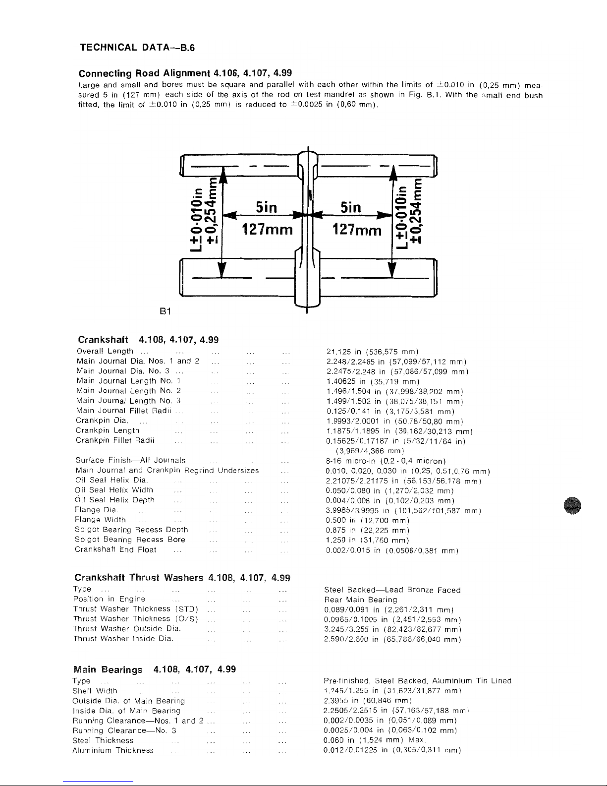
Connecting Road Alignment
4.108,4.107,4.99
Large
and
small
end
bores
must be
square
and
parallel
with
each
other
within
the
limits
of
::'::0.010 in
(0,25
mm)
mea-
sured
5 in (127
mm)
each
side
of
the
axis
of
the
rod
on
test
mandrel
as
shown
in Fig. B.1.
With
the
small
end
bush
fitted, the
limit
of
::'::0.010 in (0,25
mm)
is
reduced
to
::'::0.0025 in (0,60
mm).
-
--
Ej~
.=
E
=
-.::t
Sin
.-It')
-
..
=N
-
~
00
127mm
+1
+.
...J
"
B1
Crankshaft
4.108,4.107,4.99
Overall
Length
Main
Journal
Dia. Nos. 1 and 2
Main
Journal
Dia.
No.3
Main
Journal
Length
No.
Main
Journal
Length
No.2
Main
Journal
Length
NO.3
Main
Journal
Fillet
Radii
Crankpin
Dia.
Crankpin
Length
Crankpin
Fillet
Radii
Surface
Finish-All
Journals
Main
Journal
and
Crankpin
Regrind
Undersizes
Oil Seal
Helix
Dia.
Oil Seal Helix
Width
Oil Seal
Helix
Depth
Flange
Dia.
Flange
Width
Spigot
Bearing
Recess Depth
Spigot
Bearing
Recess
Bore
Crankshaft
End Float
Crankshaft
Thrust
Washers 4.108,
4.1
Type
Position
in
Engine
Thrust
Washer
Thickness
(STD)
Thrust
Washer
Thickness
(O/S)
Thrust
Washer
Outside
Dia.
Thrust
Washer
Inside
Dia.
Main
Bearings
4.108, 4.101, 4.99
Type
Shell
Width
Outside
Dia.
of
Main
Bearing
Inside
Dia.
of
Main
Bearing
Running
Clearance-Nos. 1 and
2 .
Running
Clearance-No.
3
Steel
Thickness
Aluminium
Thickness
,;
i..-
4.99
....
~
-
c:
E
I
.-
E
Sin
=-.::t
--
-
'-It')
-
..
C?N
127mm
=0
+1+.
t-.
...J
'f
-
:..,...
21.125 in (536,575
mm)
2.248/2.2485
in
(57,099/57,112
mm)
2.2475/2.248
in
(57,086/57,099
mm)
1.40625 in (35,719
mm)
1.496/1.504
in
(37,998/38,202
mm)
1.499/1.502
in
(38.075/38,151
mm)
0.12510.141 in
(3,175/3,581
mm)
1.9993/2.0001
in
(50,78/50,80
mm)
1.1875/1.1895
in
(30.162/30,213
mm)
0.15625/0.17187
in
(5/32/11/64
in)
(3,969/4,366
mm)
8-16
micro-in
(0,2
- 0,4
micron)
0.010.0.020,0.030
in (0,25, 0.51.0.76
mm)
2.21075/2.21175
in
(56,153/56.178
mm)
0.050/0.080
in
(1,270/2,032
mm)
0.004/0.008
in
(0,102/0.203
mm)
3.9985/3.9995
in
(101,562/101,587
mm)
0.500 in (12,700
mm)
0.875 in (22,225
mm)
1.250 in (31,750
mm)
0.002/0.015
in
(0.0508/0.381
mm)
Steel
BaCked-Lead
Bronze
Faced
Rear
Main
Bearing
0.089/0.091
in
(2,261/2,311
mm)
0.0965/0.1005
in
(2,451/2,553
mm)
3.24513.255 in
(82,423/82.677
mm)
2.590/2.600
in
(65.786/66,040
mm)
Pre-finished,
Steel
Backed.
Aluminium
Tin
Lined
1.245/1.255
in
(31.623/31.877
mm)
2.3955 in (60,846
mm)
2.2505/2.2515
in
(57,163/57,188
mm)
0.002/0.0035
in
(0.051/0,089
mm)
0.0025/0.004
in
(0,063/0.102
mm)
0.060 in (1,524
mm)
Max.
0.01210.01225
in
(0.305/0,311
mm)
Page 17
Connecting Rod Bearings 4.108, 4.107, 4.99
Type
Shell
Width
Outside Dia. of Can. Rod Bearing .
Inside Dia.
of
Can. Rod Bearing
Running Clearance
Steel
Thickness
.
Aluminium
Thickness
Camshaft 4.108,4.107,4.99
No. 1
Journal
Length
No.1
Journal
Dia.
No.1
Cylinder
Block
Camshaft Bore Dia.
No. 1
Journal
Running Clearance
No. 2
Journal
Length
No. 2
Journal
Dia.
No.2
Cylinder
Block
Camshaft Bore Dia.
No.2
Journal
Running Clearance
No. 3
Journal
Length
No. 3
Journal
Dia
NO.3
Cylinder
Block
Camshaft Bore Dia.
NO.3
Journal
Running Clearance
...
Cam
Lift
Oilways
for
Rocker Shaft Lubrication
Camshaft Thrust Plates 4.108, 4.107, 4.99
Type
Thrust Plate Outside Dia.
Cylinder
Block
Recess Dia. for Thrust Plate
Clearance Fit of Thrust Plate in Recess
Thrust Plate Inside Dia.
Thrust Plate Thickness
Cylinder
Block
Recess Depth
for
Thrust Plate
Thrust Plate
Height
in relation to
Cylinder
Block
Face
Camshaft End Float
Valve and Fuel Pump Timing
Refer to
later
section on timing (page
K.1
) .
CYLINDER HEAD
4.1
Overall Length of Cylinder Head
Overall Depth
of
Cylinder
Head
4.1
4.99
Skimming
Allowance
on
Cylinder
Head Face
Pressure
for
Water
Leakage Test
Valve Seat
Angle
Bore in
Cylinder
Head for Guide
Bore in
Cylinder
Head
for
Combustion
Chamber
Inserts
Depth of Bore in
Cylinder
Head for
Combustion Chamber Inserts
Combustion Chamber Inserts 4.108, 4.101,4.99
Outside Dia.
of
Insert
Depth
of
Insert
...
Height
of
Insert in relation
to
Cylinder
Head Face
Clerance Fit
of
Insert in
Cylinder
Head Bore
Method
of
Location
in
Cylinder
Head
Valve Guides
(inlet)
4.108,4.107,4.99
Inside Dia.
Outside Dia.
Interference fit
of
Guide in
Cylinder
Head Bore
Overall length of Guide ."
Guide Protrusion Above
Top
Face
of
Cylinder
Head
TECHNICAL
DATA-B.7
Pre-finished, Steel Backed,
Aluminium
Tin
Lined
0.870/0.880 in (22,098/22,325
mm)
2.1465 in (54,521
mm)
2.0015/2.0025 in (50,838/50,863
mm)
0.0014/0.0032 in (0,036/0,081
mm)
0.060 in (1,524
mm)
Max_
0.012/0.01225 in (0,305/0,311
mm)
1.347/1.351 in (34,214/34,315
mm)
1.791/1.792 in (45,491/45,517
mm)
1.794/1.7955 in (45,568/45,606
mm)
0.002/0.0045 in (0,051/0,114
mm)
1,250 in (31,750
mm)
1.781/1.782 in (45,237/45,26'3
mm)
1,784/1,787 in (45:314/45,390
mm)
0.002/0.006 in (0,051/0,152
mm)
1.000 in (25,400
mm)
1.773/1.774 in (45,034/45,060
mm)
1.776/1.778 in (45,110/45,161
mm)
0.002/0.005 in (0,051/0,127
mm)
0.2592/0.2622 in
(6,58/6,66
mm)
No. 2
Journal
180'
Oil Impregnated Sintered Iron
2.555/2.557 in (64,897/64,948
mm)
2.5585/2.5685 in (64,986/65,240
mm)
0.0015/0.013 in (0,038/0,330
mm)
1.500 in (38,100
mm)
0.160/0.162 in (4,060/4,115
mm)
0.158/0.164 in (4,009/4,166
mm)
0.004 in (0,102
mm)
above
or
below
0.003/0.009 in (0,076/0,228 mm)
20.000 in (508,000
mm)
2.617
/2.633
in (66,472/66,878
mm)
NIL-On
no
account
can the
cylinder
head face be
skimmed
20
Ibflin
2
(1,4
kgflcm2)
-138
kN/m
2
45°
0.4995/0.5005 in (12,687/12,713
mm)
1.250/1.252
in (31,750/31,801
mm)
0.373/0.376
in (9,474/9,550
mm)
1.248/1.249
in (31,699/31,724
mm)
0.374/0.375
in (9,499/9,525
mm)
0.002 in (0,051
mm)
above
or
below
0.001/0.004
in
(0,025/0,102
mm)
By
Cylinder
Block
Face and Expansion Washer
0.3141/0.3155 in (7,978/8,014
mm)
0.5021/0.5026 in (12,753/12,766
mm)
0.0016/0.0031 in (0,041/0,079
mm)
2.130
in
(54,102
mm)
6.800/0.815
in
(20,320/20,701
mm)
Page 18
TECHNICAL
DATA-B.B
Valve Guides (Exhaust)
4.10B,
4.107, 4.99
Inside Dia.
Outside
Dia.
Interference
fit
of
Guide in Cylinder Head Bore
Depth
of
Counterbore
Overall Length
of
Guide
'"
Guide
Protrusion above Top Face
of
Cylinder
Head
Valves (Inlet) 4.10B, 4,107, 4.99
Valve Stem Dia.
Clearance fit of Valve Stem in Guide
Valve Head Dia.
Valve Face Angle
Valve Head Depth
Below
Cylinder Head Face
Overall Length of Valve
Sealing Arrangement
Valve (Exhaust) 4.108,4.107,4.99
Valve Stem Dia.
Clearance Fit of Valve Stem in Guide
Valve Head Dia.
Valve Face Angle
Valve Head Depth
Below
Cylinder Head Face
Overall Length
of
Valve
Sealing Arrangement
Inner Valve Springs (where fitted)
Fitted Length
Load
at
Fitted Length
Fitted Position
Outer Valve Springs
Fitted Length
Load
at
Fitted Length
Fitted Position
4.10B,
4.107, 4.99
Rockel'
level's
4.108, 4.107, 4.99
Length between Centre Line of
Adjusting
Screw and
Centre Line of Rocker Shaft
Length between Centre Line of Rocker Lever
Pad and
Centre Line of Rocker Shaft
Inside Dia. of Rocker Lever Bore
Outside Dia. of Rocker Lever Bush
Interference Fit
of
Bush in Rocker Lever
Finished Inside Dia. of Rocker Lever Bush
Clearance of Rocker Lever Bush on
Rocker
Shaft
Valve Clearances 4.108, 4.107, 4.99
Clearance between Valve Stem Tip and Rocker Lever
Rocker
Shaft 4.108, 4.107, 4.99
Overall Length of Shaft
Outside Dia. of Shaft
Lubrication
Push Rods
Overall Length
Outside Dia.
4.108, 4.107, 4.99
0.3141/0.3155 in
(7,978/8,014
mm)
0.5021/0.5026 in
(12,753/12,766
mm)
0.001610.0031 in
(0,041/0,079
mm)
0.380 in (9,650
mm)
2.440 in (61,980
mm)
0.80010.815 in (20,320/20,701
mm)
0.312/0.313
in (7,92511,950
mm)
0.0011/0.0035 in
(0,028/0,089
mm)
1.410/1.414
in
(35,814/35,916
mm)
45'
0.028/0.039 in (0,711/0,991
mm)
4.592/4.608
in
(116,637/117,043
mm)
Rubber Oil Seal
0.3115/0.3125 in (7,91217,937
mm)
0.0016/0.004
in
(0,041/0,102
mm)
1.19111.195 in
(30,251/30,353
mm)
45°
0.021/0.032
in (0,53'3/0,813
mm)
4.60014.616 in
(116,840/117,246
mm)
No Seal fitted to Exhaust Valve
1.530 in (38,862
mm)
28.6 Ibf::'::: 2 Ibf (13,0 kgf::':::
0,91
kgf)
Damper Coil to
Cylinder
Head
1.780 in (45,212
mm)
56.0
Ibf::':::2.8
Ibf (25,4 kgf::':::1,27
kg!)
Damper Coil to
Cylinder
Head
1.042/1.058
in
(26,467/26,873
mm)
1.567/1.583
in
(39,802/40,208
mm)
0.71825/0.71950
in
(18,243/18,275
mm)
0.720510.7215 in
(18,301/18,326
mm)
0.00110.00325 in
(0,025/0,082
mm)
0.6245/0.62575
in
(15,862/15,894
mm)
0.00075/0.0035
in (0,01910,089 mm)
0.012 in (0,30
mm)
Cold
14.5625 in (369,887
mm)
0.62225/0.62375
in
(15,805/15,843
mm)
Oil Feed from
Cylinder
Head through Central
Passage
to
Individual
Rocker Levers
8.527/8.560
in
(216,58/217,42
mm)
0.250 in (6,350
mm)
Page 19
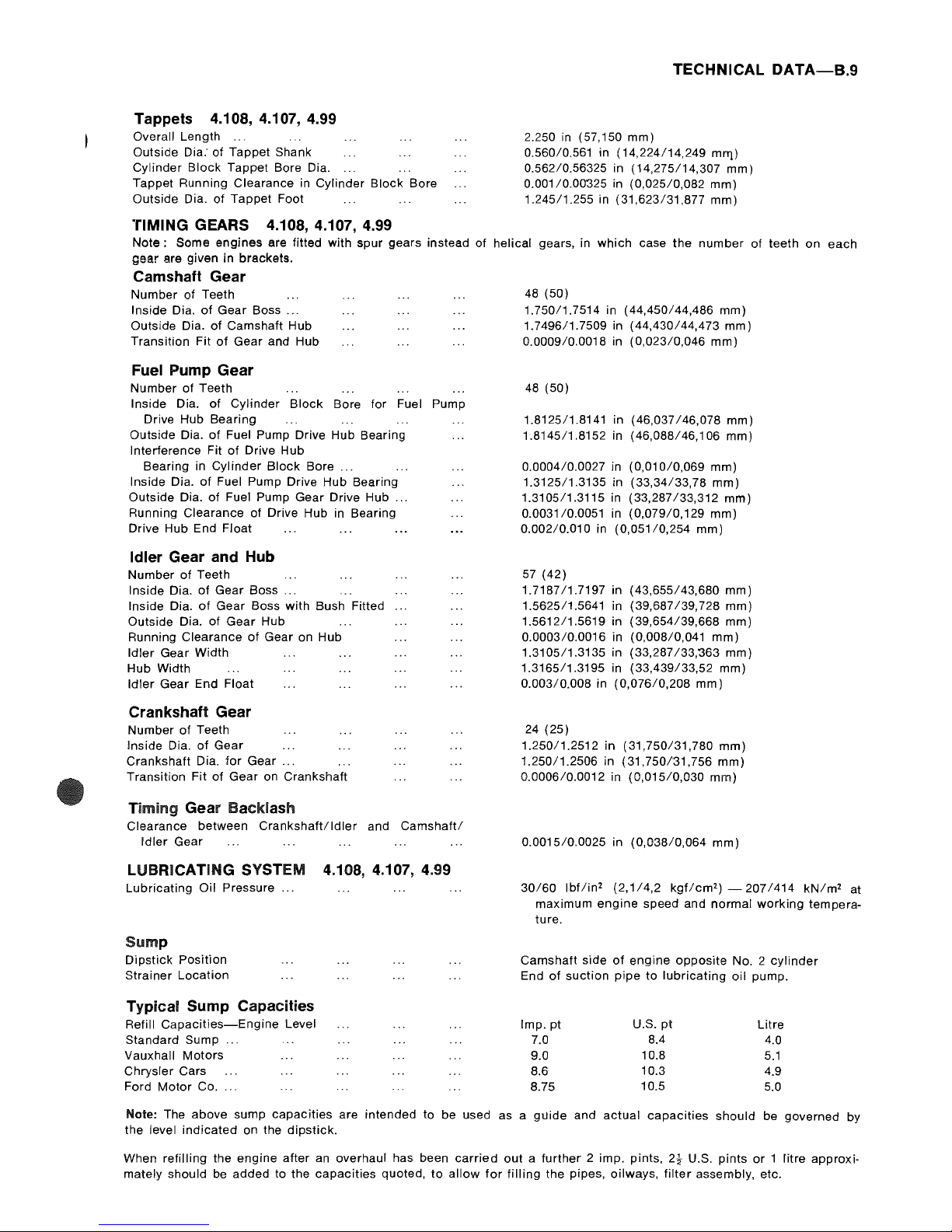
Tappets 4.108, 4.107, 4.99
Overall Length
Outside Dia: of
Tappet
Shank
Cylinder
Block
Tappet Bore Dia.
Tappet Running Clearance in Cylinder
Block
Bore
Outside Dia. of
Tappet
Foot
TIMING GEARS 4.108, 4.107, 4.99
TECHNICAL
DATA-B.9
2.250
in
(57,150
mm)
0.560/0.561 in
(14,224/14,249
mll'l)
0.56210.56325 in
(14,275/14,307
mm)
0.001/0.00"325 in
(0,025/0,082
mm)
1.245/1.255
in
(31,623/31,877
mm)
Note:
Some
engines
are fitted with spur gears instead of helical gears, in
which
case the
number
of teeth
on
each
gear
are given
in
brackets.
Camshaft Gear
Number
of Teeth
Inside Dia.
of
Gear
Boss
...
Outside Dia. of Camshaft Hub
Transition
Fit
of
Gear and Hub
Fuel Pump Gear
Number
of Teeth
Inside Dia.
of
Cylinder
Block
Bore for Fuel Pump
Drive Hub Bearing
Outside Dia.
of
Fuel Pump Drive Hub Bearing
Interference Fit
of
Drive Hub
Bearing in
Cylinder
Block
Bore
...
Inside Dia.
of
Fuel Pump Drive Hub Bearing
Outside Dia.
of
Fuel Pump Gear Drive Hub
...
Running Clearance
of
Drive Hub in Bearing
Drive Hub End
Float
Idler Gear and Hub
Number
of
Teeth
Inside Dia.
of
Gear
Boss
...
Inside Dia.
of
Gear
Boss with Bush Fitted ...
Outside Dia. of
Gear
Hub
Running Clearance
of
Gear on Hub
Idler
Gear Width
Hub Width
Idler
Gear End Float
Crankshaft Gear
Number
of
Teeth
Inside Dia.
of
Gear
Crankshaft Dia.
for
Gear
...
Transition Fit of
Gear
on Crankshaft
Timing Gear Backlash
Clearance between
Crankshaft!ldler
and
Camshaft!
Idler
Gear
LUBRICATING SYSTEM
4.108,4.107,4.99
48
(50)
1.750/1.7514 in
(44,450/44,486
mm)
1.7496/1.7509 in
(44,430/44,473
mm)
0.000910.0018 in
(0,023/0,046
mm)
48
(50)
1.8125/1.8141 in
(46,037/46,078
mm)
1.814511.8152 in
(46,088/46,106
mm)
0.0004/0.0027 in
(0,010/0,069
mm)
1.3125/1.3135
in
(33,34/33,78
mm)
1.3105/1.3115 in
(33,287/33,312
mm)
0.0031/0.0051 in
(0,079/0,129
mm)
0.00210.010 in
(0,051/0,254
mm)
57
(42)
1.7187/1.7197
in
(43,655/43,680
mm)
1.562511.5641 in (39,687139,728
mm)
1.5612/1.5619
in
(39,654/39,668
mm)
0.0003/0.0016
in (0,008/0,041
mm)
1.3105/1.3135
in
(33,287/33,363
mm)
1.316511.3195 in
(33,439/33,52
mm)
0.00310.008 in
(0,076/0,208
mm)
24
(25)
1.25011.2512 in
(31,750/31,780
mm)
1.250/1.2506
in
(31,750/31,756
mm)
0.000610.0012 in
(0,015/0,030
mm)
0.0015/0.0025
in
(0,038/0,064
mm)
Lubricating Oil Pressure
...
30/60
Ibflin
2
(2,1/4,2
kgflcm2)
-2071414
kN/m
2
at
Sump
Dipstick
Position
Strainer Location
Typical Sump Capacities
Refill
Capacities-Engine
Level
Standard Sump
...
Vauxhall
Motors
Chrysler Cars
Ford
Motor
Co
....
maximum
engine
speed and normal
working
tempera-
ture.
Camshaft side
of
engine
opposite
No.2
cylinder
End
of
suction
pipe
to
lubricating
oil pump.
Imp.
pt
U.S.
pt
Litre
7.0
8.4
4.0
9.0
10.8
5.1
8.6
10.3
4.9
8.75
10.5
5.0
Note: The above sump
capacities
are intended
to
be used as a gUide and
actual
capaCities should be governed by
the level
indicated
on the
dipstick.
When refilling the engine
after
an overhaul has been
carried
out a further
2 imp. pints,
2!
U.S.
pints
or 1 litre
approxi-
mately should be added
to
the
capacities
quoted,
to
allow
for
filling
the pipes, oilways,
filter
assembly, etc.
Page 20
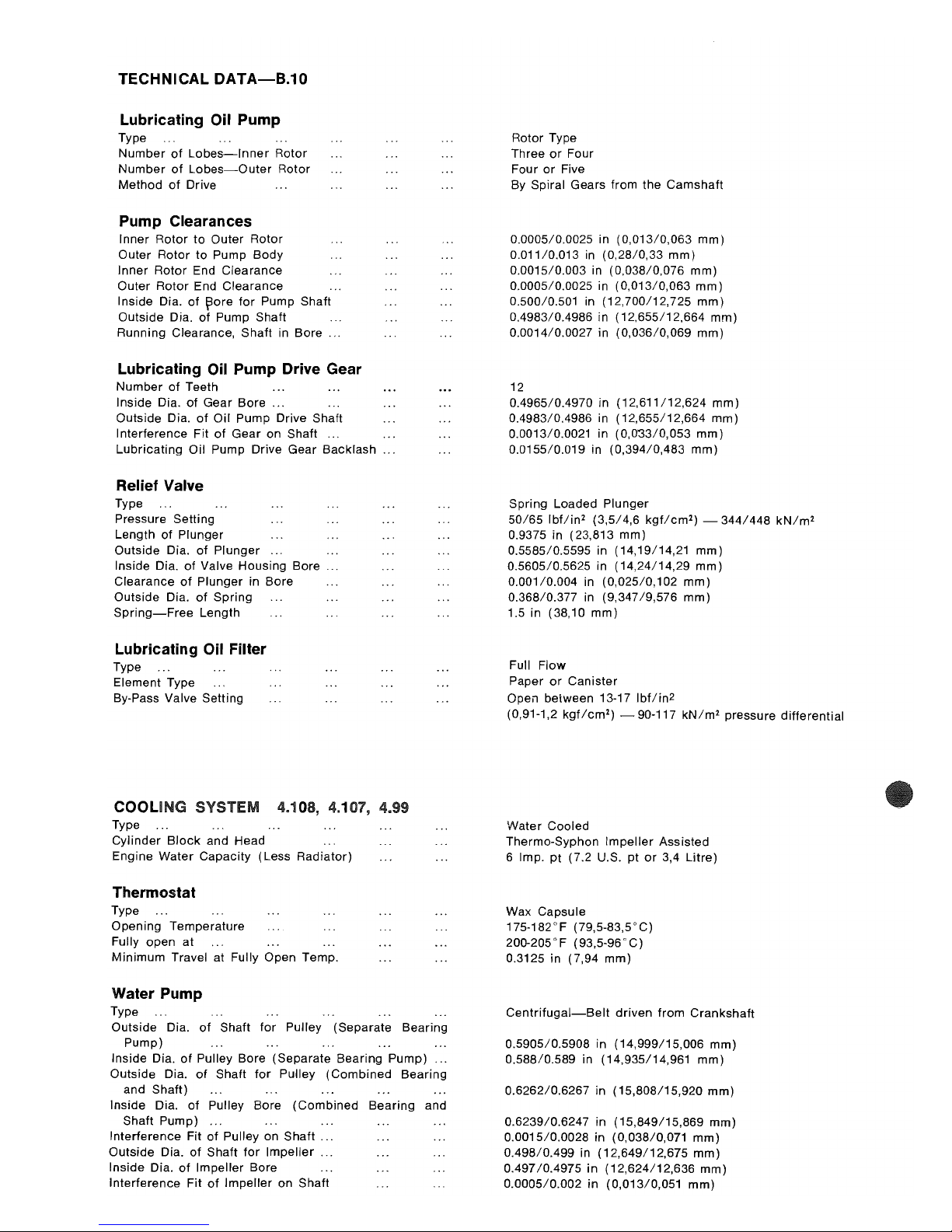
TECHNICAL
DATA-B.10
Lubricating Oil Pump
Type
Number
of
Lobes-Inner
Rotor
Number
of
Lobes-Outer
Rotor
Method
of
Drive
Pump Clearances
Inner
Rotor
to
Outer Rotor
Outer Rotor
to
Pump Body
Inner Rotor End Clearance
Outer
Rotor End Clearance
Inside Dia.
of
~ore
for
Pump Shaft
Outside Dia.
of
Pump Shaft
Running Clearance, Shaft in Bore ...
Lubricating Oil Pump Drive Gear
Number
of
Teeth
Inside Dia. of Gear
Bore
...
Outside Dia.
of
Oil Pump Drive Shaft
Interference Fit of Gear on Shaft ...
Lubricating Oil Pump Drive Gear Backlash
...
Relief Valve
Type
Pressure Setting
Length
of
Plunger
Outside Dia.
of
Plunger
...
Inside Dia.
of
Valve Housing Bore ...
Clearance
of
Plunger in Bore
Outside Dia.
of
Spring
Spring-Free
Length
Lubricating Oil Filter
Type
Element Type
By-Pass Valve Setting
COOLING SYSTEM 4.108, 4.101, 4.99
Type
Cylinder
Block
and Head
Engine Water Capacity (Less Radiator)
Thermostat
Type
Opening Temperature
Fully open
at
Minimum
Travel
at
Fully Open Temp.
Water Pump
Type
Outside Dia.
of
Shaft
for
Pulley (Separate Bearing
Pump)
Inside Dia.
of
Pulley Bore (Separate Bearing Pump)
Outside Dia.
of
Shaft
for
Pulley
(Combined
Bearing
and
Shaft)
Inside Dia.
of
Pulley Bore
(Combined
Bearing
and
Shaft Pump)
...
Interference Fit
of
Pulley on
Shaft
.. .
Outside Dia. of Shaft
for
Impeller
.. .
Inside Dia.
of
Impeller Bore
Interference Fit
of
Impeller on Shaft
Rotor Type
Three
or
Four
Four
or
Five
By
Spiral Gears from the
Camshaft
0.0005/0.0025 in
(0,013/0,063
mm)
0.01110.013 in
(0,28/0,33
mm)
0.0015/0.003 in
(0,038/0,076
mm)
0.0005/0.0025 in
(0,013/0,063
mm)
0.50010.501 in
(12,700/12,725
mm)
0.4983/0.4986 in
(12,655/12,664
mm)
0.0014/0.0027 in
(0,036/0,069
mm)
12
0.496510.4970 in
(12,611/12,624
mm)
0.4983/0.4986 in
(12,655/12,664
mm)
0.001310.0021 in
(0,033/0,053
mm)
0.0155/0.019
in
(0,394/0,483
mm)
Spring Loaded Plunger
50/65
Ibflin2 (3,5/4,6
kgflcm2) -344/448
kN/m
2
0.9375 in (23,813
mm)
0.5585/0.5595 in (14,19/14,21
mm)
0.5605/0.5625 in (14,24/14,29
mm)
0.001/0.004 in (0,025/0,102
mm)
0.368/0.377 in (9,347/9,576
mm)
1.5 in (38,10
mm)
Full Flow
Paper
or
Canister
Open between 13-17
Ibflin
2
(0,91-1,2
kgflcm2)
90-117
kN/m
2
pressure
differential
Water Cooled
Thermo-Syphon
Impeller
Assisted
6 Imp.
pt
(7.2 U.S.
pt
or
3,4
Litre)
Wax Capsule
175-182°F (79,5-83,5°C)
200-205°F (93,5-96°C)
0.3125 in (7,94
mm)
Centrifugal-Belt
driven
from
Crankshaft
0.5905/0.5908 in (14,999/15,006
mm)
0.588/0.589 in (14,935/14,961
mm)
0.6262/0.6267 in (15,808/15,920
mm)
0.6239/0.6247 in (15,849/15,869
mm)
0.0015/0.0028 in (0,038/0,071
mm)
0.498/0.499 in (12,649/12,675
mm)
0.497/0.4975
in (12,624/12,636
mm)
0.0005/0.002 in (0,013/0,051
mm)
Page 21
Outside
Dia. of
Impeller
Water
Pump Seal Type
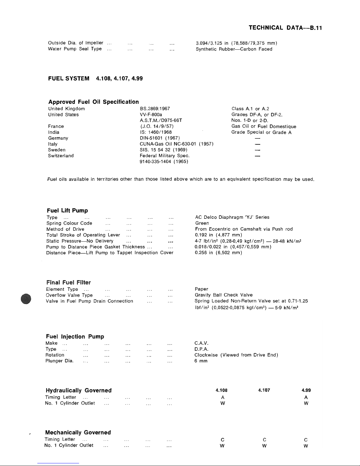
FUEL SYSTEM 4.108,4.107,4.99
Approved Fuel Oil Specification
United Kingdom 8S.2869:1967
United States VV-F-800a
AS.T.M.lD975-66T
France
(J.O.
14/9/57)
India
IS: 1460/1968
Germany DIN-51601 (1967)
TECHNICAL
DATA-B.11
3.094/3.125 in (78,588179,375
mm)
Synthetic
Rubber-Carbon
Faced
Class
A1
or
A2
Grades OF-A,
or
DF-2.
Nos.
1-0
or
2-D.
Gas Oil
or
Fuel Domestique
Grade
Special
or
Grade A
Italy CUNA-Gas Oil NC-630-01 (1957)
Sweden SIS.
155432
(1969)
Switzerland Federal
Military
Spec.
9140-335-1404 (1965)
Fuel
oils
available in territories
other
than those listed
above
which are to an
equivalent
specification
may be used.
Fuel Lift Pump
Type
Spring
Colour
Code
Method
of
Drive
Total Stroke
of
Operating Lever
Static
Pressure-No
Delivery
Pump to Distance Piece Gasket Thickness
...
Distance
Piece-Lift
Pump
to
Tappet Inspection Cover
Final Fuel Filter
Element Type
Overflow Valve Type
Valve in Fuel Pump Drain Connection
Fuel Injection Pump
Make
Type
Rotation
Plunger Dia.
Hydraulically Governed
Timing Letter
No. 1
Cylinder
Outlet
Mechanically Governed
Timing Letter
No. 1
Cylinder
Outlet
AC
Delco
Diaphragm 'Y J' Series
Green
From
Eccentric
on Camshaft via Push rod
0.192 in (4,877
mm)
4-7
Ibflin
2
(0,28-0,49
kgflcm2)
- 28-48
kN/m
2
0.018/0.022 in (0,457/0,559
mm)
0.256 in (6,502
mm)
Paper
Gravity
8all
Check
Valve
Spring Loaded Non-Return Valve set
at
0.71-1.25
Ibflin
2
(0,0522-0,0875
kgflcm2)
- 5-9
kN/m
2
CAV.
D.P.A.
Clockwise
(Viewed
from Drive End)
6 mm
4.108
A
W
C
W
4.107
c
W
4.99
A
W
C
W
Page 22
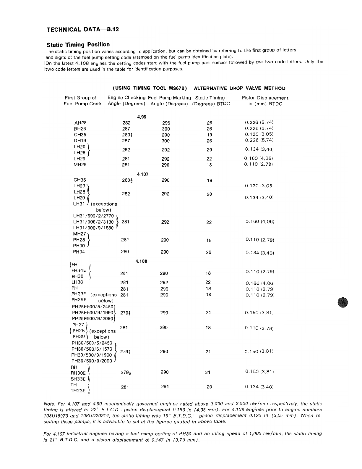
TECHNICAL
DATA-B.12
Static Timing Position
The static timing position varies according
to
application, but can
be
obtained by referring
to
the first group
of
letters
and digits
of
the
fuel pump setting code (stamped on the fuel pump identification plate).
IOn the latest
4.108
engines the setting codes start
with
the fuel pump part number followed by
the
two
code letters. Only
the
Itwo
code letters are used
in
the table for identification purposes.
(USING TIMING TOOL MS67B)
ALTERNATIVE DROP VALVE METHOD
First
Group
of
Engine
Checking
Fuel Pump
Marking
Static
Timing
Piston
Displacement
Fuel
Pump
Code
Angle
(Degrees)
Angle
(Degrees)
(Degrees)
BTDC
in
(mm)
BTDC
4.99
AH28
282
29S
26
0.226
(5,74)
BH26
287
300
26
0.226
(5,74)
CH3S
280~
290 19
0.120
(3,05)
DH19
287
300
26
0.226
(5,74)
LH20 }
282
292
20
0.134
(3,40)
LH26
LH29
281
292
22
0.160
(4,06)
MH26
281
290
18
0.110
(2,79)
4.107
CH3S
280~
290
19
LH23}
0.120
(3,05)
LH28
282
292
20
LH29
0.134
(3,40)
LH31
(exceptions
below)
LH31
1900/2/2770
}
LH31
1900/2/3130
281
292
22
0.160
(4,06)
LH31
1900/9/1880
MH27}
PH28
281
290
18
0.110
(2,79)
PH30
PH34
280
290
20
0.134
(3,40)
iEH
4.108
EH34E
281
290
18
0.11
°
(2,79)
EH39
LH30
281
292
22
0.160
(4,06)
IpH
281
290 18
0.1 0
(2,79)
PH23E
(exceptions
281
290 18
0.110
(2,79)
PH25E
below)
PH2SESOO/S/24S0}
PH2SESOO/9/1990
279~
290
21
0.150
(3,81)
PH2SESOO/9/2090
PH27
~
-
281
290
18
'0.110
(2,79)
i PH28
(exceptions
PH30 be/ow)
PH30/S00/5/24SO }
PH30/S00/6/1S70
279t
290
21
0.150
(3,81)
PH30/S00/9/1990
PH30/S00/9/2090
:RH
1
RH30E
279~
290
21
0.150
(3,81)
SH33E
ITH }
281
291
20
0.134
(3,40)
ITH23E .
Note:
For 4.107
and
4.99
mechanically
governed
engines r aled
above 3,000
and
2,SOO
rev I
min
respectively, the
static
timing
is
altered
to
22'
B.T.C.D.'
piston
displacement
0.160 in
(4,06
mmJ.
For
4.108
engines
prior
to
engine
numbers
108U15973
and
108UD20214, the
static
timing
was
19'
B.T.D.C.·,
piston
displacement
0.120 in (3,05
mm).
When re,
setting
these pumps,
it
is
advisable
to
set
at
the figures
quoted
in
above
table.
For 4.107
industrial
engines
having
a fuel
pump
coding
of
PH30
and
an
idling
speed
at
1,000
rev/min,
the
static
timing
is
21'
B.T.D.C.
and a piston
displacement
of
0.147 in
(3,73
mm).
Page 23
I
I
I
",-(I!I'"
I
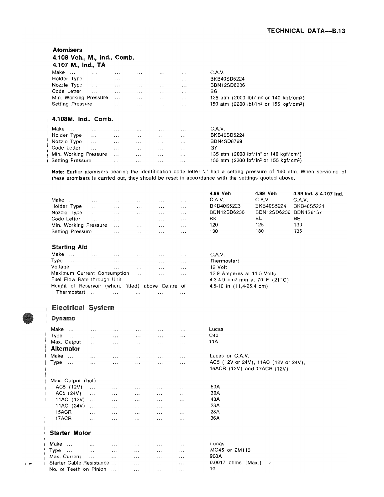
Atomisers
4.108 Veh., M., Ind., Comb.
4.107 M., Ind.,
TA
Make
...
Holder
Type
Nozzle Type
Code Letter
Min.
Working
Pressure
Setting Pressure
4.108M, Ind., Comb.
Make
...
Holder
Type
Nozzle Type
Code Letter
! Min. Working Pressure
I Setting Pressure
CAV.
BKB40S05224
BON 12S06236
BG
TECHNICAL
DATA-B.13
135 atm (2000
Ibflin2
or
140
kgf/cm2)
150 atm (2200
Ibf/in2
or
155 k9f1cm2)
CAV.
BKB40S05224
BDN4SD6769
GY
135 atm (2000
Ibflin2 or
140
kgflcm2)
150 atm (2200
Ibflin2 or
155
kgflcm2)
Note: Earlier atomisers bearing the identification code
letter
'J' had a setting pressure
of
140 atm. When
servicing
of
these atomisers is
carried
out, they should be reset in
accordance
with the settings quoted above.
Make
Holder
Type
Nozzle Type
Code Letter
Min. Working Pressure
Setting Pressure
Starting Aid
Make
Type
Voltage
Maximum Current Consumption
Fuel Flow Rate
through
Unit
Height of Reservoir (where fitted) above Centre of
Thermostart
...
Make ...
Type
...
Max. Output
Alternator
Make
Type
...
Max. Output
(hot)
AC5 (12V)
AC5 (24V)
11AC (12V)
..
11AC (24V)
15ACR
17ACR
Starter
Motor
Make
...
Type
...
Max.
Current
Starter Cable Resistance ...
No. of Teeth on Pinion
...
4.99 Veh 4.99
Veh
4.99 Ind. & 4.107 Ind.
CAV. CAV.
CAV.
BKB40S5223 BKB40S5224
BKB40S5224
BON12SD6236 BDN12SD6236 BDN4S6157
BK
120
130
CAV.
Thermostart
12
Volt
BL
125
130
12.9 Amperes
at
11.5 Volts
4.3-4.9 cm
3
min
at
70"F
(21'C)
4.5-10 in (11,4-25,4
cm)
Lucas
C40
11A
Lucas
or
C.A.V.
BE
130
135
AC5
(12Vor24V),
11AC
(12Vor24Vj,
15ACR (12V) and 17ACR
(12V)
53A
30A
43A
23A
28A
36A
Lucas
MG45
or
2M113
900A
0.0017
ohms
(Max.)
10
Page 24

Page 25
SECTION C
Operating and Maintenance
Starting the Engine
If
the
weather
is warm
or
the engine has only been
stopped
for a little
while, place the
accelerator
in the
fully open
position
and engage the
starter
motor
by
turning the
starter
switch
in a
clockwise
direction
to
the
"HS"
position
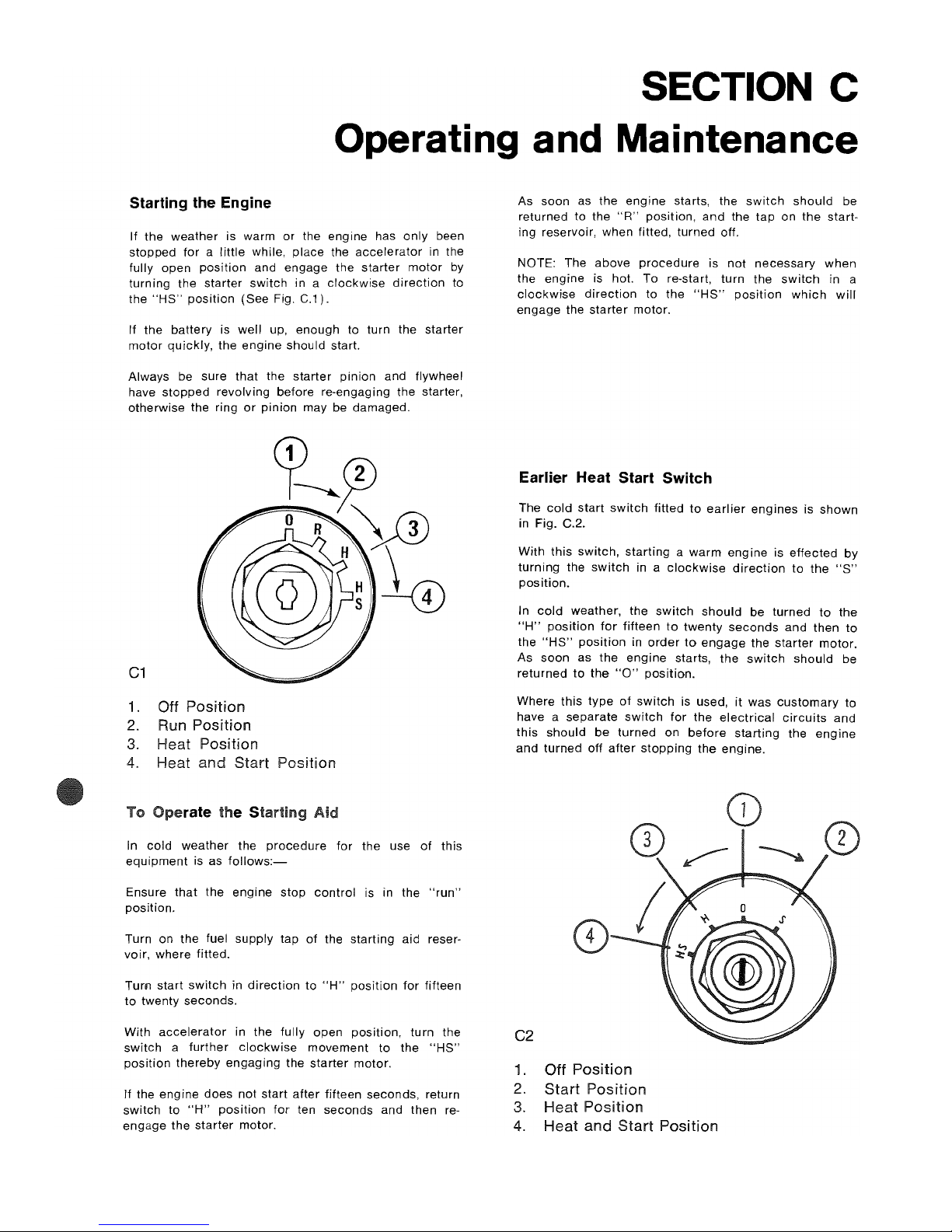
(See Fig. C.1).
If
the
battery
is
well
up, enough to turn the
starter
motor
quickly,
the
engine
should start.
Always be sure
that
the
starter
pinion
and flywheel
have
stopped
revolving before re-engaging the starter,
otherwise
the
ring
or
pinion
may be damaged.
C1
1.
Off Position
2.
Run Position
3.
Heat Position
4.
Heat and Start Position
To
Aid
In
cold
weather
the
procedure
for
the use
of
this
equipment
is as
follows:-
Ensure
that
the
engine
stop
control
is in the
"run"
position.
Turn on the fuel supply
tap
of
the starting aid reser-
voir, where fitted.
Tum
start
switch
in
direction
to
"H"
position
for
fifteen
to
twenty
seconds.
As soon as the engine starts, the
switch
should
be
returned to the
"R"
position,
and
the
tap
on
the
start-
ing reservoir, when fitted,
turned
off.
NOTE: The above
procedure
is
not
necessary
when
the
engine
is hot.
To
re-start,
turn
the
switch
in a
clockwise
direction
to the
"HS"
position
which
will
engage
the
starter
motor.
Earlier Heat Start Switch
The
cold
start
switch
fitted
to
earlier
engines
is
shown
in Fig. C.2.
With this
switch,
starting a warm
engine
is
effected
by
turning
the
switch
in a
clockwise
direction
to
the
"S"
position.
In
cold
weather, the
switch
should
be
turned
to
the
"H"
position
for
fifteen
to
twenty
seconds
and
then
to
the
"HS"
position
in
order
to
engage
the
starter
motor.
As
soon
as the
engine
starts,
the
switch
should
be
returned
to
the
"0"
position.
Where
this
type
of
switch
is used,
it
was
customary
to
have a
separate
switch
for
the
electrical
circuits
and
this
should
be
turned
on
before
starting
the
engine
and
turned
off
after
stopping
the
engine.
With
accelerator
in the fully
open
position,
turn
the C2
switch a further
clockwise
movement
to
the
"HS"
position
thereby
engaging
the
starter
motor.
If the engine
does
not start
after
fifteen seconds, return
switch
to
"H"
position
for
ten
seconds
and
then re-
engage
the
starter
motor.
1.
Off Position
2.
Start Position
3.
Heat Position
4.
Heat and
Start
Position
Page 26
OPERATING AND
MAINTENANCE-C.2
Alternative Method
With some engines, a different starter switch is pro-
vided
and the cold
start
aid is operated by means
of
a
separate push button switch.
The
cold
starting
procedure
is the same i.e.
Switch
on by turning the starter switch in a
clockwise
direction
to the first position.
Press the heater button for fifteen
to
twenty seconds
and then,
with
the
heater
button still pressed, turn the
starter
switch
in a
further
clockwise
direction
to engage
the
starter
motor. As
soon
as the engine starts, release
switch
and heater button.
I Glow Plugs
Glow
plugs are sometimes fitted to engines in applica-
tions
such as refrigeration units, fork
lift
trucks
and
other
certain 4.108
mechanically
governed engines
rated at 3,000
rev/min
and below. As the buss bar
connecting
these
glow
plugs may not be insulated,
extreme care must be exercised to keep pipes, clips
or
other
metal
objects
well clear
as
the consequences
of a
direct
short of this buss
bar
to
earth when
energised are obvious.
It must be noted
that
in
no
circumstances
should
either
or
any other unauthorised starting aids be used
at the same time as
glow
plugs.
To operate, use the
following
procedure
:-
Before operating the starter motor, press the
"Heat"
button for
20
to
30
seconds.
I With the
"Heat"
button still pressed, engage the
I starter
motor
until the
engine
starts.
I Continue
to
press the
"Heat"
button
for
a few seconds
I after the engine has started until even running has
: been obtained.
Ilf
the engine does not start, disengage the starter
I motor,
but
keep the
"Heat"
button pressed
for
a
I
further
10
to
15 seconds, when a
further
attempt should
I be made
to
start the engine, keeping the
glow
plugs
I energised whilst starting and for a few seconds after
ithe
engine
has fired until even running is obtained.
Points
to
Note
Ensure
that
the
electrical
connection
to the starting aid
is
correctly
made.
Always ensure
that
the reservoir feeding fuel
to
the
starting aid is fully primed and is not leaking. With
some
later
engines, this fuel
reservoir
has been deleted,
the
cold
start
aid being fed
direct
from the fuel filter
through
a non-return valve.
Extended use
of
the
cold
starting
equipment
above the
time
periods already stated should be avoided, other-
wise the starting aid in the
induction
manifold
may be
damaged also continuous flaming
will
starve the
engine
of oxygen.
In the event
of
difficult
starting,
check
that
fuel is
reaching the starting aid in the
induction
manifold
by
unscrewing
the
inlet
fuel
connection.
If fuel is reaching
it
satisfactorily, then
it
may be that the
starting
aid it-
self
is not
working
correctly. This can be
checked
by
removing the
air
cleaner
and
watching
the starting
aid
whilst
the
equipment
is used. When the
starting
switch
is turned
to
the
"heat"
position,
the
element
should
become red hot, and upon
engagement
of
the
starter
motor
ignition
of
the fuel
should
take
place.
4.108, 4.107 and 4.99 engines are
fitted
with
efficient
starting
equipment
and
no
responsibility
can be
accepted
for
any damage caused
by
unauthorised
start-
ing aids.
To prevent thermostart damage,
it
is
essential
that
the
thermostart is not operated DRY.
After
any
operation
which allows fuel to drain from
the the
thermostart
feed
pipe, the pipe must be
disconnected
at
the
thermostart
and all air bled from the pipe before the
thermostart
is
operated.
Where a
thermostart
starting aid has to be replaced,
care must be taken
not
to
exceed
the
torque
figure
quoted on Page B.2. Excessive
torque
loading
can
crack
the
insulator
adaptor
causing an
electrical
short
and
hard starting characteristics.
Stopping the Engine
A spring
loaded
stop
control
is
located
near
the
normal
engine
controls
and
functions
by
cutting
off
the fuel
at
the fuel
injection
pump.
To
operate, pull the
knob
and
hold
in
mis
position
until
the engine ceases
to
rotate. Ensure
that
the
control
returns to the
"run"
position,
otherwise
difficutly
may
be
experienced
in re-starting the engine.
Return latest
cold
start
switch
to
the
"0"
position.
Some
engines
may have an
electric
solenoid
stop
control on the fuel
injection
pump
operated
by a switch
on the
control
panel.
Running In Procedure
It is not necessary
to
gradually
run-in a
new
or
factory
rebuilt
engine
and any
prolonged
light
load running
during the early life of the
engine
can in
fact
prove
harmful
to
the
bedding in of piston rings and liners.
Full load can be applied
On
a new
or
factory
rebuilt
engine as soon as the
engine
is used,
provided
that
the
engine
is
first
allowed to reach a
temperature
of
at
least
140°F
(60°C).
PREVENTIVE MAINTENANCE
I These preventive
maintenance
periods
are general in
I
application.
Check
the
periods
given by the manu-
I
facturer
of the
equipment
in
which
the engine is
1 installed and,
where
necessary, use the
shorter
periods.
I These
periods
and
procedures
must also be adapted
I
to
ensure
correct
operation
for
any local machine
I regulations.
I It is good
maintenance
to
check
for
leakage and loose
I fasteners at each service interval.
I 1 hese
maintenance
periods
are
only
for
engines that
I are
operated
with fuel and
lubricating
oil to the
I
specifications
given in
this
manual.
I The
schedules
which
follow
must be applied at the
I interval
(miles,
kilometres, hours
or
months)
which
I
occurs
first.
Page 27
I On
stop
start
low
mileage
work,
the
hours
run are
more
applicable
than
the
mileage
covered.
Daily or every 8 hours
Check
coolant
level.
Check
sump oil level.
Check
oil pressure
(where
gauge is
fitted).
In extreme dust conditions, clean oil bath
air
cleaner
and empty dust
bowl
on dry type
air
cleaner.
Every 4,000 miles (6,000 km),
150 hours or 3 months
t Drain and renew
lubricating
oil (see list of approved
lubricating
oils
Appendix).
t Renew lubricating
oil
filter
element
or
canister.
Clean oil bath
air
cleaner.
Empty dust bowl on
dry
type
air
cleaner.
'Check
drive
belt tension.
Clean
water
trap.
Lubricate
dynamo
rear
bush (where
applicable).
Every 12,000 miles (18,000 km)
450 hours or 12 months
t Renew final fuel
filter
element -
agricultural
and in-
dustrial
applications.
Clean element
of
dry
type
air
cleaner
or
renew
(if
not
indicated
earlier).
Every 24,000 miles (36,000
km)
or 900 hours
Renew final fuel
filter
element -vehicle
applications.
miles (108,000
or
hours
Arrange
for
examination
and service
of
proprietary
equipment, i.e., compressor, exhauster, starter,
dynamo
etc.
Service atomisers.
Check
and
adjust
valve clearance.
t I
Refrigeration
unit
engines
have a larger
capacity
I
sump
and
larger
lubricating
oil
filter
canister,
therefore
the
lubricating
oil
and
filter
change
can
be
extended
to
1000
hours.
Also
with a primary
fuel
oil
filter
fitted,
the
main
fuel
filter
element
change
period
can
be
extended
to
1000
hours.
'The
drive belt
tension
should be
checked
monthly
on
engines rated
above
3,000
rev/min.
POST DELIVERY CHECKOVER
After a customer
has taken
delivery
of his Perkins
Diesel engine, it is advisable,
in
his own interest, that
a general
checkover
of
the engine be
carried
out
after
4.108
Series Workshop Manual, June
1986
OPERATING AND
MAINTENANCE-C.3
the first 500/1000 miles
(800/1600
km)
or
25/50
hours
in service.
It is also recommended
that
the
following
procedure
be adopted where an
engine
has been
laid
up
for
a
considerable period before it is again
put
into
service.
With the engine
thoroughly
warmed
through,
this
checkover
should
comprise
the
following
points.
1.
Drain
lubricating
oil sump. Renew
lubricating
oil
filter
element
or
canister.
(Refer
to
Page L.5
or
L.6)
.
2.
Remove the
rocker
assembly,
check
that
the
cylinder
head nuts are
to
the
correct
torque.
(Refer
to Page
B.2).
3.
Refit
rocker
assembly and set valve
clearances.
(Refer to Page
B.8).
4.
Refill
lubricating
oil sump
with
clean
new
oil
to
the
correct
level.
(Do
not
overfill).
5.
Check fan belt tension.
(Refer
to Page
M.1).
6.
Check
coolant
level in radiator,
inspect
for
any
coolant
leaks.
7.
Check
security of all external nuts, setscrews,
hose
clips, mountings, etc.
8.
Start engine and
check
for
any fuel
or
lubricating
oil leaks.
9.
Carry
out
test to
check
general
performance
of
engine.
Thereafter routine
maintenance
should be in
accord-
ance with Periodical Attentions
which
are given on
previous Page.
NOTE: If the
cylinder
head
is
removed
for
any
reason
e.g. top overhaul, then
it
is
recommended
that
the
cylinder
head
nuts are
retorqued
as
shown
in Fig. E.23
after
500/1000
miles
(800/1600
km)
or
25/50
hours
with the engine hot, to the
setting
given on Page B.2.
It
is
assumed
that
electrical
equipment
will
have
already
been
checked
for
such
points
as
dynamo
rate
of
charge, effectiveness
of
connections
and
circuits,
etc.
ProtecUon
of
an engine
not
in
service
The
recommendations
given
below
are
to
ensure
that
damage
is prevented when an
engine
is removed from
service
for
an
extended period. Use these
procedures
immediately
the
engine
is removed from service. The
instructions
for
the
use
of
POWERPART
products
are
given on the
outside
of
each
container.
1.
Thoroughly
clean
the
outside
of
the
engine.
2.
Where a preservative fuel is
to
be
used,
drain
the
fuel system and fill
with
the
preservative fuel.
POWERPART
lay-Up
1 can
be
added
to
the
normal
fuel
to
change
it
to
a preservative fuel. If
preservative fuel
is
not
used, the system can
be
Kept charged
with
normal fuel
but
this
will have
to
be
drained
and
discharged
at
the end of the
period
together
with
the fuel filter.
3.
Run the
engine
until
it
is warm.
Correct
any fuel,
lubricating
oil
or
air
leakage. Stop the
engine
and
drain
the
lubricating
oil
sump.
4.
Renew the
lubricating
oil filter canister.
5.
Fill
the
sump
to
the
tull
mark
on the
dipstick
with
c,ean
new
lubricating
oil
or
with a correct
preservative fluid. POWERPART
lay-Up
2 can be
added
to
the
lubricating
oil
to
give protection
against
corrosion
curing
the
period
in storage.
If a preservative fluid is used, this must be
drained
and
normal
lubricating
oil used when the
engine
is
returned
to service.
Page 28
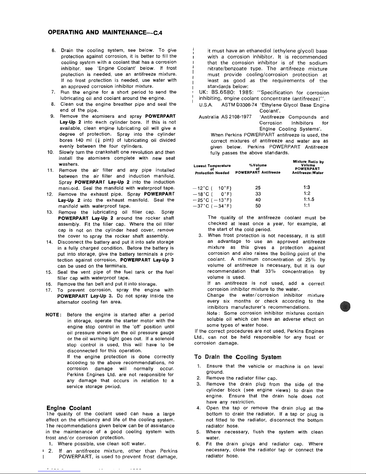
OPERATING
AND
MAINTENANCE-C.4
6.
Drain the
cooling
system, see below. To give
protection against corrosion, it
is
better to fill the
cooling system with a coolant that has a corrosion
inhibitor, see 'Engine Coolant' below.
If frost
protection is needed, use
an
antifreeze mixture.
If no frost protection is needed, use water with
an
approved corrosion inhibitor mixture.
7.
Run the engine
for
a short period
to
send the
lubricating oil and coolant around the engine.
8.
Clean out the engine breather pipe and seal the
end of the pipe.
9.
Remove the atomisers and spray POWERPART
Lay-Up 2 into each cylinder bore. If this is not
available, clean engine lubricating oil will give a
degree of protection. Spray into the cylinder
bores 140 ml
L1-
pint)
of lubricating oil divided
evenly between the
four
cylinders.
10. Slowly turn the crankshaft one revolution and then
install the atomisers complete with
new
seat
washers.
11. Remove the air filter and any pipe installed
between the air filter and induction manifold.
Spray
POWERPART Lay-Up 2 into the induction
manioold. Seal the manifold with waterproof tape.
12. Remove the exhaust pipe. Spray
POWERPART
Lay-Up 2
into the exhaust manifold. Seal the
manifold with waterproof tape.
13. Remove the lubricating oil
filler
cap. Spray
POWERPART Lay-Up 2 around tne
rocker
shaft
assembly. Fit the filler cap. Where the oil filler
cap is not on the cylinder head cover, remove
the cover to spray the rocker shaft assembly.
14. Disconnect the battery and put
it
into safe storage
in a fully charged condition. Before the battery is
put into storage, give the battery terminals a pro-
tection against corrosion.
POWERPART Lay-Up 3
can be used on the terminals.
15. Seal the vent pipe of the fuel tank
or
the fuel
filler
cap with waterproof tape.
16. Remove the fan belt and
put
it
into storage.
17. To prevent corrosion, spray the engine with
POWERPART Lay-Up 3. Do not spray inside the
alternator cooling fan area.
NOTE:
Before the engine is started after a period
in storage, operate the starter
motor
with the
engine stop control in the 'off' position until
oil pressure shows on the oil pressure gauge
or
the oil warning
light
goes out. If a solenoid
stop control is used, this will have
to
be
disconnected
for
this operation.
If the engine protection is done correctly
accoding
to
the above recommendations, no
corrosion damage will
normally
occur.
Perkins Engines Ltd. are
not
responsible
for
any damage that
occurs
in relation
to
a
service storage period.
Engine Coolant
1 he quality
of
the coolant used can have a large
effect on the efficiency and life
of
the
cooling
system.
The recommendations given
below
can be of assistance
in the maintenance of a good
cooling
system with
frost
and/or
corrosion protection.
1.
Where possible, use clean soft water.
I
2.
If
an
antifreeze
mixture,
other
than
Perkins
POWERPART, is
used
to
prevent
frost
damage,
it
must
have
an
ethanediol
(ethylene
glycol)
base
with a corrosion
inhibitor.
It
is
recommended
that
the
corrosion
inhibitor
is
of
the
sodium
nitrate/benzoate
type.
The
antifreeze
mixture
must
provide
cooling/corrosion
protection
at
least as
good
as
the
requirements
of
the
standards
below:
UK:
8S.6580:
1985:
"Specification
for
corrosion
inhibiting,
engine
coolant
concentrate
(antifreeze)".
U.S.A. ASTM 03306-74 'Ethylene Glycol Base Engine
Coolant'.
Australia
AS 2108-1977 'Antifreeze
Compounds
and
Corrosion
Inhibitors
for
Engine
Cooling
Systems'.
When Perkins POWER PART antifreeze is used, the
correct
mixtures of antifreeze and water are as
given below. Perkins POWERPART Antifreeze
fully passes the above standards.
Lowest
Temperature
of
Protection
Needed
-12°C ( 10°F)
-18°C
( O°F)
25°C (
13°F)
-37°C
(-34°F)
%Volume
of
POWERPART
Antilreeze
25
33
40
50
Mixture
Ratio
by
Volume
POWERPART
Antifreeze:Water
1:3
1:2
1:1.5
1
:1
The quality of the antifreeze coolant must be
checked at least once a year,
for
example, at
the start of the cold period.
3.
When frost protection is
not
necessary, it is still
an
advantage
to
use an approved antifreeze
mixture as
this
gives a protection against
corrosion and also raises
the
boiling
point
of the
coolant. A minimum
concentration
of 25% by
volume of antifreeze is necessary, but
it
is our
recommendation that
33%
concentration by
volume is used.
If an antifreeze is not used, add a
correct
corrosion
inhibitor
mixture
to
the water.
Change the
water/corrosion
inhibitor
mixture
every six
months
or
check
according
to
the
inhibitors manufacturer's recommendations.
Note:
Some corrosion
inhibitor
mixtures contain
soluble oil
which
can have an adverse effect on
some types of water hose.
If the
correct
procedures
are
not
used, Perkins Engines
Ltd., can
not
be held responsible
for
any frost
or
corrosion damage.
To Drain the Cooling System
1.
Ensure that
the
vehicle or machine is on level
ground.
2.
Remove
the
radiator filler cap.
3. Remove
the
drain
plug
from
the side of the
cylinder
block
(see engine views)
to
drain the
engine. Ensure that the drain hole does not
have any restriction.
4.
Open the tap
or
remove the drain plug at the
bottom
to
drain the radiator. If a tap
or
plug is
not fitted
to
the radiator, disconnect the bottom
radiator hose.
5.
Where necessary, flush the system with clean
water.
6. Fit the
drain
plugs and radiator cap. Where
necessary,
close
the radiator tap or connect the
radiator hose.
Page 29
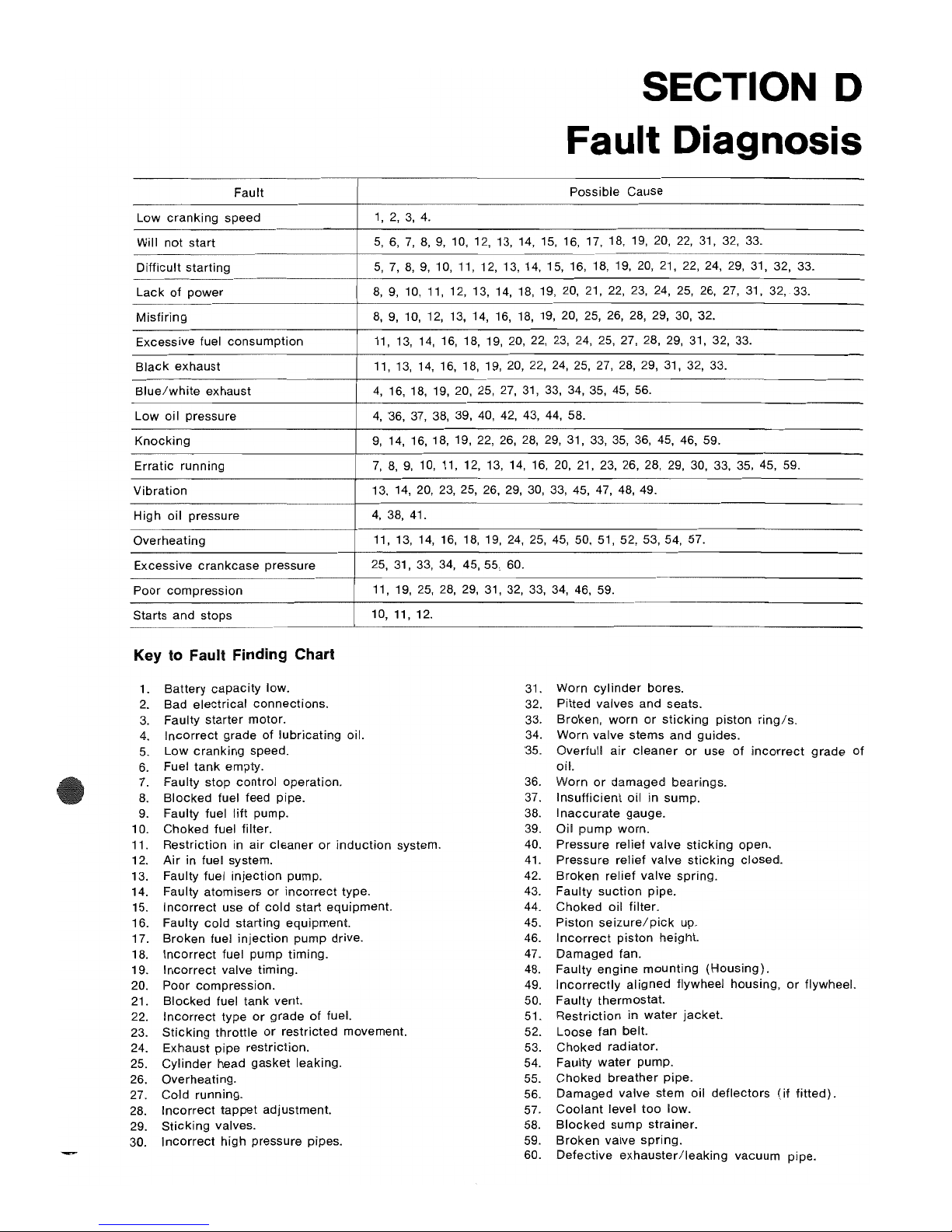
SECTION D
Fault Diagnosis
Fault
Possible Cause
Low
cranking
speed
1,
2,
3,
4.
Will not
start
5,
6,
7,
8,
9,
10, 12,
13, 14, 15,
16,
17, 18, 19,
20,
22,
31, 32,
33.
Difficult starting
5,7,8,9,10,11,12,13,14,15,16,18,19,20,21,22,24,29,
31,
32, 33.
Lack
of
power
8,9,
10, 11,
12, 13,
14,
18,
19,
20, 21,
22, 23, 24,
25, 26,
27,31,
32, 33.
Misfirjng
8,
9,
10,
12,
13, 14, 16,
18, 19,
20, 25,
26,
28, 29,
30,
'32.
Excessive fuel
consumption
11,
13, 14, 16, 18, 19,
20, 22,
23, 24,
25,
27, 28, 29,
31, 32, 33.
Black
exhaust
11,13,14,16,18,
19,20,22,24,25,27,28,29,31,32,33.
Blue/white
exhaust
4,
16, 18, 19, 20, 25,
27,
31,
33, 34, 35,
45,
56.
Low
oil pressure
4,
'36,
37, 38,
39,
40,
42,
43,
44, 58.
Knocking
9,
14, 16, 18, 19, 22,
26,
28,
29,
31,
33,
35, 36,
45,
46, 59.
Erratic
running
7,
8,
9,
10, 11, 12, 13,
14,
16,
20, 21, 23, 26,
28,
29,
30,
33, 35,
45, 59.
Vibration
13, 14,
20,
23,
25,
26,
29,
30,
33,
45, 47,
48,
49.
High oil pressure
4,
38,
41.
Overheating
11,
13, 14, 16,
18,
19,
24,
25,
45,
50, 51, 52, 53,
54,57.
Excessive crankcase pressure
25,
31, 33, 34,
45, 55, 60.
Poor compression
11,19,25,28,29,31,32,33,34,46,59.
Starts and stops
10, 11, 12.
Key
to Fault Finding Chart
1.
Battery
capacity
low.
31. Worn
cylinder
bores.
2.
Bad
electrical
connections.
32.
Pitted
valves and seats.
3. Faulty starter motor.
33. Broken,
worn
or
sticking
piston ring/so
4.
Incorrect
grade
of
lubricating oil.
34.
Worn valve stems
and
guides.
5.
low
cranking
speed.
'35.
Overfull
air
cleaner
or
use
of
incorrect
grade
of
6. Fuel
tank
empty.
oil.
7.
Faulty stop
control
operation.
36. Worn
or
damaged bearings.
8.
Blocked
fuel feed pipe.
37.
Insufficient
oil
in sump.
9.
Faulty fuel
lift
pump.
38.
Inaccurate
gauge.
10. Choked fuel filter.
39.
Oil
pump
worn.
11. Restriction in air
cleaner
or
induction
system.
40. Pressure relief valve
sticking
open.
12.
Air
in fuel system.
41.
Pressure relief valve
sticking
closed.
13. Faulty fuel
injection
pump.
42.
Broken
relief
valve spring.
14. Faulty atomisers
or
incorrect
type.
43. Faulty
suction
pipe.
15.
Incorrect
use
of
cold
start
equipment.
44.
Choked
oil filter.
16. Faulty
cold
starting equipment.
45. Piston
seizure/pick
up.
17. Broken fuel
injection
pump drive.
46.
Incorrect
piston
height.
18.
Incorrect
fuel pump timing.
47.
Damaged
fan.
19.
Incorrect
valve timing. 48. Faulty
engine
mounting
(Housing).
20.
Poor
compression. 49.
Incorrectly
aligned
flywheel housing,
or
flywheel.
21.
Blocked
fuel tank vent. 50. Faulty thermostat.
22.
Incorrect
type
or
grade
of fuel. 51.
Restriction
in
water
jacket.
23.
Sticking
throttle
or
restricted movement.
52.
Loose
fan belt.
24. Exhaust
pipe
restriction. 53.
Choked
radiator.
25.
Cylinder
head
gasket
leaking.
54. Faulty
water
pump.
26. Overheating.
55.
Choked
breather
pipe.
27. Cold running. 56.
Damaged
valve stem oil deflectors
(if
fitted).
28.
Incorrect
tappet
adjustment. 57.
Coolant
level
too
low.
29.
Sticking
valves.
58.
Blocked
sump
strainer.
30.
Incorrect
high pressure pipes. 59.
Broken
valve
spring.
60.
Defective
exhauster/leaking
vacuum pipe.
Page 30

Page 31

E1
Before
commencing
to
overhaul
the
cylinder
head
ensure
that all
joints,
gaskets
and any
other
parts
ex-
pected
to
be
required
are available.
Remove any
external
components
from the
vicinity
of
the
cylinder
head cover,
atomisers
and fuel pump.
E3
SECTION E
Cylinder Head
E2
To Remove the Cylinder
Head
1.
Completely
drain
the
cooling
system.
2.
Disconnect
the
battery
terminals.
3. Remove
the
securing
nuts
and
detach
the
exhaust
pipe
from
the
exhaust
manLold.
Blank
off
the
end
of
the
exhaust
pipe
to
prevent
entry
of
any
foreign
matter.
Page 32

CYLINDER
HEAD-E.2
E4
4.
Uncouple
the
water
outlet
connection
on the
front
of
the
cylinder
head.
5.
Remove
the
air
cleaner
and
place
somewhere
level
ready
for
servicing.
6.
Disconnect
the fuel
pipe
and
electrical
connection
to
the
starting
aid
located
in
the
induction
mani-
fold.
(Refer
to
Fig.
E.1).
E5
E6
7.
Remove
the
cylinder
head
cover
togther
with
the
breather
pipe.
8.
Unscrew
the
oil
feed
pipe
to
the
rocker
shaft
at
the
cylinder
head
end.
(Refer
to
Fig. E.2
for
its
location)
.
9.
Remove
the
eight
rocker
shaft
bracket
securing
nuts
evenly
and
remove
the
rocker
shaft
complete
with
the
oil
feed
pipe.
(Refer
to
Fig.
E.3).
Page 33

E7
10. Remove the
eight
push rods and place
somewhere
safe
(possibly
in the
cylinder
head
cover)
to
avoid the
possibility
of
any being
accidentally
bent.
11.
Unscrew
the
small
banjo
bolts on the
tops
of
the
atomisers
and
remove the leak-off pipe by unscrew-
ing
the
union
on
top
of
the fuel filter.
12. Remove
the
low
pressure fuel pipes between the
fuel
filter
and
the fuel pump, remove the fuel
filter
after
disconnecting
the feed
pipe
from the
lift
pump,
blank
off all pipes and ports
to
prevent
ingress
of
foreign
particles.
13. Remove the
four
high pressure fuel pipes from the
fuel
pump
to
the
atomisers.
Blank
off fuel pump
outlet
ports.
14. Remove the
atomiser
securing
nuts and
carefully
remove the atomisers.
(Refer
to Fig.
EA).
Blank off the exposed
ports
on the atomisers.
15.
Uncouple
the
dynamo
or
alternator
adjusting
link.
E8
CYLINDER
HEAD-E.3
E9
16. Remove the
cylinder
head
securing
nuts
and
lift
off the
cylinder
head
complete
with
the
inlet
and
exhaust
manifolds.
(Refer
to Fig.
E.5).
NOTE: On 4.99
and
4.107 engines,
to
prevent
liner
movement
should
the
engine
be
turned
with
the
cylinder
head removed,
it
is
suggested
that
the
liners
are held in
position
by
suitable
tubing
placed
over
two
of
the
cylinder
head
studs
and
locked
with
nuts
and
washers.
To Remove the Valves
With
earlier
engines,
the
valves were
numbered
and
the
cylinder
head was
marked
with
corresponding
numbers
(see fig.
E.6).
With
current
engines, the valves
and
seats are
not
numbered
and
where
a valve is to be used again,
it
should
be
suitably
identified
to
ensure it is
replaced
in
its
original
position.
1. Remove
collets
by
compressing
the
valve
springs
as
shown
in Fig. E.7.
2.
Remove the
spring
caps,
springs,
seals
(where
fitted)
and
spring
seats. Remove valves.
E10
Page 34

CYLINDER
HEAD-E.4
E11
COMBUSTION CHAMBER INSERTS
These can be
gently
tapped out of
their
locations
by
means
of
a short length
of
curved
bar
through
the
atomiser
bore. When refitting they must be
located
by
means of expansion washers in the recesses provided,
as shown in Figs. E.8 and E.g.
E13
Cleaning
Remove any
carbon
from the
cylinder
head.
If the
water
jacket
within
the
cylinder
head shows
signs
of
excessive scale, then a
proprietary
brand of
descaling
solution
may be used, if
possible
the
cylinder
head should be tested
for
water
leakage
after
such
treatment
at
the pressure given on Page B.7.
VALVE SPRINGS
It is
advisable
to fit new valve
springs
whenever the
engine
undergoes a major
overhaul. Where a
top
over-
haul only is
being
carried out the
springs
should
be
examined, paying
particular
attention
to
squareness
of
ends and pressures developed at
specific
lengths, the
details of
which
can
be
found on Page B.8.
E12
VALVE GUIDES
The worn
guides
should
be removed
either
by means
of
a press and a suitable
"dolly"
or
the valve
guide
removal tool shown in Fig. E.10.
Before fitting the
new
guides
remove any
burrs
from
the
cylinder
head
parent
bores,
then
smear
the
bores
with
clean oil and
either
press
in the
new
guides
or
pull them in by means
of
the
tool
shown
in Fig. E.11,
until
the
guide
protrusion
above the head
top
face is
that quoted on Page B.7.
NOTE: Special
care
should
be
exercised
during
this
operation
as the guides,
being
made
of
cast iron, are
therefore
comparatively
brittle.
E14
Page 35

E15
Inlet
INLET
VALVE
A-1.530
in to 1.531 in
8-0.3125
in
to 0.3175 in
EXHAUST
VALVE
C-0.015
in
chamfer
at
45
(Max.)
Exhaust
A-1.296
in to 1.297. in
8-0.3125
in
to
0.3175 in
C-0.015
in
chamfer
at
45
(Max.)
VALVES AND VALVE SEATS
The
valves
should
be
checked
in
their
respective
guides
for
wear
and
replaced
if
wear
has
taken
place.
(ensure
that
the
wear
is in
fact
on
the
valve
stem
and
not
in
the
guide
bore
before
replacing
the
valve).
The
valve
and
valve
seat
faces
should
be
reconditioned
in
the
normal
way
using
specialised
equipment
or
with
grinding
compound,
according
to
their
condition.
A
valve
seat
(hand
operated)
cutting
tool
is
shown
in
Fig. E.12.
Valves
should
always
be
refitted
to
their
original
seats
and
any
new
valve
fitted
should
be
suit-
ably
marked
to
identify
its
position
if
removed
at a later
date.
(Refer
to
Fig. E.6
for
illustration
of
valve
num-
bering)
.
Before
refitting
the
valves
it
should
be
ascertained
whether
the
valve
head
depth
relative
to
the
cylinder
head
face
is
within
the
limits
given
on
Page
B.2.
This
depth
can
be
checked,
as
shown
in Fig. E.13,
by
placing a straight
edge
across
the
face
of
the
cylinder
head,
then
by
careful
selection
of
feeler
guages
mea-
suring
the
distance
between
the
straight
edge
and
the
head
of
the
valve.
Where
vehicle
engines
have to
conform
with
the
smoke
density
regulation
B.S.AU
141a:
1971,
then
valve
depths
must
not
exceed
production
limits
as
given
on
page
B.B.
Where
this
depth
exceeds
the
maximum
limit
and
even
the
fitting
of a new
valve
does
not
reduce
this
depth
below
the
maximum
limit,
then
the
remedy
is
to
fit
a
valve
seat
insert
as
detailed
later.
When
refacing
valves
or
valve
seats
care
should
be
taken
to
see
that
only
the
minimum
amount
of
metal
necessary
to
obtain a satisfactory
seat
is
removed,
and
that
as
narrow a valve
seat
as
possible
is
maintained.
Hand
Grinding
When
grinding
or
lapping·in
valves
make
certain
that
all
signs
of
pitting
are
removed
from
the
seats.
CYLINDER
HEAD-E.S
k
c
tot
_I
!
I
; 1
-i........
GRAD
A
B
t
.
F
\.
0
.1
E16
Material
EN32A Case
Hardened
and
Ground
Inlet
Dimensions
A-2.75
in
8-2
in
C-0.75
in
0-0.309
in
to
0.310 in
E-1/16
in at 45
F-1/16
in at 45°
G-1/32
in
Radius
H-1.238
in to 1.239 in
J-0.222
in to 0.225 in
K-1.523
in to 1.533 in
Exhaust
Dimensions
A-2.75
in
8-2
in
C-0.75
in
0-0.309
in to 0.310 in
E-1
/1
6 in
at
45 °
F-1/16
in
at
45°
G-1/32
in
Radius
H-1.018
in
to
1.019 in
J-0.222
in
to
0.225 in
K-1.287
in
to
1.297 in
After
all
the
valves
have
been
lapped
in
the
valve
head
depths
relative
to
the
cylinder
head
face
should
be
checked
to
ensure
that
they
are
within
the
limits
given
on
Page
B.B.
Page 36

CYLINDER
HEAD-E.6
E17
~
I
•
VALVE SEAT INSERTS
Valve seat inserts
are
not
fitted to
production
engines,
but
may be fitted in service.
When fitting inserts ensure
that
only
genuine
Perkins
parts
are used.
In
order
to fit these inserts
proceed
as follows:
1.
Fit
new valve
guides
as
described
on Page E.4.
2.
Using the
new
valve
guide
bore
as a pilot,
machine
the insert recess in the
cylinder
head face to the
dimensions
shown
in Fig. E.15.
3.
Remove all
machining
swarf
and
thoroughly
clean
the insert recess
(removing
any burrs
which
may
be
present).
4.
Using the valve
guide
bore
as a
pilot
once
again
press the insert home
with
the
inserting
tool, this
tool is shown fully
dimensioned
in Fig. E.16.
NOTE: The insert must
not
under
any
circum-
stances be hammered in,
neither
should
any lubri-
cation
be used.
5. Visually
inspect
to ensure
that
the
insert has been
pressed fully home, i.e. is flush
with
the
bottom
of
the recess.
6. Recut
the
valve seat at an
included
angle of
90'
(which
will
give
the
normal
45'
seat) until
the
valve head
depth
reaches the
minimum
limit
which
is given on Page B.8.
Lightly
lap
the valve to its
new
seat.
E18
To
Dismantle the Rocker Shaft Assembly
1.
Remove the retaining
circlips
from
each
end
of
the
rocker
shaft.
2.
Withdraw
the
rocker
levers,
springs
and
support
brackets
from the
rocker
shaft.
3.
Unscrew the oil feed
pipe
from
the
banjo
and
re-
move the banjo.
(When
refitting
this
feed
pipe
it
should be noted
that
the
end
of
the
pipe
locates
the
banjo
position
on the
shaft).
Examine the
rocker
bushes and
shaft
for
wear. The
rocker
levers
should
be an easy fit on the
rocker
shaft
without
excessive
side
play.
New
rocker
levers are
supplied
complete
with
bush
fitted and reamed
to
size.
NOTE: When
fitting
new
bushes
ensure
that the
oil
feed holes are
in
alignment
before
pressing
home;
and
when
pressed
fully
home
that the
holes
coincide.
(Refer to Fig.
£,17).
To Re-Assemble the Rocker Shaft Assembly
1.
Refit the
oil
feed
banjo
and
locate
with
the feed
pipe.
2.
Refit the
rocker
levers,
springs
and
support
brackets
in the
opposite
order
to
which
they
were
removed.
Lightly
oil
the
components
during
re-
assembly
and ensure
that
each
rocker
lever
does
not
bind
on the shaft. The
assembly
should
now
be
as shown in Fig. E.18.
PUSH RODS
Check
the push
rods
for
straightness, if any are
bent
then fit new replacements.
To Refit
the
Valves
Lightly
oil
the valve stems
to
provide
the
initial
lubrica-
tion.
Replace valves,
springs,
spring
plates, washers,
collars
and
collets,
taking
care
that the
numbers
on the valves
correspond
to the
numbers
stamped
adjacent
to
the
valve seat
(see
Fig.
E.6).
Page 37

NOTE: Valve
springs
incorporate a
damper
coil
and
care
should
be
taken
to ensure that this
damper
coil
is
to
the
bottom
of
the
spring
i.e., nearest the
cylinder
head
when
fitted.
Inner valve
springs
are
not
required for engines rated
at
3,000
rev/min
and
below.
4.108
engines
and 4.99 vehicle engines are fitted with
rubber
sealing rings on
inlet
valves only.
All
latest 4.107 and 4.99
agricultural
and industrial
engines
incoroporate
oil
deflectors
on both
inlet
and
exhaust valves.
In the case
of
earlier
4.107 and 4.99
agricultural
and
industrial
engines
which
incorporate
rubber
sealing
rings
on
the
inlet
valves only, oil
deflectors
should be
fitted
to
both inlet and exhaust valves
after
the valve
assembly has been
dismantled.
With this arrangement,
a
different
valve
spring
seating washer is required
for
exhaust
vales.
Where a
groove
is
cut
on the
inlet
valve stem, a
rubber
sealing
washer
should
be fitted in
addition
to
the de-
flector
to
stop
the
later
from
becoming
canted
on the
stem.
Oil
deflectors
should not be fitted to 4.99
vehicles
and
some 4.108 engines.
CYLINDER HEAD GASKET
Always use a
new
cylinder
head gasket. Ensure that
the
correct
type is used.
4.108 Engines
With
this
engine, the
gasket
is made
of a black
com-
posite material and is known
as
the
Klinger
type. It
MUST be fitted DRY and on
no
account
should
joint-
ing
compound
be used.
It is very
important
that the gasket is
placed
correctly,
otherwise
the steel
beading
may be
nipped
between
the
cylinder
head face and the
top
of the liner.
4.107
and
4.99
These engines use a
copper
and asbestos
or
a copper,
steel and asbestos gasket. These gaskets
should
be
fitted
with a light
coating
of
Perkins
(Hylomar)
jointing
compound
on both sides.
To
Rem
Cylinder
Head
1. Place the
cylinder
head
gasket
carefully
in posi-
tion
on the
cylinder
block
face
(the
gasket
is
marked
"TOP
FRONT" to
indicate
how
it
should
be
fitted).
(Refer
to Fig. E.22).
2.
Lower
the
cylinder
head
into
position
on
top
of
the
gasket
ensuring that it lays
perfectly
level.
3.
Lightly
lubricate
both
cylinder
head
studs
and nuts
with
engine
oil, then
tighten
the nuts
progressively
in three stages in the
sequence
shown
in Fig. E.23
to
the
torque
given on page B.2.
This
final
torque
tightening
stage should be repeated to ensure
that
no
loss
of
tension has taken place on any studs
earlier
in
the
sequence.
With
current
engines,
washers
are fitted
under
the
cylinder
head nuts
which
necessitates
longer
cylinder
head studs. The
cylinder
head
tightening
torque
re-
mains
unaltered.
CYLINDER
HEAD-E.1
1
II
F"t---2
---_
3
6
7 8
E19
1.
Retaining
Collets
2.
Spring
Caps
3.
Inner
Valve
Springs
4.
Outer
Valve
Springs
5.
Spring
Seating
Washers
6.
'0'
Sealing
Ring
(Inlet
Valves
only)
7.
Inlet
Valves
8.
Exhaust
Valve
Page 38

CYLINDER
HEAD-E.8
E20
4.
Fit the
push
rods
in
their
locations
then
carefully
fit
the
rocker
shaft
assembly,
noting
that
the
valve
adjusting
screw
ends
locate
in
their
respective
push rod
cups
and
the
oil
feed
to the
rocker
shaft
is
located
correctly.
5.
Locate
the
oil
feed
pipe
nut
just
finger
tight
at
this
stage,
then
evenly
tighten
the
rocker
shaft
bracket
securing
nuts
to a torque
of
12 - 15
Ibf
It
(1,7
2
kgf
m)
now
tighten
the
oil
feed
pipe
nut.
When
correctly
located
the
oil
feed
pipe
will
be
as
shown
in Fig. E.2.
NOTE:
If
the
oil
feed
pipe
nut
is
tightened
before
the
rocker
shaft
bracket
securing
nuts,
:he
pipe
will
either
be
strained
or
the
olive
pulled
off
the
feed
pipe.
E22
E21
6.
Adjust
the
valve
clearances
to
0.012 in
(0.3
mm)
as
follows:-
Turn
the
engine
so
that
the
valves
of
No.1
cylinder
are
in
the
position
of
'valve
overlap',
i.e.
the
period
between
the
opening
of
the
inlet
valve
and
the
closing
of
the
exhaust
valve. In
this
position,
adjust
the
clearances
of
No. 4 cylircder
valves:
similarly
with
the
valves
of
No. 3 cylinder
in
the
overlap
position,
adjust
the
valves
of
No. 2 cylinder.
With
valves
of
No. 4
in
the
overlap
pOSition,
adjust
the
valves
of
No. 1
cylinder
and
finally
with
valves
of
No.2
cylinder
in
overlap
position,
adjust
valves
on
NO.3
cylinder.
7.
Replace
the
dynamo
or
alternator
adjusting
link
and
tension
the
fan
belt
(Refer
to
Page
M.1
i.
Page 39

E23
8.
Replace
the
atomisers
(Refer
to
Page
N.l0)
but
do
not
tighten
the
securing
nuts.
9.
Replace
the
leak
off
pipe
assembly
and
four
high
pressure
fuel
pipes
to
the
atomisers.
Tighten
the
atomiser
securing
nuts.
NOTE:
The
correct
tightening
torque
for
high
pres-
sure fuel
pipe
nuts
is 15 Ibf
It
(2,1 kgf
m)
or
20.
Nm
and
for
the
atom
iser
securing
nuts
is 12 Ibf
It
(1,7 kgf
m)
or
16 Nm.
1
D.
Replace
the
fuel oil
filter
and
the
low
pressure
fuel
pipes
between
filter
and
lift
pump
and
filter
and fuel
pump.
11.
Reconnect
the
electrical
and
fuel
supplies
to
the
starting
aid.
12.
Reconnect
the
exhaust
pipe
to the
manifold.
13.
Reconnect
the
water
outlet
connection
at
the
front
of
the
cylinder
head.
14. Fill the
cooling
system
with
clean
water
ensuring
the
drain
taps
are
turned
off.
Check
for
water
leaks
15.
Bleed
the
air
from
the fuel system as
decribed
on
Page N.11.
16.
Reconnect
the
battery.
the
Proceed
as
instructed
on Page C.1, with the
engine
running
at a fast
idle
check
that
the
oil
pressure
is
satisfactory
and
that
the
oil
reaches
the
rocker
assem-
bly and
oozes
gently
from
the
rocker
levers
at
this
speed.
With
the
coolant
outlet
temperature
higher
than
170.
0 F
(77
e
C),
tighten
the
cylinder
head
nuts
in
the
order
given in Fig. E23 and
to
the
torque
given
on
Page
B.2.
If a
nut
moves
when
checked,
lighten
it
to
the
correct
torque.
If a nut
does
not
move
before
the
correct
torque
is
reached,
loosen
the
nut
by
1/12
to
1/6
(3D'
to
60.')
of
a turn and
then
tighten
to
the
correct
torque.
CYLINDER
HEAD-E.g
4
•
10
10.
positions
again
to
ensure
that
they
are
still
to
the
correct
toque.
During
this
last
check,
do
not
loosen
the
nuts.
Replace
the
rocker
shaft
as
previously
described
and
set
the
valve
clearances
to
0..0.12
in
(0.,30.
mm)
COLD.
Start
engine
and
check
oil
flow
to
rocker
levers,
if
satisfactory
refit
cylinder
head
cover
and
air
cleaner.
Finally
check
for
oil
leaks
and
rectify
immediately
if
any
are
visible.
It
is
important
that
the
cylinder
head
nuts
are
re-
tightened
to the
correct
torque.
in the
correct
sequence,
after
the
engine
has
completed
between
500/1000
miles
(800/1600
kmJ
or
25/50
hours.
After
all
the
nuts
have been
tightened,
check
the
first
E24
Page 40

Page 41

SECTION F
Pistons and Connecting Rods
F1
To Remove Pistons and Connecting Rods
1. Remove the
cylinder
head assembly. (Refer to
Page
E.1).
2.
Remove the oil sump. (Refer to Page
L.1
).
NOTE: Any
ridges
or
carbon
deposits
around the
top
of
the
cylinder
bore should be removed
with
a suitable
scraper
before
piston
removal is
attempted.
3.
Rotate
the
crankshaft
until one
pair
of
big ends are
at
bottom
dead
centre, then remove
their
respec-
tive
connecting
rod cap
securing
bolts.
4.
Remove the
connecting
rod
caps
and
bearing
shells.
(Refer
to
Fig. F.1).
NOTE:
If
the
bearing
shells are serviceable, they
should
be
suitably
marked
to
identify
them to
their
original
locations.
5.
Push the
pistons
and
connecting
rods
carefully
out
through
the top
of
the
block
and remove as
shown
in Fig. F.2.
6.
Rotate the
crankshaft
through
180 Q
to
bring
the
remaining
pair
of
big ends
to
bottom
dead
centre
and
repeat
removal operations.
When
piston
removal has been
carried
out keep
each
piston
and
rod assembly separate,
each
to
each as marked.
Mark
the
pistons
on the
crown
(before
removing
the
gudgeon
pin)
to
indicate
the
'FRONT' in
relation
to
the 'FRONT'
marking
cast
on the
connecting
rods.
To Remove Pistons and Rings from the
Connecting Rods
1. Remove the
piston
rings from
each
piston, using a
suitable
piston
ring
tool,
such a tool
is shown in
Fig. F.3.
NOTE: The
laminated
segments
or
spring
loaded
rings fitted in the fourth ring
groove
should
be
F2
With 4.108
pistons
there
is a steel
insert
rolled
into
the
top
ring
groove
during
piston
manufacture.
It
should
be
regarded
as an integral
part
of
the
piston
and
no
attempt
should
be
made
to
remove
it from its
location.
2.
Remove the
circlip
retaining
the
gudgeon
pin
and
push out the
gudgeon
pin to release
the
con-
necting
rod.
NOTE:
Should
difficulty
be
experienced
in
re-
moving
the
gudgeon
pin,
warm
the
piston
in a
suit-
able
clean
liquid
(usually
water)
to a
temperature
of
100-120°F,
(40-50°C),
this
will
then
enable
the
pin
to
be
pushed
out
quite
easily.
removed by hand. F3
Page 42

PISTONS AND CONNECTING
RODS-F.2
!nspection
1. Examine
the
pistons
for
scoring
and any
signs
of
groove damage.
2.
Check the
clearance
of
the
piston rings in
their
respective
grooves
by placing the ring outer face
into the
groove
and a suitable sized feeler between
the ring and
groove
face.
NOTE: All
ring
gaps, ring groove
clearances
etc.,
are
given in the Technical Data
Section
on Page
B.4.
3.
Check
the
fitted gaps
of
the piston rings, bearing
in mind that in worn
cylinder
bores these gaps
should be
checked
at
the
bottom
of
the bore.
4.
Check the fit
of
the
gudgeon
pin
in the small end
bush, if
excessive, replace the small end bush.
5.
To renew the small end bush, remove the old one
by means
of
a suitable press and
'dolly'.
Press in
the new bush, ensuring
that
the oil holes
coincide
when fitted. Ream out the new bush to suit the
gudgeon pin, then
check
the rod
for
parallelism
and twist.
(Refer
Page
B.5).
6.
Examine the big end bearing shells
for
any
signs
of
wear
or
pitting.
To Refit the Pistons
to
the Connecting Rods
If the
original
pistons
are to be refitted they must be
re-assembled to the same
connecting
rods, i.e. No. 1
piston
to
No.1
connecting
rod assembly. Refer
to
Figs.
F.4 and F.5
for
location
of
piston and rod
numbering.
Any new
components
fitted
should
be numbered
the
same as those
which
they replace.
Note:
Where
controlled
expansion pistons are fitted,
these
have a 0.020 in (0,51
mm)
off-set
gudgeon
pin
towards
the camshaft side
of
the engine and when
replacing
these pistons, they
must
be fitted
the
correct
way round, i.e.,
the
word
"FRONT"
or
arrow
on
the
piston crown
to
the
front
of
the
engine. If
these
marks
have been removed by
machining
the crown,
then
the
small round recess in the
gudgeon
pin
bore
'A'
Fig.
F.6, must face
the
front
of
the engine.
Where
controlled
expansion pistons
with
off-set
pins
are fitted, the latest phosphated
crankshaft
pulley
setscrew
must be used.
1.
Warm the piston in a
suitable
clean
liquid
to
a
temperature
of
100 -
120'F
(40 -
50"C)
which
will
enable
the
gudgeon
pin
to
be easily pushed
into the
piston
bore
when the
piston
and
rod have
been
correctly
aligned
F5
•
F4
2.
Place No. 1
piston
onto
its
head,
noting
the posi-
tion
of
the
mark
previously
made
to
indicate
the
"FRONT".
3.
Hold No. 1
connecting
rod
with
the small end
between the
gudgeon
pin bores so
that
the
word
"FRONT"
cast
on the rod is
towards
the same
side.
4.
Push the
gudgeon
pin
into
the
piston
thus
locating
the
connecting
rod in
position.
5. Fit the
two
retaining
circlips
ensuring
that
they
locate
correctly
in
their
recesses. (Refer
to
Fig.
F.7).
NOTE: If the
engine
has been in
service
for
some
considerable
time
it is
advisable
to fit new
circlips,
even if the old
ones
do
not
appear
to
be
strained
or
damaged.
6. Repeat this
procedure
for
the
three
remaining
pistons
and
connecting
rods.
•
•
•
• •
Page 43

A----+--O
F6
Fitting the Piston Rings
Fit
piston
rings to the piston. Rings vary
according
to
engine
type and
application
as follows: reading from
the
top
of the piston.
4.108 Engines
Standard Pistons
: 1.
12.
I
13.
14.
15.
I ,
I
Plain parallel faced compression
Internally
stepped compression
Internally
stepped
compression
Laminated
segment
oil
control'
Slotted
scraper
Engines
rated at 3,000
rev/min
and
below
have a
slotted
scraper
fitted in the fourth
groove
which
has the same width, clearance and
gap
as
the
fifth piston ring.
; Controlled Expansion Pistons
: These have
either
four
or
three rings
per
piston as
I
follows:
PISTONS AND CONNECTING
RODS-F.3
: 1.
Chrome
insert
parallel faced
I 2.
Internally
stepped
I 3.
Internally
stepped F8
: 4.
Spring
loaded
scraper
I 1.
Chrome
taper
faced
I 2.
Internally
stepped
taper
faced
: 3.
Spring
loaded
scraper
F7
4.99
Vehicle
Engines
1.
Chrome
parallel
faced
compression.
2.
Internally
stepped
compression.
3.
Internally
stepped
compression.
4.
Slotted
scraper.
5.
Slotted
scraper.
4.107 and 4.99
Agricultural
and
Industrial
Engines
1. Plain
parallel
faced
compression.
2.
Internally
stepped
compression.
*
3.
Internally
stepped
compression.
*
4.
Chrome
spring
loaded
scraper.
5.
Slotted
scraper.
*4.99
agricultural
engines
have
taper
faced
cast
iron
compression
rings
fitted
in the 2nd
and
3rd ring
grooves.
After
an
appropriate
period
of
service, when
indica-
tions
of
piston
ring
and/or
cylinder
bore
wear
may be-
come
apparent, a replacement
ring
pack
has been
made
available
for
fitting
exclusively
to 4.99 service
engines
and
includes a taper
faced ring
for
fitting
in
the
top
ring
groove.
NOTE:
All
the
rings
quoted
above
except
the
laminated
and
spring
loaded
type
may
be
fitted
by
means
of
an
Page 44

PISTONS AND CONNECTING
RODS-F.4
expanding
tool
of
the
type
shown
in Fig. F.3. These
rings,
being
made
of
cast
iron
are therefore com-
paratively
brittle,
so
when
fitting
care
should
be
taken
not
to
expand
any
ring
more than
is
necessary to just
clear
the piston.
SECOND
AND
FOURTH
SEGMENTS
FIRST
AND THIRD
SE.GMENTS
laminated
Segment Rings
The
procedure
for
fitting the
laminated
type is different,
in as much as the ring
comprises
four
separate seg-
ments, these may be fitted by hand in the
following
sequence
with the piston
crown
uppermost:-
1. Fit
the
first
segment
to
the
piston
so
that
when
held
horizontally
between
the
thumb
and fingers
and radially compressed
the
ring
ends
point
downwards
(see Fig. F.9).
F10
Place this ring on the bottom face
of
the fourth
ring groove with the
gap
over the
gudgeon
pin
bore.
PISTON
CROWN
F9
2.
Fit the
second
segment
on
top
of
the
first,
so
that
when
compressed
as
described
above
the
ends
point
upwards.
Position
the
gap
at
1800 to
that
of
the
first segment.
3.
Fit the
third
segment
as in
(1)
above
with
the
gap
immediately
above the
gap
of the
first
segment.
4.
Fit
the fourth
segment
as in
(2)
above with the
gap
immediately
above the
gap
of
the
second
seg-
ment.
If all
the
segments
have been
fitted
correctly
then
they
will
be
positioned
as
shown
above.
Page 45

The
gaps
of
the remaining rings should be stag-
gered
alternately
along the gudgeon pin axis.
Liberally
lubricate
the rings in
their
grooves and
see
that
they can move freely
in
their
locations,
this does
not
apply
to
the laminated type in the
fourth groove,
which
if
correctly
fitted should not
move
freely
due to the outward pressure
of
the top
and bottom segments on the ring
groove
walls.
When all the
rings
have been fitted, they
should
be shown in Fig. F.9.
Always
ensure
that
internally stepped
or
taper
faced
rings are
correctly
fitted. They are
marked
TOP
or
BTM
(bottom)
to
ensure
correct
replacement.
The top
compression
and
slotted
oil
control
rings may
be fitted
either
way up.
Spring
loaded
Scraper Ring
When fitting the
chrome
plated spring loaded
scraper
ring. (see Fig.
F.1
0).
the
following
procedure
should
be
adopted:-
1. Fit internal
expander
(1).
2.
Fit
two
rail
rings
(2)
at the bottom of the groove.
3.
Fit
spiral ring
(3).
4.
Fit
two
top
rail rings
(2).
When fitting rail rings, the gaps should be staggered.
To Fit Piston and Connecting Rod Assemblies
Before fitting the piston and
connecting
rod assemblies
to
their
respective
cylinder
bores,
thoroughly
clean
and liberally
coat
each bore
with
clean
engine
oil.
1. Turn the
engine
until the
crankpins
of
numbers
1 and 4
cylinders
are
at
the bottom dead centre.
2.
Using a
suitable
ring
clamp
of
the type
shown
in
Fig. F.11,
carefully
compress
the
rings
of
No. 1
piston and
hold
in this position.
3.
With the
word
'FRONT' on the
connecting
rod
facing
the
front
ot
the engine, insert the rod care-
fully into
No.1
cylinder
bore.
NOTE: The
cylinders
are numbered
1,
2,
3,
4
starting from the
front
(water
pump)
end
of
the
engine. It is extremely
important
that
these com-
ponents
(marked
as
shown
in Figs. F.4 and F.5),
are
returned
to
their
original
locations.
4.
The piston head may be
gently
tapped
with
the
shaft
of a hammer
as shown in Fig.
F.11
until
all
the rings have entered
the
cylinder
bore.
5.
Draw the rod
towards
the
crankpin,
place the top
half bearing shell in
position
locating
the tag in
the
machined
slot and
liberally
oil,
draw
the rod
onto
the
crankpin.
6.
Fit
the
lower
half
bearing shell
to
the
connecting
rod cap,
locating
the tag in
the
machined
slot,
liberally
oil
and
fit the
cap
to
the
crankpin,
ensur-
ing that the numbers on
the
rod and
cap
coincide
as shown in Fig. F.4.
PISTONS AND CONNECTING
RODS-F.S
F11
7.
Fit the
two
connecting
rod
securing
setscrews
and
tighten
evenly
to
the
torque
quoted
on Page B.2.
NOTE:
Locking
tabs are
not
fitted
to
these
set-
screws.
8.
Repeat
this
procedure
for
No. 4
piston
and
con-
necting
rod assembly.
9.
Rotate
the
crankshaft
to
bring
numbers 2 and
3
crankpins
to
bottom
dead centre.
10. Repeat
procedures
2 - 7
to
fit the
two
remaining
assemblies.
11. Refit the
lubricating
oil sump.
(Refer
Page
L.4).
12. Refit the
cylinder
head assembly.
(Refer
Page
E.7).
Fitting
New
Pistons
With
new 4.108
and
4.107
pistons a machining
allow-
ance
is
provided
on the
crown
of
the
piston
to
enable
the
necessary
material
to
be removed by means
of
a
lathe
so
that
when
fitted the
piston
height
above the
cylinder
block
top
face
will
be
within
the
limits
quoted
on Page B.3.
To
determine
the
exact
amount
to be removed from
the
piston
crown, the piston,
connecting
rod and bear-
ing
assembly
will
have
to
be
fitted
to
its respective
cylinder
bore
as
previously
described,
and
the
piston
height
above
the
cylinder
block
top
face measured
with
the
particular
piston
at
top
dead centre. This
piston
height
can be measured by means of a
piston
height
gauge
of
the
type
shown
in Fig. F.12. Repeat
for
each
new
piston
to
be
fitted
and
mark
each piston
with
the
number
of
the
cylinder
bore
it
will
belong
to,
(not
on
the
top
as any
marking
here
will
be removed
by the
machining).
When
each
piston
has been
skimmed
it
should
be
checked
again
when finally re-
fitted
to
ensure
that
any new
piston
fitted is
now
within
the
limits
quoted.
Once
the
piston
height
is
correct
mark
any
such
piston
on the
crown
with
the
number
of
its
respective
bore.
(Refer
to
Fig. F.5).
Pretopped
pistons
are
available
for
fitting to 4.108
vehicle
engines
and
all
4.99
engines
and are available
in
three
grades
(see
separate
tables).
For
identification
purposes,
the
grade
letter
is
stamped
on the
piston
crown.
Page 46

PISTONS AND CONNECTING
RODS-F.S
Where
pretopped
pistons
are used, then the piston
height
can
be
slightly
lower
than
the
limits
given.
It is
important
to
note
that
where
vehicle
engines
have
to
conform
to
the
smoke
density
regulation
B.S.AU
141
a:
1971, then
the
piston
height
production
limits
must
be
maintained.
It
will
of
course
be
appreciated
that
grade
F pistons
are
suitable
for
topping
to
give
other
grades
where
these are
not
to hand.
After
fitting
pre-topped
pistons, the
distance
between
the
cylinder
block
face
and p:ston
crowns
should
be
checked
to
ensure
the
limit
is as
already
quoted
(See
Fig.
F.12).
4.108 Vehicle Engines
Production
Grade
A
to
F
G
to
L
M
to
P
4.99 Engines
Production
Grade
B,
D,
& F
H, J,
& L
N
& P
Equivalent
Service
Grade
F
L
P
Equivalent
Service
Grade
F
L
P
F12
Page 47

SECTION G
Cylinder Block and Liners
CYLINDER LINERS
(4.108
ENGINES)
The
cylinder
liners
fitted
to
the 4.108 series
engines
are
centrifugally
cast
alloy
iron, they are an
interference
fit in
the
cylinder
block
parent
bore and
of
the
thinwall
dry
type.
Reboring
of
these
liners
is
not
possible
and
new
liners
should
be fitted when a
rebore
would
normally
be con-
sidered
necessary.
The
exception
is 4.108
refrigeration
unit
engines
which
can be
rebored
to
0.020 in (0,51
mm)
oversize. It
must
be noted
that
the
oversize
pistons
for
these
engines
are
only
suitable
for
this
type of
application
due
to
the
special
operating
conditions.
Dimensional
checks
of
the
cylinder
bore are
carried
out
by means
of
the gauge
tool
shown in Fig. G.1.
When
checking
liners
each one
should
be measured
in
three
positions
- top,
centre
and bottom; the read-
ings being taken parallel and at
right
angles
to
the
centre
line of the
cylinder
block
giving
six
readings
for
each
cyl
inder
bore.
When
checking
the
fitted internal bore
of a new
thin-
wall
liner
it is
advisable
to
allow a period
of
time
to
elapse
for
the I
iner
to
settle.
To Renew Cylinder
liners
1.
Remove all the
various
components
from the cylin-
der
block.
(Refer
to
the
appropriate
sections
for
details
of
their
removal).
2.
Using a
shouldered
metal
disc
slightly
smaller
on
the
outside
diameter
than the
parent
bore
dia-
meter
and a
suitable
press, press
the
liners care-
fully
out
through
the
top
of
the
cylinder
block.
NOTE:
Support
the
block
locally
in
the
area
of
the
top
of
the liner.
3.
Lightly
lubricate
the
outside
of
the
liner
with
clean
engine
oil ready
for
fitting,
4.
As the
liner
must
protrude
above
the
cylinder
block
top
face
and
not
be pressed fully
home
when fitted
correctly, a solid
stop
washer
should
be
available
designed
to
give
the
correct
liner
protrusion.
NOTE: The
limits
for
liner
protrusion
are given on
page
B.3 and may be
checked
as shown in Fig.
G.2.
5.
Press
the
liner
into
the
bore
progressively
until it
reaches the
solid
stop
washer.
6.
Bore
and finish hone
the
liners
to
the
dimension
quoted
on Page B.3.
NOTE: Where
boring
equipment
is
mounted
on
tile
top
face
of
the
cylinder
block
fit a parallel
plate
between
the
boring
bar
and
cylinder
block
face.
Such a plate
should
be
thicker
than 0.027 in
(0,686
mm).
7.
Re-assemble the
engine
components
to
the
cylinder
block.
(Refer
to
the
appropriate
sections
for
assembly
of
these).
CYLINDER LINERS
07
and
4.99)
Cylinder
liners
fitted
to 4.107
and
4.99
engines
are
of
the
centrifugal
cast
iron
wet
type. They have
flanges
at
the
top
and are sealed
at
the
bottom
by means
of
two
rubber
sealing
rings
which
fit
in
machined
re-
G1
Earlier
4.99
engines
had
only
one
seating
ring at
the
bottom
of
the
liner
(see
Fig.
G.3).
4.107 and 4.99
cylinder
liners
have
pre-finished
bores.
Under
normal
circumstances,
the
liner
would
only
need
to
be
renewed
during
major
overhaul,
but
should
it be
necessary
to
remove
the
liner
for
any
other
reason,
this
can
be
carried
out
without
removal
of
the
crankshaft.
If
at
any
time,
the
cylinder
liners
are
removed
and
these
same
liners
are
to
be refitted,
then
before
they
are
removed
from
the
cylinder
block,
they
should
be
cesses
in the
cylinder
block.
G2
Page 48

CYLINDER BLOCK AND
LlNERS-G.2
G3
suitably
marked
so
that
they may be refitted
to
their
original
parent
bore
and in the same
position
in that
bore, that is,
thrust
side of the
liner
to the
thrust
side
of
the
cylinder
block.
To Renew Cylinder
liners
Remove all
components
from
cylinder
block.
Remove
liners
using a suitable
liner
removing tool (see
Fig.
G.4).
Once the
liner
has cleared the
rubber
sealing rings in
the
cylinder
block,
the
liner
can be removed by hand.
Remove any
corrosion
and burrs
which
may be present
at the
inner
ends
of
the landings.
Renew the
rubber
sealing rings in the
grooves
at
the
bottom lands.
To ease
fitting
of
the liners when the rings have been
placed in position, smear the
liners
with
soft
soap
or
soapy water.
Place
liner
in
position
and
press home by hand, ensur-
ing that the
rubber
sealing
rings
remain in
their
grooves
(see
Fig.
G.5).
The liners are a push fit and
no
force
is required.
After fitting the liners, the
cylinder
block
should
be
water
tested at a pressure
of
20
Ibflin
2
(1,4
kgflcm2).
Re-assemble
engine
as
required
and
to
instructions
given
for
the
various
components.
Note:
If
engine
is overheated, it
could
have an adverse
affect on the
liner
sealing rings.
All 4.107 and
later
4.99
engines
have
four
small holes
drilled
along the fuel pump
side
of
the
cylinder
block,
each one
breaking
through
into
the area between
the
two
sealing
rings
at the
bottom
of
each
cylinder
liner.
These holes
permit
any
coolant
which
may have leaked
past the
upper
sealing ring to escape
thus
relieving
the
botiom
sealing
ring
of
any pressure above it
and
preventing
coolant
from
entering
the
engine
sump.
In
the case
of a new
engine,
or
where
cylinder
liners
and/or
sealing rings have been fitted,
it
is
possible
that a
slight
leakage
of
coolant
could
occur
from
these
holes. This
should
ease as
the
liners
and
sealing
rings
G4
where
difficulty
is
experienced,
then
the
use
of
BARSEAL
in the
cooling
system
(in
accordance
with
the
manu-
facturers
instructions)
is
approved.
Oversize Cylinder
liners
Oversize outside
diameter
cylinder
liners
are
available
for
service use on 4.108 engines,
if
the
standard
parent
bore
has been
made
larger
to
remove damage.
Oversize
Description
0.010 in (0,25
mm)
Cast Iron Flangeless
Bore & hone
Where a
parent
bore
is
made
larger
in service,
it
should
be
machined
to the
dimension
by
adding
0.010
in (0,25
mm)
to the standard
parent
bore
diameter
given on Page B.3. A chamfer
must
be
machined
at
the
top
of
the
new
parent
bore.
When oversize
liners
are fitted at
the
factory,
the
liner
oversize is
stamped
on the
top
face
of
the
cylinder
block
between
the
liner
and
the
edge
of
the
cylinder
block.
settle
down
after
the
initial
period
of
running,
but
G5
Page 49

SECTION H
Crankshaft and Main Bearings
H1
Description
The
crankshaft
runs
in
three
pre-finished
replaceable
thinwall,
steel
backed,
aluminium
tin
lined
bearings.
Crankshaft
end
lIoat
is
controlled
by
thrust
washers
located
either
side
of
the
rear
main
bearing.
0.0075 in
H2
(0.19
mm
oversize)
thrust
washers
are
available
which
if
used
on
one
side
of
the
rear
main
bearing
only
will
reduce
crankshaft
end
float
by 0.0075 in
(0.19
mm)
and
by 0.D15 in (0.38
mm)
if
used on
both
sides
The
limits
for
the
crankshaft
end
float
are
given
on
Page 8.6.
The
main
bearing
caps
are
numbered
and
are
not
interchangeable.
The
main
bearing
shells
are
located
by
means
of
tabs
which
locate
in
slots
in
the
bearing
housings.
NOTE:
Before
renewal
of
the
main
bearings
is
attempted
make
absolutely
certain
that
the
correct
replacements
are
available,
reference
to the
relevant
parts
list
will
ensure
this,
but
for
identification
purposes
the
new
bearings
should
have
an
annular
groove
machined
in the
inner
(bearing)
face
along
the
centre
line
of
the
feed
holes,
when
the
bearings
are
correctly
located
these
feed
holes
will
correspond
exactly
with
those
machined
in the
cylinder
block.
On
later
4.107
and
4.99
engines,
the
annular
oil
groove
in the
main
bearing
parent
bore
(cylinder
block
and
bearing
cap)
has
been
deleted.
Adequate
lubrication
is
maintained
by
repositioning
the
oil
feed
holes
radially
in the
shell
bearings
and
continuing
to
machine
the
annular
groove
in the
bearing
on
the
centre
fine
of
these
feed
holes.
These
later
type
shell
bearings
may
be
used
on
both
early
and
later
type
engines,
whereas
the
early
type
of
shell
bearings
must
NOT
on
any
account,
be
fitted
to
later
engines
where
the
annular
groove
in the
main
bearing
parent
bore
has
been
deleted.
Page 50

CRANKSHAFT AND MAIN
BEARINGS-H.2
H3
To Renew Main Bearings and Thrust Washers
Removal
of
the
main
bearings
and
thrust
washers
can
be
carried
out
without
removing
the
crankshaft
by
the
following
procedure:-
1.
Remove
the
engine
from
its
application.
2.
Remove
the
sump
and
suction
pipe
assembly.
3.
Slacken
the
setscrews
which
secure
the
main
bearing
caps.
4.
Remove
completely
one
of
the
main
bearing
caps
and
remove
the
bearing
shell
from
the
cap.
5.
Remove
the
top
half
of
the
bearing
shell
by push-
ing it, on the
opposite
side
to
the
one
having
the
locating
tag,
with a suitable
strip
of
wood
and
rotating
it
on
the
crankshaft
as
shown
in Fig. H.1.
6.
Inspect
the
bearing
shells
and
if
replacements
are
necessary
continue
by
lightly
lubricating
and
in-
serting
the
new
top
half
bearing
shell,
plain
end
first,
into
the
side
having
the
tag
location.
H5
H4
7.
Rotate
the
bearing
shell
on
the
crankshaft
until
it
locates
correctly
with
the
tag
in
the
machined
slot.
8.
Locate
the
lower
half
bearing
shell
in
the
main
bearing
cap,
liberally
lubricate
and
refit.
9.
Tighten
the
two
securing
setscrews
to
positively
locate
the
bearing
shells
then
slacken a turn
or
two.
10.
Repeat
items
3-8
for
the
remaining
two
bearings.
NOTE:
To
enable
the
rear
main
bearing
cap
to
be
removed,
first
remove
the
two
oil
seal
housing
setscrews
as
shown
in Fig. H.3.
11.
Finally
tighten
the
main
bearings
to
the
torque
given
on
Page
B.2.
Renewal
of
the
thrust
washers
is
accomplished
by
carrying
out
the
following
procedure:-
1.
Remove
the
two
setscrews
securing
the
two
rear
main
bearing
oil seal
half
housing
as
shown
in
Fig. H.3
and
remove
the
half
housing
from
the
bearing
cap.
2.
Remove
the
rear
main
bearing
cap
securing
set-
screws.
3.
Remove
the
rear
main
bearing
cap
and
from
it
the
two
lower
half
thrust
washers.
(Refer
Fig.
H.4).
4.
The
single
upper
half
thrust
washer
is
removed
by
rotating
it
with a thin
piece
of
wood
until
it
can
be
I
ifted
out
of
its
recess.
NOTE:
The
new
thrust
washers
should
be
lightly
lubricated
before
fitting.
The
steel
faces
of
the
lower
thrust
washers
should
face
inwards
towards
the
bearing
cap,
(Refer
Fig.
H.5),
the
steel
face
of
the
upper
thrust
washer
should
also
face
in-
wards.
5.
Locate
the
upper
thrust
washer
half
as
shown
in
Fig.
H.6,
place
the
lower
halves
either
side
of
the
rear
main
bearing
cap
as
described
and
refit
the
cap.
6.
Tighten
the
setscrews
evenly
and
finally
to
the
torque
given
on
Page
B.2.
Page 51

7.
Check
that
the
crankshaft
end
T;oat is
within
the
limits
given
on
Page
B.6
by
means
of
feeler
gauges
as
shown
in Fig. H.7. If
incorrect,
oversize
thrust
washers
are
available
to
give
an
overall
reduction
of
0.015 in
(0,38
mm)
(Refer
to
Page
H.1
).
8.
Refit
the
rear
main
oil
seal
half
housing.
NOTE:
If
any
leakage
of
oil
is
apparent
from
this
seal
then
new
seals
should
be
fitted
to
the
half
housing
as
described
under
the
heading
"Crank-
shaft
Rear
End
Oil
Seal"
or
fit a
new
assembly
9.
Refit
the
suction
pipe
assembly
and
sump.
To Remove the Crankshaft
To
remove
the
crankshaft
it
will
be
necessary
to
re-
move
the
engine
from
the
vehicle
or
application.
1.
Remove
the
starter
motor,
flywheel
and
flywheel
housing.
(Refer
to
Page
P.1
for
details
of
flywheel
and
flywheel
housing
removal)
2.
Remove
the
crankshaft
front
pulley.
timing
case
cover,
timing
gears
and
fuel
pump
drive
hub.
(Refer
to
Page
J.1
for
details
of
their
removal)
3.
Remove
the
timing
case
back
plate.
4.
Remove
the
sump
and
lubricating
oil
pump
com-
plete
with
suction
and
delivery
pipes.
(Refer
to
Page
L.1
for
removal
of
these).
5.
Remove
all
the
connecting
rod
setscrews.
con-
necting
rod
caps
and
bearing
shells.
(Refer
to
Page
F.1).
NOTE:
All
the
bearing
shells
should
be
marked
to
indicate
"top"
or
"bottom"
and
number
of
the
rod
assembly.
6.
Unscrew
the
main
bearing
cap
setscrews.
NOTE:
The
rear
seal
half
housing
securing
set-
screws
will
require
removal
to
enable
the
rear
main
bearing
cap
to
be
removed.
(Refer
to
Fig.
H.3)
7.
Lift
out
the
crankshaft
and
place
where
it is
not
likely
to
be
damaged
ready
for
inspection.
8.
Remove
the
top
half
main
bearing
shells.
9.
Finally,
remove
the
top
half
oil
seal
housing.
H6
CRANKSHAFT AND
MAIN
BEARINGS-H.3
H7
Crankshaft Regrinding
The
crankshafts
fitted
to
most
4.108
and
some
4.107
engines
are
Tufftrided
and
these
crankshafts
must
be
re-hardened
after
regrinding.
If
facilities
are
not
avail-
able
for
Tufftriding,
the
crankshaft
can
be
re-hardened
by
the
20
hour
nitriding
process
but
if
this
cannot
be
carried
out,
then a replacement
crankshaft
should
be
fitted.
The
Tufftrided
crankshafts
can
be
recognised
by
the
part
number
that
is
stamped
on
the
crankshaft
nose
or
No. 1
web.
The
part
numbers
of
the
Tufftrrded
crankshafts
are
31315741, 31315827,
31315828,
31315829, 31315831.
31315836, 31315838.
31316111
31316112.
31316113.
31316114. 31316122.
31316128and
31316121.
The
crankshafts
fitted
to
4.99
and
most
4.107
and
some
4.108
engines
are
induction
hardened
and
do
not
require
re-hardening
after
regrinding.
The
crankpin
and
main
journal
diameters
can
be
re-
ground
to
0.010
in
(0.25
mm),
0.020
in
(0,51
mm)
or
0.030
in
(0,76
mm)
undersize.
For
crankshaft
regrind
data,
see
Page
H.5.
When
regrinding,
only
very
light
cuts
should
be
used
and
adequate
cooling
must
be
maintained,
especially
around
the
fillet
radii.
The
crankshaft
should
be
crack
detected
and
de-magnetised
before
and
after
regrinding
and
the
fillet
radii
and
the
surface
finish
must
be
main-
tained
to
within
the
limits
given
on
Page
B.6.
After
regrinding
and
before
polishing
and
where
necessary,
rehardening,
the
oil
holes
should
be
chamfered
0.0201
0.060
in
(0,51/1,52
mm)
at
45
to
blend
smoothly
into
the
crankpin
and
main
Journal
diameters.
To Refit the Crankshaft
1.
First
ensure
that
crankshaft
oilways
are
clear.
2.
Place
the
three
top
bearing
shells
in
position
then
oil
liberally
with
clean
engine
oil.
NOTE:
Unless a new
set
of
main
bearings
is
being
fitted,
those
removed
must
be
returned
to
their
original
locations.
Page 52

CRANKSHAFT AND MAIN
BEARINGS-H.4
3.
Place the
crankshaft
in
position.
4.
Locate
the
upper
thrust
washer in
position
as
shown in Fig. H.6.
5.
Fit the three
lower
bearing shells, oil, and fit the
three main
bearing
caps in
their
respective loca-
tions.
NOTE: Ensure at this stage that the
two
lower
thrust
washer halves are positioned
correctly
either
side
of the rear f\lain bearing cap when it is fitted.
6.
Check
the main bearing setscrews
prior
to fitting
for
signs
of
stretch
or
thread damage. Where
damage
or
any
doubt
exists fit new replacements.
7.
Fit the setscrews then
tighten
evenly
to
the torque
tension
given on Page B.2.
8.
Check
that the
crankshaft
can be rotated freely, if
satisfactory
check
the
crankshaft
end float by
means of feeler gauges as shown in Fig. H.7.
Should it
not
be
within
the limits quoted on Page
B.6, then oversize thrust washers are available to
give the necessary adjustment.
(Refer
to Page H8
H.1J.
9.
Fit
new
sealing
strips
to
the rear main bearing oil
seal housings and refit the housings as
described
under
the heading
"Crankshaft
Rear End Oil
Seal"
below.
10.
Liberally
oil the crankpins, locate
the
connecting
rod bearing shells, again ensuring
their
correct
relative positions,
then
fit
the
connecting
rod caps
as
described
on Page F.5. The
crankcase
should
now
be as shown in Fig. H.2.
11. Refit the
lubricating
oil pump
complete
with suc-
tion
and delivery pipes.
(Refer
to Page
L.4).
12. Refit the sump using
new
seals and joints. (Refer
to
Page
L.1).
13. Refit the
timing
case back plate, fuel pump drive
hub, timing gears, timing
cover
and
crankshaft
front
pulley.
(Refer
to
later
text
commencing
on
Page
J.1
for
their reassembly.
14. Refit and
correctly
align the flywheel housing
as
described
on Page P.2.
15. Refit the flywheel and
starter
motor.
CRANKSHAfT REAR END
OIL
SEAL
This
sealing
arrangement
consists
of
two
half
housings
bolted
around the rear
of
the
crankshaft.
The bore
of
these housings is
machined
to
accommodate a rubber
cored
asbestos
strip
which, in
conjunction
with a right
hand helix machined between the
thrust
collar
and the
flywheel
mounting
flange to the
dimensions
given on
Page B.6,
acts
to return the
surplus
oil
reaching
the
seal. The
two
half housings fit over
this
helix and the
contact
of
the sealing
strips
with
the
crankshaft
pre-
vents leakage beyond
this
point.
NOTE: When traces
of
oil
become
apparent
from
behind
the flywheel and a faulty
rear
oil
seal is sus-
pected,
first
ensure that the
crankcase
is
breathing
normally. Any build up in
crankcase
pressure
could
cause oil to be
forced
past the rear
sealing
arrange-
ment. If
crankcase
pressure is
normal
and
new
seals
require
to
be fitted the
following
procedure
should
be
adopted
with
the
crankshaft
in
position.
1.
Set
up a half
housing
in the
vice
with
the seal
recess uppermost.
2.
Settle
approximately
1 in (25
mm)
of
the
strip, at
each
end,
into
the
ends
of
the
groove
ensuring
that
each
end
of
the.
strip
projects
0.01010.020
in
(0,25/0,50
mm)
beyond
the
half
housing
joint
face.
3.
With
the
thumb
or
finger
press the
remainder
of
the
strip
into the groove,
working
from
the
centre,
then use any
convenient
round
bar
to
further
bed
in the
strip
by
rolling
and
pressing its
inner
dia-
meter
as
shown
in Fig. H.8.
This
procedure
takes
advantage
of
the
friction
between the
strip
and the
groove
at the
ends
to
compact
the rope, whilst
ensuring
that the
projections
of
the
end
faces of
the
rope
remain as set.
4.
Fit
the
sealing
strip
to
the
other
half
housing in a
similar
manner.
5.
Remove all
traces
of
the old
joint
from the
cylinder
block
rear face
and
fit a
new
joint
treated with a
suitable
jointing
compound.
6.
Lightly
coat
the faces
of
the
housing
with
a suit-
able
jointing
compound.
7.
Spread
a film
of
graphite
grease
over
the exposed
inside
diameter
surface
of
the strip.
8.
Assemble
the
half
housings
around
the
crankshaft
rear
journal
and
fasten
together
by the
two
set-
screws
(See
Fig.
H.3).
9. Swivel
the
complete
seal housing
on
the
shaft
to
bed in the strips,
and
to
establish
that
the assembly
turns
on
the
crankshaft.
10.
Bolt
the seal
housing
in
position
on the
block
and
the
rear
main
bearing
cap
then
finally
tighten
the
securing
setscrews.
Page 53

CRANKSHAFT AND MAIN
BEARINGS-H.5
Crankshaft Regrinding Data
0.010 in (0,25
mm)
Undersize
Ai 2.238/2.2385 in
(56,85/56,86
mm)
A2 2.2375/2.238 in
(56,83/56,85
mm)
B 1.9893/1.9901 in
(50,53/50,55
mm)
C 1.509 in (38,33
mm)
maximum
D 1.1945 in (30,34
mm)
maximum
E 1.516 in (38,51
mm)
maximum
R1
0.12510.141 in (3,1713,58
mm)
all
journals
R2
0.156/0.172 in (3,96/4,37
mm)
all crankpins
c
0.20 in (0,51
mm)
Undersize
2.228/2.2285 in
(56.59/56,60
mm)
2.2275/2.228 in
(56,58/56,59
mm)
1.9793/1.9801 in
(50,27/50,29
mm)
0.030 in (0,76
mm)
Undersize
2.21812.2185 in
(56,34/56,35
mm)
2.2175/2.218 in
(56,32/56,34
mm)
1.9693/1.9701
in
(50,02/50,04
mm)
Surface
finish
of
crankpins
and
journals
16
micro
inches
(0,4
microns)
C.L.A.
Maximum.
Surface
finish
of
fillet
radii
50
micro
inches
(1
,3
microns)
Magnetic
crack
detection D.C. Flow 2 amps
Limits of
taper
and out of round
for
pins and
journals:
Taper 0.00035 in
(0,009
mm)
A.C.
Current
- 1000 amps
Out of Round 0.0004 in
(0,010
mm)
Maximum Run-out with crankshaft mounted on the end main
journals
Independent
readings:
Crankshaft Pulley
Diameter T.I.R.
0.002 in (0,05
mm)
Journals
T.I.R.
Number
1.
Mounting
4.108
Series Workshop Manual, June
1986
Rear Oil Seal
Diameter T.I.R.
0.002 in (0,05
mm)
Number
2.
0.003 in (0,08
mm)
Flywheel Flange
Diameter T.I.R.
0.002 in (0,05
mm)
Number
3.
Mounting
E
Page 54

Page 55

SECTION J
Timing Case and Drive
J1
Note:
There are a few engines fitted with spur gears
instead of helical gears shown in this section. These
spur gears have a different number of teeth, but fitting
and timing is the same
as
given.
To carry out the following procedure it is assumed that
either working space exists with the engine 'in situ' or
it is removed from the vehicle or application.
To Remove the Timing Case Covel'
1.
Slacken the generator mounting bolts, release the
adjusting arm setscrew and remove the generator
drive belt.
2.
Remove the crankshaft pulley retaining setscrew
or
dognut and withdraw the pulley which
is
a
keyed
or
splined fit
on
the crankshaft.
3.
Remove the securing setscrews and nuts from the
timing case and carefully remove the cover, taking
care not to catch the rubber lip of the oil seal on
the crankshaft pulley locating key or splines.
To Renew the Crankshaft
front
Oil Seal
Oil seals
which
have
a series
of
windback
grooves
on
I
the
face
of
the
main
and a
shaft
direction
arrow
on
the
front
face
of
the
seal
have
the
oil
thrower
I
removed
and a
spacer
fitted
in
its
place.
Crankshaft
I pulleys
which
have a wear
ring use a seal
with
a
I larger
internal
diameter.
I 1. Using a
suitable
dolly
and press,
push
the
oil seal
out
through
the
front
of
the
timing
case
cover.
If a centralising
tool
is
to
be used
to
align a
timing
gear
cover
of
pressed steel,
then
the
seal
should
not
be
fitted
until
the
timing
gear
cover
has been
I
fitted.
I 2.
Locate
the
new
seal in
position
so
that
the
garter
spring
faces
inwards.
Where
the
timing
gear
case is
of
pressed steel, push
the
seal
into
the
seal
housing
until
it
butts
against
the
seal
retaining lip,
giving
local
support
to
the
cover
as
case is
of
aluminium
and
the
seal
housing
is
19,0
mm
(0.75
in) deep
there
is a
production
and a
service
position
for
the
seal.
The
production
position
is
6,3
mm
(0.248
in) and
the
service
position
is
9,3
mm
(0.366
in)
from
the
flat
front
face
of
the
seal
to
the
front
of
the
seal
housing.
The
production
position
may
be
used
again
if
there
is
no
wear
on
the
pulley.
If
the
seal has a
protruding
dust
lip
ensure
that
the
fitting
tool
has
a
suitable
recess
for
the
lip.
To Refit the
Timing
Case Cover
1. Using a new joint, lightly coated with a suitable
jointing compound, place the front
cover
in posi-
tion taking care not to damage the rubber lip of
the oil seal on the crankshaft pulley key.
2. Fit
the
timing
case
cover
to
the
timing
case
back
plate
by
the
use
of
two
opposite
setscrews
loosely
tightened.
Ensure
that
the
cover
is
correctly
aligned
by
the
use
of
centralising
tool
PD.160
on
the
crankshaft
and in
the
seal
housing
and
lightly
tighten
the
assembly
by
the
crankshaft
pulley
setscrew
and
washer.
Tighten
all
the
timing
case
cover
setscrews
and
nuts
and
remove
the
tool.
If a centralising
tool
is
not
available,
the
crankshaft
pulley
can
be used
to
align
the
cover.
Note:
Where a centralising tool is used with a
pressed steel cover, the crankshaft front oil seal
has to be fitted after the cover is fitted.
3.
Fit the crankshaft pulley retaining setscrew
or
dog-
nut and
lighten
to the torque given on Page B.2.
4. Refit the fan belt and tension as described on
Page M.1.
To Remove the
Idler
Gear and Hub
1.
Remove the timing case front cover
as
previously
described in this section.
the
seal is pressed
home.
Where
the
timing
gear
J2
Page 56

TIMING
CASE AND
DRIVE-J.2
2.
Tap
back
the
locking
tabs and
unscrew
the
two
idler
hub
securing
setscrews.
3.
The
setscrews,
idler
gear
and
hub
may
now
be
removed
together
as shown in Fig. J.1.
4. Clean
and
thoroughly
examine
the
gear
and
hub
for
signs
of
excessive
wear,
cracks,
pitting,
etc.
To Refit the Idler Gear and
Hub
1.
After
ensuring
that
the
oilways
in the
hub
and
gear
are
clear,
hold
the
gear
in
position
with
the
timing
marks
correctly
aligned.
NOTE: If
the
cylinder
head
assembly
has
not
been,
disturbed,
then
the
cylinder
head
cover
and
rocker
shaft
should
be
removed
in
order
to
allow
the
camshaft
to
be
turned
to
facilitate
the
aligning
of
the
timing
marks.
2.
Insert
the
hub
as
shown
in Fig.
J.2
so
that
the
holes
in the
hub
and
the
cylinder
block
are
in
alignment
and
secure
with
the
two
setscrews.
NOTE:
Clearance
is
provided
in
the
setscrew
holes
of
the
idler
gear
hub,
to
provide
the
necessary
backlash
adjustment
for
the
timing
gears.
Backlash
should
be set
at
the
tightest
point.
3. Using the
adjustable
idler
gear,
backlash
between
both
crankshaft
gear/idler
gear
and
camshaft
gear/idler
gear
should
be set
within
the
range
given on Page B.9
with
the
gears
held
together
in
order
to
take
up the
effect
of
bearing
clear·
ance.
Blacklash
may
be
checked
by the use
of
feeler
gauges
as
shown
in Fig. J.3.
4. When the
backlash
has been
correctly
set.
finally
tighten
the
idler
gear
hub
securing
setscrews
to
the
torque
given
on
Page B.2.
5.
Check
the
gear
end
float
as
shown
Fig.
the
limits
are
given
on Page B.9.
gear
the
tabwashers.
NOTE:
The
gears
appear
as
shown
Fig.
7. the
timing
case
front
cover.
viously
detailed
in
this
section.
up
to
a
hydraulic
Remove
Remove the
timing
case
front
cover.
as
pre·
2.
Remove the
three
securing
setscrews
and
ease
gear
away
from
its
location.
3.
Examine
the
gear
for
signs
excessive
cracks,
pitting,
etc.
J3
To Refit
the
Camshaft
Gear
1. Remove the
idler
gear
and
hub,
cylinder
head
cover
and
rocker
shaft
(if
not
previously
removed).
2.
Refit
the
gear
to
the
camshaft
ensuring
that
the
'D'
marks
on
the
gear
and
camshaft
hub
respec-
tively
align
as
shown
!n Fig. J.6.
3. Refit the
three
securing
setscrews
and
tighten
to
a
torque
of
19-21
Ibf
ft
(2,6-2,9
kg!
m).
J4
NOTE:
Only
the
plain
(non-slotted)
holes
in
the
camshaft
gear
are
to
be
used
and
these
will
align
with
the
tapped
holes
on
the
camshaft
hub
when
the
'D'
marks
are
alignment.
Refit
the
idler
and
gear,
case
etc.,
as
detailed
section.
Page 57

J5
J6
To Remove the Fuel
Pump
Gear
1. Remove the
timing
case
front
cover.
2.
Remove the
idler
gear
and hub.
3.
Remove the three
securing
setscrews
and
ease
the
gear
from its
location
on the fuel pump
driving
hub.
4.
Examine the
gear
for
signs
of
excessive
wear,
cracks, piting, etc.
To Refit the Fuel Pump
Gear
1.
Refit the fuel pump
gear
so
that the
timing
marks
on the
gear
and hub
respectively
are in
alignment
as shown in Fig. J.7.
TIMING CASE AND
DRIVE-J.3
2.
Refit the
three
securing
setscrews,
and
tighten
to
a
torque
of
19-21
Ibf
ft
(2,6-2,9
kgf
m).
3.
Refit the
idler
gear
and hub,
timing
case
front
cover, etc.
To Fit New Fuel Pump Gear
In the event
of a new
fuel
pump
gear
being
required,
this
will
be
supplied
without
timing
marks
and
to
ensure
correct
fitment
of
the
gear
and
timing
of
the
fuel
injection
pump, the
following
procedure
should
be
adopted:-
Using Special Tool MS67B (see Fig. N.12)
1.
2.
3.
4.
5.
6.
7.
8.
Turn
crankshaft
until
Nos. 1 and 4
pistons
are
at
T.D.C., No. 1 piston
being
on
compression
stroke.
Remove fuel
pump
gear.
Ensure that
the
timing
marks
on
crankshaft
gear,
idler
gear
and
camshaft
coincide.
Remove fuel pump.
Set
special
tool MS67B
to
the
correct
checking
angle (see Page
B.12).
Fit
special
tool in place
of
fuel
pump
and
line
up
the slotted pOinter
with
the
timing
mark
on
the
fuel
pump
mounting
flange.
Fit the
new
fuel
pump
gear,
holding
gear
against
the
direction
of
rotation to
take
up
backlash.
Tighten
the retaining setscrews.
Mark
the
new
fuel
pump
gear
with a
scribed
line
to
coincide
with
the
scribed
line
on the fuel
pump
driving hub.
Also
stamp
two
dots
on the
new
gear
to
coincide
with
the
single
dot
on the
idler
gear
(see Fig.
K.1).
9.
Check
backlash
of
timing
gears
and
adjust
within
the
limits
as
detailed
on Page J.2.
Where
the
special
tool is not available, the
following
method
should
be adopted.
1. Turn
crankshaft
until
Nos. 1 and 4
pistons
are
at
T.O.C., Nos. 1
piston
being
on
compression
stroke.
2. Remove fuel
pump
gear
and
idler
gear.
3.
Replace
idler
gear
ensuring
that
timing
marks
on
crankshaft
gear,
idler
gear
and
camshaft
gear
coincide.
4.
Turn
crankshaft
in
opposite
direction
to
normal
direction
for
about a quarter
of
a revolution. Then
turn
in
normal
direction
until
No.1
piston
is at its
static
timing
point
(see Page
N.7).
5. Remove fuel
pump
inspection
plate
(mechanically
governed
pumps)
or
plate
embodying
fuel return
connection
(hydraulically
governed
pumps)
enabling
the
fuel
pump
rotor
to
be seen.
6.
Then
turn
fuel
pump
driving
hub
until
scribed
line
on
the
rotor
marked
"A"
or
"C"
(for
hydraulically
governed
and
mechanically
governed
pumps
res-
pectively)
coincides
with
the square
end
of
the
fuel
pump
timing
circlip.
7.
Ensuring
timing
gears
and fuel
pump
shaft
do
not
move,
fit
fuel
injection
pump
gear
and
secure
with
three
setscrews.
8. Turn
crankshaft
back
slightly
and
then
forward
again
to
No. 1
piston
on
static
timing
point
to
check
that
fuel
pump
timing
is
correct.
Page 58

TIMING CASE AND
DRIVE-J.4
J7
9.
Bring
crankshaft
up
to
T.O.C.
fer
Nos. 1 and 4
pistons, No. 1
piston
being
on
its
compression
stroke
and
mark
new
fuel
pump
gear
with
a
scribed
line
to
coincide
with
the
scribed
line
on
the
fuel
pump
driving
hub:
also
stamp
two
dots
on
the
new
gear
to
coincide
with
the
single
dot
on
the
idler
gear.
10. When
replacing
a fuel pump,
it
will
be neces-
sary
to
adjust
the
timing
gem
blacklash
to
within
the
limits
prescribed
on Page J.2.
To Remove the Fuel Pump Drive Hub
1. Remove the
timing
case
front
cover
and fuel
pump
gear.
2.
Remove
the
low
and
high
pressure
fuel
pipes
from
the
fuel
(injection)
pump.
3.
Remove
the
fuel
pump
securing
setscrews
and
withdraw
the pump.
4. Remove the
drive
hub
locating
circlip
and with-
draw
the
drive
hub
from its
bearing
(Refer
Fig.
J.8)
.
J8
J9
5.
Examine
the
drive
hub
also
the
bearing
in
which
it
runs
for
signs
of
excessive
wear,
surface
cracks
pitting
etc.
'
NOTE: The
bearing
is an
interference
fit
in
the
cylinder
block
and
replacement
is
carried
out
by
means
of a suitable
dolly
and
puller
or
press
if
the
block
is
completely
stripped.
the
new
one
being
fitted
in the reverse
manner.
The
earlier
bronze
service
bearing
had
a 0.010 in
(0,25
mm)
allowance
for
machining
in
situ. The
current
steel
bearing
is
fitted
with 2 pre-finished
wrapped
bushes.
To
Refit the Fuel Pump Drive Hub
1.
Replace
the
drive
hub
in
the
bearing
and
locate
with
the
circlip
as
shown
in Fig. J.9.
2.
Check
the
drive
hub
end
float
by
means
of
feeler
gauges
placed
between
the
front
face
of
the
bearing
and the
rear
face
of
the
drive
hub. The end
float
limits
are
given
on
Page B.9.
3.
Refit
the
fuel
pump
as
detailed
on Page N.6.
4.
Refit
the
low
and
high
pressure
fuel
pipes
to
the
fuel pump.
5.
Refit
the
fuel
pump
drive
gear,
idler
gear
and hub,
timing
case
front
cover
etc.
To Remove the
Timing
Case
Back
Plate
1.
Remove
the
timing
case
front
cover
and
timing
gears.
2.
Remove
the
fuel
pump
and
drive
hub.
3.
Remove
the
securing
setscrews
and
studs
(where
fitted)
.
4.
Lift
the
timing
case
back
plate
clear
from
the cam-
shaft
and
crankshaft
gear.
NOTE: The
crankshaft
gear
is an
interferance
fit
on
the
crankshaft.
Should
its
removal
become
necessary,
then
this
can
be
accomplished
by the
use
of a suitable
puller.
To Refit the Timing Case
Back
Plate
1. Fit
the
timing
case
back
plate
to
the
cylinder
block
using a new
joint
and
suitable
jointing
compound.
2.
Refit
any
studs
removed
and
secure
with
the set-
screws.
3.
Refit
the
fuel
pump
drive
hub
and fuel pump.
4.
Refit
the
timing
gears,
timing
case
front
cover
etc.
Page 59

To Remove the Camshaft and Tappets
To
remove
the
camshaft
it may be necessary
to
remove
the
engine
from
the
vehicle
or
application
and place in
a suitable
dismantling
stand where it can be
turned
upside
down.
The purpose
of
this
is to prevent the
tappets
from
falling
out
of
their
locations when the
camshaft
is removed. If however, it is
not
possible
to
turn the
engine
over
in this manner, then this
problem
may be
overcome
by attaching suitable
clips
(when
the
tappet
inspection
cover
has been removed) to each
tappet
to
hold
them
in
their
locations
when the cam-
shaft is
withdrawn
from
the
block.
1. Remove
the
engine
from the
vehicle
or
application
and
mount
in a suitable
dismantling
stand
(where
available)
correct
way up.
2.
Remove
the
cylinder
head cover,
rocker
shaft and
push rods.
3.
Remove
the
timing
case
front
cover
and
timing
gears.
4.
Remove
the
fuel
lift
pump,
tappet
inspection
cover
and fuel
pump
operating
push rod.
5.
Turn the
engine
over so that the sump is
now
uppermost:
NOTE:
At
this
stage if it is
not
possble
to
turn
the
engine
over
then
the tappets should be lifted
to
the
top
of
their
locations
and secure with
suitable
clips.
6.
Remove the
sump
and
lubricating
oil pump assem-
bly.
(Refer
to
Page
L.1
for
details
of
their
re-
moval).
7.
Remove the
timing
cover
back
plate as
previously
TIMING CASE AND
DRIVE-J.S
plates
as
illustrated in Fig. J.14.
8.
Ease the
camshaft
out
from
the
back
and
catch
the
two
thrust
plates
as they
come
out
of
their
recess in the
cylinder
block.
9.
Withdraw
the
camshaft
as shown in Fig. J.10
taking
care
to
ensure
that
the
cams
and
journals
are
not
damaged
during
this operation.
10. The tappets may
now
be removed by
lifting
them
out
of
their
locations
(Refer
to
Fig.
J.12)
or
by
removal
of
the
retaining
clips
if
the
engine
is
still
the
normal
way up.
11. Examine
camshaft
and
tappets
for
signs
of
exces-
sive wear,
surface
cracks,
pitting
etc.
detailed
this
will
show the
camshaft
and
thrust
J10
2
1.
Drive Hub
2.
Lubricating
Oil Pump Drive Gear
3.
Groove
for
reduced oil pressure feed to
Rocker Shaft
4.
Bearing
Journals
4.
J11
Page 60

TIMING CASE AND
DRIVE-J.G
To Refit the Tappets and Camshaft
1.
If the tappets have been removed
liberally
lubri-
cate
them with clean engine oil and return to
their
resective locations. Secure with
clips
(if
applicable)
.
2.
Carefully refit the
camshaft
into the
cylinder
block
exercising
the same care
as
used
during
its re-
moval.
3.
Before the
camshaft
is pushed
fully
home
locate
the
two
thrust
plates (Refer
to
Fig. J.13) (one of
which
locates
on
the
dowel
in the recess) in posi-
tion,
either
side
of
the
camshaft
hub, when
correct-
ly
located
the
camshaft
can
be pushed fully home
and will appear as in Fig. J.14.
4.
Refit the
timing
case
back
plate as previously des-
cribed.
5.
Refit the
lubricating
oil pump assembly and sump
as
described
on Pages
L.1
and
LA.
6.
Turn the engine over so the
cylinder
block
top
face
or
cylinder
head
(if
fitted) is uppermost.
7.
Refit the
timing
gears,
timing
case
front
cover
etc.,
as
previously
detailed.
8.
Refit the fuel
lift
pump
operating
push rod (Refer J13
to Fig.
J.15),
tappet
inspection
cover,
(after
re-
moving any retaining
clips)
and fuel
lift
pump.
Refer
to
Fig. N.9.
9.
Re-assemble the
remainder
of
the
engine
com-
ponents
in
accordance
with
the
instructions
given
for
each
in the relevant part
of
this section.
10. With
later
engines having a
splined
crankshaft
nose with
no
master serration, the
crankshaft
pulley
is
marked
with a centre
punch
mark
which
must be
aligned
with
the
scribed
line on
the
crankshaft
nose (see Fig.
J.16).
J12 J14
Page 61

J16
10C
No's1&4
..,.."..~..---_..-l.-....'Lliming
Groove
cra
n
\<S1
alt
Nose
Page 62

Page 63

K1
General
As
timing
gears
are employed, the
factory
setting
remains
constant.
It is also
worth
remembering
that
the removal
of
the
cylinder
head in
no
way effects
either
the
fuel
pump
or
the valve
timing.
TIMING MARKS
When
the
engine
is
originally
timed
at
the
factory,
certains
marks
are
stamped
on the gears, so
that
if
for
any reason
the
engine
timing
has
to
be
disturbed,
then
to reset
to
the
original
timing
is
quite
straight
forward.
To Reset the Engine to the Original
Timing
Before
commencing
the
retiming
procedure
it is
assumed
that
(a)
the camshaft, fuel
pump
and
idler
gears
have all been removed, and
(b)
the
camshaft
is
free
to
turn
by hand.
(If
the
cylinder
head
assembly
is
still
in
position,
it is
advisable
to
remove
the
atomisers
and
rocker
shaft
to
facilitate
the
retiming
operations).
1.
Turn the
engine
until the keyway in the
front
of
the
SECTION K
Timing
crankshaft
is
uppermost
as
shown
in Fig. K.1.
(This
will
bring
Nos. 1
and 4 pistons
to
T.D.C.)
2.
Fit
the
camshaft
gear
to its
hub
ensuring
that
the
'D'
marks
are
correctly
aligned.
(Refer
to
Fig.
J.5).
Secure
with
the
three
setscrews.
3.
Similarly,
fit
the
fuel
pump
gear
to
the
fuel
pump
drive
hub
ensuring
that
the
stamped
timing
marks
align
as
shown
in Fig. J.6.
Secure
with
the
three
setscrews.
4.
Replace
the
idler
gear
so
that
the
double
dots
on
thE;
idler
gear
are
matched
to
the
single
dot
on
the
crankshaft
gear
and
single
line
(or
dot)
on the
camshaft
gear,
whilst
the
single
dot
on
the
idler
gear
matches
with
the
double
dots
on
the
fuel
pump
gear.
These
timing
marks
when
correctly
positioned
will
appear
as
shown
in Fig. K.1.
5.
Locate
the
idler
gear
with
the
hub
and the
two
securing
setscrews
using a new
tabwasher.
6.
Backlash
adjustment
should
be
carried
out
as
described
under
the
heading
'To
Refit the
Idler
Gear and Hub.
(See
Page
J.1).
Page 64

TIMING-K.2
K2
NOTE: When the
timing
has been reset,
great
care
should be
exercised
when first
turning
the
engine,
for
should
the
timing
be
incorrectly
set,
even by
only
one tooth, there is the
possibility
that
a valve head will
strike
the piston crown.
TIMING PIN
A
timing
pin is
fitted
at
the bottom
of
the
timing
case
cover
on the left hand side. When it is unscrewed
it
locates
in a
hole
machined
in
the
rear face
of
the
crankshaft
pulley
(as
shown in Fig.
K.2l,
when Nos. 1
and 4 pistons are at T.O.C.
With
some
applications,
two
holes are provided in
the
rear face of the
crankshaft
pulley, i.e., one
for
the
T.O.C.
position
and the
other
for
the
static
fuel
pump
timing
position.
Always return this pin to its
normal
location
im-
mediately T.O.C. has been
determined
and
before
any
attempt is made to turn
or
start
the
engine.
Checking Fuel Pump
Timing-See
Page N.S
Checking Valve Timing
To
check
the valve
timing
proceed
as
follows:
1.
Turn the
crankshaft
until
the valves
of
No. 4
cylinder
are 'on
overlap'.
2.
In this
position
set the valve
clearance
of
No. 1
inlet
valve
to
0.039 in
(1
mm).
3.
Turn the
engine
slowly
in the
normal
direction
of
rotation
until
the
clearance
No. 1
inlet
valve is
just
taken
up.
(In
this
condition
it
will
just
be poss-
ible
to
rotate No. 1
inlet
valve push rod
between
the
thumb
and the
forefinger).
4.
Nos. 1
and
4 pistons
will
now
be
at
T.O.C.
if
the
timing
has been
correctly
set.
NOTE:
No
adjustment
is
provided
for
valve
timing,
should
the
timing
be
incorrect
and
the
camshaft
gear
has been
correctly
fitted
to
the
camshaft
hub,
the
error
will
probably
be due to
incorrect
align-
ment
of
the
original
timing
marks
on
the
drive
gears.
Recheck
as
detailed
on Page K.1.
When valve
timing
is
originally
set
and
checked
during
production a timing
tolerance
of
plus
or
minus
2~
(flywheel)
degrees
is
allowed
for
item
(4)
above. When
the
timing
has been
correctly
set,
do
not
forget
to reset No. 1
inlet
valve clear-
ance
to the
correct
figure
also
to
return
the
timing
pin
to
its
correct
location
if
it
has been used
to
check
T.O.C.
Page 65

L1
The
importance
of
correct
and
clean
lubrication
cannot
be stressed
too
highly
and all references to
engine
oil
should
be taken
to
mean
lubricating
oil
which
falls
within
the
specification
given in the appen-
dix. Care
should
be taken to ensure
that
the
oil
chosen
is
that
specified
for
the
climatic
conditions
under
which
the
engine
is operated.
THE LUBRICATING
OIL
PUMP
The
oil
pump
fits into a
machined
bore
in the cylin-
der
block
and
is
located
by means
of a screw
locked
by a tab washer. (Refer to No. 24
"Index
to Engine
Photographs"
for
its
location).
The
oil
pump is driven
through
spiral
gears
from
the camshaft, on
the
other
end
of
the
drive
shaft is
pressed
and
pinned a four
lobed
rotor.
This
rotor
meshes
with
and
drives
a five
lobed
rotor
which
is free
to
rotate
within
the cast iron
pump
body.
To
Remove
the
Sump
1.
Remove the
sump
drain
plug
and
drain
th.e
oil.
2.
Remove the
dipstick,
sump
securing
setscrews
and
SECTION L
Lubrication System
To Refit the Sump
1.
Lightly
apply a coating
of a suitable
jointing
com-
pound
to
the
crankcase
and
sump
faces,
position
the
joints
so
that
all
the
holes
align.
NOTE: When the
joints
are
being
placed
in posi-
tion
it
is
important
that
the
mitred
ends
go
right
up
into
the recesses in the
front
and
rear
main
bearing
caps.
2.
Lightly
apply a coating
of
jOinting
compound
to
the
cork
strips, then
press
these
strips
into
the
grooves
provided
in the main
bearing
caps.
3.
Place
the
sump
in
position
and
fit all the
retaining
setscrews,
tighten
evenly.
4.
Replace the
dipstick
and
sump
drain
plug, then
refill
with
clean
new
oil
of
an
approved
grade
to
the
correct
level.
Do
not
overfill.
To Remove the Oil Pump
1.
Drain
the
engine
oil
and
remove sump.
2.
Remove the
stra;ner
from the end
of
the
lubricating
oil
suction
pipe.
(Refer
to
Fig.
L.1).
3.
Unscrew
the
delivery
pipe
securing
nut
to
the
cylinder
block
and
the
setscrew
securing
the
suc-
tion
pipe
assembly
to the rear
main
bearing cap.
remove the sump.
L2
Page 66

r-
(.V
~
IDLER
GEAR
AND
HUB
FUEL
PUMP
DRIVE
HUB
ROCKER
SHAFT
ASSEMBLY
I I
SPLASH
I AND
'OlL
MIST
TO
VALVE
AND I GUIDE
ASSE~IBLlES
I
I I I I I t I I I I ,
t
~
\ I
SPLASH
AND
OIL
MIST
\1/
MAIN
OIL
DRAINS
t
REDUCED
PRESSURE
FEED
+
~
~
\ /
SPLASH
AND OIL
MIST
SPLASH
AND
OIL
MIST
\ t ,
\ f ,
OIL
BACK
TO
[HI
SUMP
I'
~,
. - - I
...
t t
/
SPLASH
AND OIL
MIST
, t I
GALLERY
BY
GRAVITY
.-
c:
OJ
:0
(')
»
::!
o
z
(f)
-<
(f)
-I
m
s:
I
.-
i'->
Page 67

2
L4
1.
Relief Valve
Housing
2.
Rotor
Housing
3.
Hole
for
Locating
Screw
4. Pump Drive
Gear
4.
Tap
back
the tab
washer
locking
the
location
screw
and
support
the
lubricating
oil
pump assem-
bly
(if
the
engine
is the normal way
up),
whilst
the
location
screw
is removed.
5.
Remove the
lubricating
oil pump assembly from
the
cylinder
block
as shown in Fig. L.2.
To the Oil
1.
Remove the
delivery
and
suction
pipes. The
pump
will
now
be as
shown
in Fig.
LA.
2.
Withdraw
the
drive
gear
by means
of
a suitable
puller.
3.
With the
pump
suitably
held in a vice,
(using
protective
clamps)
remove the
four
securing
set-
screws
and
remove
the
end
cover
assembly.
N.B. This end
cover
assembly
also
incorporates
the
pressure
relief
valve housing.
4.
Withdraw
the
drive
shaft
complete
with
inner rotor.
N.B. It is advisable
not
to
remove
this
inner
rotor
from
the
shaft
as
this
item is
not
available as a
separate
part
(See
later
note)
..
5.
Withdraw
the
outer
rotor.
Inspection
1.
Inspect
for
signs
of
wear, cracks,
pitting,
etc.
LUBRICATION
SYSTEM-L.3
L5
2.
Install the
drive
shaft
complete
with
inner
rotor,
then
the
outer
(driven)
rotor
ensuring
that
the
face
which
carries
the
chamfered
edge
enters
the
pump
body
first
(Refer
Fig. L.5),
now
carry
out
the
three
following
dimensional
checks.
L6
(a)
Check
the
clearance
between
the
inner
and
outer
rotors.
(Refer
Fig.
L.6).
(b)
Check
the
clearance
between the
outer
rotor
and
the
pump
body
(Refer
Fig.
L.7).
(c)
Check
the
clearance
between
the
rotors
and
the
end
cover
assembly
using a straight
edge
and
feeler
gauges
(Refer
Fig.
L.8).
Page 68

LUBRICATION
SYSTEM-LA
L7
NOTE:
The
relevant
clearances
for
these
dimen-
sional
checks
are
given
on
Page B.10,
they
are
the
clearances
applicable
to a new
pump
and
are
in-
tended
to be used as a
guide.
Should a lubricating
oil
pump
be
worn
to
such
an
extent
that
it
ad-
versely
effects
the
working
oil
pressure,
then
a re-
placement
pump
should
be
obtained.
To Re-Assemble
the
Oil Pump
1.
Insert
the
outer
rotor
ensuring
that
the
face
which
carries
the
chamfered
edge
enters
the
pump
body
first.
(Refer
Fig.
L.5).
L8
L9
1.
Outlet
to
Main Oil
Filter
2.
Relief Valve
Plunger
3.
Plunger
Spring
4.
Spring
Cap
5.
Retaining
Splitpin
2.
Insert
the
drive
shaft
complete
with
inner
rotor
into
the
pump
body.
3.
Replace
the
end
cover
assembly
and
fit
the
four
securing
setscrews.
Ensure
correct
positioning
so
that
the
suction
and
delivery
pipes
will
locate
correctly.
4.
Press
the
oil
pump
drive
gear
onto
the
shaft.
5.
Finally
rotate
the
pump
by
hand
to
ensure
that
it
turns
quite
freely.
To
Rem
the
Oil
1.
Prime
the
lubricating
oil
pump
with
clean
lubricating
oil.
2.
Refit
the
suction
and
delivery
pipes,
do
not
tighten
the
pipes
at
this
stage.
3.
Place
the
lubricating
oil
pump
assembly
in
position,
locate
with
the
securing
screw
and
lock
it
with
the
tab
washer.
4.
Tighten
the
delivery
pipe
at
both
ends,
refit
the
setscrew
securing
the
suction
pipe
assembly.
5.
Tighten
the
suction
pipe
at
the
pump
end
then
refit
the
strainer
on
the
end
of
the
suction
pipe.
NOTE:
The
strainer
which
fits
on
the
end
of
the
suction
pipe
should
be
thoroughly
cleaned
in a suit-
able
cleaning
fluid
before
being
refitted. It is
good
practice
to
remove
this
strainer
and
clean
it
thoroughly
on
every
occasion
when
the
sump
is
removed.
6.
Replace
the
sump
as
previously
detailed
and
secure
with
the
setscrews.
7. Fill the
sump
to
the
correct
level
with
clean
oil
of
an
approved
grade.
Page 69

NOTE: Caution
should
be exercised when restart-
ing the engine,
as
it will take a moment or two
for
the
oil pump and pipes to prime, therefore the
engine
speed should be kept to a
minimum
until
either
gauge
shows satisfactory pressure (where
fitted)
or
the
oil
pressure warning
light
is
ex-
tinguished.
The
most
satisfactory
way
to
prime the
lubricating
oil
system is
to
motor
the
engine
for
approximately
10/20
seconds
with
the
stop
control
in the
"no
fuel"
position
until
oil
pressure is indicated
before
any attempt is
made
to
start
the engine.
OIL PRESSURE RELIEF VALVE
The
oil
pressure
relief
valve is
contained
in a housing
integral
with
the
oil
pump
end cover,
which
is secured
to
the
rotor
housing
by
four
setscrews. This relief valve
controls
the
maximum
oil pressure by
allowing
a spring
loaded
plunger
to move and by-pass excess
oil
back
to
the
sump
when the pre-determined
spring
pressure
given on page B.10 is exceeded.
To Dismantle the Oil Pressure Relief Valve
1.
Drain
the
engine
oil from the sump.
2.
Remove
the
sump
securing
setscrews and
carefully
remove
the
sump.
3.
Continue
as
for
removing the
oil
pump as pre-
viously
detailed.
4.
Remove
suction
and
delivery
pipes.
5.
Remove
the
four
securing
setscrews and remove
the
end
cover
assembly.
6.
Remove the
split
pin from the end
of
the housing
and
withdraw
the spring cap,
spring
and plunger.
An
exploded
view
of
the assembly is
shown
in Fig.
L.9.
7.
Thoroughly
clean the parts,
inspect
for
wear
or
damage
and
renew
if
necessary.
To Re·Assemble the Oil Pressure Relief Valve
1. Replace the plunger,
spring
and
spring
cap
then
secure
with
the
split
pin.
2.
Secure to
the
lubricating
oil pump
body
by means
of
the
four
setscrews.
3.
Continue
as
detailed
for
refitting the
lubricating
oil
pump.
Oil
PRESSURE
Always ensure
that
with
the
engine
running,
oil
pressure is
registering
on the gauge
or
the oil pressure
warning
light
is extinguished.
Pressures
do
vary
according
to
climatic
conditions
and even
between
individual
engines,
but
the oil pres-
sure range
at
normal
working
speed and
temperature
is given on Page B.9. The pressure
will
drop
whilst
the engine is
idling
and
also a slight
drop
will
be ex-
perienced
when the oil is hot,
this
is
quite
normal. If,
however, the
oil
pressure is
suspected
of
being
too
high
or
too
low
then
reference
to
the
possible
faults
listed
under
these headings given on Page D.1, may
LUBRICATION
SYSTEM-L.S
LUBRICATING OIL FILTERS
To ensure cleanliness
of
the
lubricating
oil a sump
strainer
and a main full
flow
type
of
oil
filter
are
fitted.
The sump
strainer
consists
of
a gauze
wire
container
which
is fitted
over
the
end
of
the
lubrication
oil
pump
suction
pipe. All
oil
must pass
through
this
strainer
before
it reaches the
oil
pump.
The main full
flow
type oil
filter
is
mounted
externally
on the
side
of
the
cylinder
block.
All
the
oil
passes
through this
filter
after
it leaves the pump,
but
before
it reaches the bearings.
The full
flow
filter
may
incorporate a paper
element
in
a bowl
or a screw
on
canister
in
which
the
element
is
an integral part of the canister.
At
the
appropriate
time,
as
given on Page C.2, the
paper
element
or
the
canister
should be renewed
as
detailed
below.
To Renew the Paper Filter Element
1.
Unscrew
the
filter
bowl
securing
setscrew
as
shown
in Fig.
L.1
O.
2.
Withdraw
the
filter
bowl
(Fig.
L.11),
remove
the
element
and
.discard.
3.
Clean
the
bowl
in a
suitable
cleaning
fluid.
4.
Renew the sealing
ring
in
the
filter
head,
where
necessary.
5.
Place the
new
element
centrally
in the bowl, posi-
tion the
bowl
and
element
assembly
squarely
and
centrally
on the
filter
head and
tighten
the
bowl
securing
setscrew.
6.
As the
filter
element
will
normally
be
changed
at
the same
time
as the
engine
lubricating
oil, refill
the
sump
with
oil, run
the
engine
and
check
for
oil
leaks.
Recheck
the
oil
level
after
running
the
engine
and
top
up as necessary.
The
filter
bowl
securing
setscrew
should
be
checked
for
tightness
alter
1000
miles
(1500
km)
or
24 hours
running
following a filter
element
change.
prove helpful.
l10
Page 70

LUBRICATION
SYSTEM-L.6
To Renew the Filter Canister
1.
Unscrew
the
canister
from the
filter
head (see
Fig.
L.12).
2.
Check
that the
threaded
adaptor
is secure in the
filter
head and
discard
the
old
canister. Clean the
filter
head.
3.
Using clean
engine
lubricating
oil,
lightly
oil the
top
seal
of
the
new
canister.
4.
Prime the
canister
with
lubricating
oil
allowing
time
for
the oil to
filter
through the element.
5.
Screw
the new
canister
on
to
the
filter
head
until
the canister seal
just
touches the head and then
tighten by hand as detailed in the
instructions
on
the canister. Where a tool
is
available, tighten to 15
Ibf
It
(2,07
kgf
m).
6.
As the
filter
canister
will
normally
be changed
at
the same time as the engine
lubricating
oil, refill
the sump
with
oil, run the engine and
check
for
oil
leaks. Recheck
the
oil level
after
running the
engine and
top
up
as
necessary.
Oil Filter Assembly
In some instances
the
setscrews
securing
the
filter
head
to
the
cylinder
block
are
enclosed
within
the
filter
head and bowl assembly as
shown
in Fig. L.11.
With
this
arrangement, the
filter
bowl
has
to
be re-
moved
before
the
filter
head can be
detached
from
the
block.
When
fitting
the
filter
head joint, ensure
that
the
holes
in the
joint
line
up
with
the
corresponding
drillings
in
the
cylinder
block.
By·Pass Valve
Should the
lubricating
oil filter
element
be
allowed
to become
contaminated
to the
extent
where the lubri-
cating
oil
has
difficulty
in passing
through
the element,
then a pressure
difference
will build
up
between the
inlet
and
outlet
sides
of
the filter assembly. When this
pressure reaches the figure
given on Page B.10, a ball
valve
will
open in the
filter
headcasting
and
allow
un-
filtered
oil to by-pass the
filter
element
to
prevent the
L11
engine
being starved
of
oil.
l12
Page 71

The
engine
is
cooled
by water
circulation
through
passages in the
cylinder
block
and
cylinder
head. Cir-
culation
is by thermo-syphon action, assisted by an
impeller
type
water
pump,
belt
driven from the crank-
shaft pully.
FAN BELT
To Adjust the Fan Belt
Fan belt
adjustment
is achieved by
altering
the posi-
tion
of
the
generator
as
detailed
below.
1. Slacken the
generator
adjusting
lever setscrew.
2.
Slacken
the
two
generator
to
bracket
mounting
bolts.
3.
Move
the
generator
either
towards
or
away from
the
engine
to
either
slacken
or
tighten
the belt.
4.
Lock
in the desired
position
by
tightening
the
ge:1erator
adjusting
lever setscrew.
5.
Belt
tension
must
be
adjusted
so
that,
without
undue
pressure,
the
belt
can
be
depressed
'%
in
(10
mm)
with
the
thumb
at
the
centre
of
the
longest
free
length
(see Fig. M 1).
6.
If
the
tension
is
correct
tighten the
two
generator
to
bracket
mounting
bolts.
NOTE: When a new belt is fitted,
it
is advisable
to
recheck
the
adjustment
after
only a
comparatively
short
running
period. This is to
allow
for
the initial
stretch
which
is
common
to
new belts,
once
this
initial
stretch
has taken place the
belt
may be
checked
in
accordance
with
Periodical
Attentions.
SECTION M
Cooling System
To Remove the Fan Belt
1.
Slacken the
generator
adjusting
lever
setscrew.
2.
Slacken the
generator
to
bracket
mounting
bolts.
3.
Pivot the
generator
towards
the
cylinder
block.
4.
Turn the engine
slowly
by hand
and
work
the
fan
belt
off
the
water
pump pulley.
5.
The
belt
can
now
be
lifted
from the
generator
and
crankshaft
pulleys
and
removed from the
engine.
6.
Examine the belt
for
signs
of
fraying
or
cracks
in
the
rubber
and renew if necessary.
To Refit the Fan Belt
Refitting the
belt
is
just
a reversal
of
the removal
operation.
Adjust
the
belt
tension
as
previously
detailed
under
the
heading
"To
Adjust
the Fan
8elt".
If a
new
belt
ha'. been fitt0d
refer
to
the
note
given
after
the
details
on fan
belt
adjustment.
WATER PUMP
General
Two
different
types
of
pump
are
used,
depending
upon
the
application.
In one type
of
pump
the
impeller
shaft
is
supported
by
two
separate
bearings, as
shown
in
Fig. M.3 and in
the
other
the
bearings
are
combined
with
the shaft
to
form
one assembly, as
shown
in Fig.
M.4. The lastest
pumps
of
both
types
incorporate
a
stationary
seal
that
registers on a
ceramic
counterface
revolving with the
impeller.
Earlier
pumps
incorporate
a revolving seal
that
registers
on a stationary
counter-
face
fitled
in an
insert
fixed
to
the
pump body, as
shown
in Fig. M.5. In
earlier
pumps
to
the type shown
in Fig. M.5,
the
seal
registers
directly
on to the insert.
To Remove the Water
Pump
1. Tap
back
the
locking
tabs, remove the fan securing
setscrews
and
remove
the
fan
(and
adaptor
where
fitted)
.
2.
Remove the fan
belt
as
previously
detailed.
3.
Unscrew
the
four
setscrews
securing
the water
pump
and
back
plate
to
the
cylinder
block.
4.
Remove
the
water
pump
and
backplate.
Page 72

COOLING
SYSTEM-M.2
M2
To
Dismantle the Separate Bearing Type
Pump (Fig. M.3)
NOTE:
On
later
pumps
items
4,
5,
10
and
11
are
no
longer
fitted
and a longer
distance
piece
has
been
introduced
to
accommodate
the
removal
of
the
seal
retaining
flange
(4).
1.
Where
necessary
remove
the
pulley
circlip
(14)
and
using a suitable
puller,
remove
the
pulley
(1)
as
shown
in Fig. M.2.
Make a note
of
the
position
of
any
pump
securing
setscrew
that
has been
trapped
in its
location
by
the
pulley.
2.
Using a suitable
adaptor
that
will
pass
through
the
Ii
M4
2
0.000/0.006
in
(0,00/0,15
mm)
7 6
3
bearings,
press
out
the
shaft
(8)
through
the
rear
of
the
pump
complete
with
the
impeller
(6)
counterface
(7),
seal
(9)
and
thrower
(10).
3.
Press
the
impeller
from
the
shaft
and
remove
the
counterface,
seal
and
thrower.
4.
Hemove
the
bearing
circlip
(13)
and
using
a suit-
able
adaptor,
press
the
bearings
(12)
and
distance
piece
(2)
out
through
the
front
of
the
body
(3).
5.
Remove
the
seal
retaining
flange
(4),
felt
seal
(11)
and
seal
retainer
(5).
To Dismantle the
Combined
and
Shaft (
Using a suitable
puller,
remove
the
pulley
(1),
as
shown
in
Fig. M.2.
Make a note
of
the
position
of
any
pump
securing
setscrew
that
has
been
trapped
in its
location
by
the
pulley.
2.
Remove
the
clip
(7)
through
the
aperture
in
the
pump
body
(2).
3.
Press
the
bearing
and
shaft
assembly
(8)
out
through
the
rear
of
the
pump
complete
with
the
impeller
(3),
counterface
(4),
seal
(5)
and
thrower
(6)
4.
Press
the
impeller
from
the
shaft
and
remove
the
counterface,
seal
and
thrower.
To
Dismantle
Earlier
(
II
This
is
the
same
as
for
the
later
types
detailed
above
M3
~77?:;rz2:Z~st22~~j~iE~~~1_
except
that
the
insert
(1)
will
be
pressed
out
with
the
.
ri
9
shaft
and
impeller.
Inspection
1.
Examine
the
pump
body
for
cracks,
corrosion
or
any
other
damage.
Check
that
the
seal
housing
bore
is
not
damaged.
Renew
where
necessary.
2.
Examine
the
shaft
and
bearing
assembly
for
wear
or
corrosion.
Renew
where
necessary.
3.
Examine
the
water
thrower
flange
for
damage
or
corrosion.
Renew
where
necessary.
Page 73

M5
0.029/0.033 in
(0,74/0,84
mm)
4.
Examine
the
water
pump seal,
counterface
or
insert
for
excessive wear,
scoring
or
cracks
on the sealing
faces. Renew
where
necessary.
5.
Remove rust
and
scale
from the
impeller
and ex-
amine
for
excessive
corrosion
or
other
damage.
Renew where necessary.
6. Examine the
pump
pulley
for
signs
of
cracks,
corrosion
or
any
other
damage. Renew where
necessary.
To A.ssemble the Separate Bearing Type
(fig.
M.3)
I
NOTE:
On
later
pumps
items
4,
5,
0
and
1 are
no
longer
fitted
and a longer
distance
piece
has
been
introduced
to
accommodate
the
removal
of
the
seal
retaining
flange
(4).
1.
Position
the
thrower
(10)
in its
compartment
in the
pump
body
(3)
with
the
central
protrusion
of
the
thrower
towards
the
rear.
2. Insert
the
seal
retainer
(5)
and
position
the
felt
seal
(11)
and
seal retaining flange
(4)
with
the
dish
of
the
flange
towards
the
felt
seal.
3.
Press the
bearings
(12)
and
distance
piece
(2)
on
to
the
shalt
(8)
with
the
shielded
faces
of
the
bearings
facing
outwards
to
the
front
and rear
ends
of
the
shaft
and
three
quarters
fiJi
the bear-
ings
and
space
between
the
bearings
with
high
melting
point
grease.
4.
Press the
bearings
and shaft
assembly
into
the
body,
ensuring
that
the
shaft
passes
through
the
thrower. Fit
the
retaining
circlip
(13).
5.
Press the
thrower
into
its
position
on the shaft.
6.
Locate
any
pump
securing
setscrews
that
cannot
be fitted
after
the
pulley
(1)
is in
position.
7.
Press the
pulley
on to the
shaft
until
it abuts
the
front
bearing
and
where
applicable,
fit the
pulley
circlip
(4).
When the
pulley
is fitted
during
pro-
duction,
a pressure
of
2~
- 3
tonflin
2
(3,94/4.73
kgflmm2)
is required.
If a substantially
reduced
COOLING
SYSTEM-M.3
pressure will press
the
pulley
on
the
shaft, a re-
placement
pulley
and
lor
shaft
should
be fitted.
8.
Ensure that the
carbon
sealing
face
of
the
seal
(9)
is
clean
and fit the
seal
squarely
in
its
housing.
9.
Check
that the sealing
face
of
the
counterface
(7)
is
clean
and
position
the
counterface,
by
hand
only,
with
the
sealing
insert
registering
with
the
carbon
face
of
the
seal.
10. With
the
pump resting on the
front
end
of
the
shaft
and the pump
body
unsupported,
press
on
the
impeller
(6)
until
the
rear
face
of
the
impeller
vanes is
0.000/0.006
in
(0,00/0,15
mm)
below
the
rear face
of
the body.
To Assemble the Combined Bearing and
Shaft Type Pump (Fig. M.4)
1. Press the
bearing
and
shaft
assembly
(8)
into
the
pump
body
(2),
with
the
smaller
diameter
end
to-
wards
the
rear,
until
the
retaining
clip
grooves
of
the
bearing
and
body
align.
Fit the
retaining
clip
(7).
2.
Locate
any
pump
securing
setscrews
that
cannot
be fitted
after
the
pulley
(1)
is in
position
and
press
the
pulley on
to
the
shaft
until
the
front
end
of
the
pulley
is flush
with
the
front
end
of
the shaft.
3.
Press the
thrower
(6)
into
its
position
on the shaft.
4.
Ensure
that
the
carbon
face
of
the seal
(5)
is
clean
and
fit the seal
squarely
into its
housing.
5.
Check
that
the
sealing
face
of
the
counterface
(4)
is
clean
and
position
the
counterface,
by
hand only,
with
the sealing
insert
registering
with
the
carbon
face
of
the seal.
6.
With
the
pump resting on
the
front
end
of
the
sheft
and
the
pump
body
unsupported,
press
on the
impeller
(3)
until
the
rear
face
of
the
impeller
vanes is
0.000/0.006in
(0,00/0,15
mm)
below
the
rear
face
of
the pump body.
To A.ssemble Earlier
This
is
the
same
procedure
as
for
the
later
types
de-
tailed
above
except
for
the
following
points.
Before
assembly,
thoroughly
clean the
insert
recess
and
drain
hole
in the
body
with
cleaning
spirit
or
Locquic
'Q'.
After
fitting
the
bearings
and
shaft
assembly
and the
thrower,
lightly
coat
the
locating
diameter
of
the insert
(1)
and
the
inner
diameter
of
the insert recess
with
grade
'AVV'
Loctite.
Ensure that
the
counterface
(2)
is
clean
and
press
the
insert
home
with
the
cQunterface
to
the
rear
of
the
pump. Clean off any
surplus
Loctite.
When
pressing
in
the
insert, ensure
that
the
sealing
face
of
the
counterface
is
not
damaged.
Check
that
the
carbon
face
of
the seal
(3)
is
clean
and
position
the
seal
with
this
face
registering
on
the
counterface.
With
the
pump
resting
on
the
front
end
of
the shaft
and
the
body
unsupported,
press on
the
impeller
until
the
rear
face
of
the
impeller
vanes is
0.029/0.033
in
(0,7410,84
mm)
below
the
rear
face
of
the pump. On
earlier
pumps
where
the
seal
face
registers
directly
on
to
the
insert
with
no
counterface
fitted,
the
impeller
should
be
pressed
on
to
the shaft
until
the
clearance
between
the
front
face
of
the
impeller
and the
water
pump
body. is
0.005/0.010
in
(0,12/0,25
mm).
This
can
be
checked
by
means
of
a feeler
gauge
through
the
outlet
channel
of
the
pump
body.
Page 74

COOLING
SYSTEM-M.4
To Refit the Water Pump
1.
Fit
the
backplate
followed by the
water
pump
to
the
cylinder
block, using new
joints
lightly
coated
with
suitable
jointing
compound.
2.
Secure
the
water
pump assembly
to
the
cylinder
block
with
the
four
setscrews.
3.
Refit the fan
belt
and
adjust
to
the
correct
tension.
4.
Refit the fan using new lockwashers.
Water Pump Seals
Where 'Ceramic
counter
face
water
pump seals are fitted,
if the
engine
is run
without
coolant, even
for
a few
seconds,
the
heat
build-up between the
carbon
seal and
ceramic
counter
face
is very rapid, resulting in the
cracking
of
the
ceramic.
This
often creates the mis-
understanding
that the cause of leakage is
due
to
the
incorrect
assembly
of the sealing arrangement
of
the
water
pump.
THERMOSTAT
To Remove the Thermostat
1. Drain the
coolant
from
the
radiator.
2.
Remove the
water
hose from
the
engine
water
out-
let
connection
at
the
front
of
the
cylinder
head.
3.
Remove
the
two
nuts
and
washers
securing
the
outlet
connection
to
the
thermostat
housing.
4.
Remove the
outlet
connection
and
joint.
5.
Lift
ouLthe
thermostat
as
shown
in Fig. M.6.
To Test the Thermostat
1. Immerse the
thermostat
in a suitable
container
of
water
and
slowly
heat. An
accurate
thermometer
should
be available
to
check
the
temperature
of
the
water
as
it
rises.
2.
Note the temperature
at
which
the valve in
the
unit
commences
to open.
This
temperature
should
M6
be as
stamped
on the
unit
by
the
manufacturers.
3.
If the
unit
does
not
function
properly
then a re-
placement
thermostat
will
be
required,
as
no
adjustment
of
these
units
is
possible.
Certain
engine
applications
have an
external
bypass
which
incorporates a thermostat
with
a bypass
blanking
valve.
This
valve
closes
the bypass
port
as the
thermo-
stat opens
directing
the
coolant
through
the
radiator.
(see Fig.
M.7).
When
replacing
a thermostat,
the
cor-
rect
type
must
be fitted.
Failure
to
fit
the
correct
thermostat
may
result
in the
engine
overheating.
To Replace the Thermostat
Replacing
the
thermostat
is a reversal
of
the removal
procedure. A new
joint
should
be
fitted
between
the
thermostat
housing
and
the
water
outlet
connection.
When the
radiator
has been
refilled
with
coolant,
check
that
no
leaks
are
visible.
------
I===I=====~
M7
1.
Thermostat
2.
Thermostat
Bypass Valve
3. Bypass
Outlet
4.
Outlet
to
Radiator
Page 75

SECllON N
Air Cleaners and Fuel System
AIR CLEANERS
Operating
conditions
play an
important
part
in de-
ciding
how
frequently
it is necessary to
service
the
air
cleaner. If you are
working
in
dusty
conditions
then
the
air
cleaner
should
be attended to every day.
as
indicated
under
"Preventive
Maintenance".
If
not
already
fitted, you
should
consider
the fitting
of
an 18 in
water
gauge
RESTRICTION INDICATOR in
the
air
trunking
between
the
air
cleaner
and
the
engine
induction
manifold.
It
indicates
by means
of
a visual
signal
when
the
air
cleaner
element
needs
servicing.
A means
of
visual
signalling
for
the
"Rotopamic"
type
air
cleaner
failure
is the use
of
the
"DUST
SIGHT". A window
in
this
device
becomes
cloudy
when
the
system has failed',
but
this
type
of
indicator
is
usually
only
used
with
the
two
stage
extreme
heavy
duty
cleaners.
The type of
air
cleaner
fitted to
your
vehicle
or
machine
depends
upon
the
manufacturer
of
your
equip-
ment. Usually,
guidance
for
the
method
of
servicing
is
shown
on the b'ody
of
the
air
cleaner. but the
following
advice
will
also
help.
Dry
Type
Two
Stage
"Cyclopac"
See Fig.
N.1
The
dust
bowl
collects
the heavier
particles
which
are
thrown
out
by the
centrifuge
path
of
the air. This
dust
enters
the
bowl
by
the
slot
in the baffle plate. The
level
of
dust
in the
bowl
must
not
be
allowed
to reach
to
within
half
an
inch
of
the
slot
in the baffle plate.
For
cleaning
purposes
the
assembly
should
be re-
moved from the engine. With
horizontal
installations
the
slot in the baffle is
located
at
the
top.
Remove
the
dust
bowl
by releasing the
pinch
screwed
clamp.
Remove
the
baffle from the
interior
of
the
dust
cup
by
lifting
it out,
which
gives
access
to
the
dust
for
removal. The
element
can be removed by
releasing
the
wing
nut.
Renew
the
element
or
clean
by
back
flow
air
pres-
sure
no
more
than 100
Ibflin2 or
washing
in a non
foaming
detergent
as
recommended
by
the
air
cleaner
manufacturers.
Allow
the
element
to
soak
for
at least
ten
minutes
and then
gently
agitate. Rinse
the
element
with
clean
water
and
allow
to
dry.
Do
not
use oven
heat.
WARNING:
There
is a
danger
that
some
of
the
dust
remaining
in
the
element
after
it is
washed
will
be
pulled
through
into
the
engine
if the
element
is re-
placed
in a wet
condition.
The reason
for
this
is
that
the
water
acts
as
carrier
for
the
dust.
2 3 4
5
6
N1
'1.
Body
Assembly
2.
Element
Assembly
3.
Nut
and
Gasket
Assembly
4.
Clamp
Assembly
5.
Baffle
Skirt
6.
Cup
Assembly
Inspect
the
element
by
placing a bright
light
in its
centre.
Any
pin
holes,
thin
spots
or
ruptures
render
the
element
unfit
for
further
use.
This
cleaning
procedure
reduces
the
effective
life
of
the
element.
With
all
dry
type
elements,
they
should
be
renewed
after
six
cleanings
and
at
least
once
a year,
which-
ever
occurs
first.
Never
use
petrol
(gasoline)
for
cleaning.
Dry
Type
Two
Stage
"Cyclone"
See Fig. N.2
The
AUTOMATIC
DUST
EJECTOR
should
always
be
kept
clean
and
the
lips
of
the
rubber
ejector
checked
to
see
that
they
close
but
do
not
adhere
together.
To
service
the
element,
unscrew
the
clamping
screw
and
remove
the
element
retaining
strip.
Remove the
seal
plate
(if
fitted)
and
element.
If
the
element
is
contaminated
by
dry
dust,
clean
by
carefully
tapping
by
hand
or
by
directing
low
pres-
sure
compressed
air
on
to
the
clean
side
of
the ele-
ment.
If
the
element
is
contaminated
by oil
or
soot,
it
can
be
cleaned
by
washing
in a
suitable
non-foaming
detergent.
After
washing,
rinse
out
thoroughly
by
directing
clean
water
to
clean
air
side
of
element
and
allow
to
dry -do
not
oven
dry.
Page 76

AIR CLEANERS AND FUEL
SYSTEM-N.2
N2
~
•
Inspect
cleaned
element
by
placing a bright
light
inside
and
looking
through
element. Any thin spots,
pin
holes
or
other
damage
will
render the
element
unfit
for
further
use.
The element
should
be renewed
after
six
detergent
washes
or
annually,
whichever
occurs
first. Clean the
inside
of
the
element
body and
dry
thoroughly.
Inspect
joints, hoses and
clips
and renew where necessary.
Re-assemble
cleaner
ensuring
that
all jOints
are
leak
proof.
Extreme Heavy Duty Two Stage,
with Multiple Elements "Rotopamic" -
See Fig. N.3
The
"Rotopamic"
type
air
cleaner
may be fitted
where
the
application
is
designed
to
work
in heavy
concentrations
of
dust
and a
restriction
indicator
must
be fitted.
The
air
cleaner
elements are
replaceable
and
no
attempt
should be made to clean
or
re-use
dirty
ele-
ments
or
cartridges.
N3
For
cartridge
replacement,
unclamp
and
remove
the
moisture
eliminator
or
pre-cleaner
panel,
pull
out
the
dirty
cartridges
and insert the
new
ones. Refit
the
pre-
cleaner.
Never
use petrol
(gasoline)
for
cleaning
any
of
the
air
induction
system.
Oil Bath Air Cleaners - See Fig. N.4
To
service the oil bath
type
cleaner,
the
lid
should
be removed and the
element
lifted
out. The
oil
in
the
container
should be
drained
out
and
the
dirt
and
sludge
thoroughly
cleaned
out
with a proprietary
cleaning
fluid
or
Kerosene. Refill
the
container
with
clean
new
engine
lubricating
oil,
to
the
indicated
level.
The woven
filter
element
should
be
cleaned
in a bath
of
Kerosene. Do
not
use
petrol
(gasoline)
as
this
highly
volatile
fuel
could
cause
explosive
damage
within
the
engine. The
indicated
filling
mark
level
should
never be exceeded,
otherwise
oil
can
be
drawn
up into
the
engine
which
could
lead
to
uncontrolled
engine
speeds, and
excessive
engine
wear.
N4
The heavy duty
oil
bath
air
cleaners
are usually
fitte.d
with a centrifugal
pre-cleaner
mounted
on
top
of
the main cleaner,
this
should
be removed and the
air
inlet
vanes in the
bottom
plate
of
the
assembly, the
ejection
slots
on the
side
of
the
cone
and the vanes
in
the
outlet
tube,
cleaned
of
dust
and
dirt.
The de-
tachable
element
is
accessible
by
lowering
the
oil
container
which
may be
attached
by
clips
or
a pinch
screwed
clamp.
Thoroughly
clean
the
container
and
refill to the in-
dicated
level
with
new
engine
lubricating
oil. The
separate
element
should
be
cleaned
in a Kerosene
bath.
The
upper
element
which
is
permanently
attached
inside
the
body
should
be
periodically
cleaned by
washing
in a
Kerosene
bath. Drain
the
element
thoroughly
before
reassembly and
do
not
use petrol
(gasoline)
for
cleaning
purposes.
Page 77

FUEL
OIL
FILTERS
The
element
in
this
f:lter
is
of
the
paper
type
ane.
therefore
no
attempt
should
be
made
to
clean
it. Its
life
will
be
governed
by the
quality
and
condition
of
the
fuel
passing
through
it.
but
under
average
con-
ditions
the
element
should
be
renewed
in
accordance
with
the
recommended
Periodical
At:entions
given
on
Page
C.2.
This
period
would
naturally
be
reduced
if it
was
apparent
from
the
condition
of
the
element
if
removed
and
inspected.
that
conditions
warranted
it.
I On early engines
the
filter
element
is
contained inside
I a
filter
bowl,
(Fig. N5). On later engines
the
filter
I element
is
situated
between
the
filter head and
the
I
bottom
cover, (Fig. N6).
To
Renew
the
Filter
Element
1 .
2.
3.
Clean
the
outside
of
the
filter.
Release
the
setscrew
in
the
centre
of
the
filter
head.
Lower
the
filter
bowl,
(Fig. N5) or
the
bottom
cover, (Fig.
N6)
depending on
which
type
of
filter
is
used and discard
any
fuel
together
with
the
used
filter
element.
.J
J
J
1
4.
Clean
the
inside
of
the
filter
head and
the
inside
of
the
filter
bowl
or
bottom
cover.
5.
6.
7.
8.
Inspect
the
seals and
renew
them
if
they
are
damaged.
Place
the
new
filter
element inside
the
bowl
or
put
the
bottom
cover on
the
bottom
of
the
new
filter
element.
Offer
up
the
filter
bowl
or element
assembly
to
fit
centrally on
the
seal in
the
filter
head.
Hold in
this
position
whilst
the
securing
setscrew
is
located and tightened. Do
not
overtighten.
Prime
the
fuel
system
as
detailed in page N.
11.
FUEL
LIFT
PUMP
the
in
Position
1.
Disconnect
the
outlet
pipe
(lift
pump
to
filter)
leaving a free
outlet
from
the
pump.
N5
AIR CLEANERS AND FUEL
SYSTEM-N.3
N6
2.
Rotate
the
engine
and
note
if
there
is a
well
defined
spurt
of
fuel
from
the
outlet
port
once
every
two
eng
ine
revolutions.
N7
NOTE:
As
an
alternative
the
pump
may
be
operated
by
means
of
the
hand
primer
as
shown
in Fig. N.7,
which
should
give
the
same
result
every
time
the
priming
lever
is
operated.
However
should
the
engine
happen
to
have
stopped
in
such
a
position
that
the
eccentric
operating
the
lift
pump
is in
the
maximum
lift
position,
then
it
will
not
be
possible
to
operate
the
hand
primer
properly.
If
such a condition
arises
the
remedy
is
to
rotate
the
engine
one
complete
revolution.
Page 78

AIR CLEANERS AND FUEL
SYSTEM-N.4
Pressure Checking
of
Fuel Lift Pump
in
Position
Fit a 0-10
Ibflin
2
(0-0,7
kgflcm2)
or
0-70
kN/m
2
pressure
gauge to
the
outlet
of the pump. Ensure that
there
are
no leaks at the
connections
between pump and gauge.
Crank
the engine
for
10 seconds and note the maximum
reading on the gauge. If the pressure recorded is less
than
75%
of the
minimum
production
static
pressure
shown below,
then
rectify the pump. Also observe the
rate at
which
the pressure
drops
to
half
the maximum
figure obtained
when
cranking
has ceased. If less than
30 seconds, rectFfy the pump.
4
bolt
type
2
bolt
type
Minimum
Production
Static Pressure
Ibflin2 kgflcm2
kN/m
2
6 0,42
41
6 0,42
41
To Remove the Lift Pump
Minimum
Test Pressure
(75%
of Minimum
Production
Pressure)
Ibflin2 kgflcm2
kN/m
2
4.5
0,31
31
4.5 0,31
31
1.
Disconnect
the pipes from
the
inlet
and
outlet
ports. Seal the
ends
of
the
pipes
to
prevent the
entry
of
foreign
matter.
2.
Remove the
two
nuts and washers
holding
the
pump
to
the
tappet
inspection cover.
Withdraw
the
pump,
distance
piece
and joints.
To Dismantle the Lift Pump
1. Before dismantling, make a file
mark
across
the
flanges
for
location
purposes when the
pump
is
being
re-assembled.
2.
Remove the five
cover
screws
and
separate the
two
main castings, then remove
the
diaphragm
assembly
from
the
lower
half by
turning
the dia-
phragm
through
90'
in
either
direction.
NOTE: The
diaghragm
and pull rod assembly is a
permanent
assembly and no
attempt
should be
made
to
separate
the
parts.
3.
Remove the retaining
clip
from one
side
of the
pump
body
and push
out
the
rocker
arm retaining
pin.
Withdraw
the
rocker
arm, etc., from the body.
4.
Prise
out
the valves with a
screwdriver
or
other
suitable
tool.
Inspection
I.
Check
the
diaphragm
assembly
and
renew if the
material is
split
or
cracked,
or
if
serious wear is
apparent
in the
link
engagement
slot.
2. The
diaphragm
spring
should
be
replaced
if
faulty
or
corroded. A new
spring
should
have the same
colour
identification
(Refer
to
Page
B.11).
3.
Replace the valves unless they
appear
to
be in per-
fect
condition.
4.
Examine the
rocker
arm,
operating
lever,
rocker
arm retaining pin
and
rocker
arm
return
spring
for
wear. Replace any
parts
where
necessary.
5.
Replace all joints,
seals
and
washers
as
routine
procedure.
6. Examine upper and
lower
castings
for
wear
or
distortion.
Slight
distortion
of
flanges
can
be
remedied by
grinding
the
flange
face
to restore
flatness.
To Re-Assemble the Lift Pump
Examine the casting and
ensure
that
there is
sufficient material to
provide
a sound
staking
when
new valves
are
fitted.
Clean the valves recesses to
allow
the
new
valves
to be
correctly
fitted.
1.
Insert a
new
valve
gasket
in each valve recess.
2.
Place
the
new
valves in
the
recesses. The valve
in the
inlet
port
should
be fitted
with
the
spring
outwards
(i.e.,
towards
the
diaphragm
flange)
and
N8
Page 79

the valve in
the
outlet
port
fitted in the reverse
position.
3.
Press the valves home with a suitable
piece
of
tubing.
approximately
9/16
in (14,29
mm)
inside
diameter
and
{f
in (19,05
mm)
outside diameter.
4.
Stake the
casting
in six places
(between
the
original
stakings)
round each valve, with a suitable
punch.
NOTE: Valves fitted
to
earlier
lift
pumps were
held in
position
with a retaining plate and
two
screws. On
no
account
should attempts be made
to
stake the valves of this
earlier
type pump.
5.
Place the
rocker
arm retaining pin in the appro-
priate hole in the
lower
casting and push
through
until it
protrudes
slightly inside.
6. Fit one
packing
washer and the
link
into
the
casting
moving the
pin
in slightly
to
retain them.
7. Fit the
rocker
arm and return
spring
and retain by
moving the
pin
in further, ensuring that the
spring
seats
correctly.
8. Fit the
remaining
packing washer, then push
the
rocker
arm retaining pin through the link, washer
and
casting
until
the ends
protrude
equally beyond
the outside
of
the
casting.
9.
Retain by
securing
with the
two
clips.
10. Insert the
new
rubber
sealing washer
followed
by
the steel seating washer and
diaphragm
return
spring.
11. Place the
diaphragm
assembly
over
the
spring
with the pull rod downwards,
locating
the
top
of
the
spring
in
the
diaphragm
protector
washer.
12.
Now
position
the
pull rod
so
that the flat
notched
blade
has one
of
its
thin
edges
facing
the
rocker
arm. Press
downwards
on the
diaphragm
assembly
and
twist
it
through
90" in
either
direction,
this
action
will
engage and retain the pull rod in
the
fork
of
the link.
13. Operate the
rocker
arm
against
the
diaphragm
spring
pressure until the
diaphragm
is level
with
the
body
flange.
14. Place the
cover
assembly in
position
and line
up
the
file
marks
made on the flanges
prior
to
dismantling.
15. Still
holding
the
diaphragm
level
with
the
body
flanges, fit
the
five flange
securing
screws,
tighten
evenly and securely.
To Refit the Fuel
lift
Pump
1.
Fit
the
distance
piece using a
joint
on
either
side.
2.
Enter
the pump
operating
lever
into
the
recess in
the
tappet
inspection
cover
as shown on Fig. N.9
and
secure
with
the
two
nuts and washers.
3.
Reconnect
the
low pressure fuel pipes to the
inlet
and
outlet
ports.
AIR CLEANERS AND FUEL
SYSTEM-N.S
N9
FUEL INJECTION PUMP
Description
The fuel
injection
pump
is
of
the D.P.A.
distributor
type.
It
is a
precision
built
unit
incorporating a simple
hydraulic
governor
or
alternatively
one
of
the mech-
anical
flyweight
type
depending
upon
the
application
to
which
the
engine
is fitted.
To
Remove
the
Fuel
Injection
Pump
1. Remove
the
four
high
pressure
pipes
between
the
pump
and
the
atomisers
and
blank
off all
ports
to
prevent
the
ingress
of
foreign
particles.
2.
Remove the
low
pressure
fuel
pipes
from
the
inlet
and
outlet
connections
and
blank
off all ports.
3.
Disconnect
the
stop
and
throttle
controls
and
their
return
springs.
4.
Remove the
two
nuts and the
socket
headed set-
screw
which
secure
the fuel
pump
to
the mount-
ing
flange
together
with
their
spring
and plain
washers.
5.
Carefully
withdraw
the fuel
pump
from
its
mount-
ing.
Page 80

AIR CLEANERS
AND
FUEL
SYSTEM-N.6
To Refit the Fuel Injection Pump
1.
Replace
the
fuel
pump
mounting
flange
Joint
(where
necessary).
2.
Offer
up the
pump
as
shown
in Fig. N.10
ensuring
that
the
master
spline
on its
quill
shaft
is
correctly
positioned
to
engage
with
the
female
splines
within
the
fuel
pump
drive
hub.
NOTE:
This
master
spline
ensures
that
the
pump
will
only
locate
in
the
drive
hub
in
one
position
for
timing
purposes.
3.
When
the
splines
are in
correct
alignment
the
pump
can
be
pushed
in
until
the
mounting
flanges
meet
and
the
securing
nuts
and
setscrew
with
their
washers
can
be
fitted.
4.
Before
tightening,
align
the
timing
marks
scribed
on
the
fuel
pump
mounting
flanges
as
shown
in
Fig. N.11.
Tighten
the
setscrew
and
nuts.
5. Refit
the
low
pressure
pipes
to
the
inlet
and
outlet
connections.
6.
Refit
the
high
pressure
fuel
pipes.
7.
Reconnect
the
throttle
and
stop
controls
together
with
their
return
springs.
8.
Prime
the
fuel
system
with
fuel oil as
detailed
on
Page N.10.
9.
Fuel
pump
timing
can
be
checked
as
detailed
in
the
following
text.
FUEL INJECTION PUMP
TIMING
Reference
should
be
made
to
the
details
given
on
Page
K.1
covering
engine
timing.
If
this
timing
sequence
has
been
followed
regarding
the
timing
gears
and
the
timing
marks
on
the
mounting
flanges
are
correctly
aligned
as
shown
in Fig.
N.1
then
the
fuel
pump
timing
should
be
correct.
N10
The
checking
of
the
scribed
line
on
the
fuel
pump
and
drive
housing
mounting
flanges
can
be
checked
by
means
of
special
tool
MS67B
(see
Fig. N.12) as
follows
:-
To Check Engine Marking Angle
on
Fuel Pump Drive Housing
1.
Turning
engine
in
normal
direction
of
rotation,
position
No.1
piston
at
TD.C.
compression
stroke
by
means
of
the
timing
pin
or
pointer.
2. Remove fuel
injection
pump.
N11
3.
Release
screw
(5, Fig. N.12)
and
position
splined
shaft
(6)
in
tool
so
that
relevant
spline
is
to
front
of
tool.
4.
Ensure
that
slotted
pointer
(2)
is
positioned
with
slot
to
front
of
tool
and
chamfered
sides
of
slot
outwards.
At
this
stage.
slotted
ends
of
pointer
should
be
kept
well
back
from
front
of
body.
Ensure
that
flat
in
washer
fitted
behind
pointer
securing
screw
(3)
is
located
over
pointer.
5.
Release
bracket
screw
(4)
and
set
bracket
so
that
the
chamfered
edge
is in
line
with
the
relevant
engine
checking
angle
(see
Page
B.12).
N12
Page 81

-
6.
Fit
timing
tool
to
engine
in fuel
pump
position
ensuring
firstly
that
splined
shaft
with
master
spline
is
fully
located
in
pump
drive
shaft
and
then
that
register
of
tool
is
seated in
fuel
pump
locating
aperture
(see
Fig.
N.13).
Lock
splined
shaft
in tool.
If
pointer
is
180"
from
timing
mark,
engine
is pro-
bably
on
wrong
stroke
in wh ich case,
remove
tool
and
set
engine
on
correct
stroke.
7.
Slide
slotted
pointer
forward
so
that
slot
is
half
way
over
mounting
flange.
AIR CLEANERS AND FUEL
SYSTEM-N.7
To check Marking Angle
of
Fuel Injection Pump
1. Release
screw
(5, Fig. N.12) and
remove
splined
shaft
(6).
2.
Ensure
that
slotted
pointer
(2)
is
positioned
with
slot
to
rear
of
tool
and
chamfered
side
of
slot
out-
wards.
At
this
stage,
slotted
end
of
pointer
should
be
kept
well
back
towards
body
of \001.
Ensure
that
flat
in
washer
fitted
behind
pointer
securing
screw
(3)
is
located
over
side
of
pointer.
~
3.
Connect
NO.1
outlet
of
r:;ump
body
to
an
atomiser
N13
8.
Turn
timing
tool
by
hand
in
opposite
direction
to
pump
rotation
(shown
on
pump
nameplate)
to
take
up
backlash
and
check
that
timing
mark
on
mount-
ing
flange
is
central
in
slot
of
pointer
(see
Fig.
N.14) .
9. If
timing
mark
is
not
central,
position
of fuel
pump
drive
gear
should
be
altered
as
detailed
on Page
J.3 so
that
the
mark
is
central
in
slot
with
backlash
taken
up.
10. When
engine
timing
is
correct,
remove
tool.
11. Refit
fuel
pump
in
engine
with
timing
marks
in line.
N14
test
rig
and
pump
up
to a maximum
pressure
of
30 atm (31
kgflcm2)
or
440
Ibflin
2
4.
Release
bracket
screw
(4)
and
set
bracket
so
that
chamfered
edge
is in
line
with
relevant
marking
angle
as
given
on
Page
B.12.
5.
Position
timing
tool
on
pump
drive
shaft
with
master
splines
engaged
and
tool
locating
on
spigot
(see
Fig.
N.15).
6.
Turn
pump
in
normal
direction
of
rotation
as
shown
on
nameplate
until
pump
locks.
7.
In
this
position,
slide
pointer
forward
until
it
is
halfway
over
pump
flange
and
check
that
tool
timing
mark
is
central
to
slot
in
pointer.
Alternative
Method
where
No Tool is
Available
A
further
check
is
possible
and
utilises
the
internal
timing
marks
within
the
pump
body.
To be
able
to
see
these
marks
necessitates
the
removal
of
the
inspection
cover.
On
the
fuel
pump
rotor
inside
the
fuel
pump
are
a
number
of
scribed
lines.
each
one
bearing
an indi-
vidual
letter. A timing
circlip,
one
end
of
which
has
a
straight
edge
is --positioned
inside
the
pump
body
and
has
to
be
preset
so
that
when
the
appropriate
scribed
line
on
the
fuel
pump
rotor
aligns
with
the
straight
end
Page 82

AIR CLEANERS AND FUEL
SYSTEM-N.S
of
the
circlip,
it
denotes
commencement
of
injection
(static
timing)
see
Fig,
N,16.
To
set
the
timing
circlip,
it is
necessary
to
remove
the
pump
from
the
engine
and
fix
the
position
of
the cir-
clip
by
connecting
No. 1
cylinder
outlet
connection
(marked
W)
to
an
atomiser
tester
and
pump
up
to
30
atm
(31
kgflcm2)
or
440
Ibflin
2
.
Turn
the
pump
by
hand
in
the
normal
direction
of
rotation
until
it
"locks
up".
The
squared
end
of
the
circlip
should
now
be
lined
up
with
the
letter A (for
hydraulically
governed
pumps)
or C (for
mechanically
governed
pumps)
on
the
pump
rotor.
NOTE:
On
earlier
pumps,
the
timing
circlip
had a
scribed
line
on
one
end
and
on
these
pumps,
the
scribed
line
on
the
fuel
pump
rotor
should
be
aligned
with
the
scribed
line
on
the
circlip.
N16
1.
Ensure
the
pump
circlip
is
correctly
positioned
as
previously
described
and
that
the
fuel
pump
is
cor-
rectly
fitted
to
the
engine
with
the
scribed
line
on
the
mounting
flange
aligning
with
the
adjacent
mounting
flange
on
the
cylinder
block
(see
Fig.
N.11)
.
2.
Position
the
crankshaft
so
that
No. 1
piston
is
at
T.O.C. on its
compression
stroke.
3.
Remove
the
cylinder
head
cover.
4.
Slacken
the
valve
adjusting
screw
No. 1
exhaust
valve
sufficiently
to
allow
the
rocker
lever
to
be
moved
to
one
side
and
the
push
rod
removed,
rotate
the
rocker
lever
on
the
shaft
so
that
the
valve
spring
cap
is
accessible
for
using
the
valve
spring
compressor.
5.
Remove
the
collets,
spring
cap
and
springs
from
No.1
exhaust
valve
and
allow
the
valve
to'rest
on
the top
of
the
piston. A suitable
ring
should
be
fitted
to
the
valve
stem
to
prevent
the
valve
falling
completely
into
the
cylinder.
6,
With
the
aid
of a clock
gauge
in
contact
with
the
end
of
the
valve
now
resting
on
No. 1 piston,
it
will
be
necessary
to
position
the
crankshaft
so
that
the
piston
will
be
0.108 in
(2,75
mm)
B.T.D.C.
this
being
the
equivalent
of
18 C
on
the
engine
fly-
wheel.
Refer
Fig. N.17.
To
do
this,
zero
the
gauge
to
piston
T.O.C.
and
then
turn
the
crankshaft
in
the
opposite
direction
turn
and
then
forward
until
the
required
position
is
registered
on
the
clock
gauge.
This
enables
the
backlash
in
the
timing
gears
to
be
taken
up.
NOTE:
The
above
setting
is
for
4.108
vehicle
engines.
For
other
applications
and
engines
see
Page
B.12.
7.
Remove
the
inspection
plate
on
the
fuel
pump
enabling
the
rotor
to
be seen.
(Fig.
N.16).
8.
With
No. 1
piston
at
the
static
timing
point
on
its
compression
stroke,
the
scribed
line
on
the
rotor
marked
'A'
(for
hydraulically
governed
engines)
or
'c'
(for
mechanically
governed
engines)
should
align
with
the
straight
edge
or
scribed
line
on
the
timing
circlip.
9.
If
the
timing
is
incorrect
proceed
by
either:-
(a)
making
any
necessary
adjustments
by
means
of
the
holes
in
the
fuel
pump
gear,
they
are
slotted
enabling
the
drive
shaft
to
be
turned
relative
to
the
gear
when
the
securing
set-
screws
are
slackened.
(Refer
to
Fig.
J.6)
or
(b)
by
slackening
the
two
nuts
and
socket
headed
setscrew
which
secure
the
fuel
pump
to
the
mounting
flange
and
turning
the
pump
body
in
the
direction
required.
10.
When
the
fuel
pump
timing
has
been
set,
turn
the
engine
against
the
normal
direction
of
rotation
once
again
to
the
appropriate
piston
displacement
to
check
that
the
squared
end
of
the
circlip
is
now
aligned
with
the
line
on
the
rotor.
11.
When
the
fuel
pump
tmiing
has
been
correctly
set,
slowly
turn
the
engine
to
T.O.C. in
the
normal
direction
of
rotation,
remove
the
clock
gauge
and
refit
the
valve
springs.
12.
Refit
the
push
rod
and
reset
the
valve
clearance.
to
normal
rotation,
approximately
an
eight
of
a
Ni7
Page 83

Maximum Speed Setting
(Refer
to
Figs. N.18 and N.19)
The
maximum
speed
screw
(5)
is set and sealed by
the
manufacturers
and
must
not
be
altered
or
tam-
pered
with
in any way, unless
factory
authority
is
first
obtained
and any
adjustments
necessary are
carried
out
by
experienced
personnel.
As
with
all seals on the
pump
unauthorised
removal may
render
the guarantee
void.
The
maximum
no
load
speed
may vary
according
to
the
vehicle
or
application
to
which
it
is fitted,
reference
may
be
made
to
the
code
number
stamped
on
the
fuel
pump
data
plate.
The
last
four
numbers
in the
code
indicate
the
maximum
no load
engine
speed,
therefore
in the case
of
the
following
example
it
would
be 4480
rev/min.
Code
Example
EH39/1200/0/4480.
NOTE: If
the
fuel
pump
data
plate
is
damaged
or
de-
faced
so as
to
make
it
impossible
to
read
accurately,
or
if there is
no
code
stamped
on the
plate
you are
advised
to
contact
your
nearest
C.A.V.
Distributor,
or
alternatively,
Service
Department,
Perkins
Engines Ltd.,
Peterborough,
to
obtain
the
required
information.
NOTE: The
engine
must
not
be
allowed
to
operate
at
a
speed
in
excess
of
that
specified
Of
severe
damage
may
occur.
Ni8
Earlier Fuel Pump
Later Fuel Pump
N19
AIR CLEANERS AND FUEL
SYSTEM-N.9
IDLING SPEED ADJUSTMENT
This
adjustment
is
carried
out
by
means
of
the
idling
adjustments
screw
(4),
it is
carried
out
in
conjunction
with
the
setting of
the
anti-stall
device
with
the
engine
warmed
through
as
detailed
in
the
following
text.
Anti-Stall Device
(Refer
to
Figs. N.18 and N.19)
(a)
Slacken
the
locknut
(2)
sufficiently
to
enable
the
anti-stall
device
body
(1)
to
be
unscrewed
two
complete
turns.
(b)
Adjust
idling
speed
to
625
rev/min*
with
the
idling
adjustment
screw
(4).
(c)
Now
screw
down
the
anti-stall
device
body
(1)
until there is a very
slight
increase
in
engine
speed,
bring
back
half a turn
and
lock
with
the
lock
nut
(2).
(d)
Accelerate
the
engine
to
maximum
no
load
rev!
min
and
immediately
return
to
idling.
Should
the
period
of
return
from
maximum
rev/min
to
idling
exceed
three
seconds
the
device
has been
screwed
in
too
far.
However
should
stalling
occur,
then
the
device
has
not
been
screwed
in far
enough.
Therefore
the
neces-
sary
adjustment
should
be
made
to
suit
whichever
is
the
case.
*This
idling
speed
may
vary
according
to
application,
refer
to
relevant
manufacturers
service
literature
or
to
Perkins
Engines
limited,
Peterborough
if
in
doubt.
1.
Anti-stall
device
body
2. Anti-stall
device
body
locknut
3.
Air
vent
screw
4.
Idling
adjustment
screw
5.
Maximum
Speed
Screw
Page 84

AIR CLEANERS AND FUEL
SYSTEM-N.10
ATOMISERS
General
When
replacing
atomisers
in
the
cylinder
head, it is
essential
that
a new,
correct
type
copper
washer
is
fitted
between
the
nozzle
body
and
cylinder
head,
The
correct
torque
for
the
atomiser
securing
nuts
is
12 Ibf
It
(1,7
kgf
m)
or
16 Nm,
The
first
symptoms
of
atomiser,
trouble
usually
come
under
one
or
more
of
the
following
headings:-
Misfiring,
2,
Knocking
in
one
(or
more)
cylinders,
3,
Engine
overheating,
4,
Loss
of
power,
5,
Smoky
exhaust
(black),
6,
Increased
fuel
consumption,
Testing for Faulty Atomiser
If an
atomiser
is
suspected
of
being
faulty, try
this
method
to
isolate
it.
Slacken
the
union
nut
at
the
atomiser
end
of
the
high
pressure
fuel pipe,
If
each
atomiser
is
isolated
in
turn
in
this
way,
(with
the
engine
running
at
approxi-
mately
1,000
rev/min)
tightening
each
union
nut
firmly
before
proceeding
to
the
next,
then
the
faulty
atomiser,
when
isolated
in
this
manner,
will
have
little
or
no
effect
on the
running,
Warning
Great
care
should
be
taken
to
prevent
the
hands
or
face
from
getting
into
contact
with
the
spray,
as
the
working
pressure
will
cause
the
oil
to
penetrate
the
skin
with
ease,
Atomiser
Pressures
Details
of
holders
and
nozzle
types
together
with
pressure
settings
are
given
on Page
8,12,
NO
ATTEMPT
SHOULD
BE
MADE
TO
ADJUST
THE
INJECTION
PRESSURE
WITHOUT
AN
ATOMISER
TESTING
PUMP,
IT IS
QUITE
IMPOSSIBLE
TO
ADJUST
THE
SETTING
OF
ATOMISERS
WITH
ANY
DEGREE
OF
ACCURACY
WITHOUT
PROPER
EQUIPMENT.
Atomiser
Identification
Atomisers
can
be
identified
by
code
letters
stamped
on a
tab
washer
fitted
under
the
spring
cap
nut
(see
Fig, N,20)
or
alternatively,
the
code
is
stamped
on
the
atomiser
body,
Details
of
codings
can
be
found
on
Page
8,12,
1.
2,
3,
4,
5,
6,
7,
8,
9.
1O,
11,
12,
13,
::4------1
.......
-----2
[!!ooIII~----5
10
.......------11
.......
----12
~
...
13
Capnut
N20
Spring
cap
Shim
washer
Nozzle
spring
Identification
tab
washer
Spindle
Fuel
inlet
union
Nozzle
holder
body
Securing
flange
Nozzle
needle
Nozzle
body
Nozzle
capnut
Copper
sealing
washer
Page 85

Fuel Pipes
(High
Pressure)
When replacing the fuel pipes it should
be
noted that
no two pipes are the same, each
is
formed to suit
an
individual atomiser position. This is important when
ordering a replacement pipe, as each one has a
different part number.
High pressure fuel pipes are now supplied with formed
ends instead of olives. The earlier pipes supplied with
olives were fitted as shown in Fig. N.21. Originally the
olives were fitted in the reverse position, but both
positions are satisfactory if undamaged.
N21
The pipes should be clean,
(wash
in clean fuel oil and
blow
through
the
fine
bore
with
compressed air
if
there
is
any
doubt),
the
olives
at
each end should
not
be split
or
unduly
compressed,
otherwise
leakage
will
result and a
new
pipe
will
be needed.
Ensure when fitting, that the pipe fits squarely at both
ends and that the union nuts are tightened firmly but
not over-tightened.
The correct tightening torque
for
high pressure fuel
pipe nuts is
15
Ibf ft
(2,1
kgf m)
or
20
Nm.
When changing an atomiser always remove the pipe
completely.
The air must
be
vented from the fuel system whenever
any part
of
the system between the fuel tank and in-
jection pump has been disconnected
for
any reason,
or
when the system has been emptied of fuel.
No
attempt
must
be made
to
start
the
engine
until
the
injection
pump
has been filled and primed as serious
damage can be caused
to
the
pump
due
to
lack
of
lubrication.
The method of priming detailed below, ensures that
only fuel which has passed through the paper filter
element can reach the interior of the pump.
1. Loosen
the
vent
screw
(1, Fig.
N22)
on
top
of
the
filter.
Where a vent
screw
is
not
fitted,
loosen
the
return
to
tank
banjo
bolt
(2) on
top
of
the
filter.
2. Operate
the
priming lever
on
the
fuel
lift
pump
(see Fig.
N7)
and
when
fuel,
free
of
air,
flows
from
the
vent
or
banjo
connection,
tighten
the
vent
screw
or
banjo bolt. If
the
drive
cam
of
the
fuel
lift
pump
is
at
maximum
lift
it
will
not
be
possible
to
operate
the
lift
pump
and
the
-'
crankshaft
must
be
turned
through
one
revolution.
4.108
Series
Workshop Manual, June
1986
AIR
CLEANERS AND FUEL
SYSTEM-N.11
N22
3. Ensure
that
the
stop
control
is in
the
'run'
position.
if
an
electric
solenoid
stop
control
is
used,
turn
the
key
of
the
start
switch
to
the
'R'
position.
Set
the
throttle
to
fully
open.
4.
Loosen
the
vent
screw
on
top
of
the
control
gear
housing, on
hydraulically
governed
fuel
pumps
(see Fig. N
19)
or
on
the
rear
of
the
governor
housing on
mechanically
governed
fuel
pumps,
(1, Fig.
N23).
Loosen
the
vent
screw
in
the
locking
bolt
of
the
hydraulic
head,
(2,
Fig.
N23),
for
both
types
of
fuel
pump.
Operate
the
priming
lever on
the
fuel
lift
pump
until
fuel,
free
of
air,
flows
from
the
vents.
Tighten
the
vent
screw
in
the
locking
bolt
of
the
hydraulic
head and
then
the
vent
screw
on
the
governor
housing
or
control
gear
housing.
5.
Where a Thermostart
cold
starting
aid is
fitted
and
the
fuel pipe has been drained, loosen
the
pipe
connection
at
the
starting
aid.
Operate
the
priming
lever
of
the
lift
pump
until
fuel,
free
of
air,
flows
from
the
connection
and
tighten
the
connection.
6. Loosen
the
pressure pipe
connections
at
N23
two
of
the
atomisers.
Ensure
that
the
manual
stop
control,
if
fitted,
is in
the
run
position.
Operate
the
starter
motor
until
fuel,
free
of
air,
comes
from
the
pipe
connections,
tighten
the
high
pressure pipe
connections.
The
engine is
now
ready
to
start.
If
after
priming
the
fuel
system,
the
engine
starts,
runs
satisfactorily
for a few
minutes
and
then
loses
power,
misfires
or
stops
and
when
checked
the
system
is
found
to
be
full
of
air,
then
a leak
on
the
suction
side is indicated.
Page 86

Page 87

SECTION P
Flywheel and Flywheel Housing
To Remove
the
Flywheel
1.
Remove the gearbox,
clutch
assembly and any
linkage
as
detailed
in the service literature applic-
able
to the
particular
vehicle
or
application.
2.
Knock
back
the
locking
tabs from the flywheel
securing
setscrews.
3.
Remove the securing setscrews and
carefully
re-
move
the
flywheel from the
crankshaft
flange.
To Renew the Flywheel Ring Gear
1. The flywheel ring
gear
is a
shrunk
fit on the fly-
wheel, its removal is
carried
out by
partially
cut-
ting
through
the
gear
and chisel
cutting
it from
the
flywheel. An alternative method is
to
apply
localised
heat
to the ring gear to expand it
sufficiently
to enable
it
to
be tapped evenly from
the flywheel.
2.
The
locating
faces
of
the
flywheel
should
be
thoroughly
cleaned
to
ensure a
positive
location
when
the
new
ring
gear
is fitted.
3.
Clean, then heat the
new
ring
gear
to a tempera-
ture
not
exceeding
480°F
(250QC).
4.
Fit the ring
gear
over the flywheel
with
the lead on
the
teeth facing uppermost, i.e.,
facing
away from
the
engine
when the flywheel is fitted. Rotate the
gear
quickly
on its
location
immediately
it is fitted
to ensure it is laying flat, then
allow
to
cool.
To Refit the
1"1",.11'
..
""
..
1
It is most essential to ensure that the
crankshaft
flange
face and
periphery
are
perfectly
clean and free from
burrs,
similarly
the mating face
of
the flywheel
itself
before refitting
of
the flywheel is attempted. Failure
to
ensure
this
may make
it
impossible
to
fit
the flywheel
satisfactory
within
the
various
limits
quoted
hereafter.
It will be noted that there is a sixth
(untapped)
hole in
the
crankshaft
flange
which
will be
at
B.D.C.
when
Nos. 1
and
4 pistons are at T.O.C.
The flywheel can only be fitted in one
position
due to
the
irregular
spacing
01
the setscrew holes.
1.
It
is
advisable
to
screw a short
stud
into
the crank-
shaft flange
just
finger
tight, so that when the fly-
wheel is offered up this stud can take the
weight
of
the flywheel
whilst
the
securing
setscrews
are
fitted, this stud can
then
be removed and re-
placed
by the fifth setscrew.
2.
Tighten
the
securing
setscrews
to the
torque
given
on
Page B.2
but
do
not
lock
with
the
tab
washers
P1
3.
Set
up a dial
test
indicator
(clock)
gauge
with
the
base
secured
against
the
rear
face
of
the
flywheel
housing
and the
gauge
stylus
at
right
angles
to
the
periphery
of
the
flywheel. Turn the
crankshaft
and
check
the run out,
the
flywheel
should
run
truly
within
0.012 in (0,30
mm)
total
indicator
reading
at
this
stage.
P2
Page 88

FLYWHEEL AND FLYWHEEL
HOUSING-P.2
P3
4.
Check
the
alignment
of
the
flywheel
face
by
posi-
tioning
the
gauge
as
shown
in Fig. P.1.
Turn
the
crankshaft
and
the
total
indicator
reading
for
the
flywheel
being
truly
at
right
angles
to
the
crank-
shaft
axis
should
not
exceed
0.001 in (0,025
mm)
for
every
inch
(25
mm)
the
gauge
stylus
is
reading
from
the
centre
of
the flywheel, i.e.
if
the
flywheel
has a
diameter
of
approx.
20
in
(500
mm)
then
the
stylus
will
be
approx.
10 in
(250
mm)
from
its
centre,
therefore
the
total
indicator
reading
should
not
exceed
0.010 in (0,25
mm).
5.
When the
flywheel
is
correctly
aligned,
lock
the
securing
setscrews
with
the
tabwashers.
To Remove the Flywheel Housing
1.
Remove the
flywheel
(Refer
to
previous
text).
2.
Remove the
starter
motor.
3.
Unscrew
the
securing
setscrews
and
carefully
tap
the
housing
clear
of
the
locating
dowels.
4.
Carefully
examine
the
housing
for
any
signs
of
cracks,
fretting
or
other
damage.
To Refit the Flywheel
Housing
1.
Ensure that the
rear
face
of
the
cylinder
block
and
the
mating
face
of
the
flywheel
housing
are
perfectly
clean
and
free
from
burrs,
etc.
2.
Locate
the
flywheel
nousing
carefully
on
the
two
dowels
and
refit
the
securing
setscrews.
3.
Mount
a dial
test
indicator
(clock)
gauge
with
the
base on the
crankshaft
flange
and
the
gauge
stylus
on
and
perpendicular
with
the
inner
face
of
the
housing
aperture
as
shown
in Fig. P.2.
Rotate
the
crankshaft,
the
inner
bore
should
be
truly
central
with
the
crankshaft
within
the
limits
listed
towards
the
end
of
this
section.
4.
With
the
gauge
base
still
mounted
in
the
same
position
adjust
the
stylus
so
that
it
is
at
right
angles
to
the
vertically
machined
rear
face
of
the
flywheel
housing
as
shown
in Fig. P.3.
Turn
the
crankshaft
and
check
that
this
face
is
at
right
angles
to
the
cranshaft
axis
to
within
the
follow-
ing
limits.
Check
dowel
location
in
block
and
housing,
ream
and
fit
oversize
dowels
where
necessary.
Diameter
of
Max.
Housing
Bore
Allowance
(total
indicator
reading)
Up
to
14{
in 0.006 in (0,15
mm)
(362
mm)
141
to
201 in 0.008
in
(0,20
mm)
(362
to
511
mm)
201.
ot
25!
in
0.010 in (0,25
mm)
(511
to
648
mm)
25!
to
31
in 0.012 in (0;30
mm)
(648
to
787
mm)
NOTE:
Any
adjustments
which
may
be
necessary
to
bring
the
flywheel
housing
within
the
limits
quoted
must
be
carried
out
on the
housing,
under
no
circumstances
may
the
rear
face
of
the
cylinder
block
be
interferred
with.
5.
When
the
housing
is
correctly
aligned
finally
tighten
the
securing
setscrews.
6.
Refit
the
flywheel
as
previously
discribed
on
Page
P.i.
Page 89

ALTERNATOR
Models AC5,
HAC,
15ACR and 17 ACR
1. Precautions
The
diodes
in
the
alternator function
as
one-way· valves
and
the
transistors
in the
regulator/control
box operate
as fast switches. Both are
accurate
and sensitive.
They
do
not
wear
out
and seldom require adjustment,
but
because they are sensitive
to
voltage changes and
high
temperature, the following precautions are vital to
prevent them from being destroyed.
(a)
DO
NOT
disconnect
the battery whilst the
engine
is running. This will cause a voltage surge in the
alternator
charging
system
that
will
immediately
ruin the
diodes
or
transistors.
(b)
DO
NOT
disconnect
a lead
without
first
stopping
the
engine
and turning all
electrical
switches
to
the
off
position.
(c)
DO
NOT cause a short
circuit
by
connecting leads
to
incorrect
terminals. Always identify a lead to its
correct
terminal. A short
circuit
or
wrong con-
nection giving reverse polarity will immediately
and permanently ruin transistors
or
diodes.
(d)
DO
NOT
connect
a battery
into
the system
without
checking
for
correct
polarity
and voltage.
(e)
DO
NOT
"flash"
connections
to
check
for
current
flow. No
matter
how
brief
the
contact
the tran-
sistors may be ruined.
2. Maintenance
The
alternator
charging
system
will
normally
require
very little attention, but it should be
kept
free from
build-up of dirt, and a
check
made
if it
fails
to
keep
the
battery charged.
(a)
Regularly
inspect
the
driving
belts
for
wear and
correct
tension. It is
important
to
ensure
that
all
belts on a multiple
belt
drive
have equal
tension
and are each carrying
their
share of the load.
Slack
belts
will
wear
rapidly
and cause
slip
which
will
not drive the
alternator
at the required speed.
Drive belts
which
are
too
tight
impose severe
side
thrust on the
alternator
bearings
and shorten
their
life.
Periodically
ensure
that
the
alternator
is
correctly
aligned
to
the drive.
(b)
Do
not
replace
faulty belts
individually
in a mUlti-
belt system. A
complete
matched set
of
drive
belts
must always be used.
(c)
Keep the
alternator
clean
with a cloth
moistened in
kerosene
or
cleaning
fluids. Ensure that
ventilation
slots and
air
spaces are
clear
and
unobstructed.
SECTION Q
Electrical Equipment
(d)
Remove any
dirt
accumulated
on the
regulator/
control
box housing, and
ensure
that
cooling
air
can pass freely over the casing.
3.
Fault Finding
on
AC5
The AC 5
alternator
is
so
designed
that a flow
of
current
indicated
either
by
the
extinguishing
of
the
warning
light,
or
as shown on the ammeter, is
suffiicient
evidence that the system is in
proper
working
order.
Therefore, no open
circuit,
voltage
or
current
output
checks
should be performed in the
installation
UN-
LESS:-
(a)
The warning
light
fails
to
illuminate
when
the
generator
is
stationary, and the
switch
is
closed
OR fails
to
become
extinguished
when the alter-
nator
is running.
(b)
No
charging
current
is
shown
on ammeter.
(c)
The battery is flat.
(d)
The
battery is
"boiling",
indicating
loss of
voltage
control.
If any
of
the above symptoms
occur,
the
procedure
in-
dicated
below
should be
followed.
(a)
Connect a good
quality
moving
coil
voltmeter
0-50
volts range across the battery
or
regulator
negative terminal, and one
of
the three
positive
terminals
marked LO, MED, HI.
Disconnect
alter-
nator
output
terminal. Fit a
good
quality
moving
coil
0 - 100
amp
ammeter
in series
with
the
alternator terminal and
output
lead.
The
battery
should
be
in a charged
condition.
(b)
Close the
warning
light
switch
(master
electric
switch
on
dashboard)
when the
warning
lamp
should
light
up.
(c)
Switch
on a
10-15
amperes load such as lights,
etc.
for
fifteen minutes.
(d)
Start
engine
and run
at
fast idle speed
with
fans,
etc,
for
fifteen minutes.
1.
The
warning
light
should
go
out.
2.
The
ammeter
records
a small charge depen-
dant
on
engine
speed.
(e)
Increase
engine
speed
momentarily
to
maximum
speed, when the
charging
current
should be
about
30
Amperes
for
24 Volt, and 53 Amperes
for
12
volt
systems.
(f)
With the
alternator
running
at
approximately
half
speed,
(engine
speed about 1,500
rev/min)
switch
off
electrical
load.
Depending
on the
connection
selected
for
the
positive
sensing
wire
LO; MED
or
HI,
the
voltage
should rise
to
between
26
and
28 volts
on
24
volt
systems and
13-14
volts on 12
volt
systems
and
then
(emain constant.
At
the
same
time
the
current
reading should
drop
appreciably.
Page 90

ELECTRICAL
EQUIPMENT-Q.2
Any
variance
in
the
above
data
could
indicate a fault
and
the
following
procedure
should
be
adopted
before
disconecting
any
components.
The
regulator
is a
sealed
unit
and is
non-repairable
and
if
found
to
be
faulty
it
must
be
replaced.
Warning
Lamp
does
not
light
when
switched
"On".
Check
the
bulb.
If
no
fault
Check
all
wiring
connections
at
regulator,
alternator
and
battery.
If no
fault
Switch
off,
disconnect
'F' lead
at
regulator
and
connect
it
to
the
negative
terminal.
Switch
on. If
warning
lamp
lights
up, the
regulator
is
faulty. If
lamp
fails
to
light
up, the
alternator
is faulty.
Warning
Lamp
does
not
go
out
and
Ammeter
shows
no
output
when
running.
Check
all
regulator,
alternator
and
battery
connections.
If no
fault
Switch
off,
disconnect
'F' lead
at
regulator
and
connect
to
regulator
negative
terminal.
Switch
on,
and
run at fast idle.
If no
output,
alternator
is faulty.
If
output
appears,
regulator
is faulty.
Warning
Lamp
does
not
go
out
when
running
and
Ammeter
shows
reduced
output
with
full
output
only
at
maximum
speed
or
Warning
Lamp
goes
out
but
Alternator
delivers
reduced
output.
Full
output
only
at
maximum
speed.
Alternator
faulty. Remove
from
installation
and
apply
open
circuit
diode
check.
Warning
Lamp
flashes
intermittently
and
Ammeter
needle
oscillates
when
Battery
is fully
charged
and
no
loads
are
switched
in.
Check
for
excessive
resistance
in
regulator
negative
sensing
lead.
If no fault,
regulator
is faulty.
Batteries
overcharging
and
Ammeter
indicates
high
or
full
output
all
the
time.
Check
regulator
positive
sensing
lead
and
its
connec-
tion
at
regulator.
If
no
fault,
regulator
is
faulty.
4.
Fault Finding
on
11
AC
If the
alternator
does
not
produce
its
rated
output
of
43
amperes
for
12
volt
and
23
amperes
for
24
volt
circuit,
the
failure
may be
due
to
any
unit
or
the
associated
wiring,
and
the
following
procedure
should
be
followed.
TEST 1
Checking the Field Isolating Relay
Disconnect
the
earthed
battery
terminal
and
the
cable
from the
alternator
main
output
terminal.
Connect
a
0-60
DC
ammeter
between
the
terminal
and
dis-
connected
cable.
Link
terminals
'C1'
and
'C2'
on
the
field
relay.
Reconnect
the
battery
cable.
Close
the
master
switch
and
start
engine
and
run
at
charging
speed.
If
ammeter
shows a charge
the
relay
is
faulty,
or
its
wiring
and
connections.
If
ammeter
shows
no
charge,
carryon
with
Test
2.
TEST 2
Checking the Alternator and Control Box
Leave
the
test
ammeter
connected,
and
disconnect
cables
'F'
and
'-'
from
control
unit
and
join
them
together.
Remove
link
from
field
relay
terminals
and
ensure
they
are
connected
to
'C1'
and
'C2'.
Start
engine
and
run
at
charging
speed.
Ammeter
should
indicate
current
values
at
35
amps
or
more
for
12
volt
circuit
or
22
amps
or
more
for
24
volt
circuit. A zero
or
low
reading
indicates a faulty
alterator.
If
satisfactory
output
is
recorded, a faulty
control
unit
is
indicated.
TEST 3
Checking or Adjusting the Voltage Setting
The
regulator
of
the
4 TR
control
unit
must
be
set
on
CLOSED
CIRCUIT,
when
the
alternator
is
under
load.
Also, the
system
must
be
stabilised
before
checking
or
resetting
is
carried
out,
and
the
battery
must
be in a
well
charged
condition.
Check
the
battery
to
control'
unit
wiring,
to
ensure
that
the
resistance
of
the
com-
plete
circuit
does
not
exceed
0.1
ohm.
Any
high
resist-
ance
must
be
traced
and
remedied.
Connect a test
DC
voltmeter
(suppressed
zero
type)
scale
12 15
volts
for
12
volt
installations
or
24-30
volts
for
24
volt
in-
stallations,
between
the
battery
terminals,
and
note
the
reading
with
no
electrical
load.
Disconnect
battery
earth
cable
and
connect
test
ammeter
between
alter-
nator
main
terminal
and
disconnected
cable.
Re-
connect
battery
earth
cable,
and
switch
on
an
electrical
load
of
approximately
two
amps,
such
as,
side
and
tail
lights.
Start
engine
and
run
at
about
2000
rev/min
for
at
least
eight
minutes.
If
the
charging
current
is
still
greater
than
10
amps,
continue
to
run
engine
until
this
figure
is
reached.
Then
compare
the
voltmeter
reading
with
the
appropriate
setting
limits,
as
specified
for
the
particular
control
unit
as
follows.
12 V (37423)/(37449)
24 V
(37444)/(37502)
12 V (37429)
13.9 - 14.3
volts
27.9 - 28.3
volts
13.7
-14.1
volts
(Part
no.
marked
on
upper
edge
of
the
moulded
cover
of
Control
Unit).
Page 91

If
reading
obtained
is stable
but
outside the
appropriate
limits
the
unit can be adjusted as follows.
ADJUSTMENT
OF VOLTAGE SETTING
Stop
the
engine
and
remove the
control
unit from its
mounting.
At
the
back
of the unit is a sealed potentio-
meter
adjuster.
Carefully
scrape away the sealing com-
pound. Then start
the
engine, and
while
running the
alternator
at
charging
speed, turn the
adjuster
slot
-
CLOCKWISE to INCREASE the setting or ANTI-
CLOCKWISE to DECREASE it - until the required set-
ting
is obtained.
Recheck
the
setting
by stopping the engine, then
start
again
and slowly
"run-up"
to
charging
speed.
If
set-
ting
is
now
correct,
remount the
control
unit, dis-
connect
test meters and restore
original
wiring
con-
nections.
If,
after
adjustment, the
voltmeter
reading re-
mains
unchanged,
or
increases in an
uncontrolled
manner, then the
control
unit is faulty and a replace-
ment
must be fitted.
TEST 4
Check Alternator Output
Disconnect
battery earth cable,
and
connect
test
ammeter
between the
alternator
main terminal and
disconnected
cables. Reconnect battery earth cable,
and
switch
on the
vehicles
full
electrical
load and
leave
on
for 3 or
4 minutes. Leave load on and
start
engine
and
run
at
approximately
2000
rev/min.
The
alternator
output
should
balance
the load, and at the
same time
show a charge
to the battery.
Check
Warning
Ught
Control
If
warning
light
does
not
function
either
by remaining
"on"
or
"off",
but
the system is
charging
satisfactorily,
connect
voltmeter
between the
alternator
"AL"
terminal
and
earth. Reading
should
be
7.0-7.5
max (12
volt
alternator)
or
14.0-15.0
(24
volt
alternator).
Con-
nect
leads 'E'
and
'WL' together.
If
warning
lamp
lights
the
warning
light
control
is faulty
and
should
be re-
placed.
5.
faun
Diagnosis
Procedure
for
11
AC
Alternator Fails to Charge
(a)
Check
driving
belt
for
correct
tension
and wear.
(b)
Apply
Tests 1
and
2.
ELECTRICAL EQUIPMENT
-Q.3
Low-Unsteady Charging Rate
(a)
Check
driving belt
for
correct
tension
and
wear.
(b)
Check
for
high
resistance
at
battery
terminals
and in the
circuit
wiring
and
connection.
(c)
Check
all
connections
made
to
earth.
(d)
Apply
Test
2.
Flat Battery or Low State
01
Charge
(a)
CHECK
condition
of
battery
with
hydrometer
and
high rate
discharge
tester.
(b)
Check
driving
belt
for
correct
tension
and
wear.
(c)
Check
that the field
isolating
relay
contacts
open
when
master
switch
is off,
otherwise
battery
will
discharge
through
rotor
winding.
(d)
Check
that flat
or
low
battery
is
not
caused
by
insufficient
alternator
output
caused by
abnormal
electrical
loads
by
applying
Test
4.
Excessive Charge Rate
to
a Fully Charged Battery
(a)
Apply
Test
3.
Noisy Alternator
(a)
Alternator
loose
in
mounting
brackets.
(b)
Worn
frayed
or
loose
drive
belt.
(c)
Worn
bearings,
fully
out
of
alignment.
(d)
Rotor
damage
or
pulley
fan loose on shaft.
(e)
Open
circuited,
or
short
circuited
rectified
diodes,
or
stator
winding
open-circuit.
(f)
Loose
pulley.
6.
Testing
the
15ACR and 17ACR
Alternator
in
Position
First
check
the
driving
belt
for
condition
and tension.
The
nominal
hot
outputs
at
6,000
rev/min
(alternator
speed)
are
28
amps
and
36 amps
for
15ACR and
17
ACR
alternator
respectively.
These figures may be
exceeded
slightly
when
the
alternator
is running cold.
To
avoid
misleading
results,
the
following
test pro-
cedure
should
therefore
be
carried
out
with
the alter-
nator
running
as
near
as
possible
to
its
normal
opera-
ting
temperature.
Page 92

ELECTRICAL EQUIPMENT
-Q.4
Alternator Output Test with Regulator
Inoperative
Withdraw
the
two-part
connector
from the alternator,
remove the
moulded
cover
(secured by
two
screws)
and
link
together
regulator
terminals 'F' and
'-'.
Connect
an
external
test
circuit
to the
alternator
output
terminals
as
shown
in Fig. Q.1.
B +
+
INO
'--------iAI------.
0)
CD
~--------iVI_------_1I
01
1.
12
volt
2.2
watt
Bu
Ib
2. 0-40
or
0-60
Ammeter
3.
12
volt
Battery
4. 0-20
Voltmeter
5.
0-15
ohm
35 amp
Variable
Resistor
Observe
carefully
the
polarity
ot
battery
and
alternator
terminals -reversed
connections
will
damage
the
alternator
diodes.
The
variable
resistor
across
the
battery
terminals
must
not
be left
connected
for
longer
than
is
necessary
to
carry
out the
following
test.
Start
the
engine.
At
1,500
rev/min
(alternator
speed),
the
test
circuit
bulb
should
be
extinguished.
Increase
engine
speed
until
the
alternator
is running
at
6,000
rev/min
approximately,
and
adjust
the
variable
resist-
ance
until
the
voltmeter
reads 14.0 volts. The
ammeter
reading
should then be
approximately
equal
to
the
rated
output
(See
previous
paragraph).
Any
appreci-
able
deviation from
this
figure
will
necessitate
the
alternator
being removed from the
engine
for
further
examination.
Failure
of
one
or
more
of
the
diodes
will be
indicated
in
the
above test by effect on
alternator
output,
and
also
in some instances by
abnormally
high
alternator
temperature
and
noise
level.
Regulator Test
The
following
test assumes
the
alternator
to
have been
tested and found satisfactory.
Disconnect
the variable
resistor
and
remove
the
link
bridging
regulator
terminals
'F'
and
'-'.
With the
remainder
of
the
test
circuit
connected
as
for
the
alternator
output test,
start
the
engine
and
again
run the
alternator
up
to
6,000
rev/min
until
the
ammeter
shows an output
current
of less
than
10
amperes.
The
voltmeter
should then
give a reading
of
14.0 - 14.4
volts. Any
appreciable
deviation
from
this
(regulating)
voltage
means that the
regulator
is
not
functioning
properly
and must be replaced.
If the
foregoing
tests
show
the
alternator
and
regulator
to be
satisfactorily
performing,
disconnect
the
test
cir-
cuit
and
reconnect
the
alternator
terminal
connector.
Now
connect
a low-range
voltmeter
between
the posi-
tive
terminal
of
the
alternator
(the
moulded
terminal
connector
is open-ended
to
faciltate
this)
and
the
posi-
tive
terminal
of
the battery.
Switch
on
battery
load
(headlights
etc.),
start
the
engine
and
increase
speed
until
the
alternator
runs
at
approximately
6,000
rev/min.
Note the
voltmeter
reading.
Transfer
the
voltmeter
connections
to
the
negative
terminals
of
alternator
and battery
and
again
note
the
meter reading.
If
the
reading
exceeds
0.5
volt
on
the
positive
side
or
0.25
volt
on the negative side, there is a
high
resistance
in the
charging
circuit
which
must be
traced
and
remedied.
DYNAMO
The
following
information
in
concerned
with
the
Lucas
C40-1
model.
Should
information
be
required
in con-
nection
with
any
other
type
of
dynamo
then
the rele-
vant
manufacturer
should
be
contacted.
The
C40-1
is of
extruded
yoke
construction
and is a
ventilated
type.
Holes
in each
end
bracket
allow
a
pulley
mounted fan to
draw
cooling
air
through
the
dynamo.
Description
It is a shunt wound,
two
pole,
two
brush
machine
designed
to
work
in
conjunction
with a compensated
voltage
control
regulator
unit. A ball bearing
supports
the
armature
at the
driving
end and a porous bronze
bush
at
the rear
supports
the
commutator
end.
The
output
of the
dynamo
is
controlled
by the
regulator
unit
and
is
dependent
on the state
of
charge
of
the
battery
and the
loading
of the
electrical
equipment
in
use. When the
battery
is in a
low
state of charge,
the
dynamo
gives a
high
output,
whereas
if the battery is
fully
charged, the
dynamo
gives
only
sufficient
output
to
keep
the
battery
in
good
condition
without
any
possibility
of
overcharging.
An increase in
output
is
given
to
balance
the
current
taken
by lamps and
other
accessories
when in use.
When fitting a
new
control
box, it is
important
to
use
only
an
authorised
replacement. An
incorrect
replace-
ment
can
result
in
damage
to
the
dynamo.
Page 93

2. Routine Maintenance
(a)
Lubrication
Every 4,000
miles
(6,000
km)
or
150
running
hours,
inject a few
drops
of
high
quality
S.A.E.30
engine
oil
into
the
hole
marked
"OIL"
at
the
commutator
end
bearing
housing
(Refer
to
Fig.
Q.2).
(b)
Inspection of Brushgear
Every 72,000
miles
(108,000
km)
or
2,700
running
hours,
the
dynamo
should
be removed
from
the
engine
and
the
bushgear
inspected
by a
competent
electrician.
(
C)
Belt Adjustment
Every 4.000
miles
(6.000
km)
or
150
running
hours. in-
spect
the
dynamo
driving
belt, and
if
necessary.
adjust
to
take
up anv
slackness
by
turning
the
dynamo
on its
mounting.
Care
should
be
taken
to
avoid
overtightening
the belt
(see
Page
M.1).
3.
Performance Data
The
cutting
in
and
maximum
output
speeds
quoted
below
are
production
test
figures
and
refer
to
cold
machines
with
brushes
only
partly
bedded.
Model
C40-1.
Cutting-in
Speed.
1450
rev/min
(Max.)
at
13.0
dynamo
volts.
Maximum
Output.
22
amp
at
2250
rev/min
(Max.)
at
13.5
dynamo
volts
and a resistance
load
of
0.61 ohms.
Field
Restistance.
6.0 ohms.
4.
Servicing
Testing
in
Position
1.
Inspect
the
driving
belt
and
adjust
if
necessary.
(Refer
to
Page
M.1).
2.
Check
the
connection
on the
commutator
end
bracket.
The
larger
connector
carries
the main
dynamo
output, the
smaller
connector
the field
current.
3.
Switch
off all
lights
and
accessories,
take
off
the
cables
from
the
terminals
of
the
dynamo
and con-
nect
the
two
terminals
with a short
length
of
wire.
ELECTRICAL
EQUIPMENT
-Q.S
LUBRICATOR
IN
COMMUTATOR
END
BRACKET
FELT
RING
RETAIN
ER
INJECT
_-----\_..:::..:.
OIL
HERE
FELT
RING
POROUS
BRONZE
BUSH
02
4.
Start
the
engine
and
set
to
run
at
normal
idling
speed.
5.
Clip
the
negative
lead
of a moving
coil
type
volt-
meter,
(calibrated
0-20
volts)
to
one
dynamo
ter-
minal
and
the
positive
lead
to a good
earthing
point
on
the
yoke.
6.
Gradually
increase
the
engine
speed,
when
the
voltmeter
reading
should
rise
rapidly
and
without
fluctuation.
Do
not
allow
the
volt
meter
reading
to
reach
20 volts,
and
do
not
race
the
engine
in
an
attempt
to
increase
the
voltage.
It is
sufficient
to
run
the
dynamo
up
to a speed
of
1,000
rev/min.
If
the
voltage
does
not
rise
rapidly
and
without
fluctuation
the
unit
must
be
dismantled
for
internal
examination.
Excessive
sparking
at
the
commutator
in
the
above
test
indicates a defective
armature
which
should
be
replaced.
NOTE:
If a radio
suppression
capacitor
is
fitted
between
the
output
terminal
and
earth,
disconnect
this
capacitor
and
re-test
the
dynamo
before
dismantling.
If a
reading
is
now
given
on
the
voltmeter,
then
the
capacitor
is
defective
and
must
be
replaced.
If
the
dynamo
is in
good
order,
MODEL
C40~1
GENERATOR. DISMANTLED
OUTPUT
'TERM I
""'L
'D'
03
POROUS
BRONZE
BUSH
BOLTS
flSRE
THRUST
WASHER
YOKE
RETAINING
PLATE.
SHAFT
COLLAR
CUP
FELT
RING
SHAn
KEY
ORIVE
END
BRACKET
SHAFT
NlfT
PULLEY
SPACER
Page 94

ELECTRICAL EQUIPMENT
-0.6
remove
the
link
from
between
the
terminals
and
restore
the
orig
inal
connections.
STARTER MOTORS
General
The
following
information
is
concerned
with
the
M45G
starter
motor.
Two
types
of
drive
are
available
and
both
are
covered
fully
in
the
following
section.
Should
in-
formation
be
required
in
connection
with
any
other
type
of
starter
motor
then
the
relevant
manufacturer
should
be
contacted.
STARTER MOTORS
Run-off Helix Drive (See Fig.
0.4)
1.
Description-Model
M45G Type
RF
17
This
electric
starter
motor
is a
four-pole
four-brush
machine
having
an
extended
shaft
which
carries
the
engagement
gear,
or
starter
drive
as
it
is
more
generally
known.
The
starter
motor
is
of a similar
construction
to
the
dynamo
except
that
heavier
copper
wire
is used in
the
construction
of
the
armature
and
field
coils.
The
field
coils
are
series-parallel
connected
between
the
field
terminal
and
the
insulated
pair
of
brushes.
The
armature
has 23
winding
slots.
The
drive
portion
incorporates
a
special
overload
protective
device
known
as
the
Run-off
Helix.
2. Routine Maintenance
(a)
The
starter
motor
requires
no
routine
maintenance
beyond
the
occasional
inspection
of
the
electrical
connection
which
must
be
clean
and
tight,
the
brush
gear,
and
the
commutator.
(b)
After
the
starter
motor
has
been
in
service
for
some
time
remove
the
starter
motor
from
the
engine
and
submit
it
to a thorough
bench
in-
spection.
1.
Check
that
the
brushes
move
freely
in
their
holders
by
holding
back
the
brush
springs
and
pulling
05
BRUSH
gently
on
the
flexible
connectors
(Refer
to
Fig.
0.5).
If
movement
is
sluggish,
remove
the
brush
from
its
holder
and
clean
its
sides
with a fluffless
petrol
moistened
cloth.
Replace
the
brush
in
its
original
position.
Brushes
which
are
worn
to
less
than
9/16
in
(14
mm)
long
must
be
renewed.
NOTE:
This
is
the
length
when
half
the
available
wearing
length
has
worn
away.
The
time
taken
to
reach
this
stage
normally
extends
well
beyond
that
to
reach
the
point
of
major
engine
overhaul.
After
this
time,
the
rate
of
wear
accelerates
due
to
re-
ducing
spring
pressure.
2.
Check
the
tension
of
the
brush
springs
using
a
spring
scale.
(Refer
to
Fig.
0.6).
The
minimum
tension
is 43
ozf
(0,61
kgf).
New
springs
should
be
fitted
if
the
tension
is low.
MODEL
M45G
TYPE RF
17
BRUSHES
COMMUTATOR END COVER BAND COVER BAND
BRACKET
NUT
SEARING
BUSH
04
FIXED
SLEEVE
PINION RESTRAINING SPRING
FIELD
COILS
THRUST WASHERS
DRIVE END
BRACKET
....... ,
..
j I
BEARING BUSH
~
PINION &
SLEEVE
MAIN SPRING SHAFT
NUT
Page 95

NOTE:
This
is
applicable
to a brush
when half the
available
wearing
length
has been
worn
away.
3.
The
commutator
must
be
clean
and
have a
polished
appearance.
If
necessary,
clean
It by
pressing
a
fine
dry
cloth
agaiinst
it
whilst
the
armature
is
turned
by
hand.
If
the
commutator
is very
dirty,
moisten
the
cloth
with
petrol.
4.
Keep
all
the
electrical
connections
clean
and
tight.
06
Any
which
have
become
dirty
should
be
cleaned
and
the
contacting
surfaces
lightly
smeared
with
petroleum
jelly.
3.
Servicing
(a)
Testing
in
Position
If
the
starter
motor
does
not
operate
or
fails
to
crank
the
engine
when
the
starting
button
is used,
switch
on
the
head
lamps.
When
these
are
not
fitted
connect
a
good
quality
0-20
voltmeter
across
the
battery
ter-
minals,
operate
the
starter
button
and
watch
for
the
following
symptoms:
1.
The
headlamps
dim
(or
the
voltmeter
reading
falls
appreciably)
but
the
motor
does
not
crank
the
engine.
This
may
be
caused
by
the
starter
drive
pinion
being
jammed
in
mesh
with
the
engine
flywheel.
The
pinion
can
usually
be
freed
by
engaging a low
gear
and
gently
rocking
the
engine.
It is
advisable
to
remove
the
starter
motor
from
the
engine
and
inspect
the
starter
drive
as
described
later
in
this
section.
Sluggish
action
of
the
starter
motor
may
be
due
to
a
discharged
battery,
check
this
by
disconnecting
the
existing
cables
and
reconnecting
the
motor
to
a
battery
known
to
be
fully
charged.
If
the
starter
motor
now
functions
normally
then
the
battery
must
be
examined.
Should
the
starter
motor
still
not
function
normally
then
it
should
be
removed
from
the
engine
and
examined.
2.
The
head
lamps
do
not
dim
(or
the
voltmeter
read-
ing
remain
unaffected)
and
the
motor
does
not
crank
the
engine.
ELECTRICAL
EQUIPMENT-Q.7
Check
first
that
the
circuit
up
to
the
supply
ter-
minal
on
the
starter
motor
is in
order.
If no
voltage
is
indicated.
check
the
circuit
from
the
battery
to
the
motor
via
the
starter
switch.
Ensure
that
all
the
connections
are
clean
and
tight. If
the
switch
is
found
to
be
faulty
fit
a ser-
viceable
replacement.
A
normal
voltage
supply
reaching
the
starter
motor
terminal
indicates
that
the
starter
motor
has
an
in-
ternal
fault
and
must
be
removed
for
examination.
If
the
starter
motor
operates
but
does
not
crank
the
engine,
the
starier
drive
may
require
cleaning
or
may
have
developed
some
other
fault.
In
either
case
the
starter
motor
requires
removal
from
the
engine
for a full
examination.
"S'
TYPE STARTER DRIVE ASSEMBLY
(a)
Operation
This
drive
incorporates a protective
feature
known
as
the
'Run-off
Helix'.
The
purpose
of
this
feature
is
to
prevent
possible
damage
occuring
to
the
starter
motor
through
excessive
torque
being
applied
while
the
pinion
is in
engagement,
as
would
arise
for
example
in
the
event
of
an
engine
back-fire
during
starting.
Under
normal
conditions
of
engagement,
axial
move-
ment
of
the
pinion
is
arrested
when,
in th'3
one
direc-
tion,
the
first
cup
washer
has
fully
compressed
the
re-
straining
spring
and
is
abutted
hard
against
the
second
cup
washer
and,
in
the
opposite
direction,
the
helically
screwed
sleeve
is
pressing
the
thrust
washer
hard
against
the
main
spring.
In
the
'Run-off
Helix'
drive,
the
main
spring
is
capable
of
greater
compression
than
is
the
equivalent
stan-
dard
's'
pattern
drive
spring.
In
addition,
the
trailing
faces
of
the
pinion
and
helically
screwed
sleeve
are
machined
to
form
indented
rachet
recesses.
In
the
event
of a back-fire
occuring
during
starting,
the
pinion
(being
able
to
rotate
but
incapable
of
fur-
ther
axial
movement)
forces
the
heiically
screwed
sleeve
along
the
straight-splines
of
the
starter
shaft.
This
further
compresses
the
main
spring
and
permits
axial
movement
of
the
screwed
sleeve
to
continue
until
it is
clear
of
the
interior
of
the
pinion.
At
this
stage,
axial
movement
of
the
screwed
sleeve
ceases
and
the
pinion,
now
jointly
supported
by
the
fixed
sleeve
and
the
recessed
end
of
the
screwed
sleeve, is
free
to
be
rotated
by
the
engine
ring
gear.
In
this
way,
excessive
torque
is
harmlessly
dissipated
by
the
ratchetting
action
of
the
pinion
and
screwed
sleeve
against
the
reaction
pressure
of
the
main
spring.
The
operation
of a 'Run-off
Helix'
drive
can
be
checked
by
securing
the
armature
and
drive
assembly
in a
vice
(using
wooden
vice-clamps)
and
applying a torque
wrench
to
the
pinion.
The
rachet
action
must
occur
at
a
torque
of
not
less
than
36
Ibf
ft
(5
kgf
m).
(b)
Routine Maintenance
If
any
difficulty
is
experienced
with
the
starter
motor
not
meshing
correctly
with
the
flywheel,
it
may be
that
the
drive
requires
cleaning.
The
pinion
should
move
freely
on
the
screwed
sleeve;
if
there
is
any
dirty
or
other
foreign
matter
on
the
sleeve
it
must
be
washed
off
with
paraffin.
Page 96

ELECTRICAL EQUIPMENT
-0.8
STARTER
MOTOR-PRE·ENGAGED
DRIVE
(See
Fig.
0.7)
1.
Description-Model
M45G or 2M113 with
Model 7S Solenoid.
This
starter
motor
is a four-pole, four-brush earth re-
turn
machine
with
series-parallel
connected
field
coils.
A
solenoid-operated
pre-engaged
drive
assembly
is
carried
on an
extension
of
the
armature
shaft.
The main feature;"
of
this type
of
drive
are as follows:
(a)
Positive
pinion
engagement
preventi,ng the
pinion
being
thrown
out
of mesh
whilst
starting.
(b)
Dual-purpose
plate
clutch
incorporated
in
the
drive
assembly
giving
over-speed and over-load
protec-
tion.
(c)
Self-indexing
pinion
to
ensure
smooth
engagement
between
the
pinion
and the flywheel teeth
before
the
starter
motor
begins
to
rotate.
(d)
Armature
braking
system
to
ensure rapid return
to
rest when
the
starter
button
is released.
2.
Routine Maintenance
(a)
The
starter
motor
requires no
routine
maintenance
beyond
the
occasional
inspection
of the
electrical
connection
which
must be
clean
and tight,
the
brush gear, and the
commutator.
(b)
After
the
starter
motor
has been in
service
for
some
time, remove the
starter
motor
from
the
engine
and
submit
it to a
thorough
bench
inspec-
tion.
1. Brush
wear
(this
is a
fair
indication
of
the
amount
of
work
done).
Renew brushes
worn
to,
or
ap-
proaching,
5/16
in (7,9
mm)
in length.
2.
Brush
spring
tension.
Correct
tension
is 30 - 40
ozf
(0,85-1,13
kgf).
Renew
springs
if
tension
has
dropper
below
25 ozf (0,71
kgf).
3.
Skim
commutator
if it is
pitted
or
badly worn.
COPPE.R
SOLENO
10
LI~
UNIT
~b
4.
Check
bearings
for
excessive
side
play
of
arma-
ture shaft.
5.
Check
pinion
movement.
6.
Clean and
lubricate
the
indented
bearing
inside
the pinion sleeve
using a bentonite
based
grease
for this purpose.
7.
Clean and
lubricate
the
indented
bronze
bearing
in
the
intermediate
bracket.
Use
Ragosine
'Molypad'
Molybdenised
non-creep
oil
for
this
purpose.
3. Servicing
(a)
Testing
in
Position
Switch
on
the
lamps. If
the
vehicle
is
not
equipped
with
lighting, then
connect
a 0-20
voltmeter
across
the
battery
terminals
before
proceeding.
Operate
the
starter
control
and
watch
for
the
following
symptoms:-
The lamps
dim
or
voltmeter
rearling
drops
to
about
6 volts. and
the
motor
does
not
crank
the
engine.
Check battery
(must
be at
least
half-charged)
and
battery lugs,
(clean
and a
good
earth
connection).
Check by hand that
engine
turns
freely.
2.
The lamps
do
not
dim,
the
voltmeter
reading
re-
mains
steady
at
about
12 volts,
and
the
motor
does
not
crank
the
engine.
Connect
voltmeter
from
solenoid
terminal
'BAT',
and
starter
yoke,
operate
starter:-
No
volts
indicated
(a)
Poor
lug
connections
at
battery.
(b)
Bad earth
connection.
(c)
Broken
starter
lead,
battery
to
starter.
Full
volts
i.e., 12-14
volts
indicated.
(a)
Faulty
solenoid
switch.
(b)
Open
circuit
in
starter-check
brushes.
ENGAGEMENT
LEvER
: \
I
RETAiN!NG
RING
ECCENTR
Ie
PIVOT
PIN
DRIvE
EN'O
BRACKET
BEARING
BUSH
~~~~¥~~~~~=iiiiiiiiiilINTER.MEOIATE
BRACKET
~
BEARING
BUSH
COMMUTATOR END
BRACKET
Q7
ARMATURE
Page 97

CHECKING GLOW
PLUGS
'A'
From
'Heater'
Switch
Glow
Plugs
Positive
Term.
of
Battery
.."y"
or
other
supply
Test
Lamp
with
12v.
Automotive
lamp
of
low
wattage.l6w.)
x
'B'®-~II'
Engine Mass
Where glow plugs are used
as
a starting aid, the bus
bar connecting the four plugs is electrically energised
when the equipment is used.
As this bus bar is not insulated, extreme care must
be exercised in
as
much as all pipes, clips and other
metal objects must be kept well clear.
The consequences of a direct short of this bus bar
to earth when energised are obvious.
On early engines
the
glow
plugs are
screwed
into
adaptors
which
are
fitted
to
the
cylinder
head. On
later engines
the
adaptors
are
removed
and
glow
plugs are
screwed
directly
into
the
cylinder
head. The
latest
engines
have
the
holes in
the
cylinder
head
for
the
tip
of
the
glow
plugs increased
to
accept
glow
plugs
with
a larger
tip
diameter.
4.108
Series
Workshop
Manual,
June
1986
ELECTRICAL EQUIPMENT
-Q.9
To
Check
for
Continuity of Glow Plugs
(a) Remove leads
from
glow
plugs.
(b)
Connect
test
lamp (A) as
shown,
to
live
(+
VEl
terminal.
(c)
Check operation of lamp by earthing end
(X)
to
engine head .
(d)
Connect test point
"X"
to
each glow plug terminal
in turn, lamp will light on 'good' glow plugs and
will not light on open
circuit
(faulty)
glow
plugs.
To
Check Supply
to
Glow
Plugs
Connect test lamp
(B)
between point
'd'
and earth
(engine mass).
When heater switch is operated the lamp should light.
Checking Glow
Plus
Using a Voltmeter
1.
Disconnect glow plug interconnecting links and
main feed wire.
2.
To check each glow plug individually connect a
30-0-30 ammeter in series with main feed cable
and
glow
plug terminal.
3.
Connect a
0-20
voltmeter from Glow Plug terminal
to earth.
4.
Press heater button and observe ammeter and
voltmeter readings. A current of about 9 amps will
be seen when the voltage is in the region of
11
to
12
volts. Energise plugs
for
about
20
to
30
seconds.
5.
If the reading is low,
or
non existent, plug should
be replaced.
6.
If no volt-meter reading is observed, a defective
feed cable
or
switch is the probable cause.
Page 98

Page 99

SECTION R
Engines for Refrigeration Units
4.108 engines supplied for the driving of refrigeration
units are
similar
to those engines described
in
this
4.108 workshop manual and
in
the main, can
be
ser-
viced in accordance with the instructions given in this
publication. The following differences should however,
be
noted:-
Cold Starting Procedure (Refer Figs. R.1, R.2)
Glow plugs are fitted in the cylinder head to assist
starting under cold conditions (see Page C.2).
On early engines
the
glowplugs
are
screwed
into
adaptors
which
are
fitted
to
the
cylinder
head. Later
engines
have
the
glowplugs
screwed
directly
into
the
cylinder
head. For
further
information
refer
to
page
09.
Cylinder Liners
The cylinder liners fitted to 4.108 refrigeration unit
engines can be rebored
0.020 in
(0,51
mm) oversize
to the standard bore dimensions given on Page 8.3.
Lubricating System
Due
to the fact that the lubricating oil sump
capacity
has been increased to 28 pints and a much
larger
full
flow lubricating oil filter is used, also the
addition
of a
by-pass lubricating oil filter, the lubricating
oil
and
filter element change period is extended
to
1,000 hours.
Fuel System
A mechanically
governed
fuel
injection
pump
is
fitted.
The fuel
pump
rotor
timing
letter
is
"C",
No.1
outlet
is
Wand
static
timing
is 210 B.T.D.C.
or
0.150
in
(3,81mm)
displacement
B.T.D.C.
Two
timing
holes are
provided
in
the
rear
of
the
crankshaft
pulley,
which
when
engaged
with
the
timing
pin,
denote
T.D.C.
and 210 B.T.D.C.
(static
timing
point).
When
this
method
of
timing
the
fuel
injection
pump
is
used, ensure
that
the
fuel
pump
circiip
is
correctly
set. For
how
to
set
the
circiip,
refer
to
the
first
part
of
"Alternative
method
where
no
tool
is
available,"
page
N.7.
COMBUSTION
CHAM
GLOW PLUG ADAPTOR
---;
R1
.+
(
,
__
.
,---I
----J{
._.J
4.108
Series
Workshop
Manual,
June
1986
GLOW PLUG
Page 100

ENGINES
FOR
REFRIGERATION
UNITS-R.2
R2
General
The following
major
differences between the standard
4.108 vehicle engine and the 4.108 refrigeration unit
engine may be
of
interest:-
Crankshaft
Cylinder head
Piston ring,
top
Piston ring,
2nd and 3rd
Piston ring, 4th
Piston ring, 5th
Piston
Inlet valve seal
Exhaust valve seal
Valve spring
inner
Fuel pump
Lubricating
oil
system
4.108(V)
Tufftrided
No
glow
plug bosses
Plain cast iron
Internally
stepped
Cords
Maxigroove
Narrow 4th
groove for cords
rings
Fitted
None fitted
Fitted
Hydraulically
governed D.P.A.
4.108
for
Refrigeration
Units
Non-tufftrided
Glow plugs in
combustion
chambers
Chrome plated
o.
Chrome Inserted
internally
stepped
Microland
Microland
or
spring loaded
Wide 4th groove
for Microland
ring
Fitted
Fitted
None fitted
Mechanically
governed D.P.A.
Much increased
oil and filter
capacity as
detailed on
previous page
 Loading...