


ESTI350-5W
Table of contents
 Loading...
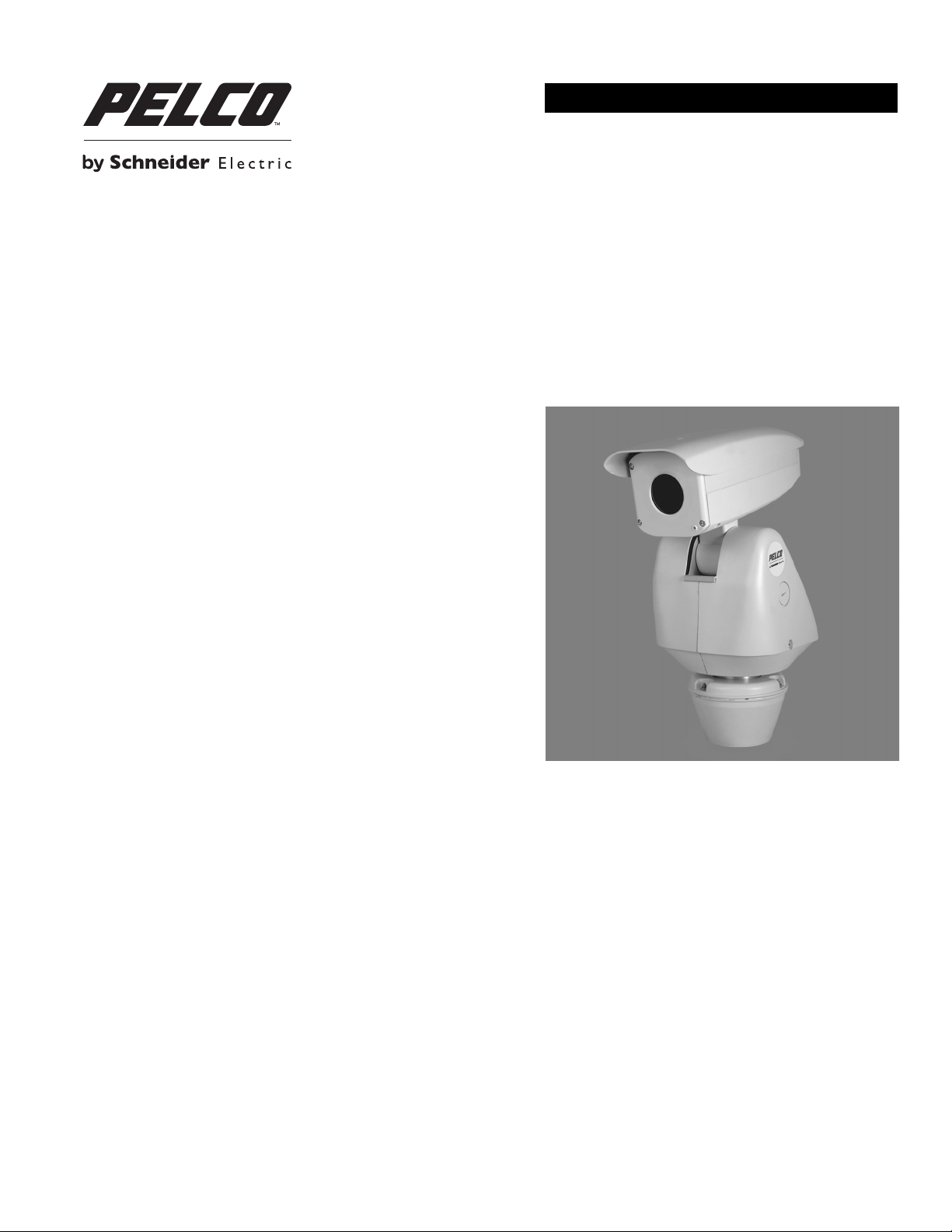
INSTALLATION/OPERATION
Sarix® TI Series Thermal IP Positioning System
C1317M-C (8/13)

Contents
List of Illustrations . . . . . . . . . . . . . . . . . . . . . . . . . . . . . . . . . . . . . . . . . . . . . . . . . . . . . . . . . . . . . . . . . . . . . . . . . . . . . . . . . . . . . . . . . . . . . . . . . . . . . 5
Important Notices . . . . . . . . . . . . . . . . . . . . . . . . . . . . . . . . . . . . . . . . . . . . . . . . . . . . . . . . . . . . . . . . . . . . . . . . . . . . . . . . . . . . . . . . . . . . . . . . . . . . . 6
Legal Notice . . . . . . . . . . . . . . . . . . . . . . . . . . . . . . . . . . . . . . . . . . . . . . . . . . . . . . . . . . . . . . . . . . . . . . . . . . . . . . . . . . . . . . . . . . . . . . . . . . . . . 6
Regulatory Notices . . . . . . . . . . . . . . . . . . . . . . . . . . . . . . . . . . . . . . . . . . . . . . . . . . . . . . . . . . . . . . . . . . . . . . . . . . . . . . . . . . . . . . . . . . . . . . . . 6
Video Quality Caution . . . . . . . . . . . . . . . . . . . . . . . . . . . . . . . . . . . . . . . . . . . . . . . . . . . . . . . . . . . . . . . . . . . . . . . . . . . . . . . . . . . . . . . . . . . . . . 6
Open Source Software Notice . . . . . . . . . . . . . . . . . . . . . . . . . . . . . . . . . . . . . . . . . . . . . . . . . . . . . . . . . . . . . . . . . . . . . . . . . . . . . . . . . . . . . . . 6
Introduction . . . . . . . . . . . . . . . . . . . . . . . . . . . . . . . . . . . . . . . . . . . . . . . . . . . . . . . . . . . . . . . . . . . . . . . . . . . . . . . . . . . . . . . . . . . . . . . . . . . . . . . . . . 7
Built-In Analytics. . . . . . . . . . . . . . . . . . . . . . . . . . . . . . . . . . . . . . . . . . . . . . . . . . . . . . . . . . . . . . . . . . . . . . . . . . . . . . . . . . . . . . . . . . . . . . . . . . 7
Compatible Systems . . . . . . . . . . . . . . . . . . . . . . . . . . . . . . . . . . . . . . . . . . . . . . . . . . . . . . . . . . . . . . . . . . . . . . . . . . . . . . . . . . . . . . . . . . . . . . . 7
Models . . . . . . . . . . . . . . . . . . . . . . . . . . . . . . . . . . . . . . . . . . . . . . . . . . . . . . . . . . . . . . . . . . . . . . . . . . . . . . . . . . . . . . . . . . . . . . . . . . . . . . . . . 8
Getting Started . . . . . . . . . . . . . . . . . . . . . . . . . . . . . . . . . . . . . . . . . . . . . . . . . . . . . . . . . . . . . . . . . . . . . . . . . . . . . . . . . . . . . . . . . . . . . . . . . . . 9
Parts List . . . . . . . . . . . . . . . . . . . . . . . . . . . . . . . . . . . . . . . . . . . . . . . . . . . . . . . . . . . . . . . . . . . . . . . . . . . . . . . . . . . . . . . . . . . . . . . . . . . . . . . . 9
User-Supplied Parts List . . . . . . . . . . . . . . . . . . . . . . . . . . . . . . . . . . . . . . . . . . . . . . . . . . . . . . . . . . . . . . . . . . . . . . . . . . . . . . . . . . . . . . . . . . . . 9
Product Overview. . . . . . . . . . . . . . . . . . . . . . . . . . . . . . . . . . . . . . . . . . . . . . . . . . . . . . . . . . . . . . . . . . . . . . . . . . . . . . . . . . . . . . . . . . . . . . . . . . . . . 10
Removing the Back Cover . . . . . . . . . . . . . . . . . . . . . . . . . . . . . . . . . . . . . . . . . . . . . . . . . . . . . . . . . . . . . . . . . . . . . . . . . . . . . . . . . . . . . . . . . . 11
Installation . . . . . . . . . . . . . . . . . . . . . . . . . . . . . . . . . . . . . . . . . . . . . . . . . . . . . . . . . . . . . . . . . . . . . . . . . . . . . . . . . . . . . . . . . . . . . . . . . . . . . . . . . . 12
Connecting a Relay Device . . . . . . . . . . . . . . . . . . . . . . . . . . . . . . . . . . . . . . . . . . . . . . . . . . . . . . . . . . . . . . . . . . . . . . . . . . . . . . . . . . . . . . . . . 16
Connecting Alarms . . . . . . . . . . . . . . . . . . . . . . . . . . . . . . . . . . . . . . . . . . . . . . . . . . . . . . . . . . . . . . . . . . . . . . . . . . . . . . . . . . . . . . . . . . . . . . . 17
Connecting Audio . . . . . . . . . . . . . . . . . . . . . . . . . . . . . . . . . . . . . . . . . . . . . . . . . . . . . . . . . . . . . . . . . . . . . . . . . . . . . . . . . . . . . . . . . . . . . . . . 19
Supervised Alarms. . . . . . . . . . . . . . . . . . . . . . . . . . . . . . . . . . . . . . . . . . . . . . . . . . . . . . . . . . . . . . . . . . . . . . . . . . . . . . . . . . . . . . . . . . . 17
Unsupervised Alarms. . . . . . . . . . . . . . . . . . . . . . . . . . . . . . . . . . . . . . . . . . . . . . . . . . . . . . . . . . . . . . . . . . . . . . . . . . . . . . . . . . . . . . . . . 18
Alarm Connections. . . . . . . . . . . . . . . . . . . . . . . . . . . . . . . . . . . . . . . . . . . . . . . . . . . . . . . . . . . . . . . . . . . . . . . . . . . . . . . . . . . . . . . . . . . 18
IP Operation . . . . . . . . . . . . . . . . . . . . . . . . . . . . . . . . . . . . . . . . . . . . . . . . . . . . . . . . . . . . . . . . . . . . . . . . . . . . . . . . . . . . . . . . . . . . . . . . . . . . . . . . . 20
Device Configuration Sequence . . . . . . . . . . . . . . . . . . . . . . . . . . . . . . . . . . . . . . . . . . . . . . . . . . . . . . . . . . . . . . . . . . . . . . . . . . . . . . . . . . . . . 20
Minimum System Requirements . . . . . . . . . . . . . . . . . . . . . . . . . . . . . . . . . . . . . . . . . . . . . . . . . . . . . . . . . . . . . . . . . . . . . . . . . . . . . . . . . . . . 20
Accessing the IP Camera . . . . . . . . . . . . . . . . . . . . . . . . . . . . . . . . . . . . . . . . . . . . . . . . . . . . . . . . . . . . . . . . . . . . . . . . . . . . . . . . . . . . . . . . . . 20
Logging On to the Camera . . . . . . . . . . . . . . . . . . . . . . . . . . . . . . . . . . . . . . . . . . . . . . . . . . . . . . . . . . . . . . . . . . . . . . . . . . . . . . . . . . . . . 20
Live Video Page. . . . . . . . . . . . . . . . . . . . . . . . . . . . . . . . . . . . . . . . . . . . . . . . . . . . . . . . . . . . . . . . . . . . . . . . . . . . . . . . . . . . . . . . . . . . . . . . . . 21
Live Video Page Icons . . . . . . . . . . . . . . . . . . . . . . . . . . . . . . . . . . . . . . . . . . . . . . . . . . . . . . . . . . . . . . . . . . . . . . . . . . . . . . . . . . . . . . . . 21
Pan/Tilt Controls . . . . . . . . . . . . . . . . . . . . . . . . . . . . . . . . . . . . . . . . . . . . . . . . . . . . . . . . . . . . . . . . . . . . . . . . . . . . . . . . . . . . . . . . . . . . 22
Selecting a Stream . . . . . . . . . . . . . . . . . . . . . . . . . . . . . . . . . . . . . . . . . . . . . . . . . . . . . . . . . . . . . . . . . . . . . . . . . . . . . . . . . . . . . . . . . . 22
Taking a Snapshot . . . . . . . . . . . . . . . . . . . . . . . . . . . . . . . . . . . . . . . . . . . . . . . . . . . . . . . . . . . . . . . . . . . . . . . . . . . . . . . . . . . . . . . . . . . 23
Settings Page . . . . . . . . . . . . . . . . . . . . . . . . . . . . . . . . . . . . . . . . . . . . . . . . . . . . . . . . . . . . . . . . . . . . . . . . . . . . . . . . . . . . . . . . . . . . . . . . . . . 23
Accessing the Camera Menus. . . . . . . . . . . . . . . . . . . . . . . . . . . . . . . . . . . . . . . . . . . . . . . . . . . . . . . . . . . . . . . . . . . . . . . . . . . . . . . . . . 23
System Tab . . . . . . . . . . . . . . . . . . . . . . . . . . . . . . . . . . . . . . . . . . . . . . . . . . . . . . . . . . . . . . . . . . . . . . . . . . . . . . . . . . . . . . . . . . . . . . . . . . . . . 24
Changing the Device Name . . . . . . . . . . . . . . . . . . . . . . . . . . . . . . . . . . . . . . . . . . . . . . . . . . . . . . . . . . . . . . . . . . . . . . . . . . . . . . . . . . . . 24
Configuring DHCP Time Server Settings . . . . . . . . . . . . . . . . . . . . . . . . . . . . . . . . . . . . . . . . . . . . . . . . . . . . . . . . . . . . . . . . . . . . . . . . . . 25
Configuring Manual Time Server Settings . . . . . . . . . . . . . . . . . . . . . . . . . . . . . . . . . . . . . . . . . . . . . . . . . . . . . . . . . . . . . . . . . . . . . . . . 25
Customizing the Appearance of the Text Overlay. . . . . . . . . . . . . . . . . . . . . . . . . . . . . . . . . . . . . . . . . . . . . . . . . . . . . . . . . . . . . . . . . . . 25
Generating a System Log. . . . . . . . . . . . . . . . . . . . . . . . . . . . . . . . . . . . . . . . . . . . . . . . . . . . . . . . . . . . . . . . . . . . . . . . . . . . . . . . . . . . . . 25
Rebooting the Camera . . . . . . . . . . . . . . . . . . . . . . . . . . . . . . . . . . . . . . . . . . . . . . . . . . . . . . . . . . . . . . . . . . . . . . . . . . . . . . . . . . . . . . . . 26
Restoring All Camera Defaults . . . . . . . . . . . . . . . . . . . . . . . . . . . . . . . . . . . . . . . . . . . . . . . . . . . . . . . . . . . . . . . . . . . . . . . . . . . . . . . . . 26
Downloading a Full Backup of Camera Settings . . . . . . . . . . . . . . . . . . . . . . . . . . . . . . . . . . . . . . . . . . . . . . . . . . . . . . . . . . . . . . . . . . . . 26
Uploading a Backup File to Restore Camera Settings. . . . . . . . . . . . . . . . . . . . . . . . . . . . . . . . . . . . . . . . . . . . . . . . . . . . . . . . . . . . . . . . 26
Network Tab . . . . . . . . . . . . . . . . . . . . . . . . . . . . . . . . . . . . . . . . . . . . . . . . . . . . . . . . . . . . . . . . . . . . . . . . . . . . . . . . . . . . . . . . . . . . . . . . . . . . 27
Changing the Hostname . . . . . . . . . . . . . . . . . . . . . . . . . . . . . . . . . . . . . . . . . . . . . . . . . . . . . . . . . . . . . . . . . . . . . . . . . . . . . . . . . . . . . . 27
Changing the HTTP Port. . . . . . . . . . . . . . . . . . . . . . . . . . . . . . . . . . . . . . . . . . . . . . . . . . . . . . . . . . . . . . . . . . . . . . . . . . . . . . . . . . . . . . . 28
Changing the HTTPS Port. . . . . . . . . . . . . . . . . . . . . . . . . . . . . . . . . . . . . . . . . . . . . . . . . . . . . . . . . . . . . . . . . . . . . . . . . . . . . . . . . . . . . . 28
Changing the RTSP Port. . . . . . . . . . . . . . . . . . . . . . . . . . . . . . . . . . . . . . . . . . . . . . . . . . . . . . . . . . . . . . . . . . . . . . . . . . . . . . . . . . . . . . . 28
Turning On DHCP . . . . . . . . . . . . . . . . . . . . . . . . . . . . . . . . . . . . . . . . . . . . . . . . . . . . . . . . . . . . . . . . . . . . . . . . . . . . . . . . . . . . . . . . . . . . 28
Configuring a Static IPv4 Address . . . . . . . . . . . . . . . . . . . . . . . . . . . . . . . . . . . . . . . . . . . . . . . . . . . . . . . . . . . . . . . . . . . . . . . . . . . . . . . 29
Selecting the Secure Sockets Layer Mode . . . . . . . . . . . . . . . . . . . . . . . . . . . . . . . . . . . . . . . . . . . . . . . . . . . . . . . . . . . . . . . . . . . . . . . . 30
Enabling Secure Shell . . . . . . . . . . . . . . . . . . . . . . . . . . . . . . . . . . . . . . . . . . . . . . . . . . . . . . . . . . . . . . . . . . . . . . . . . . . . . . . . . . . . . . . . 31
Configuring the 802.1x Port Security Settings . . . . . . . . . . . . . . . . . . . . . . . . . . . . . . . . . . . . . . . . . . . . . . . . . . . . . . . . . . . . . . . . . . . . . 31
2 C1317M-C (8/13)

Selecting SNMP Settings . . . . . . . . . . . . . . . . . . . . . . . . . . . . . . . . . . . . . . . . . . . . . . . . . . . . . . . . . . . . . . . . . . . . . . . . . . . . . . . . . . . . . 32
Configuring SNMP V2c . . . . . . . . . . . . . . . . . . . . . . . . . . . . . . . . . . . . . . . . . . . . . . . . . . . . . . . . . . . . . . . . . . . . . . . . . . . . . . . . . . . . . . . 32
Configuring SNMP V3 . . . . . . . . . . . . . . . . . . . . . . . . . . . . . . . . . . . . . . . . . . . . . . . . . . . . . . . . . . . . . . . . . . . . . . . . . . . . . . . . . . . . . . . . 32
Imaging Tab . . . . . . . . . . . . . . . . . . . . . . . . . . . . . . . . . . . . . . . . . . . . . . . . . . . . . . . . . . . . . . . . . . . . . . . . . . . . . . . . . . . . . . . . . . . . . . . . . . . . 33
Selecting the Color Palette . . . . . . . . . . . . . . . . . . . . . . . . . . . . . . . . . . . . . . . . . . . . . . . . . . . . . . . . . . . . . . . . . . . . . . . . . . . . . . . . . . . . 33
Changing the Sharpness . . . . . . . . . . . . . . . . . . . . . . . . . . . . . . . . . . . . . . . . . . . . . . . . . . . . . . . . . . . . . . . . . . . . . . . . . . . . . . . . . . . . . . 34
Changing the Image Enhancement . . . . . . . . . . . . . . . . . . . . . . . . . . . . . . . . . . . . . . . . . . . . . . . . . . . . . . . . . . . . . . . . . . . . . . . . . . . . . . 34
Configuring Noise Filtering . . . . . . . . . . . . . . . . . . . . . . . . . . . . . . . . . . . . . . . . . . . . . . . . . . . . . . . . . . . . . . . . . . . . . . . . . . . . . . . . . . . . 34
Configuring the Recalibration Settings . . . . . . . . . . . . . . . . . . . . . . . . . . . . . . . . . . . . . . . . . . . . . . . . . . . . . . . . . . . . . . . . . . . . . . . . . . . 34
Creating a Preset . . . . . . . . . . . . . . . . . . . . . . . . . . . . . . . . . . . . . . . . . . . . . . . . . . . . . . . . . . . . . . . . . . . . . . . . . . . . . . . . . . . . . . . . . . . . 34
Deleting a Preset . . . . . . . . . . . . . . . . . . . . . . . . . . . . . . . . . . . . . . . . . . . . . . . . . . . . . . . . . . . . . . . . . . . . . . . . . . . . . . . . . . . . . . . . . . . . 35
Creating a Preset Tour . . . . . . . . . . . . . . . . . . . . . . . . . . . . . . . . . . . . . . . . . . . . . . . . . . . . . . . . . . . . . . . . . . . . . . . . . . . . . . . . . . . . . . . . 35
Deleting a Preset from a Tour . . . . . . . . . . . . . . . . . . . . . . . . . . . . . . . . . . . . . . . . . . . . . . . . . . . . . . . . . . . . . . . . . . . . . . . . . . . . . . . . . . 35
Deleting a Preset Tour . . . . . . . . . . . . . . . . . . . . . . . . . . . . . . . . . . . . . . . . . . . . . . . . . . . . . . . . . . . . . . . . . . . . . . . . . . . . . . . . . . . . . . . . 35
Configuring the Speed Profile . . . . . . . . . . . . . . . . . . . . . . . . . . . . . . . . . . . . . . . . . . . . . . . . . . . . . . . . . . . . . . . . . . . . . . . . . . . . . . . . . . 36
Configuring the Pan Center Point . . . . . . . . . . . . . . . . . . . . . . . . . . . . . . . . . . . . . . . . . . . . . . . . . . . . . . . . . . . . . . . . . . . . . . . . . . . . . . . 36
Configuring the Pan Limit Stops . . . . . . . . . . . . . . . . . . . . . . . . . . . . . . . . . . . . . . . . . . . . . . . . . . . . . . . . . . . . . . . . . . . . . . . . . . . . . . . . 36
Configuring the Tilt Limit Stops. . . . . . . . . . . . . . . . . . . . . . . . . . . . . . . . . . . . . . . . . . . . . . . . . . . . . . . . . . . . . . . . . . . . . . . . . . . . . . . . . 36
A/V Streams Tab. . . . . . . . . . . . . . . . . . . . . . . . . . . . . . . . . . . . . . . . . . . . . . . . . . . . . . . . . . . . . . . . . . . . . . . . . . . . . . . . . . . . . . . . . . . . . . . . . 37
Selecting a Video Preset Configuration. . . . . . . . . . . . . . . . . . . . . . . . . . . . . . . . . . . . . . . . . . . . . . . . . . . . . . . . . . . . . . . . . . . . . . . . . . . 37
Configuring a Custom Video Stream Configuration . . . . . . . . . . . . . . . . . . . . . . . . . . . . . . . . . . . . . . . . . . . . . . . . . . . . . . . . . . . . . . . . . 37
Selecting the Audio Configuration Settings . . . . . . . . . . . . . . . . . . . . . . . . . . . . . . . . . . . . . . . . . . . . . . . . . . . . . . . . . . . . . . . . . . . . . . . 39
Users Tab . . . . . . . . . . . . . . . . . . . . . . . . . . . . . . . . . . . . . . . . . . . . . . . . . . . . . . . . . . . . . . . . . . . . . . . . . . . . . . . . . . . . . . . . . . . . . . . . . . . . . . 39
Selecting the Users and Groups Settings . . . . . . . . . . . . . . . . . . . . . . . . . . . . . . . . . . . . . . . . . . . . . . . . . . . . . . . . . . . . . . . . . . . . . . . . . 40
Enabling Remote Mode . . . . . . . . . . . . . . . . . . . . . . . . . . . . . . . . . . . . . . . . . . . . . . . . . . . . . . . . . . . . . . . . . . . . . . . . . . . . . . . . . . . . . . . 40
Creating a New User . . . . . . . . . . . . . . . . . . . . . . . . . . . . . . . . . . . . . . . . . . . . . . . . . . . . . . . . . . . . . . . . . . . . . . . . . . . . . . . . . . . . . . . . . 41
Editing a User. . . . . . . . . . . . . . . . . . . . . . . . . . . . . . . . . . . . . . . . . . . . . . . . . . . . . . . . . . . . . . . . . . . . . . . . . . . . . . . . . . . . . . . . . . . . . . . 41
Deleting a User . . . . . . . . . . . . . . . . . . . . . . . . . . . . . . . . . . . . . . . . . . . . . . . . . . . . . . . . . . . . . . . . . . . . . . . . . . . . . . . . . . . . . . . . . . . . . 41
Events Tab. . . . . . . . . . . . . . . . . . . . . . . . . . . . . . . . . . . . . . . . . . . . . . . . . . . . . . . . . . . . . . . . . . . . . . . . . . . . . . . . . . . . . . . . . . . . . . . . . . . . . . 42
Sources . . . . . . . . . . . . . . . . . . . . . . . . . . . . . . . . . . . . . . . . . . . . . . . . . . . . . . . . . . . . . . . . . . . . . . . . . . . . . . . . . . . . . . . . . . . . . . . . . . . 43
Handlers. . . . . . . . . . . . . . . . . . . . . . . . . . . . . . . . . . . . . . . . . . . . . . . . . . . . . . . . . . . . . . . . . . . . . . . . . . . . . . . . . . . . . . . . . . . . . . . . . . . 45
Analytic Configuration . . . . . . . . . . . . . . . . . . . . . . . . . . . . . . . . . . . . . . . . . . . . . . . . . . . . . . . . . . . . . . . . . . . . . . . . . . . . . . . . . . . . . . . . . . . . 49
Profiles . . . . . . . . . . . . . . . . . . . . . . . . . . . . . . . . . . . . . . . . . . . . . . . . . . . . . . . . . . . . . . . . . . . . . . . . . . . . . . . . . . . . . . . . . . . . . . . . . . . . 49
Calibrate Scene . . . . . . . . . . . . . . . . . . . . . . . . . . . . . . . . . . . . . . . . . . . . . . . . . . . . . . . . . . . . . . . . . . . . . . . . . . . . . . . . . . . . . . . . . . . . . 50
Behaviors . . . . . . . . . . . . . . . . . . . . . . . . . . . . . . . . . . . . . . . . . . . . . . . . . . . . . . . . . . . . . . . . . . . . . . . . . . . . . . . . . . . . . . . . . . . . . . . . . . 51
Zones . . . . . . . . . . . . . . . . . . . . . . . . . . . . . . . . . . . . . . . . . . . . . . . . . . . . . . . . . . . . . . . . . . . . . . . . . . . . . . . . . . . . . . . . . . . . . . . . . . . . . 52
Adaptive Motion . . . . . . . . . . . . . . . . . . . . . . . . . . . . . . . . . . . . . . . . . . . . . . . . . . . . . . . . . . . . . . . . . . . . . . . . . . . . . . . . . . . . . . . . . . . . 53
Camera Sabotage . . . . . . . . . . . . . . . . . . . . . . . . . . . . . . . . . . . . . . . . . . . . . . . . . . . . . . . . . . . . . . . . . . . . . . . . . . . . . . . . . . . . . . . . . . . 54
Loitering Detection . . . . . . . . . . . . . . . . . . . . . . . . . . . . . . . . . . . . . . . . . . . . . . . . . . . . . . . . . . . . . . . . . . . . . . . . . . . . . . . . . . . . . . . . . . 55
Object Counting . . . . . . . . . . . . . . . . . . . . . . . . . . . . . . . . . . . . . . . . . . . . . . . . . . . . . . . . . . . . . . . . . . . . . . . . . . . . . . . . . . . . . . . . . . . . . 56
Stopped Vehicle. . . . . . . . . . . . . . . . . . . . . . . . . . . . . . . . . . . . . . . . . . . . . . . . . . . . . . . . . . . . . . . . . . . . . . . . . . . . . . . . . . . . . . . . . . . . . 57
Analog Operation. . . . . . . . . . . . . . . . . . . . . . . . . . . . . . . . . . . . . . . . . . . . . . . . . . . . . . . . . . . . . . . . . . . . . . . . . . . . . . . . . . . . . . . . . . . . . . . . . . . . . 58
Operating Notes . . . . . . . . . . . . . . . . . . . . . . . . . . . . . . . . . . . . . . . . . . . . . . . . . . . . . . . . . . . . . . . . . . . . . . . . . . . . . . . . . . . . . . . . . . . . . . . . . 59
Environmental Range. . . . . . . . . . . . . . . . . . . . . . . . . . . . . . . . . . . . . . . . . . . . . . . . . . . . . . . . . . . . . . . . . . . . . . . . . . . . . . . . . . . . . . . . . 59
Pan/Tilt Functions . . . . . . . . . . . . . . . . . . . . . . . . . . . . . . . . . . . . . . . . . . . . . . . . . . . . . .
. . . . . . . . . . . . . . . . . . . . . . . . . . . . . . . . . . . . . 59
Turbo Mode . . . . . . . . . . . . . . . . . . . . . . . . . . . . . . . . . . . . . . . . . . . . . . . . . . . . . . . . . . . . . . . . . . . . . . . . . . . . . . . . . . . . . . . . . . . . . . . . 59
Preset Functions. . . . . . . . . . . . . . . . . . . . . . . . . . . . . . . . . . . . . . . . . . . . . . . . . . . . . . . . . . . . . . . . . . . . . . . . . . . . . . . . . . . . . . . . . . . . . 59
Zones . . . . . . . . . . . . . . . . . . . . . . . . . . . . . . . . . . . . . . . . . . . . . . . . . . . . . . . . . . . . . . . . . . . . . . . . . . . . . . . . . . . . . . . . . . . . . . . . . . . . . 59
Patterns . . . . . . . . . . . . . . . . . . . . . . . . . . . . . . . . . . . . . . . . . . . . . . . . . . . . . . . . . . . . . . . . . . . . . . . . . . . . . . . . . . . . . . . . . . . . . . . . . . . 59
Park . . . . . . . . . . . . . . . . . . . . . . . . . . . . . . . . . . . . . . . . . . . . . . . . . . . . . . . . . . . . . . . . . . . . . . . . . . . . . . . . . . . . . . . . . . . . . . . . . . . . . . 60
Accessing the Main Menu with Preset 95 . . . . . . . . . . . . . . . . . . . . . . . . . . . . . . . . . . . . . . . . . . . . . . . . . . . . . . . . . . . . . . . . . . . . . . . . 60
Configuration . . . . . . . . . . . . . . . . . . . . . . . . . . . . . . . . . . . . . . . . . . . . . . . . . . . . . . . . . . . . . . . . . . . . . . . . . . . . . . . . . . . . . . . . . . . . . . . . . . . 62
Az/El. . . . . . . . . . . . . . . . . . . . . . . . . . . . . . . . . . . . . . . . . . . . . . . . . . . . . . . . . . . . . . . . . . . . . . . . . . . . . . . . . . . . . . . . . . . . . . . . . . . . . . 62
Az/El Line . . . . . . . . . . . . . . . . . . . . . . . . . . . . . . . . . . . . . . . . . . . . . . . . . . . . . . . . . . . . . . . . . . . . . . . . . . . . . . . . . . . . . . . . . . . . . . . . . . 63
Azimuth Zero . . . . . . . . . . . . . . . . . . . . . . . . . . . . . . . . . . . . . . . . . . . . . . . . . . . . . . . . . . . . . . . . . . . . . . . . . . . . . . . . . . . . . . . . . . . . . . . 64
Camera Mode . . . . . . . . . . . . . . . . . . . . . . . . . . . . . . . . . . . . . . . . . . . . . . . . . . . . . . . . . . . . . . . . . . . . . . . . . . . . . . . . . . . . . . . . . . . . . . 64
Direction. . . . . . . . . . . . . . . . . . . . . . . . . . . . . . . . . . . . . . . . . . . . . . . . . . . . . . . . . . . . . . . . . . . . . . . . . . . . . . . . . . . . . . . . . . . . . . . . . . . 65
Direction Line. . . . . . . . . . . . . . . . . . . . . . . . . . . . . . . . . . . . . . . . . . . . . . . . . . . . . . . . . . . . . . . . . . . . . . . . . . . . . . . . . . . . . . . . . . . . . . . 65
Display Duration . . . . . . . . . . . . . . . . . . . . . . . . . . . . . . . . . . . . . . . . . . . . . . . . . . . . . . . . . . . . . . . . . . . . . . . . . . . . . . . . . . . . . . . . . . . . 66
Factory Reset . . . . . . . . . . . . . . . . . . . . . . . . . . . . . . . . . . . . . . . . . . . . . . . . . . . . . . . . . . . . . . . . . . . . . . . . . . . . . . . . . . . . . . . . . . . . . . . 67
Pan Limits. . . . . . . . . . . . . . . . . . . . . . . . . . . . . . . . . . . . . . . . . . . . . . . . . . . . . . . . . . . . . . . . . . . . . . . . . . . . . . . . . . . . . . . . . . . . . . . . . . 67
C1317M-C (8/13) 3

Park Time . . . . . . . . . . . . . . . . . . . . . . . . . . . . . . . . . . . . . . . . . . . . . . . . . . . . . . . . . . . . . . . . . . . . . . . . . . . . . . . . . . . . . . . . . . . . . . . . . . 69
Power Up Mode . . . . . . . . . . . . . . . . . . . . . . . . . . . . . . . . . . . . . . . . . . . . . . . . . . . . . . . . . . . . . . . . . . . . . . . . . . . . . . . . . . . . . . . . . . . . . 69
Speed Profile . . . . . . . . . . . . . . . . . . . . . . . . . . . . . . . . . . . . . . . . . . . . . . . . . . . . . . . . . . . . . . . . . . . . . . . . . . . . . . . . . . . . . . . . . . . . . . . 70
Tilt Limits . . . . . . . . . . . . . . . . . . . . . . . . . . . . . . . . . . . . . . . . . . . . . . . . . . . . . . . . . . . . . . . . . . . . . . . . . . . . . . . . . . . . . . . . . . . . . . . . . . 71
Zones . . . . . . . . . . . . . . . . . . . . . . . . . . . . . . . . . . . . . . . . . . . . . . . . . . . . . . . . . . . . . . . . . . . . . . . . . . . . . . . . . . . . . . . . . . . . . . . . . . . . . 72
Specifications . . . . . . . . . . . . . . . . . . . . . . . . . . . . . . . . . . . . . . . . . . . . . . . . . . . . . . . . . . . . . . . . . . . . . . . . . . . . . . . . . . . . . . . . . . . . . . . . . . . . . . . 73
Appendix . . . . . . . . . . . . . . . . . . . . . . . . . . . . . . . . . . . . . . . . . . . . . . . . . . . . . . . . . . . . . . . . . . . . . . . . . . . . . . . . . . . . . . . . . . . . . . . . . . . . . . . . . . . 77
4 C1317M-C (8/13)

List of Illustrations
1 Camera Features. . . . . . . . . . . . . . . . . . . . . . . . . . . . . . . . . . . . . . . . . . . . . . . . . . . . . . . . . . . . . . . . . . . . . . . . . . . . . . . . . . . . . . . . . . . . . . . . . 10
2 Removing the Back Cover . . . . . . . . . . . . . . . . . . . . . . . . . . . . . . . . . . . . . . . . . . . . . . . . . . . . . . . . . . . . . . . . . . . . . . . . . . . . . . . . . . . . . . . . . . 11
3 Removing the Power Module . . . . . . . . . . . . . . . . . . . . . . . . . . . . . . . . . . . . . . . . . . . . . . . . . . . . . . . . . . . . . . . . . . . . . . . . . . . . . . . . . . . . . . . 12
4 Attaching the Base . . . . . . . . . . . . . . . . . . . . . . . . . . . . . . . . . . . . . . . . . . . . . . . . . . . . . . . . . . . . . . . . . . . . . . . . . . . . . . . . . . . . . . . . . . . . . . . 13
5 Routing Wires and Cables . . . . . . . . . . . . . . . . . . . . . . . . . . . . . . . . . . . . . . . . . . . . . . . . . . . . . . . . . . . . . . . . . . . . . . . . . . . . . . . . . . . . . . . . . 13
6 Attaching Base and Pan/Tilt. . . . . . . . . . . . . . . . . . . . . . . . . . . . . . . . . . . . . . . . . . . . . . . . . . . . . . . . . . . . . . . . . . . . . . . . . . . . . . . . . . . . . . . . 15
7 Setting DIP Switches . . . . . . . . . . . . . . . . . . . . . . . . . . . . . . . . . . . . . . . . . . . . . . . . . . . . . . . . . . . . . . . . . . . . . . . . . . . . . . . . . . . . . . . . . . . . . 16
8 Wiring Diagram for Relay A . . . . . . . . . . . . . . . . . . . . . . . . . . . . . . . . . . . . . . . . . . . . . . . . . . . . . . . . . . . . . . . . . . . . . . . . . . . . . . . . . . . . . . . . 16
9 Wiring Diagram for Relay B . . . . . . . . . . . . . . . . . . . . . . . . . . . . . . . . . . . . . . . . . . . . . . . . . . . . . . . . . . . . . . . . . . . . . . . . . . . . . . . . . . . . . . . . 17
10 Supervised Alarm Conditions . . . . . . . . . . . . . . . . . . . . . . . . . . . . . . . . . . . . . . . . . . . . . . . . . . . . . . . . . . . . . . . . . . . . . . . . . . . . . . . . . . . . . . . 17
11 Supervised Alarm Input Wiring . . . . . . . . . . . . . . . . . . . . . . . . . . . . . . . . . . . . . . . . . . . . . . . . . . . . . . . . . . . . . . . . . . . . . . . . . . . . . . . . . . . . . 17
12 Unsupervised Alarm Conditions . . . . . . . . . . . . . . . . . . . . . . . . . . . . . . . . . . . . . . . . . . . . . . . . . . . . . . . . . . . . . . . . . . . . . . . . . . . . . . . . . . . . . 18
13 Normally Closed and Normally Open Unsupervised Alarm Input Wiring . . . . . . . . . . . . . . . . . . . . . . . . . . . . . . . . . . . . . . . . . . . . . . . . . . . . . 18
14 Alarm Connections . . . . . . . . . . . . . . . . . . . . . . . . . . . . . . . . . . . . . . . . . . . . . . . . . . . . . . . . . . . . . . . . . . . . . . . . . . . . . . . . . . . . . . . . . . . . . . . 18
15 Line-In Audio Wiring. . . . . . . . . . . . . . . . . . . . . . . . . . . . . . . . . . . . . . . . . . . . . . . . . . . . . . . . . . . . . . . . . . . . . . . . . . . . . . . . . . . . . . . . . . . . . . 19
16 Configuration Screen . . . . . . . . . . . . . . . . . . . . . . . . . . . . . . . . . . . . . . . . . . . . . . . . . . . . . . . . . . . . . . . . . . . . . . . . . . . . . . . . . . . . . . . . . . . . . 58
17 Analog Menu Tree . . . . . . . . . . . . . . . . . . . . . . . . . . . . . . . . . . . . . . . . . . . . . . . . . . . . . . . . . . . . . . . . . . . . . . . . . . . . . . . . . . . . . . . . . . . . . . . 62
18 Pedestal Mount Models . . . . . . . . . . . . . . . . . . . . . . . . . . . . . . . . . . . . . . . . . . . . . . . . . . . . . . . . . . . . . . . . . . . . . . . . . . . . . . . . . . . . . . . . . . . 75
19 Wall Mount Models . . . . . . . . . . . . . . . . . . . . . . . . . . . . . . . . . . . . . . . . . . . . . . . . . . . . . . . . . . . . . . . . . . . . . . . . . . . . . . . . . . . . . . . . . . . . . . 76
20 Pedestal Mounting Pattern . . . . . . . . . . . . . . . . . . . . . . . . . . . . . . . . . . . . . . . . . . . . . . . . . . . . . . . . . . . . . . . . . . . . . . . . . . . . . . . . . . . . . . . . . 76
21 Wall Mounting Pattern . . . . . . . . . . . . . . . . . . . . . . . . . . . . . . . . . . . . . . . . . . . . . . . . . . . . . . . . . . . . . . . . . . . . . . . . . . . . . . . . . . . . . . . . . . . . 76
C1317M-C (8/13) 5

Important Notices
LEGAL NOTICE
SOME PELCO EQUIPMENT CONTAINS, AND THE SOFTWARE ENABLES, AUDIO/VISUAL AND RECORDING CAPABILITIES, THE IMPROPER USE OF
WHICH MAY SUBJECT YOU TO CIVIL AND CRIMINAL PENALTIES. APPLICABLE LAWS REGARDING THE USE OF SUCH CAPABILITIES VARY
BETWEEN JURISDICTIONS AND MAY REQUIRE, AMONG OTHER THINGS, EXPRESS WRITTEN CONSENT FROM RECORDED SUBJECTS. YOU
ARE SOLELY RESPONSIBLE FOR INSURING STRICT COMPLIANCE WITH SUCH LAWS AND FOR STRICT ADHERENCE TO ANY/ALL RIGHTS OF
PRIVACY AND PERSONALTY. USE OF THIS EQUIPMENT AND/OR SOFTWARE FOR ILLEGAL SURVEILLANCE OR MONITORING SHALL BE DEEMED
UNAUTHORIZED USE IN VIOLATION OF THE END USER SOFTWARE AGREEMENT AND RESULT IN THE IMMEDIATE TERMINATION OF YOUR
LICENSE RIGHTS THEREUNDER.
REGULATORY NOTICES
This device complies with Part 15 of the FCC Rules. Operation is subject to the following two conditions: (1) this device may not cause harmful
interference, and (2) this device must accept any interference received, including interference that may cause undesired operation.
RADIO AND TELEVISION INTERFERENCE
This equipment has been tested and found to comply with the limits of a Class A digital device, pursuant to Part 15 of the FCC rules. These limits
are designed to provide reasonable protection against harmful interference when the equipment is operated in a commercial environment.
This equipment generates, uses, and can radiate radio frequency energy and, if not installed and used in accordance with the instruction manual,
may cause harmful interference to radio communications. Operation of this equipment in a residential area is likely to cause harmful interference
in which case the user will be required to correct the interference at his own expense.
Changes and Modifications not expressly approved by the manufacturer or registrant of this equipment can void your authority to operate this
equipment under Federal Communications Commission’s rules.
This Class A digital apparatus complies with Canadian ICES-003.
Cet appareil numérique de la classe A est conforme à la norme NMB-003 du Canada.
VIDEO QUALITY CAUTION
FRAME RATE NOTICE REGARDING USER-SELECTED OPTIONS
Pelco systems are capable of providing high quality video for both live viewing and playback. However, the systems can be used in lower quality
modes, which can degrade picture quality, to allow for a slower rate of data transfer and to reduce the amount of video data stored. The picture
quality can be degraded by either lowering the resolution, reducing the picture rate, or both. A picture degraded by having a reduced resolution
may result in an image that is less clear or even indiscernible. A picture degraded by reducing the picture rate has fewer frames per second,
which can result in images that appear to jump or move more quickly than normal during playback. Lower frame rates may result in a key event
not being recorded by the system.
Judgment as to the suitability of the products for users’ purposes is solely the users’ responsibility. Users shall determine the suitability of the
products for their own intended application, picture rate and picture quality. In the event users intend to use the video for evidentiary purposes in
a judicial proceeding or otherwise, users should consult with their attorney regarding any particular requirements for such use.
OPEN SOURCE SOFTWARE NOTICE
This product includes certain open source or other software originated from third parties that is subject to the GNU General Public License (GPL),
GNU Library/Lesser General Public License (LGPL) and different and/or additional copyright licenses, disclaimers, and notices.
The exact terms of GPL, LGPL, and some other licenses are provided to you with this product. Please refer to the exact terms of the GPL and LGPL
at http://www.fsf.org (Free Software Foundation) or http://www.opensource.org (Open Source Initiative) regarding your rights under said license.
You may obtain a complete corresponding machine-readable copy of the source code of such software under the GPL or LGPL by sending your
request to digitalsupport@pelco.com; the subject line should read Source Code Request. You will then receive an email with a link for you to
download the source code.
This offer is valid for a period of three (3) years from the date of the distribution of this product by Pelco.
6 C1317M-C (8/13)

Introduction
The Sarix® TI Series combines the power of an advanced thermal imaging device with the precision of an Esprit® positioning system. At the core
of the Sarix TI Series is an uncooled, sun-safe, amorphous silicon microbolometer, long wave infrared (LWIR) camera. Every Sarix TI Series
features IP and analog outputs in the same package. The pan/tilt positioner can be controlled using IP or analog systems that use Coaxitron® or
RS-422 Pelco D and Pelco P protocols.
The Sarix TI Series provides outstanding sensitivity below 50 mK. It is capable of multiple display formats, including white hot, black hot, and
rainbow. The Sarix TI Series is available with multiple lens configurations for effective deployment in a wide range of applications.
The camera features open architecture connectivity to third-party software. Pelco offers an application programming interface (API) and software
development kit (SDK) that enables third-party systems to interface with Pelco's IP cameras. The camera is also compatible with Endura
and Digital Sentry® to record, manage, configure, and view multiple live streams.
BUILT-IN ANALYTICS
When used in an IP video system, the Sarix TI Series is preloaded with user-configurable behaviors. The device is capable of running up to three
behaviors at the same time; however, the number of behaviors is limited to the available processing power of the camera and the type of analytic
being used.
Pelco analytics are configured and enabled using a standard Web browser. Refer to Analytic Configuration on page 47 for instructions on how to
configure and enable Pelco analytics.
COMPATIBLE SYSTEMS
The device can also be used with an Endura, DX Series, or Digital Sentry system. It also works with many third-party systems with Pelco’s API
and the ONVIF API. For detailed instructions on configuring the device using one of these systems, refer to the manual shipped with the system.
Go to partnerfirst.pelco.com for a list of compatible products and partners.
®
, DX,
C1317M-C (8/13) 7

MODELS
640 x 480 Resolution
Lens Format
35 mm
50 mm
100 mm
384 x 288 Resolution
Lens Format
14.25 mm
35 mm
50 mm
100 mm
Pedestal Mount Wall Mount
24 VAC 120/230 VAC 24 VAC 120/230 VAC
NTSC ESTI635-2N ESTI635-5N ESTI635-2W ESTI635-5W
PAL ESTI635-2N-X ESTI635-5N-X ESTI635-2W-X ESTI635-5W-X
PAL, 8.33 ips ESTI635-2N-X1 ESTI635-5N-X1 ESTI635-2W-X1 ESTI635-5W-X1
NTSC ESTI650-2N ESTI650-5N ESTI650-2W ESTI650-5W
PAL ESTI650-2N-X ESTI650-5N-X ESTI650-2W-X ESTI650-5W-X
PAL, 8.33 ips ESTI650-2N-X1 ESTI650-5N-X1 ESTI650-2W-X1 ESTI650-5W-X1
NTSC ESTI6100-2N ESTI6100-5N ESTI6100-2W ESTI6100-5W
PAL ESTI6100-2N-X ESTI6100-5N-X ESTI6100-2W-X ESTI6100-5W-X
PAL, 8.33 ips ESTI6100-2N-X1 ESTI6100-5N-X1 ESTI6100-2W-X1 ESTI6100-5W-X1
Pedestal Mount Wall Mount
24 VAC 120/230 VAC 24 VAC 120/230 VAC
NTSC ESTI314-2N ESTI314-5N ESTI314-2W ESTI314-5W
PAL ESTI314-2N-X ESTI314-5N-X ESTI314-2W-X ESTI314-5W-X
PAL, 8.33 ips ESTI314-2N-X1 ESTI314-5N-X1 ESTI314-2W-X1 ESTI314-5W-X1
NTSC ESTI335-2N ESTI335-5N ESTI335-2W ESTI335-5W
PAL ESTI335-2N-X ESTI335-5N-X ESTI335-2W-X ESTI335-5W-X
PAL, 8.33 ips ESTI335-2N-X1 ESTI335-5N-X1 ESTI335-2W-X1 ESTI335-5W-X1
NTSC ESTI350-2N ESTI350-5N ESTI350-2W ESTI350-5W
PAL ESTI350-2N-X ESTI350-5N-X ESTI350-2W-X ESTI350-5W-X
PAL, 8.33 ips ESTI350-2N-X1 ESTI350-5N-X1 ESTI350-2W-X1 ESTI350-5W-X1
NTSC ESTI3100-2N ESTI3100-5N EST3100-2W ESTI3100-5W
PAL ESTI3100-2N-X ESTI3100-5N-X ESTI3100-2W-X ESTI3100-5W-X
PAL, 8.33 ips ESTI3100-2N-X1 ESTI3100-5N-X1 ESTI3100-2W-X1 ESTI3100-5W-X1
8 C1317M-C (8/13)

GETTING STARTED
Before installing your camera, thoroughly familiarize yourself with the information in this section.
NOTES:
• While this camera can operate in both IP and analog modes, it is recommended that you use the camera in only one of these modes at any
given time, not both.
• Pelco recommends connecting the camera to a network that uses a Dynamic Host Configuration Protocol (DHCP) server to address devices.
• Do not use a network hub when configuring the network settings for the camera.
• To ensure secure access to the IP camera, place the camera behind a firewall when it is connected to a network.
PARTS LIST
The following parts are supplied:
Qty Description
1 Camera, pan/tilt, and power module
1 Quick Start Guide
1 Resource disc
3 MAC address labels (extra)
1 T20 security driver bit
USER-SUPPLIED PARTS LIST
Installation tools and mounting hardware are needed but not supplied.
C1317M-C (8/13) 9
Product Overview
ì
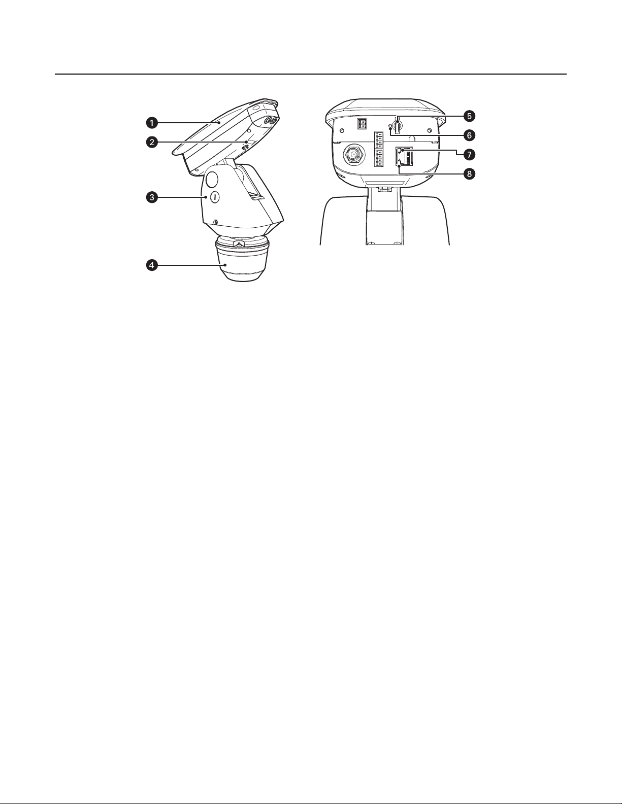
Camera and Enclosure: Powder-coated aluminum IP66 rated enclosure with sun shroud protects the camera in both indoor and outdoor
environments.
î
Product Label: Lists the model number, date code, serial number, and Media Access Control (MAC) address. This information might be
required for setup.
ï
Pan/Tilt: Esprit pan/tilt positioner
Figure 1. Camera Features
ñ
Power Module: Provides power to the unit. If you are using a TXB Series translator board, it will be installed into the power module.
ó
Micro SD Card Slot: Saves a snapshot image to a micro SD card based on alarm activity.
NOTE: The micro SD card must be formatted as FAT32. Other formats are not compatible with the camera.
r
Reset Button: Reboots the camera or restores the camera’s factory default settings. This button is recessed. Using a small tool, such as a
paper clip, press and release the reset button once to reboot the camera. Press and hold the reset button for 10 seconds to restore the
camera to the factory default settings.
s
Ethernet Link LED: Flashes green to indicate that a live network connection is established.
t
Ethernet Activity LED: Glows solid green to indicate that data is being transmitted or received by the camera.
NOTE: Figure 1 shows the camera with the back cover removed. The connectors on the back of the camera are not active. These connections
must be made using the color-coded wire harness attached to the pan/tilt. Refer to Installation on page 12 for more information.
10 C1317M-C (8/13)

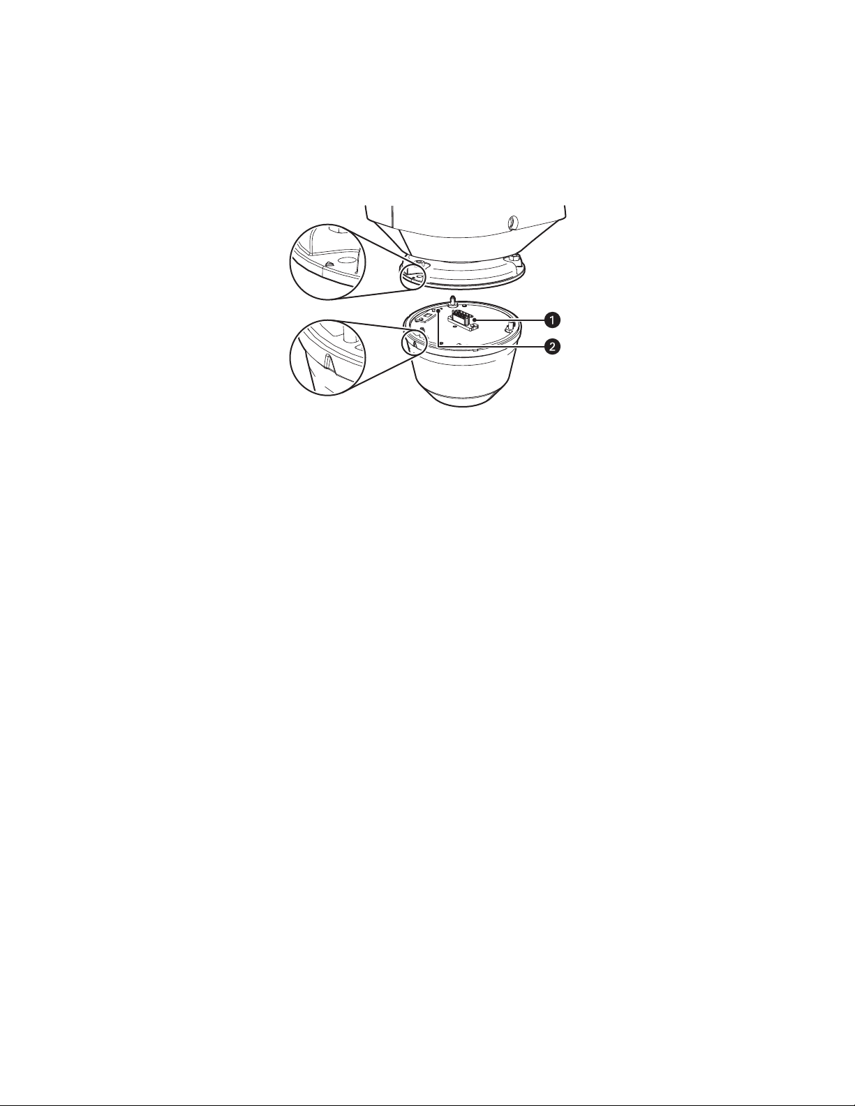
REMOVING THE BACK COVER
To access the micro SD card slot, reset buttons, and Ethernet LEDs, you must first remove the back cover:
1. Loosen the two T20 security screws using a T20 security driver bit (supplied).
2. Remove the back cover.
Figure 2. Removing the Back Cover
C1317M-C (8/13) 11
Installation
1. When installing the device, allow for sufficient clearance between the top of the unit and overhead obstructions. This will prevent
interference when the enclosure is driven to its maximum tilt angles.Refer to the dimension drawings in Specifications on page 73
NOTE: Do not install the system behind a window or other glass. Glass is opaque to long wave infrared and will block the camera’s view.
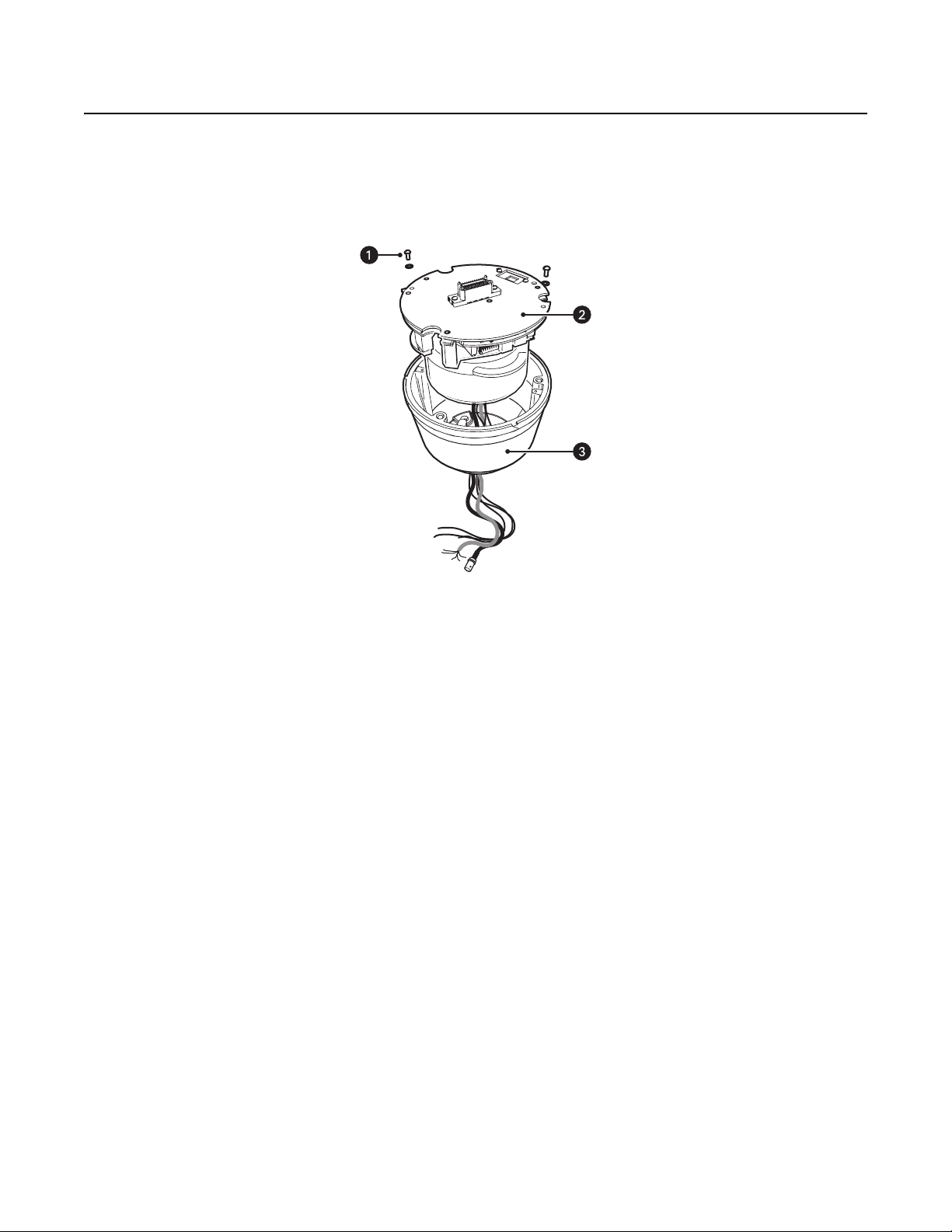
2. Remove the power module from the base of the system by loosening the two Phillips screws and lifting the module.
Figure 3. Removing the Power Module
ì
Phillips Screws
î
Power Module
ï
Base
12 C1317M-C (8/13)
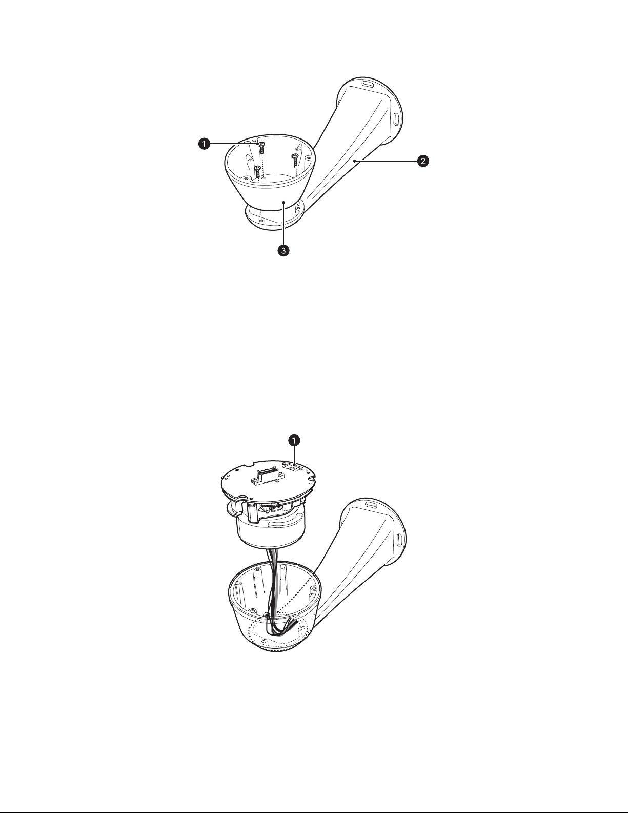
3. Attach the base of the system to a recommended mount with the three flathead 10-32 x 1/2-inch screws and washers (supplied).
Figure 4. Attaching the Base
ì
Flathead Mounting Screws
î
Mount
ï
Base
4. If you are installing an optional TXB Series translator board, you must do so before you reinstall the power module to the base. Refer to the
installation manual shipped with the translator board for more information.
5. Route the wires and cables through the center of the mount. Reinstall the power module into the base. The power module can be
positioned in the base in only one orientation.
Figure 5. Routing Wires and Cables
ì
120/230 Voltage Selector Switch
6. 120/230 VAC models only: Set the 120/230 voltage selector switch on the power module to the appropriate voltage.
C1317M-C (8/13) 13

7. Connect all wires and cables.
a. Connect the appropriate power wiring to AC power. Use the two supplied clamp connectors.
Tab l e A . Power Wire Colors
120/230 VAC 24 VAC
Black wire Input (AC Line) Black wire AC HI (HOT)
White wire AC Neutral Red wire AC LO (NEUT)
Green wire Ground
b. Connect the video cable.
• Analog installations: Connect the video coaxial cable to the BNC connector.
• IP installations: Connect the video Ethernet cable.
Table B. Ethernet Wire Colors
Orange/white wire TX+
Orange wire TX–
Green/white wire RX+
Green wire RX–
Brown wire N.C.
Brown/white wire N.C.
Blue wire N.C.
Blue/white wire N.C.
c. Connect the wiring for a 2-wire or 4-wire control system. This step does not apply to Coaxitron control systems.
Table C. Control Wire Colors
Green wire RX–
Green/white wire RX+
Brown wire TX–
Brown/white wire TX+
d. Optional: Connect the AUX 2 wiring. Refer to Connecting a Relay Device on page 16 and Connecting Alarms on page 17 for more
detailed information.
Table D. AUX 2 Wire Colors
Violet wire Alarm 1
Yellow wire Alarm 2
Orange wire Alarm 3
Blue wire Alarm COM
Brown wire Relay A1
Green wire Relay A2
Red wire COM
White wire N.O.
Black wire N.C.
e. Optional: Connect the audio wiring. Refer to Connecting Audio on page 19 for more detailed information.
Table E. Audio Wire Colors
Orange/white wire Mic Power +
Orange wire Mic Power –
Blue/white wire Audio In +
Blue wire Audio In –
14 C1317M-C (8/13)
8. Install the mount. Refer to the installation manual supplied with the mount for more information.
9. Turn on the system power. The red power LED is located on the top of the power module (refer to Figure 6 on page 15). If the red LED glows,
turn off the power and proceed to the next step.
NOTE: There might be a delay of approximately 3 minutes between power up and video being displayed in analog installations.
10. Align the triangle mark on the pan/tilt with the triangle mark on the base to ensure that the system connector on the pan/tilt and the base
are also aligned.
Figure 6. Attaching Base and Pan/Tilt
ì
System Connector
î
Power LED
11. Attach the pan/tilt to the base with three 1/4-20 nuts and washers (supplied).
12. Set the receiver address and system baud rate by configuring DIP switches SW1 and SW2.
NOTE: If you have a Coaxitron controller, refer to Appendix on page 77 for switch settings.
To set the DIP switches:
a. Remove the plug from the left cover of the pan/tilt. It is not necessary to remove the pan/tilt cover.
b. Set the baud rate (SW1) and receiver address (SW2). For switch settings, refer to Appendix on page 77.
c. Replace the plug.
C1317M-C (8/13) 15

13. Refer to IP Operation on page 20 and Analog Operation on page 58 for instructions on how to use your Sarix TI Series system.
NC
NO
COM
USER ACCESSORYSARIX TI
CONNECTING A RELAY DEVICE
NOTE: Relays must be configured using the Web interface.
The Sarix TI has two outputs for activating external devices. It supports both momentary and continuous relay operation.
ON
OFF
ON
OFF
Figure 7. Setting DIP Switches
SW2 SW1
1 2 3 4 5 6 7 8
1 2 3 4 5 6 7 8
DIP SWITCHES
You can operate the relays interactively during an active connection, or they can operate automatically to coincide with certain events. Typical
applications include turning on lights or other electrical devices or activating a door, gate, or lock.
WARNING: Do not exceed the maximum relay ratings of 60 V, 600 mA for Relay A and 60 VDC, 125 VAC for Relay B.
Figure 8. Wiring Diagram for Relay A
16 C1317M-C (8/13)
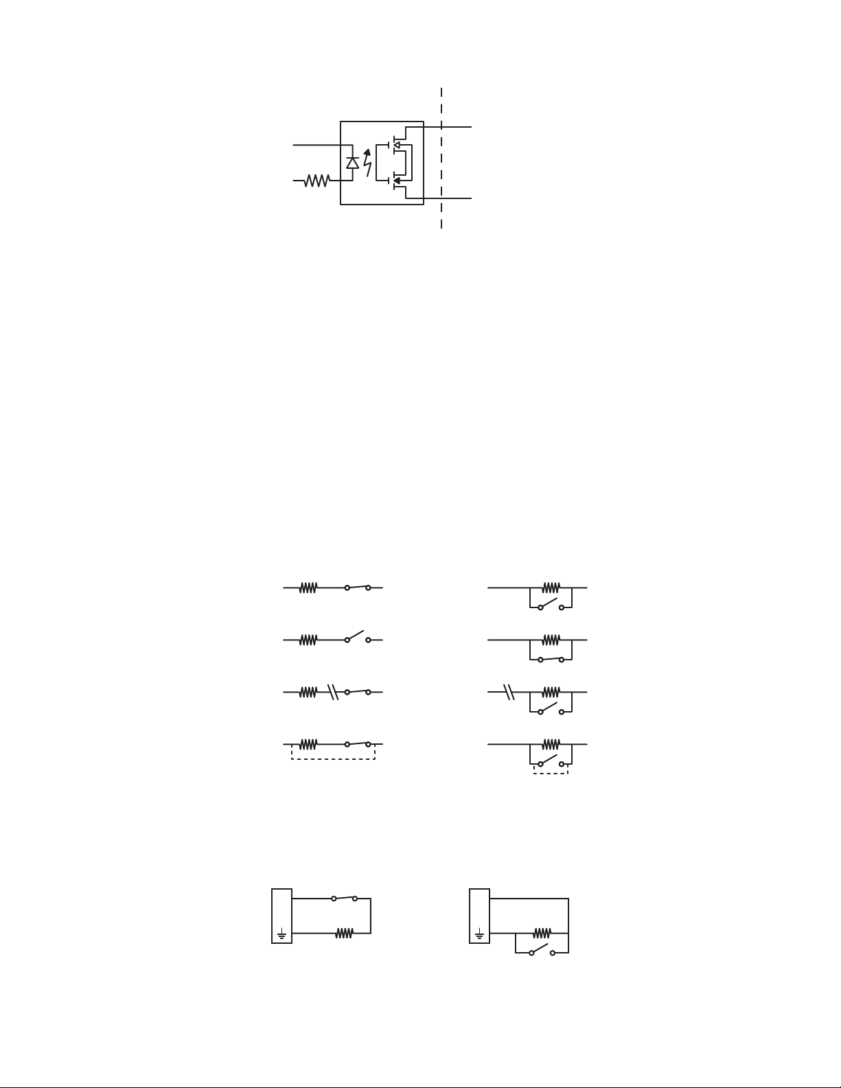
CONNECTING ALARMS
1 KΩ
A
1
1 KΩ
A
1
NORMALLY OPENNORMALLY CLOSED
NOTE: Alarms must be configured using the Web interface.
The Sarix TI provides three alarm inputs for external signaling devices, such as door contacts or motion detectors. Both normally open and
normally closed devices are supported.
SUPERVISED ALARMS
When an alarm is configured as a supervised alarm, the Sarix TI maintains a constant electrical current through the alarm circuit
(3.3 VDC, 1 kohm). If the alarm circuit length changes, due to an electrical short or a bypass, the voltage fluctuates from its normal state and
activates an alarm.
NOTE: Install the 1-kohm resistor as close to the switch as possible.
USER ACCESSORYSARIX TI
A1
A2
Figure 9. Wiring Diagram for Relay B
Figure 10 illustrates the alarm and no alarm conditions of a supervised alarm input. Whether the alarm is normally closed or normally open,
neither a cut nor a bypass can defeat these alarms.
NORMALLY OPENNORMALLY CLOSED
NO ALARM
GND
ALARM
GND
ALARM
GND
ALARM
GND
1 KΩ
+V
1 KΩ
+V
1 KΩ
+V
CUT
1 KΩ
+V
BYPASS
NO ALARM
GND
ALARM
GND
ALARM
GND
ALARM
GND
1 KΩ
+V
1 KΩ
+V
1 KΩ
+V
CUT
1 KΩ
+V
BYPASS
Figure 10. Supervised Alarm Conditions
Figure 11 illustrates the wiring configuration for supervised alarm inputs.
Figure 11. Supervised Alarm Input Wiring
C1317M-C (8/13) 17
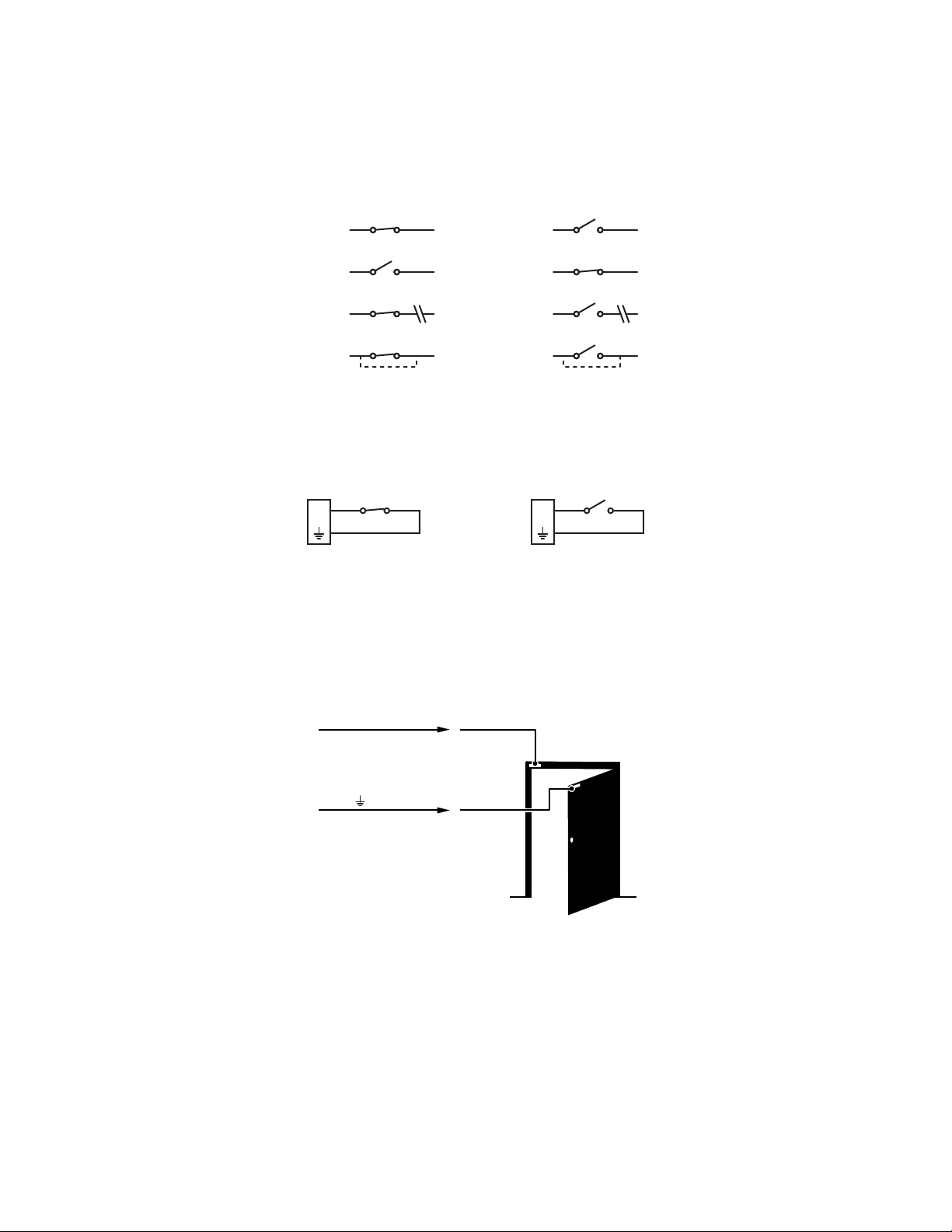
UNSUPERVISED ALARMS
+V
+V
+V
+V
+V
+V
+V
+V
BYPASS
CUT
BYPASS
CUT
GND
ALARM
GND
ALARM
GND
NO ALARM
GND
NO ALARM
GND
NO ALARM
GND
ALARM
GND
NO ALARM
GND
ALARM
NORMALLY OPENNORMALLY CLOSED
A1A1
NORMALLY OPENNORMALLY CLOSED
When an alarm is configured as an unsupervised alarm, an alarm is only activated when the normal alarm state (open or closed) changes.
Figure 12 illustrates the alarm and no alarm conditions of an unsupervised alarm input.
Figure 12. Unsupervised Alarm Conditions
Figure 13 illustrates the wiring configuration for unsupervised alarm inputs.
Figure 13. Normally Closed and Normally Open Unsupervised Alarm Input Wiring
NOTE: A normally closed alarm input can be defeated with a bypass; a normally open input can be defeated with a cut.
ALARM CONNECTIONS
Figure 14 shows how to wire the Sarix TI to an alarm.
ALARM A1
ALARM
Figure 14. Alarm Connections
18 C1317M-C (8/13)

CONNECTING AUDIO
NOTES:
• The maximum recommended cable length for the audio wiring is 304.8 m (1,000 ft).
• The Sarix TI is designed to work with microphones that have an internal preamplifier and provide professional line-level output (+4 dBu).
• If your microphone is a consumer line-level device (–10 dBu), the audio output may be quieter than you expect. Mic-level devices are not
recommended as they must be amplified to a line-level signal, which often results in excessive noise.
Figure 15. Line-In Audio Wiring
ì
Microphone
î
600-Ohm Impedance Matching Transformer
ï
UTP Wiring
ñ
0 V (zero volt) Return Wire
ó
+12 V Wire
C1317M-C (8/13) 19

IP Operation
DEVICE CONFIGURATION SEQUENCE
Once the device is installed and power is applied, the device undergoes a configuration sequence. The configuration sequence takes
approximately two minutes to complete, and then the device will come on line.
NOTE: If the device is not connected to a Dynamic Host Configuration Protocol (DHCP) server and DHCP is enabled, the configuration sequence
might take up to five minutes to complete.
MINIMUM SYSTEM REQUIREMENTS
Network interface card: 100 megabits (or greater)
Monitor: Minimum of 1024 x 768 resolution, 16- or 32-bit pixel color resolution
®
Web browser: Internet Explorer
analytics
Media player: Pelco Media Player or QuickTime
(or later)
NOTES:
• Pelco Media Player is recommended for control, smoothness, and reduced latency as compared to QuickTime.
• This product is not compatible with QuickTime version 7.6.4 for Windows XP or Windows Vista. If you have this version installed on your PC,
you will need to upgrade to QuickTime version 7.6.5.
• Network and processor bandwidth limitations might cause the video stream to pause or appear pixelated when additional Web-interface
users connect to the camera. Decrease the images per second (ips), resolution, compression, or bit rate settings of the Web interface video
streams to compensate for network or processor limitations.
8.0 (or later) or Mozilla® Firefox® 3.5 (or later); Internet Explorer 8.0 (or later) is recommended for configuring
®
7.6.5 for Windows XP, Windows Vista, and Windows 7; or QuickTime 7.6.4 for Mac OS X 10.4
ACCESSING THE IP CAMERA
The first time you access the camera, the live video page appears. By default, you are viewing the video as a public user and only have access to
the single stream live view.
If, for security purposes, users should not be allowed to view video without first logging on to the camera, change the permissions for public
users.
LOGGING ON TO THE CAMERA
1. Open the Web browser.
2. Type the camera’s IP address in the browser address bar.
NOTE: If you do not know the camera’s IP address, you can locate it using the Pelco Device Utility software.
3. Click the Login button in the navigation bar; a dialog box opens.
4. Type your user name and password.
NOTE: If you are logging on to the camera as the administrator for the first time, the default user name and password are admin
(all lowercase). For security purposes, be sure to change the password after you log on for the first time.
5. Click Log In.
20 C1317M-C (8/13)

LIVE VIDEO PAGE
The live video page allows you to manage the way you view live video and capture images. You can also view live video from this page and
access menus on the navigation bar (based on user permissions).
NOTE: The PTZ controls are viewable only after you have logged on to the device.
LIVE VIDEO PAGE ICONS
Viewable icons are based on user permissions.
Select Stream: Selects the viewable video stream that displays in live view (Primary, Secondary, QuickView, or Event) and selects
unicast or multicast and throttle settings.
Maximize Viewing Area: Scales the image to the full size of the browser. To resize the video pane to normal view, click the
Show Toolbar button in the upper-right corner of the window.
Show Toolbar: Returns the window to normal view. This icon is only available after the window has been set to maximize the
viewing area.
Open Stream in New Window: Opens the video in a scalable, independent window. Opening the video in a separate window allows
you to view the video while other applications are running. This window can be minimized, maximized, or closed using the title bar
buttons of the active window. The window can also be resized by dragging a corner of the window.
Take a Snapshot: Captures the image displayed in the video pane and saves it as a JPEG file.
Center Viewing Area*: Centers the camera on an area in the video pane. To center a viewing area, click the desired location in the
video pane.
Pan and Tilt*: Controls the pan and tilt functions. Click and drag the mouse to the left or right to pan the camera. Click and drag the
mouse up or down to tilt the camera.
Recalibrate Now: Immediately closes the shutter to improve video quality by removing noise from the image. During recalibration, the
video will freeze for approximately one-third of a second, and a small number of video frames will be lost.
Delay Recalibration: Delays closing the shutter by one minute.
C1317M-C (8/13) 21

PAN/TILT CONTROLS
NOTE: The PTZ controls are viewable only after you have logged on to the device.
Tilt Up: Click and hold the button to tilt the camera up.
Tilt Down: Click and hold the button to tilt the camera down.
Pan Left: Click and hold the button to pan the camera left.
Pan Right: Click and hold the button to pan the camera right.
Iris Open: Click and hold the button to open the iris and lighten the image.
Iris Close: Click and hold the button to close the iris and darken the image.
SELECTING A STREAM
1. Click the Select Stream button.
2. Select one of the following streams from the Select Stream page:
Primary Stream: To select this stream, click the button next to Primary Stream.
Secondary Stream: To select this stream, click the button next to Secondary Stream.
QuickView Stream: To select this stream, click the button next to QuickView Stream.
Event Stream: To select this stream, click the button next to Event Stream.
NOTE: If the secondary stream has not been configured, only Primary Stream, Event Stream, and QuickView Stream are available.
3. Configure the display settings for the selected stream. Available display settings are determined by the video compression of the selected
stream:
H.264 compression: For the Primary Stream or Secondary Stream. You can also select Unicast or Multicast from the Transmission dropdown menu.
JPEG compression: For the Secondary Stream or QuickView Stream, select Images Per Second (IPS) from the Throttle drop-down menu.
4. Click the Select button to save the stream settings.
Primary Stream and Secondary Stream
The Primary Stream and Secondary Stream are video streams that include compression, resolution, image rate, and bit rate settings. The streams
can be set up using a video configuration preset or they can be customized using the video configuration settings.
A video preset is a predefined video configuration that offers a good balance between video performance and bandwidth usage. For easy stream
configuration, use the Video Presets page located in the drop-down menu of the A/V Streams tab.
To customize the Primary Stream or Secondary Stream, select the Settings page and then use the Video Configuration page located in the dropdown menu of the A/V Streams tab. Configurable settings include the stream name, compression, resolution, image rate, bit rate, and I-frame
interval of the video streams. The default names for the streams are Primary Stream and Secondary Stream; however, if these stream names are
changed, the new names replace the default names (Primary Stream and Secondary Stream) on the Select Stream page.
QuickView Stream
The QuickView Stream is a predefined JPEG video stream with a lower resolution. This low resolution, low frame rate stream is available when
the Imaging tab settings are being configured. This allows users to view changes to exposure, white balance, and other settings as they are
configured and before the settings are saved.
22 C1317M-C (8/13)

The QuickView Stream is also ideal for users who are connected to a network with processor bandwidth limitations that might cause a high
resolution, high frame rate video stream to pause or appear pixilated.
The aspect ratio of the QuickView Stream mirrors that of the Primary Stream.
Event Stream
The Event Stream displays a list of alerts triggered by a running analytic behavior. The alert includes a screen capture, the profile that was
triggered, and the zone where the alert was detected. For the Event Stream to work you must have an analytic behavior profile running. To set up
and run analytic behaviors, profiles, and zones, use the Analytic Configuration page located in the drop-down menu of the Events tab.
Unicast
A unicast transmission sends a separate video stream to each user that is requesting data. Although multiple users might request the same data
from the camera at the same time, duplicate video streams are transmitted to each user. Every unicast user that connects to the camera
consumes additional processing power, which limits the number of simultaneous users who can access the camera.The camera supports a
maximum of 20 simultaneous users.
Multicast
A multicast transmission sends data to multiple users at the same time using one transmission stream. Each multicast user that connects to the
camera consumes no additional processing power; therefore, multicast video streams can be sent to an unlimited number of simultaneous users.
TAKING A SNAPSHOT
1. Click the Take a Snapshot button.
2. A dialog box opens, allowing you to open or save the file.
3. Select one of the following options:
Open: Your computer’s photo editing program opens and displays the screen image. This function is available only when using
Microsoft
Save: The image is saved as a JPEG file at the location you specify.
Cancel: The captured image is not opened or saved and the dialog box closes.
NOTE: If you are using JPEG, the captured image is the size of the largest MJPEG stream. If you are using MPEG-4 or H.264, the image is
captured using the QuickView Stream, which is a low resolution image.
SETTINGS PAGE
Depending on user permissions, the Settings page allows you to manage camera system and network settings, set up users, configure events,
and control the camera imaging and streams.
NOTE: The Settings menu might not be available if the user does not have permission to access this feature.
ACCESSING THE CAMERA MENUS
1. Log on to the camera.
2. Click the Settings link in the navigation bar located in the upper-right corner of the page; a list of menu tabs appears.
3. Place your mouse pointer over a tab to display a list of submenus.
®
Internet Explorer® 7.0 (or later) or Mozilla® Firefox® 3.0 (or later).
C1317M-C (8/13) 23

SYSTEM TAB
Use the System tab to change general system settings, configure the time settings, set up the text overlay for the live view, configure backup and
restore, display system information, and access snapshots generated by event handlers.
General System Settings
The general system settings page includes configurable fields for the device name, time settings, and text overlay settings. The device name is
the user-friendly description of the camera displayed in the gray area near the top of screen. The time server is an external server that uses
Network Time Protocol (NTP) to synchronize the camera date and time settings. The text overlay settings allow you to customize the appearance
of the video by displaying overlays such as the device name, or the date and time at the top or bottom of the video stream.
You can also use the general system settings page to turn the camera’s LEDs on or off and to configure the Simple Mail Transfer Protocol (SMTP)
server to send an email notification when an event handler is activated.
NOTE: Contact your network administrator for information on configuring email notification on your local network.
You can also use the general system settings page to generate a system log, reboot the camera, or restore the camera’s factory default settings.
Licensing Settings
The Licensing page provides an interface to add specialized features to your Sarix® device. Refer to license-specific documentation for more
information about installing licenses and the effects that a license might have on your device.
Backup and Restore Settings
The backup and restore settings page includes configurable fields for backup and restore of camera settings. Once the camera settings have
been configured for optimal scene display, use the backup feature to save the camera settings. If the camera settings are changed and
inadvertently result in a less desirable image, use the restore feature to restore the camera to the previously saved settings.
NOTE: This feature is not intended for the configuration of multiple units or for firmware upgrades.
Information Settings
The information settings page includes read-only fields for the firmware version, hardware version, model number, and serial number of the
camera. This information is typically required by Pelco Product Support for troubleshooting purposes.
Snapshot Viewer
The Snapshot Viewer page displays a list of snapshots saved to the SD card when a “Write JPEG to SD Card” event handler is activated. From
this page, you can open, download, or delete snapshots from the SD card. There are 100 snapshots displayed per page.
CHANGING THE DEVICE NAME
1. Place your mouse pointer over the System tab.
2. Select General Settings from the drop-down menu.
3. Click the Device Name box and highlight the text.
4. Type a user-friendly name into the Device Name box (2 to 63 characters). A user-friendly name makes it easier to recognize the device on
the network. Examples of user-friendly names are Front Door, Lobby, or Parking Lot.
5. Click Save to save the new device name, or click Reset to restore to the previously saved device name.
24 C1317M-C (8/13)

CONFIGURING DHCP TIME SERVER SETTINGS
The Auto setting allows the device to discover and synchronize with a network time server over IPv4 or IPv6. If a network time server is not
available for discovery on the network, select the Manual time server setting.
1. Place your mouse pointer over the System tab.
2. Select General Settings from the drop-down menu.
3. Select Auto for the Time Server.
4. Click the Save button to save the settings, or click the Reset button to clear all of the information you entered without saving it.
CONFIGURING MANUAL TIME SERVER SETTINGS
1. Place your mouse pointer over the System tab.
2. Select General Settings from the drop-down menu.
3. Select Manual for the Time Server.
4. Type the IP address or hostname of the time server in the Time Server box.
5. Configure the Time Zone by selecting the continent and region that are closest to the camera’s location from the Time Zone drop-down
menus.
NOTE: If your location observes a form of daylight saving time, the system automatically changes the time on the associated dates.
6. You can also specify time using an offset from Greenwich Mean Time (GMT) if you do not make a selection from the Time Zone drop-down
menu.
7. Click the Save button to save the settings, or click the Reset button to clear all of the information you entered without saving it.
CUSTOMIZING THE APPEARANCE OF THE TEXT OVERLAY
1. Place your mouse pointer over the System tab.
2. Select General Settings from the drop-down menu.
3. Set the Text Overlay settings:
Date/Time Overlay: Select Show to display the date and time in the live view overlay. The default setting is Hide.
Camera Name Overlay: Select Show to display the camera name in the live view overlay. The default setting is Hide.
Pan/Tilt Overlay: Select Show to display the pan, tilt, and direction position when moving the camera in the live view overlay. The default
setting is Hide.
4. Select the display position for the overlay from the Position drop-down menu. Selections include Top Right, Top Center, Top Left, Bottom
Right, Bottom Center, and Bottom Left.
5. If an overlay is set to Show, view the format of the overlay in the Overlay Format area.
6. Click the Save button to save the settings, or click the Reset button to clear all of the information you entered without saving it.
GENERATING A SYSTEM LOG
1. Place your mouse pointer over the System tab.
2. Select General Settings from the drop-down menu.
3. Click the Generate System Log button.
4. A dialog box opens, allowing you to open or save the file.
5. Save the file to create a system log that can be used by Pelco Product Support for troubleshooting. Contact Pelco Product Support at
1-800-289-9100 (USA and Canada) or +1-559-292-1981 (international).
C1317M-C (8/13) 25
Loading...