

Page 1
Installation and Assembly - Glass Electronic Tower
IMPORTANT! Read entire instruction sheet before you start installation and assembly.
Before you start make sure all parts listed are included with your product.
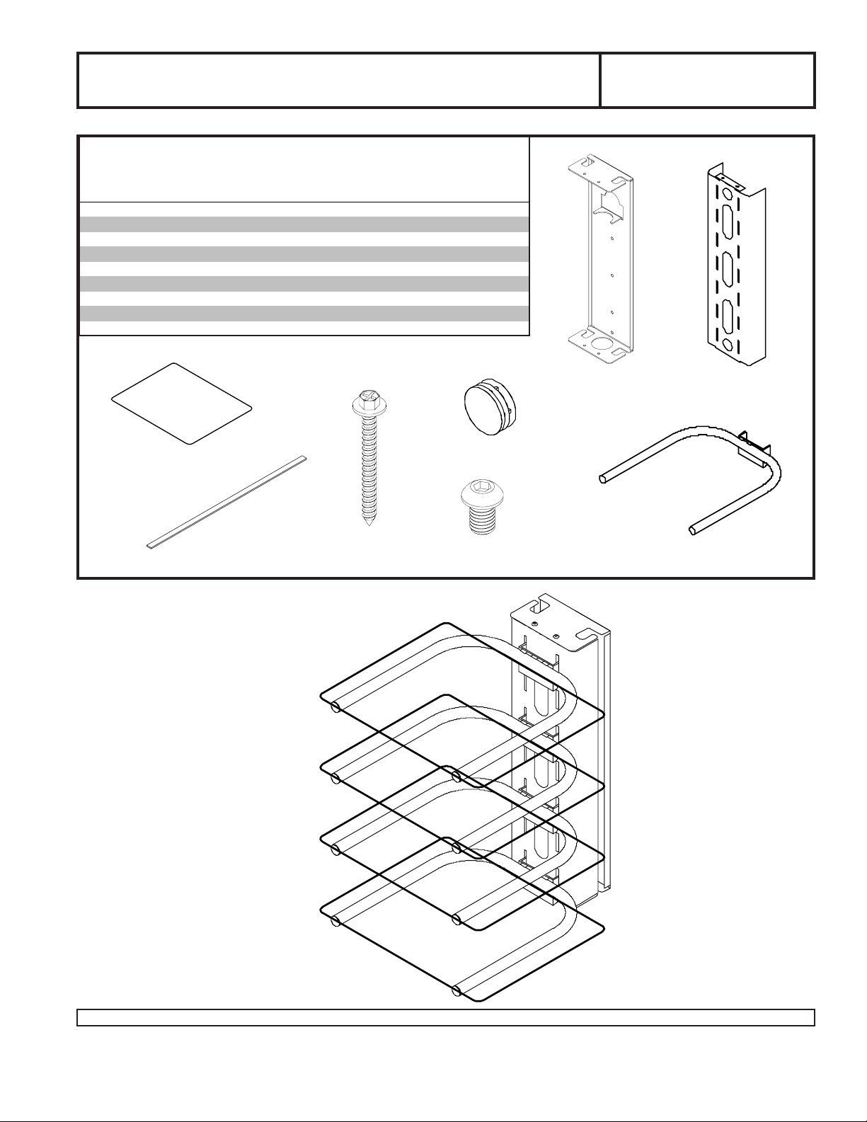
Parts List
Description Qty Part # Part # Part #
wall bracket 1 021-1035 021-4035 021-2035
A
shelf bracket 1 021-1027 021-4027 021-2027
B
equipment support 4 021-1031 021-4031 021-2031
C
#14 x 2.5" wood screw 5 5S1-015-C03 5S1-015-C03 5S1-015-C04
D
1/4-20 x 3/8" s ock et head s crew 4 520-2015 520-2015 520-2028
E
VCR foam 8 599-3802 599-3802 599-3802
F
endcap 8 590-1077 590-1077 590-2072
G
5/32" allen wrench (not shown) 1 560-9706 560-9706 560-9706
H
glass 4 590-0098 590-0098 590-0098
I
PM 610G PM 610SG PM 610W G
A
Models: PM 610G, PM 610SG,
PM 610WG
B
F
I
G
C
D
Wall Entertainment Center
E
1 of 5
Visit the Peerless Web Site at www.peerlessindustries.com For customer service call 1-800-729-0307 or 708-865-8870.
ISSUED: 07-16-01 SHEET #: 021-9007-4 09-10-07
Page 2
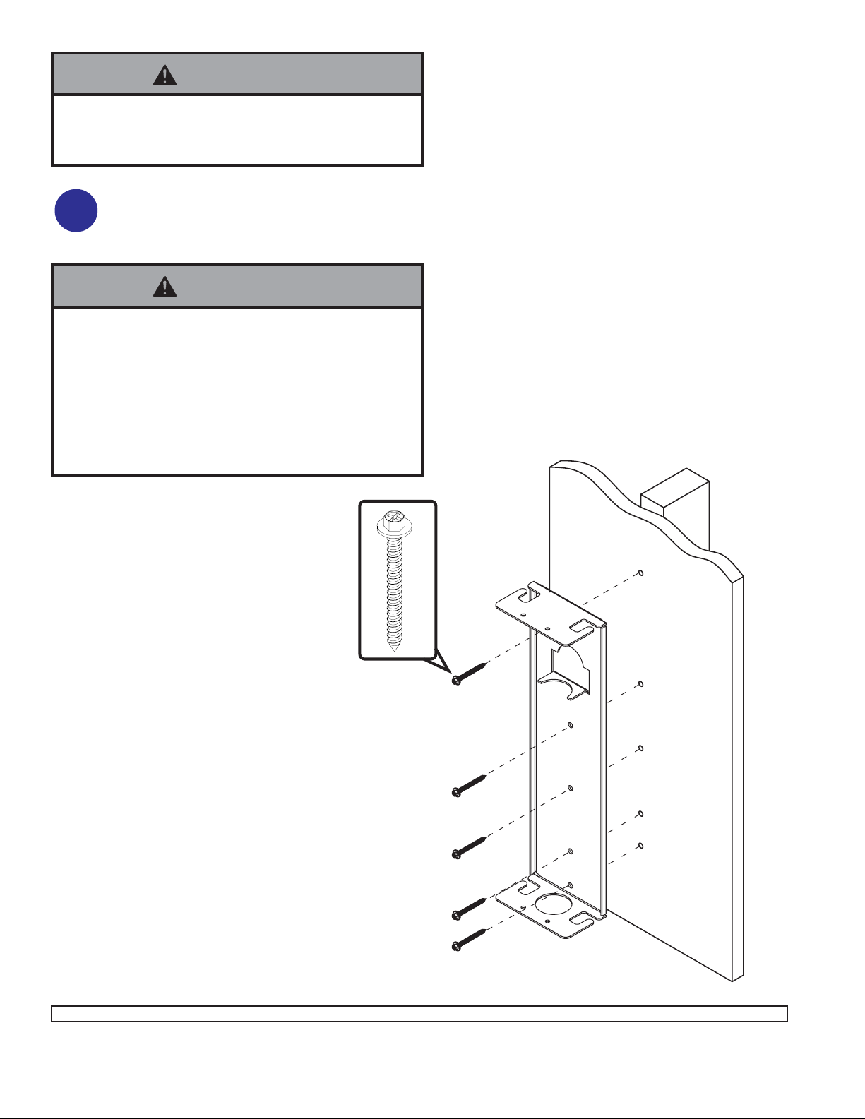
WARNING
• Installer must verify that the wall will safely support
four times the combined weight of all attached equipment and hardware.
For Wood Stud Walls drill five 5/32" (4 mm) dia. holes
to a minimum depth of 2.5" (64 mm) into stud center.
1
Attach wall bracket (A) using #14 x 2.5" (6 mm x 65
mm) wood screws (D).
WARNING
• Tighten wood screws so that wall plate is firmly
attached, but do not overtighten. Overtightening can
damage the screws, greatly reducing their holding
power.
• Never tighten in excess of 80 in • lb (9 N.M.).
• Make sure that mounting screws are anchored into the
center of the studs. The use of an "edge to edge" stud
finder is highly recommended.
D
A
2 of 5
Visit the Peerless Web Site at www.peerlessindustries.com For customer service call 1-800-729-0307 or 708-865-8870.
ISSUED: 07-16-01 SHEET #: 021-9007-4 09-10-07
Page 3

WARNING
• When installing Peerless wall mounts on cinder block, verify that you have a minimum of 1-3/8" of actual concrete
surface in the hole to be used for the concrete anchors. Do not drill into mortar joints! Be sure to mount in a solid
part of the block, generally 1" minimum from the side of the block. Cinder block must meet ASTM C-90 specifications. It is suggested that a standard electric drill on slow setting is used to drill the hole instead of a hammer drill
to avoid breaking out the back of the hole when entering a void or cavity.
• Concrete must be 2000 psi density minimum. Lighter density concrete may not hold concrete anchor.
• Make sure that the wall will safely support four times the combined load of the equipment and all attached hardware and components.
NOTE: Fastners for concrete not included, order
two accessory kits #ACC205. For Concrete Walls
2
drill five 5/16" (8 mm) dia. holes to a minimum depth
of 1 3/4" (45 mm). Attach wall bracket (A) using
concrete expansion anchors as shown.
concrete
anchor
FOR PRODUCT SAFETY, USE ONLY... RAWLTM #5005
OR HILTI
Order TWO #ACC205 accessory kits. Each contains three
.312 x 1.625 (8 mm x 41 mm) concrete expansion anchors.
TM
HL814 CONCRETE ANCHORS.
WARNING
• Tighten concrete anchor bolts firmly, but do not
overtighten. Overtightening can damage the bolts,
greatly reducing their holding power.
• Never tighten in excess of 80 in • lb (9 N.M.).
WARNING
• Always attach concrete expansion anchors directly to
load-bearing concrete.
• Never attach concrete expansion anchors to concrete
covered with plaster, drywall or other finishing material.
A
A
Insert and hammer in anchor.
Tighten to 80 in • lb (9 N.M.) maximum torque. The
anchor will expand and grip inside the hole.
3 of 5
Visit the Peerless Web Site at www.peerlessindustries.com For customer service call 1-800-729-0307 or 708-865-8870.
ISSUED: 07-16-01 SHEET #: 021-9007-4 09-10-07
Page 4

Attach shelf bracket (B) to wall
bracket (A) with four screws (E)
3
using allen wrench.
A
E
B
Snap eight end caps (G) into four equipment
supports (C). Attach four equipment supports
4
(C) to shelf bracket (B).
For additional
accessory kit ACC102.
equipment supports
order
B
C
G
G
4 of 5
Visit the Peerless Web Site at www.peerlessindustries.com For customer service call 1-800-729-0307 or 708-865-8870.
ISSUED: 07-16-01 SHEET #: 021-9007-4 09-10-07
Page 5

Attach eight strips of adhesive foam (F)
to tops of four equipment supports (C).
5
C
F
C
Place a glass plate (I) on top of each
equipment support (C).
6
I
5 of 5
Visit the Peerless Web Site at www.peerlessindustries.com For customer service call 1-800-729-0307 or 708-865-8870.
© 2004 Peerless Industries, Inc. All rights reserved.
Peerless is a registered trademark of Peerless Industries, Inc.
All other brand and product names are trademarks or registered trademarks of their respective owners.
ISSUED: 07-16-01 SHEET #: 021-9007-4 09-10-07
 Loading...