

Installation and Assembly:
PRG Precision Gear Projector Mount with Universal
Adapter Plate
Models: PRG-UNV, PRG-UNV-S, PRG-UNV-W
Features:
• ImageLockTM alignment prevents picture sag or
drift
• Exclusive aluminum track quick release
2300 White Oak Circle • Aurora, Il 60502 • (800) 865-2112 • Fax: (800) 359-6500 • www.peerlessmounts.com
Max UL Load Capacity:
ISSUED: 09-30-09 SHEET #: 056-9024-5 07-18-11
50 lb (22.7 kg)
NOTE: Read entire instruction sheet before you start installation and assembly.
WARNING
• Do not begin to install your Peerless product until you have read and understood the instructions
and warnings contained in this Installation Sheet. If you have any questions regarding any of the
instructions or warnings, for US customers please call Peerless customer care at
1-800-865-2112, for all international customers, please contact your local distributor.
• This product should only be installed by someone of good mechanical aptitude, has experience
with basic building construction, and fully understands these instructions.
• Make sure that the supporting surface will safely support the combined load of the equipment and
all attached hardware and components.
• Never exceed the Maximum UL Load Capacity. See page one.
• If mounting to wood joists ceilings, make sure that mounting screws are anchored into the center
of the studs. Use of an "edge to edge" stud fi nder is highly recommended.
• Always use an assistant or mechanical lifting equipment to safely lift and position equipment.
• Tighten screws fi rmly, but do not overtighten. Overtightening can damage the items, greatly
reducing their holding power.
• This product is intended for indoor use only. Use of this product outdoors could lead to product
failure and personal injury.
• This product was designed to be installed on the following wall construction only;
WALL CONSTRUCTION HARDWARE REQUIRED
• Wood Stud Included
• Wood Joist Included
• Solid Concrete Included
• Brick Contact Qualifi ed Professional (Not Evaluated By UL)
• Other or unsure? Contact Qualifi ed Professional
Tools Needed for Assembly
• stud fi nder ("edge to edge" stud fi nder is recommended)
• phillips screwdriver
• drill
• 5/16" bit for solid concrete surface
• 5/32" bit for wood studs
• open end wrench
• level
Table of Contents
Parts List................................................................................................................................................3
Projector Mount Assembly Installation................................................................................................4-7
Attaching Adapter Plate to Projector......................................................................................................9
Accessories ...................................................................................................................................15, 16
2 of 51
ISSUED: 09-30-09 SHEET #: 056-9024-5 07-18-11
PRG-UNV PRG-UNV-S PRG-UNV-W
Description Qty. Part # Part # Part #
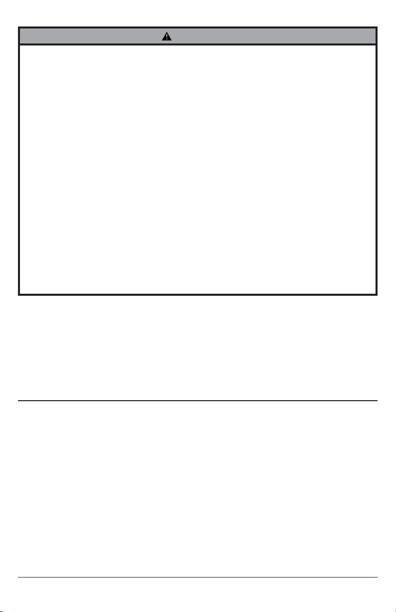
A projector mount assembly 1 054-1171 054-4171 054-2171
B adapter plate 1 055-1938 055-4938 055-2838
C concrete anchor 2 590-0320 590-0320 590-0320
D #14 x 2-1/2" phillips hex head wood screw 2 5S1-015-C03 5S1-015-C04 5S1-015-C04
E #10-32 x 1/4" socket pin screw 1 520-1196 520-2196 520-2196
F 1/4" flat washer 2 540-1078 540-1078 540-1078
G #6 flat washer x 1/2" OD 4 540-1025 540-2025 540-2025
H 2 mm security allen wrench 2 560-1097 560-1097 560-1097
I 4 mm security allen wrench 1 560-9646 560-9646 560-9646
J M3 x 8 mm serrated washer head socket pin screw 4 510-1004 510-2004 510-2004
K M4 x 10 mm serrated washer head socket pin screw 4 510-1060 510-2060 510-2060
L M5 x 10 mm serrated washer head socket pin screw 4 510-1126 510-2063 510-2063
M M6 x 10 mm serrated washer head socket pin screw 4 510-1066 510-2066 510-2066
Parts List
Before you start check the parts list to insure all of the parts shown are included.
NOTE: Actual parts may appear slightly different than illustrated.
A
B
CD
I
E
J
F
K
G
L
3 of 51
H
M
ISSUED: 09-30-09 SHEET #: 056-9024-5 07-18-11
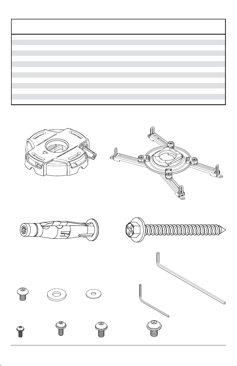
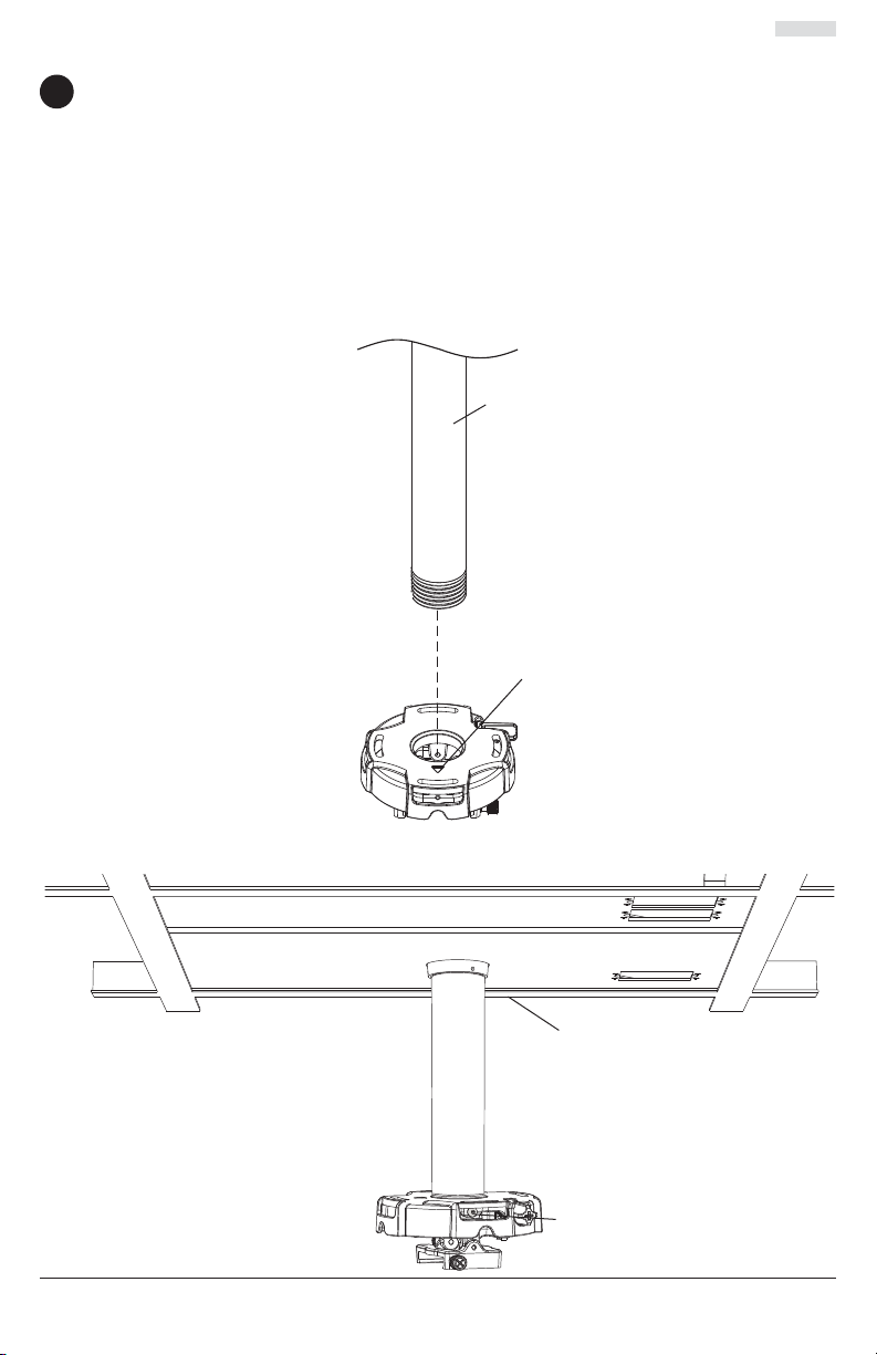
Installation to Extension Column/Ceiling Plate
NOTE: Refer to accompanying instructions with ceiling plates (sold separately) for installing
1
these models to ceiling.
Screw projector mount assembly (A) onto extension column as shown in fi gure 1.1.
Tighten swivel stop screw against extension column, fl ush mount tube or reducer using 4mm
security allen wrench (I) as shown in fi gure 1.2.
NOTE: Swivel stop screw is used to jam against threads of extension column, fl ush mount tube
or reducer to prevent any excess movement of projector mount assembly (A). Do not overtighten
screw; overtightening screw will damage threads making it diffi cult to separate products.
Skip to step 5.
1-1/2" EXTENSION COLUMN
(SOLD SEPARATELY)
(UL LISTED EXT OR AEC SERIES)
ARROW INDICATES
FRONT OF MOUNT
A
fi g. 1.1
fi g. 1.2
4 of 51
CMJ 455
(SOLD SEPARATELY)
SWIVEL STOP SCREW
ISSUED: 09-30-09 SHEET #: 056-9024-5 07-18-11
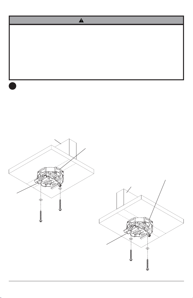
Installation to Wood Joist Ceilings
WARNING
• Installer must verify that the supporting surface will safely support the combined load of the
equipment and all attached hardware and components.
• Tighten wood screws so that wall plate is fi rmly attached, but do not overtighten. Overtightening
can damage the screws, greatly reducing their holding power.
• Never tighten in excess of 80 in. • lb (9 N.M.).
• Make sure that mounting screws are anchored into the center of the stud. The use of an "edge to
edge" stud fi nder is highly recommended.
• Hardware provided is for attachment of mount through standard thickness drywall or plaster into
wood studs. Installers are responsible to provide hardware for other types of mounting situations
(not evaluated ny UL).
Place projector mount assembly (A) on ceiling as a template and mark the center of the two
2
mounting holes. Make sure that the mounting holes are in the center of the wood joist. Drill two
5/32" (4mm) dia. holes to a minimum depth of 2-1/2" (64mm). Attach projector mount assembly
(A) with two #14 x 2-1/2" (6mm x 64mm) wood screws (D) and two fl at washers (F) as shown in
fi gure 2.1 or fi gure 2.2 depending on joist orientation.
Tighten wood screws (D) using 3/8" (10mm) socket wrench or phillips screwdriver until projector
mount assembly (A) is fi rmly attached.
Skip to step 5.
fi g. 2.1
A
WOOD JOIST
F
D
ACCESS SLOT FOR
OPEN END WRENCH
ALLOWS TIGHTENING
OF WOOD SCREW (D).
fi g. 2.2
A
ACCESS SLOT FOR
OPEN END WRENCH
ALLOWS TIGHTENING
OF WOOD SCREW (D).
WOOD JOIST
F
D
5 of 51
ISSUED: 09-30-09 SHEET #: 056-9024-5 07-18-11
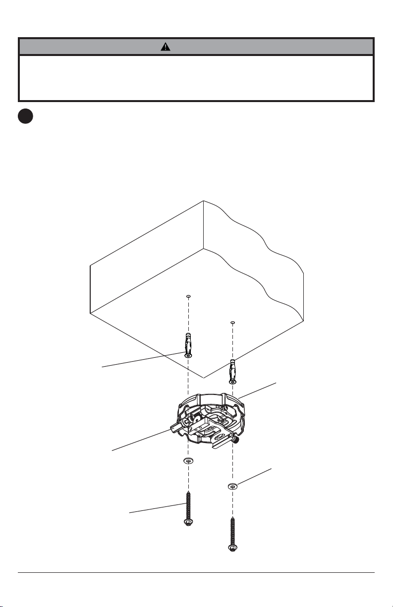
Installation to Concrete Ceilings
WARNING
• Concrete must be 2000 psi density minimum. Lighter density concrete may not hold concrete
anchor.
• Make sure that the wall will safely support four times the combined load of the equipment and all
attached hardware and components.
Place projector mount assembly (A) on ceiling as a template and mark the center of the two
3
mounting holes. Drill two 5/16" (8mm) dia. holes to a minimum depth of 2-1/2" (64mm).
Attach projector mount assembly (A) using two concrete anchors (C), two fl at washers (F),
and two #14 x 2-1/2" wood screws (D) as shown. NOTE: Mounting slots on projector mount
assembly allow for 30° (±15°) of rotation before fully securing wood screw. Tighten wood screws
(D) using 3/8" (10mm) socket wrench, phillips screwdriver or 10mm open end wrench until
projector mount assembly (A) is fi rmly attached.
Skip to step 5.
CONCRETE CEILING
C
ARROW ON TOP OF
PROJECTOR MOUNT
ASSEMBLY INDICATES
FRONT OF MOUNT
A
F
D
6 of 51
ISSUED: 09-30-09 SHEET #: 056-9024-5 07-18-11
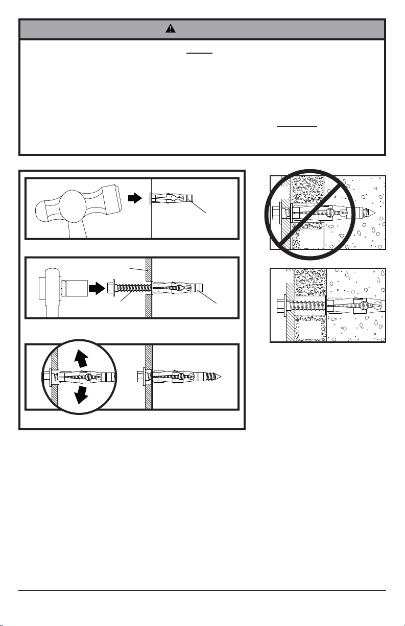
WARNING
• Always attach concrete expansion anchors directly to load-bearing concrete.
• Never attach concrete expansion anchors to concrete covered with plaster, drywall, or
other fi nishing material. If mounting to concrete surfaces covered with a fi nishing surface is
unavoidable (not evaluated ny UL), the fi nishing surface must be counterbored as shown below.
Be sure concrete anchors do not pull away from concrete when tightening screws. If plaster/
drywall is thicker than 5/8" (16mm), custom fasteners must be supplied by installer (not evaluated
by UL).
• Tighten screws so that projector mount is fi rmly attached, but do not overtighten. Overtightening
can damage screws, greatly reducing their holding power.
• Never tighten in excess of 80 in. • lb (9 N.M.).
INCORRECT
1
Drill holes and insert anchors (C).
concrete
surface
C
A
plaster/
dry wall
concrete
2
A
D
Place plate (A) over anchors (C) and secure with
screws (D).
3
Tighten all fasteners.
CORRECT
A
concrete
CUTAWAY VIEW
C
plaster/
dry wall
7 of 51
ISSUED: 09-30-09 SHEET #: 056-9024-5 07-18-11
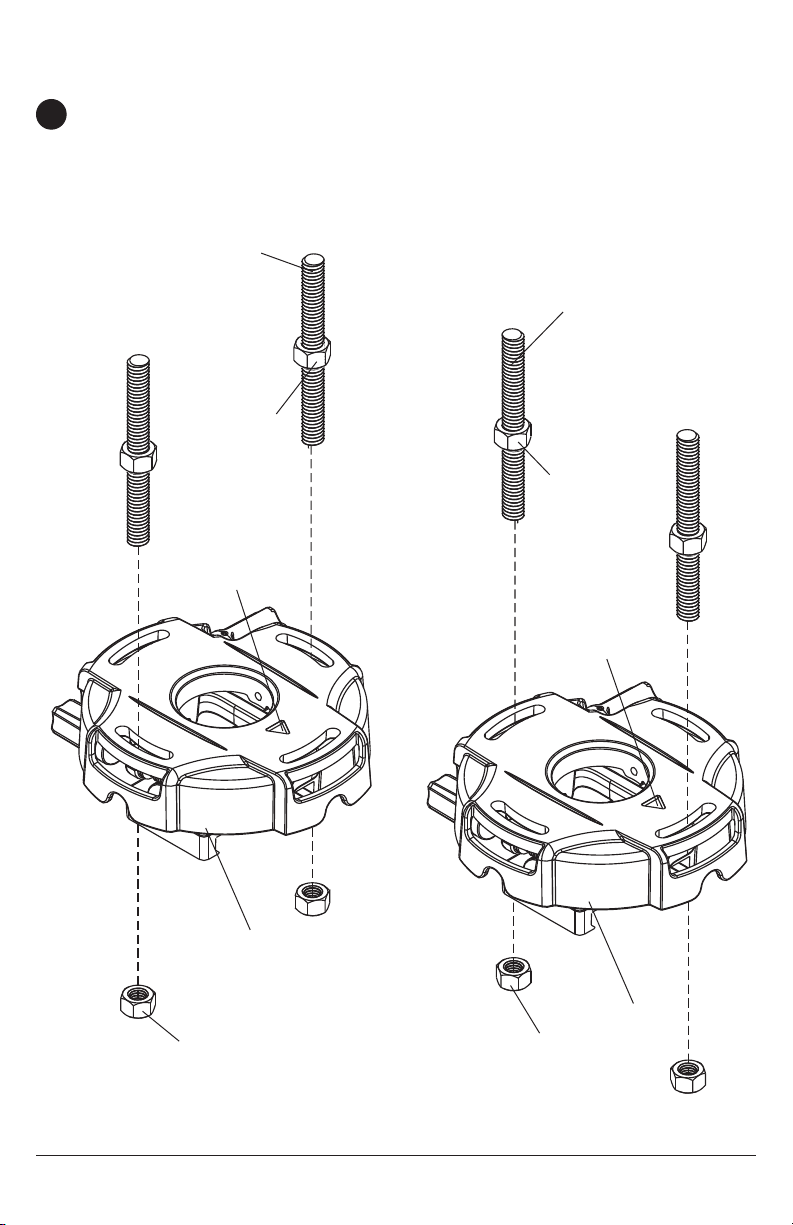
Installation to Threaded Rod
(Not evaluated by UL - Professional installation only)
Thread two 1/4-20 hex thin nylon-insert locknuts (not included) on two 1/4-20 threaded rods (not
4
included) to the desired height of projector mount assembly. Attach projector mount assembly
(A) to the two 1/4-20 threaded rods using two 1/4-20 hex thin nylon-insert locknuts as shown in
fi gure 4.1 or fi gure 4.2.
1/4-20 THREADED
ROD (NOT
INCLUDED)
1/4-20 HEX THIN
NYLON-INSERT
LOCKNUT (NOT
INCLUDED)
ARROW
INDICATES
FRONT OF
MOUNT
fi g. 4.1
fi g. 4.2
1/4-20
THREADED
ROD (NOT
INCLUDED)
1/4-20 HEX
THIN NYLONINSERT
LOCKNUT
(NOT
INCLUDED)
ARROW
INDICATES
FRONT OF
MOUNT
A
1/4-20 HEX THIN
NYLON-INSERT
LOCKNUT (NOT
INCLUDED)
8 of 51
A
1/4-20 HEX
THIN NYLONINSERT
LOCKNUT (NOT
INCLUDED)
ISSUED: 09-30-09 SHEET #: 056-9024-5 07-18-11
Attaching Adapter Plate to Projector
NOTE: The projector you are installing may differ in appearance from the sample illustrated
5
below.
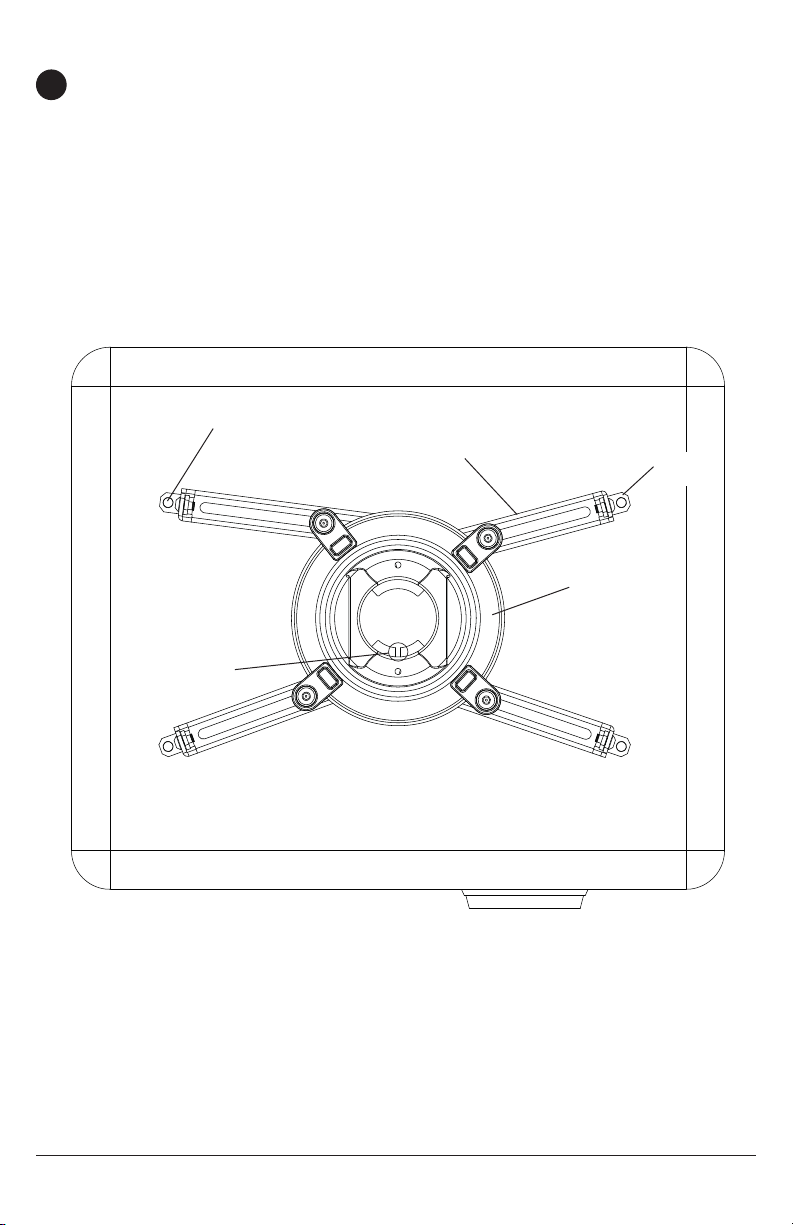
Place projector upside down. Locate adapter plate (B) with notch facing forward as close to
projector center of gravity as possible without covering any mounting holes. Loosen channels
with 4mm security allen wrench (I), and if there are only three mounting holes remove fourth
channel. Using one channel for each mounting hole, position feet of channels over mounting
holes as shown below. IMPORTANT: If projector does not have at least three mounting holes,
do not use this adapter plate.
NOTE: Some projectors have feet which can be removed and the corresponding threaded insert
can be used for a mounting hole.
NOTE: Once channels are in position retighten fasteners.
*Notch indicates front of projector.
MOUNTING HOLE
CHANNEL
B
FOOT OF
CHANNEL
*
GENERIC PROJECTOR
9 of 51
ISSUED: 09-30-09 SHEET #: 056-9024-5 07-18-11
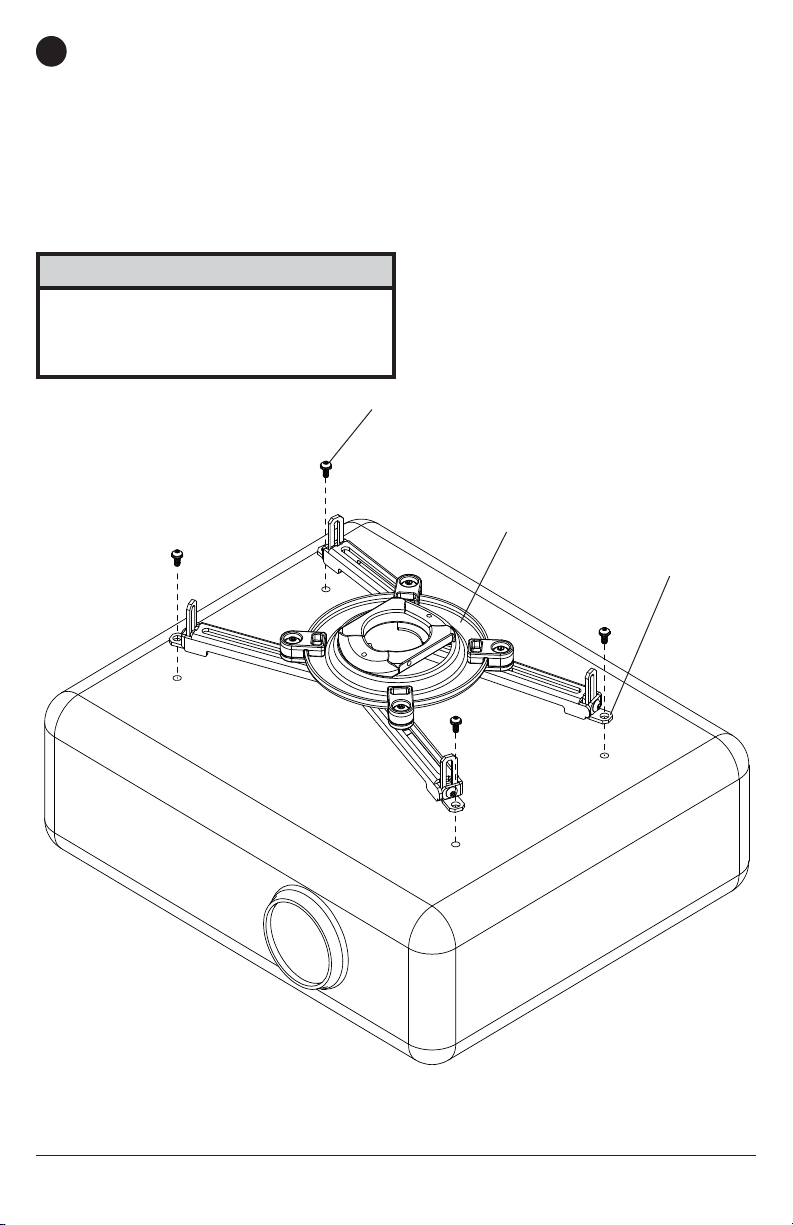
Attach adapter plate (B) to projector using one screw (J, K, L or M) for each channel as shown
6
below. Tighten all screws, while keeping the center of gravity. Be sure that adapter plate (B) is
straight. Adjust the feet of the channels to keep the adapter plate level. Tighten all screws with
4mm security allen wrench (I) while keeping the center of gravity. If M3 screws (J) are used,
tighten using 2mm security allen wrench (H).
NOTE: Projectors will require different size screws for mounting. Use a combination of screws
(J, K, L or M) and foot adjustment that will result in channels of adapter plate (B) fi tting tightly
against projector. IMPORTANT: In order to properly engage the threads in the mounting holes,
the screw must be turned at least 3 full turns.
NOTE: If using screw (J), place washer (G) between screw (J) and foot of channel.
CAUTION
• It is the responsibility of the installer to ensure
that the projector is properly ventilated. Feet
of channels are used to raise the mount off the
projector surface.
J, K, L or M
B
FOOT OF
CHANNEL
10 of 51
ISSUED: 09-30-09 SHEET #: 056-9024-5 07-18-11
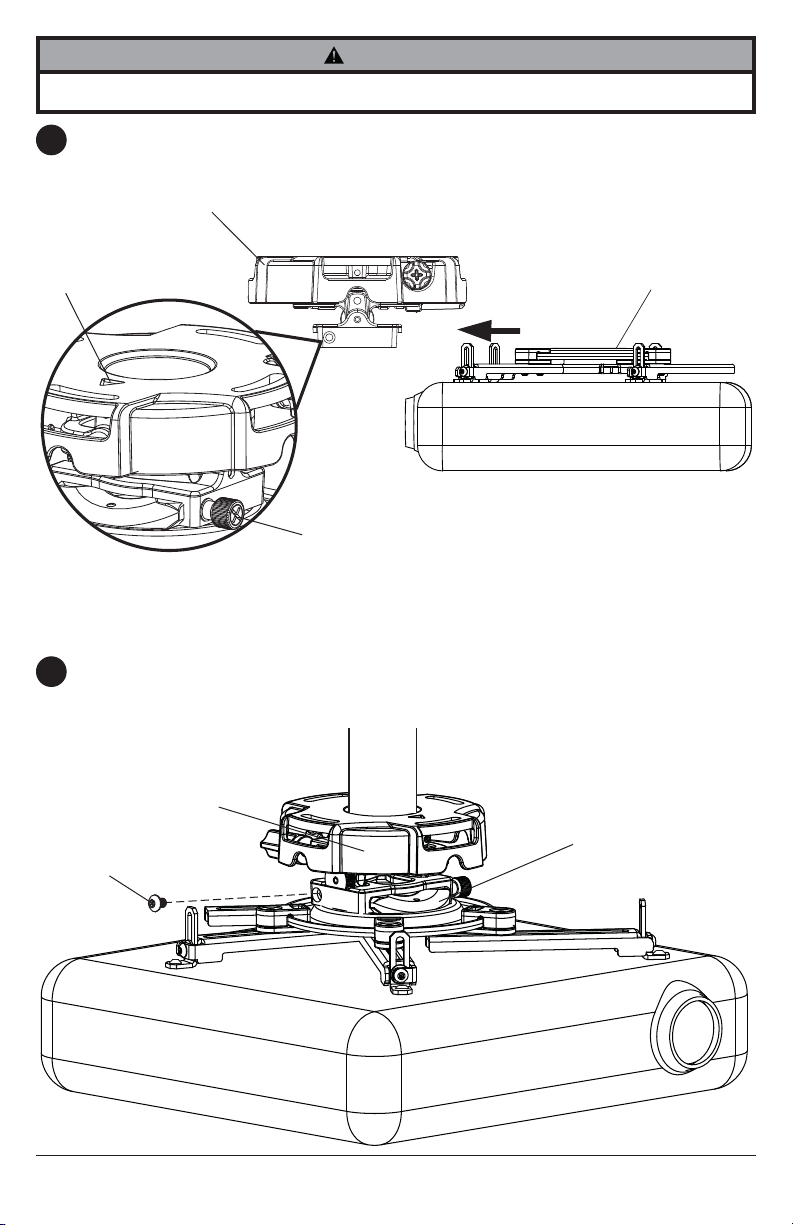
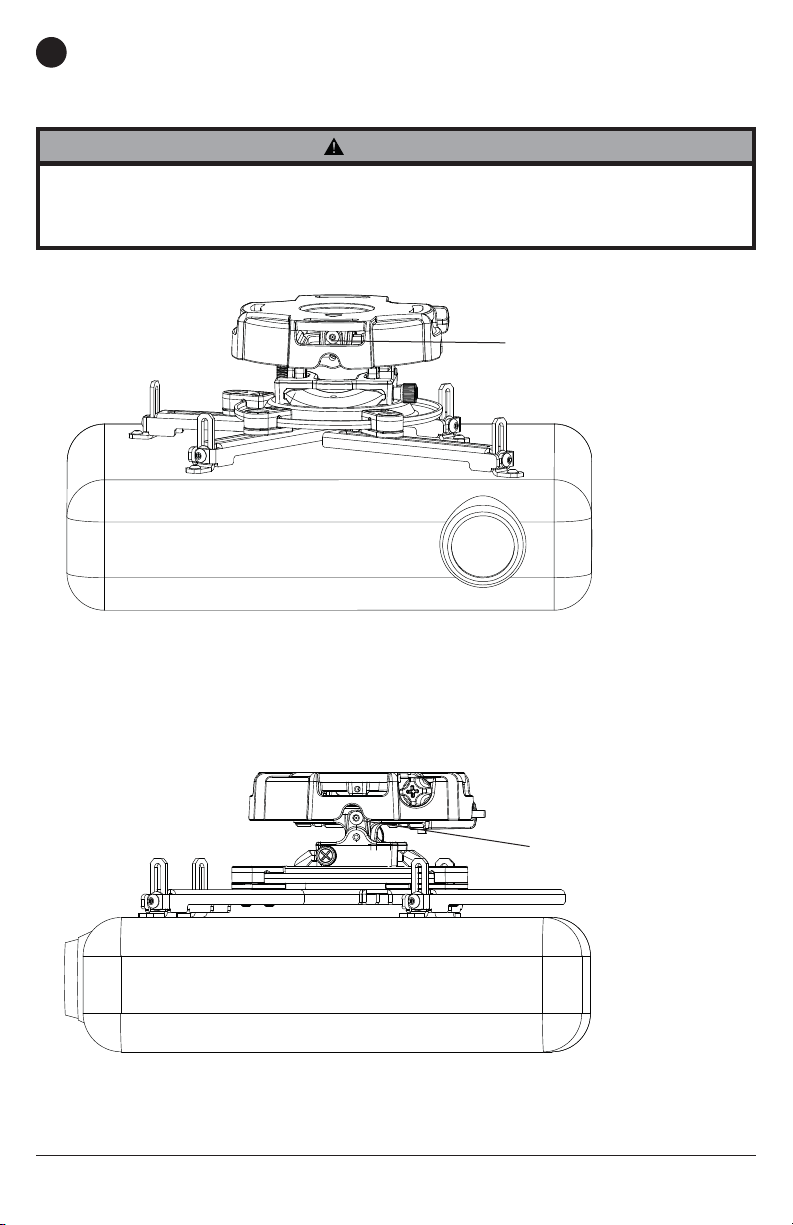
WARNING
• Always use an assistant or mechanical lifting equipment to safely lift and position the projector.
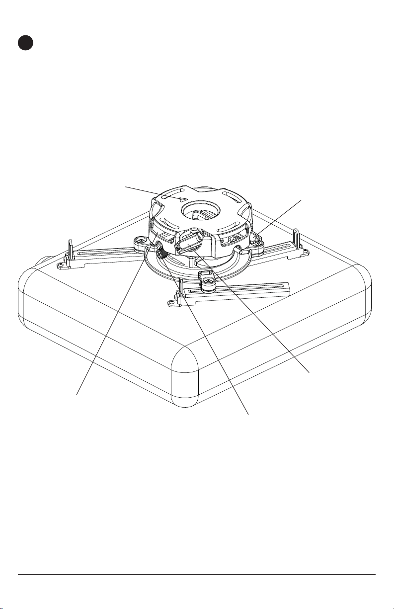
Slide connection block with projector into projector mount assembly (A) as shown. Push in and
7
tighten captive screw to secure projector to projector mount assembly (A).
FRONT OF MOUNT
ARROW INDICATES
FRONT OF MOUNT
CAPTIVE SCREW
IMPORTANT: For security installations, insert one #10-32 x 1/4" socket pin screw (E) through
8
projector mount assembly (A) and into connection block as shown. Tighten screw with 4mm
security allen wrench (I).
A
CONNECTION BLOCK
A
CONNECTION
BLOCK
E
11 of 51
ISSUED: 09-30-09 SHEET #: 056-9024-5 07-18-11
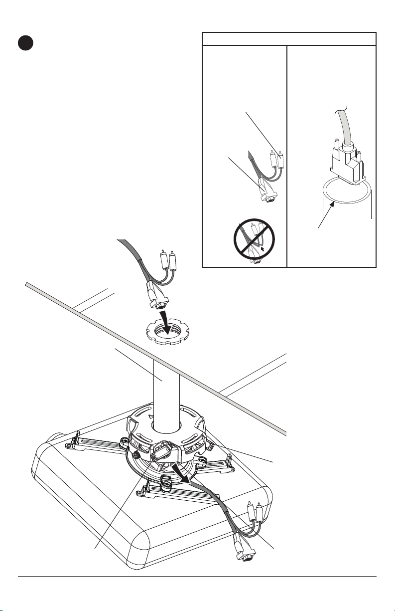
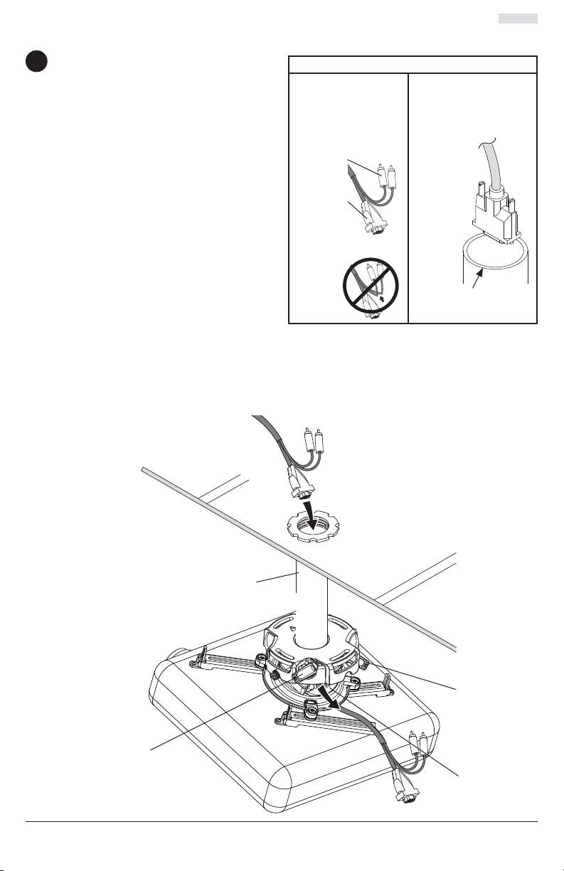
Cable Management
To make an opening to route cables through
9
projector mount assembly, adjust projector
mount assembly to full upward tilt position
by turning knob for tilt adjustment as shown
in fi gure 9.2. Left or right roll position can be
adjusted if more space is required.
NOTE: Be certain tamper resistant
screws are not engaged before making
adjustments (see step 11).
Route cables through top of extension
column as shown in fi gure 9.1 and fi gure
9.2.
NOTE: A method for assisting cables
through extension column may be required
(example: string tied to connector to help
pull through extension column).
Route cables through projector mount
assembly as shown in fi gure 9.2 and
connect to projector.
fi g. 9.2
fi g. 9.1
CABLES WITH
COMBINATION OF VGA
CONNECTOR
AND RCA PLUGS
BEND WIRES OF RCA
PLUGS IN OPPOSITE
DIRECTION
ROUTE
CONNECTOR
THROUGH
FIRST
DO NOT CRIMP
WIRES
NOTE: INNER
DIAMETER OF
EXTENSION COLUMN
MAY NOT ALLOW
PASSAGE FOR ALL
CONNECTOR TYPES.
CABLE
CONNECTOR
INNER DIAMETER
OF EXTENSION
COLUMN
EXTENSION
COLUMN
KNOB FOR TILT
ADJUSTMENT
12 of 51
KNOB FOR ROLL
ADJUSTMENT
OPENING FOR
ROUTING CABLES
ISSUED: 09-30-09 SHEET #: 056-9024-5 07-18-11
Projector Alignment
To adjust yaw (swivel) for threaded rod mounting applications: Loosen locknuts for
10
threaded rods (step 4) until projector mount can be rotated. Rotate mount to desired position
and retighten locknuts.
To adjust yaw (swivel) for extension column applications: Loosen screw on projector mount
assembly (A) indicated below until projector mount can be rotated. Rotate mount to desired
position and retighten screw.
To adjust pitch (forward and backward tilt): Turn knob on back of mount as shown below.
Pull knob out and turn by hand for easy adjustment or insert #2 phillips screwdriver in end of
knob and turn.
To adjust roll (side to side tilt): Turn knob on side of mount as shown below. Pull knob out and
turn by hand for easy adjustment or insert #2 phillips screwdriver in end of knob and turn.
ARROW INDICATES FRONT OF
MOUNT
ACCESS SLOT FOR
OPEN END WRENCH
ALLOWS TIGHTENING
OF LOCKNUTS WITHOUT
REMOVING PROJECTOR
A
KNOB FOR PITCH
ADJUSTMENT
KNOB FOR ROLL
ADJUSTMENT
SCREW FOR YAW (SWIVEL) STOP
(REFER TO STEP 1, FIG. 1.2)
13 of 51
ISSUED: 09-30-09 SHEET #: 056-9024-5 07-18-11
To prevent tampering with the pitch and roll adjustments: Tighten the two tamper resistant
11
security screws on the projector mount assembly using 4mm security allen wrench (I) to lock the
pitch and roll adjustments as shown below.
NOTE: Tighten screws fi rmly, but do not overtighten. Overtightening can damage the mount.
WARNING
• Do not adjust pitch or roll while tamper resistant security screws are fully engaged.
• Loosen the two tamper resistant security screws one complete turn before adjusting the projector
mount assembly or damage may occur.
TO LOCK ROLL, TIGHTEN
TAMPER RESISTANT SECURITY
SCREW
FRONT VIEW
SIDE VIEW
14 of 51
TO LOCK PITCH, TIGHTEN
TAMPER RESISTANT
SECURITY SCREW
ISSUED: 09-30-09 SHEET #: 056-9024-5 07-18-11
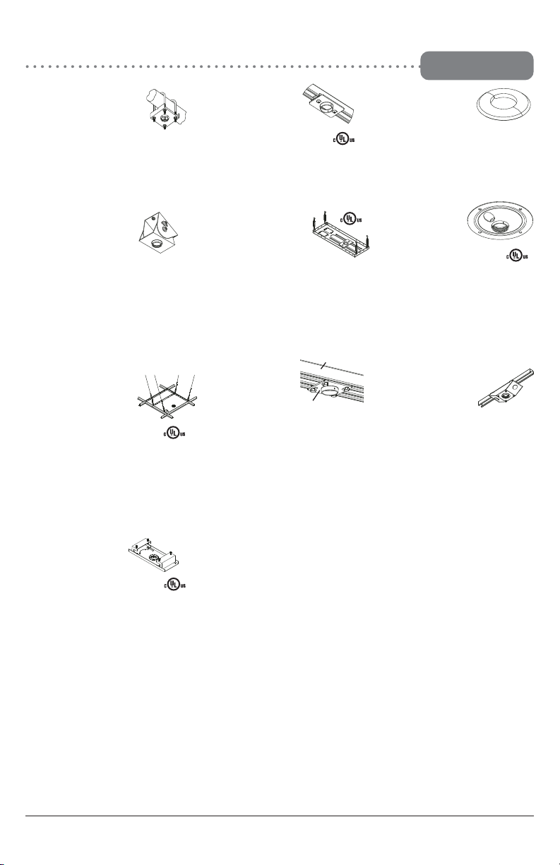
PRG Series Projector Mount Accessories
I-Beam Clamps
M
ODELS
:
ACC 558, ACC 559
M
AX LOAD
:
250 lbs. (113.4 kg.)
C
OLOR
:
Black
• ACC 558 clamps onto 4"-8" I-Beam
• ACC 559 clamps onto 7"-12" I-Beam
Unistrut® Adapter
M
ODEL
: ACC 550
M
AX LOAD
:
250 lbs. (113.4 kg.)
C
OLOR
:
Black
• Designed for use with
1 5/8" x 1 5/8" 12 gauge Unistrut
Accessory Pack for CMJ 455
M
ODEL
: ACC 455*
This pack includes 4 hanger brackets and
4 hanger clamps for additional stability. For
use with model CMJ 455.
M
ODEL
: ACC 557*
M
AX LOAD
:
250 lbs. (113.4 kg.)
C
OLOR
:
Black
• Attaches to a square, round,
rectangular, or I-Beam truss up to 3" in
diameter
Escutcheon Ring
M
ODEL
: ACC 640
• Covers hole where extension
column passes through ceiling
• Hinged ring wraps around extension column
• Included with CMJ 500
Lightweight Cathedral
Ceiling Plate
M
ODEL
: ACC 912*
M
AX LOAD
:
60 lbs. (27.2 kg.)
C
OLOR
:
Black
• Designed specifically for projectors
• Allows a projector to be mounted
on an angled ceiling
New!
Lightweight Adjustable
Suspended Ceiling Kit
M
ODEL
: CMJ 500
M
AX LOAD
:
60 lbs. (27.2 kg.)
C
OLOR
:
White
• Mounts above 2’ x 4’ or 2’ x 2’ false
ceiling tile
• Includes tie wire supports, flush mount
tube, and offers two knockout panels
for outlet boxes
• Offers unlimited adjustment for
projector placement
New!
Lightweight Suspended Ceiling Kit
M
ODEL
: CMJ 455
M
AX LOAD
:
50 lbs. (22.7 kg.)
C
OLOR
:
White
• Five different projector
mount attachment points
• Includes tie wire supports,
flush mount tube, and
offers two knockout panels
for outlet boxes
• May either replace a 2’ x 2’ false
ceiling tile or mount above an existing
2’ x 2’ or 2’ x 4’ ceiling tile
Anti-Vibration Ceiling Plates
M
ODELS
:
ACC 840*, ACC 845*
M
AX LOAD
:
60 lbs. (27.2 kg.)
C
OLOR
:
Black
• ACC 840 was designed for
a structural ceiling (wood only)
• ACC 845 was designed for
a Unistrut ceiling (1 5/8" x 1 5/8"
12 gauge Unistrut)
• Reduces unwanted vibrations
that may cause internal damage
to the equipment and/or cause the
screen image to vibrate
• Features two cord management
access holes
• Patent pending
Unistrut or Structural
Ceiling Plates
M
ODELS
:
CMJ 300*, CMJ 310*
M
AX LOAD
:
250 lbs. (113.4 kg.)
C
OLOR
:
Black
• CMJ 300 is a 4" x 4" ceiling plate
• CMJ 310 is a 8" x 8" ceiling plate
• Designed for a Unistrut ceiling
(1 5/8" x 1 5/8" 12 gauge Unistrut)
or a solid structural ceiling
(mounting hardware not included)
Unistrut
Ceiling plate
R
Ceiling Plates
R
*
= Not UL Listed
Round Ceiling Plate
M
ODEL
:
ACC570(S)(W)
C
OLOR
:
Black, silver or white
MAX L
OAD
:
150 lb (68 kg)
S
HIP WEIGHT
:
1.7 lb (.8 kg)
• Designed for finished or
structural ceilings (wood or
concrete)
• Features a cord management
R
R
R
15 of 51
ISSUED: 09-30-09 SHEET #: 056-9024-5 07-18-11
PRG Series Projector Mount Accessories
ALLIGATOR
®
Concrete Anchors
M
ODELS
: ACC 203, 204
• ACC 203 contains 3 anchors
• ACC 204 contains 4 anchors
• Used for attachment to
concrete, concrete block,
or brick
• Used in conjunction with wood
screws (supplied with
projector mount and/or
ceiling plate)
• Expands in length and binds to
the contours of the hole and
the screw
Cord Wrap
M
ODELS
: ACC 852(W)(S)*
C
OLOR
:
Black, White, or Silver
M
ODEL
: ACC 830*
C
OLOR
:
Black
• Provides 4" of radial
adjustment side to side
• Includes Flush Mount
Tube, EXT 002
TM
Plus Security Cables
M
ODEL
: ACC 021*
• With 1/4" security cable and fasteners
• Includes adhesive for non-fastener applica
tions
M
ODEL
: ACC 020*
• With security lock
• For use with projectors that have a built-in
security slot
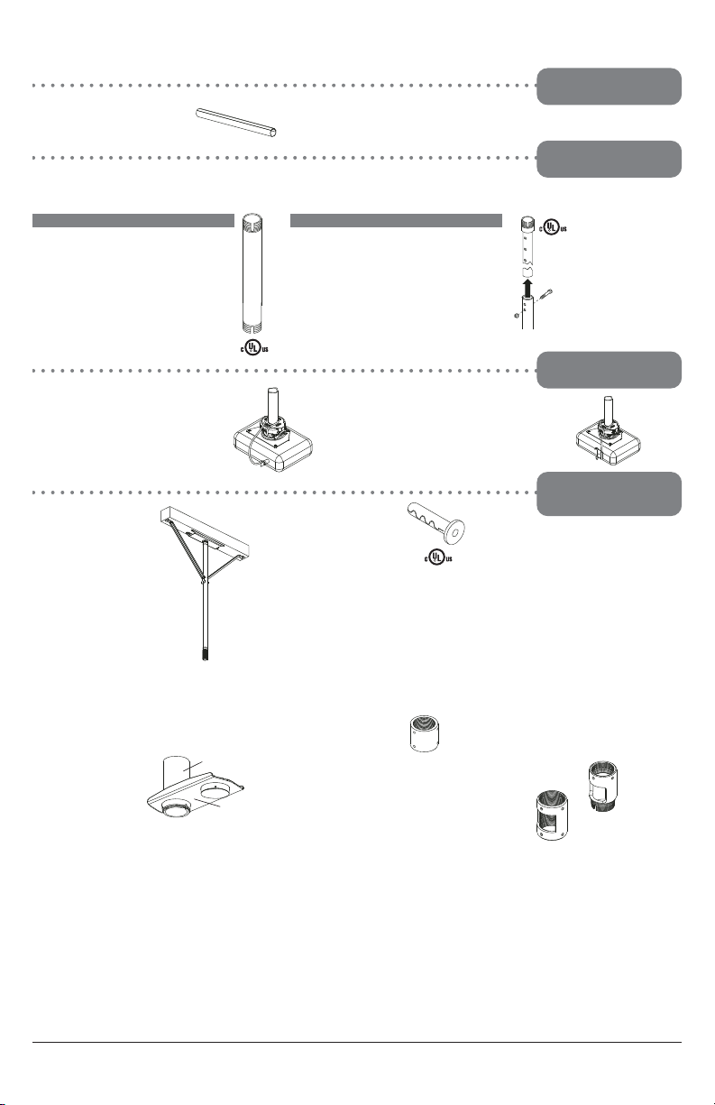
Extension
column
Extension Columns
Security Accessories
Additional Projector
Mount Accessories
Cord Management
Fixed Length 1 1/2"
Extension Columns
C
OLOR
:
Black
R
= Not UL Listed
• Includes, four, 2' sections
• Designed to externally route cords along the
outside of an 1/2" extension column
• Sections can be stacked to create longer lengths
or cut to desired length
M
ODEL
: ACC 050*
C
OLOR
:
Black
• Can be used to reduce
unwanted swaying that may
occur with extension
column installations
• Includes a hose clamp, two
stabilizer column supports,
& hardware for mounting to
wood joists
• For use with extension
columns over 21"
MODEL Drop Le ngth Ship Weight
EXT 006 8"
(20 cm)
2.5 lbs
(1.13 kg)
EXT 018 20"
(51 cm)
5 lbs
(2.27 kg)
EXT 101 14"
(36 cm)
3.5 lbs
(1.59 kg)
EXT 102 26"
(66 cm)
6 lbs
(2.72 kg)
EXT 103 38"
(97 cm)
9.25 lbs
(4.2 kg)
EXT 104 50"
(127cm)
12 lbs
(5.44 kg)
EXT 105 62"
(158 cm)
14.75 lbs
(6.69 kg)
EXT 106 74"
(188 cm)
18 lbs
(8.16 kg)
EXT 107 86"
(219 cm)
20.75 lbs
(9.41 kg)
EXT 108 98"
(249 cm)
23.25 lbs
(10.55 kg)
EXT 109 110"
(279 cm)
26.5 lbs
(12.02 kg)
EXT 110 122"
(310 cm)
29 lbs
(13.15 kg)
Side to side
adjuster
Extension Column
Connector
M
ODEL
: ACC 109*
C
OLOR
:
Black
• Can be used to join two
1-1/2" extension columns to
create a maximum length
of 20’
• Secures to columns with
Armor Lock
TM
Security
screws
Extension Column Connector
with Cord Management
M
ODEL
: ACC800, ACC850(S)
C
OLOR
: ACC800
Black
ACC850
Black or Silver
• 1-1/2" access hole for internal cord
management
• Unit has 1-1/2"-11.5 NPT fitting for
attachment of extension column
• Security screws included
• ACC800: One male and one female
connection to provide internal cord
management between extension
column and mount or ceiling plate
• ACC850: Two female connectors to
join two extension columns to
create maximum length of 20’
ACC850
ACC800
Adjustable Length 1 1/2"
Extension Columns
C
OLOR
:
Black
MODEL Drop Length Ship Weight
ADJ 006009 8"-11" 4 lbs.
ADJ 012018 14"-20" 4.75 lbs.
ADJ 018024 20"-26" 6.25 lbs.
ADJ 0203 26"-38" 8 lbs.
ADJ 0305 38"-62" 13.5 lbs.
ADJ 0406 50"-74" 16.25 lbs.
ADJ 0507 62"-86" 18.5 lbs.
ADJ 0608 74"-98" 21.75 lbs.
ADJ 0709 86"-110" 24.5 lbs.
ADJ 0810 98"-122" 27 lbs.
ADJ 0911 110"-134" 29 lbs.
ADJ 1012 122"-146" 31 lbs.
R
16 of 51
(1.81 kg)
(2.15 kg)
(2.83 kg)
(3.63 kg)
(6.12 kg)
(8.39 kg)
(11.11 kg)
(12.25 kg)
(13.15 kg)
(14.06 kg)
(7.37 kg)
(9.87 kg)
R
ISSUED: 09-30-09 SHEET #: 056-9024-5 07-18-11

Instrucciones para la instalación y el ensamblaje:
Soporte para proyectores PRG Precision Gear con
placa adaptadora universal
Modelos: PRG-UNV, PRG-UNV-S, PRG-UNV-W
Características:
• El alineamiento ImageLockTM evita que haya
descenso o desvío de la imagen.
• Destrabe rápido del tornillo imperdible que
fi ja el bloque de conexión al exclusivo riel de
aluminio.
2300 White Oak Circle • Aurora, Il 60502 • (800) 865-2112 • Fax: (800) 359-6500 • www.peerlessmounts.com
Capacidad máxima de soportar carga:
50 lb (22.7 kg)
PUBLICADO: 09-30-09 HOJA #: 056-9024-5 07-18-11

NOTA: Lea toda la hoja de instrucciones antes de iniciar la instalación y el montaje.
Español
ADVERTENCIA
• No comience a instalar su producto de Peerless hasta haber leído y entendido las instrucciones
y las advertencias contenidas en la Hoja de Instalación. Si tiene alguna pregunta acerca de cualquiera de las instrucciones o las advertencias, por favor, llame a Servicio al Cliente de Peerless
al 1-800-865-2112 si está en EE. UU. Si es un cliente internacional, por favor, comuníquese con
su distribuidor local.
• Este producto sólo debe ser instalado por una persona que tenga una buena aptitud mecánica,
que tenga experiencia en construcción básica de edifi cios y que entienda estas instrucciones en
su totalidad.
• Asegúrese de que la superfi cie de apoyo sostendrá, con seguridad, la carga combinada del
equipo y todos los fi jadores y componentes.
• Nunca sobrepase la capacidad máxima de soportar carga Underwriters Laboratories.
página 17.
• Si va a instalar el producto en una pared con montantes de madera, asegúrese de que los
tornillos de montaje estén anclados en el centro de los montantes. Se recomienda utilizar un
localizador de montantes de "borde a borde".
• Siempre cuente con la ayuda de un asistente o utilice un equipo mecánico de izar para levantar
y colocar el equipo con más seguridad.
• Apriete los tornillos con fi rmeza, pero no en exceso. Apretarlos en exceso puede dañar los
artículos y puede disminuir signifi cativamente su fuerza de fi jación.
• Este producto está diseñado para uso en interiores solamente. Utilizar este producto en exteriores podría causar fallas del producto y lesiones a individuos.
• Este producto fue diseñado para ser instalado en paredes con la siguiente construcción solamente:
CONSTRUCCIÓN DE LA PARED ACCESORIOS NECESARIOS
• Montante de madera Incluido
• Viga de madera Incluido
• Concreto macizo Incluido
• Ladrillo Comuníquese con un profesional califi cado
(No evaluados por UL)
• ¿Otra superfi cie o no está seguro? Comuníquese con un profesional califi cado
Vea la
Herramientas necesarias para el ensamblaje
• localizador de montantes (se recomienda uno de “borde a borde”)
• destornillador phillips
• taladro
• broca de 5/16" para superfi cies de concreto
• broca de 5/32" para montantes de madera
• llave plana o tipo Crescent
• nivel
Tabla de contenido
Lista de piezas.....................................................................................................................................19
Instalación unidad del soporte para proyectores ............................................................................20-23
Fijar la placa adaptadora al proyector ................................................................................................. 25
Accesorios .....................................................................................................................................31, 32
18 de 51 PUBLICADO: 09-30-09 HOJA #: 056-9024-5 07-18-11

Antes de comenzar, coteje la lista de piezas para asegurarse de que se han incluido todas las piezas.
PRG-UNV PRG-UNV-S PRG-UNV-W
Descripción Cant.
N.
o
de pieza N.o de pieza N.o de pieza
A unidad del soporte para proyectores 1 054-1171 054-4171 054-2171
B placa adaptadora 1 055-1938 055-4938 055-2838
C anclaje para concreto 2 590-0320 590-0320 590-0320
D
tornillos de cabeza hexa
g
.
o
14 x 2-1/2"
2 5S1-015-C03 5S1-015-C04 5S1-015-C04
E
6
6
6
Lista de piezas
E
tornillo pasador de cabeza hueca N.
10x-32x1/4
1
520 1196
520 2196
520 2196
p
.
o
6 x 1/2" OD
4 540-1025 540-2025 540-2025
H llave allen de seguridad de 2 mm 2 560-1097 560-1097 560-1097
I llave allen de seguridad de 4 mm 1 560-9646 560-9646 560-9646
J
tornillo pasador de cabeza hueca con arandela dentada de
M3 x 8 mm
4 510-1004 510-2004 510-2004
K
tornillo pasador de cabeza hueca con arandela dentada de
M4 x 10 mm
4 510-1060 510-2060 510-2060
L
tornillo pasador de cabeza hueca con arandela dentada de
M5 x 10 mm
4 510-1126 510-2063 510-2063
M
tornillo pasador de cabeza hueca con arandela dentada de
M6 x 10 mm
4 510-1066 510-2066 510-2066
Español
onalpara madera N
o
-
F arandela plana de 1/4" 2 540-1078 540-1078 540-1078
G
arandela
lana N
”
1 520-119
520-219
520-219
NOTA: Las piezas pueden verse un poco distintas a la ilustración.
A
B
CD
I
E
J
F
K
G
L
19 de 51 PUBLICADO: 09-30-09 HOJA #: 056-9024-5 07-18-11
H
M

Instalación en columnas de extensión / placas de techo
NOTA: Lea las instrucciones de las placas de techo (que se venden por separado) para ver
1
cómo instalar estos modelos en los techos.
Fije la unidad del soporte para proyectores (A) a la columna de extensión utilizando los tornillos,
como se muestra en la fi gura 1.1. Apriete el tornillo de tope, que impide el giro, a la columna de
extensión, al tubo de montaje empotrado o al reductor utilizando la llave allen de seguridad de
4mm (I), como se muestra en la fi gura 1.2.
NOTA: El tornillo de tope, que impide el giro, se utiliza para que trabe contra las columnas de
extensión, el tubo de montaje empotrado o el reductor para evitar que la unidad del soporte para
proyectores (A) se mueva más de lo necesario. No apriete el tornillo en exceso; apretarlo en
exceso dañará las roscas y hará que sea difícil separar las piezas.
Pase al paso 5.
COLUMNA DE EXTENSIÓN DE 1 1/2"
(SE VENDE POR SEPARADO)
(CLASIFICACIÓN DE UL EXT O SERIE AEC)
Español
fi g. 1.2
fi g. 1.1
A
LA FLECHA INDICA LA
PARTE DELANTERA DEL
SOPORTE
CMJ 455
(SE VENDE POR SEPARADO)
TORNILLO DE
TOPE QUE
IMPIDE EL GIRO
20 de 51 PUBLICADO: 09-30-09 HOJA #: 056-9024-5 07-18-11

Instalación en techos con vigas de madera
ADVERTENCIA
• El instalador tiene que asegurarse de que la superfi cie de apoyo sostendrá, con seguridad, la
carga combinada del equipo y todos los fi jadores y componentes.
• Apriete los tornillos para madera de manera que la unidad del soporte para proyectores se
fi je fi rmemente, pero no en exceso. Apretarlos en exceso puede dañar los tornillos y puede
disminuir signifi cativamente su fuerza de sujeción.
• Nunca apriete a más de 80 pulg-lb (9 N•m).
• Asegúrese de que los tornillos de montaje estén anclados en el centro del montante. Se
recomienda utilizar un localizador de montantes de “borde a borde”.
• Los accesorios para la instalación que se proveen son para fi jar el soporte a montantes de
madera a través de tabique de yeso-cartón o yeso de espesor estándar. Los instaladores son
responsables de suministrar los accesorios necesarios para otros tipos de instalaciones (no
evaluados por UL).
Coloque la unidad del soporte para proyectores (A) contra el techo a manera de plantilla y
2
marque el centro de los dos agujeros de montaje. Asegúrese de que los agujeros de montaje
estén en el centro de la viga de madera. Taladre dos agujeros de 5/32" (4mm) de diámetro a
una profundidad mínima de 2-1/2" (64mm). Fije la unidad del soporte para proyectores (A) con
dos tornillos para madera de 14 x 2-1/2" (6mm x 64mm) (D) y dos arandelas planas (F), como
se muestra en la fi gura 2.1 o en la fi gura 2.2, dependiendo de la orientación de la viga.
Apriete los tornillos para madera (D) utilizando una llave de copa de 3/8" (10mm), un
destornillador phillips o una llave plana o tipo Crescent de 10mm hasta que la unidad del
soporte para proyectores (A) se fi je fi rmemente.
Pase al paso 5.
Español
VIGA DE MADERA
A
F
D
fi g. 2.1
LA RANURA DE ACCESO
PARA LA LLAVE PLANA O
TIPO CRESCENT PERMITE
APRETAR EL TORNILLO
PARA MADERA (D)
A
21 de 51 PUBLICADO: 09-30-09 HOJA #: 056-9024-5 07-18-11
VIGA DE
MADERA
fi g. 2.2
LA FLECHA EN LA
PARTE SUPERIOR
DE LA UNIDAD DEL
SOPORTE PARA
PROYECTORES
INDICA LA PARTE
DELANTERA DEL
SOPORTE
F
D

Instalación en techos de concreto
ADVERTENCIA
• El concreto tiene que tener una densidad mínima de 2,000 psi. Es posible que un concreto de
menos densidad no sostenga el anclaje para concreto.
• Asegúrese de que la superfi cie de apoyo sostendrá, con seguridad, la carga combinada del
equipo y todos los fi jadores y componentes.
Coloque la unidad del soporte para proyectores (A) contra el techo a manera de plantilla
3
y marque el centro de los dos agujeros de montaje. Taladre dos agujeros de 5/16" (8mm)
de diámetro a una profundidad mínima de 2-1/2" (64mm). Fije la unidad del soporte para
proyectores (A) utilizando dos anclajes para concreto (C), dos arandelas planas (F) y dos
tornillos para madera de 14 x 2-1/2" (D), como se muestra. NOTA: Las ranuras de montaje de la
unidad del soporte para proyectores permiten una rotación de 30° (±15°) antes de fi jar el tornillo
para madera completamente. Apriete los tornillos para madera (D) utilizando una llave de copa
de 3/8" (10mm), un destornillador phillips o una llave plana o tipo Crescent de 10mm hasta que
la unidad del soporte para proyectores (A) se fi je fi rmemente.
Pase al paso 5.
TECHO DE
CONCRETO
Español
C
LA FLECHA INDICA LA
PARTE DELANTERA
DEL SOPORTE
A
F
D
22 de 51 PUBLICADO: 09-30-09 HOJA #: 056-9024-5 07-18-11

Español
ADVERTENCIA
• Siempre fi je los anclajes para concreto directamente en la pared que sostiene la carga.
• Nunca fi je los anclajes para concreto a una pared de concreto recubierta con yeso, tabique de
yeso-cartón u otro material de acabado. Si es inevitable hacer la instalación en una superfi cie
de concreto recubierta con una superfi cie de acabado (no evaluado por UL) , la superfi cie de
acabado tiene que ser escariada, como se muestra abajo. Asegúrese de que los anclajes para
concreto no se separen del concreto cuando apriete los tornillos. Si el grosor de la capa de
yeso o tabique de yeso-cartón tiene un grosor mayor de 5/8" (16mm), el instalador tiene que
suministrar las fi jaciones especiales (no evaluado por UL).
• Apriete los tornillos para madera con fi rmeza, pero no en exceso. Apretarlos en exceso puede
dañar los tornillos y puede disminuir signifi cativamente su fuerza de fi jación.
• Nunca apriete a más de 80 pulg-lb (9 N•m).
INCORRECTO
1
concrete
surface
A
C
concreto
Taladre los agujeros e inserte los anclajes (C).
2
Coloque la placa (A) sobre los anclajes (C) y fíjela con los
tornillos (D).
A
D
C
3
Apriete todas las fi jaciones.
yeso / tabique de
yeso-cartón
A
VISTA EN CORTE
yeso / tabique de
yeso-cartón
CORRECTO
concreto
23 de 51 PUBLICADO: 09-30-09 HOJA #: 056-9024-5 07-18-11

Instalación en varillas roscadas
(No evaluado por UL – Instalación profesional solamente)
Pase dos contratuercas hexagonales delgadas de nilón de 1/4-20 (no incluidas) por dos varillas
4
roscadas de 1/4-20 (no incluidas) a la altura que quiere instalar la unidad del soporte para
proyectores. Fije la unidad del soporte para proyectores (A) a las dos varillas roscadas de
1/4-20 utilizando las dos contratuercas hexagonales delgadas de nilón de 1/4-20, como se
muestra en la fi gura 4.1 o en la fi gura 4.2.
VARILLA ROSCADA DE
1/4-20 (NO INCLUIDA)
VARILLA ROSCADA DE
CONTRATUERCA
HEXAGONAL
DELGADA
DE NILÓN DE
1/4-20
(NO INCLUIDA)
LA FLECHA
INDICA LA
PAR TE
DELANTERA
DEL SOPORTE
fi g. 4.1
fi g. 4.2
1/4-20 (NO INCLUIDA)
CONTRATUERCA
HEXAGONAL
DELGADA
DE NILÓN DE
1/4-20
(NO INCLUIDA)
LA FLECHA
INDICA LA
PAR TE
DELANTERA
DEL SOPORTE
Español
A
CONTRATUERCA
HEXAGONAL
DELGADA DE
NILÓN DE 1/4-20
(NO INCLUIDA)
A
CONTRATUERCA
HEXAGONAL
DELGADA DE
NILÓN DE 1/4-20
(NO INCLUIDA)
24 de 51 PUBLICADO: 09-30-09 HOJA #: 056-9024-5 07-18-11

Fijar la placa adaptadora al proyector
NOTA: El proyector que usted va a instalar puede tener una apariencia distinta al que se
5
muestra en la ilustración de abajo.
Coloque el proyector al revés. Coloque la placa adaptadora (B) de manera que la muesca
quede hacia el frente y tan cerca del centro de gravedad del proyector como sea posible sin
obstruir los agujeros de montaje. Afl oje los rieles con una llave allen de seguridad de 4mm (I)
y, si el proyector sólo tiene tres agujeros de montaje, quite el cuarto riel. Utilizando un riel para
cada agujero de montaje, coloque las patas de los rieles sobre los agujeros de montaje como se
muestra abajo.
IMPORTANTE: Si el proyector no tiene, por lo menos, tres agujeros de montaje, no utilice esta
placa adaptadora.
NOTA: Algunos proyectores tienen patas que se pueden quitar y entonces el inserto roscado
correspondiente se puede utilizar como un agujero de montaje.
NOTA: Una vez los rieles estén en la posición adecuada, apriete las fi jaciones.
*La muesca indica la parte delantera del proyector.
Español
Agujero de
montaje
*
Pata del riel
Riel
B
Proyector Genérico
25 de 51 PUBLICADO: 09-30-09 HOJA #: 056-9024-5 07-18-11

Fije la placa adaptadora (B) al proyector utilizando un tornillo (J, K, L o M) para cada riel, como
6
se muestra abajo. Apriete todos los tornillos, sin cambiar el centro de gravedad. Asegúrese de
que la placa adaptadora (B) esté derecha. Ajuste las patas de los rieles para mantener el nivel
de la placa adaptadora. Apriete todos los tornillos, con una llave allen de seguridad de 4mm (I),
sin cambiar el centro de gravedad. Si utiliza tornillos M3 (J), apriételos utilizando una llave allen
de seguridad de 2mm (H).
NOTA: Necesitará tornillos de tamaños diferentes para instalar diferentes proyectores. Utilice
la combinación de tornillos (J, K, L o M) que sea necesaria y ajuste las patas de los rieles de
manera que los rieles de la placa adaptadora (B) queden fi rmes contra el proyector.
IMPORTANTE: Para que las roscas entren bien en los agujeros de montaje, tiene que darle, por
lo menos, tres vueltas completas al tornillo.
NOTA: Si utiliza un tornillo (J), coloque una arandela (G) entre el tornillo (J) y la pata del riel.
PRECAUCIÓN
• El instalador es responsable de asegurarse de que el proyector tenga una
ventilación adecuada. Las patas de los
rieles se utilizan para separar el soporte de
la superfi cie del proyector.
J, K, L o M
B
Español
PATA DE L RIEL
26 de 51 PUBLICADO: 09-30-09 HOJA #: 056-9024-5 07-18-11

ADVERTENCIA
• Siempre cuente con la ayuda de un asistente o utilice un equipo mecánico de izar para
levantar y colocar el proyector con más seguridad.
Deslice el bloque de conexión junto con el proyector ya instalado para que entre en la unidad
7
del soporte para proyectores (A), como se muestra. Empuje el tornillo imperdible hacia adentro
y apriételo para asegurar la unidad del soporte para proyectores (A).
Español
LA FLECHA
INDICA LA PARTE
DELANTERA DEL
SOPORTE
IMPORTANTE: Para una instalación segura, inserte un tornillo pasador de cabeza hueca de N.o
8
10 x 1/4" (E) a través de la unidad del soporte para proyectores (A) que entre en el bloque de
conexión como se ilustra. Apriete el tornillo usando una llave allen de seguridad de 4mm (I).
PARTE DELANTERA DEL SOPORTE
TORNILLO IMPERDIBLE
A
BLOQUE DE CONEXIÓN
A
E
BLOQUE DE CONEXIÓN
27 de 51 PUBLICADO: 09-30-09 HOJA #: 056-9024-5 07-18-11
Manejo de cable
Para hacer una apertura para acomodar
9
los cables por la unidad del soporte para
proyectores, ajuste la unidad en una
posición totalmente hacia arriba dándole
vuelta a la perilla de ajuste de la inclinación,
como se muestra en la fi gura 9.2. Se puede
ajustar la posición de rotación hacia la
izquierda o hacia la derecha si hace falta
más espacio.
NOTA: Afl oje los dos tornillos de seguridad
a prueba de cambios no autorizados una
vuelta completa antes de ajustar la unidad
del soporte para proyectores o se puede
dañar.
Acomode los cables por la parte superior de
la columna de extensión, como se muestra
en la fi gura 9.1 y en la fi gura 9.2.
NOTA: Es posible que necesite una manera
de ayudar a pasar los cables por la columna
de extensión (por ejemplo: amarrar un
cordón para ayudar a tirar del conector por
la columna de extensión).
Acomode los cables por la unidad del
soporte, como se muestra en la fi gura 9.2 y
conéctelos al proyector.
fi g. 9.1
CABLES CON
COMBINACIÓN DE
CONECTOR VGA Y
ENCHUFES RCA
DIRIJA LOS CABLES DE
LOS ENCHUFES RCA EN
LA DIRECCIÓN OPUESTA
ACOMODE EL
CONECTOR
PRIMERO
NO DOBLE
LOS CABLES
Español
NOTA: ES POSIBLE QUE EL
DIÁMETRO INTERIOR DE LA
COLUMNA DE EXTENSIÓN
NO SEA SUFICIENTE COMO
PARA QUE PASE TODO
TIPO DE CONECTOR.
CONECTOR
DEL CABLE
DIÁMETRO INTERIOR
DE LA COLUMNA DE
EXTENSIÓN
PERRILLA PARA
EL AJUSTE DE
LA ROTACIÓN
COLUMNA DE
EXTENSIÓN
fi g. 9.2
PERRILLA PARA
EL AJUSTE DE
LA INCLINACIÓN
ABERTURA PARA
ACOMODAR
CABLES
28 de 51 PUBLICADO: 09-30-09 HOJA #: 056-9024-5 07-18-11

Alinear el proyector
Para ajustar la desviación (el giro) después de una instalación en varillas roscadas:
10
Afl oje las contratuercas de las varillas roscadas (paso 4) hasta que pueda rotar el soporte para
proyectores. Rote el soporte hasta la posición deseada y vuelva a apretar las contratuercas.
Para ajustar la desviación (el giro) después de una instalación en columnas de extensión:
Afl oje el tornillo de la unidad del soporte para proyectores (A) que se indica abajo hasta que
pueda rotar el soporte para proyectores. Rote el soporte hasta la posición deseada y vuelva a
apretar el tornillo.
Para ajustar el cabeceo (la inclinación hacia adelante o hacia atrás): Gire la perilla que está
en la parte trasera del soporte como se muestra abajo. Hale la perilla hacia afuera y gírela con
la mano para hacer el ajuste con facilidad o inserte un destornillador phillips N.o 2 en el extremo
de la perilla y déle vuelta.
Para ajustar la rotación (la inclinación hacia un lado u otro): Gire la perilla que está en el
lado del soporte, como se muestra abajo. Hale la perilla hacia afuera y gírela con la mano para
hacer el ajuste con facilidad o inserte un destornillador phillips N.o 2 en el extremo de la perilla y
déle vuelta.
Español
LA RANURA DE
ACCESO PARA LA
LLAVE PLANA O TIPO
CRESCENT PERMITE
APRETAR LAS
CONTRATUERCAS
SIN TENER
QUE QUITAR EL
PROYECTOR
TORNILLO DE TOPE, QUE IMPIDE
LA DESVIACIÓN (EL GIRO)
(REFIÉRASE AL PASO 1, FIG. 1.2)
LA FLECHA INDICA LA PARTE
DELANTERA DEL SOPORTE
A
PERILLA PARA
EL AJUSTE
DEL CABECEO
PERILLA PARA
EL AJUSTE DE
LA ROTACIÓN
29 de 51 PUBLICADO: 09-30-09 HOJA #: 056-9024-5 07-18-11

Para evitar cambios después de ajustar la inclinación y la rotación: Apriete los dos tornillos
11
de seguridad a prueba de cambios no autorizados de la unidad del soporte para proyectores
utilizando una llave allen de seguridad de 4mm (I) para fi jar los ajustes de inclinación y rotación,
como se muestra abajo.
NOTA: Apriete los tornillos con fi rmeza, pero no en exceso. Apretarlos en exceso puede dañar
el soporte.
PRECAUCIÓN
• No ajuste la inclinación ni la rotación mientras los tornillos de seguridad a prueba de cambios
no autorizados estén completamente apretados.
• Afl oje los dos tornillos de seguridad a prueba de cambios no autorizados una vuelta completa
antes de ajustar la unidad del soporte para proyectores o se puede dañar.
PARA AJUSTAR EL TORNILLO
DE SEGURIDAD A PRUEBA DE
CAMBIOS NO AUTORIZADOS DE
LA ROTACIÓN
Español
VISTA DELANTERA
VISTA LATERAL
30 de 51 PUBLICADO: 09-30-09 HOJA #: 056-9024-5 07-18-11
PARA AJUSTAR EL TORNILLO
DE SEGURIDAD A PRUEBA DE
CAMBIOS NO AUTORIZADOS DE
LA INCLINACIÓN

Accesorios del Soporte para Proyectores – Serie PRG
Placas de techo
Español
Pieza adaptadora de techo para cerchas
M
ODELO
: ACC 557*
ARGA MAXIMA
C
C
OLOR
• Se fija a cerchas con vigas
cuadradas, redondas, rectangulares o
metálicas de 3” de diámetro
:
Negro
:
250 lbs. (113.4 kg.)
¡Nueva!
Placa de peso liviano para
techos tipo catedral
M
ODELO
: ACC 912*
C
ARGA MAXIMA
C
OLOR
• Diseñada especialmente para proyectores
• Hace posible instalar proyectores en techos
angulares
Juego de techo suspendido de peso
liviano
M
ODELO
C
ARGA MAXIMA
50 lbs. (22.7 kg.)
C
OLOR
• Cinco puntos para fijar el soporte para
proyectores
• Incluye cables de seguridad y tubo de montaje
empotrado y tiene dos paneles removibles
para cajas de distribución eléctrica
• Puede reemplazar una loza de falso techo
de 2’ x 4’ ó 2’ x 2’ o puede instalarse sobre
una loza de falso techo de 2’ x 4’ ó 2’ x 2’
Abrazaderas para vigas de metal
M
ODELOS
ACC 558, ACC 559
ARGA MAXIMA
C
250 lbs. (113.4 kg.)
C
OLOR
• ACC 558 se acopla a vigas de metal de 4”-8”
• ACC 559 se acopla a vigas de metal de 7”-12”
:
Negro
: CMJ 455
:
Blanco
:
:
Negro
:
60 lbs. (27.2 kg.)
:
:
R
R
Pieza adaptadora Unistrut®
M
ODELO
: ACC 550
ARGA MAXIMA
C
250 lbs. (113.4 kg.)
C
OLOR
• Diseñada para uso con Unistrut de
:
:
Negro
12 ga de 1 5/8” x 1 5/8
¡Nueva!
Juego ajustable de techo suspendido
de peso liviano
M
ODELO
: CMJ 500
C
ARGA MAXIMA
60 lbs. (27.2 kg.)
C
OLOR
• Se instala sobre una loza de falso techo de
• Incluye cables de seguridad y tubo de
• Ofrece un ajuste ilimitado para la colocación
Placas de techo Unistrut o para
techos estructurales
M
ODELOS
CMJ 300*, CMJ 310*
ARGA MAXIMA
C
250 lbs. (113.4 kg.)
C
OLOR
• CMJ 300 es una placa de techo de 4" x 4"
• CMJ 310 es una placa de techo de 8" x 8"
• Diseñadas para uso con techado Unistrut
Juego de accesorios para el CMJ 455
M
Este paquete contiene cuatro soportes
colgantes y cuatro abrazaderas colgantes
para ofrecer mayor estabilidad, para uso
con el modelo CMJ 455
:
:
Blanco
2’ x 4’ ó 2’ x 2’
montaje empotrado y tiene dos paneles
removibles para cajas de distribución eléctrica
:
:
:
Negro
(de 12 ga de 1 5/8” x 1 5/8) o con techos
estructurales sólidos (no se incluyen los
fijadores para la instalación)
ODELO
: ACC 455*
R
Unistrut
Placa de techo
Aro Escutcheon
M
ODELO
R
Placa de techo
circular
Placas de techo antivibraciones
M
ACC 840*, ACC 845*
C
60 lbs. (27.2 kg.)
C
• ACC 840 fue diseñada para techos
• ACC 845 fue diseñada para uso con
• Disminuye las vibraciones no deseadas
• Tiene dos agujeros de acceso para el
• Patente en trámite
: ACC 640
• Cubre el agujero por el cual la columna
de extensión entra en el techo
• El aro abisagrado se cierra alrededor
de la columna de extensión
• Se incluye con el CMJ 500
M
ODELO
:
ACC570(S)(W)
C
OLORES
:
N
EGRO
, B
:
Negro
LANCO O PLATEADO
:
150 lb (68 kg)
:
1.7 lb (.8 kg)
:
C
ARGA MÁXIMA
P
ESO ENBARQUE
• Diseñado para techos con superficies
de acabado o techos estructurales
• Techos (Madera o concreto)
• Incluye un sistema de manejo de cables
ODELOS
ARGA MAXIMA
OLOR
:
estructurales (madera solamente)
techado Unistrut
(de 12 ga de 1 5/8” x 1 5/8)
que pueden causar daños internos al
equipo o causar movimiento de la
imagen de a pantalla
manejo de los cables
R
= No clasificado por UL
*
31 de 51 PUBLICADO: 09-30-09 HOJA #: 056-9024-5 07-18-11

Accesorios del Soporte para Proyectores – Serie PRG
Español
Envoltura para cables
M
ODELOS
: ACC 852(W)(S)*
C
OLOR
:
Negro, Blanco o Plateado
Fixed Length 1 1/2"
Extension Columns
C
OLOR
:
Negro
MODELO Extensión Peso embarque
EXT 006 8"
EXT 018 20"
EXT 101 14"
EXT 102 26"
EXT 103 38"
EXT 104 50"
EXT 105 62"
EXT 106 74"
EXT 107 86"
EXT 108 98"
EXT 109 110"
EXT 110 122"
(20 cm)
(51 cm)
(36 cm)
(66 cm)
(97 cm)
(127cm)
(158 cm)
(188 cm)
(219 cm)
(249 cm)
(279 cm)
(310 cm)
2.5 lbs
5 lbs
(2.27 kg)
3.5 lbs
6 lbs
(2.72 kg)
9.25 lbs
12 lbs
14.75 lbs
18 lbs
20.75 lbs
23.25 lbs
26.5 lbs
29 lbs
(1.13 kg)
(1.59 kg)
(4.2 kg)
(5.44 kg)
(6.69 kg)
(8.16 kg)
(9.41 kg)
(10.55 kg)
(12.02 kg)
(13.15 kg)
Cables de seguridad Armor LockTM Plus
M
ODELO
: ACC 020*
• Con dispositivo de seguridad
• Para uso con proyectores que tienen una
ranura de seguridad integrada
Juego estabilizador de las
columnas de extensión
M
ODELO
: ACC 050*
OLOR
:
Negro
C
• Se puede utilizar para
disminuir la oscilación que
puede ocurrir después de
una instalación en columnas
de extensión
• Incluye una abrazadera
cremallera, dos soportes
estabilizadores para
columnas y las fijaciones
para instalación en vigas de
madera
• Para uso con columnas de
extensión de más de 21”
Pieza de ajuste hacia
ambos lados
M
ODELO
: ACC 830*
C
OLOR
:
Negro
• Ofrece ajuste radial de
4” de un lado a otro
• Incluye tubo de montaje
empotrado, EXT 002
= Not UL Listed
*
Columna de
extensión
Pieza de ajuste
hacia ambos lados
Manejo de cables
• Incluye, cuatro secciones de 2’
• Diseñado para que los cables pasen por el exterior de una columna de extensión de 1/2”
• Las secciones se pueden apilar para aumentar o disminuir la longitud
Columnas de extensión
Adjustable Length 1 1/2"
Extension Columns
C
OLOR
:
Negro
MODELO Extensión Peso embarque
ADJ 006009 8"-11" 4 lbs.
ADJ 012018 14"-20" 4.75 lbs.
ADJ 018024 20"-26" 6.25 lbs.
ADJ 0203 26"-38" 8 lbs.
ADJ 0305 38"-62" 13.5 lbs.
ADJ 0406 50"-74" 16.25 lbs.
ADJ 0507 62"-86" 18.5 lbs.
ADJ 0608 74"-98" 21.75 lbs.
ADJ 0709 86"-110" 24.5 lbs.
ADJ 0810 98"-122" 27 lbs.
R
ADJ 0911 110"-134" 29 lbs.
ADJ 1012 122"-146" 31 lbs.
(1.81 kg)
(2.15 kg)
(2.83 kg)
(3.63 kg)
(6.12 kg)
(8.39 kg)
(11.11 kg)
(12.25 kg)
(13.15 kg)
(14.06 kg)
(7.37 kg)
(9.87 kg)
R
Accesorios para la
seguridad
M
ODELO
: ACC 021*
• Con cable de seguridad de 1/4" y sujetadores
• Incluye pegamento para aplicaciones que no
se pegan
Accesorios adicionales para
el Soporte para Proyectores
Anclajes para concreto
ALLIGATOR
M
• ACC 203 contiene tres anclajes
• ACC 204 contiene cuatro anclajes
• Se usa para fijación en concreto,
• Se usa en combinación con tornillos
• Se expande y se ajusta al contorno
Conector de columnas
de extensión
®
ODELOS
: ACC 203, 204
bloque de concreto o ladrillo
para madera (proporcionados con el
soporte para proyectores o con la
placa de techo)
del agujero y del tornillo
M
ODELO
: ACC 109*
OLOR
:
Negro
C
• Se puede usar para unir dos columnas
de extensión de 1 1/2“ para darles una
longitud máxima de 20’
• Se fija a las columnas con tornillos de
seguridad Armor Lock
TM
Conector de columnas de
R
extensión con manejo de cable
M
ODELO
: ACC800, ACC850(S)
C
OLORES
: ACC800
ACC850
negro o plateado
• Agujero de acceso de 1-1/2" para
el manejo interno de cables
• La unidad tiene un aditamento de
1-1/2"-11.5 NPT para instalar la
columna de extensión
• Incluye tornillos de seguridad
• ACC800: Un conector macho y un
conector hembra para proporcionar
manejo interno de cables de la
columna de extensión a la unidad
del soporte o a la placa de techo
• ACC850: Dos conectores hembra
para unir dos columnas de
extensión para alcanzar una
longitud máxima de 20'
ACC850
negro
ACC800
32 de 51 PUBLICADO: 09-30-09 HOJA #: 056-9024-5 07-18-11

Instructions d’installation et de montage:
Monture de projecteur à éléments de précision PRG
(Precision Gear) avec plaque d’adaptation universelle
Modèles: PRG-UNV, PRG-UNV-S, PRG-UNV-W
Caractéristiques :
• L’alignement ImageLockTM prévient
l’affaissement ou le déplacement de l’image
• Levier de blocage rapide du rail exclusif en
aluminium
2300 White Oak Circle • Aurora, Il 60502 • (800) 865-2112 • Fax: (800) 359-6500 • www.peerlessmounts.com
Capacité de charge maximale:
50 lb (22.7 kg)
PUBLIÉ LE: 09-30-09 FEUILLE No: 056-9024-5 07-18-11

REMARQUE: Lisez entièrement la fi che d’instructions avant de commencer l’installation et l’assemblage.
Français
AVERTISSEMENT
• Ne commencez pas à installer ce produit avant d’avoir lu et assimilé les instructions et les avertissements contenus dans cette fi che d’installation. Pour toute question concernant les instructions
ou les avertissements, veuillez appeler le service à la clientèle au 1-800-865-2112.
• Ce produit doit être installé uniquement par quelqu’un possédant une bonne aptitude à la mécanique, une expérience de la construction immobilière et ayant bien compris ces instructions.
• Assurez-vous que la surface de support puisse soutenir sans danger la charge totale de
l’équipement ainsi que des pièces et composants qui y sont attachés.
• Ne dépassez jamais la capacité UL de charge maximum. Reportez-vous à la page 33.
• Si le montage est effectué sur des plafonds à solives de bois, assurez-vous que les vis de montage sont ancrées au centre des solives. L’utilisation d’un localisateur de montants « bord à bord »
est fortement recommandée.
• Pour lever et positionner l’équipement en toute sécurité, faites-vous toujours aider par une autre
personne ou utilisez un dispositif de levage mécanique.
• Serrez fermement les vis, mais sans excès. Un serrage excessif peut endommager les composants et en réduire considérablement la capacité de support.
• Ce produit est conçu uniquement pour un usage intérieur. L’utilisation de ce produit à l’extérieur
peut causer une défaillance du produit et des blessures corporelles.
• Ce produit a été conçu pour être installé uniquement sur les constructions de plafond suivantes :
CONSTRUCTION PLAFOND VISSERIE SUPPLÉMENTAIRE REQUISE
Montant en bois Aucune
Poutre en bois Aucune
Béton plein Aucune
Brique Adressez-vous au service clientèle (Non évalué par l’UL)
Autre, ou vous n’êtes pas sûr ? Adressez-vous au service clientèle
Outils nécessaires au montage
• localisateur de montants (un localisateur de
montants « bord à bord » est recommandé.)
• tournevis Phillips
• perceuse
• foret de 5/16 po pour surface en béton
• foret de 5/32 po pour montants en bois
• clé à fourches
• niveau
Table des matières
Liste des pièces ................................................................................................................................... 35
Installation assemblage du support de projecteur .......................................................................... 36-39
Fixation de la plaque d’adaptation au projecteur ................................................................................. 41
Accessoires ...................................................................................................................................47, 48
34 sur 51 PUBLIÉ LE: 09-30-09 FEUILLE No: 056-9024-5 07-18-11

Avant de commencer, veuillez vous assurer que toutes les pièces énumérées sont incluses.
PRG-UNV PRG-UNV-S PRG-UNV-W
Description Qté Pièce no Pièce no Pièce no
A assemblage du support de projecteur 1 054-1171 054-4171 054-2171
B plaque d’adaptation 1 055-1938 055-4938 055-2838
C cheville d’ancrage pour béton 2 590-0320 590-0320 590-0320
D vis à bois Phillips no 14 x 2-1/2 po 2 5S1-015-C03 5S1-015-C04 5S1-015-C04
E vis à tête creuse no 10-32 x 1/4 po 1 520-1196 520-2196 520-2196
F rondelle plate de 1/4 po 2 540-1078 540-1078 540-1078
G rondelle plate no 6 x DE 1/2 po 4 540-1025 540-2025 540-2025
H clé hexagonale de sécurité de 2 mm 2 560-1097 560-1097 560-1097
I clé hexagonale de sécurité de 4 mm 1 560-9646 560-9646 560-9646
J vis à tête creuse à embase crantée M3 x 8 mm 4 510-1004 510-2004 510-2004
K vis à tête creuse à embase crantée M4 x 10 mm 4 510-1060 510-2060 510-2060
L vis à tête creuse à embase crantée M5 x 10 mm 4 510-1126 510-2063 510-2063
M vis à tête creuse à embase crantée M6 x 10 mm 4 510-1066 510-2066 510-2066
Liste des pièces
REMARQUE : Les pièces peuvent différer légèrement de l’illustration.
Français
A
B
CD
I
E
J
F
K
G
L
35 sur 51 PUBLIÉ LE: 09-30-09 FEUILLE No: 056-9024-5 07-18-11
H
M
Installation à une colonne d’extension / plaque de plafond
REMARQUE : veuillez vous reporter aux instructions accompagnant les plaques de plafonds
1
(vendues séparément) pour l’installation de ces modèles au plafond.
Visser l’assemblage du support de projecteur (A) à la colonne d’extension comme illustré à
la fi gure 1.1. Serrez la vis butée orientable sur la colonne d’extension, le tube pour montage
encastré ou le raccord réducteur à l’aide d’une clé hexagonale de sécurité de 4mm (I) comme
illustré à la fi gure 1.2.
REMARQUE : la vis butée orientable doit se caler contre le fi letage de la colonne d’extension,
le tube pour montage encastré ou le raccord réducteur pour empêcher tout mouvement excessif
du support de projecteur (A). Ne serrez pas trop les vis, car cela pourrait endommager le
fi letage et rendre diffi cile le démontage du produit.
Passez à l’étape 5.
COLONNE D’EXTENSION DE 1 ½ PO
(VENDUE SÉPARÉMENT)
(SERIES EXT. OU AEC. HOMOLOGUÉES UL)
Français
fi g. 1.2
A
LA FLÈCHE INDIQUE
L’AVANT DU SUPPORT
fi g. 1.1
CMJ 455
(VENDUE SÉPARÉMENT)
VIS DE BUTÉE ORIENTABLE
36 sur 51 PUBLIÉ LE: 09-30-09 FEUILLE No: 056-9024-5 07-18-11

Français
Installation sur des plafonds à solives de bois
AVERTISSEMENT
• L’installateur doit s’assurer que la surface de support pourra soutenir sans danger la charge
combinée de l’équipement, de toute sa visserie et de tous ses composants.
• Serrez les vis à bois fermement, mais sans excès de manière que la monture de projecteur soit
solidement fi xée. Un serrage excessif peut endommager les vis et en réduire considérablement
le pouvoir de maintien.
• Ne serrez jamais à plus de 9 Nm (80 po-lb).
• Assurez-vous que les vis de montage sont ancrées au centre des montants. L’usage d’un
localisateur de montants « bord à bord » est fortement conseillé.
• La visserie est fournie pour fi xer la monture à travers une cloison sèche ou du plâtre d’épaisseur
standard et dans des montants en bois. Il appartient aux installateurs de fournir la visserie
nécessaire pour d’autres types de situations (non évalué par l’UL)
Installez au plafond la monture de projecteur (A) qui servira de gabarit et marquez le centre des
2
deux trous de montage. Assurez-vous que les trous de montage se trouvent bien au centre de
la solive de bois. Percez deux trous de 5/32 po (4mm) de diamètre à une profondeur minimale
de 2-1/2 po (64mm). Fixez la monture de projecteur (A) à l’aide de deux vis à bois (D) nº14 x
2-1/2 po (6mm x 64mm) et de deux rondelles plates (F), comme illustré fi gure 2.1 ou fi gure 2.2,
suivant l’orientation de la solive.
Serrez les vis à bois (D) à l’aide d’une clé à douille de 3/8 po (10mm), d’un tournevis cruciforme
ou d’une clé à fourche jusqu’à ce que la monture de projecteur (A) soit fermement fi xée.
Passez à l’étape 5.
fi g. 2.1
A
SOLIVE DE BOIS
F
D
LA FENTE D’ACCÈS POUR
CLÉ À FOURCHE PERMET
LE SERRAGE DE LA VIS À
BOIS (D).
LA FLÈCHE SUR LE DESSUS
DE LA MONTURE DE
PROJECTEUR INDIQUE LE
SOLIVE DE BOIS
DEVANT DE LA MONTURE.
fi g. 2.2
A
F
D
37 sur 51 PUBLIÉ LE: 09-30-09 FEUILLE No: 056-9024-5 07-18-11

Français
Installation à un plafond en béton
AVERTISSEMENT
• Le béton doit avoir une densité minimale de 2 000 psi. Un béton de densité moindre risquerait de
ne pas retenir un ancrage de béton.
• Assurez-vous que la surface de support pourra soutenir sans danger la charge combinée de
l’équipement, de toute sa visserie et de tous ses composants.
Installez au plafond la monture de projecteur (A) qui servira de gabarit et marquez le centre des
3
deux trous de montage. Percez deux trous de 5/16 po (8mm) de diamètre à une profondeur
minimale de 2-1/2 po (64mm). Fixez la monture de projecteur (A) à l’aide de deux ancrages pour
béton (C), de deux rondelles plates (F), et de deux vis à bois nº 14 x 2-1/2 (D), comme illustré.
REMARQUE : les fentes de montage se trouvant sur la monture de projecteur permettent une
rotation de 30º (±15º) avant le serrage complet des vis à bois.
Serrez les vis à bois (D) à l’aide d’une clé à douille de 3/8 po (10mm), d’un tournevis cruciforme
ou d’une clé à fourche jusqu’à ce que la monture de projecteur (A) soit fermement fi xée.
Passez à l’étape 5.
AVANT DU SUPPORT
C
PLAFOND EN BÉTON
A
F
D
38 sur 51 PUBLIÉ LE: 09-30-09 FEUILLE No: 056-9024-5 07-18-11

Français
AVERTISSEMENT
• Fixez toujours des ancrages de béton directement sur du béton porteur.
• Ne fi xez jamais d’ancrages sur du béton recouvert de plâtre, une cloison sèche ou autre matériau
de fi nition. Si vous ne pouvez pas éviter d’effectuer le montage sur du béton recouvert d’une
surface de fi nition (non évalué par l’UL), celle-ci doit être chambrée, comme indiqué ci-dessous.
Assurez-vous que les ancrages de béton ne se séparent pas du béton lorsque vous serrez les
vis. Si l’épaisseur du plâtre / de la cloison sèche dépasse 16mm (5/8 po), des fi xations adaptées
devront être fournies par l’installateur (non évalué par l’UL).
• Serrez fermement les vis à bois, mais sans excès. Un serrage excessif peut endommager les vis
et en réduire considérablement le pouvoir de maintien.
• Ne serrez jamais à plus de 9 Nm (80 po-lb).
1
surface
en béton
C
Percez des trous et insérez les ancrages (C).
2
Placez la plaque (A) sur les ancrages (C) et fi xez avec des
vis (D).
A
D
C
3
Serrez toutes les fi xations.
A
plâtre / cloison
sèche
A
VUE EN COUPE
plâtre / cloison
sèche
INCORRECT
concrete
CORRECT
concrete
39 sur 51 PUBLIÉ LE: 09-30-09 FEUILLE No: 056-9024-5 07-18-11

Installation à des fi xations fi letées
(Non évalué par l’UL – Installation professionnelle uniquement)
Faites passer deux écrous de blocage hexagonaux avec insert en nylon 1/4-20 (non compris)
4
sur deux fi xations fi letées (non comprises) à la hauteur souhaitée du support de projecteur.
Fixez le support de projecteur (A) aux deux fi xations fi letées de 1/4-20 à l’aide de deux écrous
de blocage hexagonaux avec insert en nylon 1/4-20 comme illustré à la fi gure 4.1 ou à la fi gure
4.2.
FIXATION FILETÉE
1/4-20 (NON
COMPRISE)
ÉCROU DE
BLOCAGE AVEC
INSERT EN
NYLON 1/4-20
(NON COMPRIS)
LA FLÈCHE
INDIQUE
L’AVANT DU
SUPPORT
fi g. 4.1
FIXATION
FILETÉE
1/4-20 (NON
COMPRISE)
ÉCROU DE
BLOCAGE AVEC
INSERT EN
NYLON 1/4-20
(NON COMPRIS)
LA FLÈCHE
INDIQUE
L’AVANT DU
SUPPORT
fi g. 4.2
Français
A
ÉCROU DE
BLOCAGE AVEC
INSERT EN
NYLON 1/4-20
(NON
COMPRIS)
A
ÉCROU DE BLOCAGE
AVEC INSERT EN
NYLON 1/4-20
(NON COMPRIS)
40 sur 51 PUBLIÉ LE: 09-30-09 FEUILLE No: 056-9024-5 07-18-11

Fixation de la plaque d’adaptation au projecteur
REMARQUE : Il se peut que le projecteur que vous installez ne ressemble pas tout à fait à celui
5
qui est illustré ci-dessous.
Placez le projecteur à l’envers. Repérez la plaque d’adaptation (B), encoche tournée vers
l’avant, aussi près que possible du centre de gravité du projecteur, sans recouvrir les trous de
montage. Desserrez les rails à l’aide d’une clé hexagonale de sécurité de 4mm (I), et s’il n’y a
que trois trous de montage, enlevez le quatrième rail. En utilisant un rail par trou de fi xation,
placez les pattes des rails sur les trous de fi xation comme illustré ci-dessous.
IMPORTANT : Si le projecteur ne dispose pas d’au moins trois trous de fi xation, n’utilisez pas
cette plaque d’adaptation.
REMARQUE : Certains projecteurs sont munis de pieds amovibles et l’insert fi leté
correspondant peut servir de trou de fi xation.
REMARQUE : Une fois les rails en place, serrez les fi xations.
*L’encoche indique l’avant du projecteur.
Français
TROU DE FIXATION
*
RAIL
PROJECTEUR GÉNÉRIQUE
PATTE DU RAIL
B
41 sur 51 PUBLIÉ LE: 09-30-09 FEUILLE No: 056-9024-5 07-18-11

Fixez la plaque d’adaptation (B) au projecteur à l’aide d’une vis (J, K, L ou M) pour chaque rail,
6
comme indiqué ci-dessous. Serrez toutes les vis, tout en maintenant le centre de gravité. Veillez
à ce que la plaque d’adaptation (B) soit droite. Réglez les pattes des rails afi n de maintenir la
plaque d’adaptation à l’horizontale. Serrez toutes les vis à l’aide d’une clé hexagonale de sécurité de 4mm (I) tout en maintenant le centre de gravité. Si vous utilisez des vis M3 (J), serrez
celles-ci à l’aide d’une clé hexagonale de sécurité de 2mm (H).
REMARQUE : Le montage des projecteurs nécessitera des vis de tailles différentes. Combinez
les vis (J, K, L ou M) et un réglage des pattes approprié afi n de bien caler les rails de la plaque
d’adaptation (B) contre le projecteur. IMPORTANT : Afi n d’insérer correctement les fi letages
dans les trous de fi xation, vous devez serrer la vis d’au moins trois tours complets.
REMARQUE : Si vous utilisez la vis (J), placez la rondelle (G) entre la vis (J) et la patte du rail.
MISE EN GARDE
• Il incombe à l’installateur de s’assurer que le
projecteur est correctement ventilé. Les pattes
des rails servent à soulever le support de la
surface du projecteur.
Français
B
J, K, L ou M
PATTE DU RAIL
42 sur 51 PUBLIÉ LE: 09-30-09 FEUILLE No: 056-9024-5 07-18-11

Français
AVERTISSEMENT
• Pour lever et positionner le projecteur en toute sécurité, faites-vous toujours aider par une autre
personne ou utilisez un dispositif de levage mécanique.
Faites glisser le bloc raccord fi xé au projecteur dans le support du projecteur (A) tel qu’illustré.
7
Enfoncez et serrez la vis imperdable pour fi xer le projecteur au support de projecteur (A).
AVANT DU SUPPORT
LA FLÈCHE INDIQUE
L’AVANT DU SUPPORT
VIS IMPERDABLE
IMPORTANT : Pour les installations de sécurité, insérez une vis à tête creuse no 10-32 x ¼ po
8
(E) dans le support de projecteur (A) et dans le bloc raccord tel qu’illustré. Serrez la vis à l’aide
d’une clé hexagonale de sécurité de 4mm (I).
A
BLOC RACCORD
A
BLOC
E
RACCORD
43 sur 51 PUBLIÉ LE: 09-30-09 FEUILLE No: 056-9024-5 07-18-11

Gestion des câbles
Pour pratiquer dans la monture de
9
projecteur une ouverture permettant
d’acheminer les câbles, réglez la monture
de projecteur sur la position d’inclinaison
totale vers le haut en tournant le bouton de
réglage d’inclinaison comme illustré fi gure
9,2 Le roulis droit ou gauche peut être réglé
si vous avez besoin de plus d’espace.
REMARQUE : Desserrez les vis de
sécurité inviolables d’un tour complet avant
de régler le support de projecteur, sinon
vous risquez de l’endommager.
Acheminez les câbles par le dessus de la
colonne d’extension comme illustré fi gure
9,1 et fi gure 9,2
REMARQUE : une méthode pour passer
les câbles dans la colonne d’extension peut
être nécessaire (par exemple : fi celle reliée
à un connecteur pour aider à guider le câble
au travers de la colonne d’extension).
Acheminez les câbles dans la monture
de projecteur comme illustré fi gure 9,2 et
reliez-les au projecteur
fi g. 9.1
CÂBLES AVEC
COMBINAISON DE
PORT VGA
ET PRISES RCA
PLIEZ LES FILS DES
PRISES RCA DANS LE
SENS INVERSE
ACHEMINEZ
LE PORT
EN PREMIER
NE PAS PINCER
LES FILS
Français
REMARQUE : LE
DIAMÈTRE INTÉRIEUR
DE LA COLONNE
D’EXTENSION PEUT
NE PAS PEMETTRE
LE PASSAGE DE
TOUS LES TYPES DE
CONNECTEURS
CÂBLE
CONNECTEUR
DIAMÈTRE INTÉRIEUR
DE LA COLONNE
D’EXTENSION
fi g. 9.2
COLONNE
D’EXTENSION
BOUTON POUR
LE RÉGLAGE DU
PIVOTEMENT
LATÉRA
BOUTON POUR
LE RÉGLAGE DE
L’INCLINAISON
OUVERTURE DE
CHEMINEMENT DES
CÂBLES
44 sur 51 PUBLIÉ LE: 09-30-09 FEUILLE No: 056-9024-5 07-18-11

Alignement du projecteur
Pour régler l’orientation (pivotement) dans les applications à montage à tige fi letée:
10
desserrez les contre-écrous des tiges fi letées (étape 4) jusqu’à ce que la monture de projecteur
puisse être tournée. Tournez la monture jusqu’à la position désirée et resserrez les contreécrous.
Pour régler l’orientation du projecteur lorsque celui-ci est monté sur une colonne
d’extension: Desserrez la vis du support de projecteur (A) comme indiqué ci-dessous jusqu’à
ce que vous puissiez faire pivoter le support de projecteur. Faites pivoter le support dans la
position souhaitée, puis resserrez la vis.
Pour régler l’inclinaison du projecteur (vers l’avant ou vers l’arrière): Tournez le bouton
situé à l’arrière du support comme illustré ci-dessous. Tirez sur le bouton et faites-le tourner à
la main pour un réglage facile ou insérez un tournevis Phillips no 2 à l’extrémité du bouton et
tournez.
Pour régler le pivotement latéral (de gauche à droite et vice versa): Tournez le bouton
situé sur le côté du support comme illustré ci-dessous. Tirez sur le bouton et faites-le tourner à
la main pour un réglage facile ou insérez un tournevis Phillips no 2 à l’extrémité du bouton et
tournez.
Français
LA FLÈCHE INDIQUE L’AVANT
DU SUPPORT
LA FENTE D’ACCÈS POUR
CLÉ À FOURCHE PERMET
LE SERRAGE DES CONTREÉCROUS SANS QU’IL SOIT
NÉCESSAIRE D’ENLEVER
LE PROJECTEUR.
A
BOUTON POUR
LE RÉGLAGE DE
L’INCLINAISON
BOUTON POUR
LE RÉGLAGE DU
PIVOTEMENT
LATÉRAL
VIS DE BUTÉE POUR
L’ORIENTATION
(VEUILLEZ VOUS
REPORTER À L’ÉTAPE
1, FIG. 1.2)
45 sur 51 PUBLIÉ LE: 09-30-09 FEUILLE No: 056-9024-5 07-18-11

Pour empêcher l’altération du réglage de l’inclinaison et du pivotement latéral : Serrez
11
les deux vis de sécurité inviolables sur le support de projecteur à l’aide d’une clé hexagonale de
sécurité de 4mm (I) pour verrouiller le réglage de l’inclinaison et du pivotement latéral comme
illustré ci-dessous.
REMARQUE : Serrez fermement les vis, mais sans excès. Un serrage excessif peut endommager le support.
MISE EN GARDE
• Ne réglez pas l’inclinaison ni le pivotement latéral lorsque les vis de sécurité inviolables sont
complètement enfoncées.
• Desserrez les vis de sécurité inviolables d’un tour complet avant de régler le support de
projecteur, sinon vous risquez de l’endommager.
POUR VERROUILLER LE
PIVOTEMENT LATÉRAL, SERREZ
LA VIS DE SÉCURITÉ INVIOLABLE
Français
VUE DE FACE
VUE LATÉRALE
46 sur 51 PUBLIÉ LE: 09-30-09 FEUILLE No: 056-9024-5 07-18-11
POUR VERROUILLER
L’INCLINAISON, SERREZ
LA VIS DE SÉCURITÉ
INVIOLABLE

Accessoires du support de projecteur de la série PRG
Plaques de plafond
Français
Adaptateur de plafond à
ossature apparente
M
ODÈLE
: ACC 557
HARGE MAX
. : 250 LB (113,4 KG)
C
OULEUR
: N
OIR
C
• Pour poutre en I carrée,
ronde ou rectangulaire
mesurant jusqu’à 3 po (7,5
cm) de diamètre
Nouveau
Plaque légère pour
plafond cathédrale
M
ODÈLE
: ACC 912
C
HARGE MAX
. : 60 lb (27,2 kg)
C
OULEUR
: Noir
• Conçue spécialement
pour les projecteurs
• Permet de fixer un
projecteur à un plafond
en angle
Ensemble de
montage léger
pour faux-plafond
M
ODÈLE
: CMJ 455
C
HARGE MAX
. : 50 LB (22,7 KG)
OULEUR
: B
LANC
C
• Cinq points différents de fixation du
projecteur
• Comprend des fils d’attache
métalliques, un tube pour montage
encastré et deux panneaux à sections
défonçables pour boîtes à prises
• Peut soit remplacer un carreau de
faux-plafond de 2 pi x 2 pi (0,61 m x
0,61 m) ou se monter par-dessus un
carreau faux-plafond de 2 pi x 2 pi
(0,61 m x 0,61 m) ou de 2 pi x 4 pi
(0,61 m x 1,2 m)
Brides pour poutre en I
M
ODÈLE
:
ACC 558*, ACC 559*
C
HARGE MAX
C
. : 250 LB (113,4 KG)
OULEUR
: N
OIR
• Le modèle ACC 558 se fixe à une
poutre en I de 4 à 8 po (10 à 20 cm)
• Le modèle ACC 559 se fixe à une poutre
en I de 7 à 12 po (18 à 30 cm)
Adaptateur Unistrut®
M
ODÈLE
: ACC 550
HARGE MAX
. : 250 lb (113,4 kg)
C
OULEUR
: Noir
C
• Conçu pour une utilisation avec
un Unistrut de calibre 12 de 1 5/8
po x 1 5/8 po
Nouveau
Ensemble de montage
léger et réglable
pour faux-plafond
M
ODÈLE
: CMJ 500
HARGE MAX
C
C
R
R
. : 60 lb (27,2 kg)
OULEUR
: Blanc
• Se monte sur des carreaux de fauxplafond de 2 pi x 4 pi (0,61 m x 1,2 m)
ou 2 pi x 2 pi (0,61 m x 0,61 m)
• Comprend des fils d’attache
métalliques, un tube pour montage
encastré et deux panneaux à
sections défonçables pour boîtes à
prises
• Offre des possibilités illimitées de
réglage du positionnement
Plaques pour plafond Unistrut ou
structurel
M
ODÈLE
:
CMJ 300*, CMJ 310*
HARGE MAX
. :
C
LB
(113,4 KG)
250
OULEUR
: N
OIR
C
• La plaque de plafond CMJ 300 mesure
4 po x 4 po (10 cm x 10 cm)
• La plaque de plafond CMJ 310 mesure
8 po x 8 po (20 cm x 20 cm)
• Conçue pour un plafond Unistrut de
calibre 12 de 1 5/8 po x 1 5/8 po ou un
plafond structurel plein (pièces de
montage non comprises)
Ensemble d’accessoires pour le
modèle CMJ 455*
M
ODÈLE
: ACC 455
• Cet ensemble comprend 4
supports de suspension et 4
colliers de suspension pour plus
de stabilité. Pour utilisation avec
le modèle CMJ 455.
R
Unistrut
Plaque de plafond
Anneau Escutcheon
M
ODÈLE
: ACC 640
• Couvre le trou à l’endroit où la
colonne
R
d’extension passe à travers le
plafond
• L’anneau articulé encercle la colonne
d’extension
• Compris avec le modèle CMJ 500
Plaque de
plafond ronde
M
ODÈLE
:
ACC 570(S)(W)
OULEUR
:
Noir, argent ou blanc
C
C
HARGE MAX
. :
P
OIDS D’EXPÉDITION
• Conçue pour les plafonds finis ou les
• faux-plafonds (bois ou béton)
• Comprend un dispositif de gestion des
câbles
Plaques de plafond
anti-vibratoire
M
ODÈLE
:
ACC 840*, ACC 845*
C
HARGE MAX
OULEUR
: Noir
C
• Le modèle ACC 840 a été conçu
pour un plafond structurel (en bois
uniquement)
• ACC 845 a été conçu pour un
plafond Unistrut de calibre 12 de 1
5/8 po x 1 5/8 po
• Réduit les vibrations indésirables
pouvant causer des dommages
internes au matériel ou faire vibrer
l’image projetée à l’écran.
• Comprend deux trous d’accès pour
cordon
• Brevet en instance
R
150 lb (68 kg)
:
1,7 lb (0,8 kg)
. : 60 lb (27,2 kg)
= non homologué UL
*
47 sur 51 PUBLIÉ LE: 09-30-09 FEUILLE No: 056-9024-5 07-18-11

Accessoires du support de projecteur de la série PRG
Français
Enrouleur de cordon
M
ODÈLES
: ACC 852(S)(W)
C
OULEUR
: N
OIR
, B
• Comprend quatre sections de 2 pi (0,61 m)
LANC OU ARGENT
Colonnes d’extension de longueur
fixe de 1 1/2 po (38 mm)
C
OULEUR
: N
MODÈLE Longueur Poids d’expédition
EXT 006 8"
EXT 018 20"
EXT 101 14"
EXT 102 26"
EXT 103 38"
EXT 104 50"
EXT 105 62"
EXT 106 74"
EXT 107 86"
EXT 108 98"
EXT 109 110"
EXT 110 122"
(20 cm)
(51 cm)
(36 cm)
(66 cm)
(97 cm)
(127cm)
(158 cm)
(188 cm)
(219 cm)
(249 cm)
(279 cm)
(310 cm)
OIR
2.5 lbs
(1.13 kg)
5 lbs
(2.27 kg)
3.5 lbs
(1.59 kg)
6 lbs
(2.72 kg)
9.25 lbs
(4.2 kg)
12 lbs
(5.44 kg)
14.75 lbs
(6.69 kg)
18 lbs
(8.16 kg)
20.75 lbs
(9.41 kg)
23.25 lbs
(10.55 kg)
26.5 lbs
(12.02 kg)
29 lbs
(13.15 kg)
Câbles de sécurité Armor LockTM Plus
M
ODÈLE
: ACC 020*
• Avec verrou de sécurité
• Pour utilisation avec des
projecteurs avec encoche
de sécurité intégrée
Ensemble de stabilisateur de
colonne d’extension
M
ODÈLE
: ACC 050*
OULEUR
: N
OIR
C
• Peut être utilisé pour réduire
les balancements indésirables
qui peuvent se produire dans
les installations sur colonne
d’extension
• Comprend un collier de
serrage, deux supports de
stabilisateur de colonne et les
pièces de montage requises
pour une installation sur des
solives de bois.
• Pour une utilisation avec des
colonnes d’extension de plus
de 21 po (53 cm)
Régleur latéral
M
ODÈLE
: ACC 830
OULEUR
: N
OIR
C
• Permet un réglage
radial de 4 po (10 cm)
pour le réglage latéral
‘• Comprend un tube
pour montage
encastré, EXT 002
= non homologué UL
*
• Conçu pour faire passer les câbles par
l’extérieur le long d’une colonne d’extension de ½
po (13 mm)
• Les sections peuvent être mises bout à bout
pour les allonger ou coupées à la longueur
souhaitée
Colonnes d’extension réglable de
1 1/2 po (38 mm)
C
MODÈLEL Longueur Poids d’expédition
ADJ 006009 8"-11" 4 lbs.
ADJ 012018 14"-20" 4.75 lbs.
ADJ 018024 20"-26" 6.25 lbs.
ADJ 0203 26"-38" 8 lbs.
ADJ 0305 38"-62" 13.5 lbs.
ADJ 0406 50"-74" 16.25 lbs.
ADJ 0507 62"-86" 18.5 lbs.
ADJ 0608 74"-98" 21.75 lbs.
ADJ 0709 86"-110" 24.5 lbs.
R
ADJ 0810 98"-122" 27 lbs.
ADJ 0911 110"-134" 29 lbs.
ADJ 1012 122"-146" 31 lbs.
Chevilles d’ancrage pour béton
ALLIGATOR®
M
ODÈLES
: ACC 203, 204
• Le modèle ACC 203 comprend 3
chevilles d’ancrage
• Le modèle ACC 204 comprend 4
chevilles d’ancrage
• Utilisées pour une installation sur
du béton, du bloc de béton ou de la
brique
• Utilisées conjointement avec des
vis à bois (fournies avec le support
de projecteur et/ou la plaque de
plafond)
• S’allongent et s’ajustent aux
contours du trou et de la vis
Raccord de colonne
d’extension
M
ODÈLE
: ACC 109
OULEUR
: N
Colonne
d’extension
Régleur
latéral
C
• Peut être utilisé pour raccorder
deux colonnes d’extension de 1
½ po (38 mm) pour obtenir une
longueur maximale de 20 pi (6 m)
• Se fixe aux colonnes à l’aide
des vis de sécurité Armor
LockTM
OULEUR
OIR
Organisation des câbles
: N
OIR
(1.81 kg)
(2.15 kg)
(2.83 kg)
(3.63 kg)
(6.12 kg)
(7.37 kg)
(8.39 kg)
(9.87 kg)
(11.11 kg)
(12.25 kg)
(13.15 kg)
(14.06 kg)
M
ODÈLE
: ACC 021*
• Avec câble de sécurité de ¼ po (6 mm) et fixations
• Comprend un adhésif pour les applications sans
fixations
Raccord de colonne
d’extension
gestion des câbles
R
M
ODÈLE
: ACC800, ACC850(S)
OULEUR
C
• trou d’accès de 1-1/2 po pour la
gestion interne des câbles
• Cette pièce dispose d’un raccord
NPT de 1-1/2 po-11,5 permettant de
la fixer à la colonne d’extension
• Vis de sécurité incluses
• ACC800 : un connecteur mâle et
un connecteur femelle permettant
une gestion interne des câbles
entre la colonne d’extension et le
support ou la plaque de plafond.
• ACC850 : deux connecteurs
femelles permettant de joindre
deux colonnes d’extension pour
créer une longueur maximale de 20
po (51 cm)
Colonnes d’extension
R
Accessoires de sécurité
Accessoires
supplémentaires pour
support de projecteur
avec dispositif de
: ACC800
ACC850
Noir
Noir ou argent
ACC800
ACC850
48 sur 51 PUBLIÉ LE: 09-30-09 FEUILLE No: 056-9024-5 07-18-11

© 2011 Peerless Industries, Inc.
www.peerlessmounts.com
damages, so the above limitation or exclusion may not apply to you.
At its option, Peerless will repair or replace, or refund the purchase price of, any product which fails to conform with this warranty.
using or storing the product, or (d) misuse or accident, in transit or otherwise, including in cases of third party actions and force majeure.
LIMITED FIVE-YEAR WARRANTY
Peerless Industries, Inc. (“Peerless”) warrants to original end-users of Peerless® products will be free from defects in material and workmanship, under normal
use, for a period of fi ve years from the date of purchase by the original end-user (but in no case longer than six years after the date of the product’s manufacture).
express warranty set forth above. Some states do not allow limitations on how long an implied warranty lasts, so the above limitation may not apply to you.
In no event shall the duration of any implied warranty of merchantability or fi tness for a particular purpose be longer than the period of the applicable
This warranty does not cover damage caused by (a) service or repairs by the customer or a person who is not authorized for such service or repairs by Peerless,
(b) the failure to utilize proper packing when returning the product, (c) incorrect installation or the failure to follow Peerless’ instructions or warnings when installing,
by a security device which may be included with the Peerless® product. Some states do not allow the exclusion or limitation of incidental or consequential
In no event shall Peerless be liable for incidental or consequential damages or damages arising from the theft of any product, whether or not secured
49 of 51
This warranty gives specifi c legal rights, and you may also have other rights which vary from state to state.
person is authorized to modify or extend this Limited Warranty or impose any obligation on Peerless in connection with the sale of any Peerless® product.
This warranty is in lieu of all other warranties, expressed or implied, and is the sole remedy with respect to product defects. No dealer, distributor, installer or other
ISSUED: 09-30-09 SHEET #: 056-9024-5 07-18-11

Español
© 2011 Peerless Industries, Inc.
se encuentre.
www.peerlessmounts.com
discreción de Peerless, reparar, reemplazar o rembolsar el precio de compra de cualquier producto que no cumpla esta garantía.
defectos de materiales o de manufactura, en condiciones de uso normal, durante un periodo de cinco (5) años a partir de la fecha en la que el usuario fi nal
Peerless Industries, Inc. (Peerless) les garantiza a los usuarios fi nales originales de los productos Peerless® que los productos Peerless® estarán libres de
La duración de toda garantía implícita de comerciabilidad o de idoneidad para un propósito en particular no sobrepasará en caso alguno el periodo
original compre cualquier producto (pero, en ningún caso, durante un periodo mayor de 6 años después de la fecha de manufactura del producto). Queda a la
de vigencia de la garantía explícita correspondiente indica en lo anterior. Algunos Estados no permiten que se establezcan limitaciones en relación con el
GARANTÍA LIMITADA DE CINCO AÑOS
otras circunstancias, incluidos los casos relacionados con las acciones de terceros o una fuerza mayor.
periodo de duración de una garantía implícita, de manera que es posible que la limitación expuesta en lo anterior no sea pertinente a usted.
Esta garantía no cubre daños causados por (a) trabajos de mantenimiento o de reparación hechos por el cliente o alguna persona que no esté autorizada por
Peerless para realizar dichos trabajos de mantenimiento o de reparación, (b) no empacar el producto como es debido si lo devuelve, (c) hacer una instalación
Peerless no tendrá responsabilidad en ningún caso de daños y perjuicios incidentales o indirectos o de daños y perjuicios que surjan por el robo de
incorrecta o no seguir las instrucciones o las advertencias de Peerless al instalar, utilizar o guardar el producto o (d) el mal uso o los accidentes, en tránsito o en
50 of 51
cualquier producto, ya sea que el mismo esté o no esté asegurado con un dispositivo de seguridad que se haya incluido con el producto de Peerless®.
relación con la venta de cualquier producto de Peerless®.
posible que la limitación o la exclusión expuesta en lo anterior no sea pertinente a usted.
distribuidor, instalador ni ninguna otra persona está autorizada a modifi car o extender esta Garantía Limitada ni a imponer obligación alguna a Peerless en
Esta garantía remplaza toda otra garantía, expresa o implícita, y es el único recurso en lo que respecta a los defectos del producto. Ningún concesionario,
Algunos Estados no permiten que se excluyan o se establezcan limitaciones en relación con los daños y perjuicios incidentales o indirectos, de manera que es
ISSUED: 09-30-09 SHEET #: 056-9024-5 07-18-11
Esta garantía concede derechos específi cos creados por ley y es posible que usted, además, tenga otros derechos que varían de acuerdo con el Estado donde

Français
. Certains états ou provinces
MD
que lesdits produits ne présenteront aucun défaut de
MD
pas à votre cas.
dessus peut donc ne pas vous être applicable.
aux termes de cette garantie, ou en remboursera le prix d’achat.
© 2011 Peerless Industries, Inc.
.
MD
www.peerlessmounts.com
GARANTIE DE CINQ ANS
Peerless Industries, Inc. (« Peerless ») garantit aux utilisateurs fi naux d’origine des produits Peerless
matériau ou de main-d’œuvre, dans la mesure où ils sont utilisés normalement, pendant une période de cinq ans à compter de la date d’achat par l’utilisateur fi nal
La durée de toute garantie implicite de qualité commerciale ou d’application à un usage particulier n’excédera en aucun cas la durée de la garantie
d’origine (mais en aucun cas plus de six ans après la date de fabrication du produit). Peerless, à sa discrétion, réparera ou remplacera tout produit non conforme
obligation ce que soit à Peerless en ce qui concerne la vente de tout produit Peerless
survenu lors d’un transport ou autrement, y compris l’intervention de tiers et les cas de force majeure.
Peerless ne peut en aucun cas être tenu responsable de quelque dommage accessoire ou indirect que ce soit ni de dommages résultant du vol
applicable expressément stipulée plus haut. Certains états ou provinces n’autorisent pas la limitation de la durée d’une garantie implicite, et la limitation ci-
Cette garantie ne couvre pas les dommages causés par (a) un entretien ou des réparations effectués par l’acheteur ou une personne non autorisée par Peerless
à effectuer un tel entretien ou de telles réparations, (b) un emballage inadéquat lors de l’expédition d’un produit retourné, (c) une installation incorrecte ou le non-
respect des instructions ou mises en garde de Peerless lors de l’installation, l’utilisation ou le rangement du produit, ou (d) une mauvaise utilisation ou un accident
51 of 51
d’un quelconque produit, que celui-ci ait été ou non protégé par un dispositif de sécurité intégré à un produit Peerless
ISSUED: 09-30-09 SHEET #: 056-9024-5 07-18-11
Les dispositions de cette garantie remplacent toute autre garantie expresse ou implicite et constituent le seul recours possible en cas de défectuosité d’un
n’autorisent pas l’exclusion ou la restriction des dommages accessoires ou indirects, et il est possible que les restrictions ou exclusions ci-dessus ne s’appliquent
Cette garantie offre des droits juridiques particuliers auxquels peuvent s’ajouter d’autres droits, susceptibles de varier d’une province ou d’un état à l’autre.
produit. Aucun marchand, distributeur, installateur ou autre personne n’est autorisé à modifi er ou étendre la portée de cette garantie limitée, ni à imposer quelque
 Loading...