

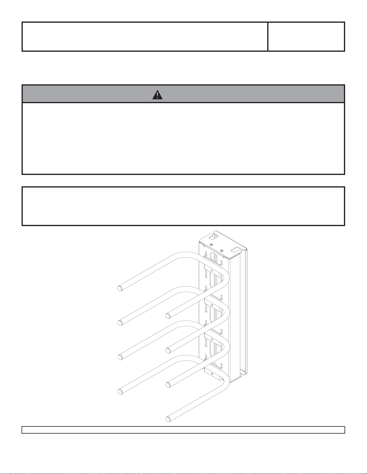
Installation and Assembly - Electronics T ower
Model: PM 610
PM 610S
PM 610W
Maximum Load Capacity (Each Shelf):
15.00 lb (7.0 kg)
Read instruction sheet before you start installation and assembly.
WARNING
• When installing Peerless wall mounts on cinder block, verify that you have a minimum of 1-3/8" of actual concrete
surface in the hole to be used for the concrete anchors. Do not drill into mortar joints! Be sure to mount in a solid
part of the block, generally 1" minimum from the side of the block. Cinder block must meet ASTM C-90 specifications. It is suggested that a standard electric drill on slow setting is used to drill the hole instead of a hammer drill to
avoid breaking out the back of the hole when entering a void or cavity .
• Concrete must be 2000 psi density minimum. Lighter density concrete may not hold concrete anchor .
• Make sure that the wall will safely support four times the combined load of the equipment and all attached hardware
and components.
IMPORTANT! Turn to the appropriate page for your wall installation.
Installations:
To Wood Stud Walls ........................................................................................................ page 2
T o Solid Concrete, Cinder Block, and Brick Walls ........................................................ page 3
1 of 10
Visit the Peerless Web Site at www.peerlessindustries.com For customer service call 1-800-729-0307 or 708-865-8870.
PUBLICATION: 12-20-99 SHEET#: 021-9003-3 03-23-05
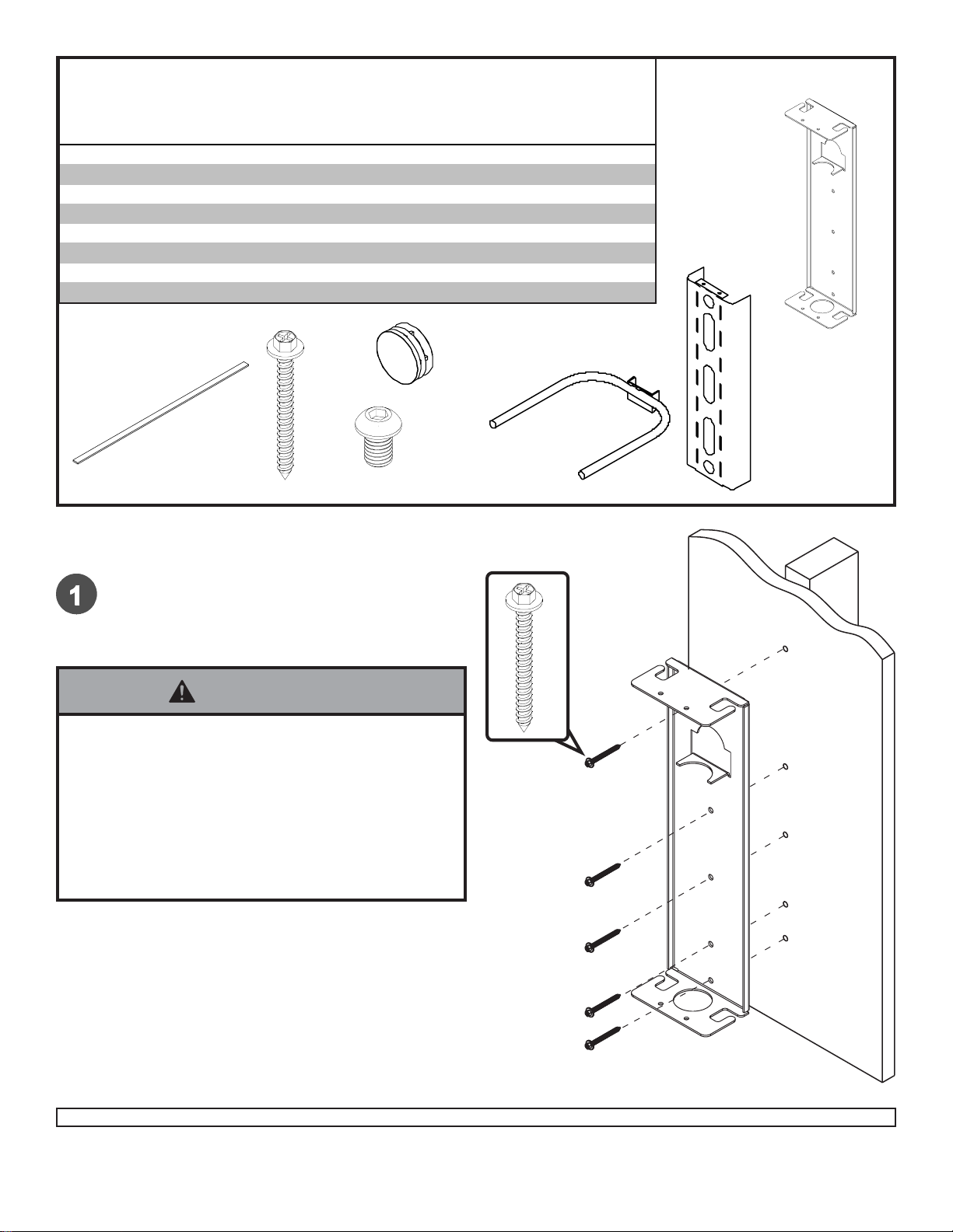
Before you start make sure all parts listed are included with your product.
Parts List
De scrip tion Qty Part # Part # Part #
wall brack et 1 021-1035 021-4035 021-2035
A
shelf bracket 1 021-1027 021-4027 021-2027
B
equipment support 4 021-1031 021-4031 021-2031
C
#14 x 2. 5" wood screw 5 5S1-015-C03 5S1-015-C03 5S1-015-C04
D
1/4-20 x 3/ 8" soc ket head s crew 4 520-2015 520-2015 520-2028
E
VCR foam 8 599-3802 599-3802 599-3802
F
endcap 8 590-1077 590-1077 590- 2 072
G
5/32" all en wrench (not shown) 1 560-9706 560-9706 560-9706
H
PM 610 PM 610S PM 610W
G
F
D
E
Installation to Wood Stud Walls
A
C
B
Drill five 5/32" (4 mm) dia. holes to a minimum
depth of 2.5" (64 mm) into stud center. Attach
wall bracket (A) using #14 x 2.5" (6 mm x 65
mm) wood screws (D).
WARNING
• Tighten wood screws so that wall plate is firmly
attached, but do not overtighten. Overtightening can
damage the screws, greatly reducing their holding
power.
• Never tighten in excess of 80 in • lb (9 N.M.).
• Make sure that mounting screws are anchored into the
center of the studs. The use of an "edge to edge" stud
finder is highly recommended.
D
A
2 of 10
Visit the Peerless Web Site at www.peerlessindustries.com For customer service call 1-800-729-0307 or 708-865-8870.
PUBLICATION: 12-20-99 SHEET#: 021-9003-3 03-23-05
WARNING
• When installing Peerless wall mounts on cinder block, verify that you have a minimum of 1-3/8" of actual concrete
surface in the hole to be used for the concrete anchors. Do not drill into mortar joints! Be sure to mount in a solid part
of the block, generally 1" minimum from the side of the block. Cinder block must meet ASTM C-90 specifications. It
is suggested that a standard electric drill on slow setting is used to drill the hole instead of a hammer drill to avoid
breaking out the back of the hole when entering a void or cavity .
• Concrete must be 2000 psi density minimum. Lighter density concrete may not hold concrete anchor .
• Make sure that the wall will safely support four times the combined load of the equipment and all attached hardware
and components.
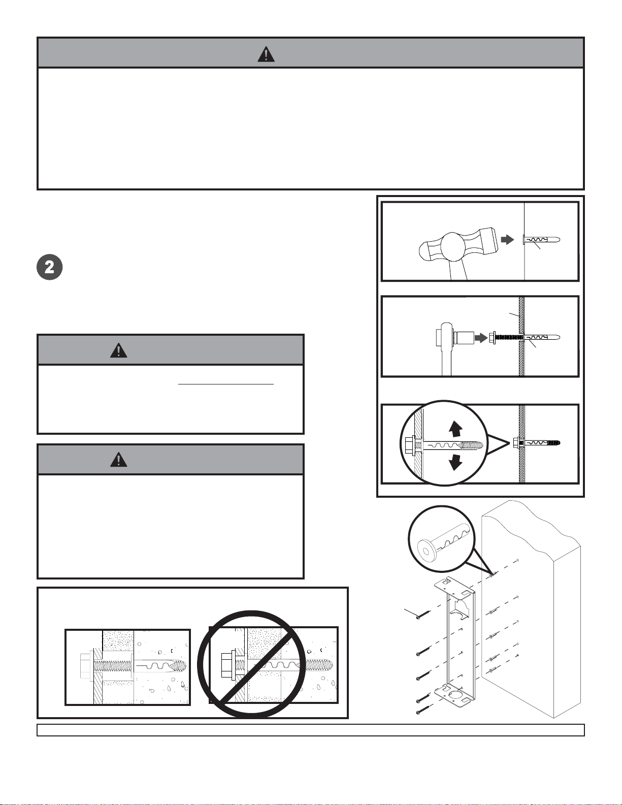
Installation to Solid Concrete,
Cinder Block, and Brick Walls
T wo sets of Alligator® concrete anchors (ACC 203) are required.
Use wall bracket (A), making sure that it is level, as a template to mark holes. Drill 1/4" (6 mm) dia. holes to a minimum
depth of 2.5" (64 mm). Insert anchors in holes flush with wall
as shown (right). Place wall bracket (A) over anchors and
secure with #14 x 2.5" (6 mm x 65 mm) wood screws. Tighten
all fasteners.
WARNING
• Tighten wood screws firmly , but do not overtighten.
Overtightening can damage the screws, greatly
reducing their holding power.
• Never tighten in excess of 80 in • lb (9 N.M.).
WARNING
• Concrete anchors are not intended for attachment to
concrete wall covered with a layer of plaster, drywall,
or other finishing material. If mounting to concrete wall
covered with plaster/drywall is unavoidable, plaster/
drywall (up to 5/8" thick) must be counterbored as
shown below. If plaster/drywall is thicker than 5/8",
custom fasteners must be supplied by installer .
1
Drill hole(s) and insert anchor(s)
2
Place bracket (A) over anchor(s) and secure with
screw(s)
A
concrete
wall
ACC 203
ACC 203
3
Tighten all fasteners
concrete
anchor
wall
bracket
CORRECT
concrete
bracket
wall
INCORRECT
D
concrete
A
CUT AW A Y VIEW
Visit the Peerless Web Site at www.peerlessindustries.com For customer service call 1-800-729-0307 or 708-865-8870.
plaster/
dry wall
plaster/
dry wall
3 of 10
PUBLICATION: 12-20-99 SHEET#: 021-9003-3 03-23-05

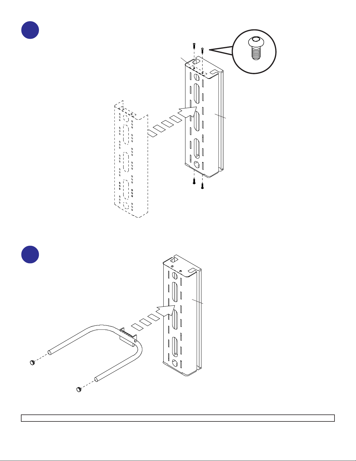
Attach shelf bracket (B) to wall
bracket (A) with four screws (E)
3
using allen wrench.
A
E
B
Snap eight end caps (G) into four equip-
4
ment supports (C). Attach four equipment
supports (C) to shelf bracket (B).
Additional equipment supports can be
ordered under model ACC102.
B
C
G
G
4 of 10
Visit the Peerless Web Site at www.peerlessindustries.com For customer service call 1-800-729-0307 or 708-865-8870.
PUBLICATION: 12-20-99 SHEET#: 021-9003-3 03-23-05

Attach eight strips of adhesive foam
5
(F) to tops of equipment supports (C).
C
F
C
5 of 10
Visit the Peerless Web Site at www.peerlessindustries.com For customer service call 1-800-729-0307 or 708-865-8870.
© 2004 Peerless Industries, Inc. All rights reserved.
Peerless is a registered trademark of Peerless Industries, Inc.
All other brand and product names are trademarks or registered trademarks of their respective owners.
PUBLICATION: 12-20-99 SHEET#: 021-9003-3 03-23-05

Instalación y ensambInstalación y ensamb
Instalación y ensamb
Instalación y ensambInstalación y ensamb
NOTA: Lea toda la hoja de instrucciones antes de iniciar la instalación y el montaje.
laje - laje -
laje -
laje - laje -
TT
T
TT
oror
or
oror
rr
e pare par
r
e par
rr
e pare par
a equipos electrónicosa equipos electrónicos
a equipos electrónicos
a equipos electrónicosa equipos electrónicos
Modelo: PM 610
PM 610S
PM 610W
ADVERTENCIA
• El concreto tiene que tener una densidad mínima de 2,000 psi. Es posible que un concreto de menos densidad no
sostenga el anclaje para concreto.
• Asegúrese de que la superficie de apoyo sostendrá, con seguridad, la carga combinada del equipo y todos los
fijadores y componentes.
Instalacións:Instalacións:
Instalacións:
Instalacións:Instalacións:
Con montantes de madera ............................................................................................................. 2
Concreto macizo, de bloques de hormigón de escorias y de ladrillo........................................ ............ 3
Visite el sitio Web de Peerless en www.peerlessmounts.com
Capacidad máxima de
soportar carga según UL:
15 lb (6.8 kg)
6 of 10
Para el Servicio al cliente llame al 1-800-729-0307 ó 708-865-8870
PUBLICADO: 12-20-99 HOJA #: 021-9003-3 03-23-05

Antes de comenzar, coteje la lista de piezas para asegurarse de que se han incluido todas las piezas.
Parts List
Descripción Cantidad
soporte de pared
A
soporte para repisas
B
soporte para el equipo
C
#14 x 2.5" tonillo
D
1/4-20 x 3/8" tonillo
E
espuma para vídeograbadoras
F
cubiertas para extremos
G
5/32" llave allen
H
PM 610 PM 610S PM 610W
o
N.
de pieza N.o de pieza N.o de pieza
021-1035 021-4035 021-2035
1
021-1027 021-4027 021-2027
1
021-1031 021-4031 021-2031
4
5S1-015-C03 5S1-015-C03 5S1-015-C04
5
520-2015 520-2015 520-2028
4
599-3802 599-3802 599-3802
8
590-1077 590-1077 590-2072
8
560-9706 560-9706 560-9706
1
G
F
Instalación en paredes conInstalación en paredes con
Instalación en paredes con
Instalación en paredes conInstalación en paredes con
D
E
A
C
B
montantes de maderamontantes de madera
montantes de madera
montantes de maderamontantes de madera
T aladre cinco agujeros de 5/32" (4 mm) de
diámetro a una profundidad mínima de 2.5" (64
mm) en el centro del montante. Fije el
soporte de pared (A) utilizando tornillos para
madera de 14 x 2.5" (6 mm x 65 mm) (D).
ADVERTENCIA
• Apriete los tornillos para madera de manera que la
unidad del soporte para proyectores se fije firmemente,
pero no en exceso. Apret arlos en exceso puede dañar
los tornillos y puede disminuir significativamente su
fuerza de sujeción.
• Nunca apriete a más de 80 pulg-lb (9 N•m).
• Asegúrese de que los tornillos de montaje estén
anclados en el centro del montante. Se recomienda
utilizar un localizador de montantes de “borde a borde”.
D
A
Visite el sitio Web de Peerless en www.peerlessmounts.com
7 of 10
PUBLICADO: 12-20-99 HOJA #: 021-9003-3 03-23-05
Para el Servicio al cliente llame al 1-800-729-0307 ó 708-865-8870

ADVERTENCIA
• El concreto tiene que tener una densidad mínima de 2,000 psi. Es posible que un concreto de menos densidad no
sostenga el anclaje para concreto.
• Asegúrese de que la superficie de apoyo sostendrá, con seguridad, la carga combinada del equipo y todos los
fijadores y componentes.
Instalación en paredes de concretoInstalación en paredes de concreto
Instalación en paredes de concreto
Instalación en paredes de concretoInstalación en paredes de concreto
macizmaciz
maciz
macizmaciz
escorias y de ladrilloescorias y de ladrillo
escorias y de ladrillo
escorias y de ladrilloescorias y de ladrillo
Se necesitan dos juegos de anclajes para concreto alligator® (ACC 203).
oo
,,
de b de b
o
,
de b
oo
,,
de b de b
Utilice el soporte de pared (A), asegurándose de que esté nivelado,
como plantilla para marcar los agujeros. T aladre agujeros de 1/4"
(6 mm) de diámetro a una profundidad mínima de 2.5" (64 mm).
Inserte los anclajes en los agujeros a ras con la pared, como se
muestra (a la derecha). Fije el soporte de pared (A) sobre los
anclajes con tornillos para madera de 14 x 2.5" (6 mm x 65 mm)
(D). Apriete todos los sujetadores.
loques de horloques de hor
loques de hor
loques de horloques de hor
migón demigón de
migón de
migón demigón de
ADVERTENCIA
• Apriete los tornillos para madera con firmeza, pero no
en exceso. Apretarlos en exceso puede dañar los
tornillos y puede disminuir significativamente su fuerza
de fijación.
• Nunca apriete a más de 80 pulg-lb (9 N•m).
ADVERTENCIA
• Siempre fije los anclajes para concreto directamente
en la pared que sostiene la carga.
• Nunca fije los anclajes para concreto a una pared de
concreto recubierta con yeso, tabique de yeso-cartón u
otro material de acabado. Si es inevitable hacer la
instalación en una superficie de concreto recubierta con
una superficie de acabado, la superficie de acabado tiene
que ser escariada, como se muestra abajo. Asegúrese de
que los anclajes para concreto no se separen del concreto cuando apriete los tornillos. Si el grosor de la capa
de yeso o tabique de yeso-cartón tiene un grosor mayor
de 5/8", el instalador tiene que suministrar las fijaciones
especiales (no aprobado por UL).
INCORRECTO
CORRECTO
1
Taladre los agujeros e inserte los anclajes
2
Coloque la placa (A) sobre los anclajes (C) y fíjela con
los tornillos
A
TECHO DE
CONCRETO
ACC 203
ACC 203
3
Apriete todas las fijaciones.
anclajes
D
concreto
VISTA EN CORTE
Visite el sitio Web de Peerless en www.peerlessmounts.com
concreto
8 of 10
A
PUBLICADO: 12-20-99 HOJA #: 021-9003-3 03-23-05
Para el Servicio al cliente llame al 1-800-729-0307 ó 708-865-8870
Fije el soporte para repisas (B)
al soporte de pared (A) con
3
cuatro tornillos (E) usando una
llave allen.
A
E
B
Coloque ocho cubiertas para extremos (G)
4
en cuatro soportes para el equipo (C).
Coloque cuatro soportes para el equipo
(C) en el soporte para repisas (B).
Puede ordenar más soportes para el
equipo bajo el modelo ACC102.
.
C
G
G
Visite el sitio Web de Peerless en www.peerlessmounts.com
9 of 10
B
PUBLICADO: 12-20-99 HOJA #: 021-9003-3 03-23-05
Para el Servicio al cliente llame al 1-800-729-0307 ó 708-865-8870

Pegue ocho tiras de espuma adhesiva
5
(F) a la parte superior de cada
soporte para el equipo (C).
C
F
C
Visite el sitio Web de Peerless en www.peerlessmounts.com
© 2004 Peerless Industries, Inc. All rights reserved.
Peerless is a registered trademark of Peerless Industries, Inc.
All other brand and product names are trademarks or registered trademarks of their respective owners.
10 of 10
PUBLICADO: 12-20-99 HOJA #: 021-9003-3 03-23-05
Para el Servicio al cliente llame al 1-800-729-0307 ó 708-865-8870
 Loading...